EP3707002B1 - A sheet processing system and method - Google Patents
A sheet processing system and method Download PDFInfo
- Publication number
- EP3707002B1 EP3707002B1 EP18796497.8A EP18796497A EP3707002B1 EP 3707002 B1 EP3707002 B1 EP 3707002B1 EP 18796497 A EP18796497 A EP 18796497A EP 3707002 B1 EP3707002 B1 EP 3707002B1
- Authority
- EP
- European Patent Office
- Prior art keywords
- printing
- sheet
- frame
- rollers
- die
- Prior art date
- Legal status (The legal status is an assumption and is not a legal conclusion. Google has not performed a legal analysis and makes no representation as to the accuracy of the status listed.)
- Active
Links
Images


Classifications
-
- B—PERFORMING OPERATIONS; TRANSPORTING
- B41—PRINTING; LINING MACHINES; TYPEWRITERS; STAMPS
- B41F—PRINTING MACHINES OR PRESSES
- B41F13/00—Common details of rotary presses or machines
- B41F13/0024—Frames
-
- B—PERFORMING OPERATIONS; TRANSPORTING
- B41—PRINTING; LINING MACHINES; TYPEWRITERS; STAMPS
- B41F—PRINTING MACHINES OR PRESSES
- B41F13/00—Common details of rotary presses or machines
- B41F13/08—Cylinders
- B41F13/24—Cylinder-tripping devices; Cylinder-impression adjustments
- B41F13/26—Arrangement of cylinder bearings
- B41F13/30—Bearings mounted on sliding supports
-
- B—PERFORMING OPERATIONS; TRANSPORTING
- B41—PRINTING; LINING MACHINES; TYPEWRITERS; STAMPS
- B41F—PRINTING MACHINES OR PRESSES
- B41F13/00—Common details of rotary presses or machines
- B41F13/08—Cylinders
- B41F13/24—Cylinder-tripping devices; Cylinder-impression adjustments
- B41F13/34—Cylinder lifting or adjusting devices
- B41F13/36—Cams, eccentrics, wedges, or the like
-
- B—PERFORMING OPERATIONS; TRANSPORTING
- B41—PRINTING; LINING MACHINES; TYPEWRITERS; STAMPS
- B41F—PRINTING MACHINES OR PRESSES
- B41F19/00—Apparatus or machines for carrying out printing operations combined with other operations
- B41F19/008—Apparatus or machines for carrying out printing operations combined with other operations with means for stamping or cutting out
-
- B—PERFORMING OPERATIONS; TRANSPORTING
- B41—PRINTING; LINING MACHINES; TYPEWRITERS; STAMPS
- B41F—PRINTING MACHINES OR PRESSES
- B41F33/00—Indicating, counting, warning, control or safety devices
- B41F33/04—Tripping devices or stop-motions
- B41F33/08—Tripping devices or stop-motions for starting or stopping operation of cylinders
-
- B—PERFORMING OPERATIONS; TRANSPORTING
- B41—PRINTING; LINING MACHINES; TYPEWRITERS; STAMPS
- B41F—PRINTING MACHINES OR PRESSES
- B41F5/00—Rotary letterpress machines
- B41F5/02—Rotary letterpress machines for printing on sheets
-
- B—PERFORMING OPERATIONS; TRANSPORTING
- B41—PRINTING; LINING MACHINES; TYPEWRITERS; STAMPS
- B41F—PRINTING MACHINES OR PRESSES
- B41F5/00—Rotary letterpress machines
- B41F5/24—Rotary letterpress machines for flexographic printing
-
- B—PERFORMING OPERATIONS; TRANSPORTING
- B41—PRINTING; LINING MACHINES; TYPEWRITERS; STAMPS
- B41P—INDEXING SCHEME RELATING TO PRINTING, LINING MACHINES, TYPEWRITERS, AND TO STAMPS
- B41P2213/00—Arrangements for actuating or driving printing presses; Auxiliary devices or processes
- B41P2213/40—Auxiliary devices or processes associated with the drives
- B41P2213/42—Vibration-dampers for machine parts
Definitions
- the present invention relates to a sheet processing system and a corresponding method.
- the machines generally comprise a feeding unit, apt to provide sheets or strips of cardboard at a given predetermined distance, a printing unit of the flexographic type, apt to print, by means of rollers and printing blocks apt to transfer each a color onto the sheet of cardboard, a die-cutting assembly, comprising a roller, supporting a die-cutter on the surface, apt to cut, crease or define fold or cut lines.
- Said rollers and elements are all perfectly aligned and moved simultaneously and at identical speeds to allow a perfect alignment of the crease and cut lines coming from the die-cutting assembly and of the single colors coming from the printing assemblies.
- the rollers all have one same diameter so that the sheet of cardboard is perfectly carried and printed or cut in a perfectly aligned manner.
- said systems are relatively little flexible and it is impossible to vary the size of the rollers in financially advantageous times.
- rollers with smaller diameters are faster, easier to handle and require less energy to use, but they do not allow sheets of cardboard to be made processed with a greater length with respect to the length of the circumference of the rollers.
- Rollers with larger diameters are bulkier and more complex to use, but they allow sheets to be processed with greater and not smaller lengths.
- Two classical roller circumference lengths are 66 in (1676.4 mm) and 99 in (2514.6 mm).
- the printing step is carried out at a low speed.
- the technical task underlying the present invention is to create a sheet processing system, which is substantially able to overcome the stated drawbacks.
- the system 1 comprises a plurality of units, each for implementing a different process or activity.
- a die-cutting unit 10 is present, a printing unit 20 of the flexographic type, a unit for inserting the sheets 2 and a unit for the removal or subsequent processing of the sheets 2.
- the system 1 defines a processing line 1b, which is the line along which the sheet 2 is moved, preferably, the processing line is straight and defines a direction of processing.
- the processing line coincides with a printing line 1a.
- the direction along the processing line is called longitudinal hereinafter, preferably it is perpendicular to the vertical direction and to a transverse direction which completes the three orthogonal axes.
- Said processing line is preferably maintained by means of a plurality of coated toothed belts and/or of movement rollers 3.
- rollers with different diameters preferably move at identical tangential speeds and at different rotational speeds to one another and inversely proportionate to the diameters.
- the unit for inserting the sheets 2 allows the sheets 2 to be inserted into the system at intervals of time comparable with predetermined and preferably constant intervals of space. It is known in itself.
- the die-cutting unit 10 is illustrated in Figures 1a - 1c . It is apt to die-cut the sheet 2, in other words to make cuts or fold lines or cut lines along the same sheet 2.
- Each die-cutting roller 11 thus comprises a die-carrying roller 11b and the die-cutter 11a, arranged on the surface of the roller and generally consisting of wooden shells comprising metal sheets and the like, apt to implement said processing.
- the die-cutting unit 10 suitably comprises movement means 12 for the die-cutting rollers 11, apt to arrange the die-cutting rollers 11 in a working position, wherein they are apt to die-cut the sheet 2, and in a resting position, wherein they are not active and lie at a distance from the sheet 2 and it is thus possible to operate on the same, for example change the die-cutter 11a.
- the movement means 12 are further apt to move the die-cutting rollers 11 rapidly, independently of one another. Consequently, the rollers can occupy mutually different means and spaces and they can be of different sizes, in particular with different diameters.
- the term rapidly is understood to mean that the operation is carried out in very short periods of time with respect to the times in which it would be carried out if the die-cutting unit 10 comprised only one roller, constrained to the rest of the unit by means of the traditional constraint means, such as screws and bolts.
- the changing of the roller in the die-cutting unit 20 can be carried out in a few minutes or even just in a few seconds.
- the movement means 12 comprise a first movement arm 120 having ends firmly constrained to a first hinge 121a, and to a second hinge 121b.
- the first hinge 121a is placed at a distance from the die-cutting roller 11 and, in particular, at a distance from the center of the roller 11, in the plane perpendicular to the transverse direction, greater than the diameter of the roller 11.
- the second hinge 121b is preferably placed close to the die-cutting roller 11 and at a distance from the center of the roller itself and preferably close to the surface thereof.
- the movement means 12 comprise a three-hinged arch 12a with an extendible arm. It comprises said first and said second hinge 121a and 121b and said first arm 120.
- Each three-hinged arch 12a comprises a second arm 122 connected by means of a third hinge 122a, preferably fixed to the structure of the die-cutting unit 10 and positioned in a vertically upper, spaced apart position, in particular at a distance greater than the diameter of the roller 11 from the center of the die-cutting roller 11.
- the second arm 122 is also a fluid dynamic, preferably hydraulic, cylinder or an electric linear actuator, apt to move the three-hinged arch 12a and consequently the movement means 12 and the roller 11.
- Said structure enables an ideal and selectable movement by means of an appropriate choice of the position of the hinges of the rollers 11, so that the same do not interfere reciprocally.
- rollers can comprise guides apt to support the rollers, in particular during the movement thereof.
- the working position is appropriately interposed between the first hinges 121a, so it is in the middle with respect to the resting positions of the two die-cutting rollers 11.
- the die-cutting unit 10 further comprises an accompanying roller 13, which is preferably movable by means of a telescopic rod or the like.
- the accompanying roller 13 is apt to arrange itself in said working position, when the die-cutting rollers 11 are both in the resting position ( Fig. 1b ) so as to keep the processing line 1b in a resting position, with sheets 2 which are not die-cut.
- the die-cutting rollers 11 have different sizes from each other and appropriately, they have circumferences with such lengths as to have a common divider, and said circumferences can be obtained by dividing each of said lengths by a whole number smaller than 5.
- the common divider must be multiplied by two to obtain the diameter or circumference of a first die-cutting roller 11 and by three to obtain the diameter or circumference of a second die-cutting roller 11.
- the two rollers have circumferences in reciprocal proportions of 2 to 3 for reasons clarified below.
- the dimensions of the circumferences are preferably 66 in and 99 in.
- the flexographic printing unit 20 is arranged upstream of the die-cutting unit.
- the printing roller 22 thus comprises a printing block carrying roller 22b and the printing block 22a.
- the printing block 22a known in itself, is a raised surface made of rubber or photopolymeric materials apt to stamp the print directly on the sheet 2.
- the printing rollers 22 have different dimensions with respect to at least one of the die-cutting rollers 12, preferably the largest one, and appropriately, they have circumferences with such lengths as to have a common divider and said circumferences can be obtained by dividing each of said lengths by a full number smaller than 5.
- the common divider must be multiplied by two to obtain the diameter or circumference of the printing roller 22 and by three to obtain the diameter or circumference of the second die-cutting roller 11.
- the two rollers have circumferences in reciprocal proportions of 2 to 3 for reasons clarified below.
- the dimensions of the circumferences are preferably 66 in and 99 in.
- Each printing assembly 21 further comprises a counter-pressure roller 210 opposite the printing roller 22, apt to carry the sheet 2 and press the printing roller 22.
- the printing assembly then comprises inking means 211 for the printing roller 22.
- Said inking means 211 preferably comprise a roller, called by convention anilox roller 212 or Anilox, made of steel or ceramic and in contact with the printing roller 22.
- the anilox roller 212 further draws the ink from or with an inking roller 213, also acting as a blade, preferably made of rubber.
- the two rollers are in contact and define a containment zone 214 for the ink between the rollers 212 and 213.
- a blade system is included, performing the same function and known in itself.
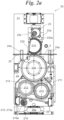
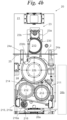
- the inking means 211 also comprise limitation means 215 for the ink placed on the printing roller 21. Such limitation can also occur by limiting the ink on the anilox roller 212 or on the inking roller 213. They comprise either distancing means 215a for rollers part of the inking means 211, in particular for the anilox roller 212 from the printing roller 22 ( Fig. 2b ) or from the inking roller.
- the distancing means 215a comprise an eccentric 216 with a fixed axis 216a with respect to the printing roller 22, moving a shoulder supporting the anilox 212 and inking 213 rollers.
- the eccentrics 216 are preferably moved by brushless electric motors.
- each printing assembly 21 further comprises automatic, programmable displacement means 23 for said printing rollers 22, apt to distance at least one of the printing rollers 22 from the printing line 1a during the printing process, so that the printing roller 22 does not print the sheet 2.
- the term automatic is understood to mean that the operation is not carried out manually, but by means of special devices, and the term programmable is understood to mean that the printing moment can be selected from the control means of the printing unit 20.
- the displacement means 23 are apt to move each single said printing roller 22 individually and independently of the others.
- the displacement means 23 move a plurality of rollers simultaneously, in particular the printing roller 22, the anilox roller 212 and the inking roller 213. They can operate with any kind of means, for example, endless screws, fluid dynamic cylinders and others.
- they operate with two eccentrics 23a, which are opposite and aligned in a transverse direction with the rotation axis 23b parallel to the transverse direction.
- the eccentrics 23a are thus movably constrained to a frame 24.
- the frame 24 is thus apt to be moved by the displacement means 23.
- the frame 24 is apt to be moved at least downwards and at least upwards by means of the eccentrics 23a at least with respect to the vertical direction.
- the frame 24 is preferably a movable frame with respect to a fixed structure included in each printing assembly 21, bearing at least the printing roller 22.
- the frame 24 also supports other rollers 212 and 213.
- the frame 24 is preferably movably constrained to at least one guide 24a.
- the frame 24 is movably constrained to two guides 24a.
- eccentrics 23a have a rotation axis constrained to the structure fixed to the floor of the printing assembly 21 and they are preferably moved by brushless electric motors.
- eccentrics 23a are movably constrained to the frame 24 by means of at least one bar 230.
- Said bar 230 is preferably a rigid bar and defines two connection points with the eccentric 23a and the frame 24 respectively.
- the fourth hinge 230a preferably consists of an unstable constraint between the eccentric 23a and the bar 230.
- the fifth hinge 230b preferably consists of an unstable constraint between the bar 230 and the frame 24.
- each eccentric 23a is movably constrained to the frame 24 by means of two bars 230.
- the eccentrics 23a comprising the bars 230 apt to transmit the movement of the eccentrics 23a aligned with the frame 24 (in detail, preferably by means of the fourth and fifth hinge 230a, 230b), the frame 24 and the guides 24a preferably define a crank-handle mechanism.
- Each printing assembly 21 comprises damping means 26.
- the damping means 26 are preferably elastically deformable means adapted to deform upon compression.
- the damping means 26 are arranged between the frame 24 and a fixed point so as to damp the movement of the frame 24.
- the fixed point can thus be a portion of the fixed structure or, for example, the floor or any other fixed point, such as other external structures.
- the damping means 26 are arranged between the frame 24 and the floor, along said vertical direction, so as to damp the movement of the frame 24 along the vertical direction.
- the damping means 26 comprise a pneumatic cylinder 26a.
- the pneumatic cylinder 26a is known in itself and of the elastic type, for example, with simple effect, commonly known as Air Spring or Air Bellow. Similar cylinders are marketed by the company Generalmatic s.r.l. and described on web page: http://www.generalmatic.com/ECM31.php.
- the damping means 26 could comprise other components, such as electromechanical or hydraulic dampers or, again, elastomeric elements apt to absorb the loads of the frame 24, deforming and giving rise to hysteresis cycles repeated depending on the movements imposed by the eccentrics 23a.
- the damping means 26 preferably consist of dampers for the previous crank-handle mechanism.
- the damping means 26 are apt to damp and absorb the loads caused by the descending movement of the frame 24 and facilitate and push the movement of the frame 24 upwards along the vertical direction.
- the damping means 26 make a passive actuator when they push the movement of the frame.
- the pneumatic cylinder 26a when the pneumatic cylinder 26a is allowed to return to the non-deformed configuration, it exerts a force in a vertical direction, apt to lift the frame 24.
- damping means 26 also include at least one storage tank 26b.
- the storage tank 26b could be comprised inside the unit or external. Preferably, it is external so that its volume does not affect the dimensions of the unit.
- the storage tank 26b is in fluid passage communication with the pneumatic cylinder 26a.
- they are connected in such a way that, when the pneumatic cylinder 26a is deformed, the variation in overall volume of the damping means 26 including the pneumatic fluid is less than 20%.
- the variation in overall volume is preferably less than 10%. Even more appropriately, the variation in overall volume is less than 5%.
- this latter aspect allows the operating pressure of the damping means 26 to be kept substantially constant during the whole activity and, in particular, during the damping and suspension steps.
- connection between the storage tank 26b and the pneumatic cylinder 26a is preferably always open during the operational steps.
- the displacement means 23 can also be coupled to support means 25, such as rollers or rods for the sheet in the absence of the printing roller ( Fig. 2b ).
- the successive processing or extraction unit for the processed sheets 2 is of a known type.
- the invention comprises a new processing procedure for the sheet 2 and, in particular, a new printing procedure.
- Such procedure is preferably carried out by means of the described processing system 1 for the sheet 2 and, in particular, by means of the described printing unit 20.
- a sheet is inserted having a length, in the direction of the printing line 1a, which is greater than the circumference of two printing rollers 22, and preferably smaller or equal to the size of the circumference of the die-cutting roller 11 with larger diameter.
- at least one of the printing rollers 22 prints only one part of the sheet 2 and is distanced from the printing line 1a, so as not to print the whole sheet 2 and so as not to repeat the print of the motif of the printing block thereof on the sheet 2.
- several printing rollers 22, preferably two, are synchronized with respect to the position on the sheet 2, so that a plurality of printing rollers 22 print different and complementary portions of the sheet 2 for a printed surface length, in the direction of the printing line 1a, which is greater than the circumference of the printing rollers 22 and preferably equal to the length of the sheet 2, so that the printing rollers 22 can print up to the whole length of the sheet 2, preferably with the same ink color.
- the printing rollers 22 are divided internally into groups, synchronized with respect to the position on the sheet 2, so that each assembly of printing rollers prints a single color.
- the printing rollers 22 are divided internally into groups, synchronized with respect to the position on the sheet 2, so that each assembly of printing rollers prints a single color.
- four printing rollers 22 are shown, synchronized two by two and apt to print two colors overall. Synchronization preferably takes place on adjoining printing rollers 22, but it can also take place in an alternate manner, in other words, the first synchronized with the third and the second with the fourth.
- the term "synchronized with respect to the position on the sheet 2" or simply “synchronized” does not mean the classical synchronization of the rollers, which each traditional printing machine needs, for example, when each roller prints a single color, but the particular synchronization described and illustrated.
- said processing procedure for the sheet 2 also comprises the die-cutting of the sheet 2, preferably by means of the described die-cutting unit 10 having and using a die-cutting roller 11 with a circumference whose length is greater, equal or smaller than the length of the sheet 2 and also consequently, greater than the length of the circumferences of the printing rollers 22 and having, with the same, the described proportion between the circumference lengths, in other words, having a common divider, which can be obtained by dividing each of said lengths by a full number smaller than 5, as described previously.
- the length of the sheet 2 is also preferably smaller than the double of the circumference of the printing rollers 22. Consequently, the die-cutting roller 11 is apt to die-cut, if necessary, the whole sheet 2, while the printing rollers 22 are apt to print up to the whole sheet 2 because they are synchronized with respect to the position on the sheet 2, as described previously.
- the die-cutting roller 11 and the printing rollers 22 are preferably initially synchronized in the same printing position, so that the circumferential imbalance between the rollers is equal to, or a module of, the distance between rollers and so that the printing positions are aligned. They also revert to being synchronized in such position after a number of turns equal to the highest of the full numbers which are obtained by dividing the circumferences of the rollers 11 and 22 by said common divider.
- the sheets are inserted by the sheet 2 insertion unit, preferably at constant intervals of time, which, the advancing speed along the processing line 1b being constant, correspond to constant and predetermined distances. Said distances are preferably equal to the diameter of the printing rollers 22, more preferably equal to 66 in.
- rollers 22 and 11 are aligned in one same angular position and have identical distances to the circumference thereof.
- an arrow placed at the top indicates the advancing direction and course of the cardboard during the processing.
- the system without die-cutting and in one only color, the system must print the first half of a sheet 2 having a length greater than the distance between the printing rollers 22 and the circumference thereof.
- the roller is 66 in and the sheet 99 in.
- roller 22 In such case, only one roller 22 is sufficient, thus other rollers 22 are distanced from the printing line 1a by the displacement means 23.
- Said roller 22 used has a printing block 22a with a length of 49.5 in, thus equal to 3/4 of the circumference of the printing roller 22.
- the sheet 22 is thus inserted so that the first edge of the sheet 2 in a longitudinal direction, reaches the start of the printing block 22a.
- the printing block On rotating, the printing block is thus printed on the sheet 2 and, when it reaches the end, the displacement means 23 distance the roller 22 from the printing line, so that the same is not printed again on the end portion of the sheet 2.
- the system In a second example, without die-cutting and in two colors, the system must print the whole sheet 2 having a length greater than the circumference of the printing rollers 22, in this example equal to the reciprocal distance thereof For example, the roller is 66 in and the sheet 99 in.
- Each color is divided into two consecutive printing rollers 22, each bearing half of the total portion to be printed, and therefore a printing block of 49.5 in, thus equal to 3/4 of the circumference of the printing roller 22.
- all of the rollers are synchronized ( Fig. 3a ) with the position 0°, represented by a vertical line on the figures, facing upwards and the printing blocks 22a of the first and third roller 22, which cover the angular positions from 0 to 3/4 of a round angle, and the printing blocks 22a of the second and fourth roller 22, which cover the angular positions from 1/2 to 1/4 of a round angle, or rather the whole of the circumference, except for the angular segment between 1/4 of a round angle and 1/2 of the round angle.
- the sheet 2 is thus inserted so that the first edge of the sheet 2, in a longitudinal direction, reaches the start of the printing block 22a ( Fig. 3a ).
- the printing block 22a of the first roller 22 thus prints on the sheet 2 and, when it reaches the end, the displacement means 23 distance the roller 22 from the printing line, so that the same does not print on the end portion of the sheet 2 again.
- the sheet 2 consequently reaches the printing block 22a of the second roller 22 ( Fig. 3b ) and the beginning of the sheet 2 is always aligned with the 0° position of the second roller 22, since the rollers and the sheet rotate and advance at the same tangential and linear speed and cover the same distance.
- the sheet 2 reaches the printing block 22a of the second roller 22, the latter is distanced from the printing line 1a by the movement means 23. In fact, the first half of the sheet 2 is already printed by the first roller 22a.
- the sheet 2 advances and the roller 22 rotates and when the latter covers 3/4 of the circumference ( Fig. 3c ), which correspond to 49.5 in, the sheet 2 covers the same 49.5 in, which correspond to half the length thereof.
- the sheet 2 thus faces the non-printed half thereof, the second half, at the beginning of the printing block 22a, in other words in the angular position equal to 1/2 of a round angle.
- the rollers 22 terminate a fourth of a turn, which separates them from the end of the second turn ( Fig. 3d ) and the sheet 2 reaches the beginning of the third roller 22, for which the 0° position is aligned at the beginning of the sheet 2.
- the third roller starts to print the second color starting from the beginning of the sheet 2, while the second roller is finishing the print of the first color.
- the second sheet 2 can be inserted.
- the printing of the second color proceeds in the same way as the printing of the first color.
- the system must print in two colors and die-cut the whole sheet 2 with a length greater than the circumference of the printing rollers 22.
- the roller is 66 in and the sheet 99 in.
- the die-cutting roller 11 with a selected diameter is initially placed in a working position.
- Each color is divided into two consecutive printing rollers 22, each bearing half of the total portion to be printed, and thus a 49.5 in printing block, therefore equal to 3/4 of the circumference of the printing roller 22.
- This example is identical to the one previously presented, with the only difference that, after the printing of the second color ( Fig. 3e and 3f ) the sheet 2 reaches the beginning of the die-cutting roller 11 and is die-cut thereby along the whole length.
- the first edge of the sheet 2 in a longitudinal direction reaches the beginning of the die-cutter 11a ( Fig. 3f ).
- the die-cutter 11a of the roller 11 die-cuts the sheet 2 in a substantially traditional manner.
- the processing system 1 achieves important advantages.
- the system 1 is extremely flexible and allows sheets with a length greater than the length of the circumference of the printing rollers, or also sheets with a reduced length to be processed, in particular, printed and die-cut.
- the same system can process 66 in and 99 in sheets.
- the processing system 1, and, in particular each printing assembly 21, comprises a movement mechanism, which significantly reduces wear and volume and increases the control of the printing roller 22.
- the loads caused by the frame 24 and by the movement thereof are damped by the damping means 26, which act both as a damper and as accompanying means in the step of lifting the frame 24 by the movement means 23 according to the mechanisms described in the document.
- the fact of using external storage tanks 26b can allow extremely efficient damping means 26 to be made, wherein, for example, the maximum fluctuation pressure is around 0.5 bars.
Landscapes
- Engineering & Computer Science (AREA)
- Mechanical Engineering (AREA)
- Rotary Presses (AREA)
- Printing Methods (AREA)
- Details Of Cutting Devices (AREA)
Applications Claiming Priority (2)
| Application Number | Priority Date | Filing Date | Title |
|---|---|---|---|
| IT201700127604 | 2017-11-09 | ||
| PCT/IB2018/057921 WO2019092520A1 (en) | 2017-11-09 | 2018-10-12 | A sheet processing system and method |
Publications (2)
| Publication Number | Publication Date |
|---|---|
| EP3707002A1 EP3707002A1 (en) | 2020-09-16 |
| EP3707002B1 true EP3707002B1 (en) | 2025-02-12 |
Family
ID=61527161
Family Applications (1)
| Application Number | Title | Priority Date | Filing Date |
|---|---|---|---|
| EP18796497.8A Active EP3707002B1 (en) | 2017-11-09 | 2018-10-12 | A sheet processing system and method |
Country Status (10)
| Country | Link |
|---|---|
| US (1) | US11345138B2 (pl) |
| EP (1) | EP3707002B1 (pl) |
| JP (1) | JP7349736B2 (pl) |
| CN (1) | CN111315582B (pl) |
| AU (1) | AU2018364530B2 (pl) |
| CA (1) | CA3079063A1 (pl) |
| ES (1) | ES3024333T3 (pl) |
| PL (1) | PL3707002T3 (pl) |
| PT (1) | PT3707002T (pl) |
| WO (1) | WO2019092520A1 (pl) |
Families Citing this family (2)
| Publication number | Priority date | Publication date | Assignee | Title |
|---|---|---|---|---|
| WO2022106427A1 (en) | 2020-11-19 | 2022-05-27 | Bobst Lyon | Converting machine with height adjustment |
| IT202300010797A1 (it) * | 2023-05-29 | 2024-11-29 | Koenig & Bauer Celmacch S R L | Macchina di stampa flessografica |
Family Cites Families (17)
| Publication number | Priority date | Publication date | Assignee | Title |
|---|---|---|---|---|
| JPS61179742A (ja) * | 1984-12-27 | 1986-08-12 | Koichiro Matsuo | シ−ト印刷機 |
| JPH04272852A (ja) * | 1991-02-28 | 1992-09-29 | Kanzaki Paper Mfg Co Ltd | オンマシン印刷装置 |
| JPH07266535A (ja) * | 1994-03-28 | 1995-10-17 | Toppan Printing Co Ltd | グラビア印刷装置 |
| DE19816659B4 (de) * | 1997-05-26 | 2005-04-07 | Heidelberger Druckmaschinen Ag | Verfahren und Vorrichtung zum Schutz gegen das Eindringen von Fremdkörpern in einen Walzenspalt |
| JP3370600B2 (ja) | 1998-04-17 | 2003-01-27 | 株式会社イソワ | フレキソ印刷機 |
| US6612233B2 (en) * | 2000-02-18 | 2003-09-02 | Mitsubishi Heavy Industries, Ltd. | Sheet feed offset press |
| CN102152610B (zh) * | 2010-12-15 | 2013-08-14 | 东莞市中崎机械有限公司 | 一种具有覆膜装置的间歇式标签印刷机 |
| KR20130003560A (ko) * | 2011-06-30 | 2013-01-09 | 주식회사 에스에프에이 | 인쇄장치 |
| DE102011119088A1 (de) * | 2011-11-22 | 2013-05-23 | Gallus Druckmaschinen Gmbh | Flexodruckwerk mit Kniehebelsystem |
| CN103660532B (zh) * | 2012-09-04 | 2017-08-22 | 海德堡印刷机械股份公司 | 用于再调节印刷机中的辊的压力的方法和装置 |
| JP6156981B2 (ja) * | 2013-05-02 | 2017-07-05 | 株式会社Isowa | 段ボールシート製函機 |
| US9840074B2 (en) * | 2014-04-29 | 2017-12-12 | Bobst Firenze S.R.L. | Method and device for replacing the printing roller of a printing unit of a printing machine |
| CN204472085U (zh) * | 2015-02-04 | 2015-07-15 | 新昌县远润纺织机械有限公司 | 一种圆网印花机的横向导带整位装置 |
| ITUB20150070A1 (it) | 2015-03-10 | 2016-09-10 | Engico Srl | Impianto per la lavorazione di fogli |
| ITUB20150564A1 (it) | 2015-03-10 | 2016-09-10 | Engico Srl | Impianto per la lavorazione di fogli |
| CN105946339B (zh) * | 2016-06-22 | 2018-02-13 | 浙江东山广信数码印花设备有限公司 | 适用于高弹性面料的移动式贴布装置 |
| CN107297947B (zh) * | 2017-06-26 | 2022-08-09 | 浙江炜冈科技股份有限公司 | 新型间歇式胶印机 |
-
2018
- 2018-10-12 CA CA3079063A patent/CA3079063A1/en active Pending
- 2018-10-12 AU AU2018364530A patent/AU2018364530B2/en active Active
- 2018-10-12 CN CN201880072706.5A patent/CN111315582B/zh active Active
- 2018-10-12 US US16/757,556 patent/US11345138B2/en active Active
- 2018-10-12 PT PT187964978T patent/PT3707002T/pt unknown
- 2018-10-12 EP EP18796497.8A patent/EP3707002B1/en active Active
- 2018-10-12 PL PL18796497.8T patent/PL3707002T3/pl unknown
- 2018-10-12 WO PCT/IB2018/057921 patent/WO2019092520A1/en not_active Ceased
- 2018-10-12 JP JP2020526202A patent/JP7349736B2/ja active Active
- 2018-10-12 ES ES18796497T patent/ES3024333T3/es active Active
Also Published As
| Publication number | Publication date |
|---|---|
| PT3707002T (pt) | 2025-03-13 |
| JP7349736B2 (ja) | 2023-09-25 |
| JP2021502276A (ja) | 2021-01-28 |
| US11345138B2 (en) | 2022-05-31 |
| CA3079063A1 (en) | 2019-05-16 |
| RU2020113723A3 (pl) | 2022-04-08 |
| AU2018364530B2 (en) | 2024-04-04 |
| ES3024333T3 (en) | 2025-06-04 |
| WO2019092520A1 (en) | 2019-05-16 |
| BR112020009031A2 (pt) | 2020-10-06 |
| EP3707002A1 (en) | 2020-09-16 |
| AU2018364530A1 (en) | 2020-05-07 |
| CN111315582A (zh) | 2020-06-19 |
| CN111315582B (zh) | 2022-04-12 |
| RU2020113723A (ru) | 2021-10-18 |
| PL3707002T3 (pl) | 2025-04-28 |
| US20210197544A1 (en) | 2021-07-01 |
Similar Documents
| Publication | Publication Date | Title |
|---|---|---|
| EP3707002B1 (en) | A sheet processing system and method | |
| US9522477B2 (en) | Corrugated paperboard box making machine | |
| US20030036468A1 (en) | Device and method for automatic processing of sheet-shaped print materials with interchangeable functions | |
| WO2016080072A1 (ja) | シート供給装置 | |
| US11052562B2 (en) | Tool-holder column, unit for converting a flat substrate, and methods for removing a rotary tool from and mounting it in a conversion unit | |
| GB2302312A (en) | Direct drive for printing machines | |
| EP1767358A2 (de) | Druckeinheit einer Rollenrotationsdruckmaschine | |
| ITMI20011737A1 (it) | Gruppo di stampa, particolarmente per macchina da stampa flessografica | |
| US2482613A (en) | Manufacture of unit strip assemblies | |
| JPH01252429A (ja) | 処理機械へのシートの複式供給装置 | |
| RU2782180C2 (ru) | Система обработки листов | |
| BR112020009031B1 (pt) | Unidade de impressão flexográfica, sistema para o processamento de folha de papel, método de impressão e método de processamento | |
| EP2343186A1 (en) | Variable cutoff oscillating web printing press, and method | |
| CN206999863U (zh) | 提高广告印刷质量的装置 | |
| CN113135030B (zh) | 一种基于二次动作的渐进式压印方法 | |
| CN102336031B (zh) | 一种手提袋机的袋底夹调节装置 | |
| JP6683705B2 (ja) | 軸受、平坦基材変換ユニット、回転工具の取付け及び取外しのための方法 | |
| CN107235362A (zh) | 专用于印刷品印刷过程的支撑结构 | |
| CN104891145A (zh) | 一种输送线有序送料机构 | |
| DE10259495A1 (de) | Übertragungsvorrichtung für Druckfarbe | |
| EP1836045A1 (en) | Embossing device with embossing roller composed of an interchangeable sleeve and supporting centers | |
| ITUB20150070A1 (it) | Impianto per la lavorazione di fogli | |
| CN113119642B (zh) | 一种压印工作站 | |
| CN210502055U (zh) | 一种便于更换压纹轴的深压纹机 | |
| CN107323086B (zh) | 宣传单生产用限位装置 |
Legal Events
| Date | Code | Title | Description |
|---|---|---|---|
| STAA | Information on the status of an ep patent application or granted ep patent |
Free format text: STATUS: UNKNOWN |
|
| STAA | Information on the status of an ep patent application or granted ep patent |
Free format text: STATUS: THE INTERNATIONAL PUBLICATION HAS BEEN MADE |
|
| PUAI | Public reference made under article 153(3) epc to a published international application that has entered the european phase |
Free format text: ORIGINAL CODE: 0009012 |
|
| STAA | Information on the status of an ep patent application or granted ep patent |
Free format text: STATUS: REQUEST FOR EXAMINATION WAS MADE |
|
| 17P | Request for examination filed |
Effective date: 20200417 |
|
| AK | Designated contracting states |
Kind code of ref document: A1 Designated state(s): AL AT BE BG CH CY CZ DE DK EE ES FI FR GB GR HR HU IE IS IT LI LT LU LV MC MK MT NL NO PL PT RO RS SE SI SK SM TR |
|
| AX | Request for extension of the european patent |
Extension state: BA ME |
|
| DAV | Request for validation of the european patent (deleted) | ||
| DAX | Request for extension of the european patent (deleted) | ||
| STAA | Information on the status of an ep patent application or granted ep patent |
Free format text: STATUS: EXAMINATION IS IN PROGRESS |
|
| 17Q | First examination report despatched |
Effective date: 20230330 |
|
| GRAP | Despatch of communication of intention to grant a patent |
Free format text: ORIGINAL CODE: EPIDOSNIGR1 |
|
| STAA | Information on the status of an ep patent application or granted ep patent |
Free format text: STATUS: GRANT OF PATENT IS INTENDED |
|
| INTG | Intention to grant announced |
Effective date: 20240925 |
|
| GRAS | Grant fee paid |
Free format text: ORIGINAL CODE: EPIDOSNIGR3 |
|
| GRAA | (expected) grant |
Free format text: ORIGINAL CODE: 0009210 |
|
| STAA | Information on the status of an ep patent application or granted ep patent |
Free format text: STATUS: THE PATENT HAS BEEN GRANTED |
|
| AK | Designated contracting states |
Kind code of ref document: B1 Designated state(s): AL AT BE BG CH CY CZ DE DK EE ES FI FR GB GR HR HU IE IS IT LI LT LU LV MC MK MT NL NO PL PT RO RS SE SI SK SM TR |
|
| REG | Reference to a national code |
Ref country code: GB Ref legal event code: FG4D |
|
| REG | Reference to a national code |
Ref country code: CH Ref legal event code: EP |
|
| REG | Reference to a national code |
Ref country code: DE Ref legal event code: R096 Ref document number: 602018079105 Country of ref document: DE |
|
| REG | Reference to a national code |
Ref country code: IE Ref legal event code: FG4D |
|
| REG | Reference to a national code |
Ref country code: PT Ref legal event code: SC4A Ref document number: 3707002 Country of ref document: PT Date of ref document: 20250313 Kind code of ref document: T Free format text: AVAILABILITY OF NATIONAL TRANSLATION Effective date: 20250307 |
|
| REG | Reference to a national code |
Ref country code: NL Ref legal event code: FP |
|
| REG | Reference to a national code |
Ref country code: SE Ref legal event code: TRGR |
|
| REG | Reference to a national code |
Ref country code: ES Ref legal event code: FG2A Ref document number: 3024333 Country of ref document: ES Kind code of ref document: T3 Effective date: 20250604 |
|
| PG25 | Lapsed in a contracting state [announced via postgrant information from national office to epo] |
Ref country code: RS Free format text: LAPSE BECAUSE OF FAILURE TO SUBMIT A TRANSLATION OF THE DESCRIPTION OR TO PAY THE FEE WITHIN THE PRESCRIBED TIME-LIMIT Effective date: 20250512 |
|
| PG25 | Lapsed in a contracting state [announced via postgrant information from national office to epo] |
Ref country code: FI Free format text: LAPSE BECAUSE OF FAILURE TO SUBMIT A TRANSLATION OF THE DESCRIPTION OR TO PAY THE FEE WITHIN THE PRESCRIBED TIME-LIMIT Effective date: 20250212 |
|
| REG | Reference to a national code |
Ref country code: LT Ref legal event code: MG9D |
|
| PG25 | Lapsed in a contracting state [announced via postgrant information from national office to epo] |
Ref country code: IS Free format text: LAPSE BECAUSE OF FAILURE TO SUBMIT A TRANSLATION OF THE DESCRIPTION OR TO PAY THE FEE WITHIN THE PRESCRIBED TIME-LIMIT Effective date: 20250612 |
|
| PG25 | Lapsed in a contracting state [announced via postgrant information from national office to epo] |
Ref country code: HR Free format text: LAPSE BECAUSE OF FAILURE TO SUBMIT A TRANSLATION OF THE DESCRIPTION OR TO PAY THE FEE WITHIN THE PRESCRIBED TIME-LIMIT Effective date: 20250212 |
|
| PG25 | Lapsed in a contracting state [announced via postgrant information from national office to epo] |
Ref country code: LV Free format text: LAPSE BECAUSE OF FAILURE TO SUBMIT A TRANSLATION OF THE DESCRIPTION OR TO PAY THE FEE WITHIN THE PRESCRIBED TIME-LIMIT Effective date: 20250212 |
|
| PG25 | Lapsed in a contracting state [announced via postgrant information from national office to epo] |
Ref country code: BG Free format text: LAPSE BECAUSE OF FAILURE TO SUBMIT A TRANSLATION OF THE DESCRIPTION OR TO PAY THE FEE WITHIN THE PRESCRIBED TIME-LIMIT Effective date: 20250212 Ref country code: GR Free format text: LAPSE BECAUSE OF FAILURE TO SUBMIT A TRANSLATION OF THE DESCRIPTION OR TO PAY THE FEE WITHIN THE PRESCRIBED TIME-LIMIT Effective date: 20250513 |
|
| PG25 | Lapsed in a contracting state [announced via postgrant information from national office to epo] |
Ref country code: SM Free format text: LAPSE BECAUSE OF FAILURE TO SUBMIT A TRANSLATION OF THE DESCRIPTION OR TO PAY THE FEE WITHIN THE PRESCRIBED TIME-LIMIT Effective date: 20250212 |
|
| PGFP | Annual fee paid to national office [announced via postgrant information from national office to epo] |
Ref country code: PT Payment date: 20250929 Year of fee payment: 8 |
|
| PG25 | Lapsed in a contracting state [announced via postgrant information from national office to epo] |
Ref country code: DK Free format text: LAPSE BECAUSE OF FAILURE TO SUBMIT A TRANSLATION OF THE DESCRIPTION OR TO PAY THE FEE WITHIN THE PRESCRIBED TIME-LIMIT Effective date: 20250212 |
|
| PGFP | Annual fee paid to national office [announced via postgrant information from national office to epo] |
Ref country code: IT Payment date: 20250717 Year of fee payment: 8 |
|
| PG25 | Lapsed in a contracting state [announced via postgrant information from national office to epo] |
Ref country code: CZ Free format text: LAPSE BECAUSE OF FAILURE TO SUBMIT A TRANSLATION OF THE DESCRIPTION OR TO PAY THE FEE WITHIN THE PRESCRIBED TIME-LIMIT Effective date: 20250212 Ref country code: EE Free format text: LAPSE BECAUSE OF FAILURE TO SUBMIT A TRANSLATION OF THE DESCRIPTION OR TO PAY THE FEE WITHIN THE PRESCRIBED TIME-LIMIT Effective date: 20250212 |
|
| PG25 | Lapsed in a contracting state [announced via postgrant information from national office to epo] |
Ref country code: RO Free format text: LAPSE BECAUSE OF FAILURE TO SUBMIT A TRANSLATION OF THE DESCRIPTION OR TO PAY THE FEE WITHIN THE PRESCRIBED TIME-LIMIT Effective date: 20250212 |
|
| PG25 | Lapsed in a contracting state [announced via postgrant information from national office to epo] |
Ref country code: SK Free format text: LAPSE BECAUSE OF FAILURE TO SUBMIT A TRANSLATION OF THE DESCRIPTION OR TO PAY THE FEE WITHIN THE PRESCRIBED TIME-LIMIT Effective date: 20250212 |
|
| REG | Reference to a national code |
Ref country code: CH Ref legal event code: U11 Free format text: ST27 STATUS EVENT CODE: U-0-0-U10-U11 (AS PROVIDED BY THE NATIONAL OFFICE) Effective date: 20251101 |
|
| REG | Reference to a national code |
Ref country code: DE Ref legal event code: R097 Ref document number: 602018079105 Country of ref document: DE |
|
| PGFP | Annual fee paid to national office [announced via postgrant information from national office to epo] |
Ref country code: LU Payment date: 20251022 Year of fee payment: 8 Ref country code: NL Payment date: 20251023 Year of fee payment: 8 |
|
| PLBE | No opposition filed within time limit |
Free format text: ORIGINAL CODE: 0009261 |
|
| STAA | Information on the status of an ep patent application or granted ep patent |
Free format text: STATUS: NO OPPOSITION FILED WITHIN TIME LIMIT |
|
| PGFP | Annual fee paid to national office [announced via postgrant information from national office to epo] |
Ref country code: DE Payment date: 20251020 Year of fee payment: 8 |
|
| PGFP | Annual fee paid to national office [announced via postgrant information from national office to epo] |
Ref country code: GB Payment date: 20251024 Year of fee payment: 8 |
|
| PGFP | Annual fee paid to national office [announced via postgrant information from national office to epo] |
Ref country code: NO Payment date: 20251022 Year of fee payment: 8 Ref country code: MC Payment date: 20251022 Year of fee payment: 8 |
|
| PGFP | Annual fee paid to national office [announced via postgrant information from national office to epo] |
Ref country code: AT Payment date: 20251021 Year of fee payment: 8 |
|
| PGFP | Annual fee paid to national office [announced via postgrant information from national office to epo] |
Ref country code: FR Payment date: 20251024 Year of fee payment: 8 |
|
| PGFP | Annual fee paid to national office [announced via postgrant information from national office to epo] |
Ref country code: BE Payment date: 20251022 Year of fee payment: 8 Ref country code: TR Payment date: 20251003 Year of fee payment: 8 |
|
| PGFP | Annual fee paid to national office [announced via postgrant information from national office to epo] |
Ref country code: CH Payment date: 20251101 Year of fee payment: 8 Ref country code: SE Payment date: 20251023 Year of fee payment: 8 |
|
| PGFP | Annual fee paid to national office [announced via postgrant information from national office to epo] |
Ref country code: IE Payment date: 20251021 Year of fee payment: 8 |
|
| 26N | No opposition filed |
Effective date: 20251113 |
|
| PGFP | Annual fee paid to national office [announced via postgrant information from national office to epo] |
Ref country code: PL Payment date: 20251002 Year of fee payment: 8 |
|
| PGFP | Annual fee paid to national office [announced via postgrant information from national office to epo] |
Ref country code: ES Payment date: 20251114 Year of fee payment: 8 |