WO2016080072A1 - シート供給装置 - Google Patents
シート供給装置 Download PDFInfo
- Publication number
- WO2016080072A1 WO2016080072A1 PCT/JP2015/076990 JP2015076990W WO2016080072A1 WO 2016080072 A1 WO2016080072 A1 WO 2016080072A1 JP 2015076990 W JP2015076990 W JP 2015076990W WO 2016080072 A1 WO2016080072 A1 WO 2016080072A1
- Authority
- WO
- WIPO (PCT)
- Prior art keywords
- cam
- great
- sheet
- link
- skip feed
- Prior art date
Links
Images

Classifications
-
- B—PERFORMING OPERATIONS; TRANSPORTING
- B65—CONVEYING; PACKING; STORING; HANDLING THIN OR FILAMENTARY MATERIAL
- B65H—HANDLING THIN OR FILAMENTARY MATERIAL, e.g. SHEETS, WEBS, CABLES
- B65H3/00—Separating articles from piles
- B65H3/34—Article-retaining devices controlling the release of the articles to the separators
-
- B—PERFORMING OPERATIONS; TRANSPORTING
- B65—CONVEYING; PACKING; STORING; HANDLING THIN OR FILAMENTARY MATERIAL
- B65H—HANDLING THIN OR FILAMENTARY MATERIAL, e.g. SHEETS, WEBS, CABLES
- B65H1/00—Supports or magazines for piles from which articles are to be separated
- B65H1/04—Supports or magazines for piles from which articles are to be separated adapted to support articles substantially horizontally, e.g. for separation from top of pile
- B65H1/06—Supports or magazines for piles from which articles are to be separated adapted to support articles substantially horizontally, e.g. for separation from top of pile for separation from bottom of pile
-
- B—PERFORMING OPERATIONS; TRANSPORTING
- B65—CONVEYING; PACKING; STORING; HANDLING THIN OR FILAMENTARY MATERIAL
- B65H—HANDLING THIN OR FILAMENTARY MATERIAL, e.g. SHEETS, WEBS, CABLES
- B65H1/00—Supports or magazines for piles from which articles are to be separated
- B65H1/08—Supports or magazines for piles from which articles are to be separated with means for advancing the articles to present the articles to the separating device
- B65H1/14—Supports or magazines for piles from which articles are to be separated with means for advancing the articles to present the articles to the separating device comprising positively-acting mechanical devices
-
- B—PERFORMING OPERATIONS; TRANSPORTING
- B65—CONVEYING; PACKING; STORING; HANDLING THIN OR FILAMENTARY MATERIAL
- B65H—HANDLING THIN OR FILAMENTARY MATERIAL, e.g. SHEETS, WEBS, CABLES
- B65H3/00—Separating articles from piles
- B65H3/02—Separating articles from piles using friction forces between articles and separator
- B65H3/06—Rollers or like rotary separators
- B65H3/0607—Rollers or like rotary separators cooperating with means for automatically separating the pile from roller or rotary separator after a separation step
-
- B—PERFORMING OPERATIONS; TRANSPORTING
- B65—CONVEYING; PACKING; STORING; HANDLING THIN OR FILAMENTARY MATERIAL
- B65H—HANDLING THIN OR FILAMENTARY MATERIAL, e.g. SHEETS, WEBS, CABLES
- B65H3/00—Separating articles from piles
- B65H3/02—Separating articles from piles using friction forces between articles and separator
- B65H3/06—Rollers or like rotary separators
- B65H3/063—Rollers or like rotary separators separating from the bottom of pile
-
- B—PERFORMING OPERATIONS; TRANSPORTING
- B65—CONVEYING; PACKING; STORING; HANDLING THIN OR FILAMENTARY MATERIAL
- B65H—HANDLING THIN OR FILAMENTARY MATERIAL, e.g. SHEETS, WEBS, CABLES
- B65H7/00—Controlling article feeding, separating, pile-advancing, or associated apparatus, to take account of incorrect feeding, absence of articles, or presence of faulty articles
- B65H7/02—Controlling article feeding, separating, pile-advancing, or associated apparatus, to take account of incorrect feeding, absence of articles, or presence of faulty articles by feelers or detectors
-
- B—PERFORMING OPERATIONS; TRANSPORTING
- B65—CONVEYING; PACKING; STORING; HANDLING THIN OR FILAMENTARY MATERIAL
- B65H—HANDLING THIN OR FILAMENTARY MATERIAL, e.g. SHEETS, WEBS, CABLES
- B65H7/00—Controlling article feeding, separating, pile-advancing, or associated apparatus, to take account of incorrect feeding, absence of articles, or presence of faulty articles
- B65H7/18—Modifying or stopping actuation of separators
-
- B—PERFORMING OPERATIONS; TRANSPORTING
- B65—CONVEYING; PACKING; STORING; HANDLING THIN OR FILAMENTARY MATERIAL
- B65H—HANDLING THIN OR FILAMENTARY MATERIAL, e.g. SHEETS, WEBS, CABLES
- B65H2220/00—Function indicators
- B65H2220/01—Function indicators indicating an entity as a function of which control, adjustment or change is performed, i.e. input
-
- B—PERFORMING OPERATIONS; TRANSPORTING
- B65—CONVEYING; PACKING; STORING; HANDLING THIN OR FILAMENTARY MATERIAL
- B65H—HANDLING THIN OR FILAMENTARY MATERIAL, e.g. SHEETS, WEBS, CABLES
- B65H2220/00—Function indicators
- B65H2220/02—Function indicators indicating an entity which is controlled, adjusted or changed by a control process, i.e. output
-
- B—PERFORMING OPERATIONS; TRANSPORTING
- B65—CONVEYING; PACKING; STORING; HANDLING THIN OR FILAMENTARY MATERIAL
- B65H—HANDLING THIN OR FILAMENTARY MATERIAL, e.g. SHEETS, WEBS, CABLES
- B65H2301/00—Handling processes for sheets or webs
- B65H2301/40—Type of handling process
- B65H2301/42—Piling, depiling, handling piles
- B65H2301/423—Depiling; Separating articles from a pile
- B65H2301/4232—Depiling; Separating articles from a pile of horizontal or inclined articles, i.e. wherein articles support fully or in part the mass of other articles in the piles
- B65H2301/42322—Depiling; Separating articles from a pile of horizontal or inclined articles, i.e. wherein articles support fully or in part the mass of other articles in the piles from bottom of the pile
-
- B—PERFORMING OPERATIONS; TRANSPORTING
- B65—CONVEYING; PACKING; STORING; HANDLING THIN OR FILAMENTARY MATERIAL
- B65H—HANDLING THIN OR FILAMENTARY MATERIAL, e.g. SHEETS, WEBS, CABLES
- B65H2403/00—Power transmission; Driving means
- B65H2403/50—Driving mechanisms
- B65H2403/51—Cam mechanisms
-
- B—PERFORMING OPERATIONS; TRANSPORTING
- B65—CONVEYING; PACKING; STORING; HANDLING THIN OR FILAMENTARY MATERIAL
- B65H—HANDLING THIN OR FILAMENTARY MATERIAL, e.g. SHEETS, WEBS, CABLES
- B65H2403/00—Power transmission; Driving means
- B65H2403/50—Driving mechanisms
- B65H2403/51—Cam mechanisms
- B65H2403/512—Cam mechanisms involving radial plate cam
-
- B—PERFORMING OPERATIONS; TRANSPORTING
- B65—CONVEYING; PACKING; STORING; HANDLING THIN OR FILAMENTARY MATERIAL
- B65H—HANDLING THIN OR FILAMENTARY MATERIAL, e.g. SHEETS, WEBS, CABLES
- B65H2403/00—Power transmission; Driving means
- B65H2403/50—Driving mechanisms
- B65H2403/53—Articulated mechanisms
-
- B—PERFORMING OPERATIONS; TRANSPORTING
- B65—CONVEYING; PACKING; STORING; HANDLING THIN OR FILAMENTARY MATERIAL
- B65H—HANDLING THIN OR FILAMENTARY MATERIAL, e.g. SHEETS, WEBS, CABLES
- B65H2405/00—Parts for holding the handled material
- B65H2405/30—Other features of supports for sheets
- B65H2405/35—Means for moving support
- B65H2405/353—Means for moving support vertically
-
- B—PERFORMING OPERATIONS; TRANSPORTING
- B65—CONVEYING; PACKING; STORING; HANDLING THIN OR FILAMENTARY MATERIAL
- B65H—HANDLING THIN OR FILAMENTARY MATERIAL, e.g. SHEETS, WEBS, CABLES
- B65H2511/00—Dimensions; Position; Numbers; Identification; Occurrences
- B65H2511/40—Identification
- B65H2511/414—Identification of mode of operation
-
- B—PERFORMING OPERATIONS; TRANSPORTING
- B65—CONVEYING; PACKING; STORING; HANDLING THIN OR FILAMENTARY MATERIAL
- B65H—HANDLING THIN OR FILAMENTARY MATERIAL, e.g. SHEETS, WEBS, CABLES
- B65H2513/00—Dynamic entities; Timing aspects
- B65H2513/50—Timing
Definitions
- the present invention relates to a sheet feeding device suitable for use in a paper feeding device of a paper machine such as a box making machine.
- sheet processing equipment that processes sheet-like materials (sheet-like workpieces, hereinafter simply referred to as sheets) into some products, such as paper machines that produce paper products from sheet-like paper, supply sheets to the upstream part.
- Some are equipped with equipment.
- a paper feed unit, a printing unit, a paper discharge unit, a die cut unit, a folding unit, and a counter ejector unit are provided in this order from the upstream side, and supplied from the paper feed unit.
- a corrugated cardboard sheet (also simply referred to as a sheet) is processed to produce a corrugated cardboard box.
- the paper feeder of this box making machine is equipped with a cardboard sheet feeder corresponding to a sheet feeder.
- Some corrugated cardboard sheet feeding devices use wheels (also called feeding rolls or feeding rolls) and greats (lattice-like support plates).
- the front part (feeding direction) of the paper feed table on which the stacked sheets are placed is equipped with a wheel and a grate, and in front of these parts, the front guide has the lower edge on the upper surface of the paper feed table. It is equipped by arranging it about one sheet above.
- feed rolls that are paired up and down are provided in front of the front guide so as to be separated by a thickness of one sheet.
- the wheel is arranged so that its upper edge is located slightly above the upper surface of the paper feed table, and this wheel is driven intermittently, starts rotating from the stop state to the sheet passing speed, That is, the operation of accelerating until reaching the same peripheral speed as the feed roll, and then decelerating and stopping is repeated.
- the great is formed in a lattice shape, and wheels are arranged in the gaps. The upper surface of the great is driven up and down in synchronism with the operation of the wheel between the position above and below the upper edge of the wheel. The lowermost sheet is separated from the upper edge of the wheel.
- sheet feeding is performed by coordinating the rotation of the wheel and the moving up and down of the great. That is, first, the great is lowered, and the lowermost sheet is brought into contact with the wheel. In this state, the wheel starts to rotate, accelerates to the sheet passing speed, and passes to the feed roll. Here, the great sheet is raised so that the next sheet does not come into contact with the wheel to prevent the next sheet from being fed. During this time, the wheel decelerates and stops rotating. Such operations are repeated to feed one after another.
- the sheet feeding by the corrugated cardboard sheet feeding device is basically performed in conjunction with the main drive system. For example, when the printing cylinder of the printing unit rotates once, the sheet is fed only once.
- so-called skip feed is performed in which paper is fed only once every two rotations of the printing cylinder of the printing unit. This skip feed can be performed by changing the movement of the great.
- Patent Document 1 discloses a single mode cam that raises a great rate once per machine cycle and a plurality of great times per machine cycle.
- a multi-mode cam that raises the rotation angle is provided on the same axis and an air cylinder is provided separately from these cams.
- the single mode cam is not at a position where the grate is not raised (that is, a position where the grate is lowered)
- the grate can be raised by the air cylinder, and skip feed can be performed.
- Patent Documents 2 to 6 the fixed cam and the movable cam are provided coaxially, and the grate is raised and lowered at the timing specified by the combination of the fixed cam and the movable cam.
- a configuration for changing the operation is described, and skip feed can be performed by extending the period of the great rate by adjusting the phase of the movable cam.
- JP-A-1-252429 Utility Model Registration No. 2508544 Japanese Utility Model Publication No. 8-005963 JP 2014-101171 A JP 2009-120400 A JP 2008-230850 A
- Patent Document 1 since the technique of Patent Document 1 has a configuration in which the grate is raised by the air cylinder and the skip feed is performed separately from the main drive system, the grate can be raised by the air cylinder and the paper feeding can be stopped urgently.
- an air cylinder it is considered difficult to perform skip feed at high speed because it easily reaches the limit of the expansion / contraction speed and the supply of air is not in time.
- sheet processing apparatuses such as box making machines have been required to increase the production line speed, but skip feed using an air cylinder cannot sufficiently meet this requirement.
- the present invention has been devised in view of the above problems, and is capable of responding to an emergency stop when a failure occurs in the main drive system and is capable of skip feeding at high speed.
- An object is to provide an apparatus.
- the sheet supply apparatus repeats operation and stop, and at the time of operation, a plurality of wheels for sending the lowermost sheet among the stacked sheets to the sheet processing unit, and the lowermost sheet at the raised position
- a grate that separates the lowermost sheet from the wheels and contacts the plurality of wheels with the lowermost sheet in a lowered position
- the drive device includes a link mechanism that movably supports the grate, a spring that engages one of the links of the link mechanism and biases the grate to the lowered position, and any link of the link mechanism.
- a cam surface capable of abutting, and the grate is periodically driven up and down to the raised position when the wheels are stopped and to the lowered position when the wheels are operated.
- Great elevating cam and cam surface capable of abutting on any link of the link mechanism, driven by an electric motor separately from the drive system of the elevating cam, and operating in the skip feed mode.
- the cam surface of the skip feed cam that holds the great in the raised position and skip feeds the lowermost sheet at the timing when the cam enters a phase that does not place the great in the raised position, and the skip feed cam in the normal mode.
- the great lift cam and the skip feed cam are both rotary cams, and the great lift cam rotates in conjunction with the main drive system of the sheet processing section to rotate the skip feed cam.
- the motor preferably includes a motor, and the control unit controls the rotation of the electric motor that rotationally drives the skip feed cam based on the operation of the main drive system.
- control means is configured so that the great elevating operation of the great elevating cam is performed twice while the great elevating operation of the skip feed cam is performed only once. It is preferable to control the rotation.
- each of the great lift cam and the skip feed cam has only one cam crest that abuts on the link of the corresponding link mechanism to raise the great, and the control means
- the rotation of the electric motor is preferably controlled so that the skip feed cam rotates 1/2 with respect to one rotation of the great lifting cam.
- control means comprises the first phase detecting means and the first phase detecting means; It is preferable to control the phase of the electric motor based on the detection information of the two-phase detection so that the skip feed cam rotates at a predetermined phase with respect to the phase of the great lifting cam.
- an air fluid pressure cylinder in which the movable portion abuts on any link of the link mechanism and can operate the great to the raised position regardless of the phases of the great lift cam and the skip feed cam.
- an emergency stop command means for giving an emergency stop command to send out the sheet to the sheet processing section, and the control means normally separates the movable section from any link of the link mechanism.
- the air fluid pressure cylinder is controlled so that the movable portion is brought into contact with any one of the links of the link mechanism to bring the great into the raised position. It is preferable.
- An air cylinder is preferable as the fluid pressure cylinder.
- the movable portion of the air fluid pressure cylinder is swayed as the air fluid pressure cylinder expands and contracts, and an auxiliary link mechanism connected to the air fluid pressure cylinder. It is preferable that the swing cam is arranged so as to be in contact with any one of the links of the link mechanism.
- the movable part of the spring, the great lift cam and the skip feed cam, or the spring, the great lift cam, the skip feed cam, and the air fluid pressure cylinder are all one of the link mechanisms. It is preferable to contact one link.
- the one link is a swing link that rotatably supports an intermediate portion, and the great lifting cam abuts on one side of the swing link, and the swing It is preferable that the skip feed cam or the movable portion of the air fluid pressure cylinder abuts the other side of the link on the other side of the link.
- the sheet processing unit is a processing unit of a box making machine that processes a cardboard box from the cardboard sheet, and is configured as a cardboard sheet feeding device.
- the plurality of wheels repeats the operation and the stop, and the grate moves up and down in cooperation with the operation of each wheel.
- the cam surface of the skip feed cam is separated from the link of the link mechanism, and when each wheel is operated, the great lift cam makes the great lowering position and the lowermost seat contacts each wheel. Feeds the lowermost sheet to the sheet processing section, and when each wheel stops, the Great Lifting Cam moves the Greatest Lifting Position to separate the lowermost sheet from each wheel, and each wheel stops without affecting the sheet .
- the skip feed cam is actuated, and the great lowering sheet is skip-fed while holding the great in the ascending position at a timing when the great elevating cam enters a phase where the grate is not in the ascending position.
- this skip feed cam is driven by an electric motor separately from the drive system of the great lift cam, in the event of an emergency, the skip feed cam is operated to keep the great in the raised position, thereby supplying the seat Can be stopped.
- the rotation operation by the electric motor is easier to cope with the high-speed operation than the expansion / contraction operation of the fluid pressure cylinder and the response operation of the air supply, high-speed skip feed corresponding to the high-speed operation of the sheet processing unit can be performed.
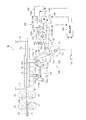
- FIG. 1 is a configuration diagram showing a main part of a sheet feeding apparatus according to an embodiment of the present invention in a side view.
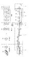
- FIG. 2 is a configuration diagram showing a box making machine according to an embodiment of the present invention in a side view.
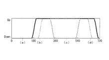
- FIG. 3 is a time chart for explaining the elevating / lowering operation of the sheet feeding apparatus according to the embodiment of the present invention.
- FIGS. 4A to 4D are side views of the main part of the sheet supply apparatus for explaining skip feed by the sheet supply apparatus according to the embodiment of the present invention.
- FIGS. 4A to 4D are respectively time charts of FIG. Corresponds to the time.
- FIGS. 1 to 3 and FIGS. 4A to 4D illustrate one embodiment of the present invention.
- the sheet supply apparatus according to the present embodiment is a corrugated cardboard sheet feeding apparatus (hereinafter also referred to as a sheet feeding apparatus or simply a sheet feeding apparatus) provided in a box making machine, and a sheet according to the present embodiment is used by using these.
- a corrugated sheet feeding device as a feeding device and a box making machine equipped with the corrugated sheet feeding device will be described.
- the sheet supply direction is the front
- the reverse direction is the rear
- the gravity direction vertical downward
- the reverse direction vertical upward
- FIG. 2 a process in which a plate-like corrugated cardboard sheet (hereinafter also simply referred to as a sheet) 10 a is processed into a box-making sheet material (corrugated cardboard box blank) 10 is shown separately from the apparatus configuration above the apparatus configuration. Yes.
- the box making machine is provided with a paper feeding unit 1, a printing unit 2, a paper discharging unit 3, a die cutting unit 4, a folding unit 5, and a counter ejector unit 6 in order from the upstream side.
- the printing unit 2, the paper discharge unit 3, the die cut unit 4, the folding unit 5, and the counter ejector unit 6 correspond to a sheet processing unit from which a sheet is sent out from the paper feeding unit 1.
- the printing unit 2 includes printing units 2a to 2d having a predetermined number of colors (here, four colors). In the printing unit 2, ink of each color is sequentially printed on the sheet 10a conveyed one by one by the conveying conveyor 20. To do.
- the sheet 10a printed by the printing unit 2 performs grooving and ruled lines. That is, the paper discharge unit 3 performs grooving and ruled lines, and the die cut unit 4 performs punching and punching of hand holes and air holes. Note that the die cutting unit 4 may perform grooving and ruled lines for creating a specially shaped box. Therefore, both the paper discharge unit 3 and the die cut unit 4 have a function of grooving and ruled lines.
- the sheet 10a that has been grooved or creased is glued to the glue margin at one end in the left-right direction, and the folding process is performed so that the left and right ends of the sheet 10a overlap on the back side (downward) The left and right ends of the folded sheet 10a are adhered with glue to form a box-making sheet material 10.
- the box-making sheet material 10 processed in the folding section 5 is loaded on the stacker while counting.
- the sheet material group 50 is shipped as one unit.
- the die cutting unit 4 does not have the paper discharge unit 3 and performs punching and punching of hand holes, air holes and the like, and also performs grooving and ruled lines to create the specially shaped box. Then, the sheet 10a that has been printed, grooved, and creased is introduced into the product production line, the articles are accumulated on the sheet 10a, and a box is formed and wrapped while being wrapped, Some machines are also called wraparound casers.
- the box-making sheet material 10 provided to such a machine is a sheet 10a that has been subjected to printing, grooving, and ruled lines processed in the die-cut unit 4.
- the box-making machine includes a folding unit 5 Is omitted, and the sheet 10a processed in the die cut unit 4 is sent to the counter ejector unit 6 for processing and shipment.
- the present invention can also be applied to such a box making machine.
- a corrugated sheet feeding apparatus 1M includes a sheet feeding table 11, a front guide 12, a backstop 13, feed rolls 14 and 14, and a plurality of wheels (also referred to as feeding rolls or sheet feeding rolls). ) 15 and a great (grid-like support plate) 16.
- the stacked sheets 10a are placed on the sheet feed table 11, and these sheets 10a have a leading edge in contact with the front guide 12 and a trailing edge in contact with the backstop 13, so that the conveying direction (feeding) Direction). Further, the position is regulated in the apparatus width direction (direction perpendicular to the paper feeding direction) by a side guide (not shown).
- the wheel 15 and the grate 16 are provided in front of the paper feed table 11 (paper feeding direction), and the front guide 12 has a lower edge in front of the wheel 15 and the grate 16 than the upper surface of the paper feed table 11. Equipped with about 1 sheet placed above. Further, feed rolls 14 and 14 that are paired up and down are provided in front of the front guide 11 so as to be separated from each other by a thickness of one sheet. Further, downstream of the feed rolls 14, 14, the printing unit 1 is equipped with a transport belt 21 and a transport roll 22 of the transport conveyor 20.
- the grid 16 is formed with a plurality of gaps arranged in, for example, a staggered pattern in the front-rear direction (paper feeding direction) and the left-right direction (device width direction).
- a plurality are arranged side by side in the direction and the left-right direction.
- the plurality of wheels 15 are set so that their upper edges are positioned slightly above the upper surface of the paper feed table 11.
- These wheels 15 are intermittently driven by a driving device (not shown) while interlocking with the main drive system of the box making machine.
- the intermittent driving of the wheel 15 means that the rotation is started from the stop state to the sheet passing speed, that is, the speed is accelerated to the same peripheral speed as the peripheral speed of the feed roll 14, and this speed is maintained.
- the driving is such that the operation of decelerating, stopping and maintaining the stopped state is repeated.
- the great 16 operates between the rising position where the upper surface of the great 16 is above the upper edge of the wheel 15 and the operation of the wheel 15 between the lowered position where the upper surface of the great 16 is below the upper edge of the wheel 15. It is driven up and down synchronously. Further, the great 16 brings the lowermost sheet 10a into contact with the upper edge of the wheel 15 when descending, and separates the lowermost sheet 10a from the upper edge of the wheel 15 when ascending.
- each wheel 15 starts to rotate and feeds the lowermost sheet 10a while accelerating to the sheet passing speed. 14 and 14 to pass.
- the great sheet 16 is raised so that the next sheet 10a does not come into contact with each wheel 15 to prevent the next sheet 10a from being fed.
- each wheel 15 decelerates and stops rotating. Such operations are repeated to feed paper one after another.
- the drive device 100 that drives the great 16 up and down as described above includes a link mechanism 110 that movably supports the great 16, a spring 120 that biases the great 16 to the lowered position, and the great 16.
- the great 16 includes a table portion 16a with which the lowermost sheet 10a abuts and a leg portion 16b protruding below the table portion 16a.
- a total of four leg portions 16b are provided on the front, rear, left and right sides.
- the table portion 16a is disposed horizontally, and each leg portion 16b protrudes vertically downward.
- a lower portion of each leg portion 16b is connected to the link mechanism 110. In FIG. 1, only the front side of the left and right leg portions 16b is shown.
- the link mechanism 110 has a pair of first links 111A and 111B having one end coupled to the leg portion 16b of the great 16 via a pin 111a and an intermediate portion rotatably positioned via the pin 111b.
- One end of the first link 111A, 111B is connected to the other end of the first link 111A, 111B via the pins 112a, 112a, and the other end of the first link 111A is connected to the extended portion 111c of the first link 111A via the pin 113a.
- a third link 113 coupled to the other end of the third link 113, and a fourth link 114 having one end coupled to the other end of the third link 113 via a pin 114a and an intermediate portion rotatably positioned via a pin 114b. I have.
- the one end side of 1st link 111A, 111B is arrange
- the second link 112 is arranged horizontally or substantially horizontally, and the great 16, the first links 111A and 111B, and the second link 112 constitute a parallel link.
- the third link 113 is arranged substantially vertically so that the force for raising and lowering the leg portion 16b can be transmitted efficiently.
- the 4th link 114 which is a rocking link where the intermediate part was rotatably fixed via the pin 114b is arrange
- link mechanisms 110 only one set of link mechanisms 110 is provided, and the left and right leg portions 16b are coupled to the respective pins 111a. Although it is configured to be driven up and down at the same time, the link mechanisms 110 may be provided on the left and right leg portions 16b, respectively, and operated in synchronization with each other.
- the spring 120 is engaged with the other end side of the fourth link 114 of the link mechanism 110 and applies a biasing force in the counterclockwise direction in FIG. 1 to the fourth link 114.
- the fourth link 114 receives a biasing force in the counterclockwise direction in FIG. 1
- one end side of the fourth link 114 is biased downward, and the fourth link 114 is connected to the fourth link 114 via the third link 113.
- the one link 111A receives a biasing force in the clockwise direction in FIG.
- this urging force is exerted, the leg portion 16b coupled to the first link 111A and the leg portion 16b coupled to the first link 111B interlocked with the first link 111A via the second link 112 are attached downward. Be forced. Accordingly, if no other force is applied, the spring 16 is lowered to the lowered position by the spring 120.
- the great elevating cam 130 is a rotating cam, and has a cam surface 131 that can abut on one side (here, the lower surface side) of the fourth link 114 of the link mechanism 110 from below. If the skip feed cam 140 and the swing cam 151 are not in contact with the fourth link 114, the cam surface 131 is always in contact with the fourth link 114 so as to oppose the urging force of the spring 120.
- the great lift cam 130 is formed with only one cam peak 132 from which the cam surface 131 protrudes, and the great 16 is raised in a rotational phase where the cam peak 132 abuts against the fourth link 114. The grate 16 is lowered in the rotational phase in contact with the fourth link 114.
- the great elevating cam 130 is rotationally driven by a drive mechanism (not shown) so as to interlock with the main drive system of the box making machine (the main drive system of the sheet processing unit), and is synchronized with the operation and stop of the wheel 15 as described above.
- the grate 16 is driven up and down between the raised position and the lowered position while rotating at a required timing.
- the skip feed cam 140 is a rotary cam, and has a cam surface 141 that can be brought into contact with the other side (here, the upper surface side) of the fourth link 114 of the link mechanism 110. Separately from the drive system, it is rotationally driven by an electric motor 143.
- the skip feed cam 140 is formed with only one cam peak portion 142 from which the cam surface 141 protrudes, and in the rotational phase in which the cam peak portion 142 abuts on the fourth link 114, the grate 16 is raised. However, in the rotational phase in contact with the fourth link 114, the grate 16 is lowered or does not prevent the grate 16 from being raised by the grate cam 130 or the swing cam 151.
- the operation of the skip feed cam 140 is controlled by the control device 160.
- the operation mode of the sheet feeding device 1M has a normal mode and a skip feed mode.
- the normal mode is selected and the transport direction is set.
- the skip feed mode is selected. This selection is performed by the control device 160 from the input order information or by an operator. Selection by the operator is performed by inputting selection information to the control device 160.
- the control device 160 controls the operation of the skip feed cam 140 through the electric motor 143. In the normal mode, the control device 160 stops the skip feed cam 140 in a state where the cam surface 141 is separated from the fourth link 114 of the link mechanism 110. In the feed mode, the skip feed cam 140 is operated. The operation timing when the skip feed cam 140 is activated will be described later.
- the air cylinder 150 is connected to a fixed cylinder main body 150a and a piston (not shown) that moves according to the air pressure in the air chamber (not shown) in the cylinder main body 150a, and is a piston whose projecting stroke from the cylinder main body 150a is changed.
- a rod (hereinafter simply referred to as a rod) 150b is provided, and the great 16 can be operated to the raised position regardless of the phases of the great lift cam 130 and the skip feed cam 140.
- the tip of the rod 150b is connected to a swing cam (movable part) 151 via an extension member 156 and an auxiliary link mechanism 155, and in accordance with the expansion / contraction of the air cylinder 150, that is, the change of the protruding stroke of the rod 150b, The phase of the swing cam 151 is changed.
- the swing cam 151 is rotatably supported at its intermediate portion by a pin 154 and can be brought into contact with the other side (the upper surface side in this case) of the other end side of the fourth link 114 of the link mechanism 110 on one side.
- a surface 152 is formed, and a lever portion 153 is extended on the other side.
- a protruding cam peak 152 a is formed on the cam surface 152, and when the cam peak 152 a comes into contact with the upper surface on the other end side of the fourth link 114, the grate 16 is raised.
- the auxiliary link mechanism 155 includes an auxiliary link 157 that is pin-coupled by pins 157a and 157b to the extension member 156 coupled to the tip of the rod 150b and the lever portion 153 of the swing cam 151, respectively. 1 contracts (the protrusion stroke of the rod 150b decreases), the cam crest 152a abuts against the upper surface on the other end side of the fourth link 114 as shown by the solid line in FIG.
- the air cylinder 150 contracts only when the device (box making machine) is stopped (including an emergency stop), reliably holds the great 16 in the raised position, and operates the device (box making machine). Sometimes it is extended so that it does not interfere with the operation of the other cams 130,140.
- the air cylinder 150 is configured to increase the protruding stroke of the rod 150b by supplying air and to decrease the protruding stroke of the rod 150b by discharging air. Therefore, when the apparatus is stopped, the air is discharged, so that the protruding stroke of the rod 150b is reduced, and the cam crest 152a of the swing cam 151 is on the other end side of the fourth link 114 as shown by the solid line in FIG. The grate 16 is securely held in the raised position.
- phase sensor (first phase detecting means) 171 for detecting the phase of the great lift cam 130 and a phase sensor (second phase detecting means) 172 for detecting the phase of the skip feed cam 140 are provided, and the control device 160 is provided with these.
- the phase of the electric motor 143 is controlled so that the skip feed cam 140 rotates at a predetermined phase as shown in FIG.
- the horizontal axis represents the rotational phase of each cam 130, 140
- the vertical axis represents the elevation level of the great 16 with respect to the rotational phase of each cam 130, 140.
- the broken line indicates the characteristics of the great lift cam 130
- the two-dot chain line indicates the characteristics of the skip feed cam 140
- the solid line indicates the characteristics of the combination of the great lift cam 130 and the skip feed cam 140.
- the great elevating cam 130 raises the great 16 once per one rotation (360 degrees) of the main drive system (in this case, the rotation phase is from about 180 degrees to the vicinity of 360 degrees).
- the skip feed cam 140 raises the great 16 once per two rotations (720 degrees) of the main drive system.
- the start timing when the skip feed cam 140 raises the great 16 is while the great lift cam 130 is raising the great 16 at a certain cycle, and the end timing when the skip feed cam 140 raises the great 16. Is during the period when the great lifting cam 130 raises the great 16 in the next cycle.
- both the great lift cam 130 and the skip feed cam 140 are in a state of lowering the great 16, and the upper surface of the great 16 has a top surface.
- the lower position is a height L2 lower than the upper edge height L1 of the wheel 15.
- the great lifting cam 130 is in a state of raising the great 16, and the upper surface of the great 16 has a height L3 higher than the upper edge height L1 of the wheel 15. Ascend to the ascending position.
- the great elevating cam 130 is still in the state where the great 16 is in the raised position (height L3).
- the skip feed cam 140 is As shown to 4B, it will be in the state which makes the great 16 a raise position.
- the timing of the lift operation of the skip feed cam 140 may be any time as long as the great lift cam 130 is in a state where the great 16 is in the lift position.
- the rotational phase of the main drive system comes to around 360 degrees, and the great lift cam 130 enters the state where the great 16 is lowered, but the skip feed cam 140 still raises the great 16 as shown in FIG. 4C. Since it is in a state of being held at the position (height L3), the great 16 is held at the raised position. Thereafter, when the rotational phase of the main drive system advances to around 540 degrees, the great lift cam 130 is in the state where the great 16 is in the raised position.
- the skip feed cam 140 is in a state in which the great 16 is lowered, but even at this time, the great lift cam 130 is still in the state in which the great 16 is raised. L3). Thereafter, the great lift cam 130 is in a state of lowering the great 16, and the great 16 is in a lowered state.
- the timing of the lowering operation of the skip feed cam 140 may be any as long as it is within a period in which the great lift cam 130 is in the state where the great 16 is in the raised position.
- an emergency stop switch (emergency stop command means) 173 is provided for issuing an emergency stop command to send out the sheet to the downstream side of the box making machine by the paper feeder 10M, and an emergency stop command can be issued by a switch operation by the operator. It is like that.
- the control device 160 controls the air cylinder 150 so as to hold the great 16 at the raised position. That is, the valve unit 158 of the air cylinder 150 is controlled so that the protruding stroke of the rod 150b is reduced by air discharge.
- the skip feed cam 140 has the cam surface 141 separated from the fourth link 114 of the link mechanism 110 by the control device 160, so the skip feed cam 140 does not affect the movement of the great 16.
- the great lift cam 130 causes the lowermost seat 10a to contact the lowermost seat 10a with the great 16 in the lowered position, so that each wheel 15 becomes the lowermost seat 10a. Is sent to the downstream side of the box making machine.
- the great lift cam 130 moves the lowermost seat 10a away from each wheel 15 with the great 16 as the raised position. 15 stops without affecting the sheet 10a.
- the control device 160 operates the skip feed cam 140, and the great lift cam 130 holds the great 16 in the raised position at a timing that does not place the great 16 in the raised position.
- Skip feed By controlling the skip feed cam 140 in this way, normal sheet supply (normal mode) and skip feed supply (skip feed mode) in which sheet supply is appropriately skipped with respect to this normal sheet supply are performed. can do.
- control device 160 controls the rotation phase of the skip feed cam 140 corresponding to the phase of the great lift cam 130 and the phase of the great lift cam 130 detected by the phase sensors 171 and 172 and the skip feed cam 140. By performing based on this phase, it is possible to appropriately perform skip feed in which the sheet feeding by the great lift cam 130 is paused every other time.
- the control device 160 controls the air cylinder 150 so as to hold the great 16 at the raised position. Specifically, the control device 160 controls the valve unit 158 of the air cylinder 150 so as to reduce the protruding stroke of the rod 150b by air discharge. As described above, the emergency stop by the air cylinder 150 can be surely performed by discharging the air, so that high reliability for the emergency stop can be ensured.
- the emergency stop air cylinder 150 and the swing cam 151 are provided, and the emergency stop is ensured by discharging the air to ensure high reliability for the emergency stop. That is, a state that does not affect the operation of the great 16 may be realized by air discharge, and may be urgently stopped by air supply. Although it is considered that the air supply during emergency stop is higher in reliability for emergency stop, it is possible to save the pump operating energy for generating air pressure because the air discharge state is normally set.
- an emergency stop operation can be performed relatively quickly by using an air cylinder
- other fluid pressure cylinders such as a hydraulic cylinder may be applied instead of such an air cylinder. If it is a fluid pressure cylinder as well as an air cylinder, it is easy to secure a supporting force for holding the grate 16 in the raised position, and it is easy to ensure reliability for emergency stop.
- the swing cam 151 is connected to the air cylinder 150 via the auxiliary link 155, and the swing cam 151 is swung by the expansion / contraction stroke of the air cylinder 150 to operate the link mechanism 110 to keep the great 16 in the raised state. Accordingly, the link mechanism 110 can be smoothly applied with the operating force that raises the great 16. However, the rod 150 b of the air cylinder 150 may directly contact the link mechanism 110 to hold the great 16 in the raised state. .
- the skip feed cam 140 may be used for emergency stop. Since the skip feed cam 140 is driven by an electric motor 143 that is independent of the main drive system, the skip feed cam 140 is fixed to a phase that holds the great 16 in the raised position for troubles of the main drive system. The sheet supply can be urgently stopped.
- the great 16 is moved up and down twice by the great lift cam 130, whereas the up and down movement of the great 16 of the skip feed cam 140 is performed only once.
- it is configured such that the up / down operation of the great 16 by the great up / down cam 130 is performed three times, whereas the up / down operation of the great 16 of the skip feed cam 140 is performed only once.
- each of the great elevating cam 130 and the skip feed cam 140 is configured to have only one cam peak portion, but may be configured to include a plurality of cam peak portions. For example, when two cam peaks 131 of the great lift cam 130 and one cam peak 141 of the skip feed cam 140 are provided, if both the cams 130 and 140 are rotated at a constant speed, the great lift cam 130 While the up / down operation of the great 16 is performed twice, the up / down operation of the great 16 of the skip feed cam 140 can be performed only once.
- the spring 120, the great lift cam 130, the skip feed cam 140, and the swing cam 151 of the air cylinder 150 are all arranged so as to contact or be able to contact the fourth link 114, the great The operation force of 16 is always performed from the fourth link 114 to the third link 113, and the drive mechanism is easily operated smoothly.
- the spring 120, the great lift cam 130, the skip feed cam 140, and the swing cam 151 of the air cylinder 150 may be in contact with each other so as to give a desired movement to any one of the link mechanisms 110. You may contact
- a box making machine is exemplified as the sheet processing apparatus
- a corrugated cardboard sheet feeding apparatus is exemplified as the sheet feeding apparatus.
- the sheet feeding apparatus of the present invention is not limited to the box making machine, and processes paperboard.
- the present invention can be widely applied to a sheet processing apparatus for processing a plate-like sheet such as a paper processing machine.
Abstract
緊急停止に対応可能で高速スキップフィード可能なシート供給装置の提供。 最下層のシート(10a)をシート加工部へ送り出すホイール(15)と、上昇位置でシート(10a)をホイール(15)から離隔させ下降位置でシート(10a)をホイール(15)に接触させるグレート(16)と、グレート(16)を昇降駆動する駆動装置(100)と、を有し、駆動装置(100)は、グレート(16)を可動に支持するリンク機構(110)と、グレート(16)を下降位置に付勢するバネ(120)と、グレート(16)を周期的に昇降駆動するグレート昇降カム(130)と、グレート昇降カム(130)の駆動系とは別に制御装置の制御により駆動され、グレート昇降カム(130)がグレート(16)を上昇位置にしない位相になるタイミングでグレート(16)を上昇位置に保持してシート(10a)をスキップフィードさせるスキップフィードカム(140)を有する。
Description
本発明は、製函機等の紙工機械の給紙装置に用いて好適のシート供給装置に関するものである。
シート状の紙から紙製品を製造する紙工機械など、シート状の素材(シート状ワーク、以下、単にシートとも言う)を何らかの製品に加工するシート加工装置において、上流部分にシートを供給するシート供給装置を装備したものがある。例えば、代表的な紙工機械である製函機の場合、上流側から、給紙部,印刷部,排紙部,ダイカット部,フォルディング部,カウンタエジェクタ部が順に設けられ、給紙部から供給されるシート状ワークである段ボールシート(単に、シートとも言う)を加工して段ボール箱を製造する。
この製函機の給紙部には、シート供給装置に相当する段ボールシート給紙装置が装備される。この段ボールシート給紙装置には、ホイール(送り出しロール又は給紙ロールとも呼ぶ)とグレート(格子状の支持板)とを用いたものがある。つまり、積層されたシートが載せられる給紙テーブルの前方(給紙する方向)の部分には、ホイールとグレートとが装備され、これらの前方には、フロントガイドが下縁を給紙テーブルの上面よりもシート1枚分程度上方に配置させて装備される。また、フロントガイドの前方には上下に対をなすフィードロールがシート1枚分の厚さ程度離隔して装備される。
ホイールは、その上縁が給紙テーブルの上面よりも僅かに上方に位置するように配置されており、このホイールは、間欠的に駆動され、停止状態から回転を開始して通紙速度まで、即ち、フィードロールの周速と同一周速に達するまで加速し、その後、減速して停止するといった動作を繰り返す。グレートは格子状に形成されその隙間にホイールが配置される。グレートの上面はホイールの上縁よりも上方の位置と下方の位置との間で、ホイールの作動と同期して昇降駆動され、下降時には最下層のシートをホイールの上縁に接触させ、上昇時には最下層のシートをホイールの上縁から離隔させる。
このような段ボールシート給紙装置では、給紙はホイールの回転とグレートの昇降動作とが連携することで行なわれる。つまり、まず、グレートが下がり、最下層のシートをホイールと接触させる。この状態で、ホイールが回転開始し、通紙速度まで加速してフィードロールに受け渡す。ここで、グレートが上がり、次のシートとホイールが接触しないようにして、次のシートが給紙されるのを防ぐ。この間に、ホイールが減速し回転停止する。このような動作を繰り返して次々に給紙する。
段ボールシート給紙装置による給紙は、基本的には主駆動系に連動して行われ、例えば印刷部の印刷シリンダが1回転すると1回だけ給紙するようになっているが、例えば搬送方向に長い段ボールシートを加工する場合、印刷部の印刷シリンダの2回転につき1回だけ給紙する、いわゆる、スキップフィードを行なう場合がある。このスキップフィードは、グレートの昇降動作を変更することにより行なうことができる。
このようなグレートの昇降動作を変更可能にする技術として、例えば、特許文献1には、1回の機械周期につき1回だけグレートを上昇させる単一モードカムと、1回の機械周期につき複数回グレートを上昇させる多数モードカムとを同軸に備えると共に、これらのカムとは別に、エアシリンダを備えたものが開示されている。この技術では、単一モードカムがグレートを上昇させない位置(つまり、グレートを下降状態にする位置)にあっても、エアシリンダによりグレートを上昇させることができ、スキップフィードを行なうことができる。
また、特許文献2~6には、固定カムと可動カムとを同軸に備え、これらの固定カムと可動カムとの組み合わせで規定されるタイミングでグレートを上昇及び下降させるようにして、グレートの昇降動作を変更する構成が記載されており、可動カムの位相調整によりグレートの上昇期間を長くすることにより、スキップフィードを行なうことができる。
ところで、例えば主駆動系に故障が発生して給紙を停止したい場合が発生しうる。特許文献2~6の技術は、同軸に備えた固定カムと可動カムとのうち可動カムの位相調整によりスキップフィードを行なうものであるが、固定カムと可動カムとを支持する軸の駆動系が故障した場合には、これとは別に給紙を緊急停止するための何らかの手段を装備することが必要になる。
一方、特許文献1の技術は、主駆動系とは別にエアシリンダによりグレートを上昇させてスキップフィードを行なう構成を備えるため、エアシリンダによりグレートを上昇させて給紙を緊急停止することができる。しかし、エアシリンダの場合、伸縮速度の限界に達しやすいこと及びエアの供給が間に合わないことから高速でスキップフィードを行なうことは困難と考えられる。近年、製函機をはじめとしたシート加工装置では、製造ラインの高速化が求められているが、エアシリンダを用いたスキップフィードではこの要求に十分に答えられない。
本発明は、上記の課題に鑑み創案されたもので、主駆動系に故障が発生した際の緊急停止にも対応可能であり、且つ、高速でスキップフィードを行なうことができるようにしたシート供給装置を提供することを目的とする。
(1)本発明のシート供給装置は、作動と停止とを繰り返し、作動時には積層されたシートのうちの最下層のシートをシート加工部へ送り出す複数のホイールと、上昇位置で前記最下層のシートを前記各ホイールから離隔させ下降位置で前記最下層のシートを前記複数の各ホイールに接触させるグレートと、前記グレートを前記各ホイールの作動と連携して昇降駆動する駆動装置と、を有し、前記駆動装置は、前記グレートを可動に支持するリンク機構と、前記リンク機構の何れかのリンクに係合し前記グレートを前記下降位置に付勢するバネと、前記リンク機構の何れかのリンクに当接可能なカム面を有し、前記グレートを、前記各ホイールの停止時には前記上昇位置に前記各ホイールの作動時には前記下降位置にと周期的に昇降駆動するグレート昇降カムと、前記リンク機構の何れかのリンクに当接可能なカム面を有し、前記グレート昇降カムの駆動系とは別に電動モータにより駆動され、スキップフィードモード時に作動し、前記グレート昇降カムが前記グレートを前記上昇位置にしない位相になるタイミングで前記グレートを前記上昇位置に保持して最下層のシートをスキップフィードさせるスキップフィードカムと、通常モード時には前記スキップフィードカムをそのカム面が前記リンク機構のリンクから離隔する状態で停止させ、スキップフィードモード時には前記スキップフィードカムを作動させる制御手段と、を有している。
(2)前記グレート昇降カム及び前記スキップフィードカムは何れも回転カムであって、前記グレート昇降カムは前記シート加工部の主駆動系と連動して回転し、前記スキップフィードカムを回転駆動する電動モータを有し、前記制御手段は、前記スキップフィードカムを回転駆動する前記電動モータの回転を前記主駆動系の動作に基づいて制御することが好ましい。
(3)前記制御手段は、前記グレート昇降カムの前記グレートの昇降動作が2回行なわれるのに対して、前記スキップフィードカムの前記グレートの昇降動作が1回だけ行なわれるように前記電動モータの回転を制御することが好ましい。
(4)さらに、前記グレート昇降カム及び前記スキップフィードカムは、何れも、対応する前記リンク機構のリンクに当接して前記グレートを上昇操作するカム山部を1つだけ有し、前記制御手段は、前記グレート昇降カムの1回転に対して前記スキップフィードカムが1/2回転するように前記電動モータの回転を制御することが好ましい。
(5)前記グレート昇降カムの位相を検知する第1位相検知手段及び前記スキップフィードカムの位相を検知する第2位相検知手段を有し、前記制御手段は、前記第1位相検知手段及び前記第2位相検知の検知情報に基づいて、前記グレート昇降カムの位相に対して前記スキップフィードカムが所定の位相で回転するように前記電動モータの位相を制御することが好ましい。
(6)前記シート加工部へのシートの送り出しを緊急停止指令する緊急停止指令手段を有し、前記制御手段は、前記緊急停止指令手段により緊急停止指令がなされると、前記スキップフィードカムを、前記グレートを前記上昇位置にする位相で停止させることが好ましい。
(7)あるいは、前記グレート昇降カム及び前記スキップフィードカムの各位相に関わらず、可動部が前記リンク機構の何れかのリンクに当接して前記グレートを前記上昇位置に操作可能なエア流体圧シリンダと、前記シート加工部へのシートの送り出しを緊急停止指令する緊急停止指令手段と、を有し、前記制御手段は、通常時は前記可動部を前記リンク機構の何れかのリンクに対して離隔させ、前記緊急停止指令手段により緊急停止指令がなされると前記可動部を前記リンク機構の何れかのリンクに当接させて前記グレートを前記上昇位置にするように前記エア流体圧シリンダを制御することが好ましい。なお、流体圧シリンダにはエアシリンダが好ましい。
(8)この場合、前記エア流体圧シリンダの前記可動部は、前記エア流体圧シリンダに接続された補助リンク機構と、前記補助リンク機構に接続されて前記エア流体圧シリンダの伸縮に伴って揺動する揺動カムとを有し、前記揺動カムが前記リンク機構の何れかのリンクに当接可能に配置されていることが好ましい。
(9)前記バネ,前記グレート昇降カム及び前記スキップフィードカム、又は、前記バネ,前記グレート昇降カム,前記スキップフィードカム及び前記エア流体圧シリンダの前記可動部は、何れも、前記リンク機構の1つのリンクに当接することが好ましい。
(10)この場合、前記1つのリンクは、中間部を回転自在に支持された揺動リンクであって、前記揺動リンクの一端側の一側に前記グレート昇降カムが当接し、前記揺動リンクの他端側の他側に、前記スキップフィードカム、又は、前記スキップフィードカム及び前記エア流体圧シリンダの前記可動部が当接することが好ましい。
(11)前記シート加工部は前記段ボールシートから段ボール箱を加工する製函機の各加工部であって、段ボールシート給紙装置として構成されていることが好ましい。
本発明のシート供給装置によれば、複数のホイールは作動と停止とを繰り返し、グレートは各ホイールの作動と連携して昇降する。通常モード時には、スキップフィードカムのカム面をリンク機構のリンクから離隔させておき、各ホイールの作動時には、グレート昇降カムがグレートを下降位置にして最下層のシートを各ホイールに接触させ、各ホイールが最下層のシートをシート加工部へ送り出し、各ホイールの停止時には、グレート昇降カムがグレートを上昇位置にして最下層のシートを各ホイールから離隔させ、各ホイールはシートに影響することなく停止する。一方、スキップフィードモード時には、スキップフィードカムを作動させ、グレート昇降カムがグレートを上昇位置にしない位相になるタイミングでグレートを上昇位置に保持して最下層のシートをスキップフィードさせる。このようにスキップフィードカムを制御することで、通常のシート供給と、この通常のシート供給に対してシート供給を適宜スキップさせたスキップフィード供給とを実施することができる。
このスキップフィードカムは、グレート昇降カムの駆動系とは別に電動モータにより駆動されるので、緊急時には、このスキップフィードカムを作動させてグレートを上昇位置に保持する状態にしておくことでシートの供給を停止することができる。また、流体圧シリンダの伸縮動作とエア供給の応答動作よりも電動モータによる回転動作の方が高速作動に対応しやすいので、シート加工部の高速化に対応した高速スキップフィードを行なうこともできる。
以下、図面により、本発明の実施の形態を説明する。
以下に示す各実施形態はあくまでも例示に過ぎず、以下の実施形態で明示しない種々の変形や技術の適用を排除する意図はない。以下の実施形態の各構成は、それらの趣旨を逸脱しない範囲で種々変形して実施することができるとともに、必要に応じて取捨選択することができ、あるいは適宜組み合わせることが可能である。
以下に示す各実施形態はあくまでも例示に過ぎず、以下の実施形態で明示しない種々の変形や技術の適用を排除する意図はない。以下の実施形態の各構成は、それらの趣旨を逸脱しない範囲で種々変形して実施することができるとともに、必要に応じて取捨選択することができ、あるいは適宜組み合わせることが可能である。
図1~図3及び図4A~図4Dは本発明の一実施形態を説明するものである。本実施形態にかかるシート供給装置は、製函機に装備される段ボールシート給紙装置(以下、シート給紙装置又は単に給紙装置とも言う)であり、これらを用いて本実施形態にかかるシート供給装置としての段ボールシート給紙装置及びこの段ボールシート給紙装置を備えた製函機について説明する。なお、下記の説明では、シートの供給方向を前方、その逆方向を後方とし、重力方向(鉛直下方)を下方、その逆方向(鉛直上方)を上方とする。
〔製函機〕
まず、本実施形態にかかる製函機について図2を参照して説明する。
図2では、板状の段ボールシート(以下、単にシートとも言う)10aが製函用シート材(段ボール箱用ブランク)10に加工される工程を装置構成の上方に装置構成とは分けて示している。図2に示すように、この製函機は、上流側から、給紙部1,印刷部2,排紙部3,ダイカット部4,フォルディング部5,カウンタエジェクタ部6が順に設けられている。なお、印刷部2,排紙部3,ダイカット部4,フォルディング部5,カウンタエジェクタ部6は、給紙部1からシートが送り出されるシート加工部に相当する。
まず、本実施形態にかかる製函機について図2を参照して説明する。
図2では、板状の段ボールシート(以下、単にシートとも言う)10aが製函用シート材(段ボール箱用ブランク)10に加工される工程を装置構成の上方に装置構成とは分けて示している。図2に示すように、この製函機は、上流側から、給紙部1,印刷部2,排紙部3,ダイカット部4,フォルディング部5,カウンタエジェクタ部6が順に設けられている。なお、印刷部2,排紙部3,ダイカット部4,フォルディング部5,カウンタエジェクタ部6は、給紙部1からシートが送り出されるシート加工部に相当する。
給紙部1では、シート10aが多数積載された状態で搬入され、このシート10aを1枚ずつ印刷部2に供給する。
印刷部2は、所定の色数(ここでは、4色)の印刷ユニット2a~2dからなり、印刷部2では、搬送コンベア20によって1枚ずつ搬送されるシート10aに、各色のインキを順次印刷する。
印刷部2は、所定の色数(ここでは、4色)の印刷ユニット2a~2dからなり、印刷部2では、搬送コンベア20によって1枚ずつ搬送されるシート10aに、各色のインキを順次印刷する。
排紙部3及びダイカット部4では、印刷部2で印刷されたシート10aに、溝切りや罫線入れを行なう。つまり、排紙部3では溝切り,罫線入れを行い、ダイカット部4では手穴,空気穴等の孔開け及び打ち抜きを行なう。なお、ダイカット部4では、特殊な形状の箱を作成するための溝切り,罫線入れを行なうこともある。したがって、排紙部3及びダイカット部4のどちらも溝切り,罫線入れを行なう機能を有している。
そして、フォルディング部5では、溝切りや罫線入れをされたシート10aの左右方向一端の糊代に糊付けして、シート10aの左右両端部が裏側(下方)で重合するように、折り曲げ加工を行なって、折り曲げられたシート10aの左右両端部を糊によって接着して製函用シート材10とする。
カウンタエジェクタ部6では、フォルディング部5で加工された製函用シート材10を計数しながら、スタッカに積載する。そして、所定枚数の製函用シート材10が積み上げられたら、このシート材群50を1単位として出荷する。
なお、排紙部3を有さず、ダイカット部4において、手穴,空気穴等の孔開け及び打ち抜きを行なうと共に、上記の特殊な形状の箱を作成するための溝切り,罫線入れを行なって、印刷及び溝切りや罫線入れをされたシート10aを製品の製造ラインに導入して、シート10aの上に物品を集積して載せ、これを包み込むようにしながら箱を成形して包装する、ラップアラウンド・ケーサーとも呼ばれる機械もある。このような機械に提供する製函用シート材10は、ダイカット部4で処理した段階の印刷及び溝切りや罫線入れをされたシート10aであり、この場合、製函機は、フォルディング部5が省略され、ダイカット部4で処理したシート10aをカウンタエジェクタ部6に送って処理して出荷するものとなる。本発明はこうした製函機にも適用することができる。
〔段ボールシート給紙装置〕
次に、給紙部1に装備される段ボールシート給紙装置1Mを説明する。
図1に示すように、段ボールシート給紙装置1Mは、給紙テーブル11と、フロントガイド12と、バックストップ13と、フィードロール14,14と、複数のホイール(送り出しロール又は給紙ロールとも呼ぶ)15及びグレート(格子状の支持板)16とを備えている。
次に、給紙部1に装備される段ボールシート給紙装置1Mを説明する。
図1に示すように、段ボールシート給紙装置1Mは、給紙テーブル11と、フロントガイド12と、バックストップ13と、フィードロール14,14と、複数のホイール(送り出しロール又は給紙ロールとも呼ぶ)15及びグレート(格子状の支持板)16とを備えている。
給紙テーブル11の上に積層されたシート10aが載せられ、これらのシート10aは、前縁をフロントガイド12に当接させ、後縁をバックストップ13に当接させて、搬送方向(給紙方向)に位置を規制される。また、図示しないサイドガイドによって装置幅方向(給紙方向と直行する方向)に位置を規制される。
ホイール15及びグレート16は、給紙テーブル11の前方(給紙する方向)の部分に装備され、ホイール15及びグレート16の前方に、フロントガイド12が下縁を給紙テーブル11の上面よりもシート1枚分程度上方に配置させて装備される。また、フロントガイド11の前方に上下に対をなすフィードロール14,14が互いにシート1枚分の厚さ程度離隔して装備される。また、フィードロール14,14の下流には、印刷部1に搬送コンベア20の搬送ベルト21及び搬送ロール22等が装備されている。
格子状に形成されるグレート16には、前後方向(給紙方向)及び左右方向(装置幅方向)に例えば千鳥状に並んだ複数の隙間が形成され、ホイール15は、グレート16の隙間に前後方向及び左右方向に並んで複数配置されている。これらの複数のホイール15は、その上縁が給紙テーブル11の上面よりも僅かに上方に位置するように位置設定されている。
これらのホイール15は、図示しない駆動装置によって製函機の主駆動系と連動しながら間欠的に駆動される。このホイール15の間欠的な駆動とは、停止状態から回転を開始して通紙速度まで、即ち、フィードロール14の周速と同一周速に達するまで加速してこの速度を維持し、その後、減速して停止し停止状態を維持するといった動作を繰り返すような駆動である。
グレート16は、グレート16の上面がホイール15の上縁よりも上方となる上昇位置と、グレート16の上面がホイール15の上縁よりも下方となる下降位置との間で、ホイール15の作動と同期して昇降駆動される。また、グレート16は、下降時には最下層のシート10aをホイール15の上縁に接触させ、上昇時には最下層のシート10aをホイール15の上縁から離隔させる。
つまり、まず、グレート16が下がり、最下層のシート10aを各ホイール15と接触させた状態で、各ホイール15が回転開始し、通紙速度まで加速しながら最下層のシート10aを送り出してフィードロール14,14に受け渡す。ここで、グレート16が上がり、次のシート10aと各ホイール15が接触しないようにして、次のシート10aが給紙されるのを防ぐ。この間に、各ホイール15が減速し回転停止する。このような動作を繰り返して次々に給紙するようになっている。
グレート16をこのように昇降駆動する駆動装置100は、図1に示すように、グレート16を可動に支持するリンク機構110と、グレート16を下降位置に付勢するバネ120と、グレート16を周期的に昇降駆動するグレート昇降カム130と、シート10aをスキップフィードさせるスキップフィードカム140と、エアシリンダ150で駆動される揺動カム151と、スキップフィードカム140及びエアシリンダ150を制御する制御装置(制御手段)160と、を有している。
グレート16は、最下層のシート10aが当接するテーブル部16aと、テーブル部16aの下方に突出した脚部16bとを備えている。脚部16bは、前後左右に計4本備えられている。テーブル部16aは水平に配置され、各脚部16bは鉛直下方に突出している。各脚部16bの下部がリンク機構110に接続されている。なお、図1では左右の脚部16bのうち手前側のもののみを示している。
リンク機構110は、一端がピン111aを介してグレート16の脚部16bを結合されて中間部がピン111bを介して回転可能に位置固定された一対の第1リンク111A,111Bと、一対の第1リンク111A,111Bの下方に延びた他端をピン112a,112aを介して互いに結合する第2リンク112と、一方の第1リンク111Aの一端側の延設部111cにピン113aを介して一端が結合された第3リンク113と、第3リンク113の他端にピン114aを介して一端が結合されて中間部がピン114bを介して回転可能に位置固定された第4リンク114と、を備えている。
なお、第1リンク111A,111Bの一端側は略水平に配置され、脚部16bを効率よく昇降できるようになっている。また、第2リンク112は水平又は略水平に配置され、グレート16,第1リンク111A,111B及び第2リンク112は平行リンクを構成している。また、第3リンク113は略鉛直に配置され、脚部16bを昇降させる力を効率よく伝達できるようになっている。そして、中間部がピン114bを介して回転可能に位置固定された揺動リンクである第4リンク114は略水平に配置され、脚部16bを昇降させる力を、第3リンク113を介して効率よく伝達できるようになっている。
また、ここでは、リンク機構110は、1組のみ設けられ、各ピン111aにそれぞれ左右の脚部16bが結合され、前後それぞれにおいて左右に配置された各脚部16bが1組のリンク機構110によって同時に昇降駆動するように構成されているが、リンク機構110を左右の脚部16bにそれぞれ設けて、これらを同期して作動させるようにしてもよい。
バネ120は、リンク機構110の第4リンク114の他端側に係合し、第4リンク114に図1中反時計回り方向への付勢力を付与している。第4リンク114が図1中反時計回り方向への付勢力を受けると、第4リンク114の一端側は下方に付勢され、第4リンク114に第3リンク113を介して接続された第1リンク111Aは図1中時計回り方向への付勢力を受ける。この付勢力が発揮されると、第1リンク111Aに結合された脚部16b及び第2リンク112を介して第1リンク111Aと連動する第1リンク111Bに結合された脚部16bは下方に付勢される。これにより、他の力が働かなければ、バネ120によってグレート16は下降位置に下降される。
グレート昇降カム130は、回転カムであり、リンク機構110の第4リンク114の一端側の一側(ここでは、下面側)に下方から当接可能なカム面131を有している。スキップフィードカム140及び揺動カム151が第4リンク114に当接していなければ、カム面131はバネ120の付勢力に対抗するように第4リンク114に常に当接する。グレート昇降カム130にはカム面131が突出したカム山部132が1つだけ形成され、カム山部132が第4リンク114に当接する回転位相ではグレート16は上昇され、カム山部132以外が第4リンク114に当接する回転位相ではグレート16は下降される。
グレート昇降カム130は、製函機の主駆動系(シート加工部の主駆動系)と連動するように図示しない駆動機構により回転駆動され、上述のように、ホイール15の作動及び停止と同期した所要のタイミングで回転しながらグレート16を上昇位置と下降位置との間で昇降駆動する。
スキップフィードカム140は、回転カムであり、リンク機構110の第4リンク114の他端側の他側(ここでは、上面側)に当接可能なカム面141を有し、グレート昇降カム130の駆動系とは別に電動モータ143により回転駆動される。スキップフィードカム140には、カム面141が突出したカム山部142が1つだけ形成され、カム山部142が第4リンク114に当接する回転位相ではグレート16は上昇され、カム山部142以外が第4リンク114に当接する回転位相ではグレート16は下降されるか、或いは、グレート昇降カム130や揺動カム151によるグレート16の上昇を妨げない。
このスキップフィードカム140は、制御装置160によって作動を制御される。なお、給紙装置1Mの作動モードとして、通常モードとスキップフィードモードとを有し、搬送方向に一定長さ以下の比較的短い段ボールシートを加工する場合には通常モードを選択し、搬送方向に一定長さ以下の比較的長い段ボールシートを加工する場合にはスキップフィードモードを選択する。この選択は、入力されたオーダ情報から制御装置160により行なわれるか、或いは、オペレータによって行われる。オペレータによる選択は選択情報が制御装置160に入力され行われる。
制御装置160は、電動モータ143を通じてスキップフィードカム140の作動を制御するが、通常モード時にはスキップフィードカム140をそのカム面141がリンク機構110の第4リンク114から離隔する状態で停止させ、スキップフィードモード時にはスキップフィードカム140を作動させる。なお、スキップフィードカム140の作動時の動作タイミングについては後述する。
エアシリンダ150は、固定されたシリンダ本体150aと、シリンダ本体150a内の図示しなエア室内のエア圧に応じて移動する図示しないピストンに接続されてシリンダ本体150aからの突出ストロークを変更されるピストンロッド(以下、単に、ロッドとも言う)150bとを備え、グレート昇降カム130及びスキップフィードカム140の各位相に関わらず、グレート16を上昇位置に操作することが可能となっている。ロッド150bの先端部は、延長部材156,補助リンク機構155を介して、揺動カム(可動部)151が接続され、エアシリンダ150の伸縮、即ち、ロッド150bの突出ストロークの変更に応じて、揺動カム151の位相が変更される。
揺動カム151は、中間部をピン154によって回転自在に支持され、一側にはリンク機構110の第4リンク114の他端側の他側(ここでは、上面側)に当接可能なカム面152が形成され、他側にはレバー部153が延長されている。カム面152には突出したカム山部152aが形成され、カム山部152aが第4リンク114の他端側の上面に当接すると、グレート16は上昇される。
補助リンク機構155は、ロッド150bの先端部に結合された延長部材156と揺動カム151のレバー部153とにそれぞれピン157a,157bによりピン結合された補助リンク157を備えており、エアシリンダ150が収縮する(ロッド150bの突出ストロークが小さくなる)と図1に実線で示すようにカム山部152aが第4リンク114の他端側の上面に当接してグレート16を上昇位置にする。
一方、エアシリンダ150が伸張する(ロッド150bの突出ストロークが大きくなる)と図1に二点鎖線で示すようにカム面152が第4リンク114の他端側の上面から離隔して、グレート昇降カム130やスキップフィードカム140の作動を妨げない。
本実施形態では、エアシリンダ150は、装置(製函機)の停止時(緊急停止時を含む)にのみ収縮し、グレート16を確実に上昇位置に保持し、装置(製函機)の作動時には伸張して、他のカム130,140の作動を妨げないように使用される。
本実施形態では、エアシリンダ150は、装置(製函機)の停止時(緊急停止時を含む)にのみ収縮し、グレート16を確実に上昇位置に保持し、装置(製函機)の作動時には伸張して、他のカム130,140の作動を妨げないように使用される。
また、エアシリンダ150は、エア供給によりロッド150bの突出ストロークを大きくし、エア排出によりロッド150bの突出ストロークを小さくするように構成されている。したがって、装置の停止時には、エア排出がされるためロッド150bの突出ストロークが小さくなって、揺動カム151のカム山部152aが、図1に実線で示すように第4リンク114の他端側の上面に当接するようになってグレート16を確実に上昇位置に保持する。
〔スキップフィードカムの動作タイミング〕
ここで、スキップフィードカム140の動作タイミングを説明する。前述のように、グレート昇降カム130の駆動系とは別に電動モータ143により回転駆動されるが、電動モータ143(具体的には、電動モータ143を駆動するモータドライバ144)は、制御装置160によって作動を制御される。
ここで、スキップフィードカム140の動作タイミングを説明する。前述のように、グレート昇降カム130の駆動系とは別に電動モータ143により回転駆動されるが、電動モータ143(具体的には、電動モータ143を駆動するモータドライバ144)は、制御装置160によって作動を制御される。
つまり、グレート昇降カム130の位相を検知する位相センサ(第1位相検知手段)171及びスキップフィードカム140の位相を検知する位相センサ(第2位相検知手段)172が装備され、制御装置160はこれらの位相センサ171,172の検出情報を受けて、グレート昇降カム130の位相に対してスキップフィードカム140が図3に示すような所定の位相で回転するように電動モータ143の位相を制御する。
図3において、横軸は各カム130,140の回転位相を示し、縦軸は各カム130,140の回転位相に対するグレート16の昇降レベルで示す。また、破線はグレート昇降カム130の特性を示し、二点鎖線はスキップフィードカム140の特性を示し、実線はグレート昇降カム130とスキップフィードカム140との組み合わせによる特性を示す。
図3に破線で示すように、グレート昇降カム130は主駆動系の1回転(360度)につき1度(ここでは、回転位相が180度付近から360度の手前付近まで)グレート16を上昇させるが、図3に二点鎖線で示すように、スキップフィードカム140は主駆動系の2回転(720度)につき1度グレート16を上昇させる。このスキップフィードカム140がグレート16を上昇させる際の開始タイミングは、グレート昇降カム130がある周期でグレート16を上昇させている間であり、スキップフィードカム140がグレート16を上昇させる際の終了タイミングは、グレート昇降カム130が次の周期でグレート16を上昇させている間である。
つまり、主駆動系の回転位相が(a)の時点では、図4Aに示すように、グレート昇降カム130及びスキップフィードカム140は何れもグレート16を下降させる状態にあり、グレート16はその上面がホイール15の上縁高さL1よりも低い高さL2となる下降位置となる。その後、主駆動系の回転位相が180度の付近まで進むと、グレート昇降カム130はグレート16を上昇させる状態となり、グレート16はその上面がホイール15の上縁高さL1よりも高い高さL3となる上昇位置に上昇する。
その後、主駆動系の回転位相が(b)に来る時点では、グレート昇降カム130は依然としてグレート16を上昇位置(高さL3)とする状態にあり、このときに、スキップフィードカム140が、図4Bに示すように、グレート16を上昇位置とする状態となる。なお、このスキップフィードカム140の上昇作動のタイミングは、グレート昇降カム130がグレート16を上昇位置とする状態にある期間内であればいずれでもよい。
その後、主駆動系の回転位相が360度付近に来て、グレート昇降カム130はグレート16を下降位置とする状態となるが、図4Cに示すように、スキップフィードカム140は依然としてグレート16を上昇位置(高さL3)に保持する状態にあるため、グレート16は上昇位置に保持される。その後、主駆動系の回転位相が540度の付近まで進むと、グレート昇降カム130はグレート16を上昇位置とする状態となる。
その後、図4Dに示すように、スキップフィードカム140はグレート16を下降させる状態となるが、この時点でもグレート昇降カム130は依然としてグレート16を上昇させる状態にあるため、グレート16は上昇位置(高さL3)に保持される。その後、グレート昇降カム130がグレート16を下降させる状態となって、グレート16は下降状態となる。なお、スキップフィードカム140の下降作動のタイミングは、グレート昇降カム130がグレート16を上昇位置とする状態にある期間内であればいずれでもよい。
〔緊急停止〕
さらに、給紙装置10Mによる製函機の下流側へのシートの送り出しを緊急停止指令する緊急停止スイッチ(緊急停止指令手段)173が装備されており、オペレータによるスイッチ操作で緊急停止指令を行なえるようになっている。制御装置160は緊急停止スイッチ173が操作されると、エアシリンダ150を、グレート16を上昇位置に保持するように制御する。つまり、エア排出によりロッド150bの突出ストロークを小さくするようにエアシリンダ150のバルブユニット158を制御する。
さらに、給紙装置10Mによる製函機の下流側へのシートの送り出しを緊急停止指令する緊急停止スイッチ(緊急停止指令手段)173が装備されており、オペレータによるスイッチ操作で緊急停止指令を行なえるようになっている。制御装置160は緊急停止スイッチ173が操作されると、エアシリンダ150を、グレート16を上昇位置に保持するように制御する。つまり、エア排出によりロッド150bの突出ストロークを小さくするようにエアシリンダ150のバルブユニット158を制御する。
〔作用及び効果〕
本発明の一実施形態にかかるシート供給装置及びそれを備えた製函機は、上述のように構成されるので、複数のホイール15は作動と停止とを繰り返し、グレート16は各ホイール15の作動と連携して昇降する。
本発明の一実施形態にかかるシート供給装置及びそれを備えた製函機は、上述のように構成されるので、複数のホイール15は作動と停止とを繰り返し、グレート16は各ホイール15の作動と連携して昇降する。
通常モード時には、制御装置160によりスキップフィードカム140はカム面141をリンク機構110の第4リンク114から離隔されているので、スキップフィードカム140はグレート16の動きに影響しない。そして、各ホイール15の作動時(回転時)には、グレート昇降カム130がグレート16を下降位置にして最下層のシート10aを各ホイール15に接触させるため、各ホイール15が最下層のシート10aを製函機の下流側へ送り出す。各ホイール15の停止時(送り出し速度からの減速時及びその後の停止時)には、グレート昇降カム130がグレート16を上昇位置にして最下層のシート10aを各ホイール15から離隔させるため、各ホイール15はシート10aに影響することなく停止する。
一方、スキップフィードモード時には、制御装置160がスキップフィードカム140を作動させ、グレート昇降カム130がグレート16を上昇位置にしない位相になるタイミングでグレート16を上昇位置に保持して最下層のシート10aをスキップフィードさせる。このようにスキップフィードカム140を制御することで、通常のシート供給(通常モード)と、この通常のシート供給に対してシート供給を適宜スキップさせたスキップフィード供給(スキップフィードモード)と、を実施することができる。
また、制御装置160は、このようなグレート昇降カム130の位相に対応したスキップフィードカム140の回転位相の制御を、位相センサ171,172で検出されるグレート昇降カム130の位相及びスキップフィードカム140の位相に基づいて行なうことで、グレート昇降カム130によるシート供給を一回おきに休止させるスキップフィードを適切に行なうことができる。
さらに、緊急停止指令が成されると、制御装置160は、グレート16を上昇位置に保持するようにエアシリンダ150を制御する。具体的には、制御装置160は、エア排出によりロッド150bの突出ストロークを小さくするようにエアシリンダ150のバルブユニット158を制御する。このようにエアシリンダ150による緊急停止は、エア排出により確実に行なえるので、緊急停止にかかる高い信頼性を確保することができる。
〔その他〕
以上、本発明の実施形態を説明したが、本発明は上述の実施の形態に限定されるものではなく、本発明の趣旨を逸脱しない範囲で種々変形して実施することができる。
以上、本発明の実施形態を説明したが、本発明は上述の実施の形態に限定されるものではなく、本発明の趣旨を逸脱しない範囲で種々変形して実施することができる。
例えば、上記実施形態では、緊急停止用のエアシリンダ150及び揺動カム151を設けており、エア排出により緊急停止するようにして、緊急停止にかかる高い信頼性を確保しているが、通常時、つまり、グレート16の作動に影響しない状態を、エア排出により実現し、エア供給により緊急停止するようにしてもよい。緊急停止にかかる信頼性は、緊急停止時にエア供給する方が高いものと考えられるが、通常時にはエア排出状態とするのでエア圧生成のポンプ作動エネルギを節約することができる。
また、エアシリンダを用いることで比較的速やかに緊急停止動作を行なうことができるが、このようなエアシリンダに替えて、油圧シリンダ等のその他の流体圧シリンダを適用してもよい。エアシリンダに限らず流体圧シリンダであれば、グレート16を上昇位置に保持する支持力も確保しやすく緊急停止にかかる信頼性も確保しやすい。
エアシリンダ150に補助リンク155を介して揺動カム151を接続し、エアシリンダ150の伸縮ストロークで揺動カム151を揺動してリンク機構110を動作させてグレート16を上昇状態にし保持する構成なので、グレート16を上昇状態する操作力を円滑にリンク機構110加えることができるが、エアシリンダ150のロッド150b等がリンク機構110に直接当接してグレート16を上昇状態に保持する構成としてもよい。
また、エアシリンダ150等の緊急停止用の流体圧シリンダを省いて、或いは、エアシリンダ150等の緊急停止用の流体圧シリンダを装備しながらも、この流体圧シリンダに不具合が発生した場合に、スキップフィードカム140を緊急停止に用いてもよい。スキップフィードカム140は、主駆動系とは独立した電動モータ143で駆動されるので、主駆動系のトラブル等に対してスキップフィードカム140を、グレート16を上昇位置に保持する位相に固定して、シート供給を緊急停止することができる。
また、本実施形態のスキップフィードは、グレート昇降カム130によるグレート16の昇降動作が2回行なわれるのに対して、スキップフィードカム140のグレート16の昇降動作が1回だけ行なわれるようになっているが、例えばグレート昇降カム130によるグレート16の昇降動作が3回行なわれるのに対して、スキップフィードカム140のグレート16の昇降動作が1回だけ行なわれるように構成するなど、スキップフィードのバリエーションは種々考えられる。スキップフィードカム140を複数設けてスキップフィードを複数のバリエーションから選択的に実施することも考えられる。
また、グレート昇降カム130が万一破損した場合にも、スキップフィードカム140をその代わりに用いることもできる。
また、グレート昇降カム130が万一破損した場合にも、スキップフィードカム140をその代わりに用いることもできる。
また、グレート昇降カム130及びスキップフィードカム140は、何れも、カム山部を1つだけ有する構成となっているが、カム山部を複数有するように構成してもよい。例えば、グレート昇降カム130のカム山部131を2つ、スキップフィードカム140のカム山部141を1つ設けた場合、両方のカム130,140を等速回転させれば、グレート昇降カム130によるグレート16の昇降動作が2回行なわれるのに対して、スキップフィードカム140のグレート16の昇降動作が1回だけ行なわれるようにできる。
また、本実施形態では、バネ120,グレート昇降カム130,スキップフィードカム140及びエアシリンダ150の揺動カム151が何れも第4リンク114に当接又は当接可能に配置されているので、グレート16の操作力は常に第4リンク114から第3リンク113を通じて行われ、駆動機構の作動を円滑に行ない易い。ただし、バネ120,グレート昇降カム130,スキップフィードカム140及びエアシリンダ150の揺動カム151は、それぞれリンク機構110の何れかのリンクに所望の動きを与えるように当接していればよく、別々のリンクに当接してもよい。
また、本実施形態では、シート加工装置として製函機を例示し、シート供給装置として段ボールシート給紙装置を例示したが、本発明のシート供給装置は、製函機に限らず、板紙を加工する紙工機械など、板状のシートを加工するシート加工装置に広く適用することができる。
1 給紙部
2 印刷部
2a~2d 印刷ユニット
3 排紙部
4 ダイカット部
5 フォルディング部
6 カウンタエジェクタ部
10 製函用シート材(段ボール箱用ブランク)
10a 段ボールシート(シート)
11 給紙テーブル
12 フロントガイド
13 バックストップ
14 フィードロール
15 ホイール(送り出しロール又は給紙ロール)
16 グレート(格子状の支持板)
20 搬送コンベア
21a~21d 印刷シリンダ
22a~22d 圧胴
110 リンク機構
114 リンク機構110のリンク(揺動リンクとしての第4リンク)
120 バネ
130 グレート昇降カム
131 グレート昇降カム130のカム面
132 グレート昇降カム130のカム山部
140 スキップフィードカム
141 スキップフィードカム140のカム面
142 スキップフィードカム140のカム山部
150 エアシリンダ(流体圧シリンダ)
151 揺動カム
155 補助リンク機構
160 制御装置(制御手段)
171 位相センサ(第1位相検知手段)
172 位相センサ(第2位相検知手段)
173 緊急停止スイッチ(緊急停止指令手段)
Claims (11)
- 作動と停止とを繰り返し、作動時には積層されたシートのうちの最下層のシートをシート加工部へ送り出す複数のホイールと、
上昇位置で前記最下層のシートを前記各ホイールから離隔させ、下降位置で前記最下層のシートを前記各ホイールに接触させるグレートと、
前記グレートを前記各ホイールの作動と連携して昇降駆動する駆動装置と、を有し、
前記駆動装置は、
前記グレートを可動に支持するリンク機構と、
前記リンク機構の何れかのリンクに係合し前記グレートを前記下降位置に付勢するバネと、
前記リンク機構の何れかのリンクに当接可能なカム面を有し、前記グレートを、前記各ホイールの停止時には前記上昇位置に、前記各ホイールの作動時には前記下降位置に、と周期的に昇降駆動するグレート昇降カムと、
前記リンク機構の何れかのリンクに当接可能なカム面を有し、前記グレート昇降カムの駆動系とは別に電動モータにより駆動され、スキップフィードモード時に作動し、前記グレート昇降カムが前記グレートを前記上昇位置にしない位相になるタイミングで前記グレートを前記上昇位置に保持して最下層のシートをスキップフィードさせるスキップフィードカムと、
通常モード時には前記スキップフィードカムをそのカム面が前記リンク機構のリンクから離隔する状態で停止させ、スキップフィードモード時には前記スキップフィードカムを作動させる制御手段と、を有している
シート供給装置。 - 前記グレート昇降カム及び前記スキップフィードカムは何れも回転カムであって、
前記グレート昇降カムは前記シート加工部の主駆動系と連動して回転し、
前記制御手段は、前記スキップフィードカムを回転駆動する前記電動モータの回転を前記主駆動系の動作に基づいて制御する
請求項1記載のシート供給装置。 - 前記制御手段は、前記グレート昇降カムの前記グレートの昇降動作が2回行なわれるのに対して、前記スキップフィードカムの前記グレートの昇降動作が1回だけ行なわれるように前記電動モータの回転を制御する
請求項2記載のシート供給装置。 - 前記グレート昇降カム及び前記スキップフィードカムは、何れも、対応する前記リンク機構のリンクに当接して前記グレートを上昇操作するカム山部を1つだけ有し、
前記制御手段は、前記グレート昇降カムの1回転に対して前記スキップフィードカムが1/2回転するように前記電動モータの回転を制御する
請求項3記載のシート供給装置。 - 前記グレート昇降カムの位相を検知する第1位相検知手段及び前記スキップフィードカムの位相を検知する第2位相検知手段を有し、
前記制御手段は、前記第1位相検知手段及び前記第2位相検知の検知情報に基づいて、前記グレート昇降カムの位相に対して前記スキップフィードカムが所定の位相で回転するように前記電動モータの位相を制御する
請求項1~4の何れか1項に記載のシート供給装置。 - 前記シート加工部へのシートの送り出しを緊急停止指令する緊急停止指令手段を有し、
前記制御手段は、前記緊急停止指令手段により緊急停止指令がなされると、前記スキップフィードカムを、前記グレートを前記上昇位置にする位相で停止させる
請求項1~5の何れか1項に記載のシート供給装置。 - 前記グレート昇降カム及び前記スキップフィードカムの各位相に関わらず、可動部が前記リンク機構の何れかのリンクに当接して前記グレートを前記上昇位置に操作可能な流体圧シリンダと、
前記シート加工部へのシートの送り出しを緊急停止指令する緊急停止指令手段と、を有し、
前記制御手段は、通常時は前記可動部を前記リンク機構の何れかのリンクに対して離隔させ、前記緊急停止指令手段により緊急停止指令がなされると前記可動部を前記リンク機構の何れかのリンクに当接させて前記グレートを前記上昇位置にするように前記流体圧シリンダを制御する
請求項1~5の何れか1項に記載のシート供給装置。 - 前記流体圧シリンダの前記可動部は、前記流体圧シリンダに接続された補助リンク機構と、前記補助リンク機構に接続されて前記流体圧シリンダの伸縮に伴って揺動する揺動カムとを有し、前記揺動カムが前記リンク機構の何れかのリンクに当接可能に配置されている
請求項7記載のシート供給装置。 - 前記バネ,前記グレート昇降カム及び前記スキップフィードカム、又は、前記バネ,前記グレート昇降カム,前記スキップフィードカム及び前記流体圧シリンダの前記可動部は、何れも、前記リンク機構の1つのリンクに当接する
請求項1~8の何れか1項に記載のシート供給装置。 - 前記1つのリンクは、中間部を回転自在に支持された揺動リンクであって、
前記揺動リンクの一端側の一側に前記グレート昇降カムが当接し、前記揺動リンクの他端側の他側に、前記スキップフィードカム、又は、前記スキップフィードカム及び前記流体圧シリンダの前記可動部が当接する
請求項9記載のシート供給装置。 - 前記シート加工部は前記段ボールシートから段ボール箱を加工する製函機の各加工部であって、段ボールシート給紙装置として構成されている
請求項1~10の何れか1項に記載のシート供給装置。
Priority Applications (4)
| Application Number | Priority Date | Filing Date | Title |
|---|---|---|---|
| EP15860264.9A EP3208219B1 (en) | 2014-11-18 | 2015-09-24 | Sheet feeder |
| KR1020177013148A KR101941799B1 (ko) | 2014-11-18 | 2015-09-24 | 시트 공급 장치 |
| US15/527,697 US10343861B2 (en) | 2014-11-18 | 2015-09-24 | Sheet feeder |
| CN201580062614.5A CN107108137B (zh) | 2014-11-18 | 2015-09-24 | 板片供给装置 |
Applications Claiming Priority (2)
| Application Number | Priority Date | Filing Date | Title |
|---|---|---|---|
| JP2014233771A JP6270050B2 (ja) | 2014-11-18 | 2014-11-18 | シート供給装置 |
| JP2014-233771 | 2014-11-18 |
Publications (1)
| Publication Number | Publication Date |
|---|---|
| WO2016080072A1 true WO2016080072A1 (ja) | 2016-05-26 |
Family
ID=56013632
Family Applications (1)
| Application Number | Title | Priority Date | Filing Date |
|---|---|---|---|
| PCT/JP2015/076990 WO2016080072A1 (ja) | 2014-11-18 | 2015-09-24 | シート供給装置 |
Country Status (6)
| Country | Link |
|---|---|
| US (1) | US10343861B2 (ja) |
| EP (1) | EP3208219B1 (ja) |
| JP (1) | JP6270050B2 (ja) |
| KR (1) | KR101941799B1 (ja) |
| CN (1) | CN107108137B (ja) |
| WO (1) | WO2016080072A1 (ja) |
Cited By (1)
| Publication number | Priority date | Publication date | Assignee | Title |
|---|---|---|---|---|
| CN109850253A (zh) * | 2018-12-25 | 2019-06-07 | 四川汇利实业有限公司 | 一种间歇式药品包装箱纸板输送机构 |
Families Citing this family (15)
| Publication number | Priority date | Publication date | Assignee | Title |
|---|---|---|---|---|
| CN106276338B (zh) * | 2016-08-23 | 2017-12-05 | 广东东方精工科技股份有限公司 | 一种同时下降分时上升抬板的送纸方法 |
| JP6872930B2 (ja) * | 2017-02-24 | 2021-05-19 | 三菱重工機械システム株式会社 | シート供給装置及び製函機 |
| CN107472942B (zh) * | 2017-08-31 | 2023-06-20 | 广东东方精工科技股份有限公司 | 一种送纸装置 |
| JP7296977B2 (ja) * | 2018-02-26 | 2023-06-23 | サン オートメーション インク. | フィードロール無しの段ボールボード又は厚紙ボードのシートフィーダ改良装置及び方法 |
| CN108861691B (zh) * | 2018-03-23 | 2020-06-30 | 佛山赢联数码印刷设备有限公司 | 一种数字印刷机送纸机构的控制方法 |
| CN108529270B (zh) * | 2018-03-23 | 2019-09-03 | 广东东方精工科技股份有限公司 | 一种自适应启动点的送纸方法 |
| CN108749130A (zh) * | 2018-06-28 | 2018-11-06 | 东台市天时利包装有限公司 | 一种用于纸箱的纸板印刷的输送设备 |
| CN109850252B (zh) * | 2018-12-25 | 2020-09-15 | 四川汇利实业有限公司 | 一种用于间歇式输送纸板机构的操作方法 |
| CN110497648A (zh) * | 2019-08-16 | 2019-11-26 | 吉文献 | 基于凸轮复位原理的纸箱前处理纸板送料装置 |
| CN110561824A (zh) * | 2019-09-15 | 2019-12-13 | 安徽佰特包装制品有限公司 | 一种瓦楞纸箱生产线用前缘送纸机构 |
| JP2022053943A (ja) | 2020-09-25 | 2022-04-06 | 株式会社Isowa | 段ボールシート製函機 |
| CN112340490A (zh) * | 2020-11-03 | 2021-02-09 | 徐州亮华包装制品有限公司 | 一种包装纸箱的连续自动取纸装置及其工作方法 |
| CN112623805B (zh) * | 2020-11-24 | 2024-04-05 | 杨恒鑫 | 一种用于彩色打印的送纸机构 |
| CN112722910A (zh) * | 2020-12-30 | 2021-04-30 | 北京宏林中设科技有限公司 | 一种印刷机自动放纸机构 |
| CN115027804B (zh) * | 2021-03-05 | 2023-12-22 | 邬啸峰 | 一种纸质资料发放装置 |
Citations (4)
| Publication number | Priority date | Publication date | Assignee | Title |
|---|---|---|---|---|
| JPH01252429A (ja) * | 1988-02-19 | 1989-10-09 | Ward Mach Co:The | 処理機械へのシートの複式供給装置 |
| US5184811A (en) * | 1988-10-13 | 1993-02-09 | Sun Automation, Inc. | Method and apparatus for feeding sheets |
| JP2508544Y2 (ja) * | 1991-02-19 | 1996-08-28 | 三菱重工業株式会社 | 板紙給紙装置 |
| JP2000191153A (ja) * | 1998-12-25 | 2000-07-11 | Ishikawa Seisakusho Ltd | 段ボ―ルシ―ト供給装置 |
Family Cites Families (15)
| Publication number | Priority date | Publication date | Assignee | Title |
|---|---|---|---|---|
| JPS54115870A (en) * | 1978-02-27 | 1979-09-08 | Masaharu Matsuo | Belt paper feeder |
| US4828244A (en) * | 1980-04-28 | 1989-05-09 | Wm. C. Staley Machinery Corporation | Intermittently protruding feeder for paperboard blanks |
| DE3572957D1 (en) * | 1984-11-23 | 1989-10-19 | Prime Technology Inc | Improvements in or relating to apparatus and methods for feeding articles such as sheets or boards |
| JP2508544B2 (ja) | 1988-10-24 | 1996-06-19 | 横河電機株式会社 | グラフィックディスプレイ装置 |
| US5531432A (en) | 1988-10-13 | 1996-07-02 | Sardella; Louis M. | Method and apparatus for feeding sheets |
| US5048812A (en) * | 1988-11-03 | 1991-09-17 | Prime Technology | Sheet feeding apparatus |
| JPH085963Y2 (ja) | 1990-07-05 | 1996-02-21 | 三菱重工業株式会社 | 給紙装置 |
| US5074539A (en) * | 1990-09-11 | 1991-12-24 | Ward Holding Company, Inc. | Feeding sheets of corrugated paperboard |
| JP3871974B2 (ja) * | 2001-12-17 | 2007-01-24 | 株式会社名南製作所 | ベニヤ単板の接合方法及び接合装置 |
| US7635124B2 (en) * | 2005-12-28 | 2009-12-22 | Sun Automation, Inc. | Feeder with adjustable time cycle and method |
| JP2008230850A (ja) | 2007-02-23 | 2008-10-02 | Ishikawa Seisakusho Ltd | シート状ワークの送り出し装置及びシート状ワークの送り出し方法 |
| JP4976362B2 (ja) | 2007-10-26 | 2012-07-18 | 株式会社石川製作所 | シート状ワークの送り出し装置及びシート状ワークの送り出し方法 |
| JP6045023B2 (ja) | 2012-11-19 | 2016-12-14 | 株式会社Isowa | サクション機構を備えた給紙装置、および、その給紙制御方法 |
| US9701498B2 (en) * | 2015-01-09 | 2017-07-11 | Kabushiki Kaisha Isowa | Corrugated paperboard sheet feeding apparatus |
| US9522798B2 (en) * | 2015-04-30 | 2016-12-20 | Theodore Michael Baum | Corrugated paperboard box converting machine retrofit for eliminating edge crush test degradation |
-
2014
- 2014-11-18 JP JP2014233771A patent/JP6270050B2/ja active Active
-
2015
- 2015-09-24 CN CN201580062614.5A patent/CN107108137B/zh active Active
- 2015-09-24 KR KR1020177013148A patent/KR101941799B1/ko active IP Right Grant
- 2015-09-24 EP EP15860264.9A patent/EP3208219B1/en active Active
- 2015-09-24 WO PCT/JP2015/076990 patent/WO2016080072A1/ja active Application Filing
- 2015-09-24 US US15/527,697 patent/US10343861B2/en active Active
Patent Citations (4)
| Publication number | Priority date | Publication date | Assignee | Title |
|---|---|---|---|---|
| JPH01252429A (ja) * | 1988-02-19 | 1989-10-09 | Ward Mach Co:The | 処理機械へのシートの複式供給装置 |
| US5184811A (en) * | 1988-10-13 | 1993-02-09 | Sun Automation, Inc. | Method and apparatus for feeding sheets |
| JP2508544Y2 (ja) * | 1991-02-19 | 1996-08-28 | 三菱重工業株式会社 | 板紙給紙装置 |
| JP2000191153A (ja) * | 1998-12-25 | 2000-07-11 | Ishikawa Seisakusho Ltd | 段ボ―ルシ―ト供給装置 |
Non-Patent Citations (1)
| Title |
|---|
| See also references of EP3208219A4 * |
Cited By (2)
| Publication number | Priority date | Publication date | Assignee | Title |
|---|---|---|---|---|
| CN109850253A (zh) * | 2018-12-25 | 2019-06-07 | 四川汇利实业有限公司 | 一种间歇式药品包装箱纸板输送机构 |
| CN109850253B (zh) * | 2018-12-25 | 2020-12-01 | 四川汇利实业有限公司 | 一种间歇式药品包装箱纸板输送机构 |
Also Published As
| Publication number | Publication date |
|---|---|
| KR20170067891A (ko) | 2017-06-16 |
| CN107108137A (zh) | 2017-08-29 |
| EP3208219A4 (en) | 2017-12-13 |
| KR101941799B1 (ko) | 2019-01-23 |
| EP3208219A1 (en) | 2017-08-23 |
| JP2016098050A (ja) | 2016-05-30 |
| US20190062085A1 (en) | 2019-02-28 |
| JP6270050B2 (ja) | 2018-01-31 |
| US10343861B2 (en) | 2019-07-09 |
| EP3208219B1 (en) | 2019-05-01 |
| CN107108137B (zh) | 2018-11-16 |
Similar Documents
| Publication | Publication Date | Title |
|---|---|---|
| JP6270050B2 (ja) | シート供給装置 | |
| CN108472825B (zh) | 用于处理基材的装置和方法 | |
| EP2818312B1 (en) | Sheet folding device and carton former | |
| US7735824B2 (en) | Back-edge braking system | |
| CN108472946B (zh) | 用于操作基材的装置 | |
| JP6524503B2 (ja) | 段ボールシート給紙装置 | |
| JP2014113712A (ja) | 段ボールシート製函機のシート分離装置、および、シート分離機能を備える段ボールシート製函機 | |
| CN108472826B (zh) | 用于处理基材的装置 | |
| CN115103748A (zh) | 用于印张分离的装置及方法 | |
| WO2011027204A1 (en) | Creasing unit for processing web material blanks | |
| JP2019514812A (ja) | チェーン引張器、シートの形態の要素を処理するための機械、及びチェーンセットを引張する方法 | |
| JP6415993B2 (ja) | 段ボールシート給送装置 | |
| JP3507066B1 (ja) | シート状ワークのダイカッタユニット及びフォールディングユニット | |
| JP2005320169A (ja) | 印刷物の積重ね体を形成するための装置 | |
| US11814254B2 (en) | Die-cutting machine comprising a transport system configured as a chain gripper system and method for opening at least one holding element | |
| WO2018155533A1 (ja) | シート供給装置及び製函機 | |
| CN115916493B (zh) | 用于印张分离的装置及方法 | |
| CN114555497B (zh) | 具有至少一个单张纸摞放装置的单张纸加工机和用于单张纸摞放的方法 | |
| CN103963433A (zh) | 一种印刷生产线 | |
| CN115605332A (zh) | 用于印张分离的装置及方法 | |
| JP2014156322A (ja) | 回転式ガイドの振動抑制装置及びこれを有する給紙装置並びにこれを有する製函機 | |
| JP7101958B2 (ja) | 段ボールシート給送装置、及び段ボールシート製函機 | |
| JP2021160337A (ja) | 段ボールシートの製函機 | |
| JP2014152795A (ja) | 可動装置部の中空梁への固定構造,当該構造が適用されたカウンタエゼクタ及び製函機 | |
| JP7433021B2 (ja) | 給紙装置および製函機 |
Legal Events
| Date | Code | Title | Description |
|---|---|---|---|
| 121 | Ep: the epo has been informed by wipo that ep was designated in this application |
Ref document number: 15860264 Country of ref document: EP Kind code of ref document: A1 |
|
| ENP | Entry into the national phase |
Ref document number: 20177013148 Country of ref document: KR Kind code of ref document: A |
|
| NENP | Non-entry into the national phase |
Ref country code: DE |
|
| REEP | Request for entry into the european phase |
Ref document number: 2015860264 Country of ref document: EP |