EP3705694B1 - Verfahren zum einfüllen von kühlmittel in das kühlsystem eines fahrzeugs - Google Patents
Verfahren zum einfüllen von kühlmittel in das kühlsystem eines fahrzeugs Download PDFInfo
- Publication number
- EP3705694B1 EP3705694B1 EP19207978.8A EP19207978A EP3705694B1 EP 3705694 B1 EP3705694 B1 EP 3705694B1 EP 19207978 A EP19207978 A EP 19207978A EP 3705694 B1 EP3705694 B1 EP 3705694B1
- Authority
- EP
- European Patent Office
- Prior art keywords
- coolant
- vehicle
- charging
- temperature
- engine
- Prior art date
- Legal status (The legal status is an assumption and is not a legal conclusion. Google has not performed a legal analysis and makes no representation as to the accuracy of the status listed.)
- Active
Links
Images






Classifications
-
- F—MECHANICAL ENGINEERING; LIGHTING; HEATING; WEAPONS; BLASTING
- F01—MACHINES OR ENGINES IN GENERAL; ENGINE PLANTS IN GENERAL; STEAM ENGINES
- F01P—COOLING OF MACHINES OR ENGINES IN GENERAL; COOLING OF INTERNAL-COMBUSTION ENGINES
- F01P11/00—Component parts, details, or accessories not provided for in, or of interest apart from, groups F01P1/00 - F01P9/00
- F01P11/02—Liquid-coolant filling, overflow, venting, or draining devices
- F01P11/0204—Filling
-
- F—MECHANICAL ENGINEERING; LIGHTING; HEATING; WEAPONS; BLASTING
- F01—MACHINES OR ENGINES IN GENERAL; ENGINE PLANTS IN GENERAL; STEAM ENGINES
- F01P—COOLING OF MACHINES OR ENGINES IN GENERAL; COOLING OF INTERNAL-COMBUSTION ENGINES
- F01P11/00—Component parts, details, or accessories not provided for in, or of interest apart from, groups F01P1/00 - F01P9/00
- F01P11/02—Liquid-coolant filling, overflow, venting, or draining devices
- F01P11/0276—Draining or purging
-
- F—MECHANICAL ENGINEERING; LIGHTING; HEATING; WEAPONS; BLASTING
- F01—MACHINES OR ENGINES IN GENERAL; ENGINE PLANTS IN GENERAL; STEAM ENGINES
- F01P—COOLING OF MACHINES OR ENGINES IN GENERAL; COOLING OF INTERNAL-COMBUSTION ENGINES
- F01P11/00—Component parts, details, or accessories not provided for in, or of interest apart from, groups F01P1/00 - F01P9/00
- F01P11/14—Indicating devices; Other safety devices
- F01P11/16—Indicating devices; Other safety devices concerning coolant temperature
-
- F—MECHANICAL ENGINEERING; LIGHTING; HEATING; WEAPONS; BLASTING
- F01—MACHINES OR ENGINES IN GENERAL; ENGINE PLANTS IN GENERAL; STEAM ENGINES
- F01P—COOLING OF MACHINES OR ENGINES IN GENERAL; COOLING OF INTERNAL-COMBUSTION ENGINES
- F01P7/00—Controlling of coolant flow
- F01P7/14—Controlling of coolant flow the coolant being liquid
- F01P7/16—Controlling of coolant flow the coolant being liquid by thermostatic control
-
- F—MECHANICAL ENGINEERING; LIGHTING; HEATING; WEAPONS; BLASTING
- F01—MACHINES OR ENGINES IN GENERAL; ENGINE PLANTS IN GENERAL; STEAM ENGINES
- F01P—COOLING OF MACHINES OR ENGINES IN GENERAL; COOLING OF INTERNAL-COMBUSTION ENGINES
- F01P7/00—Controlling of coolant flow
- F01P7/14—Controlling of coolant flow the coolant being liquid
- F01P7/16—Controlling of coolant flow the coolant being liquid by thermostatic control
- F01P7/167—Controlling of coolant flow the coolant being liquid by thermostatic control by adjusting the pre-set temperature according to engine parameters, e.g. engine load, engine speed
-
- F—MECHANICAL ENGINEERING; LIGHTING; HEATING; WEAPONS; BLASTING
- F01—MACHINES OR ENGINES IN GENERAL; ENGINE PLANTS IN GENERAL; STEAM ENGINES
- F01P—COOLING OF MACHINES OR ENGINES IN GENERAL; COOLING OF INTERNAL-COMBUSTION ENGINES
- F01P11/00—Component parts, details, or accessories not provided for in, or of interest apart from, groups F01P1/00 - F01P9/00
- F01P11/14—Indicating devices; Other safety devices
-
- F—MECHANICAL ENGINEERING; LIGHTING; HEATING; WEAPONS; BLASTING
- F01—MACHINES OR ENGINES IN GENERAL; ENGINE PLANTS IN GENERAL; STEAM ENGINES
- F01P—COOLING OF MACHINES OR ENGINES IN GENERAL; COOLING OF INTERNAL-COMBUSTION ENGINES
- F01P7/00—Controlling of coolant flow
- F01P7/14—Controlling of coolant flow the coolant being liquid
- F01P2007/146—Controlling of coolant flow the coolant being liquid using valves
-
- F—MECHANICAL ENGINEERING; LIGHTING; HEATING; WEAPONS; BLASTING
- F01—MACHINES OR ENGINES IN GENERAL; ENGINE PLANTS IN GENERAL; STEAM ENGINES
- F01P—COOLING OF MACHINES OR ENGINES IN GENERAL; COOLING OF INTERNAL-COMBUSTION ENGINES
- F01P11/00—Component parts, details, or accessories not provided for in, or of interest apart from, groups F01P1/00 - F01P9/00
- F01P11/06—Cleaning; Combating corrosion
- F01P2011/065—Flushing
-
- F—MECHANICAL ENGINEERING; LIGHTING; HEATING; WEAPONS; BLASTING
- F01—MACHINES OR ENGINES IN GENERAL; ENGINE PLANTS IN GENERAL; STEAM ENGINES
- F01P—COOLING OF MACHINES OR ENGINES IN GENERAL; COOLING OF INTERNAL-COMBUSTION ENGINES
- F01P2025/00—Measuring
- F01P2025/08—Temperature
-
- F—MECHANICAL ENGINEERING; LIGHTING; HEATING; WEAPONS; BLASTING
- F01—MACHINES OR ENGINES IN GENERAL; ENGINE PLANTS IN GENERAL; STEAM ENGINES
- F01P—COOLING OF MACHINES OR ENGINES IN GENERAL; COOLING OF INTERNAL-COMBUSTION ENGINES
- F01P2025/00—Measuring
- F01P2025/60—Operating parameters
- F01P2025/64—Number of revolutions
-
- F—MECHANICAL ENGINEERING; LIGHTING; HEATING; WEAPONS; BLASTING
- F01—MACHINES OR ENGINES IN GENERAL; ENGINE PLANTS IN GENERAL; STEAM ENGINES
- F01P—COOLING OF MACHINES OR ENGINES IN GENERAL; COOLING OF INTERNAL-COMBUSTION ENGINES
- F01P2031/00—Fail safe
- F01P2031/20—Warning devices
-
- F—MECHANICAL ENGINEERING; LIGHTING; HEATING; WEAPONS; BLASTING
- F01—MACHINES OR ENGINES IN GENERAL; ENGINE PLANTS IN GENERAL; STEAM ENGINES
- F01P—COOLING OF MACHINES OR ENGINES IN GENERAL; COOLING OF INTERNAL-COMBUSTION ENGINES
- F01P2037/00—Controlling
-
- F—MECHANICAL ENGINEERING; LIGHTING; HEATING; WEAPONS; BLASTING
- F01—MACHINES OR ENGINES IN GENERAL; ENGINE PLANTS IN GENERAL; STEAM ENGINES
- F01P—COOLING OF MACHINES OR ENGINES IN GENERAL; COOLING OF INTERNAL-COMBUSTION ENGINES
- F01P2060/00—Cooling circuits using auxiliaries
- F01P2060/18—Heater
-
- F—MECHANICAL ENGINEERING; LIGHTING; HEATING; WEAPONS; BLASTING
- F01—MACHINES OR ENGINES IN GENERAL; ENGINE PLANTS IN GENERAL; STEAM ENGINES
- F01P—COOLING OF MACHINES OR ENGINES IN GENERAL; COOLING OF INTERNAL-COMBUSTION ENGINES
- F01P2070/00—Details
- F01P2070/04—Details using electrical heating elements
Definitions
- the present invention relates to a method for charging coolant in a cooling system for a vehicle, and more particularly, to a method for charging coolant in a cooling system for a vehicle by use of a diagnostic apparatus.
- a water-cooled cooling system in which coolant is circulated is applied to an engine of the vehicle for a vehicle to cool the engine heated by the combustion heat of the fuel.
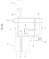
- the coolant injected through a coolant injection port 20 reaches the front end portion of a thermostat housing 50 through the radiator 30.
- a certain temperature e.g. 80°C
- the initial coolant having a low coolant temperature cannot be supplied directly to the water pump 70 through the thermostat housing 50. Therefore, the injected coolant may be supplied to the engine 10 only when it is filled up to the engine coolant outlet 60.
- the coolant that has been supplied to the engine 10 and has passed through a head 11, a head gasket 12, and a block 13 of the engine 10 reaches the water pump 70 and the thermostat housing 50, and some of the coolant supplied to the engine 10 reaches the thermostat housing 50 through the bypass 90. As such, some of the coolant is transferred to an exhaust gas recirculation (EGR) cooler 100 and a heater core 110 for heating the vehicle through the flow path branched from the engine coolant outlet 60.
- EGR exhaust gas recirculation
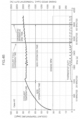
- a coolant injection time becomes excessively long, and as illustrated in FIG. 7 , the coolant temperature does not reach the changing temperature of the thermostat until reaching one hour after the idle operation, such that there can exist the case that the coolant is not sufficiently injected.
- the cooling system may include a water pump 70 for pushing coolant into an engine of the vehicle 10, a radiator 30 for performing a cooling operation by receiving the coolant discharged from the engine 10 and heat-exchanging with the outside air according to the opening of a thermostat, when the temperature of the coolant, which circulates the cooling system, has been heated at a certain temperature or higher by continuously operating the engine 10, a bypass 90 for connecting an engine of the vehicle coolant outlet 60 and an engine of the vehicle coolant inlet 40, and a reservoir tank connected to the radiator 30 and for storing the residual coolant.
- EP 2 923 052 A2 , US 2013/263802 A1 and FR 3 052 185 A1 each disclose a method of charging coolant in a cooling system for a vehicle.
- FIG. 5A An ideal cooling system illustrated in FIG. 5A is as in FIG. 5B .
- the present invention is directed to solve the problems, and an object of the present invention is directed to providing a method for replenishing coolant in a cooling system for a vehicle, which has improved injection convenience and injection reliability at the time of charging coolant.
- the present invention is not limited to the engine coolant circulation system illustrated in FIG. 5A and FIG. 5B , but can also be applied to a coolant circulation system in which some devices are deleted or added.
- a method for charging coolant in a cooling system for a vehicle includes determining a vehicle-diagnostic apparatus connection that determines whether a diagnostic apparatus configured for charging coolant has been connected to a vehicle; starting a coolant charging mode for charging the coolant by the diagnostic apparatus; and determining whether to satisfy a coolant charging mode release condition after starting the coolant charging mode.
- EGR Exhaust Gas Recirculation
- an alarm indicating that the coolant charging mode is in progress may be displayed on an instrument panel in the vehicle.
- the diagnostic apparatus is configured to apply a control signal to an ECU so that an engine of the vehicle is driven by alternately switching between a first operation mode for operating the engine at a predetermined first RPM for a first predetermined time period, and a second operation mode for operating the engine at a second RPM different from the first RPM for a second predetermined time.
- the engine it is possible to operate the engine at a predetermined operation mode, increasing the coolant temperature up to the changing temperature of the thermostat. Furthermore, it is possible to alternately operate the engine at different operation modes from each other, preventing the engine from being overheated.
- the method for charging the coolant in the cooling system for the vehicle may further include determining whether the coolant temperature is equal to or greater than a predetermined first temperature, and when the coolant temperature is equal to or greater than the predetermined first temperature, the coolant charging mode release condition is determined.
- the vehicle may include an electric thermostat for opening and closing the cooling flow path of the cooling system, and in the coolant charging mode, the diagnostic apparatus is configured to apply a control duty value for controlling a heat-generation amount of a heater provided in the electric thermostat, adjusting the opening and closing amount of the electric thermostat.
- the diagnostic apparatus is configured to control so that signals of predetermined different duty magnitudes and applying times from each other are alternately repeated with respect to a PWM duty signal applied to the heater.
- the method for charging the coolant in the cooling system for the vehicle may further include determining whether the coolant temperature is equal to or greater than a predetermined first temperature, and when the coolant temperature is equal to or greater than the predetermined first temperature, the control duty value may be applied to the electric thermostat.
- the present invention drives the heater when the coolant temperature is equal to or greater than the predetermined temperature so that the heater is not driven meaninglessly.
- the vehicle may include an electric thermostat for opening and closing the cooling flow path of the cooling system, and the method for charging the coolant in the cooling system for the vehicle may further include determining whether the coolant temperature is equal to or greater than a predetermined first temperature through a primary engine drive control, and when the coolant temperature is equal to or greater than the predetermined first temperature, the diagnostic apparatus is configured to apply a control duty value for controlling a heat-generation amount of a heater provided in the electric thermostat, adjusting the opening and closing amount of the electric thermostat.
- the heater of the electric thermostat after driving the engine at a predetermined drive mode so that the coolant temperature becomes the predetermined first temperature or higher, smoothly charging the coolant even when the coolant temperature is equal to or lower than the predetermined first temperature.
- the diagnostic apparatus is configured to apply the control duty value to the electric thermostat, and applies the control signal to the ECU so that an engine of the vehicle is driven by alternately switching between a third operation mode for operating the engine at a predetermined third RPM for a third predetermined time period, and a fourth operation mode for operating the engine at a fourth RPM different from the third RPM for a fourth predetermined time.
- the method for charging the coolant in the cooling system for the vehicle may further include determining whether a vehicle charging mode entry condition has been satisfied, when at least any one condition among the conditions in which a transmission of the vehicle is positioned at the park shifting stage (P-stage), an engine of the vehicle is being driven, and a vehicle speed is zero is satisfied.
- a coolant charging mode end portion thereof is selected by use of the diagnostic apparatus, the vehicle charging mode entry condition is not satisfied, and an abnormality has occurred in the electrical portions are satisfied, it is determined that a coolant charging mode release condition has been achieved.
- the present invention is a diagnostic apparatus configured for charging coolant using the method for charging the coolant.
- the diagnostic apparatus unlike the conventional method for charging the coolant that has been dependent on the manual operation of the operator, having no need to input additional manpower after setting the coolant injection equipment and increasing the coolant injection convenience.
- the present invention may be applied not only to a vehicle having a cooling system adopting an electric thermostat but also to a cooling system adopting a mechanical thermostat, and the above-described same operation and effects of the present invention may be exerted even in the cooling system adopting the mechanical thermostat.
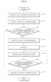
- FIG. 1 is a flowchart illustrating a method for actually injecting coolant into a vehicle by use of a method for charging coolant in a cooling system for a vehicle according to an exemplary embodiment of the present invention.
- a radiator cap is first opened in a started-up state to inject a certain amount of coolant into the vehicle until the coolant does not enter through the coolant injection port 20 S 100.
- the injection amount of coolant may be a different amount according to the vehicle and the injection state.
- the diagnostic apparatus is a diagnostic apparatus configured for the vehicle driven by a Global Diagnostic System (GDS).
- GDS Global Diagnostic System
- the diagnostic apparatus may include a controller which may be at least one microprocessor operated by a predetermined program which may include a series of commands for carrying out a method in accordance with various exemplary embodiments of the present invention.
- the vehicle is started-up S300, and a coolant charging mode is operated by use of the diagnostic apparatus in a state where an engine of the vehicle is in a predetermined operation state (e.g., an idle state) S400.
- a predetermined operation state e.g., an idle state
- the operation of the coolant charging mode may be started by the operator inputting a predetermined instruction to the diagnostic apparatus or pressing a specific button provided in the diagnostic apparatus.
- the coolant charging control which will be described later with reference to FIG. 2 and FIG. 3 , is performed.
- the coolant charging mode is released and the engine is started-off S500.
- the vehicle is left for a predetermined time so that the coolant reduces to a proper water temperature after the engine has been started-off S600.
- FIG. 2 is a flowchart illustrating the method for charging the coolant in the cooling system for the vehicle according to an exemplary embodiment of the present invention in the vehicle having the cooling system adopting a mechanical thermostat.
- the method for charging the coolant according to an exemplary embodiment of the present invention will be described in more detail focusing on a coolant charging mode S400 illustrated in FIG. 1 .
- the diagnostic apparatus is connected to a predetermined interface of the vehicle that has been started-off S 10.
- the operator selects the coolant charging mode by operating a predetermined switch provided in the diagnostic apparatus, or inputting a predetermined instruction into a GDS program through an input device such as a keyboard S11.
- the diagnostic apparatus determines whether a predetermined coolant charging mode entry condition is satisfied S12.
- the coolant charging mode entry condition means a basic condition required to be satisfied to stably perform the coolant injection operation. Even when the coolant charging mode is selected by the operator, the coolant charging mode cannot proceed when the predetermined coolant charging mode entry condition is not satisfied.
- the diagnostic apparatus When it is determined in the S12 that the coolant charging mode entry condition has been satisfied, the diagnostic apparatus enters the coolant charging mode S13.
- the diagnostic apparatus preferably transmits a control signal to a controller such as engine control unit (ECU) so that the EGR function is turned off S14.
- ECU engine control unit
- the diagnosis unit takes out the air in the cooling system, and performs a control of increasing the coolant temperature up to the changing temperature of a thermostat so that the proper amount of coolant may be supplied to the entire cooling system.
- the diagnostic apparatus is configured to control the ECU so that the engine 10 may be operated at a predetermined RPM.
- the engine damage due to overheating of the engine 10 can occur, such that after rotating the engine 10 at a high speed for a first predetermined time period, it is preferable to rotate the engine 10 at a low speed for a second predetermined time.
- a control signal is applied to the ECU so that the engine is driven by alternately switching between an operation mode for driving the engine at the idle RPM for 60 seconds and an operation mode for driving the engine at the RPM of 2000rpm for 60 seconds.
- the exemplary RPM and operation time of the engine can vary according to the vehicle model.
- the diagnostic apparatus determines whether the coolant charging mode release condition has been satisfied to determine whether the coolant has been sufficiently supplied by performing the coolant charging mode in the S 15 or whether the coolant charging mode may be stopped by the external condition S 16.
- the coolant charging mode release condition has been achieved when at least any one condition among the conditions in which the coolant temperature is equal to or greater than a predetermined second temperature, a coolant charging mode end portion thereof is selected by use of the diagnostic apparatus, the vehicle charging mode entry condition in the S 12 is not satisfied, and an abnormality has occurred in the electrical parts.
- the second temperature means a temperature capable of changing the mechanical thermostat for opening and closing the flow path of the cooling system.
- the second temperature is preferably 85 °C, but the corresponding temperature range can vary according to the characteristics of the thermostat provided in the vehicle.
- the coolant charging mode is released when the operator inputs the coolant charging mode end instruction S 17. Furthermore, when the coolant charging mode entry condition determined in the S 12 is not satisfied, or when it is determined that an abnormality has occurred in the in-vehicle electrical portions such as a coolant temperature sensor, it is difficult to stably supply the coolant, such that even in the instant case, the coolant charging mode is released S 17. As such, when the coolant is sufficiently supplied and the coolant charging mode is released, the EGR function stopped in the S 14 may be resumed.
- FIG. 3 is a flowchart illustrating the method for charging the coolant in the cooling system for the vehicle according to an exemplary embodiment of the present invention in the vehicle having a cooling system adopting an electric thermostat.
- a heater is provided therein, such that the change in the thermostat is possible by driving the heater even when the coolant temperature does not reach a predetermined temperature.
- FIG. 3 focusing on the coolant charging mode S400 in the vehicle having the cooling system adopting the electric thermostat.
- S21 to S25 illustrated in the flowchart of FIG. 3 are substantially the same as the S10 to S 14 illustrated in FIG. 2 . Therefore, duplicate description of the contents described with reference to FIG. 2 will be omitted.
- a PWM control for driving the heater provided in the electric thermostat may be performed instead of a control of driving the engine at a predetermined RPM S28.
- the diagnostic apparatus transfers a control signal for driving the heater provided in the electric thermostat to the ECU, and the ECU controls the heater of the electric thermostat according to the instruction of the diagnostic apparatus.
- the heater may be overheated and damaged, such that it is preferable to control the heater so that signals of predetermined different duty magnitudes and duty applying times from each other are alternately repeated.
- the diagnostic apparatus instructs a control so that a control of applying a control duty value of output 100% for 40 seconds and a control of applying a control duty value of output 40% for 20 seconds are alternately performed.
- a control of applying a control duty value of output 100% for 40 seconds and a control of applying a control duty value of output 40% for 20 seconds are alternately performed.
- the diagnostic apparatus determines whether the coolant temperature is equal to or greater than a predetermined first temperature (e.g., 75 °C) S27, and performs a control of the electric thermostat in S28 only when the coolant temperature is equal to or greater than the predetermined first temperature.
- a predetermined first temperature e.g. 75 °C
- a primary engine drive control for operating the engine in a predetermined operation mode S26 is performed so that the coolant temperature is equal to or greater than the predetermined first temperature.
- the diagnostic apparatus instructs the ECU to alternately perform different engine drive modes.
- the engine may be driven by alternately switching between an operation mode for driving the engine at the idle RPM for 60 seconds and an operation mode for driving the engine at the RPM of 2000rpm for 60 seconds.
- the control of the electric thermostat in the S28 is performed as described above.
- the coolant charging mode release condition As such, as in the S16 of an exemplary embodiment in FIG. 2 , after the start of the coolant charging mode, it is determined whether the predetermined coolant charging mode release condition has been satisfied S30, and when the corresponding condition has been satisfied, the coolant charging mode is released. When it reaches the second temperature (e.g., 80 °C) configured for changing the electric thermostat, the electric thermostat is changed, and therefore, the conditions for taking out the coolant in the cooling system and supplying the proper amount of coolant are satisfied, releasing the coolant charging mode S31.
- the second temperature e.g. 80 °C
- the coolant charging mode is released when the coolant charging mode end portion instruction is inputted by the operator S31. Furthermore, when the coolant charging mode entry condition determined in the S23 is not satisfied, or it is determined that an abnormality has occurred in the in-vehicle electric components such as the coolant temperature sensor and the heater of the electric thermostat, it is difficult to stably supply the coolant, such that even in the instant case, the coolant charging mode is released S31. As such, when the coolant is sufficiently supplied and the coolant charging mode is released, the EGR function stopped in the S25 may be resumed.
- a control is performed to drive the heater of the electric thermostat in the coolant charging mode.
- a control for driving the heater of the electric thermostat and operating the engine in a predetermined operation mode (hereinafter referred to as 'secondary engine drive control' ) can also be performed in parallel to increase the coolant temperature up to the changing temperature of the electric thermostat more rapidly.
- the diagnostic apparatus instructs the ECU to alternately perform between the different engine drive modes.
- the engine can also be driven by alternately switching between an operation mode for driving the engine at the idle RPM for 60 seconds and an operation mode for driving the engine at the RPM of 2000rpm for 40 seconds.
- the operation conditions of the engine in the primary engine drive control and the secondary engine drive control may be the same, or can also be performed in different conditions from each other.
- the heater control and the secondary engine drive control of the electric thermostat when the coolant temperature reaches a predetermined temperature configured for changing the electric thermostat, the coolant charging mode is released S31 as described above.
- FIG. 4A , FIG. 4B and FIG. 4C by comparing the cooling charging times of according to an exemplary embodiment of the present invention and a comparative example.
- the coolant of the radiator and the thermostat of the vehicle having the cooling system adopting the electric thermostat were all discharged, and the discharged coolant at the present time was measured (3800ml in the present example).
- the radiator cap of the vehicle was opened in the started-off state and the discharged coolant was primarily injected therein again, and the amount of coolant remaining after injection was measured (480ml in the present example).
- the coolant was charged by varying the charging conditions in the coolant charging mode, and the time until the amount of coolant remaining after the primary injection was all charged was measured.
- the diagnostic apparatus controlled so that the heater of the electric thermostat was driven when the coolant temperature reached 75 °C, and when the coolant temperature reached 85 °C, the coolant charging mode was released.
- the charging required time for each coolant charging condition was as in Table 1 as follows.
- Table 1 Items Coolant temperature (°C) Charging consumption time Total required time (minute) Remark Heater On Heater Off Primary charging (1) Before operating a heater (2) After operating a heater (3) (1)+(2)+(3) Case #1 - - 20 minutes 90 minutes - 110 minutes Comparative example Case #2 75 °C 80 °C 20 minutes 21 minutes 38.5 minutes 79.5 minutes Present invention example Case #3 75 °C 80 °C 20 minutes 14 minutes 14.1 minutes 48.1 minutes Present invention example
- the RPM of the engine was alternately switched between the idle and 2000rpm, such that the time required for the coolant temperature to increase to 75 °C was shortened by 7 minutes as compared with the Case #2, and furthermore, the time to reach the coolant temperature (80 °C) at which the electric thermostat was changed was further shortened as compared with the Case #2.
- the total required time for charging the coolant was 48.1 minutes, which could be shortened as compared with the Case #1 and the Case #2.
Landscapes
- Engineering & Computer Science (AREA)
- Chemical & Material Sciences (AREA)
- Combustion & Propulsion (AREA)
- Mechanical Engineering (AREA)
- General Engineering & Computer Science (AREA)
- Combined Controls Of Internal Combustion Engines (AREA)
- Electric Propulsion And Braking For Vehicles (AREA)
Claims (12)
- Verfahren zum Zuführen von Kühlmittel in einem Kühlsystem für ein Fahrzeug, wobei das Verfahren aufweist:Ermitteln, wenn eine Diagnosevorrichtung, die zum Zuführen des Kühlmittels konfiguriert ist, mit einem Fahrzeug verbunden wurde (S200);Starten eines Verbrennungsmotors (10) des Fahrzeuges in einem vorbestimmten Betriebszustand (S300);in einer Erwiderung, dass ermittelt wird, dass die Diagnosevorrichtung, die zum Zuführen des Kühlmittels konfiguriert ist, mit dem Fahrzeug verbunden ist, Starten eines Kühlmittelzuführmodus zum Zuführen des Kühlmittels durch die Diagnosevorrichtung nach dem Starten des Verbrennungsmotors (10) (S400); undErmitteln durch die Diagnosevorrichtung, wenn eine Kühlmittelzuführmodus-Aufhebebedingung erfüllt wurde, nach dem Starten des Kühlmittelzuführmodus (S500),wobei in einer Erwiderung, dass ermittelt wird, dass der Kühlmittelzuführmodus eingetreten ist, ein Antrieb einer Abgasrückführung(EGR)-Vorrichtung abgeschaltet wird (S14; S25).
- Verfahren zum Zuführen des Kühlmittels in dem Kühlsystem für das Fahrzeug nach Anspruch 1,
wobei in der Erwiderung, dass ermittelt wird, dass der Kühlmittelzuführmodus eingetreten ist, ein Alarm, der angibt, dass der Kühlmittelzuführmodus im Gange ist, an einer Instrumententafel in dem Fahrzeug angezeigt wird. - Verfahren zum Zuführen des Kühlmittels in dem Kühlsystem für das Fahrzeug nach Anspruch 1 oder 2,
wobei in dem Kühlmittelzuführmodus die Diagnosevorrichtung konfiguriert ist, ein Steuersignal an eine Verbrennungsmotorsteuereinheit (ECU) abzugeben, so dass der Verbrennungsmotor (10) des Fahrzeuges durch abwechselndes Schalten zwischen einem ersten Betriebsmodus zum Betreiben des Verbrennungsmotors (10) mit einer vorbestimmten ersten Drehzahl (U/min) für einen ersten vorbestimmten Zeitraum und einem zweiten Betriebsmodus zum Betreiben des Verbrennungsmotors (10) mit einer von der ersten Drehzahl verschiedenen zweiten Drehzahl für einen zweiten vorbestimmten Zeitraum angetrieben wird. - Verfahren zum Zuführen des Kühlmittels in dem Kühlsystem für das Fahrzeug nach irgendeinem der Ansprüche 1 bis 3, ferner aufweisend:Ermitteln, wenn eine Kühlmitteltemperatur gleich wie oder größer als eine vorbestimmte erste Temperatur ist (S27),wobei in einer Erwiderung, dass die Kühlmitteltemperatur gleich wie oder größer als die vorbestimmte erste Temperatur ist, die Kühlmittelzuführmodus-Aufhebebedingung ermittelt wird (S31).
- Verfahren zum Zuführen des Kühlmittels in dem Kühlsystem für das Fahrzeug nach irgendeinem der Ansprüche 1 bis 4,wobei das Fahrzeug einen elektrischen Thermostat zum Öffnen und Schließen eines Kühlungsströmungspfades des Kühlsystems aufweist, undwobei in dem Kühlmittelzuführmodus die Diagnosevorrichtung konfiguriert ist, einen Steuertaktwert zur Steuerung einer Wärmeerzeugungsmenge einer in dem elektrischen Thermostat vorgesehenen Heizung abzugeben, der einen Öffnungs- und Schließbetrag des elektrischen Thermostats einstellt.
- Verfahren zum Zuführen des Kühlmittels in dem Kühlsystem für das Fahrzeug nach Anspruch 5,
wobei in dem Kühlmittelzuführmodus die Diagnosevorrichtung konfiguriert ist, derart zu steuern, dass Signale von vorbestimmten voneinander verschiedenen Taktgrößen und Aufbringzeiten in Bezug auf ein an die Heizung abgegebenes Pulsweitenmodulation(PWM)-Taktsignal abwechselnd wiederholt werden. - Verfahren zum Zuführen des Kühlmittels in dem Kühlsystem für das Fahrzeug nach Anspruch 5 oder 6, ferner aufweisendErmitteln, wenn eine Kühlmitteltemperatur gleich wie oder größer als eine vorbestimmte erste Temperatur ist (S27),wobei in einer Erwiderung, dass die Kühlmitteltemperatur gleich wie oder größer als die vorbestimmte erste Temperatur ist, der Steuertaktwert auf den elektrischen Thermostaten aufgebracht wird (S28).
- Verfahren zum Zuführen des Kühlmittels in dem Kühlsystem für das Fahrzeug nach den Ansprüchen 1 bis 3, ferner aufweisend:Ermitteln, wenn eine Kühlmitteltemperatur gleich wie oder größer als eine vorbestimmte erste Temperatur ist, undwobei in einer Erwiderung, dass die Kühlmitteltemperatur gleich wie oder größer als die vorbestimmte erste Temperatur ist, die Diagnosevorrichtung konfiguriert ist, einen Steuertaktwert zur Steuerung einer Wärmeerzeugungsmenge einer in einem elektrischen Thermostat zum Öffnen und Schließen eines Kühlungsströmungspfades des Kühlsystems vorgesehenen Heizung abzugeben, der einen Öffnungs- und Schließbetrag des elektrischen Thermostats einstellt.
- Verfahren zum Zuführen des Kühlmittels in dem Kühlsystem für das Fahrzeug nach Anspruch 8,
wobei in dem Kühlmittelzuführmodus die Diagnosevorrichtung konfiguriert ist, den Steuertaktwert an den elektrischen Thermostaten abzugeben und das Steuersignal auf die ECU aufzubringen, so dass der Verbrennungsmotor (10) durch abwechselndes Schalten zwischen einem dritten Betriebsmodus zum Betreiben des Verbrennungsmotors (10) mit einer vorbestimmten dritten Drehzahl für einen dritten vorbestimmten Zeitraum und einem vierten Betriebsmodus zum Betreiben des Verbrennungsmotors (10) mit einer von der dritten Drehzahl verschiedenen vierten Drehzahl für einen vierten vorbestimmten Zeitraum angetrieben wird. - Verfahren zum Zuführen des Kühlmittels in dem Kühlsystem für das Fahrzeug nach irgendeinem der Ansprüche 1 bis 9, ferner aufweisend:Ermitteln, wenn eine Fahrzeugzuführmodus-Eintrittsbedingung erfüllt ist,wobei, wenn wenigstens eine Bedingung unter einer Mehrzahl von Bedingungen, bei welchen ein Getriebe des Fahrzeuges in einer Parkschaltstufe (P-Stufe) positioniert ist, der Verbrennungsmotor (10) des Fahrzeuges angetrieben wird und eine Fahrzeuggeschwindigkeit Null ist, erfüllt ist, ermittelt wird, dass die Fahrzeugzuführmodus-Eintrittsbedingung erfüllt wurde.
- Verfahren zum Zuführen des Kühlmittels in dem Kühlsystem für das Fahrzeug nach Anspruch 1,
wobei in einer Erwiderung, dass wenigstens eine Bedingung unter einer Mehrzahl von Bedingungen, bei welchen eine Kühlmitteltemperatur gleich wie oder größer als eine zweite Temperatur ist, ein Kühlmittelzuführmodus-Endabschnitt davon durch Verwendung der Diagnosevorrichtung ausgewählt ist, eine Fahrzeugzuführmodus-Eintrittsbedingung nicht erfüllt ist und eine Abnormalität in elektrischen Abschnitten aufgetreten ist, erfüllt ist, ermittelt wird, dass eine Kühlmittelzuführmodus-Aufhebebedingung erlangt wurde. - Diagnosevorrichtung zum Zuführen des Kühlmittels unter Verwendung eines Verfahrens zum Zuführen des Kühlmittels nach irgendeinem der Ansprüche 1 bis 11.
Applications Claiming Priority (1)
| Application Number | Priority Date | Filing Date | Title |
|---|---|---|---|
| KR1020190025742A KR102714868B1 (ko) | 2019-03-06 | 2019-03-06 | 자동차용 냉각 시스템의 냉각수 충진 방법 |
Publications (2)
| Publication Number | Publication Date |
|---|---|
| EP3705694A1 EP3705694A1 (de) | 2020-09-09 |
| EP3705694B1 true EP3705694B1 (de) | 2023-06-28 |
Family
ID=68501420
Family Applications (1)
| Application Number | Title | Priority Date | Filing Date |
|---|---|---|---|
| EP19207978.8A Active EP3705694B1 (de) | 2019-03-06 | 2019-11-08 | Verfahren zum einfüllen von kühlmittel in das kühlsystem eines fahrzeugs |
Country Status (5)
| Country | Link |
|---|---|
| US (1) | US10760473B1 (de) |
| EP (1) | EP3705694B1 (de) |
| JP (1) | JP2020143666A (de) |
| KR (1) | KR102714868B1 (de) |
| CN (1) | CN111663993B (de) |
Families Citing this family (6)
| Publication number | Priority date | Publication date | Assignee | Title |
|---|---|---|---|---|
| CN112228209A (zh) * | 2020-09-07 | 2021-01-15 | 联合汽车电子有限公司 | 一种冷却液加注方法、加注装置及可读存储介质 |
| CN114911210B (zh) * | 2021-02-08 | 2025-07-11 | 广汽埃安新能源汽车股份有限公司 | 冷却液加注方法、液冷温控系统和诊断设备 |
| CN116181475B (zh) * | 2021-11-26 | 2025-04-01 | 广州汽车集团股份有限公司 | 一种冷却液加注排空控制方法 |
| CN115030807B (zh) * | 2022-03-21 | 2024-06-04 | 中国第一汽车股份有限公司 | 一种冷却液加注控制方法及装置 |
| CN115288838B (zh) * | 2022-06-13 | 2023-09-19 | 中国第一汽车股份有限公司 | 一种加注冷却液时的中冷循环水泵控制方法及存储介质 |
| CN115419499B (zh) * | 2022-09-01 | 2024-01-09 | 浙江吉利控股集团有限公司 | 车辆冷却回路排气加注方法、装置、设备及存储介质 |
Family Cites Families (25)
| Publication number | Priority date | Publication date | Assignee | Title |
|---|---|---|---|---|
| US3188006A (en) * | 1963-10-09 | 1965-06-08 | Union Carbide Corp | Apparatus for cleaning and filling engine cooling systems |
| US3180759A (en) * | 1964-05-21 | 1965-04-27 | Union Carbide Corp | Automotive cooling system flushing method |
| US3576181A (en) * | 1969-06-02 | 1971-04-27 | Cummins Engine Co Inc | Apparatus for deaerating an engine cooling system |
| DE3226508C2 (de) * | 1982-07-15 | 1985-12-12 | Bayerische Motoren Werke AG, 8000 München | Kühlkreis für Brennkraftmaschinen |
| US4790882A (en) * | 1985-03-14 | 1988-12-13 | Autospa Corporation | Flushing and recharging method for the cooling system of an automotive engine |
| US4911211A (en) * | 1988-11-01 | 1990-03-27 | Andersen Robert A | Apparatus and method for changing coolant in vehicle cooling system |
| DE4422272A1 (de) * | 1994-06-24 | 1996-01-04 | Bayerische Motoren Werke Ag | Kühlvorrichtung für einen flüssigkeitsgekühlten Verbrennungsmotor eines Kraftfahrzeuges |
| US6159276A (en) * | 1999-01-08 | 2000-12-12 | Scix, Llc | Sealing system for combustible engines and the like |
| US6647622B2 (en) * | 2000-01-03 | 2003-11-18 | Scix, Llc | Repairing an engine cooling system |
| KR100405537B1 (ko) | 2001-04-09 | 2003-11-14 | 현대자동차주식회사 | 자동차용 냉각시스템의 공기제거 및 냉각수 보충장치 |
| US7111651B2 (en) * | 2004-08-25 | 2006-09-26 | Robert A. Doty | Engine coolant changing system |
| JP4613121B2 (ja) * | 2005-11-18 | 2011-01-12 | 本田技研工業株式会社 | 内燃機関の吸気量検出装置 |
| FR2921432A1 (fr) * | 2007-09-21 | 2009-03-27 | Renault Sas | Procede de diagnostic d'une defaillance d'un organe du dispositif egr d'un moteur a combustion interne |
| JP4968095B2 (ja) | 2008-02-07 | 2012-07-04 | 日産自動車株式会社 | エンジンの冷却装置及びエンジンの冷却装置におけるエア抜き方法 |
| US8813792B2 (en) | 2011-06-17 | 2014-08-26 | International Truck Intellectual Property Company, Llc | Tool and method for draining and refilling a cooling system |
| KR101875620B1 (ko) * | 2012-04-10 | 2018-07-06 | 현대자동차 주식회사 | 엔진 냉각 시스템과 전자식 서모스탯 제어장치 및 방법 |
| JP2014001681A (ja) * | 2012-06-18 | 2014-01-09 | Toyota Motor Corp | 冷却システムの異常診断装置 |
| JP5641037B2 (ja) * | 2012-11-20 | 2014-12-17 | トヨタ自動車株式会社 | 冷却装置 |
| JP6120649B2 (ja) | 2013-04-05 | 2017-04-26 | 日野自動車株式会社 | Egr装置 |
| US9803545B1 (en) * | 2013-07-25 | 2017-10-31 | David Coleman Whitmer | Engine coolant forward flushing apparatus and method |
| FR3052185B1 (fr) | 2016-06-07 | 2018-06-15 | Peugeot Citroen Automobiles Sa | Procede de remplissage en fluide caloporteur d’un circuit de refroidissement |
| JP6738237B2 (ja) * | 2016-08-12 | 2020-08-12 | 株式会社Subaru | 冷却装置 |
| JP6335236B2 (ja) * | 2016-09-09 | 2018-05-30 | 株式会社Subaru | 車両用冷却装置 |
| JP6491632B2 (ja) * | 2016-11-09 | 2019-03-27 | 株式会社Subaru | 車両用冷却装置 |
| US10012133B1 (en) * | 2017-02-13 | 2018-07-03 | Ford Global Technologies, Llc | Method and system for maintaining an engine coolant level |
-
2019
- 2019-03-06 KR KR1020190025742A patent/KR102714868B1/ko active Active
- 2019-11-04 US US16/673,847 patent/US10760473B1/en active Active
- 2019-11-08 EP EP19207978.8A patent/EP3705694B1/de active Active
- 2019-11-13 JP JP2019205600A patent/JP2020143666A/ja active Pending
- 2019-11-22 CN CN201911154970.6A patent/CN111663993B/zh not_active Expired - Fee Related
Also Published As
| Publication number | Publication date |
|---|---|
| JP2020143666A (ja) | 2020-09-10 |
| US20200284185A1 (en) | 2020-09-10 |
| KR20200107127A (ko) | 2020-09-16 |
| KR102714868B1 (ko) | 2024-10-08 |
| CN111663993B (zh) | 2023-09-29 |
| US10760473B1 (en) | 2020-09-01 |
| EP3705694A1 (de) | 2020-09-09 |
| CN111663993A (zh) | 2020-09-15 |
Similar Documents
| Publication | Publication Date | Title |
|---|---|---|
| EP3705694A1 (de) | Verfahren zum einfüllen von kühlmittel in das kühlsystem eines fahrzeugs | |
| JP4103663B2 (ja) | エンジンの冷却装置 | |
| US8439003B2 (en) | Cooling apparatus for internal combustion engine, method of controlling the same, and hybrid vehicle including the same | |
| US6520136B2 (en) | Warm-up control device for internal-combustion engine and warm-up control method | |
| CN116181475B (zh) | 一种冷却液加注排空控制方法 | |
| WO2006005930A2 (en) | Operating internal combustion engines with plant oil | |
| EP4438367B1 (de) | Verfahren und vorrichtung zur kühlung des motorantriebsstillstands für fahrzeug und fahrzeug | |
| JP2004360509A (ja) | 内燃機関の冷却装置 | |
| CN112228209A (zh) | 一种冷却液加注方法、加注装置及可读存储介质 | |
| CN101228350A (zh) | 附属动力单元的自动启动 | |
| JP4968095B2 (ja) | エンジンの冷却装置及びエンジンの冷却装置におけるエア抜き方法 | |
| JP2013035504A (ja) | ハイブリッド車両の冷却装置 | |
| JP2002021560A (ja) | 蓄熱装置を有する内燃機関 | |
| JP3906748B2 (ja) | 内燃機関の冷却装置 | |
| JP4100220B2 (ja) | エンジンの冷却装置 | |
| JP3906745B2 (ja) | 内燃機関の冷却装置 | |
| JP3812530B2 (ja) | 車載器機の昇温装置 | |
| JP4238543B2 (ja) | 蓄熱装置を備えた内燃機関 | |
| JPH07305628A (ja) | 原動機付車両の液体によって冷却される内燃機関のための冷却装置 | |
| JP6358025B2 (ja) | 電動ウォータポンプ装置 | |
| US20240300383A1 (en) | Thermal management system | |
| JP7043143B2 (ja) | 内燃機関の冷却水制御装置 | |
| KR20080032729A (ko) | 하이브리드 차량의 냉각제어장치 및 제어방법 | |
| JP2002138833A (ja) | 蓄熱装置を備えた内燃機関 | |
| JP2002188443A (ja) | 内燃機関の冷却装置 |
Legal Events
| Date | Code | Title | Description |
|---|---|---|---|
| PUAI | Public reference made under article 153(3) epc to a published international application that has entered the european phase |
Free format text: ORIGINAL CODE: 0009012 |
|
| STAA | Information on the status of an ep patent application or granted ep patent |
Free format text: STATUS: REQUEST FOR EXAMINATION WAS MADE |
|
| 17P | Request for examination filed |
Effective date: 20200625 |
|
| AK | Designated contracting states |
Kind code of ref document: A1 Designated state(s): AL AT BE BG CH CY CZ DE DK EE ES FI FR GB GR HR HU IE IS IT LI LT LU LV MC MK MT NL NO PL PT RO RS SE SI SK SM TR |
|
| AX | Request for extension of the european patent |
Extension state: BA ME |
|
| STAA | Information on the status of an ep patent application or granted ep patent |
Free format text: STATUS: EXAMINATION IS IN PROGRESS |
|
| 17Q | First examination report despatched |
Effective date: 20210519 |
|
| RAP3 | Party data changed (applicant data changed or rights of an application transferred) |
Owner name: HYUNDAI MOTOR COMPANY Owner name: KIA CORPORATION |
|
| GRAP | Despatch of communication of intention to grant a patent |
Free format text: ORIGINAL CODE: EPIDOSNIGR1 |
|
| STAA | Information on the status of an ep patent application or granted ep patent |
Free format text: STATUS: GRANT OF PATENT IS INTENDED |
|
| INTG | Intention to grant announced |
Effective date: 20230207 |
|
| GRAS | Grant fee paid |
Free format text: ORIGINAL CODE: EPIDOSNIGR3 |
|
| GRAA | (expected) grant |
Free format text: ORIGINAL CODE: 0009210 |
|
| STAA | Information on the status of an ep patent application or granted ep patent |
Free format text: STATUS: THE PATENT HAS BEEN GRANTED |
|
| AK | Designated contracting states |
Kind code of ref document: B1 Designated state(s): AL AT BE BG CH CY CZ DE DK EE ES FI FR GB GR HR HU IE IS IT LI LT LU LV MC MK MT NL NO PL PT RO RS SE SI SK SM TR |
|
| REG | Reference to a national code |
Ref country code: CH Ref legal event code: EP |
|
| P01 | Opt-out of the competence of the unified patent court (upc) registered |
Effective date: 20230530 |
|
| REG | Reference to a national code |
Ref country code: AT Ref legal event code: REF Ref document number: 1582864 Country of ref document: AT Kind code of ref document: T Effective date: 20230715 |
|
| REG | Reference to a national code |
Ref country code: IE Ref legal event code: FG4D |
|
| REG | Reference to a national code |
Ref country code: DE Ref legal event code: R096 Ref document number: 602019031627 Country of ref document: DE |
|
| REG | Reference to a national code |
Ref country code: LT Ref legal event code: MG9D |
|
| PG25 | Lapsed in a contracting state [announced via postgrant information from national office to epo] |
Ref country code: SE Free format text: LAPSE BECAUSE OF FAILURE TO SUBMIT A TRANSLATION OF THE DESCRIPTION OR TO PAY THE FEE WITHIN THE PRESCRIBED TIME-LIMIT Effective date: 20230628 Ref country code: NO Free format text: LAPSE BECAUSE OF FAILURE TO SUBMIT A TRANSLATION OF THE DESCRIPTION OR TO PAY THE FEE WITHIN THE PRESCRIBED TIME-LIMIT Effective date: 20230928 |
|
| REG | Reference to a national code |
Ref country code: NL Ref legal event code: MP Effective date: 20230628 |
|
| REG | Reference to a national code |
Ref country code: AT Ref legal event code: MK05 Ref document number: 1582864 Country of ref document: AT Kind code of ref document: T Effective date: 20230628 |
|
| PG25 | Lapsed in a contracting state [announced via postgrant information from national office to epo] |
Ref country code: RS Free format text: LAPSE BECAUSE OF FAILURE TO SUBMIT A TRANSLATION OF THE DESCRIPTION OR TO PAY THE FEE WITHIN THE PRESCRIBED TIME-LIMIT Effective date: 20230628 Ref country code: NL Free format text: LAPSE BECAUSE OF FAILURE TO SUBMIT A TRANSLATION OF THE DESCRIPTION OR TO PAY THE FEE WITHIN THE PRESCRIBED TIME-LIMIT Effective date: 20230628 Ref country code: LV Free format text: LAPSE BECAUSE OF FAILURE TO SUBMIT A TRANSLATION OF THE DESCRIPTION OR TO PAY THE FEE WITHIN THE PRESCRIBED TIME-LIMIT Effective date: 20230628 Ref country code: LT Free format text: LAPSE BECAUSE OF FAILURE TO SUBMIT A TRANSLATION OF THE DESCRIPTION OR TO PAY THE FEE WITHIN THE PRESCRIBED TIME-LIMIT Effective date: 20230628 Ref country code: HR Free format text: LAPSE BECAUSE OF FAILURE TO SUBMIT A TRANSLATION OF THE DESCRIPTION OR TO PAY THE FEE WITHIN THE PRESCRIBED TIME-LIMIT Effective date: 20230628 Ref country code: GR Free format text: LAPSE BECAUSE OF FAILURE TO SUBMIT A TRANSLATION OF THE DESCRIPTION OR TO PAY THE FEE WITHIN THE PRESCRIBED TIME-LIMIT Effective date: 20230929 |
|
| PG25 | Lapsed in a contracting state [announced via postgrant information from national office to epo] |
Ref country code: FI Free format text: LAPSE BECAUSE OF FAILURE TO SUBMIT A TRANSLATION OF THE DESCRIPTION OR TO PAY THE FEE WITHIN THE PRESCRIBED TIME-LIMIT Effective date: 20230628 |
|
| PG25 | Lapsed in a contracting state [announced via postgrant information from national office to epo] |
Ref country code: SK Free format text: LAPSE BECAUSE OF FAILURE TO SUBMIT A TRANSLATION OF THE DESCRIPTION OR TO PAY THE FEE WITHIN THE PRESCRIBED TIME-LIMIT Effective date: 20230628 |
|
| PGFP | Annual fee paid to national office [announced via postgrant information from national office to epo] |
Ref country code: GB Payment date: 20231023 Year of fee payment: 5 |
|
| PG25 | Lapsed in a contracting state [announced via postgrant information from national office to epo] |
Ref country code: ES Free format text: LAPSE BECAUSE OF FAILURE TO SUBMIT A TRANSLATION OF THE DESCRIPTION OR TO PAY THE FEE WITHIN THE PRESCRIBED TIME-LIMIT Effective date: 20230628 |
|
| PG25 | Lapsed in a contracting state [announced via postgrant information from national office to epo] |
Ref country code: IS Free format text: LAPSE BECAUSE OF FAILURE TO SUBMIT A TRANSLATION OF THE DESCRIPTION OR TO PAY THE FEE WITHIN THE PRESCRIBED TIME-LIMIT Effective date: 20231028 |
|
| PG25 | Lapsed in a contracting state [announced via postgrant information from national office to epo] |
Ref country code: SM Free format text: LAPSE BECAUSE OF FAILURE TO SUBMIT A TRANSLATION OF THE DESCRIPTION OR TO PAY THE FEE WITHIN THE PRESCRIBED TIME-LIMIT Effective date: 20230628 Ref country code: SK Free format text: LAPSE BECAUSE OF FAILURE TO SUBMIT A TRANSLATION OF THE DESCRIPTION OR TO PAY THE FEE WITHIN THE PRESCRIBED TIME-LIMIT Effective date: 20230628 Ref country code: RO Free format text: LAPSE BECAUSE OF FAILURE TO SUBMIT A TRANSLATION OF THE DESCRIPTION OR TO PAY THE FEE WITHIN THE PRESCRIBED TIME-LIMIT Effective date: 20230628 Ref country code: PT Free format text: LAPSE BECAUSE OF FAILURE TO SUBMIT A TRANSLATION OF THE DESCRIPTION OR TO PAY THE FEE WITHIN THE PRESCRIBED TIME-LIMIT Effective date: 20231030 Ref country code: IS Free format text: LAPSE BECAUSE OF FAILURE TO SUBMIT A TRANSLATION OF THE DESCRIPTION OR TO PAY THE FEE WITHIN THE PRESCRIBED TIME-LIMIT Effective date: 20231028 Ref country code: ES Free format text: LAPSE BECAUSE OF FAILURE TO SUBMIT A TRANSLATION OF THE DESCRIPTION OR TO PAY THE FEE WITHIN THE PRESCRIBED TIME-LIMIT Effective date: 20230628 Ref country code: EE Free format text: LAPSE BECAUSE OF FAILURE TO SUBMIT A TRANSLATION OF THE DESCRIPTION OR TO PAY THE FEE WITHIN THE PRESCRIBED TIME-LIMIT Effective date: 20230628 Ref country code: CZ Free format text: LAPSE BECAUSE OF FAILURE TO SUBMIT A TRANSLATION OF THE DESCRIPTION OR TO PAY THE FEE WITHIN THE PRESCRIBED TIME-LIMIT Effective date: 20230628 Ref country code: AT Free format text: LAPSE BECAUSE OF FAILURE TO SUBMIT A TRANSLATION OF THE DESCRIPTION OR TO PAY THE FEE WITHIN THE PRESCRIBED TIME-LIMIT Effective date: 20230628 |
|
| PGFP | Annual fee paid to national office [announced via postgrant information from national office to epo] |
Ref country code: FR Payment date: 20231024 Year of fee payment: 5 Ref country code: DE Payment date: 20231023 Year of fee payment: 5 |
|
| PG25 | Lapsed in a contracting state [announced via postgrant information from national office to epo] |
Ref country code: PL Free format text: LAPSE BECAUSE OF FAILURE TO SUBMIT A TRANSLATION OF THE DESCRIPTION OR TO PAY THE FEE WITHIN THE PRESCRIBED TIME-LIMIT Effective date: 20230628 |
|
| REG | Reference to a national code |
Ref country code: DE Ref legal event code: R097 Ref document number: 602019031627 Country of ref document: DE |
|
| PG25 | Lapsed in a contracting state [announced via postgrant information from national office to epo] |
Ref country code: DK Free format text: LAPSE BECAUSE OF FAILURE TO SUBMIT A TRANSLATION OF THE DESCRIPTION OR TO PAY THE FEE WITHIN THE PRESCRIBED TIME-LIMIT Effective date: 20230628 |
|
| PLBE | No opposition filed within time limit |
Free format text: ORIGINAL CODE: 0009261 |
|
| STAA | Information on the status of an ep patent application or granted ep patent |
Free format text: STATUS: NO OPPOSITION FILED WITHIN TIME LIMIT |
|
| PG25 | Lapsed in a contracting state [announced via postgrant information from national office to epo] |
Ref country code: IT Free format text: LAPSE BECAUSE OF FAILURE TO SUBMIT A TRANSLATION OF THE DESCRIPTION OR TO PAY THE FEE WITHIN THE PRESCRIBED TIME-LIMIT Effective date: 20230628 |
|
| 26N | No opposition filed |
Effective date: 20240402 |
|
| REG | Reference to a national code |
Ref country code: CH Ref legal event code: PL |
|
| PG25 | Lapsed in a contracting state [announced via postgrant information from national office to epo] |
Ref country code: MC Free format text: LAPSE BECAUSE OF FAILURE TO SUBMIT A TRANSLATION OF THE DESCRIPTION OR TO PAY THE FEE WITHIN THE PRESCRIBED TIME-LIMIT Effective date: 20230628 |
|
| PG25 | Lapsed in a contracting state [announced via postgrant information from national office to epo] |
Ref country code: LU Free format text: LAPSE BECAUSE OF NON-PAYMENT OF DUE FEES Effective date: 20231108 |
|
| PG25 | Lapsed in a contracting state [announced via postgrant information from national office to epo] |
Ref country code: CH Free format text: LAPSE BECAUSE OF NON-PAYMENT OF DUE FEES Effective date: 20231130 |
|
| PG25 | Lapsed in a contracting state [announced via postgrant information from national office to epo] |
Ref country code: MC Free format text: LAPSE BECAUSE OF FAILURE TO SUBMIT A TRANSLATION OF THE DESCRIPTION OR TO PAY THE FEE WITHIN THE PRESCRIBED TIME-LIMIT Effective date: 20230628 Ref country code: LU Free format text: LAPSE BECAUSE OF NON-PAYMENT OF DUE FEES Effective date: 20231108 Ref country code: CH Free format text: LAPSE BECAUSE OF NON-PAYMENT OF DUE FEES Effective date: 20231130 Ref country code: SI Free format text: LAPSE BECAUSE OF FAILURE TO SUBMIT A TRANSLATION OF THE DESCRIPTION OR TO PAY THE FEE WITHIN THE PRESCRIBED TIME-LIMIT Effective date: 20230628 |
|
| REG | Reference to a national code |
Ref country code: BE Ref legal event code: MM Effective date: 20231130 |
|
| REG | Reference to a national code |
Ref country code: IE Ref legal event code: MM4A |
|
| PG25 | Lapsed in a contracting state [announced via postgrant information from national office to epo] |
Ref country code: IE Free format text: LAPSE BECAUSE OF NON-PAYMENT OF DUE FEES Effective date: 20231108 |
|
| PG25 | Lapsed in a contracting state [announced via postgrant information from national office to epo] |
Ref country code: BE Free format text: LAPSE BECAUSE OF NON-PAYMENT OF DUE FEES Effective date: 20231130 |
|
| PG25 | Lapsed in a contracting state [announced via postgrant information from national office to epo] |
Ref country code: IE Free format text: LAPSE BECAUSE OF NON-PAYMENT OF DUE FEES Effective date: 20231108 Ref country code: BE Free format text: LAPSE BECAUSE OF NON-PAYMENT OF DUE FEES Effective date: 20231130 |
|
| PG25 | Lapsed in a contracting state [announced via postgrant information from national office to epo] |
Ref country code: BG Free format text: LAPSE BECAUSE OF FAILURE TO SUBMIT A TRANSLATION OF THE DESCRIPTION OR TO PAY THE FEE WITHIN THE PRESCRIBED TIME-LIMIT Effective date: 20230628 |
|
| PG25 | Lapsed in a contracting state [announced via postgrant information from national office to epo] |
Ref country code: BG Free format text: LAPSE BECAUSE OF FAILURE TO SUBMIT A TRANSLATION OF THE DESCRIPTION OR TO PAY THE FEE WITHIN THE PRESCRIBED TIME-LIMIT Effective date: 20230628 |
|
| REG | Reference to a national code |
Ref country code: DE Ref legal event code: R119 Ref document number: 602019031627 Country of ref document: DE |
|
| GBPC | Gb: european patent ceased through non-payment of renewal fee |
Effective date: 20241108 |
|
| PG25 | Lapsed in a contracting state [announced via postgrant information from national office to epo] |
Ref country code: CY Free format text: LAPSE BECAUSE OF FAILURE TO SUBMIT A TRANSLATION OF THE DESCRIPTION OR TO PAY THE FEE WITHIN THE PRESCRIBED TIME-LIMIT; INVALID AB INITIO Effective date: 20191108 |
|
| PG25 | Lapsed in a contracting state [announced via postgrant information from national office to epo] |
Ref country code: HU Free format text: LAPSE BECAUSE OF FAILURE TO SUBMIT A TRANSLATION OF THE DESCRIPTION OR TO PAY THE FEE WITHIN THE PRESCRIBED TIME-LIMIT; INVALID AB INITIO Effective date: 20191108 |
|
| PG25 | Lapsed in a contracting state [announced via postgrant information from national office to epo] |
Ref country code: DE Free format text: LAPSE BECAUSE OF NON-PAYMENT OF DUE FEES Effective date: 20250603 |
|
| PG25 | Lapsed in a contracting state [announced via postgrant information from national office to epo] |
Ref country code: GB Free format text: LAPSE BECAUSE OF NON-PAYMENT OF DUE FEES Effective date: 20241108 |
|
| PG25 | Lapsed in a contracting state [announced via postgrant information from national office to epo] |
Ref country code: FR Free format text: LAPSE BECAUSE OF NON-PAYMENT OF DUE FEES Effective date: 20241130 |
|
| PG25 | Lapsed in a contracting state [announced via postgrant information from national office to epo] |
Ref country code: TR Free format text: LAPSE BECAUSE OF FAILURE TO SUBMIT A TRANSLATION OF THE DESCRIPTION OR TO PAY THE FEE WITHIN THE PRESCRIBED TIME-LIMIT Effective date: 20230628 |