EP3703631B1 - Sichere betätigung von integrierten unterdruckwundbehandlungsvorrichtungen - Google Patents
Sichere betätigung von integrierten unterdruckwundbehandlungsvorrichtungen Download PDFInfo
- Publication number
- EP3703631B1 EP3703631B1 EP18799691.3A EP18799691A EP3703631B1 EP 3703631 B1 EP3703631 B1 EP 3703631B1 EP 18799691 A EP18799691 A EP 18799691A EP 3703631 B1 EP3703631 B1 EP 3703631B1
- Authority
- EP
- European Patent Office
- Prior art keywords
- negative pressure
- wound
- layer
- dressing
- source
- Prior art date
- Legal status (The legal status is an assumption and is not a legal conclusion. Google has not performed a legal analysis and makes no representation as to the accuracy of the status listed.)
- Active
Links
Images







Classifications
-
- A—HUMAN NECESSITIES
- A61—MEDICAL OR VETERINARY SCIENCE; HYGIENE
- A61F—FILTERS IMPLANTABLE INTO BLOOD VESSELS; PROSTHESES; DEVICES PROVIDING PATENCY TO, OR PREVENTING COLLAPSING OF, TUBULAR STRUCTURES OF THE BODY, e.g. STENTS; ORTHOPAEDIC, NURSING OR CONTRACEPTIVE DEVICES; FOMENTATION; TREATMENT OR PROTECTION OF EYES OR EARS; BANDAGES, DRESSINGS OR ABSORBENT PADS; FIRST-AID KITS
- A61F13/00—Bandages or dressings; Absorbent pads
- A61F13/05—Bandages or dressings; Absorbent pads specially adapted for use with sub-pressure or over-pressure therapy, wound drainage or wound irrigation, e.g. for use with negative-pressure wound therapy [NPWT]
-
- A—HUMAN NECESSITIES
- A61—MEDICAL OR VETERINARY SCIENCE; HYGIENE
- A61M—DEVICES FOR INTRODUCING MEDIA INTO, OR ONTO, THE BODY; DEVICES FOR TRANSDUCING BODY MEDIA OR FOR TAKING MEDIA FROM THE BODY; DEVICES FOR PRODUCING OR ENDING SLEEP OR STUPOR
- A61M1/00—Suction or pumping devices for medical purposes; Devices for carrying-off, for treatment of, or for carrying-over, body-liquids; Drainage systems
- A61M1/90—Negative pressure wound therapy devices, i.e. devices for applying suction to a wound to promote healing, e.g. including a vacuum dressing
- A61M1/96—Suction control thereof
- A61M1/962—Suction control thereof having pumping means on the suction site, e.g. miniature pump on dressing or dressing capable of exerting suction
-
- A—HUMAN NECESSITIES
- A61—MEDICAL OR VETERINARY SCIENCE; HYGIENE
- A61L—METHODS OR APPARATUS FOR STERILISING MATERIALS OR OBJECTS IN GENERAL; DISINFECTION, STERILISATION OR DEODORISATION OF AIR; CHEMICAL ASPECTS OF BANDAGES, DRESSINGS, ABSORBENT PADS OR SURGICAL ARTICLES; MATERIALS FOR BANDAGES, DRESSINGS, ABSORBENT PADS OR SURGICAL ARTICLES
- A61L2/00—Disinfection or sterilisation of materials or objects, in general; Accessories therefor
- A61L2/16—Disinfection or sterilisation of materials or objects, in general; Accessories therefor using chemical substances
- A61L2/20—Gaseous substances, e.g. vapours
- A61L2/206—Ethylene oxide
-
- A—HUMAN NECESSITIES
- A61—MEDICAL OR VETERINARY SCIENCE; HYGIENE
- A61L—METHODS OR APPARATUS FOR STERILISING MATERIALS OR OBJECTS IN GENERAL; DISINFECTION, STERILISATION OR DEODORISATION OF AIR; CHEMICAL ASPECTS OF BANDAGES, DRESSINGS, ABSORBENT PADS OR SURGICAL ARTICLES; MATERIALS FOR BANDAGES, DRESSINGS, ABSORBENT PADS OR SURGICAL ARTICLES
- A61L2103/00—Materials or objects being the target of disinfection or sterilisation
- A61L2103/15—Laboratory, medical or dentistry appliances, e.g. catheters or sharps
-
- A—HUMAN NECESSITIES
- A61—MEDICAL OR VETERINARY SCIENCE; HYGIENE
- A61M—DEVICES FOR INTRODUCING MEDIA INTO, OR ONTO, THE BODY; DEVICES FOR TRANSDUCING BODY MEDIA OR FOR TAKING MEDIA FROM THE BODY; DEVICES FOR PRODUCING OR ENDING SLEEP OR STUPOR
- A61M1/00—Suction or pumping devices for medical purposes; Devices for carrying-off, for treatment of, or for carrying-over, body-liquids; Drainage systems
- A61M1/90—Negative pressure wound therapy devices, i.e. devices for applying suction to a wound to promote healing, e.g. including a vacuum dressing
- A61M1/91—Suction aspects of the dressing
-
- A—HUMAN NECESSITIES
- A61—MEDICAL OR VETERINARY SCIENCE; HYGIENE
- A61M—DEVICES FOR INTRODUCING MEDIA INTO, OR ONTO, THE BODY; DEVICES FOR TRANSDUCING BODY MEDIA OR FOR TAKING MEDIA FROM THE BODY; DEVICES FOR PRODUCING OR ENDING SLEEP OR STUPOR
- A61M2205/00—General characteristics of the apparatus
- A61M2205/02—General characteristics of the apparatus characterised by a particular materials
- A61M2205/0233—Conductive materials, e.g. antistatic coatings for spark prevention
-
- A—HUMAN NECESSITIES
- A61—MEDICAL OR VETERINARY SCIENCE; HYGIENE
- A61M—DEVICES FOR INTRODUCING MEDIA INTO, OR ONTO, THE BODY; DEVICES FOR TRANSDUCING BODY MEDIA OR FOR TAKING MEDIA FROM THE BODY; DEVICES FOR PRODUCING OR ENDING SLEEP OR STUPOR
- A61M2205/00—General characteristics of the apparatus
- A61M2205/33—Controlling, regulating or measuring
- A61M2205/3331—Pressure; Flow
- A61M2205/3344—Measuring or controlling pressure at the body treatment site
-
- A—HUMAN NECESSITIES
- A61—MEDICAL OR VETERINARY SCIENCE; HYGIENE
- A61M—DEVICES FOR INTRODUCING MEDIA INTO, OR ONTO, THE BODY; DEVICES FOR TRANSDUCING BODY MEDIA OR FOR TAKING MEDIA FROM THE BODY; DEVICES FOR PRODUCING OR ENDING SLEEP OR STUPOR
- A61M2205/00—General characteristics of the apparatus
- A61M2205/60—General characteristics of the apparatus with identification means
- A61M2205/6036—General characteristics of the apparatus with identification means characterised by physical shape, e.g. array of activating switches
-
- A—HUMAN NECESSITIES
- A61—MEDICAL OR VETERINARY SCIENCE; HYGIENE
- A61M—DEVICES FOR INTRODUCING MEDIA INTO, OR ONTO, THE BODY; DEVICES FOR TRANSDUCING BODY MEDIA OR FOR TAKING MEDIA FROM THE BODY; DEVICES FOR PRODUCING OR ENDING SLEEP OR STUPOR
- A61M2205/00—General characteristics of the apparatus
- A61M2205/82—Internal energy supply devices
- A61M2205/8237—Charging means
Definitions
- Embodiments described herein relate to apparatuses, systems, and methods related to treatment of wounds, for example using dressing in combination with negative pressure wound therapy.
- Negative pressure wound therapy (NPWT) systems currently known in the art commonly involve placing a cover that is impermeable or semi-permeable to fluids over the wound, using various means to seal the cover to the tissue of the patient surrounding the wound, and connecting a source of negative pressure (such as a vacuum pump) to the cover in a manner so that negative pressure is created and maintained under the cover. It is believed that such negative pressures promote wound healing by facilitating the formation of granulation tissue at the wound site and assisting the body's normal inflammatory process while simultaneously removing excess fluid, which may contain adverse cytokines and/or bacteria.
- further improvements in NPWT are needed to fully realize the benefits of treatment.
- wound dressing Many different types of wound dressing are known for aiding in NPWT systems. These different types of wound dressing include many different types of materials and layers, for example, gauze, pads, foam pads or multi-layer wound dressing.
- a multi-layer wound dressing is the PICO dressing, available from Smith & Nephew, which includes a superabsorbent layer beneath a backing layer to provide a canister-less system for treating a wound with NPWT.
- the wound dressing may be sealed to a suction port providing connection to a length of tubing, which may be used to pump fluid out of the dressing and/or to transmit negative pressure from a pump to the wound dressing.
- Prior art dressing for use in negative pressure such as those described above have included a negative pressure source located in a remote location from the wound dressing. Negative pressure sources located remote from the wound dressing have to be held by or attached to the user or other pump support mechanism. Additionally, a tubing or connector is required to connect the remote negative pressure source to the wound dressing.
- the remote pump and tubing can be cumbersome and difficult to hide in or attach to patient clothing. Depending on the location of the wound dressing, it can be difficult to comfortably and conveniently position the remote pump and tubing. When used, wound exudate may soak into the dressing, and the moisture from the wound has made it difficult to incorporate electronic components into the dressing.
- WO2013/171585A2 discloses a pump assembly comprising a voice coil, a magnet and a diaphragm, wherein the voice coil is configured to move the diaphragm to pump a fluid through the pump assembly in response to a drive signal applied to the voice coil, and further discloses an apparatus for applying negative pressure to a wound comprising a source of negative pressure configured to be coupled to a dressing, the source of negative comprising a voice coil actuator and a diaphragm, and a controller configured to produce a drive signal for the voice coil actuator.
- the system of the preceding paragraph can include one or more of the following features.
- the activation switch can be activated by a tab configured to be removed by a user, wherein activation of the activation switch can cause the isolation circuit to operate in the second state.
- the activation switch can be configured to remain activated following removal of the tab.
- the tab can include conductive material configured to be applied to the activation switch to activate the activation switch.
- the conductive material can include silver ink deposited in a region of the tab, and the region can be configured to be in contact with the activation switch during activation.
- the region can be configured to make electrical contact.
- the activation switch can be a button.
- the electronic circuit can include at least one capacitor configured to store energy supplied by the power source and provide the stored energy to the source of negative pressure.
- the isolation circuit in the first state of operation can be further configured to prevent charging of the at least one capacitor.
- the electronic circuit can further comprise an operation switch configured to activate and pause provision of negative pressure by the source of negative pressure.
- the isolation circuit includes a latching circuit.
- the power source can be non-removable.
- the source of negative pressure can be a micropump.
- the system of any of preceding paragraphs can include one or more of the following features.
- the electronic circuit can be configured to not activate provision of negative pressure by the source of negative pressure when the isolation circuit is in the first state and the operation switch is activated.
- the latching circuit is configured to cause the isolation circuit to remain in the second state in response to an initial activation of the activation switch.
- the latching circuit can be configured to cause the isolation circuit to remain in the second state in response to deactivation of the activation switch subsequent to the initial activation.
- the electronic circuit can be configured to not activate provision of negative pressure by the source of negative pressure when the isolation circuit is in the first state.
- the system can include an indicator configured to provide at least one of an indication that the activation switch has not been activated or an indication that the activation switch has been activated.
- the controller can include a boost converter configured to power the source of negative pressure
- the system can include a primary controller configured to be powered by the power source when the isolation circuit is in the first or second state.
- the system can include at least one energy storing element and can be configured to store energy supplied by the boost converter and power the source of negative pressure with the stored energy.
- a method of operating a negative pressure wound therapy apparatus that includes a wound dressing, a source of negative pressure disposed on or within the wound dressing, and an electronic circuit disposed on or within the wound dressing and configured to operate the source of negative pressure includes activating an activation switch configured to cause the electronic circuit to operate in a first state in which power is applied to a controller of the electronic circuit, wherein the apparatus has been sterilized with Ethylene oxide (EtO) while the electronic circuit was operating in a second state in which no power was applied to the controller, positioning the wound dressing over the wound of the patient, and activating the source of negative pressure to provide negative pressure to the wound.
- EtO Ethylene oxide
- Activating the activation switch can be performed by removing a tab.
- the activation switch can be a button.
- Activating the source of negative pressure can include activating an operation switch configured to activate and pause the source of negative pressure.
- a method of operating a negative pressure wound therapy apparatus that includes a wound dressing, a source of negative pressure disposed on or within the wound dressing, and an electronic circuit disposed on or within the wound dressing and configured to operate the source of negative pressure includes activating an activation switch configured to cause the electronic circuit to operate in a first state in which power is applied to a controller of the electronic circuit, wherein the apparatus has been sterilized with Ethylene oxide (EtO) while the electronic circuit was operating in a second state in which no power was applied to the controller and activating the source of negative pressure to provide negative pressure to a wound dressing.
- EtO Ethylene oxide
- Activating the activation switch can be performed by removing a tab.
- the activation switch can be a button, and activating the activation switch can be performed by pressing the button.
- Activating the source of negative pressure can include activating an operation switch configured to activate and pause the source of negative pressure.
- the apparatus can be sterilized with Ethylene oxide (EtO).
- the method of any of the preceding paragraphs can include one or more of the following features.
- the method can include maintaining the isolation circuit in the active state in response to an initial activation of the activation switch.
- Activation of the activation switch can include at least one of pulling a tab, pressing a button, or connecting a secondary power source.
- Activating the source of negative pressure can include activating the source of negative pressure in response to an activation of an operation switch.
- the method can include deactivating the source of negative pressure in response to a deactivation of the operation switch.
- the method can include not activating the source of negative pressure in response to the activation of the operation switch when the isolation circuit is in the inactive state.
- the method can include indicating at least one of that the activation switch has not been activated or that the activation switch has been activated.
- the energy storing component can be a capacitor.
- a negative pressure wound therapy apparatus includes a wound dressing, a source of negative pressure disposed on or within the wound dressing, and an electronic circuit disposed on or within the wound dressing and configured to operate the source of negative pressure.
- the activation circuit can include an isolation circuit configured to be maintained in an inactive state during which no power is supplied to an energy storing component of the electronic circuit configured to supply power to the source of negative pressure, wherein the apparatus is sterilized when the isolation circuit is in the inactive state.
- the isolation circuit can be further configured to, in response to activation of an activation switch of the electronic circuit, transition to an active state during which power is supplied to the energy storing component.
- the apparatus of any of the preceding paragraphs can include one or more of the following features.
- the apparatus can be sterilized with Ethylene oxide (EtO).
- the isolation circuit can be further configured to remain in the active state in response to an initial activation of the activation switch.
- Activation of the activation switch can include at least one of pulling a tab, pressing a button, or connecting a secondary power source.
- Activation of the source of negative pressure can be performed (for example, by the electronic circuit) in response to an activation of an operation switch.
- Deactivation of the source of negative pressure can be performed (for example, by the electronic circuit) in response to a deactivation of the operation switch.
- the electronic circuit can be configured to not activate the source of negative pressure in response to the activation of the operation switch when the isolation circuit is in the inactive state.
- the electronic circuit can be configured to indicate at least one of that the activation switch has not been activated or that the activation switch has been activated.
- the energy storing component can include a capacitor.
- Embodiments disclosed herein relate to apparatuses and methods of treating a wound with reduced pressure, including a source of negative pressure and wound dressing components and apparatuses.
- the apparatuses and components comprising the wound overlay and packing materials, if any, are sometimes collectively referred to herein as dressing.
- wound is to be broadly construed and encompasses open and closed wounds in which skin is torn, cut or punctured or where trauma causes a contusion, or any other superficial or other conditions or imperfections on the skin of a patient or otherwise that benefit from reduced pressure treatment.
- a wound is thus broadly defined as any damaged region of tissue where fluid may or may not be produced.
- wounds include, but are not limited to, abdominal wounds or other large or incisional wounds, either as a result of surgery, trauma, sterniotomies, fasciotomies, or other conditions, dehisced wounds, acute wounds, chronic wounds, subacute and dehisced wounds, traumatic wounds, flaps and skin grafts, lacerations, abrasions, contusions, bums, diabetic ulcers, pressure ulcers, stoma, surgical wounds, trauma and venous ulcers or the like.
- TNP therapy assists in the closure and healing of many forms of "hard to heal” wounds by reducing tissue oedema; encouraging blood flow and granular tissue formation; removing excess exudate and may reduce bacterial load (and thus infection risk).
- the therapy allows for less disturbance of a wound leading to more rapid healing.
- TNP therapy systems may also assist on the healing of surgically closed wounds by removing fluid and by helping to stabilize the tissue in the apposed position of closure.
- a further beneficial use of TNP therapy can be found in grafts and flaps where removal of excess fluid is important and close proximity of the graft to tissue is required in order to ensure tissue viability.
- reduced or negative pressure levels represent pressure levels relative to normal ambient atmospheric pressure, which can correspond to 760 mmHg (or 1 atm, 29.93 inHg, 101.325 kPa, 14.696 psi, etc.).
- a negative pressure value of -X mmHg reflects absolute pressure that is X mmHg below 760 mmHg or, in other words, an absolute pressure of (760-X) mmHg.
- negative pressure that is "less” or "smaller” than X mmHg corresponds to pressure that is closer to atmospheric pressure (e.g.,-40 mmHg is less than -60 mmHg).
- Negative pressure that is "more” or “greater” than -X mmHg corresponds to pressure that is further from atmospheric pressure (e.g., -80 mmHg is more than -60 mmHg).
- local ambient atmospheric pressure is used as a reference point, and such local atmospheric pressure may not necessarily be, for example, 760 mmHg.
- the negative pressure range for some embodiments of the present disclosure can be approximately -80 mmHg, or between about -20 mmHg and -200 mmHg. Note that these pressures are relative to normal ambient atmospheric pressure, which can be 760 mmHg. Thus, -200 mmHg would be about 560 mmHg in practical terms.
- the pressure range can be between about - 40 mmHg and -150 mmHg.
- a pressure range of up to -75 mmHg, up to -80 mmHg or over -80 mmHg can be used.
- a pressure range of below -75 mmHg can be used.
- a pressure range of over approximately -100 mmHg, or even -150 mmHg can be supplied by the negative pressure apparatus.
- increased wound contraction can lead to increased tissue expansion in the surrounding wound tissue.
- This effect may be increased by varying the force applied to the tissue, for example by varying the negative pressure applied to the wound over time, possibly in conjunction with increased tensile forces applied to the wound via embodiments of the wound closure devices.
- negative pressure may be varied over time for example using a sinusoidal wave, square wave, and/or in synchronization with one or more patient physiological indices (e.g., heartbeat). Examples of such applications where additional disclosure relating to the preceding may be found include U.S. Patent No. 8,235,955, titled "Wound treatment apparatus and method," issued on August 7, 2012 ; and U.S. Patent No. 7,753,894, titled "Wound cleansing apparatus with stress,” issued July 13, 2010 .
- a source of negative pressure (such as a pump) and some or all other components of the TNP system, such as power source(s), sensor(s), connector(s), user interface component(s) (such as button(s), switch(es), speaker(s), screen(s), etc.) and the like, can be integral with the wound dressing.
- the wound dressing can include various material layers described here and described in further detail in International Application No. PCT/EP2017/055225, filed March 6, 2017 , entitled WOUND TREATMENT APPARATUSES AND METHODS WITH NEGATIVE PRESSURE SOURCE INTEGRATED INTO WOUND DRESSING.
- the material layers can include a wound contact layer, one or more absorbent layers, one or more transmission or spacer layers, and a backing layer or cover layer covering the one or more absorbent and transmission or spacer layers.
- the wound dressing can be placed over a wound and sealed to the wound with the pump and/or other electronic components contained under the cover layer within the wound dressing.
- the dressing can be provided as a single article with all wound dressing elements (including the pump) pre-attached and integrated into a single unit.
- a periphery of the wound contact layer can be attached to the periphery of the cover layer enclosing all wound dressing elements as illustrated in FIGS. 1A-1C .
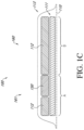
- FIGS. 1A-1C illustrates a wound dressing incorporating the source of negative pressure and/or other electronic components within the wound dressing.
- FIGS. 1A-1C illustrates a wound dressing 100 with the pump and/or other electronics positioned away from the wound site.
- the wound dressing can include an electronics area 161 and an absorbent area 160.
- the dressing can comprise a wound contact layer 110 (not shown in FIGS. 1A-1B ) and a moisture vapor permeable film or cover layer 113 positioned above the contact layer and other layers of the dressing.
- the wound dressing layers and components of the electronics area as well as the absorbent area can be covered by one continuous cover layer 113 as shown in FIGS. 1A-1C .
- the dressing can comprise a wound contact layer 110, a transmission layer 111, an absorbent layer 112, a moisture vapor permeable film or cover layer 113, 113 positioned above the wound contact layer, transmission layer, absorbent layer, or other layers of the dressing.
- the wound contact layer can be configured to be in contact with the wound.
- the wound contact layer can include an adhesive on the patient facing side for securing the dressing to the surrounding skin or on the top side for securing the wound contact layer to a cover layer or other layer of the dressing.
- the wound contact layer can be configured to provide unidirectional flow so as to facilitate removal of exudate from the wound while blocking or substantially preventing exudate from returning to the wound.
- the wound contact layer 110 can be a polyurethane layer or polyethylene layer or other flexible layer which is perforated, for example via a hot pin process, laser ablation process, ultrasound process or in some other way or otherwise made permeable to liquid and gas.
- the wound contact layer 110 has a lower surface and an upper surface.
- the perforations preferably comprise through holes in the wound contact layer 110 which enable fluid to flow through the layer 110.
- the wound contact layer 110 helps prevent tissue ingrowth into the other material of the wound dressing.
- the perforations are small enough to meet this requirement while still allowing fluid to flow therethrough.
- perforations formed as slits or holes having a size ranging from 0.025 mm to 1.2 mm are considered small enough to help prevent tissue ingrowth into the wound dressing while allowing wound exudate to flow into the dressing.
- the wound contact layer 110 may help maintain the integrity of the entire dressing 100 while also creating an air tight seal around the absorbent pad in order to maintain negative pressure at the wound.
- the wound contact layer 110 may also act as a carrier for an optional lower and upper adhesive layer (not shown).
- a lower pressure sensitive adhesive may be provided on the lower surface of the wound dressing 100 whilst an upper pressure sensitive adhesive layer may be provided on the upper surface of the wound contact layer.
- the pressure sensitive adhesive which may be a silicone, hot melt, hydrocolloid or acrylic based adhesive or other such adhesives, may be formed on both sides or optionally on a selected one or none of the sides of the wound contact layer. When a lower pressure sensitive adhesive layer is utilized it may be helpful to adhere the wound dressing 100 to the skin around a wound site.
- the wound contact layer may comprise perforated polyurethane film.
- the lower surface of the film may be provided with a silicone pressure sensitive adhesive and the upper surface may be provided with an acrylic pressure sensitive adhesive, which may help the dressing maintain its integrity.
- a polyurethane film layer may be provided with an adhesive layer on both its upper surface and lower surface, and all three layers may be perforated together.
- a layer 111 of porous material can be located above the wound contact layer 110.
- the terms porous material, spacer, and/or transmission layer can be used interchangeably to refer to the layer of material in the dressing configured to distribute negative pressure throughout the wound area.
- This porous layer, or transmission layer, 111 allows transmission of fluid including liquid and gas away from a wound site into upper layers of the wound dressing.
- the transmission layer 111 preferably ensures that an open air channel can be maintained to communicate negative pressure over the wound area even when the absorbent layer has absorbed substantial amounts of exudates.
- the layer 111 should preferably remain open under the typical pressures that will be applied during negative pressure wound therapy as described above, so that the whole wound site sees an equalized negative pressure.
- the layer 111 may be formed of a material having a three dimensional structure. For example, a knitted or woven spacer fabric (for example Baltex 7970 weft knitted polyester) or a non-woven fabric could be used.
- the transmission layer assists in distributing negative pressure over the wound site and facilitating transport of wound exudate and fluids into the wound dressing.
- the transmission layer can be formed at least partially from a three dimensional (3D) fabric.
- the transmission layer 111 comprises a 3D polyester spacer fabric layer including a top layer (that is to say, a layer distal from the wound-bed in use) which is a 84/144 textured polyester, and a bottom layer (that is to say, a layer which lies proximate to the wound bed in use) which is a 10 denier flat polyester and a third layer formed sandwiched between these two layers which is a region defined by a knitted polyester viscose, cellulose or the like monofilament fiber. Other materials and other linear mass densities of fiber could of course be used.
- top spacer fabric thus has more filaments in a yarn used to form it than the number of filaments making up the yarn used to form the bottom spacer fabric layer.
- This differential between filament counts in the spaced apart layers helps control moisture flow across the transmission layer.
- the top layer is made from a yarn having more filaments than the yarn used in the bottom layer, liquid tends to be wicked along the top layer more than the bottom layer.
- this differential tends to draw liquid away from the wound bed and into a central region of the dressing where the absorbent layer 112 helps lock the liquid away or itself wicks the liquid onwards towards the cover layer 113 where it can be transpired.
- the 3D fabric may be treated with a dry cleaning agent (such as, but not limited to, Perchloro Ethylene) to help remove any manufacturing products such as mineral oils, fats or waxes used previously which might interfere with the hydrophilic capabilities of the transmission layer.
- a dry cleaning agent such as, but not limited to, Perchloro Ethylene
- an additional manufacturing step can subsequently be carried in which the 3D spacer fabric is washed in a hydrophilic agent (such as, but not limited to, Feran Ice 30g/l available from the Rudolph Group). This process step helps ensure that the surface tension on the materials is so low that liquid such as water can enter the fabric as soon as it contacts the 3D knit fabric. This also aids in controlling the flow of the liquid insult component of any exudates.
- an absorbent layer (such as layer 112) for absorbing and retaining exudate aspirated from the wound can be utilized.
- a superabsorbent material can be used in the absorbent layer 112.
- the absorbent includes a shaped form of a superabsorber layer.
- a layer 112 of absorbent material is provided above the transmission layer 111.
- the absorbent material which comprise a foam or non-woven natural or synthetic material, and which may optionally comprise a super-absorbent material, forms a reservoir for fluid, particularly liquid, removed from the wound site.
- the layer 111 may also aid in drawing fluids towards the cover layer 113.
- the material of the absorbent layer 112 may also prevent liquid collected in the wound dressing from flowing freely within the dressing, and preferably acts so as to contain any liquid collected within the dressing.
- the absorbent layer 112 also helps distribute fluid throughout the layer via a wicking action so that fluid is drawn from the wound site and stored throughout the absorbent layer. This helps prevent agglomeration in areas of the absorbent layer.
- the capacity of the absorbent material must be sufficient to manage the exudates flow rate of a wound when negative pressure is applied. Since in use the absorbent layer experiences negative pressures the material of the absorbent layer is chosen to absorb liquid under such circumstances. A number of materials exist that are able to absorb liquid when under negative pressure, for example superabsorber material.
- the absorbent layer 112 may typically be manufactured from ALLEVYN TM foam, Freudenberg 114-224-4 or Chem-Posite TM 11C-450.
- the absorbent layer 112 may comprise a composite comprising superabsorbent powder, fibrous material such as cellulose, and bonding fibers.
- the composite is an airlaid, thermally-bonded composite.
- the absorbent layer 112 is a layer of non-woven cellulose fibers having super-absorbent material in the form of dry particles dispersed throughout.
- Use of the cellulose fibers introduces fast wicking elements which help quickly and evenly distribute liquid taken up by the dressing.
- the juxtaposition of multiple strand-like fibers leads to strong capillary action in the fibrous pad which helps distribute liquid. In this way, the super-absorbent material is efficiently supplied with liquid.
- the wicking action also assists in bringing liquid into contact with the upper cover layer to aid increase transpiration rates of the dressing.
- cover layer and/or backing layer can be used interchangeably to refer to the layer of material in the dressing configured to cover the underlying dressing layers and seal to the wound contact layer and/or the skin surrounding the wound.
- the cover layer can include a moisture vapor permeable material that prevents liquid exudate removed from the wound and other liquids from passing through, while allowing gases through.
- the cover layer 113 is preferably gas impermeable, but moisture vapor permeable, and can extend across the width of the wound dressing 100.
- the cover layer 113 which may for example be a polyurethane film (for example, Elastollan SP9109) having a pressure sensitive adhesive on one side, is impermeable to gas and this layer thus operates to cover the wound and to seal a wound cavity over which the wound dressing is placed. In this way an effective chamber is made between the cover layer 113 and a wound site where a negative pressure can be established.
- the cover layer 113 is preferably sealed to the wound contact layer 110 in a border region around the circumference of the dressing, ensuring that no air is drawn in through the border area, for example via adhesive or welding techniques.
- the cover layer 113 protects the wound from external bacterial contamination (bacterial barrier) and allows liquid from wound exudates to be transferred through the layer and evaporated from the film outer surface.
- the cover layer 113 preferably comprises two layers; a polyurethane film and an adhesive pattern spread onto the film.
- the polyurethane film is preferably moisture vapor permeable and may be manufactured from a material that has an increased water transmission rate when wet.
- the moisture vapor permeability of the cover layer increases when the cover layer becomes wet.
- the moisture vapor permeability of the wet cover layer may be up to about ten times more than the moisture vapor permeability of the dry cover layer.
- the electronics area 161 can include a source of negative pressure (such as a pump) and some or all other components of the TNP system, such as power source(s), sensor(s), connector(s), user interface component(s) (such as button(s), switch(es), speaker(s), screen(s), etc.) and the like, that can be integral with the wound dressing.
- a source of negative pressure such as a pump
- the electronics area 161 can include a button or switch 114 as shown in FIGS. 1A-1B .
- the button or switch 114 can be used for operating the pump (e.g., turning the pump on/off).
- the absorbent area 160 can include an absorbent material 112 and can be positioned over the wound site.
- the electronics area 161 can be positioned away from the wound site, such as by being located off to the side from the absorbent area 160.
- the electronics area 161 can be positioned adjacent to and in fluid communication with the absorbent area 160 as shown in FIGS. 1A-1C .
- each of the electronics area 161 and absorbent area 160 may be rectangular in shape and positioned adjacent to one another.
- the electronics area 161 is noted as area "A" and the absorbent area 160 is noted as area "B".
- FIG. 1C the electronics area 161 is noted as area "A" and the absorbent area 160 is noted as area "B".
- electronic components 150 can be positioned within a recess or cut out of the absorbent material 112 but off to the side of the absorbent area. As shown in the cross sectional view of the wound dressing layers in FIG. 1C , the absorbent material 112 can be positioned on both sides of the electronic components 150.
- additional layers of dressing material can be included in the electronics area 161, the absorbent area 160, or both areas.
- the dressing can comprise one or more transmission or spacer layers and/or one or more absorbent layer positioned above the wound contact layer 110 and below the cover layer 113 of the dressing.
- the electronics area 161 of the dressing can comprise electronic components 150.
- the electronics area 161 of the dressing can comprise one or more layers of transmission or spacer material and/or absorbent material and electronic components 150 can be embedded within the one or more layers of transmission or spacer material and/or absorbent material.
- the layers of transmission or absorbent material can have recesses or cut outs to embed the electronic components 150 within whilst providing structure to prevent collapse.
- the electronic components 150 can include a pump, power source, controller, and/or an electronics package.
- a pump exhaust can be provided to exhaust air from the pump to the outside of the dressing.
- the pump exhaust can be in communication with the electronics area 161 and the outside of the dressing.
- the upper layer, top layer, or layer above refers to a layer furthest from the surface of the skin or wound while the dressing is in use and positioned over the wound.
- the lower surface, lower layer, bottom layer, or layer below refers to the layer that is closest to the surface of the skin or wound while the dressing is in use and positioned over the wound.
- the layers can have a proximal wound-facing face referring to a side or face of the layer closest to the skin or wound and a distal face referring to a side or face of the layer furthest from the skin or wound.
- FIGS. 1A-1C illustrates a wound dressing apparatus incorporating the pump and/or other electronic components within the wound dressing and offset from the absorbent layer.
- the absorbent area 160 comprises a transmission layer 111 positioned above the wound contact layer 110.
- An absorbent layer 112 can be provided above the transmission layer 111.
- the electronics area 161 can include an electronics unit (shown in FIGS. 2A-2B ).
- the electronics unit is provided directly over the wound contact layer.
- the electronics unit can be placed above a layer of wicking material, absorbent material, or transmission material that sits above the wound contact layer 110 of the dressing. For example, as shown in FIG.
- the electronics unit 150 may be positioned over the transmission layer 111.
- the transmission layer 111 can be a single layer of material extending below the electronics unit 150 and the absorbent material 112. Thus, in some embodiments, the transmission layer 111 extends continuously through the absorbent area 160 and the electronics area 161.
- the transmission layer below the electronics unit can be a different transmission layer than the transmission layer below the absorbent material 112.
- the transmission layer 111, absorbent material 112, and electronics unit 150 can be covered with a cover layer 113 that seals to a perimeter of the wound contact layer 110 as shown in FIGS. 1A-1C .
- the electronics area 161 can include an electronics unit 150 positioned below the cover layer 113 of the dressing.
- the electronics unit can be surrounded by a material to enclose or encapsulate a negative pressure source and electronics components by surrounding the electronics. In some embodiments, this material can be a casing.
- the electronics unit can be encapsulated or surrounded by a protective coating, for example, a hydrophobic coating as described herein.
- the electronics unit can be in contact with the dressing layers in the absorbent area 160 and covered by the cover layer 113.
- the electronics unit includes a lower or wound facing surface that is closest to the wound and an opposite, upper surface, furthest from the wound when the wound dressing is placed over a wound.
- FIG. 1C illustrates an embodiment of a wound dressing incorporating an electronics unit 150 within the dressing.
- the electronics sub assembly or electronics unit 150 can be embedded in an aperture or hole in an absorbent layer 112 towards one end of the dressing, as depicted in FIG. 1C .
- the absorbent components and electronics components can be overlapping but offset.
- a portion of the electronics area can overlap the absorbent area, for example overlapping the superabsorber layer, but the electronics area is not completely over the absorbent area. Therefore, a portion of the electronics area can be offset from the absorbent area.
- the dressing layer and electronic components can be enclosed in a wound contact layer 110 positioned below the lower most layer and a cover layer 113 positioned above the absorbent layer 112 and electronics 150.
- the wound contact layer 110 and cover layer 113 can be sealed at a perimeter enclosing the dressing components.
- the cover layer can be in direct physical contact with the absorbent material, and/or the electronics unit.
- the cover layer can be sealed to a portion of the electronics unit and/or casing, for example, in areas where holes or apertures are used to accommodate the electronic components (e.g. a switch and/or exhaust).
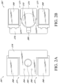
- FIGS. 2A-2B illustrate embodiments of an electronics unit 267 that can be incorporated into a wound dressing.
- FIG. 2A illustrates the top view of the electronics unit.
- FIG. 2B illustrates a bottom or wound facing surface of the electronics unit.
- the electronics unit 267 can include a pump 272 and one or more batteries 268.
- the electronics unit 267 can include a flexible circuit board 276 configured to be in electrical communication with the pump 272 and/or batteries 268.
- the electronics unit 267 can include single button or switch 265 on the upper surface of the unit.
- the single button or switch 265 can be used as an on/off button or switch to stop and start operation of the pump and/or electronic components.
- the switch 265 can be a dome type switch configured to sit on the top of the pump. Because the switch is situated within the dressing the cover layer can be easily sealed around or over the switch. In some embodiments, the cover layer can have an opening or hole positioned above the switch. The cover layer can be sealed to the outer perimeter of the switch 265 to maintain negative pressure under the wound cover.
- the switch can be placed on any surface of the electronics unit and can be in electrical connection with the pump.
- the electronics unit 267 can also include one or more vents or exhausts aperture 264 on the flexible circuit board for expelling the air exhausted from the pump.
- a pump outlet exhaust mechanism 274 can be attached to the outlet of the pump 272.
- the vent or exhaust aperture 264 can be in fluid communication with a pump exhaust mechanism 274 positioned at the outlet of the pump and extending to the lower surface of the flexible circuit board.
- an exhaust vent 264 on the flexible circuit board can provide communication with the top surface of the dressing and allow the pump exhaust to be vented from the electronics unit.
- the exhaust mechanism 274 can be attached to the outlet end of the pump and can extend out from the pump at a 90-degree angle from the pump orientation to communicate with the bottom surface of the flexible circuit board.
- the exhaust mechanism 274 can include an antibacterial membrane and/or a non-return valve.
- the exhaust vent 264 can include an antibacterial membrane and/or a non-return valve.
- the exhausted air from the pump can pass through the pump outlet and exhaust mechanism 274.
- the cover layer 113 can include apertures or holes positioned above the exhaust vent 264 and/or membrane. The cover layer 113 can be sealed to the outer perimeter of the exhaust 264 to maintain negative pressure under the wound cover 113.
- the exhausted air can be exhausted through the gas permeable material or moisture vapor permeable material of the cover layer.
- the cover layer does not need to contain apertures or holes over the exhaust and the exhausted air is expelled through the cover layer.
- the pump outlet mechanism 274 can be a custom part formed to fit around the pump as shown in FIG. 2B .
- the electronic unit 267 can include a pump inlet protection mechanism 280 as shown in FIG. 2C positioned on the portion of the electronic unit closest to the absorbent area and aligned with the inlet of the pump 272.
- the pump inlet protection mechanism 280 is positioned between the pump inlet and the absorbent area or absorbent layer of the dressing.
- the pump inlet protection mechanism 280 can be formed of a hydrophobic material to prevent fluid from entering the pump 272.
- the upper surface of the electronics unit can include one or more indicators 266 for indicating a condition of the pump and/or level of pressure within the dressing.
- the indicators can be small LED lights or other light source that are visible through the dressing components or through holes in the dressing components above the indicators.
- the indicators can be green, yellow, red, orange, or any other color. For example, there can be two lights, one green light and one orange light. The green light can indicate the device is working properly and the orange light can indicate that there is some issue with the pump (e.g. dressing leak, saturation level of the dressing, and/or low battery).
- FIGS. 2A-2B illustrates an embodiment of an electronics unit 267.
- the electronics unit 267 can include a pump 272 and one or more batteries 268 or other power source to power the pump 272 and other electronics.
- the pump can operate at about 27 volts or about 30 volts.
- the two batteries can allow for a more efficient voltage increase (6 volts to 30 volts) than would be possible with a single battery.
- the batteries 268 can be in electrical communication with a flexible circuit board 276.
- one or more battery connections are connected to a surface of the flexible circuit board 276.
- the flexible circuit board can have other electronics incorporated within.
- the flexible circuit board may have various sensors including, but not limited to, one or more pressure sensors, temperature sensors, optic sensors and/or cameras, and/or saturation indicators.
- the components of the electronics unit 267 may include a protective coating to protect the electronics from the fluid within the dressing.
- the coating can provide a means of fluid separation between the electronics unit 267 and the absorbent materials of the dressing.
- the coating can be a hydrophobic coating including, but not limited to, a silicone coating or polyurethane coating.
- the electronics unit 267 can be encapsulated in a protective housing or enclosure as described in more detail herein.
- the pump inlet component can be used to protect the pump from fluid on the inlet and the pump outlet mechanism can include a non-return valve that protects fluid from entering the outlet as described in more detail with reference to PCT International Application No.
- PCT/EP2017/055225 filed March 6, 2017 , titled WOUND TREATMENT APPARATUSES AND METHODS WITH NEGATIVE PRESSURE SOURCE INTEGRATED INTO WOUND DRESSING and PCT International Application No. PCT/EP2017/059883, filed April 26, 2017 , titled WOUND DRESSING AND METHODS OF USE WITH INTEGRATED NEGATIVE PRESSURE SOURCE HAVING A FLUID INGRESS INHIBITION COMPONENT.
- the electronics unit 267 includes one or more slits, grooves or recesses 271 in the unit between the pump and the two batteries.
- the slits, grooves or recesses 271 can allow for the electronics unit 267 to be flexible and conform to the shape of the wound.
- the unit 267 can have two parallel slits, grooves or recesses 271 forming three segments of the electronics unit 267.
- the slits, grooves or recesses 271 of the unit 267 create hinge points or gaps that allows for flexibility of the electronics unit at that hinge point.
- the pump exhaust vent 264, switch 265, and indicator 266 are shown on the top surface of the electronics unit 267.
- one embodiment of the electronics unit 267 has two hinge points to separate the unit into three regions or panels, for example one to contain one battery, one to contain the pump, and one to contain another battery.
- the slits, grooves or recesses may extend parallel with a longitudinal axis of the dressing that extends along the length of the dressing through the electronics area of the dressing through the absorbent area of the dressing.
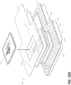
- FIG. 3A illustrates an embodiment of wound dressing layers incorporating the electronic components within the wound dressing.
- FIG. 3A illustrates a wound dressing with a wound contact layer 310 configured to contact the wound.
- a transmission layer or spacer layer 311 is provided over the wound contact layer. The transmission layer 311 can assist in transmitting and distributing negative pressure over the wound site.
- a first layer of apertured absorbent material 351 can be provided over the transmission layer 311.
- the first apertured absorbent layer 351 can include one or more apertures 329.
- the apertures 329 can be sized and shaped to fit the electronics unit 350 therein.
- the first apertured absorbent layer 351 can be sized and shaped to the size of the electronics area and does not extend into the absorbent area.
- the apertures 329 can be shaped and sized to fit the individual components of the electronics unit 350.
- a second apertured absorbent layer 322 can be provided over the first absorbent layer 351.
- the second absorbent layer 322 includes one or more apertures 328.
- the second absorbent layer 322 can be sized and shaped to the size of the electronics area and the absorbent area.
- the apertures 328 can be shaped and sized to fit the individual components of the electronics unit 350.
- An electronics unit 350 can be positioned in the apertures 328 and 329 of the first and second absorbent material 351 and 322.
- the electronics unit 350 can include a pump 327, power source 326, and a printed circuit board 381.
- the pump 327 can include a pump inlet mechanism 710 and an outlet mechanism 382.
- the printed circuit board 381 can include electronics including but not limited to a switch, sensors, and LEDs as described herein.
- the circuit board 381 can include one or more hole to be positioned over one or more exhaust vents (not shown) in the outlet mechanism 382 as described in more detail herein.
- An overlay layer 317 can be provided over the electronics components 350 and absorbent layer 322.
- the overlay layer 317 can be one or more layers of absorbent and/or transmission material as described herein.
- the overlay layer 317 can comprise a conformable material overlaying and overbordering the perimeter of the lower layers of transmission and absorbent materials.
- the overlay layer 317 can soften the edges of the wound dressing layers by decreasing the profile around the edges of the dressing layers.
- the overlay layer 317 can protect the cover layer from being punctured by the lower layers when the cover layer is sealed over the dressing layers below.
- the overlay layer 317 can include an aperture 371 to allow access to at least a portion of the electronics unit 350 positioned below.
- a cover layer or backing layer 313 can be positioned over the overlay layer 317.
- the cover layer or backing layer 313 can be provided above absorbent layers 322, and/or electronic components 350.
- the cover layer 313 can form a seal to the wound contact layer 310 at a perimeter region enclosing the overlay layer 317, absorbent layers 322 and 351, electronic components 350, and the transmission layer 311.
- the cover layer 313 can be a flexible sheet of material that forms and molds around the dressing components when they are applied to the wound.
- the cover layer 313 can be a material that is preformed or premolded to fit around the dressing components as shown in FIG. 3A .
- the terms cover layer and backing layer can be used interchangeably to refer to the layer of material in the dressing configured to cover the layers of the wound dressing.
- the cover layer or backing layer 313 can include an aperture 372.
- the aperture 372 can be positioned over at least a portion of the aperture 371 in the overlay layer 317 to allow access to at least a portion of the electronics unit 350 positioned below.
- the apertures 371 and 372 can allow access to the switch and/or venting holes of the pump exhaust.
- a label 341 can be provided over the apertures 371 and 372 and positioned over the exposed portion of the electronic components 350.
- the label can include the vent holes 342, indicator portions 344, and/or switch cover 343.
- the indicator portions 344 can include holes or transparent regions 344 for positioning over the one or more indicators or LEDs on the printed circuit board 381 below the label 341.
- the holes or transparent regions 344 can allow for the indicators or LEDs to be visible through the label 341.
- the switch cover 342 can include a dome shaped cover positioned over the switch on the printed circuit board 381.
- the label 341 can include embossed features for the switch cover 342.
- the embossed features of the switch cover 342 can prevent accidental activation or deactivation of the device.
- the switch or switch cover 342 can include a tab on the switch to prevent accidental activation or deactivation.
- the vent holes 342 of the label can allow exhaust from the pump outlet mechanism to pass through the label and exit the wound dressing to be exhausted to the atmosphere.
- the label can be positioned on top of the cover layer or backing layer 313.
- the label can seal to the cover layer to form a seal over the wound.
- the label 341 can be positioned above the overlay layer 371 and below the cover layer or backing layer 313.
- the cover layer 313 can have one or more apertures over one or more components of the label 341.
- the cover layer 313 can have apertures over the vent holes 342, indicator portions 344, and/or switch cover 343.
- FIG. 3B illustrates a cross sectional layout of the material layers of the wound dressing incorporating an electronics assembly within the dressing.
- the dressing 300 included multiple material layers and an electronics assembly 350.
- the wound dressing 300 can include an electronics area 361 including the electronics and an absorbent area or dressing area 360 that is intended to be applied to the wound as described with reference to FIGS. 1A-1C .
- the one or more material layers can extend into both the electronics area 361 and the dressing area 360.
- the dressing 300 can include a wound contact layer 310, transmission layer 311, absorbent layers 322 and 351, an overlay layer 317, and a cover or backing layer 313 as illustrated in FIG. 3B .
- the absorbent layers 322 and 351 can include recesses or cutouts to receive the components of the electronics assembly 350 as described herein.
- the small apertured absorbent layer 351 can be positioned on top of the large apertured absorbent layer 322.
- the small apertured absorbent layer 351 can be positioned on below of the large apertured absorbent layer 322.
- the overlay layer 317 and/or the cover layer 313 can include a cut out or aperture positioned over the switch and/or indicators of the electronics assembly 350.
- a label or covering 341 can be positioned to over at least a portion of the electronics assembly 350 and any cutouts in the overlay layer 317 and/or the cover layer 313.
- the label or covering 341 can be similar to the label or covering 341 as described previously with reference to FIG. 3A .
- the dressing can include a delivery layer 345 adhered to the bottom surface of the wound contact layer.
- the delivery layer 345 can cover adhesive or apertures on the bottom surface of the wound contact layer 310.
- the delivery layer 345 can provided support for the dressing and can assist in sterile and appropriate placement of the dressing over the wound and skin of the patient.
- the delivery layer 345 can include handles 346 that can be used by the user to separate the delivery layer 345 from the wound contact layer 310 before applying the dressing 300 to a wound and skin of a patient.
- FIG. 3C illustrates a top view of an embodiment of the wound dressing incorporating an electronic assembly within the dressing.
- FIG. 3C shows a cover layer 313 and electronics covering 341 covering the overlay layer 317 and underlying dressing and electronics components.
- the cover layer 313 can seal to the wound contact layer 310 at a perimeter region of the wound contact layer 310.
- the label or electronics covering 341 can be positioned over the cover layer 313.
- the cover layer 313 can seal over the electronics covering 341.
- the cover layer 313 can include one or more holes in the cover layer 313 positioned over the switch and/or pump outlet vent(s).
- the cover layer 313 can include a single hole that is positioned over the switch cover 343, visual indicators 344, and/or pump outlet vent(s) 342 in the covering or label 341 as shown in FIG. 3C .
- the label can include embossed features for the switch cover 343.
- the embossed features of the switch cover 343 can prevent accidental activation or deactivation of the device.
- the switch or switch cover 343 can include a tab on the switch to prevent accidental activation or deactivation.
- the visual indicators 344 can provide an indication of operation of the negative pressure source and/or an indication of the level of negative pressure that is applied to the wound.
- the visual indicators can include one or more light sources or LEDs.
- the visual indicator light sources an illuminate to indicate a condition or change of condition.
- the light source can illuminate in a particular sequence and/or color that indicates a condition.
- the light source can flash to notify the user that the device is operating properly.
- the light source can automatically flash periodically and/or the light source can be activated by the switch or other button to light up and indicate a condition.
- the switch can be pressed and/or held down to power the dressing and electronics on and off.
- the pump and associated colored LED for example, green colored LED
- the pump and dressing can enter the fault state indicated by a colored LED, for example, orange colored LED.
- FIG. 4 illustrates a negative pressure therapy system 400 that includes a TNP apparatus 11 applicable on a wound 14 according to some embodiments.
- the TNP apparatus 11 can be used to treat the wound 14.
- the TNP apparatus 11 can include controller 12A, memory 12B, a negative pressure source 12C, a user interface 12D, a power source 12E, a first pressure sensor 12F, and a second pressure sensor 12G that are configured to electrically communicate with one another.
- the TNP apparatus 11 can include a wound dressing 13.
- the power source 12E can provide power to one or more components of the TNP apparatus 11.
- One or more of the controller 12A, memory device 12B, negative pressure source 12C, user interface 12D, power source 12E, first pressure sensor 12F, and second pressure sensor 12G can be integral with, incorporated as part of, attached to, or disposed in the wound dressing 13.
- the TNP apparatus 11 can accordingly be considered to have its control electronics and pump on-board the wound dressing 13 rather than separate from the wound dressing 13.
- the controller 12A may be a microcontroller or microprocessor.
- the controller 12A can control the operations of one or more other components of the TNP apparatus 11 according at least to instructions stored in the memory device 12B.
- the controller 12A can, for instance, control operations of and supply of negative pressure by the negative pressure source 12C.
- the controller 12A can be a primary controller, and the TNP apparatus 11 can include one or more additional controllers as described herein.
- the negative pressure source 12C can include a pump, such as, without limitation, a rotary diaphragm pump or other diaphragm pump, a piezoelectric pump, a peristaltic pump, a piston pump, a rotary vane pump, a liquid ring pump, a scroll pump, a pump operated by a piezoelectric transducer, or any other suitable pump or micropump or any combinations of the foregoing.
- the pump can include an actuator driven by a source of energy, such as electrical energy, mechanical energy, and the like.
- the actuator can be an electric motor, a piezoelectric transducer, a voice coil actuator, an electroactive polymer, a shape-memory alloy, a comb drive, a hydraulic motor, a pneumatic actuator, a screw jack, a servomechanism, a solenoid actuator, a stepper motor, a plunger, a combustion engine, and the like.
- the negative pressure source 12C can supply negative pressure by converting electrical energy to mechanical energy without converting the electrical energy to magnetic energy.
- the negative pressure source 12C can have a different impact when electrically coupled to one or more other components of the controller 12A than if the negative pressure source 12C supplied negative pressure by converting the electrical energy to the magnetic energy and then to the mechanical energy.
- the user interface 12D can include one or more elements that receive user inputs or provide user outputs to a patient or caregiver.
- the one or more elements that receive user inputs can include buttons, switches, dials, touch screens, or the like, and the one or more elements that provide user outputs can include activation of a light emitting diode (LED) or one or more pixels of the display or activation of a speaker or the like.
- the user interface 12D can include a switch to receive user inputs (for instance, a negative pressure activation or deactivation input) and two LEDs to indicate an operating status (for example, functioning normally, under fault condition, or awaiting user input) of the TNP apparatus 11.
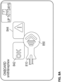
- the user interface 12D may also include input elements that change the state of the controller 12A by employing switching mechanisms, such as a pull tab (further described with respect to FIG. 8A and 8B ).
- the first pressure sensor 12F can be used to monitor pressure underneath the wound dressing 13, such as pressure in a fluid flow path connecting the negative pressure source 12C and the wound 14, pressure at the wound 14, or pressure in the negative pressure source 12C.
- the second pressure sensor 12G can be used to monitor pressure external to the wound dressing 13.
- the pressure external to the wound dressing can be atmospheric pressure; however, the atmospheric pressure can vary depending on, for instance, an altitude of use or pressurized environment in which the TNP apparatus 11 may be used.
- the controller 12A can control the supply of negative pressure by the negative pressure source 12C according at least to a comparison between the pressure monitored by the first pressure sensor 12F and the pressure monitored by the second pressure sensor 12G.
- the wound dressing 13 can include a wound contact layer, a spacer layer, and an absorbent layer.
- the wound contact layer can be in contact with the wound 14.
- the wound contact layer can include an adhesive on the patient facing side for securing the dressing to the skin surrounding the wound 14 or on the top side for securing the wound contact layer to a cover layer or other layer of the wound dressing 13.
- the wound contact layer can provide unidirectional flow so as to facilitate removal of exudate from the wound while blocking or substantially preventing exudate from returning to the wound 14.
- the spacer layer can assist in distributing negative pressure over the wound site and facilitating transport of wound exudate and fluids into the wound dressing 13.
- the absorbent layer can absorb and retain exudate aspirated from the wound 14.
- the controller 12A can monitor the activity of the negative pressure source 12C, which may include monitoring a duty cycle of the negative pressure source 12C (for example, the duty cycle of the actuator of the negative pressure source).
- a duty cycle of the negative pressure source 12C for example, the duty cycle of the actuator of the negative pressure source.
- the "duty cycle” can reflect the amount of time the negative pressure source 12C is active or running over a period of time. In other words, the duty cycle can reflect time that the negative pressure source 12C is in an active state as a fraction of total time under consideration.
- Duty cycle measurements can reflect a level of activity of the negative pressure source 12C. For example, the duty cycle can indicate that the negative pressure source 12C is operating normally, working hard, working extremely hard, etc.
- the duty cycle measurements can reflect various operating conditions, such as presence or severity of leaks, rate of flow of fluid (for instance, air, liquid, or solid exudate, etc.) aspirated from a wound, or the like.
- the controller can execute or be programmed to execute algorithms or logic that control the operation of the system.
- duty cycle measurements can indicate presence of a high leak, and the controller 12A can be programmed to indicate this condition to a user (for instance, patient, caregiver, or physician) or temporarily suspend or pause operation of the source of negative pressure in order to conserve power.
- the wound dressing 13 can create a substantially sealed or closed space around the wound 13 and under the wound dressing 13, and the first pressure sensor 12F can periodically or continuously measure or monitor a level of pressure in this space.
- the controller 12A can control the level of pressure in the space between a first negative pressure set point limit and at least a second negative pressure set point limit.
- the first set point limit can be approximately -70 mmHg, or from approximately -60 mmHg or less to approximately -80 mmHg or more.
- the second set point limit can be approximately -90 mmHg, or from approximately -80 mmHg or less to approximately -100 mmHg or more.
- the controller 12A may operate the negative pressure source 12C such that a lower pressure is maintained at the first pressure sensor 12F than at outside atmosphere at the second pressure sensor 12G.
- TNP systems come in various sizes, from small to large. Also, as described here, such as in connection with FIGS. 1A-3C , some TNP systems have electronics and power source integrated in the dressing. These integrated systems can advantageously have quieter and easier application or operation, increased portability, reduced maintenance efforts, simpler aesthetics, or the like. However, although integrated TNP systems carry these and other numerous advantages, safe production and operation of the systems may pose a unique challenge when it comes to sterilization of the system.
- TNP systems are applied on wounds, it is important that the systems and its components are free from bacteria. A risk of bacterial infection may undermine the wound healing purpose of the TNP systems.
- sterilization is simpler matter as the dressing may be sterilized separately from the pump and pump electronics.
- the dressing, pump, and pump electronics can be sterilized with low temperature sterilization techniques such as passing an antibacterial gas through the dressing.
- ethylene oxide (EtO) can be used for sterilization as it is a colorless gas that effectively attacks the cellular proteins and nucleic acids of microorganisms.
- the sterilized dressing may be applied on or near to wounds, the negative pressure pumps may later be connected to the dressing, and the activated for operation.
- sterilization of the integrated negative pressure wound therapy systems is not a simple matter. Because the power source, the electronics, and negative pressure source can be positioned in or on the dressing, using same or similar sterilization techniques as for non-integrated TNP systems may expose other components to the sterilizing gas. This exposure can be problematic because EtO is flammable.
- non-integrated devices can be powered using replaceable batteries.
- the batteries can be disconnected from the electronics such that the electronics are unpowered and therefore cannot have stored energy that may present a hazard for igniting EtO during sterilization.
- integrated systems include a non-removable power source that is positioned in or on the wound dressing.
- a non-removable power source that is positioned in or on the wound dressing.
- the power source can be isolated from the rest of electronics in integrated TNP systems such that unwanted release of energy is avoided. This can be accomplished through isolating the power source from the electronics during sterilization and including two (or more) activation circuits configured to, respectively, couple a decoupled power source to the electronics and activate operation of the TNP system. Certain implementations refer to such arrangements as two-step activation.
- FIG. 5 illustrates a block diagram 500 of a TNP system configured to isolate an electronic circuitry from a power source according to some embodiments.
- the system 500 includes the power source 12E, electronic circuitry 30, and the negative pressure source 12C.
- the electronic circuitry 30 includes the controller 12A, an isolation circuit 32, an operation switch 33, and one or more capacitors 35. As described herein, activation of the operation switch 33 can activate the controller 12A and activate charging of the one or more capacitors 35, which will store energy and can supply energy (for example, current) to the negative pressure source 12C.
- FIG. 5 illustrates how the isolation circuit 32 can prevent the power source 12E from electrically coupling with the rest of the electronic circuitry 30 according to some embodiments.
- the power source 12E can include one or more power supplies, such as batteries (which may be boosted, AC and/or DC) to provide power for one or more components of the TNP apparatus, such as the TNP apparatus 11, including the electronic circuitry 30 and the negative pressure source 12C.
- the power source 12E can, for instance, provide electrical current and voltage to the isolation circuit 32.
- the voltage output by the power source 12E can include one or more of around 3 V, 6 V, 27 V, or the like in some implementations.
- the power source 12E and/or electronic circuitry 30 can additionally include circuitry, such as a boost converter, to control the provided electrical current and voltage. In some implementations, a power conversion is performed between the one or more capacitors 35 and the negative pressure source 12C.
- the boost converter can increase the output of the power source 12E to charge the one or more capacitors 35 and/or power the negative pressure source.
- the boost converter may not boost the output of the power source, but instead control a therapy device and/or control one or more sensors of the system.
- the boost converter can operate as a secondary power controller (in addition to the primary controller).
- the secondary power controller can turn on/off the source of negative pressure and/or another therapy device, such as an ultrasound generator, oxygen concentrator, cold plasma generator, or the like.
- the isolation circuit 32 can isolate the power source 12E from electrically coupling with the rest of the electronic circuitry 30.
- the isolation circuit 32 operates in two or more states.
- the isolation circuit 32 operates as an open circuit, which prevents the output of the power source 12E to be supplied to the other components of the electronic circuitry 30.
- the one or more capacitors 35 cannot store any charge, which prevents accidental overheating, sparking, and/or igniting EtO during sterilization even if the operation switch 33 is inadvertently activated.
- the isolation circuit 32 allows the output of the power source 12E to be supplied to the other components of the electronic circuitry 30, which can result in the one or more capacitors 35 storing electrical energy.
- the isolation circuit 32 When the isolation circuit 32 is in the first "off” state, the isolation circuit 32 does not provide the negative pressure source 12C with power from the power source 12E. On the other hand, when the isolation circuit 32 is in the second "on” state, depending on the state of the operation switch 33, operation power may be provided to the negative pressure source 12C for provision of negative pressure wound therapy.
- the operation switch 33 is electrically connected to the power source 12E and the negative pressure source 12C and is located between the two.
- the operation switch 33 may operate in two or more states. In first "off” state, the operation switch 33 prevents operation of the negative pressure source 12C. In second “on” state, the operation switch 33 allows the operation of the negative pressure source 12C. In some cases, the operation switch 33 may be located closer to or further from the power source 12E than the isolation circuit 32.
- switching the state of isolation circuit 32 to the "on” state may represent step 1 of activation.
- Switching the state of operation switch 33 to the "on” state may represent step 2 of activation.
- the steps may form two-step activation that provides safe sterilization of integrated TNP systems.
- step 1 when the isolation circuit 32 is in the first "off" state, because no power is received or seen by the rest of the components of the electronic circuitry 30, activating the operation switch 33 would not power one or more of the other components.
- each state of the operation switch 33 activates (operation switch 33 “on”) or deactivates (operation switch 33 “off”) the operation of one or more of the controller 12A, one or more capacitors 35, or the negative pressure source 12C.
- the controller 12A can receive power from the power source 12E regardless of the state of the isolation circuit. The controller 12A can operate in a low power mode until the isolation circuit 32 transitions to the "on" state. When the isolation circuit 32 is on the "off' state, power may not be provided to the boost converter as described herein.
- the controller 12A controls operation of the negative pressure source 12C by outputting one or more control signals to one or more inputs of a driving circuit (not shown), which is electrically coupled with the negative pressure source 12C.
- the controller 12A can vary a pulse width modulation (PWM) of output control signals to adjust an electrical current or voltage provided by the driving circuit to the negative pressure source 12C.
- PWM pulse width modulation
- the one or more capacitors 35 are illustrated as example components that can store electrical energy, it should be understood that the capacitors are not the only type of component that can store electrical energy. Depending on possible circuit variations embodying the ideas in this present disclosure, other energy storing components may be alternatively or additionally used. In some cases, the one or more capacitors 35 may be placed to shunt away and conceal current fluctuations, provide power factor correction, provide AC coupling or decoupling, suppress noise and spikes, tune circuits, and/or any other purpose capacitors are used in a circuit.
- FIGS. 6A and 6B illustrate circuit diagrams of electronic circuitry of a negative pressure wound therapy system according to some embodiments.
- a circuit 600A includes a power source 610 and terminals or pins LAT_IN 612 (representing "latching circuit pin in”) and LAT_OUT 614 (representing "latching circuit pin out") for connecting an isolation circuit 600B as illustrated in FIG. 6B (which can be the same or similar to the isolation circuit 32 of FIG. 5 ).
- the power source 610 illustrated as two batteries CELL 1 and CELL 2 is connected to pin 612.
- the isolation circuit 600B when the isolation circuit 600B is in the "on" state (or activated), current flows between the pins 612 and 614.
- an operation switch (not illustrated) is activated (or in the "on” state)
- switch 620 (illustrated as a transistor) is turned on, which allows the one or more capacitors (not shown) to be charged from the power source 610.
- switch 620 If the isolation circuit 600B is in the "off' state (or deactivated), current does not flow between the pins 612 and 614. Regardless of the state of the operation switch, switch 620 will not be turned on and the one or more capacitors will not be charged when the isolation circuit 600B is deactivated. As described herein, this operation reduces the risk of energy stored by, for example, one or more capacitors, overheating, creating a spark, and/or igniting sterilization gas during sterilization of the whole integrated TNP systems.
- FIG. 6B provides an isolation circuit 600B according to some embodiments.
- the circuit 600B can be connected between the pins LAT_IN 612 and LAT_OUT 614 of FIG. 6A .
- the circuit 600B includes an activation switch or another mechanism 630, such as a pull tab, for activating the circuit.
- switches 640 and 650 are closed or off such that no current flows between the pins 612 and 614.
- an electrical path is provided (for example, to ground) permitting current to flow. This can activate switch 650, which allows current to flow between the pins 612 and 614.
- switch 650 can be PFET transistor (for example, PMOS transistor) activated (such as, becoming electrically conductive) when current flows from the pin 612 (connected to the power source 610 as illustrated in FIG. 6A ) through the electrical path provided by the activated activation switch 630.
- the current can activate the switch 650 (for example, PFET transistor), and the switch 650 can provide an electrical path between pins 612 and 614 for the current.
- Activation of switch 650 in turn can cause switch 640, which can be NFET transistor (for example, NMOS transistor) as is illustrated, to be activated (such as, become electrically conductive).
- switch 650 Once switch 650 is activated, current can flow between the pins 612 and 614, thereby allowing switch 620 to be turned on as described herein.
- power is provided to the boost converter. For example, this can result in charging of one or more energy storing components, such as one or more capacitors, that can power the source of negative pressure.
- isolation circuit 600B is a self-latching circuit.
- the circuit 600B can operate so that once the activation switch 630 has been activated, the circuit 600B remains activated allowing current to flow between the pins 612 and 614 even if the activation switch 630 is subsequently deactivated. In such cases, once switches 650 and 640 are activated and power continues to be applied to the pin 612, the circuit 600B is not configured to be reset so that the circuit will continue to operate in the "on" state. Power may be continuously applied to the pin 612 by a permanently connected battery or another power source. In some cases, latching is provided by activating the switch 640 as described herein.
- the switch 640 (for example, NFET transistor) can remain activated regardless of the state of the activation switch 630.
- the switch 640 can provide an electrical path for the current (for example, to ground) necessary to maintain the switch 650 activated even if the activation switch 630 is deactivated and no longer provides an electrical path for the current.
- the switch 640 can remain activated because source of the NFET transistor is connected to the ground, which maintains the transistor in active state when voltage is applied to the gate from the pin 612.
- isolation circuit 600B provides electric connection between pins 612 and 614
- a user of the TNP system may activate an operation switch (such as switch 32 of FIG. 5 ) to cause the controller 12A to wake up and turn switch 620 on, which will allow one or more capacitors (such as the one or more capacitors 35 of FIG. 5 ) to be charged.
- an operation switch such as switch 32 of FIG. 5
- capacitors such as the one or more capacitors 35 of FIG. 5
- pull tab 630 may be replaced by other activation mechanisms, such as one or more buttons.
- the activation mechanism 630 can be a power source, such as a secondary power source that can be additional to the power source described herein (which can serve as a primary power source).
- the secondary power source can have a larger capacity than the primary power source. Connecting or plugging in the secondary power source can present a greater risk of overheating, creating a spark, and/or igniting sterilization gas during sterilization of the TNP apparatus.
- the state of the isolation circuit 600B can be communicated to the user using one or more indicators (for example, the one or more indicators 266).
- inactive state of the isolation circuit can be indicated to the user. This can prompt the user attempting to start provision of negative pressure wound therapy to activate the isolation circuit, for instance, by pulling the pull tab, pressing a button, activating a switch, connecting or plugging in the secondary power source, or the like.
- active state of the isolation circuit can be indicated to the user. This can indicate to the user that the activation was successful.
- FIG. 7 illustrates a back view of a printed circuit board (PCB) 700 configured to perform two-step activation according to some embodiments.
- the PCB 700 includes an activation switch 715, which can be operated by a pull tab, and an operation switch 720.
- Switch 715 includes conductive "fingers” or paths, which are not electrically connected when an isolation circuit is in the "off” state.
- a pull tab 810 FIG. 8A
- the multitude of fingers of the switch 715 can ensure that electrical connection is made when the pull tab 810 is pulled out.
- This type of structure may be used with step 1 activation (for example, activation of the isolation circuit 32 of FIG. 5 ) after sterilization has been completed.
- FIG. 7 illustrates the switch 715 that cannot be deactivated after activation as the conductive fingers remain in electrical contact after the pull tab 810 has been pulled by a user.
- switch 715 is configured for an irreversible activation (for example, it is not easy to de-compress the fingers such that they are no longer electrically connected)
- reversible activation mechanisms may also be used as described herein.
- other types of activation/switching mechanisms may be used based on various engineering or aesthetic considerations.
- the PCB 700 also illustrates a backside of the operation switch 720 (described as 33 in FIG. 33) configured for step 2 activation. Its frontside can be a dome-type switch 820 as shown in FIG. 8B . Pressing the dome switch activates or deactivates step 2 of the two-step activation.
- FIGS. 8A and 8B illustrate front view of the two-step activation PCB with a pull tab before and after a pullout, respectively, according to some embodiments.
- the pull tab 810 is removed to reveal the dome-type switch 820, thereby reducing the likelihood that the two-step activation may be executed in a reverse order.
- removal of the pull tab 810 causes removal of isolating material 830 from the surface of the switch 715 ( FIG. 7 ) so that electrical connection is formed between the fingers of the switch.
- indicators 842 and 844 that can indicate the state of operation of the TNP apparatus.
- the pull tab 810 includes a pattern 850 instructing the user to pull the tab in a particular direction (for example, to the left in the illustrated embodiment).
- FIGS. 9A and 9B illustrate various designs of the shapes and patterns of the pull tab, such as the pull tab 810, according to some embodiments.
- FIG. 9C illustrates a pull tab 910 according to some embodiments.
- Pull tab 910 can be used with any of the embodiments of the activation switch described herein, such as the switch 715.
- Pull tab 910 includes a region 930 that is configured to be in contact with the activation switch, such as the switch 715, when the pull tab is positioned on the PCB (see, for example, FIGS. 7 and 8A ).
- the region 930 can include conductive material that is applied to the conductive paths of the activation switch to activate the switch when the pull tab 910 is pulled out.
- the region 930 can be positioned in contact with the fingers of the switch 715.
- conductive material is applied to the fingers causing the two sets of the fingers come in electrical contact with each other. This cases the isolation circuit to be in the "on" state.
- the pull tab 910 also includes a pattern 950 directing the user to pull to the left.
- the pull tab 910 includes a region 942 that can be coated with adhesive material in order to prevent inadvertent activation by keeping the pull tab 910 attached to the PCB before it is pulled by a user (see, for example, FIGS. 8A-8B ).
- conductive material in the region 930 includes silver, which can be applied to or deposited in the region 930 as silver ink.
- silver ink from the region 930 can be applied across the activation switch to complete step 1 of the activation.
- application of the silver ink from the region 930 to the conductive fingers of the switch can create one or more short circuits across the fingers causing the switch 715 to turn on.
- a single or multiple layers of silver ink can be printed in the region 930.
- conductive materials, formulations, or compounds can be deposited in the region 930. This can include carbon, gold, palladium, or the like. In some cases, it may be advantageous to use material, formulation, or compound that does not easily oxidise.
- the pull tab 910 can be made of plastic.
- Conductive material in the region 930 can be applied to the plastic material by a suitable technique, such as screen printing, inject printing, sputtering, electro-depositing, plating, thin film bonding, or the like.
- an activation switch can be turned off (instead of being turned on) during step 1 of activation. In such cases, pulling a pull tab can cause the activation switch to cease conducting.
- additional or alternative force or forces can be applied to complete step 1 of the activation. Such forces can include pushing, pressing, or the like.
- FIG. 10 illustrates a front view of a two-step activation PCB according to some embodiments.
- a dome-type switch 1010 is used for step 1 activation
- another dome-type switch 1020 is used for step 2 activation.
- step 1 activation with the first switch 1010 may be timed, such that the step 2 activation with switch 1020 may need to be pressed within certain time of activating switch 1010 of step 1.
- either or both of the steps may require pressing and holding the dome-type switches 1010 and/or 1020 for an extended period of time for activations.
- the two steps may be merged into one switch differentiating the activation steps based on duration of the press. For instance, a prolonged press of the switch may perform step 1 activation, followed by a short press to perform step 2 activation.
- various types of switches with various operating mechanisms may be employed for the two-step activation.
- FIG. 11 illustrates wound dressing layers incorporating the electronics components within the wound dressing according to some embodiments.
- the dressing layers and components of FIG. 11 can be similar to the dressing layers and components described in FIGS. 1A-1C or in any other embodiments described herein.
- FIG. 11 illustrates a wound dressing with a wound contact layer 810 configured to contact the wound.
- the wound contact layer 810 can be a similar material and have a similar function as the wound contact layer described with reference to FIGS. 1A-1C .
- a transmission layer or spacer layer 811 is provided over the wound contact layer.
- the transmission layer or spacer layer 811 can be a similar material and have a similar function as the transmission layer or spacer layer described with reference to FIGS. 1A-1C .
- the transmission layer 811 can assist in transmitting and distributing negative pressure over the wound site.
- a first layer of apertured absorbent material 851 can be provided over the transmission layer 811.
- the first apertured absorbent layer 851 can include one or more apertures 829.
- the aperture 829 can be sized and shaped to fit an electronics assembly and/or electronics unit therein.
- the first apertured absorbent layer 851 can be sized and shaped to the size of the electronics area 861 and does not extend into the absorbent area 860.
- the aperture 829 can be shaped and sized to fit the electronics assemblies as described herein.
- a second apertured absorbent layer 822 can be provided over the first absorbent layer 851.
- the second absorbent layer 822 includes one or more apertures 828.
- the second absorbent layer 822 can be sized and shaped to the size of the electronics area 861 and the absorbent area 860.
- the aperture 828 can be shaped and sized to fit the electronics assemblies as described herein.
- the first and second absorbent layers 851 and 822 can be a similar material and have a similar function as the absorbent layer described with reference to FIGS. 1A-1C .
- a cover layer or backing layer 813 can be positioned over the absorbent material 822.
- the cover layer or backing layer 813 can be a similar material and have a similar function as the cover layer or backing layer described with reference to FIGS. 1A-1C .
- the cover layer 813 can form a seal to the wound contact layer 810 at a perimeter region enclosing the absorbent layers 822 and 851 and the transmission layer 811.
- the cover layer 813 can be a flexible sheet of material that forms and molds around the dressing components when they are applied to the wound.
- the cover layer 813 can be a material that is preformed or premolded to fit around the dressing components as shown in FIG. 11 .
- the terms cover layer and backing layer can be used interchangeably to refer to the layer of material in the dressing configured to cover the layers of the wound dressing.
- the cover layer or backing layer 813 can include an aperture 872.
- the aperture 372 can be positioned over at least a portion of the aperture 828 in the absorbent layer 822 to allow access and fluid communication to at least a portion of the absorbent layers 822 and 851, transmission layer 811, and would contact layer 810 positioned below.
- An electronics assembly can be positioned in the apertures 828, 829, and 872 of the first and second absorbent material 851 and 822 and the cover layer 813.
- the electronics assembly can include a pump, power source, and a printed circuit board as described herein.
- the dressing can include one or more delivery layers 846 adhered to the bottom surface of the wound contact layer.
- the delivery layer 846 can cover adhesive or apertures on the bottom surface of the wound contact layer 810.
- the delivery layer 846 can provided support for the dressing and can assist in sterile and appropriate placement of the dressing over the wound and skin of the patient.
- the delivery layer 846 can include handles that can be used by the user to separate the delivery layer 846 from the wound contact layer 810 before applying the dressing to a wound and skin of a patient.
- FIG. 12A illustrates a wound dressing incorporating an electronics assembly 900 within the wound dressing layers 990 according to some embodiments.
- the electronics assembly 900 can be provided within the aperture 872 in the cover layer and apertures 829 and 828 in the first and second absorbent layers.
- the electronics assembly 900 can seal to the outer perimeter of the aperture 872 of the cover layer.
- the electronics assembly 900 can include the pump inlet protection mechanism extending from and sealed to the film as described herein.
- the electronics assembly 900 can be positioned within the apertures 872, 829, 828 in the cover layer and absorbent layer(s) as shown in FIG. 12A .
- the perimeter of the electronics assembly 900 can be sealed to a top surface of the outer perimeter of the aperture 872 in the cover layer as shown in FIG. 12A .
- the electronics assembly 900 is sealed to the cover layer 813 with a sealant gasket, adhesive, heat welding, adhesive bonding, ultrasonic welding, RF welding, or any other attachment or bonding technique.
- the electronics assembly 900 can be permanently sealed to the cover layer 813 and could not be removed from the cover layer without destroying the dressing.
- the electronics assembly 900 can be utilized in a single dressing and disposed of with the dressing. In other embodiments, the electronics assembly 900 can be utilized in a series of dressings.
- FIG. 12B illustrates a cross sectional layout of the material layers of the wound dressing incorporating an electronics assembly within the dressing according to some embodiments.
- the dressing included multiple material layers and an electronics assembly 900.
- the wound dressing can include an electronics area 961 including the electronics and an absorbent area or dressing area 960 that is intended to be applied to the wound as described with reference to FIGS. 1A-1C .
- the one or more material layers can extend into both the electronics area 961 and the dressing area 960.
- the dressing can include a wound contact layer 810, transmission layer 811, absorbent layers 822 and 851, and a cover or backing layer 813 as illustrated in FIG. 12B .
- the absorbent layers 822 and 851 and cover layer 813 can include recesses or cutouts to receive the components of the electronics assembly 900 as described with reference to FIG. 12A .
- the small apertured absorbent layer 851 can be positioned on top of the large apertured absorbent layer 822. In other embodiments, as illustrated in Figures 9A-9B the small apertured absorbent layer 851 can be positioned below of the large apertured absorbent layer 922.
- the electronics assembly 900 can be inserted and affixed in the dressing layers. As illustrated in FIG. 12A , the lower wound facing face of the film enclosing the electronics assembly can be sealed directly to the upper surface of the cover layer 813 of the dressing.
- the dressing can include a delivery layer 846 adhered to the bottom surface of the wound contact layer 810.
- the delivery layer 846 can cover adhesive or apertures on the bottom surface of the wound contact layer 810.
- the delivery layer 846 can provided support for the dressing and can assist in sterile and appropriate placement of the dressing over the wound and skin of the patient.
- the delivery layer 846 can include handles that can be used by the user to separate the delivery layer 846 from the wound contact layer 810 before applying the dressing to a wound and skin of a patient.
- FIG. 13 illustrates a wound dressing incorporating an electronics assembly within the dressing layers according to some embodiments.
- the wound dressing comprises an absorbent area 1060 and an electronics area 1061.
- the electronics assembly 1050 can be incorporated into the electronics area 1061 of the dressing.
- the outer perimeter of the electronics assembly 1050 can be sealed to the perimeter of the aperture (not shown) in the cover layer 1013 as described in more detail with reference to FIGS. 12A-12B .
- FIG. 13 illustrates negative pressure indicators 1091 within the wound dressing to indicate when the components within the wound dressing 1000 are under negative pressure.
- the wound dressing includes an absorbent area 1060 adjacent to or offset from an electronics area 1061.
- the absorbent area 1060 can include absorbent material to absorb and retain fluids and/or wound exudate from the wound.
- the electronics area 1061 can include the electronics assembly and/or electronics components as described herein.
- the negative pressure indicator can be a mechanical indicator.
- the negative pressure indicator can be an indicator that does not require direct line of sight from the patient.
- the negative pressure indicator can be an indicator that can be touched or felt by a patient or user.
- the negative pressure indicator 1091 can be aperture(s) or cut out(s) in an absorbent material of the dressing. Once negative pressure is applied under the cover layer, the dressing will tighten and the cover layer will compress as it sucks down into the aperture(s) or cut out(s) in the absorbent material to indicate negative pressure is applied.
- FIG. 13 illustrates a top view of an embodiment of the wound dressing incorporating an electronic assembly within the dressing.
- the plate of the electronics assembly 1050 can include the features and text of an electronics label.
- an electronics label can be secured or adhered to the plate of the electronics assembly 1050.
- the plate and/or label can include one or more holes or apertures positioned over or in communication with the switch, visual indicators, and/or pump exhaust mechanism vent(s) on the flexible circuit board.
- the plate and/or label can include transparent or semi-transparent visual indicator portions 1044 to allow the light from the visual indicators on the flexible circuit board to be visible. Additionally, as illustrated in FIG.
- the transparent or semi-transparent visual indicator portions 1044 of the plate and/or label can include visual symbols or words to communicate a condition of the dressing or electronics.
- the plate and/or label can include embossed features for a switch cover 1043.
- the embossed features of the switch cover 1043 can prevent accidental activation or deactivation of the device as described herein.
- the switch or switch cover 1043 can include a tab on the switch, which can be a pull tab described herein.
- the plate and/or label can include apertures or holes 1042 in fluid communication with the vent in the pump exhaust mechanism to vent air exhausted from the pump.
- various shapes and sizes for the wound dressing can incorporate an electronics assembly.
- the wound dressing with embedded electronics assembly can be any shape or size to accommodate various types of wounds and conform to the shapes and contours of the patient's body.
- the wound dressing with embedded electronics can have a rectangular, rounded rectangular, square, T shaped, or any other shape or design.
- the wound dressing can have a longitudinal length that is parallel to a longitudinal axis that extends the length of the dressing passing through the electronics area and absorbent area.
- the absorbent area can have a longitudinal axis extending parallel to the longitudinal axis of the dressing.
- the dressing has a length that is longer parallel to the longitudinal axis than it is wide.
- the electronics assembly can have a longitudinal axis that is perpendicular to the longitudinal axis of the absorbent area. In some embodiments, electronics assembly can have a length parallel to its longitudinal axis that is longer than it is wide. In some embodiments, the absorbent area of the wound dressing can be an elongated rectangular shape that includes a length of the absorbent area that is greater than the width of the absorbent area. In some embodiments, the absorbent area of the wound dressing can have a square shape that includes a length of the absorbent area that is substantially equal to or equal to the width of the absorbent area. In some embodiments, the wound dressings with embedded electronics described herein can be rectangular or rounded rectangular shaped as illustrated with reference to FIGS. 1A-1C . In other embodiments, the wound dressings with embedded electronics described herein can be a T shaped as illustrated with reference to FIGS. 11 to 13 .
- any value of a threshold, limit, duration, etc. provided herein is not intended to be absolute and, thereby, can be approximate.
- any threshold, limit, duration, etc. provided herein can be fixed or varied either automatically or by a user.
- relative terminology such as exceeds, greater than, less than, etc. in relation to a reference value is intended to also encompass being equal to the reference value. For example, exceeding a reference value that is positive can encompass being equal to or greater than the reference value.
- relative terminology such as exceeds, greater than, less than, etc. in relation to a reference value is intended to also encompass an inverse of the disclosed relationship, such as below, less than, greater than, etc. in relations to the reference value.
- blocks of the various processes may be described in terms of determining whether a value meets or does not meet a particular threshold, the blocks can be similarly understood, for example, in terms of a value (i) being below or above a threshold or (ii) satisfying or not satisfying a threshold.
- the various components illustrated in the figures may be implemented as software or firmware on a processor, controller, ASIC, FPGA, or dedicated hardware.
- Hardware components such as processors, ASICs, FPGAs, and the like, can include logic circuitry.
- User interface screens illustrated and described herein can include additional or alternative components. These components can include menus, lists, buttons, text boxes, labels, radio buttons, scroll bars, sliders, checkboxes, combo boxes, status bars, dialog boxes, windows, and the like. User interface screens can include additional or alternative information. Components can be arranged, grouped, displayed in any suitable order.
- the term "or” is used in its inclusive sense (and not in its exclusive sense) so that when used, for example, to connect a list of elements, the term “or” means one, some, or all of the elements in the list.
- the term “each,” as used herein, in addition to having its ordinary meaning, can mean any subset of a set of elements to which the term “each” is applied.
- the terms “generally parallel” and “substantially parallel” refer to a value, amount, or characteristic that departs from exactly parallel by less than or equal to 15 degrees, 10 degrees, 5 degrees, 3 degrees, 1 degree, or 0.1 degree.
Landscapes
- Health & Medical Sciences (AREA)
- Heart & Thoracic Surgery (AREA)
- Public Health (AREA)
- Veterinary Medicine (AREA)
- Life Sciences & Earth Sciences (AREA)
- Animal Behavior & Ethology (AREA)
- General Health & Medical Sciences (AREA)
- Vascular Medicine (AREA)
- Engineering & Computer Science (AREA)
- Biomedical Technology (AREA)
- Anesthesiology (AREA)
- Hematology (AREA)
- Media Introduction/Drainage Providing Device (AREA)
- Chemical & Material Sciences (AREA)
- Chemical Kinetics & Catalysis (AREA)
- General Chemical & Material Sciences (AREA)
- Epidemiology (AREA)
Claims (16)
- Ein Unterdruck-Wundtherapiesystem, das Folgendes beinhaltet:einen Wundverband, der konfiguriert ist, um über einer Wunde eines Patienten platziert zu werden;eine Unterdruckquelle, die auf oder in dem Verband angeordnet ist, wobei die Unterdruckquelle konfiguriert ist, um der Wunde Unterdruck bereitzustellen; undeine elektronische Schaltung, die auf oder in dem Verband angeordnet ist, wobei die elektronische Schaltung Folgendes beinhaltet:eine Steuerung, die konfiguriert ist, um die Unterdruckquelle zu betreiben;eine Energiequelle, die konfiguriert ist, um die elektronische Schaltung mit Energie zu versorgen; undeine Trennschaltung in elektrischer Kommunikation mit der Energiequelle und der Steuerung, wobei die Trennschaltung konfiguriert ist, um in einem ersten Zustand, in dem die Trennschaltung das Anlegen von Energie an die Steuerung verhindert, und in einem zweiten Zustand, in dem die Trennschaltung das Anlegen von Energie an die Steuerung erlaubt, betrieben zu werden, wobei die Trennschaltung einen Aktivierungsschalter beinhaltet, der konfiguriert ist, um aktiviert zu werden und zu bewirken, dass die Trennschaltung in dem zweiten Zustand betrieben wird, wobei die Trennschaltung eine einrastende Schaltung beinhaltet, wobei die einrastende Schaltung konfiguriert ist, um zu bewirken, dass die Trennschaltung als Antwort auf eine anfängliche Aktivierung des Aktivierungsschalters in dem zweiten Zustand bleibt.
- System gemäß Anspruch 1, wobei der Aktivierungsschalter durch eine Lasche aktiviert wird, die konfiguriert ist, um von einem Benutzer entfernt zu werden, und wobei die Aktivierung des Aktivierungsschalters bewirkt, dass die Trennschaltung in dem zweiten Zustand betrieben wird.
- System gemäß Anspruch 2, wobei der Aktivierungsschalter konfiguriert ist, um im Anschluss an die Entfernung der Lasche aktiviert zu bleiben.
- System gemäß einem der Ansprüche 2 oder 3, wobei die Lasche leitfähiges Material beinhaltet, das konfiguriert ist, um an den Aktivierungsschalter angelegt zu werden, um den Aktivierungsschalter zu aktivieren; optional
wobei das leitfähige Material silberne Tinte beinhaltet, die in einer Region der Lasche aufgebracht wird, wobei die Region konfiguriert ist, um während der Aktivierung elektrischen Kontakt mit dem Aktivierungsschalter herzustellen. - System gemäß Anspruch 1, wobei der Aktivierungsschalter einen Knopf beinhaltet.
- System gemäß einem vorhergehenden Anspruch, wobei die elektronische Schaltung ferner mindestens einen Kondensator beinhaltet, der konfiguriert ist, um Leistung zu speichern, die von der Energiequelle geliefert wird, und die gespeicherte Leistung der Unterdruckquelle bereitzustellen.
- System gemäß Anspruch 6, wobei die Trennschaltung in dem ersten Betriebszustand ferner konfiguriert ist, um das Laden des mindestens einen Kondensators zu verhindern.
- System gemäß einem der vorhergehenden Ansprüche, wobei die elektronische Schaltung ferner einen Betriebsschalter beinhaltet, der konfiguriert ist, um die Bereitstellung von Unterdruck durch die Unterdruckquelle zu aktivieren und zu pausieren.
- System gemäß Anspruch 8, wobei die elektronische Schaltung konfiguriert ist, um die Bereitstellung von Unterdruck durch die Unterdruckquelle nicht zu aktivieren, wenn die Trennschaltung in dem ersten Zustand ist und der Betriebsschalter aktiviert ist.
- System gemäß einem der vorhergehenden Ansprüche, wobei die einrastende Schaltung konfiguriert ist, um zu bewirken, dass die Trennschaltung als Antwort auf die Deaktivierung des Aktivierungsschalters im Anschluss an die anfängliche Aktivierung in dem zweiten Zustand bleibt.
- System gemäß einem der vorhergehenden Ansprüche, wobei die Energiequelle nicht entfernbar ist.
- System gemäß einem der vorhergehenden Ansprüche, wobei die Unterdruckquelle eine Mikropumpe beinhaltet.
- System gemäß einem der vorhergehenden Ansprüche, wobei die elektronische Schaltung konfiguriert ist, um die Bereitstellung von Unterdruck durch die Unterdruckquelle nicht zu aktivieren, wenn die Trennschaltung in dem ersten Zustand ist.
- System gemäß einem der vorhergehenden Ansprüche, das ferner einen Indikator beinhaltet, der konfiguriert ist, um mindestens eines von einem Hinweis, dass der Aktivierungsschalter nicht aktiviert wurde, oder einem Hinweis, dass der Aktivierungsschalter aktiviert wurde, bereitzustellen.
- System gemäß einem der vorhergehenden Ansprüche, wobei die Steuerung einen Aufwärtswandler beinhaltet, der konfiguriert ist, um die Unterdruckquelle anzutreiben, und wobei das System ferner eine Hauptsteuerung beinhaltet, die konfiguriert ist, um von der Energiequelle angetrieben zu werden, wenn die Trennschaltung in dem ersten oder zweiten Zustand ist.
- System gemäß Anspruch 15, das ferner mindestens eine Leistungsspeicherkomponente beinhaltet, die konfiguriert ist, um Leistung zu speichern, die von dem Aufwärtswandler geliefert wird, und die Unterdruckquelle mit der gespeicherten Leistung anzutreiben.
Applications Claiming Priority (2)
| Application Number | Priority Date | Filing Date | Title |
|---|---|---|---|
| GBGB1718054.8A GB201718054D0 (en) | 2017-11-01 | 2017-11-01 | Sterilization of integrated negative pressure wound treatment apparatuses and sterilization methods |
| PCT/EP2018/079745 WO2019086475A1 (en) | 2017-11-01 | 2018-10-30 | Safe opertation of integrated negative pressure wound treatment apparatuses |
Publications (2)
| Publication Number | Publication Date |
|---|---|
| EP3703631A1 EP3703631A1 (de) | 2020-09-09 |
| EP3703631B1 true EP3703631B1 (de) | 2024-10-16 |
Family
ID=60580131
Family Applications (1)
| Application Number | Title | Priority Date | Filing Date |
|---|---|---|---|
| EP18799691.3A Active EP3703631B1 (de) | 2017-11-01 | 2018-10-30 | Sichere betätigung von integrierten unterdruckwundbehandlungsvorrichtungen |
Country Status (6)
| Country | Link |
|---|---|
| US (2) | US11707564B2 (de) |
| EP (1) | EP3703631B1 (de) |
| JP (1) | JP7657592B2 (de) |
| CN (1) | CN111295167A (de) |
| GB (1) | GB201718054D0 (de) |
| WO (1) | WO2019086475A1 (de) |
Families Citing this family (43)
| Publication number | Priority date | Publication date | Assignee | Title |
|---|---|---|---|---|
| GB0808376D0 (en) | 2008-05-08 | 2008-06-18 | Bristol Myers Squibb Co | Wound dressing |
| GB0817796D0 (en) | 2008-09-29 | 2008-11-05 | Convatec Inc | wound dressing |
| GB201020236D0 (en) | 2010-11-30 | 2011-01-12 | Convatec Technologies Inc | A composition for detecting biofilms on viable tissues |
| CA2819475C (en) | 2010-12-08 | 2019-02-12 | Convatec Technologies Inc. | Integrated system for assessing wound exudates |
| WO2012078724A1 (en) | 2010-12-08 | 2012-06-14 | Convatec Technologies Inc. | Apparatus and method for applying pressure to a wound site |
| US9526816B2 (en) | 2010-12-08 | 2016-12-27 | Convatec Technologies Inc. | Wound exudate monitor accessory |
| GB201115182D0 (en) | 2011-09-02 | 2011-10-19 | Trio Healthcare Ltd | Skin contact material |
| GB2497406A (en) | 2011-11-29 | 2013-06-12 | Webtec Converting Llc | Dressing with a perforated binder layer |
| EP2935688A2 (de) | 2012-12-20 | 2015-10-28 | ConvaTec Technologies Inc. | Verarbeitung von chemisch modifizierten cellulosefasern |
| GB2543544A (en) | 2015-10-21 | 2017-04-26 | Brightwake Ltd | Wound dressing |
| CN109310528B (zh) | 2016-03-30 | 2021-07-20 | 康沃特克科技公司 | 检测伤口中的微生物感染 |
| AU2017243601A1 (en) | 2016-03-30 | 2018-11-22 | Acib Gmbh | Detecting microbial infection in wounds |
| GB201608099D0 (en) | 2016-05-09 | 2016-06-22 | Convatec Technologies Inc | Negative pressure wound dressing |
| EP3481360B1 (de) | 2016-07-08 | 2022-03-09 | ConvaTec Technologies Inc. | Flüssigkeitsdurchflussmessung |
| MX2019000234A (es) | 2016-07-08 | 2019-09-06 | Convatec Technologies Inc | Aparato de recoleccion de fluidos. |
| TW201805034A (zh) | 2016-07-08 | 2018-02-16 | 美商康瓦鐵克科技股份有限公司 | 彈性的負壓系統 |
| WO2019053101A1 (en) | 2017-09-13 | 2019-03-21 | Smith & Nephew Plc | APPARATUS AND METHODS FOR NEGATIVE PRESSURE WOUND TREATMENT WITH INTEGRATED ELECTRONICS |
| US12005181B2 (en) | 2016-12-12 | 2024-06-11 | Smith & Nephew Plc | Pressure wound therapy status indication via external device |
| WO2018162613A1 (en) | 2017-03-08 | 2018-09-13 | Smith & Nephew Plc | Negative pressure wound therapy device control in presence of fault condition |
| WO2018206420A1 (en) | 2017-05-09 | 2018-11-15 | Smith & Nephew Plc | Redundant controls for negative pressure wound therapy systems |
| GB201718070D0 (en) | 2017-11-01 | 2017-12-13 | Smith & Nephew | Negative pressure wound treatment apparatuses and methods with integrated electronics |
| GB201718072D0 (en) | 2017-11-01 | 2017-12-13 | Smith & Nephew | Negative pressure wound treatment apparatuses and methods with integrated electronics |
| GB201718054D0 (en) | 2017-11-01 | 2017-12-13 | Smith & Nephew | Sterilization of integrated negative pressure wound treatment apparatuses and sterilization methods |
| WO2019086332A1 (en) | 2017-11-01 | 2019-05-09 | Smith & Nephew Plc | Negative pressure wound treatment apparatuses and methods with integrated electronics |
| US12161792B2 (en) | 2017-11-16 | 2024-12-10 | Convatec Limited | Fluid collection apparatus |
| US10624794B2 (en) | 2018-02-12 | 2020-04-21 | Healyx Labs, Inc. | Negative pressure wound therapy systems, devices, and methods |
| USD898925S1 (en) | 2018-09-13 | 2020-10-13 | Smith & Nephew Plc | Medical dressing |
| GB201903774D0 (en) | 2019-03-20 | 2019-05-01 | Smith & Nephew | Negative pressure wound treatment apparatuses and methods with integrated electronics |
| GB201907716D0 (en) * | 2019-05-31 | 2019-07-17 | Smith & Nephew | Systems and methods for extending operational time of negative pressure wound treatment apparatuses |
| SG11202112292QA (en) | 2019-06-03 | 2021-12-30 | Convatec Ltd | Methods and devices to disrupt and contain pathogens |
| US11484640B2 (en) | 2019-07-03 | 2022-11-01 | T.J.Smith And Nephew, Limited | Negative pressure wound therapy dressing recognition, wound status detection, and therapy adjustment |
| JP7628542B2 (ja) * | 2019-11-28 | 2025-02-10 | キエージィ ファーマチェウティチ エス.ペー.アー. | 吸入器のための電子モジュールおよび電子モジュールを備える吸入器アセンブリ |
| US11331221B2 (en) | 2019-12-27 | 2022-05-17 | Convatec Limited | Negative pressure wound dressing |
| US11771819B2 (en) | 2019-12-27 | 2023-10-03 | Convatec Limited | Low profile filter devices suitable for use in negative pressure wound therapy systems |
| GB202000274D0 (en) | 2020-01-09 | 2020-02-26 | Smith & Nephew | Systems and methods for monitoring operational lifetime of negative pressure wound treatment apparatuses |
| JP7797489B2 (ja) * | 2020-10-05 | 2026-01-13 | ティージェイ スミス アンド ネフュー リミテッド | 陰圧創傷療法システムのための温度監視及び制御 |
| EP4359028A1 (de) * | 2021-06-25 | 2024-05-01 | T.J. Smith and Nephew, Limited | Flüssigkeitseintrittsschutz und design einer elektronischen zirkusion für unterdruckwundtherapiesysteme |
| GB202109148D0 (en) | 2021-06-25 | 2021-08-11 | Smith & Nephew | Design of electronic circutry for negative pressure wound therapy systems |
| GB202116857D0 (en) * | 2021-11-23 | 2022-01-05 | Smith & Nephew | Soft-start mechanism for wound monitoring and treatment devices |
| EP4463195A1 (de) | 2022-01-10 | 2024-11-20 | T.J. Smith and Nephew, Limited | Temperaturerfassung und -schutz für unterdruckwundtherapiesysteme |
| AU2024226798A1 (en) | 2023-02-21 | 2025-09-04 | Osteal Therapeutics, Inc. | Methods of local irrigation for treating fungal infections |
| CN119015519A (zh) * | 2024-06-28 | 2024-11-26 | 安徽农业大学 | 一种协同促进伤口愈合的装置及其制备方法 |
| EP4717283A1 (de) * | 2024-09-25 | 2026-04-01 | Mölnlycke Health Care AB | Unterdruckwundtherapie |
Family Cites Families (348)
| Publication number | Priority date | Publication date | Assignee | Title |
|---|---|---|---|---|
| US3874387A (en) | 1972-07-05 | 1975-04-01 | Pasquale P Barbieri | Valved hemostatic pressure cap |
| US4224941A (en) | 1978-11-15 | 1980-09-30 | Stivala Oscar G | Hyperbaric treatment apparatus |
| US4398910A (en) | 1981-02-26 | 1983-08-16 | Blake L W | Wound drain catheter |
| US4534356A (en) | 1982-07-30 | 1985-08-13 | Diamond Shamrock Chemicals Company | Solid state transcutaneous blood gas sensors |
| US4569674A (en) | 1982-08-03 | 1986-02-11 | Stryker Corporation | Continuous vacuum wound drainage system |
| DE3323973A1 (de) | 1983-07-02 | 1985-01-03 | Boehringer Mannheim Gmbh, 6800 Mannheim | Erythrozyten-rueckhaltesubstrate |
| US4624656A (en) | 1983-07-25 | 1986-11-25 | Hospitak, Inc. | Hyperbaric gas treatment device |
| DE3441891A1 (de) | 1984-11-16 | 1986-05-28 | Walter Beck | Verfahren und vorrichtung zum absaugen von sekretfluessigkeit aus einer wunde |
| DE3601363A1 (de) | 1986-01-18 | 1988-12-29 | Stierlen Maquet Ag | Elektrisches schaltelement |
| US5527293A (en) | 1989-04-03 | 1996-06-18 | Kinetic Concepts, Inc. | Fastening system and method |
| US5056510A (en) | 1989-04-13 | 1991-10-15 | The Kendall Company | Vented wound dressing |
| US4979944A (en) | 1989-08-21 | 1990-12-25 | The Pullman Company | Surgical vacuum evacuation device |
| US5181905A (en) | 1989-11-28 | 1993-01-26 | Eric Flam | Method of monitoring the condition of the skin or wound |
| US5152757A (en) | 1989-12-14 | 1992-10-06 | Brigham And Women's Hospital | System for diagnosis and treatment of wounds |
| US5055198A (en) | 1990-03-07 | 1991-10-08 | Shettigar U Ramakrishna | Autologous blood recovery membrane system and method |
| US5340968A (en) | 1991-05-07 | 1994-08-23 | Nippondenso Company, Ltd. | Information storage medium with electronic and visual areas |
| US5636643A (en) | 1991-11-14 | 1997-06-10 | Wake Forest University | Wound treatment employing reduced pressure |
| US5266928A (en) | 1992-05-29 | 1993-11-30 | Johnson Lonnie G | Wet diaper detector |
| US5964723A (en) | 1992-06-19 | 1999-10-12 | Augustine Medical, Inc. | Normothermic tissue heating wound covering |
| USD357743S (en) | 1992-12-31 | 1995-04-25 | Alza Corporation | Electrotransport drug delivery system |
| US5902256A (en) | 1993-02-12 | 1999-05-11 | Jb Research, Inc. | Massage unit with replaceable hot and cold packs |
| GB9400994D0 (en) | 1994-01-20 | 1994-03-16 | Bristol Myers Squibb Co | Wound dressing |
| US5549584A (en) | 1994-02-14 | 1996-08-27 | The Kendall Company | Apparatus for removing fluid from a wound |
| DK1219311T3 (da) | 1994-08-22 | 2004-08-30 | Kci Licensing Inc | Beholder |
| US5643189A (en) | 1994-12-07 | 1997-07-01 | Masini; Michael A. | Composite wound dressing including inversion means |
| US6599262B1 (en) | 1994-12-07 | 2003-07-29 | Masini Michael A | Bandage with thermal insert |
| US6225523B1 (en) | 1994-12-07 | 2001-05-01 | Masini Michael A | Invertible wound dressings and method of making the same |
| US6261276B1 (en) | 1995-03-13 | 2001-07-17 | I.S.I. International, Inc. | Apparatus for draining surgical wounds |
| US5779657A (en) | 1995-07-21 | 1998-07-14 | Daneshvar; Yousef | Nonstretchable wound cover and protector |
| GB9523253D0 (en) | 1995-11-14 | 1996-01-17 | Mediscus Prod Ltd | Portable wound treatment apparatus |
| US6783328B2 (en) | 1996-09-30 | 2004-08-31 | Terumo Cardiovascular Systems Corporation | Method and apparatus for controlling fluid pumps |
| DE19722075C1 (de) | 1997-05-27 | 1998-10-01 | Wilhelm Dr Med Fleischmann | Vorrichtung zur Applikation von Wirkstoffen an einer Wundoberfläche |
| US6071267A (en) | 1998-02-06 | 2000-06-06 | Kinetic Concepts, Inc. | Medical patient fluid management interface system and method |
| US6458109B1 (en) | 1998-08-07 | 2002-10-01 | Hill-Rom Services, Inc. | Wound treatment apparatus |
| US6168800B1 (en) | 1998-08-20 | 2001-01-02 | Medwrap Corporation | Antimcrobial multi-layer island dressing |
| DE19844355A1 (de) | 1998-09-28 | 2000-04-06 | Rainer E Sachse | Wundverband mit integrierter Saugvorrichtung |
| GB9822341D0 (en) | 1998-10-13 | 1998-12-09 | Kci Medical Ltd | Negative pressure therapy using wall suction |
| EP1196079A1 (de) | 1999-06-18 | 2002-04-17 | The University Of Virginia Patent Foundation | Gerät und verfahren zum flüssigkeitstransport |
| US6261283B1 (en) | 1999-08-31 | 2001-07-17 | Alcon Universal Ltd. | Liquid venting surgical system and cassette |
| US6800074B2 (en) | 1999-11-29 | 2004-10-05 | Hill-Rom Services, Inc. | Wound treatment apparatus |
| US6183438B1 (en) | 2000-01-04 | 2001-02-06 | Ramon Berguer | Catheter with centering wire |
| US20050119737A1 (en) | 2000-01-12 | 2005-06-02 | Bene Eric A. | Ocular implant and methods for making and using same |
| DE20000887U1 (de) | 2000-01-19 | 2001-06-07 | Riesinger, geb. Dahlmann, Birgit, 48346 Ostbevern | Auffangbeutel mit Aufsaugvorrichtung |
| US6794554B2 (en) | 2000-02-01 | 2004-09-21 | Ferris Pharmaceuticals, Inc. | Wound packing material |
| US20010043943A1 (en) | 2000-05-22 | 2001-11-22 | Coffey Arthur C. | Combination SIS and vacuum bandage and method |
| US6685681B2 (en) | 2000-11-29 | 2004-02-03 | Hill-Rom Services, Inc. | Vacuum therapy and cleansing dressing for wounds |
| US6855135B2 (en) | 2000-11-29 | 2005-02-15 | Hill-Rom Services, Inc. | Vacuum therapy and cleansing dressing for wounds |
| US6976977B2 (en) | 2000-12-06 | 2005-12-20 | Sherwood Services Ag | Vacuum setting and indication system for a drainage device |
| CA2435072A1 (en) | 2001-01-18 | 2002-07-25 | Nawa-Heilmittel Gmbh | Dressing material and treatment solution to be used with said dressing material |
| US7700819B2 (en) | 2001-02-16 | 2010-04-20 | Kci Licensing, Inc. | Biocompatible wound dressing |
| US7070584B2 (en) | 2001-02-20 | 2006-07-04 | Kci Licensing, Inc. | Biocompatible wound dressing |
| US7108683B2 (en) | 2001-04-30 | 2006-09-19 | Kci Licensing, Inc | Wound therapy and tissue management system and method with fluid differentiation |
| JP4790982B2 (ja) * | 2001-06-15 | 2011-10-12 | ユーブイ−ソルーションズ・エルエルシー | バンデージを通して領域を滅菌または消毒する方法および器具 |
| EP1406567B1 (de) | 2001-07-12 | 2010-04-28 | KCI Medical Resources | Kontrolle der Vakuumänderungsrate |
| US7004915B2 (en) | 2001-08-24 | 2006-02-28 | Kci Licensing, Inc. | Negative pressure assisted tissue treatment system |
| US6787682B2 (en) | 2001-11-05 | 2004-09-07 | Hollister Incorporated | Absorbent foam wound dressing |
| US7645253B2 (en) | 2001-11-16 | 2010-01-12 | National Quality Care, Inc. | Wearable ultrafiltration device |
| US6648862B2 (en) | 2001-11-20 | 2003-11-18 | Spheric Products, Ltd. | Personally portable vacuum desiccator |
| GB2382305B (en) | 2001-11-23 | 2004-12-15 | Johnson & Johnson Medical Ltd | Absorbent wound dressings containing a hydrogel layer |
| JP4132795B2 (ja) * | 2001-11-28 | 2008-08-13 | 富士通株式会社 | 半導体集積回路 |
| EP1627662B1 (de) | 2004-06-10 | 2011-03-02 | Candela Corporation | Apparat für vakuumunterstützte dermatologische Phototherapien |
| CA2468912A1 (en) | 2001-12-26 | 2003-07-17 | Hill-Rom Services, Inc. | Vented vacuum bandage and method |
| EP1476217B1 (de) | 2001-12-26 | 2008-03-05 | Hill-Rom Services, Inc. | Vakuumbindenverpackung |
| US7338482B2 (en) | 2002-02-28 | 2008-03-04 | Hill-Rom Services, Inc. | External catheter access to vacuum bandage |
| US6942633B2 (en) | 2002-03-22 | 2005-09-13 | Twin Star Medical, Inc. | System for treating tissue swelling |
| AU2002359824A1 (en) | 2002-04-10 | 2003-10-27 | Hill-Rom Services, Inc. | Access openings in vacuum bandage |
| DE20207356U1 (de) | 2002-05-08 | 2003-06-12 | Riesinger, Birgit, 48346 Ostbevern | Absorptionskörper zum Anschluß an Haut- und Schleimhautoberflächen |
| US20030212357A1 (en) | 2002-05-10 | 2003-11-13 | Pace Edgar Alan | Method and apparatus for treating wounds with oxygen and reduced pressure |
| JP4558481B2 (ja) | 2002-05-31 | 2010-10-06 | ケーシーアイ メディカル リソーシーズ | 創傷処置装置 |
| JP2005536275A (ja) | 2002-08-21 | 2005-12-02 | ヒル−ロム サービシズ,インコーポレイテッド | 創傷閉鎖を防止するための創傷用パッキング |
| US7846141B2 (en) | 2002-09-03 | 2010-12-07 | Bluesky Medical Group Incorporated | Reduced pressure treatment system |
| US6979324B2 (en) | 2002-09-13 | 2005-12-27 | Neogen Technologies, Inc. | Closed wound drainage system |
| US7520872B2 (en) | 2002-09-13 | 2009-04-21 | Neogen Technologies, Inc. | Closed wound drainage system |
| US7815616B2 (en) | 2002-09-16 | 2010-10-19 | Boehringer Technologies, L.P. | Device for treating a wound |
| GB0224986D0 (en) | 2002-10-28 | 2002-12-04 | Smith & Nephew | Apparatus |
| US20040087884A1 (en) | 2002-10-31 | 2004-05-06 | Haddock Teresa H. | Textured breathable films and their use as backing material for bandages |
| US7612248B2 (en) | 2002-12-19 | 2009-11-03 | 3M Innovative Properties Company | Absorbent medical articles |
| US7976519B2 (en) | 2002-12-31 | 2011-07-12 | Kci Licensing, Inc. | Externally-applied patient interface system and method |
| CA2514078C (en) | 2002-12-31 | 2012-07-10 | Ossur Hf | Wound dressing |
| US6951553B2 (en) | 2002-12-31 | 2005-10-04 | Kci Licensing, Inc | Tissue closure treatment system and method with externally-applied patient interface |
| ATE530998T1 (de) | 2003-07-07 | 2011-11-15 | Avery Dennison Corp | Rfid-einrichtung mit änderbaren charakteristika |
| GB2419467C (en) | 2003-07-11 | 2007-01-09 | Tribotek Inc | Multiple-contact woven electrical switches |
| US20050033211A1 (en) | 2003-08-08 | 2005-02-10 | Samuel Scheinberg | Friction reducing bandage |
| US7942866B2 (en) | 2003-08-28 | 2011-05-17 | Boehringer Technologies, L.P. | Device for treating a wound |
| US7361184B2 (en) | 2003-09-08 | 2008-04-22 | Joshi Ashok V | Device and method for wound therapy |
| JP2007504882A (ja) | 2003-09-10 | 2007-03-08 | パワー ペーパー リミティド | 使い捨て電気包帯 |
| US7531711B2 (en) | 2003-09-17 | 2009-05-12 | Ossur Hf | Wound dressing and method for manufacturing the same |
| US20050065471A1 (en) | 2003-09-23 | 2005-03-24 | Charles Kuntz | Continuous safe suction device |
| GB2432320B (en) | 2003-09-30 | 2007-10-17 | Synapse Medical Solutions Ltd | Control unit for tissue treatment |
| GB0325129D0 (en) | 2003-10-28 | 2003-12-03 | Smith & Nephew | Apparatus in situ |
| JP4660171B2 (ja) | 2004-02-05 | 2011-03-30 | 阿蘇製薬株式会社 | 救急用絆創膏 |
| US7776028B2 (en) | 2004-04-05 | 2010-08-17 | Bluesky Medical Group Incorporated | Adjustable overlay reduced pressure wound treatment system |
| US8062272B2 (en) | 2004-05-21 | 2011-11-22 | Bluesky Medical Group Incorporated | Flexible reduced pressure treatment appliance |
| US8529548B2 (en) | 2004-04-27 | 2013-09-10 | Smith & Nephew Plc | Wound treatment apparatus and method |
| GB2415382A (en) | 2004-06-21 | 2005-12-28 | Johnson & Johnson Medical Ltd | Wound dressings for vacuum therapy |
| MY139135A (en) | 2004-06-30 | 2009-08-28 | Uni Charm Corp | Disposable wearing article |
| US7104767B2 (en) | 2004-07-19 | 2006-09-12 | Wilson Greatbatch Technologies, Inc. | Diaphragm pump for medical applications |
| DE502005007667D1 (de) | 2004-09-20 | 2009-08-20 | Medela Holding Ag | Membranpume mit entlüftungsventil |
| US7030329B1 (en) | 2004-10-22 | 2006-04-18 | Solectron Invotronics | Switch contact |
| DE202004017052U1 (de) | 2004-11-02 | 2005-06-09 | Riesinger, Birgit | Vorrichtung zur Wundbehandlung unter Einsatz von Unterdruck |
| US7371270B2 (en) | 2004-11-24 | 2008-05-13 | Welland Medical Limited | Odour absorbing filters |
| DE202004018245U1 (de) | 2004-11-24 | 2005-07-07 | Riesinger, Birgit | Drainagevorrichtung zur Wundbehandlung unter Einsatz von Unterdruck |
| US7161056B2 (en) | 2005-01-28 | 2007-01-09 | Ossur Hf | Wound dressing and method for manufacturing the same |
| DE102005007016A1 (de) | 2005-02-15 | 2006-08-24 | Fleischmann, Wilhelm, Dr.med. | Vorrichtung zur Behandlung von Wunden |
| GB0508194D0 (en) | 2005-04-22 | 2005-06-01 | The Technology Partnership Plc | Pump |
| US20080097291A1 (en) | 2006-08-23 | 2008-04-24 | Hanson Ian B | Infusion pumps and methods and delivery devices and methods with same |
| US7503910B2 (en) | 2006-02-01 | 2009-03-17 | Carmeli Adahan | Suctioning system, method and kit |
| US7837673B2 (en) | 2005-08-08 | 2010-11-23 | Innovative Therapies, Inc. | Wound irrigation device |
| CA2619925A1 (en) | 2005-09-07 | 2007-03-15 | Tyco Healthcare Group Lp | Wound dressing with vacuum reservoir |
| JP2009506878A (ja) | 2005-09-07 | 2009-02-19 | タイコ ヘルスケア グループ リミテッド パートナーシップ | マイクロポンプを有する自蔵創傷手当て |
| BRPI0616591A2 (pt) | 2005-09-07 | 2011-06-28 | Tyco Healthcare | aparelho de curativo de ferimento independente |
| US10166147B2 (en) | 2005-11-02 | 2019-01-01 | Bsn Medical Gmbh | Absorbent article for application to human or animal skin surfaces |
| EP1947987B1 (de) | 2005-11-09 | 2010-05-12 | Hill-Rom Services, Inc. | Luftventilanordnung für eine patientenstütze |
| EP3616669A1 (de) | 2006-01-23 | 2020-03-04 | KCI Licensing, Inc. | System zur behandlung einer wunde mittels ultraschallwundausschneidung |
| EP1986715A1 (de) | 2006-02-02 | 2008-11-05 | Coloplast A/S | Pumpe und system zur behandlung einer wunde |
| US20070255187A1 (en) | 2006-04-26 | 2007-11-01 | Branch Alan P | Vibrating therapy device |
| US7914611B2 (en) | 2006-05-11 | 2011-03-29 | Kci Licensing, Inc. | Multi-layered support system |
| US7615036B2 (en) | 2006-05-11 | 2009-11-10 | Kalypto Medical, Inc. | Device and method for wound therapy |
| US7779625B2 (en) | 2006-05-11 | 2010-08-24 | Kalypto Medical, Inc. | Device and method for wound therapy |
| USD574500S1 (en) | 2006-05-19 | 2008-08-05 | Altea Therapeutic Corporation | Disposable microporation porator |
| WO2009098696A2 (en) | 2008-02-10 | 2009-08-13 | Empire Bio-Medical Devices Inc. | Device and method for enhanced wound treatment |
| US8257245B2 (en) | 2006-07-21 | 2012-09-04 | Specialties Remeex International, S.L. | Adjustable sling as a support of internal organs or anatomical tissues |
| EP1884223A1 (de) | 2006-08-04 | 2008-02-06 | IP Randwyck B.V. | Wundestimulierende Einheit |
| US8212100B2 (en) | 2006-08-04 | 2012-07-03 | Quandra Innovations International, LLC | Apparatus, system, and method for protecting and treating a traumatic wound |
| US7858838B2 (en) | 2006-08-10 | 2010-12-28 | 3M Innovative Properties Company | Conformable wound dressing |
| CA2604623C (en) | 2006-09-28 | 2018-10-30 | Tyco Healthcare Group Lp | Portable wound therapy system |
| EP3473293A1 (de) | 2006-10-13 | 2019-04-24 | KCI Licensing, Inc. | Unterdruckabgabesystem mit manuell betätigter pumpe zur behandlung leichter wunden |
| CN105833364A (zh) | 2006-10-17 | 2016-08-10 | 蓝天医疗集团有限公司 | 辅助动力负压伤口治疗装置和方法 |
| CN103284843B (zh) | 2007-02-09 | 2015-01-28 | 凯希特许有限公司 | 用于局部减压的透气性界面系统 |
| MX2009008397A (es) | 2007-02-09 | 2009-10-28 | Kci Licensing Inc | Sistema y metodo para administrar presion reducida en un sitio de tejido. |
| DE102008020553A1 (de) | 2007-04-29 | 2008-10-30 | Iskia Gmbh & Co.Kg | Flachdrainage für Wundbehandlungen |
| US7687678B2 (en) | 2007-05-10 | 2010-03-30 | Cisco Technology, Inc. | Electronic bandage with flexible electronic controller |
| GB0710846D0 (en) | 2007-06-06 | 2007-07-18 | Bristol Myers Squibb Co | A wound dressing |
| SE531259C2 (sv) | 2007-06-27 | 2009-02-03 | Moelnlycke Health Care Ab | Anordning för behandling av sår med reducerat tryck |
| DE102007029796A1 (de) | 2007-06-27 | 2009-01-08 | Paul Hartmann Ag | Wundverband |
| GB0715211D0 (en) | 2007-08-06 | 2007-09-12 | Smith & Nephew | Apparatus |
| EP2178598A4 (de) | 2007-08-17 | 2012-08-15 | Isis Biopolymer Llc | Iontophoretisches arzneifreisetzungssystem |
| GB2452720A (en) | 2007-09-11 | 2009-03-18 | Ethicon Inc | Wound dressing with an antimicrobial absorbent layer and an apertured cover sheet |
| EP3590480B1 (de) | 2007-10-11 | 2023-05-03 | 3M Innovative Properties Company | Unterdruckwundbehandlungsvorrichtung für geschlossenen einschnitt |
| EP2244756B1 (de) | 2007-10-18 | 2019-12-04 | ConvaTec Technologies Inc. | Körperschnittstellenvorrichtung zur abführung von vom menschlichen körper ausgeschiedenem urin |
| GB0720373D0 (en) | 2007-10-18 | 2007-11-28 | Dallison Adam | Supports |
| TWI340653B (en) | 2007-11-09 | 2011-04-21 | Ind Tech Res Inst | Detachable pump and the negative pressure wound therapy system using the same |
| JP5613566B2 (ja) | 2007-11-21 | 2014-10-22 | スミス アンド ネフュー ピーエルシーSmith & Nephew Public Limited Company | 創傷被覆材 |
| CN104382691B (zh) | 2007-11-21 | 2018-08-31 | 史密夫及内修公开有限公司 | 伤口包敷物 |
| GB0723852D0 (en) | 2007-12-06 | 2008-01-16 | Smith & Nephew | Wound fillers |
| GB2455962A (en) | 2007-12-24 | 2009-07-01 | Ethicon Inc | Reinforced adhesive backing sheet, for plaster |
| US8377017B2 (en) | 2008-01-03 | 2013-02-19 | Kci Licensing, Inc. | Low-profile reduced pressure treatment system |
| US20100292632A1 (en) | 2008-02-15 | 2010-11-18 | Mulvihill Maureen L | Transdermal Micro-Patch |
| US8449508B2 (en) | 2008-03-05 | 2013-05-28 | Kci Licensing, Inc. | Dressing and method for applying reduced pressure to and collecting and storing fluid from a tissue site |
| EP2361641B2 (de) | 2008-03-05 | 2021-11-03 | KCI Licensing, Inc. | Verband und Verfahren zur Anwendung reduzierten Drucks auf eine Gewebestelle und zur Sammlung und Lagerung von Flüssigkeit aus dieser Gewebestelle |
| TW200946152A (en) | 2008-03-13 | 2009-11-16 | Kci Licensing Inc | System and method for reduced pressure charging |
| AU2009223267B2 (en) | 2008-03-13 | 2014-04-03 | Kci Licensing, Inc. | Foot manifolds, apparatuses, systems, and methods for applying reduced pressure to a tissue site on a foot |
| WO2009120951A2 (en) | 2008-03-28 | 2009-10-01 | Nordson Corporation | Automated conformal coating inspection system and methods of use |
| JP2011516167A (ja) | 2008-04-04 | 2011-05-26 | スリーエム イノベイティブ プロパティズ カンパニー | マイクロポンプを有する創傷ドレッシング |
| SE533170C2 (sv) | 2008-04-09 | 2010-07-13 | Moelnlycke Health Care Ab | Anordning för att behandla sår med undertryck |
| CN103893844B (zh) | 2008-05-02 | 2016-07-06 | 凯希特许有限公司 | 具有调节压力能力的手动致动减压治疗泵 |
| US8007481B2 (en) | 2008-07-17 | 2011-08-30 | Tyco Healthcare Group Lp | Subatmospheric pressure mechanism for wound therapy system |
| US8414519B2 (en) | 2008-05-21 | 2013-04-09 | Covidien Lp | Wound therapy system with portable container apparatus |
| JP5406283B2 (ja) | 2008-05-30 | 2014-02-05 | ケーシーアイ ライセンシング インコーポレイテッド | 湾曲した身体部分に用いる減圧・圧縮システムおよび装置 |
| GB2461048C (en) | 2008-06-18 | 2012-11-21 | Jake Timothy | Improved wound dressing |
| WO2009158500A2 (en) | 2008-06-25 | 2009-12-30 | Kci Licensing, Inc. | Absorbable, reduced-pressure manifolds and systems |
| US20100022990A1 (en) | 2008-07-25 | 2010-01-28 | Boehringer Technologies, L.P. | Pump system for negative pressure wound therapy and improvements thereon |
| CA127437S (en) | 2008-08-06 | 2009-03-16 | Ray Arbesman | Adhesive carpal tunnel brace |
| EP3954404A1 (de) | 2008-08-08 | 2022-02-16 | 3M Innovative Properties Co. | Behandlungssysteme mit reduziertem druck mit behältersteuerung |
| US9414968B2 (en) | 2008-09-05 | 2016-08-16 | Smith & Nephew, Inc. | Three-dimensional porous film contact layer with improved wound healing |
| JP5318957B2 (ja) | 2008-09-18 | 2013-10-16 | ケーシーアイ ライセンシング インコーポレイテッド | 治療送達システムおよび方法 |
| MX2011002864A (es) | 2008-09-18 | 2011-04-26 | Kci Licensing Inc | Apositos laminares, sistemas y metodos para aplicar presion reducida en un sitio de tejido. |
| WO2010033769A1 (en) | 2008-09-18 | 2010-03-25 | Kci Licensing, Inc. | A system and method for delivering reduced pressure to subcutaneous tissue |
| US8158844B2 (en) | 2008-10-08 | 2012-04-17 | Kci Licensing, Inc. | Limited-access, reduced-pressure systems and methods |
| JP2012505706A (ja) | 2008-10-16 | 2012-03-08 | カール フレデリック エドゥマン | 自己調整式光子治療介入の方法およびデバイス |
| EP2349154B1 (de) | 2008-10-24 | 2014-08-27 | 3M Innovative Properties Company | Wundverband |
| CN103948977B (zh) | 2008-10-29 | 2016-12-07 | 凯希特许有限公司 | 减压深组织闭合系统和方法 |
| RU2011114002A (ru) | 2008-11-14 | 2012-12-20 | КейСиАй ЛАЙСЕНЗИНГ, ИНК. | Карман для текучей среды, система и способ хранения текучей среды из участка ткани |
| CN102215798B (zh) | 2008-11-18 | 2014-09-10 | 凯希特许有限公司 | 减压复合歧管 |
| MX2011005192A (es) | 2008-11-19 | 2011-06-01 | Kci Licensing Inc | Sistemas y metodos dinamicos de tratamiento con presion reducida. |
| US20100137775A1 (en) | 2008-11-25 | 2010-06-03 | Spiracur Inc. | Device for delivery of reduced pressure to body surfaces |
| FR2939320B1 (fr) | 2008-12-05 | 2010-12-31 | Ind Tech Res Inst | Pompe detachable et systeme de traitement de plaie par pression negative utilisant ce dispositif. |
| TWI396525B (zh) | 2008-12-19 | 2013-05-21 | Ind Tech Res Inst | 液體收集裝置 |
| US8529528B2 (en) | 2008-12-24 | 2013-09-10 | Kci Licensing, Inc. | Reduced-pressure wound treatment systems and methods employing microstrain-inducing manifolds |
| EP2370130B1 (de) | 2008-12-30 | 2019-03-06 | KCI Licensing, Inc. | Vorrichtungen und systeme zur verwaltung eines flüssigkeitsflusses an einer gewebestelle durch anwendung reduzierten drucks |
| RU2011122956A (ru) | 2008-12-31 | 2013-02-10 | КейСиАй ЛАЙСЕНЗИНГ, ИНК. | Система для обеспечения потока текучей среды к нервным тканям |
| CA2745192C (en) | 2008-12-31 | 2017-04-11 | Kci Licensing, Inc. | Sleeves, manifolds, systems, and methods for applying reduced pressure to a subcutaneous tissue site |
| CA2749555C (en) | 2009-01-15 | 2017-02-28 | Convatec Technologies Inc. | Aspirated wound dressing |
| US8167869B2 (en) | 2009-02-10 | 2012-05-01 | Tyco Healthcare Group Lp | Wound therapy system with proportional valve mechanism |
| CA2752229C (en) | 2009-02-12 | 2018-11-20 | Perfuzia Medical, Inc. | Devices and methods for manipulating circulation in the circulatory system of a patient |
| CA129778S (en) | 2009-02-18 | 2010-01-21 | Ray Arbesman | Adhesive elbow support brace |
| US9452088B2 (en) | 2009-03-26 | 2016-09-27 | Medical Devices, Inc. | Vented emergency wound dressings |
| GB0905290D0 (en) | 2009-03-27 | 2009-05-13 | First Water Ltd | Multilayer compositions and dressings |
| AU2010233221B2 (en) | 2009-04-10 | 2014-09-04 | Kci Licensing, Inc. | Methods and devices for applying closed incision negative pressure wound therapy |
| US8444614B2 (en) | 2009-04-10 | 2013-05-21 | Spiracur, Inc. | Methods and devices for applying closed incision negative pressure wound therapy |
| US8663132B2 (en) | 2009-04-14 | 2014-03-04 | Kci Licensing, Inc. | Reduced-pressure treatment systems and methods employing a variable cover |
| WO2010122665A1 (ja) | 2009-04-24 | 2010-10-28 | アルケア株式会社 | 傷手当用品とその製造方法 |
| RU2511832C2 (ru) | 2009-06-03 | 2014-04-10 | ДЗЕ ТЕКНОЛОДЖИ ПАРТНЕРШИП ПиЭлСи | Насос с дискообразной полостью |
| MX2011012975A (es) | 2009-06-03 | 2012-04-02 | The Technology Partnership Plc | Bomba de disco de fluido. |
| GB2470940A (en) | 2009-06-10 | 2010-12-15 | Systagenix Wound Man Ip Co Bv | Vacuum wound dressing with hydrogel layer |
| EP3050545B1 (de) | 2009-06-16 | 2019-07-24 | 3M Innovative Properties Company | Biegsamer medizinischer verband mit selbsttragendem substrat |
| DE102009031992A1 (de) | 2009-07-06 | 2011-01-13 | Paul Hartmann Ag | Vorrichtung zur Unterdrucktherapie von Wunden |
| US10092366B2 (en) | 2009-08-21 | 2018-10-09 | 3M Innovative Properties Company | Products for reducing tissue trauma using water-resistant stress-distributing materials |
| US20110054429A1 (en) | 2009-08-25 | 2011-03-03 | Sns Nano Fiber Technology, Llc | Textile Composite Material for Decontaminating the Skin |
| US8690844B2 (en) | 2009-08-27 | 2014-04-08 | Kci Licensing, Inc. | Re-epithelialization wound dressings and systems |
| US10071196B2 (en) | 2012-05-15 | 2018-09-11 | West Pharma. Services IL, Ltd. | Method for selectively powering a battery-operated drug-delivery device and device therefor |
| EP2482912B1 (de) | 2009-09-30 | 2019-10-23 | Lohmann & Rauscher GmbH & Co. KG | Vakuumschwammdrainage |
| US8529526B2 (en) | 2009-10-20 | 2013-09-10 | Kci Licensing, Inc. | Dressing reduced-pressure indicators, systems, and methods |
| DE102009055951A1 (de) | 2009-11-27 | 2011-06-01 | Glatfelter Falkenhagen Gmbh | Absorbierende Struktur |
| US8870837B2 (en) | 2010-01-20 | 2014-10-28 | Kci Licensing, Inc. | Wound-connection pads for fluid instillation and negative pressure wound therapy, and systems and methods |
| EP3181184B1 (de) | 2010-01-20 | 2018-07-25 | KCI Licensing, Inc. | Leckagefeste bandagensysteme mit einem hydrophilen schaumstoffwundeinsatz zur flüssigkeitsstillung und/oder für unterdruck-wundbehandlung |
| AU2011207572A1 (en) | 2010-01-20 | 2012-07-05 | Kci Licensing, Inc. | Foam wound inserts with regions of higher and lower densities, wound dressings, and methods |
| US8646479B2 (en) | 2010-02-03 | 2014-02-11 | Kci Licensing, Inc. | Singulation of valves |
| US8371829B2 (en) | 2010-02-03 | 2013-02-12 | Kci Licensing, Inc. | Fluid disc pump with square-wave driver |
| US8500776B2 (en) | 2010-02-08 | 2013-08-06 | Covidien Lp | Vacuum patch for rapid wound closure |
| US8721606B2 (en) | 2010-03-11 | 2014-05-13 | Kci Licensing, Inc. | Dressings, systems, and methods for treating a tissue site |
| US8430867B2 (en) | 2010-03-12 | 2013-04-30 | Kci Licensing, Inc. | Reduced-pressure dressing connection pads, systems, and methods |
| US8814842B2 (en) | 2010-03-16 | 2014-08-26 | Kci Licensing, Inc. | Delivery-and-fluid-storage bridges for use with reduced-pressure systems |
| CN201664463U (zh) | 2010-04-08 | 2010-12-08 | 上海理工大学 | 一种手持式的低功耗创面负压治疗仪 |
| GB201006323D0 (en) | 2010-04-15 | 2010-06-02 | Systagenix Wound Man Ip Co Bv | Leakage-reducing dressing |
| US8702665B2 (en) | 2010-04-16 | 2014-04-22 | Kci Licensing, Inc. | Reduced-pressure sources, systems, and methods employing a polymeric, porous, hydrophobic material |
| US20190381222A9 (en) | 2010-04-16 | 2019-12-19 | Kci Licensing, Inc. | Reduced-Pressure Sources, Systems, And Methods Employing A Polymeric, Porous, Hydrophobic Material |
| EP2561128B1 (de) | 2010-04-22 | 2015-01-21 | 3M Innovative Properties Company | Faservliesträgermaterial mit chemisch aktiven teilchen und verfahren zur herstellung und verwendung |
| GB201008347D0 (en) | 2010-05-19 | 2010-07-07 | Smith & Nephew | Wound protection |
| US9061095B2 (en) | 2010-04-27 | 2015-06-23 | Smith & Nephew Plc | Wound dressing and method of use |
| GB201006983D0 (en) | 2010-04-27 | 2010-06-09 | Smith & Nephew | Wound dressing |
| US8623047B2 (en) | 2010-04-30 | 2014-01-07 | Kci Licensing, Inc. | System and method for sealing an incisional wound |
| US20110288535A1 (en) | 2010-05-18 | 2011-11-24 | Christopher Brian Locke | Systems and methods for measuring reduced pressure employing an isolated fluid path |
| US8409160B2 (en) | 2010-05-18 | 2013-04-02 | Kci Licensing, Inc. | Reduced-pressure treatment systems and methods employing a fluidly isolated pump control unit |
| US9456508B2 (en) | 2010-05-28 | 2016-09-27 | Apple Inc. | Methods for assembling electronic devices by internally curing light-sensitive adhesive |
| EP2394617B1 (de) | 2010-06-10 | 2013-12-11 | MedSkin Solutions Dr. Suwelack AG | Schichtförmige perforierte Biomatrices |
| DE102010036371A1 (de) | 2010-07-13 | 2012-01-19 | Birgit Riesinger | Wundpflegeartikel zur Wundbehandlung unter Einsatz von Unterdruck enthaltend Mikrofasern |
| EP2593153B1 (de) | 2010-07-16 | 2016-11-02 | KCI Licensing, Inc. | System und verfahren zur kopplung mit einem unterdruckverband |
| US8795257B2 (en) | 2010-07-19 | 2014-08-05 | Kci Licensing, Inc. | Systems and methods for electrically detecting the presence of exudate in dressings |
| US20120034109A1 (en) | 2010-08-09 | 2012-02-09 | Aidan Marcus Tout | System and method for measuring pressure applied by a piezo-electric pump |
| CA140189S (en) | 2010-10-15 | 2011-11-07 | Smith & Nephew | Medical dressing |
| US8579872B2 (en) | 2010-10-27 | 2013-11-12 | Kci Licensing, Inc. | Reduced-pressure systems, dressings, and methods employing a wireless pump |
| EP2632613B1 (de) | 2010-10-28 | 2017-08-30 | 3M Innovative Properties Company | Manipulierte oberflächen zur reduktion der bakteriellen adhäsion |
| EP2640436B1 (de) | 2010-11-17 | 2016-03-30 | KCI Licensing, Inc. | Systeme für das management von unterdruck auf eine vielzahl von wundstellen und verfahren zur herstellung |
| CN103281997A (zh) | 2010-12-29 | 2013-09-04 | 3M创新有限公司 | 弹性条 |
| US9107990B2 (en) | 2011-02-14 | 2015-08-18 | Kci Licensing, Inc. | Reduced-pressure dressings, systems, and methods for use with linear wounds |
| US8439894B1 (en) | 2011-03-07 | 2013-05-14 | Larry W. Miller | Negative pressure bandage with internal storage chamber |
| RU2562680C2 (ru) | 2011-03-11 | 2015-09-10 | Ломанн Унд Раушер Гмбх Унд Ко. Кг | Вакуумная система и эндоскопическая система для эндоскопической вакуум-терапии |
| WO2013022498A1 (en) | 2011-04-12 | 2013-02-14 | Kci Licensing, Inc. | Reduced-pressure dressings, systems, and methods with evaporative devices |
| US8961496B2 (en) | 2011-05-25 | 2015-02-24 | Kci Licensing, Inc. | Wound healing system using positive pressure to promote granulation at a tissue site |
| CA2836660C (en) | 2011-05-27 | 2020-05-19 | Kci Licensing, Inc. | Systems and methods for delivering fluid to a wound therapy dressing |
| JP6126090B2 (ja) | 2011-07-12 | 2017-05-10 | スリーエム イノベイティブ プロパティズ カンパニー | 傷あて材アセンブリ |
| US8758328B2 (en) | 2011-07-26 | 2014-06-24 | Kci Licensing, Inc. | Systems and methods for treating a tissue site with reduced pressure involving a reduced-pressure interface having a cutting element |
| US10543303B2 (en) | 2013-11-08 | 2020-01-28 | Leviticus Cardio Ltd. | Batteries for use in implantable medical devices |
| US9327063B2 (en) | 2011-09-13 | 2016-05-03 | Kci Licensing, Inc. | Reduced-pressure canisters having hydrophobic pores |
| US9393354B2 (en) | 2011-11-01 | 2016-07-19 | J&M Shuler Medical, Inc. | Mechanical wound therapy for sub-atmospheric wound care system |
| US9084845B2 (en) | 2011-11-02 | 2015-07-21 | Smith & Nephew Plc | Reduced pressure therapy apparatuses and methods of using same |
| DE102011055782A1 (de) | 2011-11-28 | 2013-05-29 | Birgit Riesinger | Wundpflegevorrichtung zur behandlung von wunden mittels atmosphärischem unterdruck |
| EP2802304B1 (de) | 2011-12-16 | 2015-12-09 | KCI Licensing, Inc. | Ablösbare medizinische abdecktücher |
| WO2013106251A1 (en) | 2012-01-10 | 2013-07-18 | Kcl Licensing, Inc. | Systems and methods for delivering fluid to a wound therapy dressing |
| US8944659B2 (en) | 2012-02-21 | 2015-02-03 | Apple Inc. | Methods for assembling electronic devices using embedded light guide structures |
| EP2636417B1 (de) | 2012-03-05 | 2017-04-26 | Lohmann & Rauscher GmbH | Wundversorgungsanordnung und Abdeckeinrichtung dafür |
| EP2825220B2 (de) * | 2012-03-12 | 2021-03-03 | Smith & Nephew PLC | Vorrichtung und verfahren für verminderten druck |
| RU131622U1 (ru) | 2012-03-21 | 2013-08-27 | Владимир Николаевич Оболенский | Устройство для лечения инфицированных и гнойных ран |
| JP6238417B2 (ja) * | 2012-03-28 | 2017-11-29 | ケーシーアイ ライセンシング インコーポレイテッド | 電子構成部分と臨床構成部分の分離を促進する減圧システム、ドレッシング、および方法 |
| US20180021178A1 (en) | 2012-03-28 | 2018-01-25 | Kci Licensing, Inc. | Reduced-Pressure Systems, Dressings, Pump Assemblies And Methods |
| WO2013158659A1 (en) | 2012-04-19 | 2013-10-24 | Kci Licensing, Inc. | Disc pump with perimeter valve configuration |
| EP2861869B1 (de) | 2012-04-19 | 2016-07-06 | KCI Licensing, Inc. | Scheibenpumpenventil mit leistungssteigernder ventilklappe |
| US9427505B2 (en) * | 2012-05-15 | 2016-08-30 | Smith & Nephew Plc | Negative pressure wound therapy apparatus |
| BR112014029100A2 (pt) | 2012-05-23 | 2017-06-27 | Smith & Nephew | aparelhos e métodos para terapia de ferida por pressão negativa |
| JP6373832B2 (ja) | 2012-06-26 | 2018-08-15 | スリーエム イノベイティブ プロパティズ カンパニー | 複数の接着剤を有する医療用手当て用品 |
| EP3597227A1 (de) | 2012-06-28 | 2020-01-22 | KCI Licensing, Inc. | Gewickeltes verbindungspad mit rfid und integriertem dehnungsmessstreifen-drucksensor |
| CA2878279C (en) | 2012-07-05 | 2020-06-30 | Kci Licensing, Inc. | Systems and methods for regulating the resonant frequency of a disc pump cavity |
| CN104487033B (zh) | 2012-07-30 | 2018-06-15 | 凯希特许有限公司 | 用于治疗组织部位的减压吸收性敷件、系统以及制造该敷件的方法 |
| US20150202354A1 (en) | 2012-09-04 | 2015-07-23 | Integrated Healing Technolgies, LLC | Wound Dressing |
| RU2641517C2 (ru) | 2012-09-24 | 2018-01-17 | Конинклейке Филипс Н.В. | Система молокоотсоса с приводом |
| US9320840B2 (en) | 2012-10-05 | 2016-04-26 | Luis F. Angel | Catheter vacuum dressing apparatus and methods of use |
| BR112015011271B1 (pt) | 2012-11-16 | 2022-03-03 | 3M Innovative Properties Company | Campo cirúrgico, sistema e método de fabricação de um campo cirúrgico |
| EP2934402B1 (de) | 2012-12-21 | 2020-10-07 | 3M Innovative Properties Company | Verbandmaterial mit einer klappe |
| EP3437667B1 (de) | 2013-01-03 | 2021-09-22 | 3M Innovative Properties Company | Unterdruckwundtherapie mit wiederaufladefunktion |
| JP6392781B2 (ja) | 2013-01-16 | 2018-09-19 | ケーシーアイ ライセンシング インコーポレイテッド | 陰圧閉鎖療法用の非対称性の吸収性コアを備えるドレッシング |
| GB2511523B8 (en) | 2013-03-05 | 2016-06-22 | Jake Timothy | A vacuum Indicator |
| EP2968702B1 (de) | 2013-03-13 | 2019-12-11 | KCI Licensing, Inc. | Expandierbarer flüssigkeitssammelbehälter |
| EP2967627B1 (de) | 2013-03-14 | 2017-08-30 | KCI Licensing, Inc. | Saugfähige substrate zur entnahme von hauttransplantaten |
| US9737649B2 (en) | 2013-03-14 | 2017-08-22 | Smith & Nephew, Inc. | Systems and methods for applying reduced pressure therapy |
| EP4018985B1 (de) | 2013-03-14 | 2024-10-02 | Solventum Intellectual Properties Company | Saugfähiger wundverband mit einem hybriden abdecktuch |
| WO2014145993A2 (en) | 2013-03-15 | 2014-09-18 | Kci Licensing Inc. | Topical vacuum-press surgical incisional dressings, surgical adjuncts, hybrids and composites |
| EP3030286B1 (de) | 2013-08-05 | 2019-10-09 | Cam Med LLC | Anschmiegbare patch pumpe |
| EP3038667B1 (de) | 2013-08-26 | 2019-10-09 | KCI Licensing, Inc. | Verbandschnittstelle mit feuchtigkeitsregelungsfunktion und dichtungsfunktion |
| EP3052158B1 (de) | 2013-10-02 | 2017-11-22 | KCI Licensing, Inc. | Einwegtherapiesystem mit reduziertem druck und mechanischer rückkopplung |
| EP3470030B1 (de) | 2013-10-28 | 2024-06-26 | Solventum Intellectual Properties Company | Hybrides dichtungsband |
| EP3656362A1 (de) | 2013-10-30 | 2020-05-27 | KCI Licensing, Inc. | Kondensatabsorbierendes und ableitendes system |
| WO2015065616A1 (en) | 2013-10-30 | 2015-05-07 | Kci Licensing, Inc. | Dressing with sealing and retention intereface |
| CN110652396B (zh) | 2013-10-30 | 2021-11-23 | 3M创新知识产权公司 | 具有不同大小的穿孔的敷件 |
| US9925092B2 (en) | 2013-10-30 | 2018-03-27 | Kci Licensing, Inc. | Absorbent conduit and system |
| US10286127B2 (en) | 2013-11-13 | 2019-05-14 | 3M Innovative Properties Company | Pouch-shaped wound dressing system |
| DE102013113905A1 (de) | 2013-12-12 | 2015-06-18 | Reinhausen Plasma Gmbh | Anordnung zur Behandlung von Wunden |
| WO2015115516A1 (ja) | 2014-01-30 | 2015-08-06 | 株式会社村田製作所 | 吸入装置 |
| US9248221B2 (en) | 2014-04-08 | 2016-02-02 | Incuvate, Llc | Aspiration monitoring system and method |
| EP4424252B1 (de) | 2014-05-09 | 2026-03-11 | Solventum Intellectual Properties Company | System mit einer gewebekontaktschicht zur verwendung mit unterdruck |
| WO2015172108A1 (en) | 2014-05-09 | 2015-11-12 | Kci Licensing, Inc. | Dressing with contracting layer for linear tissue sites |
| US10143485B2 (en) | 2014-05-09 | 2018-12-04 | Kci Licensing, Inc. | Debriding dressing for use with negative pressure and fluid instillation |
| AU2015269359B2 (en) | 2014-06-05 | 2019-08-15 | Kci Licensing, Inc. | Dressing with fluid acquisition and distribution characteristics |
| US9579868B2 (en) | 2014-07-01 | 2017-02-28 | Isola Usa Corp. | Prepregs and laminates having a UV curable resin layer |
| JP6659540B2 (ja) | 2014-07-07 | 2020-03-04 | 株式会社村田製作所 | 陰圧閉鎖治療装置 |
| JP6455515B2 (ja) | 2014-07-08 | 2019-01-23 | 株式会社村田製作所 | 陰圧閉鎖治療装置 |
| WO2016010793A1 (en) | 2014-07-18 | 2016-01-21 | Kci Licensing, Inc. | Instillation cartridge for vacuum actuated fluid delivery |
| WO2016010792A1 (en) | 2014-07-18 | 2016-01-21 | Kci Licensing, Inc. | Instillation cartridge and therapy system for negative-pressure therapy and instillation therapy |
| CN106794286B (zh) | 2014-07-24 | 2020-10-16 | 凯希特许有限公司 | 组合的流体滴注和负压敷料 |
| USD787690S1 (en) | 2014-08-19 | 2017-05-23 | Kt Health, Llc | Kinesiology tape with an x-shaped configuration |
| JP6787883B2 (ja) | 2014-09-10 | 2020-11-18 | ケーシーアイ ライセンシング インコーポレイテッド | 一体型流体導管と騒音減衰部とを備えた治療機器 |
| EP3191149B1 (de) | 2014-09-10 | 2019-01-23 | KCI Licensing, Inc. | Dynamische unterdrucktherapie mit instillation |
| EP3203954B1 (de) | 2014-10-06 | 2018-12-05 | KCI Licensing, Inc. | Multifunktionelle verbandstruktur für unterdrucktherapie |
| US9483726B2 (en) | 2014-12-10 | 2016-11-01 | VivaLnk Inc. | Three dimensional electronic patch |
| EP3034054B1 (de) | 2014-12-16 | 2021-01-20 | Absorbest AB | Wundauflage mit einem Sensor und Verfahren zur Herstellung davon |
| US10737002B2 (en) | 2014-12-22 | 2020-08-11 | Smith & Nephew Plc | Pressure sampling systems and methods for negative pressure wound therapy |
| JP2018510035A (ja) | 2014-12-29 | 2018-04-12 | スミス アンド ネフュー ピーエルシーSmith & Nephew Public Limited Company | 陰圧閉鎖治療器及び器具を動作させる方法 |
| TWM506601U (zh) | 2015-01-08 | 2015-08-11 | Benq Materials Corp | 負壓傷口敷料 |
| US20160199550A1 (en) | 2015-01-14 | 2016-07-14 | Kci Licensing, Inc. | Closed abdominal manifold dressing |
| EP3253426B1 (de) | 2015-02-02 | 2019-11-20 | KCI Licensing, Inc. | Druckbetätigter schalter |
| US11376357B2 (en) | 2015-02-17 | 2022-07-05 | Sommetrics, Inc. | Medical pump filtration device, and methods of manufacture and use thereof |
| US10285867B2 (en) | 2015-02-24 | 2019-05-14 | Scott Rapp | Pressure-sensing compression bandage |
| WO2016164177A1 (en) | 2015-04-06 | 2016-10-13 | Kci Licensing, Inc. | Apparatus, method, & system for controlling negative-pressure treatment |
| EP3701920B1 (de) | 2015-04-27 | 2024-06-05 | Smith & Nephew plc | Vorrichtung und verfahren für verminderten druck |
| WO2016182977A1 (en) | 2015-05-08 | 2016-11-17 | Kci Licensing, Inc. | Low acuity dressing with integral pump |
| AU2016290828B2 (en) | 2015-07-07 | 2021-03-04 | Solventum Intellectual Properties Company | Multi-orientation fluid management |
| CN106510960B (zh) | 2015-09-15 | 2020-02-28 | 华星科技股份有限公司 | 智能护理耗材及具有其的生理监控装置 |
| US20190336347A9 (en) | 2015-10-27 | 2019-11-07 | Hill-Rom Services, Inc. | Dressing and Dressing Assembly for Preventing Pressure Ulcers |
| RU2729930C2 (ru) | 2015-10-30 | 2020-08-13 | Лорейн Каунти Коммьюнити Коллидж Инновейшн Фаундейшн | Устройство и способ для лечения ран |
| US11241338B2 (en) | 2015-11-03 | 2022-02-08 | Kci Licensing, Inc. | Apparatus and methods for regulating negative pressure in a negative pressure wound therapy system |
| CN108430576A (zh) | 2015-12-03 | 2018-08-21 | 沙特基础工业全球技术公司 | 用于伤口治疗的柔性光疗装置 |
| US11723809B2 (en) | 2016-03-07 | 2023-08-15 | Smith & Nephew Plc | Wound treatment apparatuses and methods with negative pressure source integrated into wound dressing |
| JP7027332B2 (ja) | 2016-04-26 | 2022-03-01 | スミス アンド ネフュー ピーエルシー | 流体浸入阻止構成要素を有する一体化された陰圧源を用いた創傷被覆材及び使用方法 |
| US11305047B2 (en) | 2016-05-03 | 2022-04-19 | Smith & Nephew Plc | Systems and methods for driving negative pressure sources in negative pressure therapy systems |
| CA3038206A1 (en) | 2016-05-03 | 2017-11-09 | Smith & Nephew Plc | Optimizing power transfer to negative pressure sources in negative pressure therapy systems |
| WO2017191154A1 (en) | 2016-05-03 | 2017-11-09 | Smith & Nephew Plc | Negative pressure wound therapy device activation and control |
| GB201608099D0 (en) | 2016-05-09 | 2016-06-22 | Convatec Technologies Inc | Negative pressure wound dressing |
| TWI595902B (zh) | 2016-05-10 | 2017-08-21 | 明基材料股份有限公司 | 攜帶型負壓裝置 |
| CA3034789A1 (en) | 2016-08-25 | 2018-03-01 | Smith & Nephew Plc | Absorbent negative pressure wound therapy dressing |
| JP6361844B1 (ja) | 2016-09-23 | 2018-07-25 | 株式会社村田製作所 | 陰圧閉鎖療法器具 |
| JP7055795B2 (ja) | 2016-09-30 | 2022-04-18 | スミス アンド ネフュー ピーエルシー | 一体化された電子機器を備えた陰圧創傷治療装置及び方法 |
| US12447260B2 (en) | 2016-09-30 | 2025-10-21 | Smith & Nephew Plc | Negative pressure wound treatment apparatuses and methods with integrated electronics |
| WO2019053101A1 (en) | 2017-09-13 | 2019-03-21 | Smith & Nephew Plc | APPARATUS AND METHODS FOR NEGATIVE PRESSURE WOUND TREATMENT WITH INTEGRATED ELECTRONICS |
| WO2018115461A1 (en) | 2016-12-22 | 2018-06-28 | Fleming Medical Ltd. | A dressing system |
| CN110997028B (zh) | 2017-02-22 | 2022-12-30 | 康奈尔大学 | 用于机械管理、保护和抽吸小切开伤口的机械真空敷料 |
| AU2018228663B2 (en) | 2017-02-28 | 2023-05-18 | T.J.Smith And Nephew, Limited | Multiple dressing negative pressure wound therapy system |
| CA3055629A1 (en) | 2017-03-06 | 2018-09-13 | Kci Licensing, Inc. | System and method for improving battery life of portable negative-pressure therapy through hysteresis control |
| WO2018162613A1 (en) | 2017-03-08 | 2018-09-13 | Smith & Nephew Plc | Negative pressure wound therapy device control in presence of fault condition |
| CA3053362C (en) | 2017-04-04 | 2022-11-29 | F. Hoffmann-La Roche Ag | Body-wearable medical device |
| US10046095B1 (en) | 2017-04-04 | 2018-08-14 | Aatru Medical, LLC | Wound therapy device and method |
| DE102017003826A1 (de) | 2017-04-20 | 2018-10-25 | Lohmann & Rauscher Gmbh | Wundversorgungsanordnung für die Unterdrucktherapie |
| WO2018206420A1 (en) | 2017-05-09 | 2018-11-15 | Smith & Nephew Plc | Redundant controls for negative pressure wound therapy systems |
| US12036353B2 (en) | 2017-07-29 | 2024-07-16 | Edward D. Lin | Apparatus and methods for pressure management within a wound chamber |
| GB201718070D0 (en) | 2017-11-01 | 2017-12-13 | Smith & Nephew | Negative pressure wound treatment apparatuses and methods with integrated electronics |
| WO2019086332A1 (en) | 2017-11-01 | 2019-05-09 | Smith & Nephew Plc | Negative pressure wound treatment apparatuses and methods with integrated electronics |
| GB201718054D0 (en) | 2017-11-01 | 2017-12-13 | Smith & Nephew | Sterilization of integrated negative pressure wound treatment apparatuses and sterilization methods |
| GB201718072D0 (en) | 2017-11-01 | 2017-12-13 | Smith & Nephew | Negative pressure wound treatment apparatuses and methods with integrated electronics |
| GB201805584D0 (en) | 2018-04-05 | 2018-05-23 | Smith & Nephew | Negative pressure wound treatment apparatuses and methods with integrated electronics |
-
2017
- 2017-11-01 GB GBGB1718054.8A patent/GB201718054D0/en not_active Ceased
-
2018
- 2018-10-30 US US16/760,314 patent/US11707564B2/en active Active
- 2018-10-30 JP JP2020543728A patent/JP7657592B2/ja active Active
- 2018-10-30 CN CN201880070828.0A patent/CN111295167A/zh active Pending
- 2018-10-30 WO PCT/EP2018/079745 patent/WO2019086475A1/en not_active Ceased
- 2018-10-30 EP EP18799691.3A patent/EP3703631B1/de active Active
-
2023
- 2023-06-08 US US18/207,618 patent/US20230310733A1/en active Pending
Also Published As
| Publication number | Publication date |
|---|---|
| EP3703631A1 (de) | 2020-09-09 |
| US20230310733A1 (en) | 2023-10-05 |
| JP7657592B2 (ja) | 2025-04-07 |
| US20200338243A1 (en) | 2020-10-29 |
| GB201718054D0 (en) | 2017-12-13 |
| CN111295167A (zh) | 2020-06-16 |
| WO2019086475A1 (en) | 2019-05-09 |
| US11707564B2 (en) | 2023-07-25 |
| JP2021501036A (ja) | 2021-01-14 |
Similar Documents
| Publication | Publication Date | Title |
|---|---|---|
| US20230310733A1 (en) | Safe operation of integrated negative pressure wound treatment apparatuses | |
| US12097097B2 (en) | Negative pressure wound treatment apparatuses and methods with integrated electronics | |
| US11129931B2 (en) | Reduced pressure apparatus and methods | |
| AU2017336310B2 (en) | Negative pressure wound treatment apparatuses and methods with integrated electronics | |
| US20200337905A1 (en) | Negative pressure wound treatment apparatuses and methods with integrated electronics | |
| US12329896B2 (en) | Systems and methods for extending operational time of negative pressure wound treatment apparatuses | |
| US20240091431A1 (en) | Negative pressure wound therapy systems and methods with multiple negative pressure sources | |
| US12594193B2 (en) | Systems and methods for monitoring operational lifetime of negative pressure wound treatment apparatuses | |
| EP4370171A1 (de) | Vorrichtungen und verfahren mit reduziertem druck | |
| US20250009959A1 (en) | Soft-start mechanism for wound monitoring and treatment devices |
Legal Events
| Date | Code | Title | Description |
|---|---|---|---|
| STAA | Information on the status of an ep patent application or granted ep patent |
Free format text: STATUS: UNKNOWN |
|
| STAA | Information on the status of an ep patent application or granted ep patent |
Free format text: STATUS: THE INTERNATIONAL PUBLICATION HAS BEEN MADE |
|
| PUAI | Public reference made under article 153(3) epc to a published international application that has entered the european phase |
Free format text: ORIGINAL CODE: 0009012 |
|
| STAA | Information on the status of an ep patent application or granted ep patent |
Free format text: STATUS: REQUEST FOR EXAMINATION WAS MADE |
|
| 17P | Request for examination filed |
Effective date: 20200602 |
|
| AK | Designated contracting states |
Kind code of ref document: A1 Designated state(s): AL AT BE BG CH CY CZ DE DK EE ES FI FR GB GR HR HU IE IS IT LI LT LU LV MC MK MT NL NO PL PT RO RS SE SI SK SM TR |
|
| AX | Request for extension of the european patent |
Extension state: BA ME |
|
| DAV | Request for validation of the european patent (deleted) | ||
| DAX | Request for extension of the european patent (deleted) | ||
| STAA | Information on the status of an ep patent application or granted ep patent |
Free format text: STATUS: EXAMINATION IS IN PROGRESS |
|
| 17Q | First examination report despatched |
Effective date: 20230524 |
|
| GRAP | Despatch of communication of intention to grant a patent |
Free format text: ORIGINAL CODE: EPIDOSNIGR1 |
|
| STAA | Information on the status of an ep patent application or granted ep patent |
Free format text: STATUS: GRANT OF PATENT IS INTENDED |
|
| INTG | Intention to grant announced |
Effective date: 20240516 |
|
| GRAS | Grant fee paid |
Free format text: ORIGINAL CODE: EPIDOSNIGR3 |
|
| GRAA | (expected) grant |
Free format text: ORIGINAL CODE: 0009210 |
|
| STAA | Information on the status of an ep patent application or granted ep patent |
Free format text: STATUS: THE PATENT HAS BEEN GRANTED |
|
| P01 | Opt-out of the competence of the unified patent court (upc) registered |
Free format text: CASE NUMBER: APP_50071/2024 Effective date: 20240903 |
|
| AK | Designated contracting states |
Kind code of ref document: B1 Designated state(s): AL AT BE BG CH CY CZ DE DK EE ES FI FR GB GR HR HU IE IS IT LI LT LU LV MC MK MT NL NO PL PT RO RS SE SI SK SM TR |
|
| REG | Reference to a national code |
Ref country code: GB Ref legal event code: FG4D |
|
| REG | Reference to a national code |
Ref country code: CH Ref legal event code: EP |
|
| REG | Reference to a national code |
Ref country code: IE Ref legal event code: FG4D |
|
| REG | Reference to a national code |
Ref country code: DE Ref legal event code: R096 Ref document number: 602018075545 Country of ref document: DE |
|
| REG | Reference to a national code |
Ref country code: LT Ref legal event code: MG9D |
|
| REG | Reference to a national code |
Ref country code: NL Ref legal event code: MP Effective date: 20241016 |
|
| REG | Reference to a national code |
Ref country code: AT Ref legal event code: MK05 Ref document number: 1732346 Country of ref document: AT Kind code of ref document: T Effective date: 20241016 |
|
| PG25 | Lapsed in a contracting state [announced via postgrant information from national office to epo] |
Ref country code: NL Free format text: LAPSE BECAUSE OF FAILURE TO SUBMIT A TRANSLATION OF THE DESCRIPTION OR TO PAY THE FEE WITHIN THE PRESCRIBED TIME-LIMIT Effective date: 20241016 |
|
| PG25 | Lapsed in a contracting state [announced via postgrant information from national office to epo] |
Ref country code: NL Free format text: LAPSE BECAUSE OF FAILURE TO SUBMIT A TRANSLATION OF THE DESCRIPTION OR TO PAY THE FEE WITHIN THE PRESCRIBED TIME-LIMIT Effective date: 20241016 |
|
| PG25 | Lapsed in a contracting state [announced via postgrant information from national office to epo] |
Ref country code: HR Free format text: LAPSE BECAUSE OF FAILURE TO SUBMIT A TRANSLATION OF THE DESCRIPTION OR TO PAY THE FEE WITHIN THE PRESCRIBED TIME-LIMIT Effective date: 20241016 Ref country code: PT Free format text: LAPSE BECAUSE OF FAILURE TO SUBMIT A TRANSLATION OF THE DESCRIPTION OR TO PAY THE FEE WITHIN THE PRESCRIBED TIME-LIMIT Effective date: 20250217 Ref country code: IS Free format text: LAPSE BECAUSE OF FAILURE TO SUBMIT A TRANSLATION OF THE DESCRIPTION OR TO PAY THE FEE WITHIN THE PRESCRIBED TIME-LIMIT Effective date: 20250216 |
|
| PG25 | Lapsed in a contracting state [announced via postgrant information from national office to epo] |
Ref country code: FI Free format text: LAPSE BECAUSE OF FAILURE TO SUBMIT A TRANSLATION OF THE DESCRIPTION OR TO PAY THE FEE WITHIN THE PRESCRIBED TIME-LIMIT Effective date: 20241016 |
|
| PG25 | Lapsed in a contracting state [announced via postgrant information from national office to epo] |
Ref country code: BG Free format text: LAPSE BECAUSE OF FAILURE TO SUBMIT A TRANSLATION OF THE DESCRIPTION OR TO PAY THE FEE WITHIN THE PRESCRIBED TIME-LIMIT Effective date: 20241016 |
|
| PG25 | Lapsed in a contracting state [announced via postgrant information from national office to epo] |
Ref country code: ES Free format text: LAPSE BECAUSE OF FAILURE TO SUBMIT A TRANSLATION OF THE DESCRIPTION OR TO PAY THE FEE WITHIN THE PRESCRIBED TIME-LIMIT Effective date: 20241016 |
|
| PG25 | Lapsed in a contracting state [announced via postgrant information from national office to epo] |
Ref country code: NO Free format text: LAPSE BECAUSE OF FAILURE TO SUBMIT A TRANSLATION OF THE DESCRIPTION OR TO PAY THE FEE WITHIN THE PRESCRIBED TIME-LIMIT Effective date: 20250116 |
|
| PG25 | Lapsed in a contracting state [announced via postgrant information from national office to epo] |
Ref country code: LV Free format text: LAPSE BECAUSE OF FAILURE TO SUBMIT A TRANSLATION OF THE DESCRIPTION OR TO PAY THE FEE WITHIN THE PRESCRIBED TIME-LIMIT Effective date: 20241016 Ref country code: AT Free format text: LAPSE BECAUSE OF FAILURE TO SUBMIT A TRANSLATION OF THE DESCRIPTION OR TO PAY THE FEE WITHIN THE PRESCRIBED TIME-LIMIT Effective date: 20241016 Ref country code: GR Free format text: LAPSE BECAUSE OF FAILURE TO SUBMIT A TRANSLATION OF THE DESCRIPTION OR TO PAY THE FEE WITHIN THE PRESCRIBED TIME-LIMIT Effective date: 20250117 |
|
| PG25 | Lapsed in a contracting state [announced via postgrant information from national office to epo] |
Ref country code: PL Free format text: LAPSE BECAUSE OF FAILURE TO SUBMIT A TRANSLATION OF THE DESCRIPTION OR TO PAY THE FEE WITHIN THE PRESCRIBED TIME-LIMIT Effective date: 20241016 |
|
| PG25 | Lapsed in a contracting state [announced via postgrant information from national office to epo] |
Ref country code: RS Free format text: LAPSE BECAUSE OF FAILURE TO SUBMIT A TRANSLATION OF THE DESCRIPTION OR TO PAY THE FEE WITHIN THE PRESCRIBED TIME-LIMIT Effective date: 20250116 |
|
| REG | Reference to a national code |
Ref country code: CH Ref legal event code: PL |
|
| PG25 | Lapsed in a contracting state [announced via postgrant information from national office to epo] |
Ref country code: SM Free format text: LAPSE BECAUSE OF FAILURE TO SUBMIT A TRANSLATION OF THE DESCRIPTION OR TO PAY THE FEE WITHIN THE PRESCRIBED TIME-LIMIT Effective date: 20241016 |
|
| PG25 | Lapsed in a contracting state [announced via postgrant information from national office to epo] |
Ref country code: MC Free format text: LAPSE BECAUSE OF FAILURE TO SUBMIT A TRANSLATION OF THE DESCRIPTION OR TO PAY THE FEE WITHIN THE PRESCRIBED TIME-LIMIT Effective date: 20241016 |
|
| PG25 | Lapsed in a contracting state [announced via postgrant information from national office to epo] |
Ref country code: DK Free format text: LAPSE BECAUSE OF FAILURE TO SUBMIT A TRANSLATION OF THE DESCRIPTION OR TO PAY THE FEE WITHIN THE PRESCRIBED TIME-LIMIT Effective date: 20241016 |
|
| PG25 | Lapsed in a contracting state [announced via postgrant information from national office to epo] |
Ref country code: BE Free format text: LAPSE BECAUSE OF NON-PAYMENT OF DUE FEES Effective date: 20241031 Ref country code: LU Free format text: LAPSE BECAUSE OF NON-PAYMENT OF DUE FEES Effective date: 20241030 |
|
| REG | Reference to a national code |
Ref country code: DE Ref legal event code: R097 Ref document number: 602018075545 Country of ref document: DE |
|
| PG25 | Lapsed in a contracting state [announced via postgrant information from national office to epo] |
Ref country code: EE Free format text: LAPSE BECAUSE OF FAILURE TO SUBMIT A TRANSLATION OF THE DESCRIPTION OR TO PAY THE FEE WITHIN THE PRESCRIBED TIME-LIMIT Effective date: 20241016 |
|
| PG25 | Lapsed in a contracting state [announced via postgrant information from national office to epo] |
Ref country code: CH Free format text: LAPSE BECAUSE OF NON-PAYMENT OF DUE FEES Effective date: 20241031 |
|
| PG25 | Lapsed in a contracting state [announced via postgrant information from national office to epo] |
Ref country code: RO Free format text: LAPSE BECAUSE OF FAILURE TO SUBMIT A TRANSLATION OF THE DESCRIPTION OR TO PAY THE FEE WITHIN THE PRESCRIBED TIME-LIMIT Effective date: 20241016 |
|
| PG25 | Lapsed in a contracting state [announced via postgrant information from national office to epo] |
Ref country code: SK Free format text: LAPSE BECAUSE OF FAILURE TO SUBMIT A TRANSLATION OF THE DESCRIPTION OR TO PAY THE FEE WITHIN THE PRESCRIBED TIME-LIMIT Effective date: 20241016 |
|
| PG25 | Lapsed in a contracting state [announced via postgrant information from national office to epo] |
Ref country code: CZ Free format text: LAPSE BECAUSE OF FAILURE TO SUBMIT A TRANSLATION OF THE DESCRIPTION OR TO PAY THE FEE WITHIN THE PRESCRIBED TIME-LIMIT Effective date: 20241016 |
|
| PG25 | Lapsed in a contracting state [announced via postgrant information from national office to epo] |
Ref country code: IT Free format text: LAPSE BECAUSE OF FAILURE TO SUBMIT A TRANSLATION OF THE DESCRIPTION OR TO PAY THE FEE WITHIN THE PRESCRIBED TIME-LIMIT Effective date: 20241016 |
|
| REG | Reference to a national code |
Ref country code: BE Ref legal event code: MM Effective date: 20241031 |
|
| PLBE | No opposition filed within time limit |
Free format text: ORIGINAL CODE: 0009261 |
|
| STAA | Information on the status of an ep patent application or granted ep patent |
Free format text: STATUS: NO OPPOSITION FILED WITHIN TIME LIMIT |
|
| PG25 | Lapsed in a contracting state [announced via postgrant information from national office to epo] |
Ref country code: SE Free format text: LAPSE BECAUSE OF FAILURE TO SUBMIT A TRANSLATION OF THE DESCRIPTION OR TO PAY THE FEE WITHIN THE PRESCRIBED TIME-LIMIT Effective date: 20241016 |
|
| 26N | No opposition filed |
Effective date: 20250717 |
|
| PGFP | Annual fee paid to national office [announced via postgrant information from national office to epo] |
Ref country code: GB Payment date: 20250918 Year of fee payment: 8 |
|
| PGFP | Annual fee paid to national office [announced via postgrant information from national office to epo] |
Ref country code: FR Payment date: 20250922 Year of fee payment: 8 |
|
| PG25 | Lapsed in a contracting state [announced via postgrant information from national office to epo] |
Ref country code: IE Free format text: LAPSE BECAUSE OF NON-PAYMENT OF DUE FEES Effective date: 20241030 |
|
| PGFP | Annual fee paid to national office [announced via postgrant information from national office to epo] |
Ref country code: DE Payment date: 20250916 Year of fee payment: 8 |
|
| PG25 | Lapsed in a contracting state [announced via postgrant information from national office to epo] |
Ref country code: HU Free format text: LAPSE BECAUSE OF FAILURE TO SUBMIT A TRANSLATION OF THE DESCRIPTION OR TO PAY THE FEE WITHIN THE PRESCRIBED TIME-LIMIT; INVALID AB INITIO Effective date: 20181030 |
|
| PG25 | Lapsed in a contracting state [announced via postgrant information from national office to epo] |
Ref country code: CY Free format text: LAPSE BECAUSE OF FAILURE TO SUBMIT A TRANSLATION OF THE DESCRIPTION OR TO PAY THE FEE WITHIN THE PRESCRIBED TIME-LIMIT; INVALID AB INITIO Effective date: 20181030 |