EP3699384B1 - Seal with a lowerable sealing strip which can be lowered by means of an actuator-operated lowering mechanism - Google Patents
Seal with a lowerable sealing strip which can be lowered by means of an actuator-operated lowering mechanism Download PDFInfo
- Publication number
- EP3699384B1 EP3699384B1 EP19166220.4A EP19166220A EP3699384B1 EP 3699384 B1 EP3699384 B1 EP 3699384B1 EP 19166220 A EP19166220 A EP 19166220A EP 3699384 B1 EP3699384 B1 EP 3699384B1
- Authority
- EP
- European Patent Office
- Prior art keywords
- head
- trigger
- seal
- coupling element
- threaded rod
- Prior art date
- Legal status (The legal status is an assumption and is not a legal conclusion. Google has not performed a legal analysis and makes no representation as to the accuracy of the status listed.)
- Active
Links
- 230000007246 mechanism Effects 0.000 title claims description 27
- 238000007789 sealing Methods 0.000 title claims description 11
- 230000008878 coupling Effects 0.000 claims description 34
- 238000010168 coupling process Methods 0.000 claims description 34
- 238000005859 coupling reaction Methods 0.000 claims description 34
- 230000000295 complement effect Effects 0.000 description 3
- 230000008901 benefit Effects 0.000 description 2
- XAGFODPZIPBFFR-UHFFFAOYSA-N aluminium Chemical compound [Al] XAGFODPZIPBFFR-UHFFFAOYSA-N 0.000 description 1
- 229910052782 aluminium Inorganic materials 0.000 description 1
- 238000009434 installation Methods 0.000 description 1
- 230000003993 interaction Effects 0.000 description 1
- 230000000717 retained effect Effects 0.000 description 1
- 230000007704 transition Effects 0.000 description 1
Images


Classifications
-
- E—FIXED CONSTRUCTIONS
- E06—DOORS, WINDOWS, SHUTTERS, OR ROLLER BLINDS IN GENERAL; LADDERS
- E06B—FIXED OR MOVABLE CLOSURES FOR OPENINGS IN BUILDINGS, VEHICLES, FENCES OR LIKE ENCLOSURES IN GENERAL, e.g. DOORS, WINDOWS, BLINDS, GATES
- E06B7/00—Special arrangements or measures in connection with doors or windows
- E06B7/16—Sealing arrangements on wings or parts co-operating with the wings
- E06B7/18—Sealing arrangements on wings or parts co-operating with the wings by means of movable edgings, e.g. draught sealings additionally used for bolting, e.g. by spring force or with operating lever
- E06B7/20—Sealing arrangements on wings or parts co-operating with the wings by means of movable edgings, e.g. draught sealings additionally used for bolting, e.g. by spring force or with operating lever automatically withdrawn when the wing is opened, e.g. by means of magnetic attraction, a pin or an inclined surface, especially for sills
- E06B7/215—Sealing arrangements on wings or parts co-operating with the wings by means of movable edgings, e.g. draught sealings additionally used for bolting, e.g. by spring force or with operating lever automatically withdrawn when the wing is opened, e.g. by means of magnetic attraction, a pin or an inclined surface, especially for sills with sealing strip being moved to a retracted position by elastic means, e.g. springs
Definitions
- Such a seal is from the documents DE 203 06 091 U1 and EP 3 309 346 A1 known.
- An advantage of this seal is that the length of the trigger can be adjusted and the position of the trigger can be adjusted to the installation situation in order to set the desired seal stroke.
- seals usually have a minimum width of the holding means of about 12 mm. There are only a few seals that have a smaller width, for example 8 mm. In many applications, however, seals are required that have a smaller width, for example only a width of 8 mm. There is a need for different models of narrow seals.
- the object of the invention is to propose automatic seals that are narrow in width.
- Each invention contributes to a narrow seal, for example with a width of only 8 mm.
- triggers have been designed in such a way that they have a receptacle into which a rod or the like is inserted.
- the rod received in the receptacle dictates the size of the receptacle.
- the trigger is designed to be sufficiently resilient in the area of the receptacle so that the trigger is not damaged when the forces are transmitted from the trigger to the rod.
- the walls of the trigger that limit the shot have therefore hitherto had a certain thickness, which means that the trigger has a certain width.
- the trigger thereby specifies a minimum dimension for the width of the seal.
- the receptacle is formed by the first and the second fork leg.
- the fork legs can be placed above and below the threaded rod.
- the recording then has no lateral walls. This allows a narrow configuration of the coupling element.
- the threaded rod carries an incomplete thread, which is screwed into the seat of the head.
- a narrow design of the coupling element is also possible as a result.
- both the head and the coupling element of the trigger have guide structures with which it is possible to guide the head and the trigger on the holding means of the seal in the direction of actuation of the trigger. This prevents the head or the coupling element from deflecting sideways when it is actuated, or the trigger from buckling at the connection point between the head and the trigger. Forces and moments that do not act in the direction of actuation can be diverted into the holding means. Only the direction of actuation has to be transmitted via the connection between the head and the coupling element.
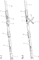
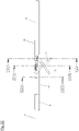
- the automatically lowerable door seal according to the invention shown in the figures has a holding means 2 which has a housing 20 .
- This can be fastened in a groove of a door, for example, by means of fastening brackets 1 . Fastening to an outside of a door is also possible with other fastening means.
- the housing 20 has a uniform profile extending in a longitudinal direction.
- the housing is preferably an aluminum extruded profile.
- a lowering mechanism 4 is fixed to the housing 20 via guide parts 21,22,23. With this lowering mechanism 4, a sealing strip 5 can be moved from a raised position to a lowered position.
- the sealing strip 5 is in two parts and includes an inner rail 50 and a sealing profile 51, which can be tightly attached to a surface, for example the floor.
- the lowering mechanism 4 is coupled to a trigger 3 via which a force necessary for actuating the seal can be introduced into the lowering mechanism 4 .
- the trigger 3 of the seal according to the invention is constructed in two parts. It has a head 31 and a coupling element 32 .
- the relative position of head 31 and coupling element 32 to each other can be changed. This makes it possible to adjust the length of the trigger in the longitudinal direction.
- a length adjustment of an actuator can be used to adjust the stroke of a seal.
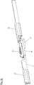
- the head 31 of the trigger 3 has a stop surface 310 via which an external force can be introduced into the trigger 3 or the lowering mechanism 4 .
- the head 31 has a support body 311 on which the stop surface 310 is provided is.
- a guide structure 312 is provided on an upper side of the support body 311 . This is formed by two laterally overhanging webs that are slidably arranged in complementary guide structures of the outer profile.
- the head also has a threaded rod 313 which is connected to the support body 311 on a side facing away from the stop surface 310 . The threaded rod 313 is used to connect the head 31 to the coupling element 32 of the trigger 3.
- the coupling element 32 of the trigger 3 also has a supporting body, namely the supporting body 320 .
- This supporting body 320 initially carries guide structures 321 which are designed exactly like the guide structures 312 of the head 31 .
- the coupling element 32 is forked on a side facing the head 31 .
- the fork legs 322, 323 thus formed delimit a receptacle 324 in which the threaded rod 313 of the head 31 is at least partially received.
- the facing inner sides of the fork legs 322, 323 are concave.
- On the inside thread sections are provided, in which the threaded rod 313 is screwed.
- the thread sections form an incomplete thread which is open on the sides.
- the threaded rod 313 is retained in this incomplete thread by the thread portions on the insides of the fork legs 322, 323 in the longitudinal direction of the seal. In the transverse direction, the threaded rod 313 is held by the concavity of the thread portions. Unlike a complete thread, which can absorb lateral forces very well, the incomplete thread can only absorb small lateral forces. However, due to the fact that the guide structures 312 and 321 are provided both on the head 31 and on the coupling element 32, and due to the fact that the head 31 and the coupling element 32 are fixed in the transverse direction of the seal, transverse forces that lead to this hardly occur could that the threaded rod 313 slips out of the incomplete thread formed by the fork legs 322, 323.
- the rod 313 could be serrated.
- the insides of the fork legs 322, 323 could be serrated so that the rod 313 can be snapped between the fork legs.
- a connecting structure 325 is provided, which serves to connect the trigger to the lowering mechanism 4 .
- the guide parts 21, 22, 23 are molded parts which have an outer contour adapted to the housing 20, so that the guide parts 21, 22, 23 can be pushed into the housing 20 and fastened there.
- the housing 20 has inwardly projecting webs 200, which are engaged behind by complementary connecting structures of the guide parts 21, 22, 23 as well as by the guide structures 312, 321 of the head 3.
- First guide parts 21 and second guide parts 22 of the guide parts 21, 22, 23 have a channel through which a rod 40 is passed.
- This rod is in several parts and has several sections lying one behind the other, which are connected to one another.
- One of these sections is a sliding part 401 which has a special function for the lowering mechanism 4 and will be described in more detail later.
- Another portion of the rod 40 is connected to the trigger.
- This section has a connection structure 49 coupled to the connection structure 325 of the trigger 3 .
- a third guide part 23 of the guide parts 21, 22, 23 is provided at the end of the rod 40.
- This third guide part 23 has a seat into which the end of the rod 40 is inserted.
- a return spring 44 of the lowering mechanism is arranged on a mandrel 230 in the receptacle. After release of the trigger 3, this return spring 44 causes the seal to transition from the actuated to the non-actuated state.
- the restoring spring presses on the end of the rod 40 which is arranged in the receptacle of the third guide part 22 .
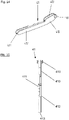
- the rod 40 is coupled to two identical scissor mechanisms comprising a first scissor element 41 and a second scissor element 42 .
- the first scissor element is mounted pivotably on the second guide part 22 via a first bearing L1.
- the second scissor element 42 is pivotably connected to an inner profile 50 of the sealing strip 5 in a second bearing L2.
- the first bearing L1 and the second bearing L2 have pivot axes lying in a plane perpendicular to the longitudinal direction of the seal.
- the first scissor element 41 and the second scissor element 42 are mounted on one another such that they can be pivoted relative to one another.
- the first, second and third bearings L1, L2, L3 are pivot bearings.
- the first scissors member 41 is bifurcated at the end supported in the first bearing L1.
- the fork legs 413 created by the fork have outwardly projecting bearing journals 410 which are mounted in recesses 220 in the second bearing part 22 .
- the trunnions 410 and the recesses 220 form the first bearing L1.
- the two fork legs 413 are spaced apart so that the rod 40 can be passed between the two fork legs.
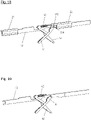
- the first scissor element 41 has a further bearing pin 411 which, together with a recess 421 which is provided in the second scissor element 42 and into which the bearing pin 411 is inserted, forms the third bearing L3.
- the first scissor element has an end 413 lying beyond the third bearing L3, viewed from the second bearing L2.
- a section 412 of the first scissor element extends between this end 413 and the third bearing L3.
- the end 413 is guided in a channel of the inner rail 50, which is delimited by side walls 501, 502 and a web 503 projecting from the side wall 502 in the direction of the first side wall 501.
- the channel forms a linear bearing in which the end 413 is guided.
- the section 412 has a slot on its side facing the rod 40 which is approximately as wide as the rod 40. In the non-actuated state of the seal, the rod 40 engages in the slot.
- the position of the first scissor element is maintained in the transverse direction by the engagement of the rod 50 in the slot and particularly by the guide in the channel.
- the second bearing L2 in which the second scissor element 42 and the inner rail 50 are journaled to one another, is formed by a journal 420 and a channel which extends through the bottom 500, the side walls 501, 502 and from the side wall 502 towards the first side wall 501 projecting web 503 is formed.
- the bearing pin 420 engages behind the web 503 .
- the second scissor element has an end 423 lying beyond the third bearing, viewed from the second bearing L2. This end 423 is connected to the rod 40 via a fourth bearing L4.
- the fourth bearing L2 is a bearing with two degrees of freedom, which permit rotation and translation of the end of the second scissor element 42 with respect to the rod 40.
- the second scissor element In the transverse direction, the second scissor element is not displaceable in either the second bearing or the fourth bearing. As a result, the second scissor element cannot be displaced, or at most only slightly, in the transverse direction.
- the end of the second scissor element 42 is prevented from shifting relative to the rod 40 by a spring 43 which pulls the end 423 of the second scissor element 42 to an edge of a recess 4011 in the sliding part 401 .
- the spring 43 is suspended at the end 423 of the second scissor element 42 and at a hook 4010 of the rod 40 . Only in special cases do the end 423 of the second scissor element and the edge of the recess 4011 detach from one another against the tension of the spring 43 .
- the end 423 of the second scissor element is displaced relative to the first bearing L1, which is firmly connected to the housing 20 via the second guide part 22.
- the second bearing L2 which connects the second scissor element 42 to the inner profile 50, is linearly lowered downwards in the third bearing due to the connection of the first and the second scissor element 41, 42.
- the sealing strip 5 is thereby lowered transversely to the longitudinal direction of the seal and pressed against the floor so that the Sealing profile 51 rests against the floor. Because two identical scissor mechanisms are provided and these are actuated synchronously by the rod 40, the sealing strip 5 is lowered parallel to the housing 2.
- the sealing strip 5 is now on the ground, it cannot be moved further down.
- the second bearing L2 can then also not be moved any further downwards, as a result of which the end 423 of the second scissor element is prevented from moving further with the rod 40. If, however, further pressure is then exerted on the rod 40 via the trigger and this pressure exceeds the force of the spring 43, the end 423 of the second scissor element 42 detaches from the edge of the recess 4011 and the end 423 moves in the recess 4011, since the rod 40 is displaced with respect to the end 423. This interaction of the recess 4011, the end 423 of the second scissor element 42 and the spring 43 prevents the lowering mechanism 4 from being overloaded, which could lead to damage to the seal.
- the end 423 of the second scissor element and a portion 422 between the end 423 and the third bearing L3 have a window through which the rod 40 is guided.
- Structures in the manner of segments of a circle are provided at the second end 423 of the second scissor element. These rest on the inside of a web 201 of the housing 20 or are arranged at only a small distance from the inside of this web 201 and move when the seal is actuated, possibly at a distance, along the inside of the housing 20.
- the trigger 3 is also designed in two parts. It has a head 31 and a coupling element 32 .
- the relative position of head 31 and coupling element 32 to each other can be changed. This makes it possible to adjust the length of the trigger in the longitudinal direction.
- a length adjustment of an actuator can be used to adjust the stroke of a seal.
- the head 31 of the trigger 3 of the variant also has a stop surface 310 via which an external force can be introduced into the trigger 3 or the lowering mechanism 4 .
- the head 31 also has a supporting body 311 on which the abutment surface 310 is provided.
- a guide structure 312 is also provided on an upper side of the support body 311 . This is in turn formed by two laterally overhanging webs which are slidably arranged in complementary guide structures of the outer profile.
- the head also has a receptacle 314 which is internally threaded.
- the coupling element 32 of the trigger 3 of the variant also has a supporting body, namely the supporting body 320 .
- This support body 320 also carries guide structures 321, which are designed exactly like the guide structures 312 of the head 31.
- the coupling element 32 has a threaded rod 326 on a side facing the head 31. This threaded rod is lateral flattened and smooth. Only a top and a bottom of the rod are rounded and have portions of the thread pitch of a conventional thread.
- the threaded rod 326 carries an incomplete thread which is screwed into the socket 314 .
- a connection structure 325 is provided on the end of the support body 320 opposite the threaded rod 326 and serves to connect the trigger to the lowering mechanism 4 .
Description
Die vorliegende Erfindung betrifft eine Dichtung mit einer absenkbaren Dichtleiste, die mittels eines durch einen Auslöser betätigbaren Absenkmechanismus absenkbar ist,
- wobei der Auslöser einen Kopf und ein Kopplungselement aufweist,
- wobei der Kopf eine Anschlagsfläche hat, mit welcher der Kopf an einer Zarge o. ä. anschlagen kann, und das Kopplungselement eine Verbindungsstruktur zur Verbindung mit dem Absenkmechanismus aufweist,
- wobei die Relativposition des Kopfs und des Kopplungselements zueinander einstellbar ist,
- wobei entweder der Kopf oder das Kopplungselement eine Gewindestange und das andere dieser beiden Elemente eine Aufnahme aufweist, in die die Gewindestange eingeschraubt ist.
- the trigger having a head and a coupling element,
- wherein the head has a stop surface with which the head can hit a frame or the like, and the coupling element has a connection structure for connection to the lowering mechanism,
- the relative position of the head and the coupling element to each other being adjustable,
- either the head or the coupling element having a threaded rod and the other of these two elements having a socket into which the threaded rod is screwed.
Eine derartige Dichtung ist aus den Dokumenten
Die bisher bekannten Dichtungen haben meist eine minimale Breite des Haltemittels von ca. 12 mm. Es gibt nur wenige Dichtungen, die eine geringere Breite, zum Beispiel von 8 mm haben. In vielen Anwendungsfällen sind aber Dichtungen erforderlich, die eine geringere Breiten haben, zum Beispiel nur eine Breite von 8 mm. Es gibt einen Bedarf an verschiedenen Modellen von schmalen Dichtungen.The previously known seals usually have a minimum width of the holding means of about 12 mm. There are only a few seals that have a smaller width, for example 8 mm. In many applications, however, seals are required that have a smaller width, for example only a width of 8 mm. There is a need for different models of narrow seals.
Hier setzt die vorliegende Erfindung an.This is where the present invention comes in.
Der Erfindung liegt die Aufgabe zugrunde, automatische Dichtungenvorzuschlagen, die eine geringe Breite haben.The object of the invention is to propose automatic seals that are narrow in width.
Dieses Problem wird durch die Gruppe der Erfindungen gelöst. Jede Erfindung leistet dabei einen Beitrag für eine schmale Dichtung, mit zum Beispiel eine Breite von nur 8 mm.This problem is solved by the group of inventions. Each invention contributes to a narrow seal, for example with a width of only 8 mm.
Einen Beitrag leistet dabei die Erfindung nach Anspruch 1, nach der
- die Aufnahme an dem Kopplungselement und die Gewindestange an dem Kopf vorgesehen ist und das Kopplungselement an einer Seite gegabelt ist und ein erstes und ein zweites Gabelbein aufweist, zwischen denen die Aufnahme gebildet ist; oder
- die Aufnahme an dem Kopf vorgesehen ist und die Gewindestange an dem Kopplungselement vorgesehen ist, die Gewindestange seitlich abgeflacht und glatt ist und lediglich eine Oberseite und eine Unterseite der Gewindestange abgerundet sind und Abschnitte eines Gewindegangs eines Gewindes aufweisen.
- the socket is provided on the coupler and the threaded rod is provided on the head and the coupler is bifurcated on one side and has first and second wishbones between which the socket is formed; or
- the receptacle is provided on the head and the threaded rod is provided on the coupling element, the threaded rod is laterally flattened and smooth and only a top and a bottom of the threaded rod are rounded and have sections of a thread pitch of a thread.
Bisher sind Auslöser so gestaltet, dass sie eine Aufnahme aufweisen, in welche eine Stange oder ähnliches eingesteckt ist. Die in die Aufnahme aufgenommene Stange gibt die Größe der Aufnahme vor. Damit eine belastbare Verbindung zwischen dem Auslöser und der Stange hergestellt werden kann, ist der Auslöser im Bereich der Aufnahme hinreichend belastbar ausgebildet, damit bei der Übertragung der Kräfte vom Auslöser auf die Stange keine Schäden am Auslöser entstehen. Die Wandungen des Auslösers, die die Aufnahme begrenzen, haben daher bisher eine gewisse Stärke, was dazu führt, dass der Auslöser eine gewisse Breite hat. Der Auslöser gibt dadurch ein Mindestmaß für die Breite der Dichtung vor.Until now, triggers have been designed in such a way that they have a receptacle into which a rod or the like is inserted. The rod received in the receptacle dictates the size of the receptacle. So that a loadable connection can be made between the trigger and the rod, the trigger is designed to be sufficiently resilient in the area of the receptacle so that the trigger is not damaged when the forces are transmitted from the trigger to the rod. The walls of the trigger that limit the shot have therefore hitherto had a certain thickness, which means that the trigger has a certain width. The trigger thereby specifies a minimum dimension for the width of the seal.
Die Aufnahme wird im ersten Fall durch das erste und das zweite Gabelbein gebildet. Die Gabelbeine können über und unter der Gewindestange angeordnet sein. Seitliche Wandungen hat die Aufnahme dann nicht. Dadurch ist eine schmale Gestaltung des Kopplungselementes möglich.In the first case, the receptacle is formed by the first and the second fork leg. The fork legs can be placed above and below the threaded rod. The recording then has no lateral walls. This allows a narrow configuration of the coupling element.
Die Gewindestange trägt im zweiten Fall ein unvollständiges Gewinde, das in die Aufnahme des Kopfes eingeschraubt ist. Auch dadurch ist eine schmale Gestaltung des Kopplungselementes möglich.In the second case, the threaded rod carries an incomplete thread, which is screwed into the seat of the head. A narrow design of the coupling element is also possible as a result.
Es hat sich gezeigt, dass trotz der fehlenden seitlichen Wandungen der Aufnahme eine belastbare Verbindung zwischen dem Kopf und dem Kopplungselement des Auslösers hergestellt werden kann.It has been shown that despite the lack of lateral walls of the receptacle, a resilient connection can be made between the head and the coupling element of the trigger.
Vorteilhaft weisen sowohl der Kopf als auch das Kopplungselement des Auslösers Führungsstrukturen auf, mit denen es möglich ist, den Kopf und den Auslöser an dem Haltemittel der Dichtung in der Betätigungsrichtung des Auslösers zu führen. Damit ist verhindert, dass der Kopf oder das Kopplungselement bei einer Betätigung seitlich ausweichen oder der Auslöser an der Verbindungsstelle zwischen dem Kopf und dem Auslöser einknickt. Kräfte und Momente, die nicht in der Betätigungsrichtung wirken, können dadurch in das Haltemittel abgeleitet werden. Über die Verbindung zwischen dem Kopf und dem Kopplungselement muss nur die in Betätigungsrichtung übertragen werden.Advantageously, both the head and the coupling element of the trigger have guide structures with which it is possible to guide the head and the trigger on the holding means of the seal in the direction of actuation of the trigger. This prevents the head or the coupling element from deflecting sideways when it is actuated, or the trigger from buckling at the connection point between the head and the trigger. Forces and moments that do not act in the direction of actuation can be diverted into the holding means. Only the direction of actuation has to be transmitted via the connection between the head and the coupling element.
Auch bei den Scherenelementen einer vorstehend beschriebenen Dichtung und insbesondere der Verbindung zwischen den beiden Scherenelementen im dritten Lager, besteht die Anforderung, dass ein seitliches Ausweichen oder Einknicken vermieden werden muss oder dass sich aufgrund von Momenten oder Kräften, die quer zur Längsrichtung der Dichtung wirken, die Verbindung des ersten und des zweiten Scherenelementes im dritten Lager löst.Even with the scissor elements of a seal described above and in particular the connection between the two scissor elements in the third camp, there is a requirement that lateral deflection or buckling must be avoided or that due to moments or forces transverse to the Act longitudinally of the seal, which solves the connection of the first and second scissor element in the third bearing.
Weitere Merkmale und Vorteile der vorliegenden Erfindung werden deutlich anhand der nachfolgenden Beschreibung einer erfindungsgemäßen Dichtung unter Bezugnahme auf die beiliegenden Abbildungen. Darin zeigen:
- Fig. 1
- eine perspektivische Ansicht der Dichtung im nicht betätigten Zustand,
- Fig. 2
- eine perspektivische Ansicht der Dichtung im betätigten Zustand,
- Fig. 3
- eine perspektivische Ansicht von Führungsteilen, des Auslösers und des Absenkmechanismus im nicht betätigten Zustand der Dichtung,
- Fig. 3a
- eine perspektivische Ansicht von Führungsteilen, des Auslösers und des Absenkmechanismus im nicht betätigten Zustand einer Variante der Dichtung,
- Fig. 4
- eine perspektivische Ansicht von Führungsteilen, des Auslösers und des Absenkmechanismus im betätigten Zustand der Dichtung,
- Fig. 4a
- eine perspektivische Ansicht von Führungsteilen, des Auslösers und des Absenkmechanismus im betätigten Zustand der Variante der Dichtung,
- Fig. 5
- einen vergrößerten Ausschnitt aus
Fig. 3 , - Fig. 5a
- einen vergrößerten Ausschnitt aus
Fig. 3a , - Fig. 6
- einen vergrößerten Ausschnitt aus
Fig. 4 , - Fig. 6a
- einen vergrößerten Ausschnitt aus
Fig. 4a , - Fig. 7
- den Auslöser der Dichtung in perspektivischer Darstellung,
- Fig. 7a
- den Auslöser der Variante der Dichtung in perspektivischer Darstellung,
- Fig. 8
- einen Kopf des Auslösers aus
Fig. 7 in perspektivischer Darstellung, - Fig. 8a
- einen Kopf des Auslösers aus
Fig. 7a in perspektivischer Darstellung, - Fig. 9
- ein Kopplungselement des Auslösers aus
Fig. 7 in perspektivischer Darstellung, - Fig. 9a
- ein Kopplungselement des Auslösers aus
Fig. 7a in perspektivischer Darstellung, - Fig. 10
- einen Schnitt durch den Auslöser aus
Fig. 7 , - Fig. 10a
- einen Schnitt durch den Auslöser aus
Fig. 7a , - Fig. 11
- eine perspektivische Ansicht von Führungsteilen und Teilen des Absenkmechanismus im nicht betätigten Zustand der Dichtung,
- Fig. 12
- die Ansicht gemäß
Fig. 11 , jedoch ohne Führungsteile, - Fig. 13
- eine perspektivische Ansicht eines Verschiebeteils des Absenkmechanismus,
- Fig. 14
- eine perspektivische Ansicht eines ersten Scherenelementes des Absenkmechanismus,
- Fig. 15
- eine Draufsicht auf das erste Scherenelement,
- Fig. 16
- eine perspektivische Ansicht eines zweiten Scherenelementes des Absenkmechanismus,
- Fig. 17
- eine Draufsicht auf das zweite Scherenelement,
- Fig. 18
- eine perspektivische Ansicht von Führungsteilen und Teilen des Absenkmechanismus im betätigten Zustand der Dichtung,
- Fig. 19
- die Ansicht gemäß
Fig. 18 , jedoch ohne Führungsteile, - Fig. 20
- eine perspektivische Ansicht von Elementen zur Rückstellung einer betätigten Dichtung,
- Fig. 21
- ein Führungselement, welches eine Rückstellfeder aufnimmt,
- Fig. 22
- eine Seitenansicht eines Teils der Dichtung,
- Fig. 23
- einen Schnitt durch den in
Fig. 22 dargestellten Teil der Dichtung gemäß der Linie XXIII-XXIII inFig. 22 , - Fig. 24
- einen Schnitt durch den in
Fig. 22 dargestellten Teil der Dichtung gemäß der Linie XXIV-XXIV inFig. 22 und - Fig. 25
- einen Schnitt durch den in
Fig. 22 dargestellten Teil der Dichtung gemäß der Linie XXV-XXV inFig. 22 .
- 1
- a perspective view of the seal in the non-actuated state,
- 2
- a perspective view of the seal in the actuated state,
- 3
- a perspective view of guide parts, the trigger and the lowering mechanism in the non-actuated state of the seal,
- Figure 3a
- a perspective view of guide parts, the trigger and the lowering mechanism in the non-actuated state of a variant of the seal,
- 4
- a perspective view of guide parts, the trigger and the lowering mechanism in the actuated state of the seal,
- Figure 4a
- a perspective view of guide parts, the trigger and the lowering mechanism in the actuated state of the variant of the seal,
- figure 5
- an
enlarged section 3 , - Figure 5a
- an enlarged section
Figure 3a , - 6
- an enlarged section
4 , - Figure 6a
- an enlarged section
Figure 4a , - 7
- the trigger of the seal in a perspective view,
- Figure 7a
- the trigger of the variant of the seal in a perspective view,
- 8
- a head of the trigger off
7 in perspective view, - Figure 8a
- a head of the trigger off
Figure 7a in perspective view, - 9
- a coupling element of the trigger
7 in perspective view, - Figure 9a
- a coupling element of the trigger
Figure 7a in perspective view, - 10
- a cut through the trigger
7 , - Figure 10a
- a cut through the trigger
Figure 7a , - 11
- a perspective view of guide parts and parts of the lowering mechanism in the non-actuated state of the seal,
- 12
- according to the view
11 , but without guide parts, - 13
- a perspective view of a sliding part of the lowering mechanism,
- 14
- a perspective view of a first scissor element of the lowering mechanism,
- 15
- a top view of the first scissor element,
- 16
- a perspective view of a second scissor element of the lowering mechanism,
- 17
- a plan view of the second scissor element,
- 18
- a perspective view of guide parts and parts of the lowering mechanism in the actuated state of the seal,
- 19
- according to the view
18 , but without guide parts, - 20
- a perspective view of elements for restoring an actuated seal,
- 21
- a guide element which accommodates a return spring,
- 22
- a side view of part of the seal,
- 23
- a cut through the in
22 illustrated part of the seal according to the line XXIII-XXIII in22 , - 24
- a cut through the in
22 illustrated part of the seal according to the line XXIV-XXIV in22 and - 25
- a cut through the in
22 illustrated part of the seal according to the line XXV-XXV in22 .
Die in den Figuren dargestellte erfindungsgemäße automatisch absenkbare Türdichtung weist ein Haltemittel 2 auf, das ein Gehäuse 20 aufweist. Dieses kann mittels Befestigungswinkeln 1 zum Beispiel in einer Nut einer Tür befestigt werden. Mit anderen Befestigungsmitteln ist auch eine Befestigung an einer Außenseite einer Tür möglich. Das Gehäuse 20 hat ein sich in einer Längsrichtung erstreckendes gleichförmiges Profil. Vorzugsweise ist das Gehäuse ein Aluminiumsstrangpressprofil.The automatically lowerable door seal according to the invention shown in the figures has a holding means 2 which has a housing 20 . This can be fastened in a groove of a door, for example, by means of fastening brackets 1 . Fastening to an outside of a door is also possible with other fastening means. The housing 20 has a uniform profile extending in a longitudinal direction. The housing is preferably an aluminum extruded profile.
In dem Gehäuse 20 ist über Führungsteile 21, 22, 23 ein Absenkmechanismus 4 an dem Gehäuse 20 befestigt. Mit diesem Absenkmechanismus 4 kann eine Dichtleiste 5 aus einer angehobenen Position in eine abgesenkte Position bewegt werden. Die Dichtleiste 5 ist zweiteilig und umfasst eine Innenschiene 50 und ein Dichtungsprofil 51, welche sich dicht sind an einer Oberfläche, zum Beispiel dem Fußboden, anlegen kann.In the housing 20, a lowering mechanism 4 is fixed to the housing 20 via
Der Absenkmechanismus 4 ist mit einem Auslöser 3 gekoppelt, über den eine für die Betätigung der Dichtung notwendige Kraft in den Absenkmechanismus 4 eingebracht werden kann.The lowering mechanism 4 is coupled to a
Der Auslöser 3 der erfindungsgemäßen Dichtung ist zweiteilig aufgebaut. Er weist einen Kopf 31 und ein Kopplungselements 32 auf. Die Relativposition von Kopf 31 und Kopplungselement 32 zu einander kann verändert werden. Dadurch ist es möglich die Länge des Auslösers in Längsrichtung einzustellen. Eine Längeneinstellung eines Auslösers kann genutzt werden, um den Hub einer Dichtung einzustellen.The
Der Kopf 31 des Auslösers 3 weist eine Anschlagsfläche 310 auf, über die eine äußere Kraft in den Auslöser 3 bzw. den Absenkmechanismus 4 eingeleitet werden kann. Der Kopf 31 hat einen Tragkörper 311, an dem die Anschlagsfläche 310 vorgesehen ist. An einer Oberseite des Tragkörper 311 ist eine Führungsstruktur 312 vorgesehen. Diese wird durch zwei seitlich auskragende Stege gebildet, die in komplementären Führungsstrukturen des Außenprofil verschiebbar angeordnet sind. Der Kopf weist außerdem eine Gewindestange 313 auf, die sich an den Tragkörper 311 an einer der Anschlagsfläche 310 abgewandten Seite anschließt. Die Gewindestange 313 dient der Verbindung des Kopfes 31 mit dem Kopplungselement 32 des Auslösers 3.The
Das Kopplungselement 32 des Auslösers 3 weißt ebenfalls einen Tragkörper, nämlich den Tragkörper 320 auf. Dieser Tragkörper 320 trägt zunächst Führungsstrukturen 321, die genau so gestaltet sind wie die Führungsstrukturen 312 Kopfes 31. Das Kopplungselement 32 ist auf einer dem Kopf 31 zugewandten Seite gegabelt. Die dadurch gebildeten Gabelbeine 322, 323 begrenzen einer Aufnahme 324, in welcher die Gewindestange 313 des Kopfes 31 zumindest teilweise aufgenommen ist. Die einander zugewandten Innenseiten der Gabelbeine 322, 323 sind konkav gewölbt. Auf den Innenseiten sind Gewindegangabschnitte vorgesehen, in die die Gewindestange 313 eingeschraubt ist. Die Gewindegangabschnitte bilden ein unvollständiges Gewinde, welches an den Seiten offen ist. Die Gewindestange 313 wird in diesem unvollständigen Gewinde durch die Gewindegangabschnitte auf den Innenseiten der Gabelbeine 322, 323 in der Längsrichtung der Dichtung gehalten. In der Querrichtung wird die Gewindestange 313 durch die konkave Wölbung der Gewindegangabschnitte gehalten. Anders als bei einem vollständigen Gewinde, welches Querkräfte sehr gut aufnehmen kann, kann das unvollständige Gewinde nur geringe Querkräfte aufnehmen. Dadurch allerdings, dass sowohl am Kopf 31 als auch am Kopplungselement 32 die Führungsstrukturen 312 bzw. 321 vorgesehen sind, und dadurch, dass der Kopf 31 und das Kopplungselement 32 in der Querrichtung der Dichtung fixiert sind, treten kaum Querkräfte auf, die dazu führen könnten, dass die Gewindestange 313 aus dem durch die Gabelbeine 322, 323 gebildeten unvollständigen Gewinde herausrutscht.The
Anstelle des Gewindes könnte die Stange 313 gezahnt sein. Entsprechend könnten die Innenseiten der Gabelbeine 322, 323 gezahnt sein, so dass die Stange 313 zwischen den Gabelbeinen eingerastet werden kann.Instead of being threaded, the
An dem der Gabeln entgegengesetzten Ende des Tragkörper ist eine Verbindungsstruktur 325 vorgesehen, die der Verbindung des Auslösers mit dem Absenkmechanismus 4 dient.At the end of the supporting body opposite the forks, a connecting
Bei den Führungsteilen 21, 22, 23 handelt es sich um Formteile, die eine an das Gehäuse 20 angepasste Außenkontur haben, so dass die Führungsteile 21, 22, 23 in das Gehäuse 20 eingeschoben und dort befestigt werden können. Das Gehäuse 20 weißt dazu nach innen ragenden Stege 200 auf, die von komplementären Verbindungstrukturen der Führungsteile 21, 22, 23 ebenso hintergriffen werden wie von den Führungsstrukturen 312, 321 des Kopfes 3.The
Erste Führungsteile 21 und zweite Führungsteile 22 der Führungsteile 21, 22, 23 weisen einen Kanal auf, durch den eine Stange 40 hindurchgeführt ist. Diese Stange ist mehrteilige und weist mehrere hintereinander liegende Abschnitte auf, die miteinander verbunden sind. Einer dieser Abschnitte ist ein Verschiebeteil 401 welches eine besondere Funktion für den Absenkmechanismus 4 hat und noch näher beschrieben wird. Ein anderer Abschnitt der Stange 40 ist mit dem Auslöser verbunden. Dieser Abschnitt weist eine Verbindungsstruktur 49 auf, die mit der Verbindungsstruktur 325 des Auslösers 3 gekoppelt ist.First guide
Ein drittes Führungsteile 23 der Führungsteile 21, 22, 23 ist am Ende der Stange 40 vorgesehen. Dieses dritte Führungsteile 23 hat eine Aufnahme, in die das Ende der Stange 40 eingeführt ist. In der Aufnahme ist auf einem Dorn 230 eine Rückstellfeder 44 des Absenkmechanismus angeordnet. Diese Rückstellfeder 44 bewirkt nach einer Entlastung des Auslösers 3 einen Übergang der Dichtung vom betätigten in den nicht betätigten Zustand. Die Rückstellfeder drückt dazu auf das Ende der Stange 40, welches in der Aufnahme des dritten Führungsteile 22 angeordnet ist.A
Die Stange 40 ist mit zwei identischen Scherenmechanismen gekoppelt, die ein erstes Scherenelement 41 und ein zweites Scherenelement 42 umfassen. Das erste Scherenelement ist über ein erstes Lager L1 schwenkbar an dem zweiten Führungsteil 22 gelagert. Das zweite Scherenelement 42 ist in einem zweiten Lager L2 schwenkbar mit einem Innenprofil 50 der Dichtleiste 5 verbunden. Das erste Lager L1 und das zweite Lager L2 haben Schwenkachsen, die in einer Ebene senkrecht zur Längsrichtung der Dichtung liegen. In einem dritten Lager L3 sind das erste Scherenelement 41 und das zweite Scherenelement 42 zueinander schwenkbar aneinandergelagert. Das erste, zweite und dritte Lager L1, L2, L3 sind Drehlager.The
Das erste Scherenelement 41 ist am im ersten Lager L1 gelagerten Ende gegabelt. Die durch die Gabelung entstandenen Gabelbeine 413 weisen nach außen ragende Lagerzapfen 410 auf, die in Ausnehmungen 220 in dem zweiten Lagerteil 22 gelagert sind. Die Zapfen 410 und die Ausnehmungen 220 bilden das erste Lager L1. Die beiden Gabelbeine 413 haben einen Abstand, der so gewählt ist, dass die Stange 40 zwischen den beiden Gabelbeinen hindurchgeführt werden kann.The
Das erste Scherenelement 41 hat einen weiteren Lagerzapfen 411 der zusammen mit einer Ausnehmung 421, die in dem zweiten Scherenelement 42 vorgesehen ist und in die der Lagerzapfen 411 eingesteckt ist, das dritte Lager L3 bildet.The
Das erste Scherenelement hat ein vom zweiten Lager L2 betrachtet jenseits des dritten Lagers L3 liegendes Ende 413. Zwischen diesem Ende 413 und dem dritten Lager L3 erstreckt sich ein Abschnitt 412 des ersten Scherenelementes. Das Ende 413 wird in einem Kanal der Innenschiene 50 geführt, die durch Seitenwände 501, 502 und einen von der Seitenwand 502 in Richtung zur ersten Seitenwand 501 ragenden Steg 503 begrenzt wird. Der Kanal bildet ein Linearlager, in dem das Ende 413 geführt ist. Der Abschnitt 412 weist auf seiner der Stange 40 zugewandten Seite einen Schlitz auf, der ungefähr so breit ist wie die Stange 40. Im nicht betätigten Zustand der Dichtung greift die Stange 40 in den Schlitz ein. Die Lage des ersten Scherenelementes wird durch das Eingreifen der Stange 50 in den Schlitz und insbesondere durch die Führung in dem Kanal in der Querrichtung gehalten.The first scissor element has an
Das zweite Lager L2, in dem das zweite Scherenelement 42 und die Innenschiene 50 an einander gelagert sind, wird durch einen Lagerzapfen 420 und einen Kanal gebildet, der durch den Boden 500, die Seitenwände 501, 502 und den von der Seitenwand 502 in Richtung zur ersten Seitenwand 501 ragenden Steg 503 gebildet ist. Der Steg 503 wird von dem Lagerzapfen 420 hintergriffen.The second bearing L2, in which the
Das zweite Scherenelement hat ein vom zweiten Lager L2 betrachtet jenseits des dritten Lagers liegendes Ende 423. Dieses Ende 423 ist über ein viertes Lager L4 mit der Stange 40 verbunden. Es handelt sich bei dem vierten Lager L2 um ein Lager mit zwei Freiheitgeraden, die eine Drehung und eine Verschiebung des Endes des zweite Scherenelementes 42 gegenüber der Stange 40 zulassen.The second scissor element has an end 423 lying beyond the third bearing, viewed from the second bearing L2. This end 423 is connected to the
In der Querrichtung ist das zweite Scherenelement weder im zweiten Lager noch im vierten Lager verschiebbar. Dadurch kann das zweiten Scherenelement nicht oder allenfalls wenig in der Querrichtung verschoben werden.In the transverse direction, the second scissor element is not displaceable in either the second bearing or the fourth bearing. As a result, the second scissor element cannot be displaced, or at most only slightly, in the transverse direction.
Dadurch das weder das erste Scherenelement 41 noch das zweite Scherenelement 42 in der Querrichtung in einem bedeutenden Maß verschoben werden können, kann sich der Lagerzapfen 411 nicht aus der Ausnehmung 421 lösen.Due to the fact that neither the
Im Normalfall ist das Ende des zweiten Scherenelementes 42 an einer Verschiebung gegenüber der Stange 40 durch eine Feder 43 gehindert, die das Ende 423 des zweiten Scherenelementes 42 in an einen Rand einer Ausnehmung 4011 des Verschiebeteils 401 zieht. Die Feder 43 ist dazu an dem Ende 423 des zweiten Scherenelementes 42 und an einem Haken 4010 der Stange 40 eingehängt. Nur in besonderen Fällen lösen sich das Ende 423 des zweiten Scherenelementes und Rand der Ausnehmung 4011 gegen den Zug der Feder 43 voneinander.Normally, the end of the
Wird nun durch eine Betätigung des Auslösers 3 die Stange 40 verschoben, verschiebt sich das Ende 423 des zweiten Scherenelementes gegenüber dem über das zweite Führungsteil 22 fest mit dem Gehäuse 20 verbundenen ersten Lager L1. Dabei wird das zweite Lager L2, dass das zweite Scherenelement 42 mit dem Innenprofil 50 verbindet, aufgrund der Verbindung des ersten und des zweiten Scherenelementes 41, 42 im dritten Lager linear nach unten abgesenkt. Die Dichtleiste 5 wird dadurch quer zur Längsrichtung der Dichtung abgesenkt und gegen den Boden gedrückt, so dass das Dichtungsprofil 51 an dem Boden anliegt. Dadurch, dass zwei identische Scherenmechanismen vorgesehen sind und diese durch die Stange 40 synchron betätigt werden, wird die Dichtleiste 5 parallel zum Gehäuse 2 abgesenkt.If the
Liegt nun die Dichtleiste 5 auf dem Boden auf, kann sie nicht weiter nach unten bewegt werden. Auch das zweite Lager L2 kann dann nicht weiter nach unten bewegt werden, wodurch das Ende 423 des zweiten Scherenelementes an einer weiteren Bewegung mit der Stange 40 gehindert ist. Wird dann aber weiter über den Auslöser ein Druck auf die Stange 40 ausgeübt und übersteigt dieser Druck die Kraft der Feder 43, löst sich das Ende 423 des zweiten Scherenelementes 42 von dem Rand der Ausnehmung 4011 und das Ende 423 bewegt sich in der Ausnehmung 4011, da die Stange 40 gegenüber dem Ende 423 verschoben wird. Durch dieses Zusammenwirken der Ausnehmung 4011, des Endes 423 des zweiten Scherenelementes 42 und der Feder 43 wird eine Überlastung des Absenkmechanismus 4 verhindert, die zu Schäden an der Dichtung führen könnte.If the sealing strip 5 is now on the ground, it cannot be moved further down. The second bearing L2 can then also not be moved any further downwards, as a result of which the end 423 of the second scissor element is prevented from moving further with the
Das Ende 423 des zweiten Scherenelementes und ein Abschnitt 422 zwischen dem Ende 423 und dem dritten Lager L3 weisen ein Fenster auf, durch das die Stange 40 geführt ist.The end 423 of the second scissor element and a
An dem zweiten Ende 423 des zweiten Scherenelementes sind kreissegmentartige Strukturen vorgesehen. Diese liegen an der Innenseite eines Stegs 201 des Gehäuses 20 an oder sind mit nur geringem Abstand zur Innenseite dieses Stegs 201 angeordnet und bewegen sich bei einer Betätigung der Dichtung, ggf. mit Abstand, entlang der Innenseite des Gehäuses 20.Structures in the manner of segments of a circle are provided at the second end 423 of the second scissor element. These rest on the inside of a web 201 of the housing 20 or are arranged at only a small distance from the inside of this web 201 and move when the seal is actuated, possibly at a distance, along the inside of the housing 20.
Die in den
Bei der Variante ist der Auslöser 3 ebenfalls zweiteilig gestaltet Er weist einen Kopf 31 und ein Kopplungselements 32 auf. Die Relativposition von Kopf 31 und Kopplungselement 32 zu einander kann verändert werden. Dadurch ist es möglich die Länge des Auslösers in Längsrichtung einzustellen. Eine Längeneinstellung eines Auslösers kann genutzt werden, um den Hub einer Dichtung einzustellen.In the variant, the
Der Kopf 31 des Auslösers 3 der Variante weist ebenfalls eine Anschlagsfläche 310 auf, über die eine äußere Kraft in den Auslöser 3 bzw. den Absenkmechanismus 4 eingeleitet werden kann. Der Kopf 31 hat auch einen Tragkörper 311, an dem die Anschlagsfläche 310 vorgesehen ist. An einer Oberseite des Tragkörper 311 ist ebenfalls eine Führungsstruktur 312 vorgesehen. Diese wird wiederum durch zwei seitlich auskragende Stege gebildet, die in komplementären Führungsstrukturen des Außenprofil verschiebbar angeordnet sind. Der Kopf weist außerdem eine Aufnahme 314 auf, die ein Innengewinde hat.The
Das Kopplungselement 32 des Auslösers 3 der Variante weißt ebenfalls einen Tragkörper, nämlich den Tragkörper 320 auf. Dieser Tragkörper 320 trägt ebenfalls Führungsstrukturen 321, die genau so gestaltet sind wie die Führungsstrukturen 312 Kopfes 31. Das Kopplungselement 32 weist auf einer dem Kopf 31 zugewandten Seite eine Gewindestange 326 auf. Diese Gewindestange ist seitlich abgeflacht und glatt. Lediglich eine Oberseite und eine Unterseite der Stange sind abgerundet und weisen Abschnitte des Gewindegangs eines herkömmlichen Gewindes auf. Die Gewindestange 326 trägt ein unvollständiges Gewinde, das in die Aufnahme 314 eingeschraubt ist.The
An dem der Gewindestange 326 entgegengesetzten Ende des Tragkörper 320 ist eine Verbindungsstruktur 325 vorgesehen, die der Verbindung des Auslösers mit dem Absenkmechanismus 4 dient.A
Claims (4)
- Seal (D) with a lowerable sealing strip (5) which can be lowered by means of a lowering mechanism (4) which can be actuated by a trigger (3),- wherein the trigger (3) has a head (31) and a coupling element (32),- wherein the head (31) has an abutment surface (310) with which the head (31) can abut against a frame or the like, and the coupling element (32) has a connection structure (325) for connection to the lowering mechanism (4),- wherein the relative position of the head (31) and the coupling element (32) to one another is adjustable,- wherein either the head (31) or the coupling element (32) has a threaded rod (313, 326) and the other of these two elements has a receptacle (314, 324) into which the threaded rod (313, 326) is screwed,characterised in that- the receptacle (324) is provided on the coupling element (32) and the threaded rod (313) is provided on the head (31), and in that the coupling element (32) is forked on one side and has a first and a second fork leg (322, 323) between which the receptacle (324) is formed; or- in that the receptacle (314) is provided on the head (31) and the threaded rod (326) is provided on the coupling element (32), in that the threaded rod (326) is laterally flattened and smooth, and in that only an upper surface and a lower surface of the threaded rod (326) are rounded and have portions of a pitch of a thread.
- Seal (D) according to claim 1, characterised in that facing sides of the fork legs (322, 323) are concavely curved if the receptacle (324) is provided on the coupling element (32) and the threaded rod (313) is provided on the head (31) and the coupling element (32) is forked on one side and has a first and a second fork leg (322, 323) between which the receptacle (324) is formed.
- Seal (D) according to claim 2, characterised in that the facing sides of the fork legs (322, 323) have portions of at least one pitch into which the threaded rod (313) of the trigger (3) is screwed.
- Seal (D) according to any of claims 1 to 3, characterised in that both the head (31) and the coupling element (32) of the trigger have guide structures (312, 321) by means of which it is possible to guide the head (31) and the trigger (3) on the retaining means (2) of the seal (D) in the actuating direction of the trigger (3).
Priority Applications (3)
| Application Number | Priority Date | Filing Date | Title |
|---|---|---|---|
| EP22181870.1A EP4105432A1 (en) | 2019-02-20 | 2019-03-29 | Automatic seal with a guiding means for guiding a push rod and method for positioning the guiding means in a housing of the seal |
| EP19216649.4A EP3699385B1 (en) | 2019-02-20 | 2019-12-16 | Automatic door seal with at least one holding means, at least one shear mechanism with two shear elements and a sealing strip |
| EP20158446.3A EP3699386B1 (en) | 2019-02-20 | 2020-02-20 | Automatic door seal with a guiding means for guiding a push rod and a method for positioning the guiding means in a housing of the seal |
Applications Claiming Priority (1)
| Application Number | Priority Date | Filing Date | Title |
|---|---|---|---|
| EP19158350 | 2019-02-20 |
Related Child Applications (2)
| Application Number | Title | Priority Date | Filing Date |
|---|---|---|---|
| EP22181870.1A Division EP4105432A1 (en) | 2019-02-20 | 2019-03-29 | Automatic seal with a guiding means for guiding a push rod and method for positioning the guiding means in a housing of the seal |
| EP22181870.1A Division-Into EP4105432A1 (en) | 2019-02-20 | 2019-03-29 | Automatic seal with a guiding means for guiding a push rod and method for positioning the guiding means in a housing of the seal |
Publications (2)
| Publication Number | Publication Date |
|---|---|
| EP3699384A1 EP3699384A1 (en) | 2020-08-26 |
| EP3699384B1 true EP3699384B1 (en) | 2022-08-17 |
Family
ID=65529424
Family Applications (5)
| Application Number | Title | Priority Date | Filing Date |
|---|---|---|---|
| EP22181870.1A Pending EP4105432A1 (en) | 2019-02-20 | 2019-03-29 | Automatic seal with a guiding means for guiding a push rod and method for positioning the guiding means in a housing of the seal |
| EP19166220.4A Active EP3699384B1 (en) | 2019-02-20 | 2019-03-29 | Seal with a lowerable sealing strip which can be lowered by means of an actuator-operated lowering mechanism |
| EP19216649.4A Active EP3699385B1 (en) | 2019-02-20 | 2019-12-16 | Automatic door seal with at least one holding means, at least one shear mechanism with two shear elements and a sealing strip |
| EP20158446.3A Active EP3699386B1 (en) | 2019-02-20 | 2020-02-20 | Automatic door seal with a guiding means for guiding a push rod and a method for positioning the guiding means in a housing of the seal |
| EP20168063.4A Active EP3868994B1 (en) | 2019-02-20 | 2020-04-03 | Seal with modules having a lowering mechanism |
Family Applications Before (1)
| Application Number | Title | Priority Date | Filing Date |
|---|---|---|---|
| EP22181870.1A Pending EP4105432A1 (en) | 2019-02-20 | 2019-03-29 | Automatic seal with a guiding means for guiding a push rod and method for positioning the guiding means in a housing of the seal |
Family Applications After (3)
| Application Number | Title | Priority Date | Filing Date |
|---|---|---|---|
| EP19216649.4A Active EP3699385B1 (en) | 2019-02-20 | 2019-12-16 | Automatic door seal with at least one holding means, at least one shear mechanism with two shear elements and a sealing strip |
| EP20158446.3A Active EP3699386B1 (en) | 2019-02-20 | 2020-02-20 | Automatic door seal with a guiding means for guiding a push rod and a method for positioning the guiding means in a housing of the seal |
| EP20168063.4A Active EP3868994B1 (en) | 2019-02-20 | 2020-04-03 | Seal with modules having a lowering mechanism |
Country Status (2)
| Country | Link |
|---|---|
| EP (5) | EP4105432A1 (en) |
| DK (1) | DK3699384T3 (en) |
Families Citing this family (2)
| Publication number | Priority date | Publication date | Assignee | Title |
|---|---|---|---|---|
| CZ2020558A3 (en) | 2020-10-13 | 2022-04-27 | René Göndör | Movable sealing strip door leaf assembly and a door leaf with this assembly |
| EP4001577A1 (en) * | 2020-11-24 | 2022-05-25 | Athmer OHG | Automatic seal with an elastomer overload spring |
Family Cites Families (8)
| Publication number | Priority date | Publication date | Assignee | Title |
|---|---|---|---|---|
| CH465830A (en) | 1967-10-03 | 1968-11-30 | Arquint Joseph | Door sealing against a threshold-free floor |
| AUPN527795A0 (en) * | 1995-09-06 | 1995-09-28 | Raven Products Pty. Ltd. | Door dropseal |
| KR200183456Y1 (en) * | 1999-12-22 | 2000-05-15 | 이강호 | An airtight-apparatus of eliminating threshold type door |
| IT1314655B1 (en) * | 2000-03-10 | 2002-12-31 | Aldo Comaglio | PERFECTED PARAFRED DEVICE FOR DOORS |
| NL1022757C2 (en) | 2003-02-21 | 2004-08-24 | Elton Bv Ind & Handel | Sealing device for a door, door provided with such a sealing device, and movement module provided with a movement mechanism for such a sealing device. |
| DE20306091U1 (en) * | 2003-04-15 | 2003-07-03 | Athmer Fa F | Door-sealing device |
| PL3284897T3 (en) | 2016-08-18 | 2022-08-01 | Athmer Ohg | Seal with a movable sealing strip and a reset and/or excess movement mechanism |
| DE202016105669U1 (en) | 2016-10-11 | 2018-01-12 | Athmer Ohg | Seal with a guided, adjustable trigger |
-
2019
- 2019-03-29 EP EP22181870.1A patent/EP4105432A1/en active Pending
- 2019-03-29 EP EP19166220.4A patent/EP3699384B1/en active Active
- 2019-03-29 DK DK19166220.4T patent/DK3699384T3/en active
- 2019-12-16 EP EP19216649.4A patent/EP3699385B1/en active Active
-
2020
- 2020-02-20 EP EP20158446.3A patent/EP3699386B1/en active Active
- 2020-04-03 EP EP20168063.4A patent/EP3868994B1/en active Active
Also Published As
| Publication number | Publication date |
|---|---|
| EP3699385A1 (en) | 2020-08-26 |
| EP3699386B1 (en) | 2022-01-05 |
| EP3868994A1 (en) | 2021-08-25 |
| EP3699384A1 (en) | 2020-08-26 |
| EP3699386A1 (en) | 2020-08-26 |
| EP3699385B1 (en) | 2022-02-09 |
| EP3868994B1 (en) | 2023-09-27 |
| EP4105432A1 (en) | 2022-12-21 |
| DK3699384T3 (en) | 2022-10-24 |
Similar Documents
| Publication | Publication Date | Title |
|---|---|---|
| EP2474698B1 (en) | Sealing device with a seal profile and a mechanism for displacing the seal profile when the mechanism is actuated | |
| EP3284898B1 (en) | Seal with a sealing strip which can be lowered by means of two scissor mechanisms | |
| WO2015018526A1 (en) | Fitting for fixing an object on a rail | |
| EP3699384B1 (en) | Seal with a lowerable sealing strip which can be lowered by means of an actuator-operated lowering mechanism | |
| EP2668869B1 (en) | Releasable locking element | |
| CH696004A5 (en) | Awning. | |
| EP1577472B1 (en) | Sliding construction element and clamping or check device for the fittings of window wings | |
| EP2233039B1 (en) | Drawer guide | |
| EP3599335B1 (en) | Lowerable seal, in particular for sliding doors | |
| DE2121211C3 (en) | Device for sealing the points of contact between two machine elements that can be moved relative to one another | |
| EP1680977B1 (en) | Braking device for a mobile furniture element | |
| EP3859119A1 (en) | Automatic seal with an overload mechanism and / or a reset mechanism with a spring with a waveform, triangle or sawtooth profile or similar profile | |
| DE8535142U1 (en) | Extending table | |
| DE4441011C1 (en) | Locking device for vehicle arm rest | |
| DE102015010990B4 (en) | Suspension or support device for vertically shifting loads, in particular pipes and the like | |
| EP2803533B1 (en) | Device for assembling a rail on a support with a longitudinal channel | |
| EP3768930B1 (en) | Sealing device | |
| AT508129B1 (en) | FASTENING DEVICE FOR A FURNITURE FITTING | |
| DE2256682C3 (en) | Device for tightly clamping the connection of a compression measuring device in an internal combustion engine | |
| DE202022102658U1 (en) | Seal, in particular for sliding doors or sliding gates | |
| EP2902563B1 (en) | Awning | |
| DE3744295A1 (en) | Clamping device for the firm clamping of a linearly movable rod | |
| EP0544030A1 (en) | Vacuum gate valve | |
| EP3704336A1 (en) | Strip part and system having a strip part and a profile | |
| EP3655610A1 (en) | Drop-down seal |
Legal Events
| Date | Code | Title | Description |
|---|---|---|---|
| PUAI | Public reference made under article 153(3) epc to a published international application that has entered the european phase |
Free format text: ORIGINAL CODE: 0009012 |
|
| STAA | Information on the status of an ep patent application or granted ep patent |
Free format text: STATUS: THE APPLICATION HAS BEEN PUBLISHED |
|
| AK | Designated contracting states |
Kind code of ref document: A1 Designated state(s): AL AT BE BG CH CY CZ DE DK EE ES FI FR GB GR HR HU IE IS IT LI LT LU LV MC MK MT NL NO PL PT RO RS SE SI SK SM TR |
|
| AX | Request for extension of the european patent |
Extension state: BA ME |
|
| STAA | Information on the status of an ep patent application or granted ep patent |
Free format text: STATUS: REQUEST FOR EXAMINATION WAS MADE |
|
| 17P | Request for examination filed |
Effective date: 20210226 |
|
| RBV | Designated contracting states (corrected) |
Designated state(s): AL AT BE BG CH CY CZ DE DK EE ES FI FR GB GR HR HU IE IS IT LI LT LU LV MC MK MT NL NO PL PT RO RS SE SI SK SM TR |
|
| GRAP | Despatch of communication of intention to grant a patent |
Free format text: ORIGINAL CODE: EPIDOSNIGR1 |
|
| STAA | Information on the status of an ep patent application or granted ep patent |
Free format text: STATUS: GRANT OF PATENT IS INTENDED |
|
| INTG | Intention to grant announced |
Effective date: 20220301 |
|
| GRAS | Grant fee paid |
Free format text: ORIGINAL CODE: EPIDOSNIGR3 |
|
| GRAA | (expected) grant |
Free format text: ORIGINAL CODE: 0009210 |
|
| STAA | Information on the status of an ep patent application or granted ep patent |
Free format text: STATUS: THE PATENT HAS BEEN GRANTED |
|
| AK | Designated contracting states |
Kind code of ref document: B1 Designated state(s): AL AT BE BG CH CY CZ DE DK EE ES FI FR GB GR HR HU IE IS IT LI LT LU LV MC MK MT NL NO PL PT RO RS SE SI SK SM TR |
|
| REG | Reference to a national code |
Ref country code: CH Ref legal event code: EP |
|
| REG | Reference to a national code |
Ref country code: DE Ref legal event code: R096 Ref document number: 502019005302 Country of ref document: DE |
|
| REG | Reference to a national code |
Ref country code: IE Ref legal event code: FG4D Free format text: LANGUAGE OF EP DOCUMENT: GERMAN |
|
| REG | Reference to a national code |
Ref country code: AT Ref legal event code: REF Ref document number: 1512298 Country of ref document: AT Kind code of ref document: T Effective date: 20220915 |
|
| REG | Reference to a national code |
Ref country code: DK Ref legal event code: T3 Effective date: 20221017 |
|
| REG | Reference to a national code |
Ref country code: SE Ref legal event code: TRGR |
|
| REG | Reference to a national code |
Ref country code: NO Ref legal event code: T2 Effective date: 20220817 |
|
| REG | Reference to a national code |
Ref country code: NL Ref legal event code: FP |
|
| REG | Reference to a national code |
Ref country code: LT Ref legal event code: MG9D |
|
| PG25 | Lapsed in a contracting state [announced via postgrant information from national office to epo] |
Ref country code: RS Free format text: LAPSE BECAUSE OF FAILURE TO SUBMIT A TRANSLATION OF THE DESCRIPTION OR TO PAY THE FEE WITHIN THE PRESCRIBED TIME-LIMIT Effective date: 20220817 Ref country code: PT Free format text: LAPSE BECAUSE OF FAILURE TO SUBMIT A TRANSLATION OF THE DESCRIPTION OR TO PAY THE FEE WITHIN THE PRESCRIBED TIME-LIMIT Effective date: 20221219 Ref country code: LV Free format text: LAPSE BECAUSE OF FAILURE TO SUBMIT A TRANSLATION OF THE DESCRIPTION OR TO PAY THE FEE WITHIN THE PRESCRIBED TIME-LIMIT Effective date: 20220817 Ref country code: LT Free format text: LAPSE BECAUSE OF FAILURE TO SUBMIT A TRANSLATION OF THE DESCRIPTION OR TO PAY THE FEE WITHIN THE PRESCRIBED TIME-LIMIT Effective date: 20220817 Ref country code: FI Free format text: LAPSE BECAUSE OF FAILURE TO SUBMIT A TRANSLATION OF THE DESCRIPTION OR TO PAY THE FEE WITHIN THE PRESCRIBED TIME-LIMIT Effective date: 20220817 |
|
| PG25 | Lapsed in a contracting state [announced via postgrant information from national office to epo] |
Ref country code: PL Free format text: LAPSE BECAUSE OF FAILURE TO SUBMIT A TRANSLATION OF THE DESCRIPTION OR TO PAY THE FEE WITHIN THE PRESCRIBED TIME-LIMIT Effective date: 20220817 Ref country code: IS Free format text: LAPSE BECAUSE OF FAILURE TO SUBMIT A TRANSLATION OF THE DESCRIPTION OR TO PAY THE FEE WITHIN THE PRESCRIBED TIME-LIMIT Effective date: 20221217 Ref country code: HR Free format text: LAPSE BECAUSE OF FAILURE TO SUBMIT A TRANSLATION OF THE DESCRIPTION OR TO PAY THE FEE WITHIN THE PRESCRIBED TIME-LIMIT Effective date: 20220817 Ref country code: GR Free format text: LAPSE BECAUSE OF FAILURE TO SUBMIT A TRANSLATION OF THE DESCRIPTION OR TO PAY THE FEE WITHIN THE PRESCRIBED TIME-LIMIT Effective date: 20221118 |
|
| PG25 | Lapsed in a contracting state [announced via postgrant information from national office to epo] |
Ref country code: SM Free format text: LAPSE BECAUSE OF FAILURE TO SUBMIT A TRANSLATION OF THE DESCRIPTION OR TO PAY THE FEE WITHIN THE PRESCRIBED TIME-LIMIT Effective date: 20220817 Ref country code: RO Free format text: LAPSE BECAUSE OF FAILURE TO SUBMIT A TRANSLATION OF THE DESCRIPTION OR TO PAY THE FEE WITHIN THE PRESCRIBED TIME-LIMIT Effective date: 20220817 Ref country code: ES Free format text: LAPSE BECAUSE OF FAILURE TO SUBMIT A TRANSLATION OF THE DESCRIPTION OR TO PAY THE FEE WITHIN THE PRESCRIBED TIME-LIMIT Effective date: 20220817 Ref country code: CZ Free format text: LAPSE BECAUSE OF FAILURE TO SUBMIT A TRANSLATION OF THE DESCRIPTION OR TO PAY THE FEE WITHIN THE PRESCRIBED TIME-LIMIT Effective date: 20220817 |
|
| PGFP | Annual fee paid to national office [announced via postgrant information from national office to epo] |
Ref country code: NO Payment date: 20230324 Year of fee payment: 5 Ref country code: FR Payment date: 20230327 Year of fee payment: 5 Ref country code: DK Payment date: 20230323 Year of fee payment: 5 |
|
| REG | Reference to a national code |
Ref country code: DE Ref legal event code: R097 Ref document number: 502019005302 Country of ref document: DE |
|
| PG25 | Lapsed in a contracting state [announced via postgrant information from national office to epo] |
Ref country code: SK Free format text: LAPSE BECAUSE OF FAILURE TO SUBMIT A TRANSLATION OF THE DESCRIPTION OR TO PAY THE FEE WITHIN THE PRESCRIBED TIME-LIMIT Effective date: 20220817 Ref country code: EE Free format text: LAPSE BECAUSE OF FAILURE TO SUBMIT A TRANSLATION OF THE DESCRIPTION OR TO PAY THE FEE WITHIN THE PRESCRIBED TIME-LIMIT Effective date: 20220817 |
|
| PGFP | Annual fee paid to national office [announced via postgrant information from national office to epo] |
Ref country code: SE Payment date: 20230314 Year of fee payment: 5 Ref country code: IT Payment date: 20230322 Year of fee payment: 5 Ref country code: GB Payment date: 20230322 Year of fee payment: 5 Ref country code: DE Payment date: 20230331 Year of fee payment: 5 Ref country code: BE Payment date: 20230321 Year of fee payment: 5 |
|
| PLBE | No opposition filed within time limit |
Free format text: ORIGINAL CODE: 0009261 |
|
| STAA | Information on the status of an ep patent application or granted ep patent |
Free format text: STATUS: NO OPPOSITION FILED WITHIN TIME LIMIT |
|
| PG25 | Lapsed in a contracting state [announced via postgrant information from national office to epo] |
Ref country code: AL Free format text: LAPSE BECAUSE OF FAILURE TO SUBMIT A TRANSLATION OF THE DESCRIPTION OR TO PAY THE FEE WITHIN THE PRESCRIBED TIME-LIMIT Effective date: 20220817 |
|
| PGFP | Annual fee paid to national office [announced via postgrant information from national office to epo] |
Ref country code: NL Payment date: 20230321 Year of fee payment: 5 |
|
| 26N | No opposition filed |
Effective date: 20230519 |
|
| P01 | Opt-out of the competence of the unified patent court (upc) registered |
Effective date: 20230616 |
|
| PGFP | Annual fee paid to national office [announced via postgrant information from national office to epo] |
Ref country code: CH Payment date: 20230401 Year of fee payment: 5 |
|
| PG25 | Lapsed in a contracting state [announced via postgrant information from national office to epo] |
Ref country code: SI Free format text: LAPSE BECAUSE OF FAILURE TO SUBMIT A TRANSLATION OF THE DESCRIPTION OR TO PAY THE FEE WITHIN THE PRESCRIBED TIME-LIMIT Effective date: 20220817 |
|
| PG25 | Lapsed in a contracting state [announced via postgrant information from national office to epo] |
Ref country code: MC Free format text: LAPSE BECAUSE OF FAILURE TO SUBMIT A TRANSLATION OF THE DESCRIPTION OR TO PAY THE FEE WITHIN THE PRESCRIBED TIME-LIMIT Effective date: 20220817 |
|
| PG25 | Lapsed in a contracting state [announced via postgrant information from national office to epo] |
Ref country code: LU Free format text: LAPSE BECAUSE OF NON-PAYMENT OF DUE FEES Effective date: 20230329 |
|
| REG | Reference to a national code |
Ref country code: IE Ref legal event code: MM4A |
|
| PG25 | Lapsed in a contracting state [announced via postgrant information from national office to epo] |
Ref country code: IE Free format text: LAPSE BECAUSE OF NON-PAYMENT OF DUE FEES Effective date: 20230329 |
|
| PGFP | Annual fee paid to national office [announced via postgrant information from national office to epo] |
Ref country code: NL Payment date: 20240320 Year of fee payment: 6 |