EP2803533B1 - Device for assembling a rail on a support with a longitudinal channel - Google Patents
Device for assembling a rail on a support with a longitudinal channel Download PDFInfo
- Publication number
- EP2803533B1 EP2803533B1 EP14167924.1A EP14167924A EP2803533B1 EP 2803533 B1 EP2803533 B1 EP 2803533B1 EP 14167924 A EP14167924 A EP 14167924A EP 2803533 B1 EP2803533 B1 EP 2803533B1
- Authority
- EP
- European Patent Office
- Prior art keywords
- anchoring part
- jaws
- longitudinal
- strip
- longitudinal portion
- Prior art date
- Legal status (The legal status is an assumption and is not a legal conclusion. Google has not performed a legal analysis and makes no representation as to the accuracy of the status listed.)
- Not-in-force
Links
Images

Classifications
-
- B—PERFORMING OPERATIONS; TRANSPORTING
- B60—VEHICLES IN GENERAL
- B60R—VEHICLES, VEHICLE FITTINGS, OR VEHICLE PARTS, NOT OTHERWISE PROVIDED FOR
- B60R9/00—Supplementary fittings on vehicle exterior for carrying loads, e.g. luggage, sports gear or the like
- B60R9/04—Carriers associated with vehicle roof
- B60R9/058—Carriers associated with vehicle roof characterised by releasable attaching means between carrier and roof
Definitions
- the invention relates to a device for arranging a longitudinal channel having bar, preferably a hollow profile, on a base, such.
- a body panel of a vehicle body according to the preamble of claim 1.
- the assembly steps for fixing the railing must be carried out partly on the outside of the body, partly in the vehicle interior or from the vehicle interior. This is disadvantageous if, at a certain production time, work inside the vehicle or from inside the vehicle is no longer possible or no longer permitted.
- a generic device for arranging a bar on a base is from the DE 196 04 994 A1 known.
- an anchoring pin is first mounted on the body.
- the otherwise made of solid material bar is provided with a first bore for receiving the anchoring pin, as well as with a second bore transverse to the longitudinal extent of the bar.
- the anchoring pin extends into the second bore, wherein it has a slimmer longitudinal portion and at the end a radially enlarged head.
- a rotary bolt inserted in the second bore engages under the head by means of a slot.
- the aim of the invention is to allow the final assembly of an internally provided with a longitudinal channel strip and preferably a hollow profile in such situations in which assembly steps can be done only from the outside.
- a device suitable for this purpose is to be created.
- Such a device creates the conditions for enabling a final assembly of the strip in such situations in which assembly steps can be done only from the outside.
- the invention is particularly advantageous in vehicle construction. If the bar z. B. a railing rail of a roof rail, and the pad the outer panel of the vehicle body, a final assembly of the bar outside of the vehicle body even then perform when working in the vehicle or inside the vehicle is not possible or not allowed. Instead, only such assembly steps are required for the final assembly of the bar, which can be done from the outside.
- an anchoring part which extends through an opening in the bottom of the strip through into the longitudinal channel of the strip and, starting from the base, a slender longitudinal section and then has a to the free end of the anchoring portion extending towards longitudinal section.
- the device comprises a clamp arranged in the longitudinal channel of two mutually movable to each other formed jaws, which are each provided with an applied from the inside against the bottom of the bar pressure surface, and clamp between them the widening longitudinal portion of the anchoring part.
- each jaw is supported against the expanding longitudinal section of the anchoring part with a surface arranged obliquely with respect to the base.
- the obliquely arranged surface on the jaw, on the one hand, and the side surface of the widening longitudinal section of the anchoring part, on the other hand have the same angle.
- an anchoring part is a bolt, a trained on the bolt, preferably cylindrical portion of the slender longitudinal portion, and a cone portion formed on the bolt is the widening longitudinal portion.
- the slimmer portion is between circular segment-shaped recesses of the jaws, and the cone portion is received between the cone segment-shaped recesses of the jaws.
- spring elements which act on the two jaws away from each other.
- the spring elements are integrally formed with the jaws and extending therebetween elastic bridges.
- the Bridges can be molded in space-saving training at the pointing in the direction of the longitudinal channel ends of the jaws.
- a suitable traction means are, for example, two screws, wherein the first screw in the channel longitudinal direction in front, and the second screw in the channel longitudinal direction is arranged behind the anchoring part.
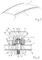
- Fig. 1 shows the vehicle roof of a car with two on each extending in the vehicle longitudinal direction profile strips, as they are also referred to as "roof rails". Such strips serve as load receptacles for cross member of z.
- the strip 2 is suitably closed at both its ends, and fixed at two or more points of its length against a base 1, here against the outside of the body panel of a vehicle body.
- the following description refers to the structural design of these at least two attachment points.
- the profile strip 2 is a hollow profile and in particular a rail profile of a vehicle roof rail, the outside of the body outer panel facing bottom 3 is either closed with only a single, arranged at the attachment openings 4, or is provided with a through opening 4 similar to a slot.
- the first variant is preferable.
- the hollow profile 2 is completely closed.
- the two side walls of the hollow section 2 are closed, but has a side wall in the region of the fastening point described here, but only there, via a relatively small side opening 45, which serves for assembly purposes and is subsequently closed by a cover.
- the strip 2 is a profile strip with a double-chamber profile, because it has, in addition to the first, provided in the bottom 3 with the openings 4 longitudinal channel 2A an externally arranged above the second longitudinal channel 2B, wherein the closed outer wall 2C of the longitudinal channel 2A at the same time the partition between the two longitudinal channels 2A, 2B.
- the second longitudinal channel 2B is closed on all four profile sides.
- annular seal 14 is arranged at each attachment point.
- a flat design foam pad 15th located between the bottom 3 of the bar 2 and the pad 1, so the outside of the body panel.
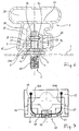
- the body panel 1 is not always considered by itself if it is too thin for a load bearing. Instead, according to the embodiments Fig. 2 and Fig. 3 used to anchor the profiled strip 2, the increased rigidity of a body structure 10, which is located at a distance below the body panel 1.
- the body structure 10 is, for example, a body profile with correspondingly high strength.
- the anchoring parts 5 to be positioned at the individual fastening points can be fastened in advance to the vehicle body, ie before the final assembly of the profile strip.
- a body-anchoring anchoring part 5 is here designed a specially designed bolt. This is, viewed from the inside to the vehicle outside, from a threaded portion 6A, a relatively thick longitudinal section 6, a comparatively slimmer longitudinal section 7 and a longitudinal section 8 together, which widens conically to form an oblique surface to the vehicle outside.
- the conclusion of the anchoring part 5 may form a polygonal section, which facilitates the assembly of the anchoring part 5.
- the anchoring part 5 in the region of the longitudinal section 6.
- the longitudinal section 6 is supported with its underside around an opening of the body structure 10, while the threaded portion 6A is located below the body structure 10 and the opening.
- the anchoring part 5 can be rigidly connected to the body structure 10, wherein the relatively thick longitudinal portion 6 of the anchoring part protrudes through an opening in the body panel 1 therethrough.
- the transition between the long longitudinal section 6 and the slender longitudinal section 7 creates an annular support 16 on which the base 3 of the profiled strip 2 is supported around the opening 4. There is therefore no direct contact of the profiled strip 2 with the body panel 1. Instead, it comes between the profile strip 2 and the body panel 1 only to an indirect connection via the interposed seals 14 and the flat foam pad 15. Both the seals 14 and the foam pad 15 are compressible under pressure.
- the profile strip 2 stretched from the outside against the body panel 1, wherein the seals 14 and the foam pad 15 compress and so a complete seal between the profile strip and the outside of the Body panel is achieved.
- a clamping member 20 is disposed in the longitudinal channel 2A and temporarily positioned.
- the clamping member 20 is preferably made of plastic and is composed of two mutually parallel jaws 21, 22, which are connected via acting as spring elements, elastic bridges 25. Manufacturing technology, it is advantageous if the clamping member including the jaws 21, 22 and the elastic bridges 25 is a one-piece plastic injection molded part.
- the resilient bridges 25 are located at the ends of the jaws 21, 22 pointing in the direction of the longitudinal channel 2A and are designed so that the two jaws 21, 22 are spread apart from each other in the resting state, their inner sides being at a distance A1 from one another. In this state of rest, a jaw 21 is supported under slight spring pressure from the inside against the one side wall, and the other jaw 22 from the inside against the other side wall of the profiled strip 2 under slight spring pressure.
- the correct position of the clamping member 20 is ensured in the profile longitudinal direction. This is achieved on the one hand by the already described concerns of the jaws 21, 22 from the inside against the profile side walls.
- the jaw 21 of the clamping member 20 is provided with lateral projections 27A, 27B. The projections 27A, 27B engage in the side wall 45 provided in the respective side wall and lock the clamping member 20 in the longitudinal direction in the profiled strip 2.
- a rib 28 is advantageous, which is formed on one jaw and abuts against the wall 2C from the inside.
- the jaws 21, 22 are pulled against each other by at least one traction means 40, so that their insides no longer the original distance A1, but only even a smaller distance A2 ( Fig. 5 ), which can also become almost zero.
- a pulling means 40 serve here two screws, of which the first screw 40 in the profile longitudinal direction, and the second screw 40 is arranged in the profile longitudinal direction behind the anchoring part 5.
- the heads 41 of the screws 40 are disposed opposite to the side opening 45. Through the side opening 45, therefore, a corresponding screwing tool can be applied to the screws 40 in order to pull the jaws 21, 22 together while clamping the anchoring part 5 against one another.
- both the jaws 21, 22 and the anchoring part 5 are provided with mutually corresponding ramps or inclined surfaces.
- the anchoring part 5 is provided following the relatively slender longitudinal section 7 with the outwardly conically widening longitudinal section 8 whose maximum diameter is not greater than the diameter of a short step 9 (FIG. Fig. 6 ).
- the jaws 21, 22 are provided with circular segment-shaped and adjoining conical segment-shaped recesses 31, 32, wherein the longitudinal section 7 between the circular segment-shaped recesses, and the conical section 8 between the conical segment-shaped recesses 31, 32 of the jaws 21, 22 is received ,
- the formed on the jaws 21, 22, conical or conical segment clamping surfaces 31, 32 preferably have the same angle to the body outer side, as the conically widening longitudinal section 8 of the anchoring part 5. In this way, the clamping surfaces 31, 32 relatively low friction on the conical section. 8 glide along.
- the horizontal side opening 45 is no longer needed. It can be closed by a suitable, usable therein cover.
- the cover can be color matched to the design of the profile strip 2.
- Fig. 6 has the anchoring part 5 opposite one Fig. 2 significantly shortened longitudinal section 6.
- the attachment of the anchoring part 5 takes place here on the body panel 1, and not on a body structure arranged below.
- Their diameter is smaller than the diameter of the longitudinal section 6, but larger than the diameter of the longitudinal section 7. This results around the step 9 around the annular support 16 for the bottom 3 of the profile.
- the preferably round opening 4 in the bottom 3 of the profile strip has a significantly smaller width than the longitudinal section 6, but only a slightly larger width than the step 9, there is a centering of the opening 4 at the stage 9, and thus a more accurate positioning of the profile strip 2, while this is placed on the vehicle roof.
- the Fig. 7 shows an embodiment of a pulling means 40, with which the clamping member 20 can be tightened centrally.
- a rotatable from the outside by means of a screw winding axle 48 is rotatably mounted in the one jaw 21 .
- Fixed to the winding axis 48 is the central portion of a puller wire 49, which is guided in two-armed clamping member, each arm 50A, 50B extends over each arranged in the jaw 21 deflector 51 to the other jaw 22, and is fixed there.
- each arm 50A, 50B extends over each arranged in the jaw 21 deflector 51 to the other jaw 22, and is fixed there.
- the device described above is suitable not only for the placement of attachments on or in a vehicle body, but also for fastening purposes outside the vehicle area.
Description
Die Erfindung betrifft eine Vorrichtung zum Anordnen einer einen Längskanal aufweisenden Leiste, vorzugsweise eines Hohlprofils, an einer Unterlage, wie z. B. einem Karosserieblech einer Fahrzeugkarosserie, nach dem Oberbegriff des Patentanspruchs 1.The invention relates to a device for arranging a longitudinal channel having bar, preferably a hollow profile, on a base, such. B. a body panel of a vehicle body, according to the preamble of claim 1.
Aus der
Allerdings müssen die Montageschritte zur Befestigung der Relingleisten teils an der Karosserieaußenseite, teils im Fahrzeuginneren oder vom Fahrzeuginneren aus durchgeführt müssen. Dies ist nachteilig, wenn ab einem bestimmten Produktionszeitpunkt Arbeiten im Inneren des Fahrzeugs oder vom Inneren des Fahrzeugs aus nicht mehr möglich oder nicht mehr zulässig sind.However, the assembly steps for fixing the railing must be carried out partly on the outside of the body, partly in the vehicle interior or from the vehicle interior. This is disadvantageous if, at a certain production time, work inside the vehicle or from inside the vehicle is no longer possible or no longer permitted.
Eine gattungsgemäße Vorrichtung zum Anordnen einer Leiste an einer Unterlage ist aus der
Ziel der Erfindung ist es, die abschließende Montage einer innen mit einem Längskanal versehenen Leiste und vorzugsweise eines Hohlprofils auch in solchen Situationen zu ermöglichen, in denen sich Montageschritte nur von außen her erledigen lassen. Eine hierzu geeignete Vorrichtung soll geschaffen werden.The aim of the invention is to allow the final assembly of an internally provided with a longitudinal channel strip and preferably a hollow profile in such situations in which assembly steps can be done only from the outside. A device suitable for this purpose is to be created.
Zur Lösung dieser Aufgabe wird eine Vorrichtung mit den Merkmalen des Anspruchs 1 vorgeschlagen.To solve this problem, a device having the features of claim 1 is proposed.
Eine solche Vorrichtung schafft die Voraussetzung dafür, eine abschließende Montage der Leiste auch in solchen Situationen zu ermöglichen, in denen sich Montageschritte nur von außen her erledigen lassen.Such a device creates the conditions for enabling a final assembly of the strip in such situations in which assembly steps can be done only from the outside.
Von Vorteil ist die Erfindung vor allem im Fahrzeugbau. Ist die Leiste z. B. eine Relingleiste einer Dachreling, und die Unterlage das Außenblech der Fahrzeugkarosserie, lässt sich eine abschließende Montage der Leiste außen an der Fahrzeugkarosserie selbst dann noch durchführen, wenn Arbeiten im Fahrzeuginneren oder vom Fahrzeuginneren aus nicht möglich oder nicht zulässig sind. Stattdessen sind für die abschließende Montage der Leiste nur solche Montageschritte erforderlich, die sich von außen her erledigen lassen.The invention is particularly advantageous in vehicle construction. If the bar z. B. a railing rail of a roof rail, and the pad the outer panel of the vehicle body, a final assembly of the bar outside of the vehicle body even then perform when working in the vehicle or inside the vehicle is not possible or not allowed. Instead, only such assembly steps are required for the final assembly of the bar, which can be done from the outside.
Ein wichtiges konstruktives Element ist ein Verankerungsteil, welches sich durch eine Öffnung im Boden der Leiste hindurch bis in den Längskanal der Leiste erstreckt und, ausgehend von der Unterlage, einen schlankeren Längsabschnitt und daran anschließend einen zum freien Ende des Verankerungsteils hin sich erweiternden Längsabschnitt aufweist. Weiter umfasst die Vorrichtung ein in dem Längskanal angeordnetes Klemmbauteil aus zwei aufeinander zu beweglich ausgebildeten Backen, die jeweils mit einer von innen her gegen den Boden der Leiste anliegenden Druckfläche versehen sind, und zwischen sich den sich erweiternden Längsabschnitt des Verankerungsteils einklemmen.An important constructive element is an anchoring part, which extends through an opening in the bottom of the strip through into the longitudinal channel of the strip and, starting from the base, a slender longitudinal section and then has a to the free end of the anchoring portion extending towards longitudinal section. Furthermore, the device comprises a clamp arranged in the longitudinal channel of two mutually movable to each other formed jaws, which are each provided with an applied from the inside against the bottom of the bar pressure surface, and clamp between them the widening longitudinal portion of the anchoring part.
Bevorzugte Ausgestaltungen der Vorrichtung sind in den Unteransprüchen angegeben.Preferred embodiments of the device are specified in the subclaims.
Mit einer ersten Ausgestaltung wird vorgeschlagen, dass sich jede Backe mit einer gegenüber der Unterlage schräg angeordneten Fläche gegen den sich erweiternden Längsabschnitt des Verankerungsteils abstützt. Zur Verbesserung des aneinander entlang Gleitens der beteiligten schrägen Flächen ist es von Vorteil, wenn die schräg angeordnete Fläche an der Backe einerseits, und die Seitenfläche des sich erweiternden Längsabschnitts des Verankerungsteils andererseits denselben Winkel aufweisen.With a first embodiment, it is proposed that each jaw is supported against the expanding longitudinal section of the anchoring part with a surface arranged obliquely with respect to the base. In order to improve the slanting surfaces involved in sliding along each other, it is advantageous if the obliquely arranged surface on the jaw, on the one hand, and the side surface of the widening longitudinal section of the anchoring part, on the other hand, have the same angle.
Als Verankerungsteil besonders geeignet ist ein Bolzen, wobei ein an dem Bolzen ausgebildeter, vorzugsweise zylindrischer Abschnitt der schlankere Längsabschnitt, und ein an dem Bolzen ausgebildeter Kegelabschnitt der sich erweiternde Längsabschnitt ist. Der schlankere Abschnitt ist zwischen kreissegmentförmigen Ausnehmungen der Backen, und der Kegelabschnitt ist zwischen kegelsegmentförmigen Ausnehmungen der Backen aufgenommen.Particularly suitable as an anchoring part is a bolt, a trained on the bolt, preferably cylindrical portion of the slender longitudinal portion, and a cone portion formed on the bolt is the widening longitudinal portion. The slimmer portion is between circular segment-shaped recesses of the jaws, and the cone portion is received between the cone segment-shaped recesses of the jaws.
Mit einer weiteren Ausgestaltung werden Federelemente vorgeschlagen, welche die zwei Backen voneinander weg beaufschlagen. Vorzugsweise sind die Federelemente einstückig mit den Backen ausgebildete und sich zwischen diesen erstreckende elastische Brücken. Die Brücken können in platzsparender Ausbildung an den in Richtung des Längskanals weisenden Enden der Backen angeformt sein.With a further embodiment spring elements are proposed, which act on the two jaws away from each other. Preferably, the spring elements are integrally formed with the jaws and extending therebetween elastic bridges. The Bridges can be molded in space-saving training at the pointing in the direction of the longitudinal channel ends of the jaws.
Um während der Endmontage der Profilleiste die beiden Backen des Klemmbauteils gegeneinander zu bewegen, wird mit einer weiteren Ausgestaltung ein die Backen verbindendes und aufeinander zu spannendes Zugmittel vorgeschlagen. Ein geeignetes Zugmittel sind zum Beispiel zwei Schrauben, wobei die erste Schraube in Kanallängsrichtung vor, und die zweite Schraube in Kanallängsrichtung hinter dem Verankerungsteil angeordnet ist.In order to move the two jaws of the clamping member against each other during the final assembly of the profile strip, a further embodiment, the jaws connecting and each other to exciting tension means is proposed. A suitable traction means are, for example, two screws, wherein the first screw in the channel longitudinal direction in front, and the second screw in the channel longitudinal direction is arranged behind the anchoring part.
Mit einer weiteren Ausgestaltung wird hinsichtlich der Leiste vorgeschlagen, dass diese auf jenem Längsabschnitt, auf dem sich das Verankerungsteil befindet, mit einer horizontalen Seitenöffnung versehen ist, die durch eine darin einsetzbare Abdeckung verschließbar ist.With a further embodiment, it is proposed with regard to the strip that it is provided on that longitudinal section on which the anchoring part is located, with a horizontal side opening which can be closed by a cover insertable therein.
Ausführungsbeispiele der Vorrichtung zum Anordnen einer einen Längskanal aufweisenden Leiste gegen eine Unterlage werden im Folgenden anhand der zugehörigen Zeichnungen beschrieben. Darin zeigen:
- Fig. 1
- eine perspektivische Ansicht eines PKW-Fahrzeugdachs mit zwei darauf befestigten, eine Dachreling bildenden Leisten in Gestalt von Profilleisten;
- Fig. 2
- einen Schnitt durch die Fahrzeugkarosserie im Bereich einer Befestigung der Profilleiste;
- Fig. 3
- im Bereich der Befestigung eine perspektivische Ansicht auf einen Abschnitt der Profilleiste und ein karosseriefestes Verankerungsteil;
- Fig. 4
- eine perspektivische Ansicht auf ein Klemmbauteil, welches Bestandteil der Vorrichtung zur Befestigung der Profilleiste ist, wobei das Klemmbauteil im Zustand vor der Endmontage wiedergegeben ist;
- Fig. 5
- in einer Draufsicht das Klemmbauteil nach Abschluss der Endmontage;
- Fig. 6
- in einer zweiten Ausführungsform einen Schnitt durch die Fahrzeugkarosserie im Bereich einer der Befestigungen der Profilleiste, und
- Fig. 7
- in einer dritten Ausführungsform eine Draufsicht auf ein Klemmbauteil.
- Fig. 1
- a perspective view of a car-vehicle roof with two mounted thereon, a roof rail forming strips in the form of moldings;
- Fig. 2
- a section through the vehicle body in the region of a fastening of the profile strip;
- Fig. 3
- in the attachment area, a perspective view of a section of the profile strip and a body-anchoring part;
- Fig. 4
- a perspective view of a clamping member which is part of the device for fixing the profile strip, wherein the clamping member is shown in the state before the final assembly;
- Fig. 5
- in a plan view of the clamping member after completion of the final assembly;
- Fig. 6
- in a second embodiment, a section through the vehicle body in the region of one of the fasteners of the profile strip, and
- Fig. 7
- in a third embodiment, a plan view of a clamping member.
Vorzugsweise ist die Leiste 2 an ihren beiden Enden in geeigneter Weise verschlossen, und an zwei oder mehr Stellen ihrer Länge gegen eine Unterlage 1 befestigt, hier gegen die Außenseite des Karosserieblechs einer Fahrzeugkarosserie. Die folgende Beschreibung bezieht sich auf den konstruktiven Aufbau an diesen mindestens zwei Befestigungsstellen.Preferably, the
Gemäß
An seiner dem Boden 3 abgewandten Außenwand 2C ist das Hohlprofil 2 vollständig geschlossen. Auch die beiden Seitenwände des Hohlprofils 2 sind geschlossen, jedoch verfügt die eine Seitenwand im Bereich der hier beschriebenen Befestigungsstelle, aber auch nur dort, über eine relativ kleine Seitenöffnung 45, die Montagezwecken dient und im Anschluss durch eine Abdeckung verschließbar ist.At its bottom wall 3 facing away from the
Beim Ausführungsbeispiel ist die Leiste 2 eine Profilleiste mit Doppelkammerprofil, denn sie weist zusätzlich zu dem ersten, im Boden 3 mit den Öffnungen 4 versehenen Längskanal 2A einen außen darüber angeordneten zweiten Längskanal 2B auf, wobei die geschlossene Außenwand 2C des Längskanals 2A zugleich die Trennwand zwischen den beiden Längskanälen 2A, 2B ist. Der zweite Längskanal 2B ist an allen vier Profilseiten geschlossen. Zwischen dem Boden 3 der Leiste 2 und der Außenseite des Karosserieblechs 1 ist an jeder Befestigungsstelle eine ringförmige Dichtung 14 angeordnet. Außerdem befindet sich zwischen dem Boden 3 der Leiste 2 und der Unterlage 1, also der Außenseite des Karosserieblechs, eine flächig gestaltete Schaumunterlage 15.In the exemplary embodiment, the
Für eine Verankerung der hohe Lasten aufnehmenden Profilleiste 2 ist das Karosserieblech 1 für sich alleine betrachtet nicht immer geeignet, wenn es zu dünnwandig für eine Lastaufnahme ist. Stattdessen wird bei den Ausführungsformen nach
Als karosseriefestes Verankerungsteil 5 dient hier ein in besonderer Weise gestalteter Bolzen. Dieser setzt sich, von innen nach fahrzeugaußen betrachtet, aus einem Gewindeabschnitt 6A, einem relativ dicken Längsabschnitt 6, einem im Vergleich schlankeren Längsabschnitt 7 und einem Längsabschnitt 8 zusammen, der sich unter Bildung einer schrägen Fläche nach fahrzeugaußen hin konisch erweitert.As a body-anchoring
Den Abschluss des Verankerungsteils 5 kann ein Mehrkantabschnitt bilden, der die Montage des Verankerungsteils 5 erleichtert.The conclusion of the anchoring
Seine größte Dicke weist das Verankerungsteil 5 im Bereich des Längsabschnitts 6 auf. Der Längsabschnitt 6 stützt sich mit seiner Unterseite rund um eine Öffnung der Karosseriestruktur 10 ab, während sich der Gewindeabschnitt 6A unterhalb der Karosseriestruktur 10 und der Öffnung befindet. Durch Aufschrauben einer Gewindemutter auf den Gewindeabschnitt 6A lässt sich das Verankerungsteil 5 starr mit der Karosseriestruktur 10 verbinden, wobei der relativ dicke Längsabschnitt 6 des Verankerungsteils durch eine Öffnung im Karosserieblech 1 hindurch ragt.Its largest thickness, the anchoring
Durch den Übergang zwischen dem weiten Längsabschnitt 6 und dem schlanken Längsabschnitt 7 entsteht eine ringförmige Auflage 16, auf der sich der Boden 3 der Profilleiste 2 rund um die Öffnung 4 abstützt. Es besteht daher kein direkter Kontakt der Profilleiste 2 mit dem Karosserieblech 1. Stattdessen kommt es zwischen der Profilleiste 2 und dem Karosserieblech 1 nur zu einer indirekten Verbindung über die dazwischen angeordneten Dichtungen 14 und die flächige Schaumunterlage 15. Sowohl die Dichtungen 14 als auch die Schaumunterlage 15 sind unter Druck kompressibel.The transition between the long
Durch die im Folgenden näher beschriebenen Maßnahmen wird, unter Einsatz des Verankerungsteils 5 als Widerlager, die Profilleiste 2 von außen gegen das Karosserieblech 1 gespannt, wobei sich die Dichtungen 14 und die Schaumunterlage 15 komprimieren und so eine vollständige Abdichtung zwischen der Profilleiste und der Außenseite des Karosserieblechs erzielt wird.By the measures described in more detail below, using the
An jeder Befestigungsstelle und somit dort, wo ein Verankerungsteil 5 durch das Karosserieblech 1 hindurchragt, ist in dem Längskanal 2A ein Klemmbauteil 20 angeordnet und vorläufig positioniert. Das Klemmbauteil 20 besteht vorzugsweise aus Kunststoff und setzt sich aus zwei parallel zueinander angeordneten Backen 21, 22 zusammen, die über als Federelemente wirkende, elastische Brücken 25 verbunden sind. Fertigungstechnisch ist es von Vorteil, wenn das Klemmbauteil einschließlich der Backen 21, 22 und der elastischen Brücken 25 ein einstückiges Kunststoffspritzteil ist.At each attachment point and thus where an anchoring
Die federnden Brücken 25 befinden sich an den in Richtung des Längskanals 2A weisenden Enden der Backen 21, 22 und sind so ausgebildet, dass die beiden Backen 21, 22 im Ruhezustand voneinander weg gespreizt sind, wobei ihre Innenseiten einen Abstand A1 zueinander aufweisen. In diesem Ruhezustand stützt sich die eine Backe 21 unter leichtem Federdruck von innen gegen die eine Seitenwand, und die andere Backe 22 unter leichtem Federdruck von innen gegen die andere Seitenwand der Profilleiste 2 ab.The resilient bridges 25 are located at the ends of the
Während des Aufsetzens der Profilleiste 2 auf die Verankerungsteile 5 ist es von Vorteil, wenn die richtige Lage des Klemmbauteils 20 in Profillängsrichtung sichergestellt ist. Dies wird einerseits durch das bereits beschriebene Anliegen der Backen 21, 22 von innen her gegen die Profilseitenwände erreicht. Als zusätzliche Maßnahme ist die Backe 21 des Klemmbauteils 20 mit seitlichen Vorsprüngen 27A, 27B versehen. Die Vorsprünge 27A, 27B greifen in die in der betreffenden Seitenwand vorhandene Seitenöffnung 45 ein und verriegeln das Klemmbauteil 20 in Längsrichtung in der Profilleiste 2. Für die richtige Lage des Klemmbauteils 20 ist schließlich eine Rippe 28 von Vorteil, die an der einen Backe angeformt ist und von innen gegen die Wand 2C anliegt.During placement of the profiled
Nachdem die Profilleiste auf das Fahrzeugdach aufgesetzt ist, wobei sich das Verankerungsteil 5 zwischen den beiden Backen 21, 22 befindet, werden die Backen 21, 22 durch mindestens ein Zugmittel 40 gegeneinander gezogen, so dass ihre Innenseiten nicht mehr den ursprünglichen Abstand A1, sondern nur noch einen geringeren Abstand A2 (
Als Zugmittel 40 dienen hier zwei Schrauben, von denen die erste Schraube 40 in Profillängsrichtung vor, und die zweite Schraube 40 in Profillängsrichtung hinter dem Verankerungsteil 5 angeordnet ist. Die Köpfe 41 der Schrauben 40 sind gegenüberliegend zu der Seitenöffnung 45 angeordnet. Durch die Seitenöffnung 45 hindurch lässt sich daher ein entsprechendes Schraubwerkzeug an die Schrauben 40 ansetzen, um die Backen 21, 22 unter Einklemmen des Verankerungsteils 5 gegeneinander zu ziehen.As a pulling
Um das gegeneinander Ziehen der Backen 21, 22 in eine nach unten, d. h. zu der Fahrzeugkarosserie hin gerichtete Druckkraft umzulenken, sind sowohl die Backen 21, 22 als auch das Verankerungsteil 5 mit zueinander korrespondierenden Rampen oder schrägen Flächen versehen. Hierzu ist das Verankerungsteil 5 im Anschluss an den relativ schlanken Längsabschnitt 7 mit dem sich nach außen hin kegelförmig erweiternden Längsabschnitt 8 versehen, dessen maximaler Durchmesser nicht größer als der Durchmesser einer kurzen Stufe 9 (
Korrespondierend zu dem Kegelabschnitt 8 sind die Backen 21, 22 mit kreissegmentförmigen und daran anschließenden kegelsegmentförmigen Ausnehmungen 31, 32 versehen, wobei der Längsabschnitt 7 zwischen den kreissegmentförmigen Ausnehmungen, und der Kegelabschnitt 8 zwischen den kegelsegmentförmigen Ausnehmungen 31, 32 der Backen 21, 22 aufgenommen ist.Corresponding to the
Werden die Backen 21, 22 gegeneinander gezogen, kommt es entlang der korrespondierenden Schrägen bzw. Rampen zu einer nach unten gerichteten, resultierenden Kraft auf die Backen, d. h. zu einer Kraft zu der Fahrzeugkarosserie hin. Durch diese resultierende Kraft pressen die Backen 21, 22 mit ihren als Druckflächen 30 dienenden Unterseiten gegen den Boden 3 der Profilleiste 2. Der hierdurch auf die Profilleiste 21 ausgeübte vertikale Druck führt zu dem bereits erwähnten teilweisen Komprimieren der unmittelbar um die jeweilige Öffnung 4 herum angeordneten Dichtung 14 sowie der Schaumunterlage 15.If the
Die an den Backen 21, 22 ausgebildeten, konischen oder kegelsegmentförmigen Klemmflächen 31, 32 weisen vorzugsweise denselben Winkel zur Karosserieaußenseite auf, wie der kegelförmig sich erweiternde Längsabschnitt 8 des Verankerungsteils 5. Auf diese Weise können die Klemmflächen 31, 32 relativ reibungsarm an dem Kegelabschnitt 8 entlang gleiten.The formed on the
Sind die das Zugmittel 40 bildenden Schrauben fest angezogen, wird die horizontale Seitenöffnung 45 nicht mehr benötigt. Sie kann durch eine geeignete, darin einsetzbare Abdeckung verschlossen werden. Die Abdeckung kann farblich auf die Gestaltung der Profilleiste 2 abgestimmt sein.If the screws forming the pulling
Bei der Ausführungsform nach
Die
An den zwei Backen 21, 22 ausgebildete Rastelemente 56, 57 stellen sicher, dass die Backen 21, 22 ihre einmal erreichte Klemmposition dauerhaft beibehalten.On the two
Die voranstehend beschriebene Vorrichtung eignet sich nicht nur für das Anordnen von Anbauteilen an oder in einer Fahrzeugkarosserie, sondern auch für Befestigungszwecke außerhalb des Fahrzeugbereichs.The device described above is suitable not only for the placement of attachments on or in a vehicle body, but also for fastening purposes outside the vehicle area.
- 11
- Unterlage, KarosserieblechUnderlay, body sheet
- 22
- Leiste, HohlprofilStrip, hollow profile
- 2A2A
- Längskanallongitudinal channel
- 2B2 B
- Längskanallongitudinal channel
- 2C2C
- Außenwandouter wall
- 33
- Bodenground
- 44
- Öffnungopening
- 55
- Verankerungsteilanchoring part
- 66
- Längsabschnittlongitudinal section
- 77
- Längsabschnittlongitudinal section
- 88th
- sich erweiternder Längsabschnittexpanding longitudinal section
- 99
- Stufestep
- 1010
- Karosseriestrukturbody structure
- 1414
- Dichtungpoetry
- 1515
- SchaumunterlageFoam mattress
- 1616
- Auflageedition
- 2020
- Klemmbauteilclamping member
- 2121
- Backejaw
- 2222
- Backejaw
- 2525
- elastische Brückeelastic bridge
- 27A27A
- Vorsprunghead Start
- 27B27B
- Vorsprunghead Start
- 2828
- Ripperib
- 3030
- Druckflächeprint area
- 3131
- Klemmflächeclamping surface
- 3232
- Klemmflächeclamping surface
- 4040
- Zugmittel, SchraubeTraction means, screw
- 4141
- Schraubenkopfscrew head
- 4545
- Seitenöffnungside opening
- 4848
- Wickelachsewinding axis
- 4949
- Zugdrahtpull wire
- 50A50A
- Armpoor
- 50 B50 B
- Armpoor
- 5151
- Umlenkungredirection
- 5656
- Rastelementlocking element
- 5757
- Rastelementlocking element
- A1A1
- Abstanddistance
- A2A2
- Abstanddistance
Claims (12)
- Device for arranging a strip (2) on a support (1), with an anchoring part (5) which extends into the strip (2) through an opening (4) in the bottom (3) of the strip (2) and, starting from the support (1), has a relatively slender longitudinal portion (7) and at least one widened longitudinal portion (8), and with a clamping component (20) arranged in the strip (2), characterized in that the strip (2) has a longitudinal channel (2A) into which the anchoring part (5) extends, in that the widened longitudinal portion (8) is designed to widen towards the free end of the anchoring part (5) and in that the clamping component (20) is arranged in the longitudinal channel (2A) and consists of two jaws (21, 22) which are designed to be movable towards one another and which are each provided with a pressing surface (30) bearing from inside against the bottom (3) of the strip (2), said jaws clamping the widening longitudinal portion (8) of the anchoring part (5) between them.
- Device according to Claim 1, characterized in that each jaw (21, 22) is supported against the widening longitudinal portion (8) of the anchoring part (5) by a surface (31, 32) which is arranged obliquely with respect to the support (1).
- Device according to Claim 2, characterized in that, in order for each jaw (21, 22) to bear flat against the anchoring part (5), the obliquely arranged surface (31, 32) and the lateral surface of the widening longitudinal portion (8) have the same angle.
- Device according to one of the preceding claims, characterized in that the anchoring part (5) is a bolt, in that a preferably cylindrical portion integrally formed thereon is the relatively slender longitudinal portion (7) and a conical portion integrally formed thereon is the widening longitudinal portion (8), and in that the relatively slender portion (7) is accommodated between circle-segment-shaped recesses of the jaws (21, 22), and the conical portion (8) is accommodated between circle-segment-shaped recesses of the jaws (21, 22).
- Device according to one of the preceding claims, characterized by spring elements which urge the two jaws (21, 22) away from one another.
- Device according to Claim 5, characterized in that the spring elements are elastic bridges (25) which are formed in one piece with the jaws (21, 22) and extend between them, wherein the elastic bridges (25) are preferably integrally formed on the ends of the jaws (21, 22) that point in the direction of the longitudinal channel (2A).
- Device according to one of the preceding claims, characterized by at least one pulling means (40) which connects the jaws (21, 22) and braces them towards one another.
- Device according to Claim 7, characterized by screws as pulling means (40), wherein a first screw (40) is arranged in front of the anchoring part (5) in the channel longitudinal direction, and a second screw (40) is arranged behind the anchoring part (5) in the channel longitudinal direction.
- Device according to one of the preceding claims, characterized in that the strip (2) is provided with a horizontal side opening (45) on that longitudinal portion on which the anchoring part (5) is situated.
- Device according to Claim 9, characterized in that the side opening (45) is closed by a covering which can be inserted therein.
- Device according to Claim 9 or 10, characterized in that the clamping component (20) is provided with lateral projections (27A, 27B) at the location of the horizontal side opening (45).
- Device according to one of the preceding claims, characterized in that, at the transition between the two longitudinal portions (8, 7), the anchoring part (5) is provided with a peripheral step (9) whose axial length is less than or at most equal to the wall thickness of the bottom (3).
Applications Claiming Priority (2)
| Application Number | Priority Date | Filing Date | Title |
|---|---|---|---|
| DE102013105061.1A DE102013105061A1 (en) | 2013-05-16 | 2013-05-16 | Device for arranging a longitudinal channel having a profile strip on a body panel |
| DE102013109067 | 2013-08-22 |
Publications (2)
| Publication Number | Publication Date |
|---|---|
| EP2803533A1 EP2803533A1 (en) | 2014-11-19 |
| EP2803533B1 true EP2803533B1 (en) | 2016-11-02 |
Family
ID=50685809
Family Applications (1)
| Application Number | Title | Priority Date | Filing Date |
|---|---|---|---|
| EP14167924.1A Not-in-force EP2803533B1 (en) | 2013-05-16 | 2014-05-12 | Device for assembling a rail on a support with a longitudinal channel |
Country Status (1)
| Country | Link |
|---|---|
| EP (1) | EP2803533B1 (en) |
Families Citing this family (1)
| Publication number | Priority date | Publication date | Assignee | Title |
|---|---|---|---|---|
| US20160380439A1 (en) | 2015-06-26 | 2016-12-29 | Lei Shao | Notification techniques for wireless power transfer systems |
Family Cites Families (6)
| Publication number | Priority date | Publication date | Assignee | Title |
|---|---|---|---|---|
| DE4422932A1 (en) * | 1994-07-01 | 1996-01-04 | Happich Fahrzeug Dachsysteme | Vehicle roof rack rail |
| DE19604994A1 (en) * | 1996-02-12 | 1997-08-14 | Happich Fahrzeug Dachsysteme | Fastening arrangement for roof-rail support foot |
| DE19858558B4 (en) * | 1998-12-18 | 2006-04-13 | Jac Products Deutschland Gmbh | Roof rail for vehicles |
| FR2869003B1 (en) | 2004-04-20 | 2007-08-24 | Peugeot Citroen Automobiles Sa | FIXING ELEMENT AND CORRESPONDING VEHICLE |
| DE102009026245A1 (en) | 2009-07-24 | 2011-01-27 | Jac Products Deutschland Gmbh | Device for fixing an attachment, z. B. a railing on a vehicle body |
| DE102010060394A1 (en) | 2009-11-10 | 2011-05-12 | Jac Products Europe Gmbh | Device for mounting attachment externally supporting against body outer panel of vehicle body on body structure, has retaining foot connected with attachment |
-
2014
- 2014-05-12 EP EP14167924.1A patent/EP2803533B1/en not_active Not-in-force
Also Published As
| Publication number | Publication date |
|---|---|
| EP2803533A1 (en) | 2014-11-19 |
Similar Documents
| Publication | Publication Date | Title |
|---|---|---|
| EP2110565B1 (en) | Connection component for attaching an extension element to a carrier element | |
| DE19749219B4 (en) | Non-removable fastening device | |
| DE2262160A1 (en) | FASTENING SYSTEM WITH HIGH STRENGTH | |
| EP3586018B1 (en) | Fastening device and fastening assembly | |
| EP2532568A2 (en) | Device to attach a component, e.g. a railing, to a vehicle body | |
| EP0754595B1 (en) | Variable quick fastening device for a roof luggage-case mounted on roof-rack transvers bars | |
| WO2013037365A1 (en) | Roof load carrier for motor vehicles | |
| DE102008017859B4 (en) | Arrangement for fastening a profile, in particular a hollow profile, to a vehicle roof | |
| DE2754910A1 (en) | Fixing socket for wall panel - has jaws pointing towards insertable bracing unit guided by conical sleeve and drawn together by threaded connection | |
| EP1862356B1 (en) | Retaining clip | |
| EP2803533B1 (en) | Device for assembling a rail on a support with a longitudinal channel | |
| EP1714832B1 (en) | Rail for vehicles | |
| EP2627915A1 (en) | Anchoring device for fastening a component to a carrier element | |
| EP2216205A1 (en) | Roof carrier for motor vehicles | |
| DE202017105765U1 (en) | Fastening device for fastening at least one component | |
| DE102019004829B4 (en) | Support system for supporting part of a structure | |
| EP1571268B1 (en) | Sanitary fitting | |
| EP1243203B1 (en) | Fastening system for slides | |
| DE102017206376B4 (en) | base support | |
| DE2731761B2 (en) | Cavity fastening | |
| DE102013105061A1 (en) | Device for arranging a longitudinal channel having a profile strip on a body panel | |
| AT508129B1 (en) | FASTENING DEVICE FOR A FURNITURE FITTING | |
| WO1982000690A1 (en) | Anchoring bolt | |
| DE202007008397U1 (en) | Furniture system and furniture | |
| DE102017116057B4 (en) | Mounting assembly |
Legal Events
| Date | Code | Title | Description |
|---|---|---|---|
| PUAI | Public reference made under article 153(3) epc to a published international application that has entered the european phase |
Free format text: ORIGINAL CODE: 0009012 |
|
| 17P | Request for examination filed |
Effective date: 20140512 |
|
| AK | Designated contracting states |
Kind code of ref document: A1 Designated state(s): AL AT BE BG CH CY CZ DE DK EE ES FI FR GB GR HR HU IE IS IT LI LT LU LV MC MK MT NL NO PL PT RO RS SE SI SK SM TR |
|
| AX | Request for extension of the european patent |
Extension state: BA ME |
|
| R17P | Request for examination filed (corrected) |
Effective date: 20150511 |
|
| RBV | Designated contracting states (corrected) |
Designated state(s): AL AT BE BG CH CY CZ DE DK EE ES FI FR GB GR HR HU IE IS IT LI LT LU LV MC MK MT NL NO PL PT RO RS SE SI SK SM TR |
|
| GRAP | Despatch of communication of intention to grant a patent |
Free format text: ORIGINAL CODE: EPIDOSNIGR1 |
|
| INTG | Intention to grant announced |
Effective date: 20160607 |
|
| GRAS | Grant fee paid |
Free format text: ORIGINAL CODE: EPIDOSNIGR3 |
|
| GRAA | (expected) grant |
Free format text: ORIGINAL CODE: 0009210 |
|
| AK | Designated contracting states |
Kind code of ref document: B1 Designated state(s): AL AT BE BG CH CY CZ DE DK EE ES FI FR GB GR HR HU IE IS IT LI LT LU LV MC MK MT NL NO PL PT RO RS SE SI SK SM TR |
|
| REG | Reference to a national code |
Ref country code: GB Ref legal event code: FG4D Free format text: NOT ENGLISH |
|
| REG | Reference to a national code |
Ref country code: AT Ref legal event code: REF Ref document number: 841480 Country of ref document: AT Kind code of ref document: T Effective date: 20161115 Ref country code: CH Ref legal event code: EP |
|
| REG | Reference to a national code |
Ref country code: IE Ref legal event code: FG4D Free format text: LANGUAGE OF EP DOCUMENT: GERMAN |
|
| REG | Reference to a national code |
Ref country code: DE Ref legal event code: R096 Ref document number: 502014001821 Country of ref document: DE |
|
| PG25 | Lapsed in a contracting state [announced via postgrant information from national office to epo] |
Ref country code: LV Free format text: LAPSE BECAUSE OF FAILURE TO SUBMIT A TRANSLATION OF THE DESCRIPTION OR TO PAY THE FEE WITHIN THE PRESCRIBED TIME-LIMIT Effective date: 20161102 |
|
| REG | Reference to a national code |
Ref country code: NL Ref legal event code: MP Effective date: 20161102 |
|
| REG | Reference to a national code |
Ref country code: LT Ref legal event code: MG4D |
|
| PG25 | Lapsed in a contracting state [announced via postgrant information from national office to epo] |
Ref country code: NL Free format text: LAPSE BECAUSE OF FAILURE TO SUBMIT A TRANSLATION OF THE DESCRIPTION OR TO PAY THE FEE WITHIN THE PRESCRIBED TIME-LIMIT Effective date: 20161102 Ref country code: NO Free format text: LAPSE BECAUSE OF FAILURE TO SUBMIT A TRANSLATION OF THE DESCRIPTION OR TO PAY THE FEE WITHIN THE PRESCRIBED TIME-LIMIT Effective date: 20170202 Ref country code: GR Free format text: LAPSE BECAUSE OF FAILURE TO SUBMIT A TRANSLATION OF THE DESCRIPTION OR TO PAY THE FEE WITHIN THE PRESCRIBED TIME-LIMIT Effective date: 20170203 Ref country code: LT Free format text: LAPSE BECAUSE OF FAILURE TO SUBMIT A TRANSLATION OF THE DESCRIPTION OR TO PAY THE FEE WITHIN THE PRESCRIBED TIME-LIMIT Effective date: 20161102 Ref country code: SE Free format text: LAPSE BECAUSE OF FAILURE TO SUBMIT A TRANSLATION OF THE DESCRIPTION OR TO PAY THE FEE WITHIN THE PRESCRIBED TIME-LIMIT Effective date: 20161102 |
|
| REG | Reference to a national code |
Ref country code: FR Ref legal event code: PLFP Year of fee payment: 4 |
|
| PG25 | Lapsed in a contracting state [announced via postgrant information from national office to epo] |
Ref country code: ES Free format text: LAPSE BECAUSE OF FAILURE TO SUBMIT A TRANSLATION OF THE DESCRIPTION OR TO PAY THE FEE WITHIN THE PRESCRIBED TIME-LIMIT Effective date: 20161102 Ref country code: PL Free format text: LAPSE BECAUSE OF FAILURE TO SUBMIT A TRANSLATION OF THE DESCRIPTION OR TO PAY THE FEE WITHIN THE PRESCRIBED TIME-LIMIT Effective date: 20161102 Ref country code: PT Free format text: LAPSE BECAUSE OF FAILURE TO SUBMIT A TRANSLATION OF THE DESCRIPTION OR TO PAY THE FEE WITHIN THE PRESCRIBED TIME-LIMIT Effective date: 20170302 Ref country code: HR Free format text: LAPSE BECAUSE OF FAILURE TO SUBMIT A TRANSLATION OF THE DESCRIPTION OR TO PAY THE FEE WITHIN THE PRESCRIBED TIME-LIMIT Effective date: 20161102 Ref country code: FI Free format text: LAPSE BECAUSE OF FAILURE TO SUBMIT A TRANSLATION OF THE DESCRIPTION OR TO PAY THE FEE WITHIN THE PRESCRIBED TIME-LIMIT Effective date: 20161102 Ref country code: IS Free format text: LAPSE BECAUSE OF FAILURE TO SUBMIT A TRANSLATION OF THE DESCRIPTION OR TO PAY THE FEE WITHIN THE PRESCRIBED TIME-LIMIT Effective date: 20170302 Ref country code: RS Free format text: LAPSE BECAUSE OF FAILURE TO SUBMIT A TRANSLATION OF THE DESCRIPTION OR TO PAY THE FEE WITHIN THE PRESCRIBED TIME-LIMIT Effective date: 20161102 |
|
| PG25 | Lapsed in a contracting state [announced via postgrant information from national office to epo] |
Ref country code: DK Free format text: LAPSE BECAUSE OF FAILURE TO SUBMIT A TRANSLATION OF THE DESCRIPTION OR TO PAY THE FEE WITHIN THE PRESCRIBED TIME-LIMIT Effective date: 20161102 Ref country code: EE Free format text: LAPSE BECAUSE OF FAILURE TO SUBMIT A TRANSLATION OF THE DESCRIPTION OR TO PAY THE FEE WITHIN THE PRESCRIBED TIME-LIMIT Effective date: 20161102 Ref country code: SK Free format text: LAPSE BECAUSE OF FAILURE TO SUBMIT A TRANSLATION OF THE DESCRIPTION OR TO PAY THE FEE WITHIN THE PRESCRIBED TIME-LIMIT Effective date: 20161102 Ref country code: RO Free format text: LAPSE BECAUSE OF FAILURE TO SUBMIT A TRANSLATION OF THE DESCRIPTION OR TO PAY THE FEE WITHIN THE PRESCRIBED TIME-LIMIT Effective date: 20161102 Ref country code: CZ Free format text: LAPSE BECAUSE OF FAILURE TO SUBMIT A TRANSLATION OF THE DESCRIPTION OR TO PAY THE FEE WITHIN THE PRESCRIBED TIME-LIMIT Effective date: 20161102 |
|
| REG | Reference to a national code |
Ref country code: DE Ref legal event code: R097 Ref document number: 502014001821 Country of ref document: DE |
|
| PG25 | Lapsed in a contracting state [announced via postgrant information from national office to epo] |
Ref country code: SM Free format text: LAPSE BECAUSE OF FAILURE TO SUBMIT A TRANSLATION OF THE DESCRIPTION OR TO PAY THE FEE WITHIN THE PRESCRIBED TIME-LIMIT Effective date: 20161102 Ref country code: BG Free format text: LAPSE BECAUSE OF FAILURE TO SUBMIT A TRANSLATION OF THE DESCRIPTION OR TO PAY THE FEE WITHIN THE PRESCRIBED TIME-LIMIT Effective date: 20170202 Ref country code: LU Free format text: LAPSE BECAUSE OF NON-PAYMENT OF DUE FEES Effective date: 20170531 |
|
| PLBE | No opposition filed within time limit |
Free format text: ORIGINAL CODE: 0009261 |
|
| STAA | Information on the status of an ep patent application or granted ep patent |
Free format text: STATUS: NO OPPOSITION FILED WITHIN TIME LIMIT |
|
| 26N | No opposition filed |
Effective date: 20170803 |
|
| PG25 | Lapsed in a contracting state [announced via postgrant information from national office to epo] |
Ref country code: SI Free format text: LAPSE BECAUSE OF FAILURE TO SUBMIT A TRANSLATION OF THE DESCRIPTION OR TO PAY THE FEE WITHIN THE PRESCRIBED TIME-LIMIT Effective date: 20161102 |
|
| REG | Reference to a national code |
Ref country code: CH Ref legal event code: PL |
|
| PG25 | Lapsed in a contracting state [announced via postgrant information from national office to epo] |
Ref country code: MC Free format text: LAPSE BECAUSE OF FAILURE TO SUBMIT A TRANSLATION OF THE DESCRIPTION OR TO PAY THE FEE WITHIN THE PRESCRIBED TIME-LIMIT Effective date: 20161102 |
|
| REG | Reference to a national code |
Ref country code: IE Ref legal event code: MM4A |
|
| PG25 | Lapsed in a contracting state [announced via postgrant information from national office to epo] |
Ref country code: CH Free format text: LAPSE BECAUSE OF NON-PAYMENT OF DUE FEES Effective date: 20170531 Ref country code: LI Free format text: LAPSE BECAUSE OF NON-PAYMENT OF DUE FEES Effective date: 20170531 |
|
| PG25 | Lapsed in a contracting state [announced via postgrant information from national office to epo] |
Ref country code: LU Free format text: LAPSE BECAUSE OF NON-PAYMENT OF DUE FEES Effective date: 20170512 |
|
| REG | Reference to a national code |
Ref country code: BE Ref legal event code: MM Effective date: 20170531 |
|
| PG25 | Lapsed in a contracting state [announced via postgrant information from national office to epo] |
Ref country code: IE Free format text: LAPSE BECAUSE OF NON-PAYMENT OF DUE FEES Effective date: 20170512 |
|
| REG | Reference to a national code |
Ref country code: FR Ref legal event code: PLFP Year of fee payment: 5 |
|
| PG25 | Lapsed in a contracting state [announced via postgrant information from national office to epo] |
Ref country code: BE Free format text: LAPSE BECAUSE OF NON-PAYMENT OF DUE FEES Effective date: 20170531 |
|
| PG25 | Lapsed in a contracting state [announced via postgrant information from national office to epo] |
Ref country code: MT Free format text: LAPSE BECAUSE OF FAILURE TO SUBMIT A TRANSLATION OF THE DESCRIPTION OR TO PAY THE FEE WITHIN THE PRESCRIBED TIME-LIMIT Effective date: 20161102 |
|
| GBPC | Gb: european patent ceased through non-payment of renewal fee |
Effective date: 20180512 |
|
| PG25 | Lapsed in a contracting state [announced via postgrant information from national office to epo] |
Ref country code: GB Free format text: LAPSE BECAUSE OF NON-PAYMENT OF DUE FEES Effective date: 20180512 |
|
| PG25 | Lapsed in a contracting state [announced via postgrant information from national office to epo] |
Ref country code: HU Free format text: LAPSE BECAUSE OF FAILURE TO SUBMIT A TRANSLATION OF THE DESCRIPTION OR TO PAY THE FEE WITHIN THE PRESCRIBED TIME-LIMIT; INVALID AB INITIO Effective date: 20140512 |
|
| PGFP | Annual fee paid to national office [announced via postgrant information from national office to epo] |
Ref country code: DE Payment date: 20190617 Year of fee payment: 6 Ref country code: IT Payment date: 20190521 Year of fee payment: 6 |
|
| PGFP | Annual fee paid to national office [announced via postgrant information from national office to epo] |
Ref country code: FR Payment date: 20190521 Year of fee payment: 6 |
|
| PG25 | Lapsed in a contracting state [announced via postgrant information from national office to epo] |
Ref country code: CY Free format text: LAPSE BECAUSE OF FAILURE TO SUBMIT A TRANSLATION OF THE DESCRIPTION OR TO PAY THE FEE WITHIN THE PRESCRIBED TIME-LIMIT Effective date: 20161102 |
|
| PG25 | Lapsed in a contracting state [announced via postgrant information from national office to epo] |
Ref country code: MK Free format text: LAPSE BECAUSE OF FAILURE TO SUBMIT A TRANSLATION OF THE DESCRIPTION OR TO PAY THE FEE WITHIN THE PRESCRIBED TIME-LIMIT Effective date: 20161102 |
|
| PG25 | Lapsed in a contracting state [announced via postgrant information from national office to epo] |
Ref country code: TR Free format text: LAPSE BECAUSE OF FAILURE TO SUBMIT A TRANSLATION OF THE DESCRIPTION OR TO PAY THE FEE WITHIN THE PRESCRIBED TIME-LIMIT Effective date: 20161102 |
|
| PG25 | Lapsed in a contracting state [announced via postgrant information from national office to epo] |
Ref country code: AL Free format text: LAPSE BECAUSE OF FAILURE TO SUBMIT A TRANSLATION OF THE DESCRIPTION OR TO PAY THE FEE WITHIN THE PRESCRIBED TIME-LIMIT Effective date: 20161102 |
|
| REG | Reference to a national code |
Ref country code: AT Ref legal event code: MM01 Ref document number: 841480 Country of ref document: AT Kind code of ref document: T Effective date: 20190512 |
|
| PG25 | Lapsed in a contracting state [announced via postgrant information from national office to epo] |
Ref country code: AT Free format text: LAPSE BECAUSE OF NON-PAYMENT OF DUE FEES Effective date: 20190512 |
|
| REG | Reference to a national code |
Ref country code: DE Ref legal event code: R119 Ref document number: 502014001821 Country of ref document: DE |
|
| PG25 | Lapsed in a contracting state [announced via postgrant information from national office to epo] |
Ref country code: FR Free format text: LAPSE BECAUSE OF NON-PAYMENT OF DUE FEES Effective date: 20200531 |
|
| PG25 | Lapsed in a contracting state [announced via postgrant information from national office to epo] |
Ref country code: DE Free format text: LAPSE BECAUSE OF NON-PAYMENT OF DUE FEES Effective date: 20201201 |
|
| PG25 | Lapsed in a contracting state [announced via postgrant information from national office to epo] |
Ref country code: IT Free format text: LAPSE BECAUSE OF NON-PAYMENT OF DUE FEES Effective date: 20200512 |