EP3696328A1 - Vorrichtung und verfahren zum einbau von vertikalen wühltierschutzgittern - Google Patents
Vorrichtung und verfahren zum einbau von vertikalen wühltierschutzgittern Download PDFInfo
- Publication number
- EP3696328A1 EP3696328A1 EP20401006.0A EP20401006A EP3696328A1 EP 3696328 A1 EP3696328 A1 EP 3696328A1 EP 20401006 A EP20401006 A EP 20401006A EP 3696328 A1 EP3696328 A1 EP 3696328A1
- Authority
- EP
- European Patent Office
- Prior art keywords
- shaped
- grid
- sheet
- plate
- cover
- Prior art date
- Legal status (The legal status is an assumption and is not a legal conclusion. Google has not performed a legal analysis and makes no representation as to the accuracy of the status listed.)
- Granted
Links
Images



Classifications
-
- E—FIXED CONSTRUCTIONS
- E02—HYDRAULIC ENGINEERING; FOUNDATIONS; SOIL SHIFTING
- E02D—FOUNDATIONS; EXCAVATIONS; EMBANKMENTS; UNDERGROUND OR UNDERWATER STRUCTURES
- E02D13/00—Accessories for placing or removing piles or bulkheads, e.g. noise attenuating chambers
- E02D13/02—Accessories for placing or removing piles or bulkheads, e.g. noise attenuating chambers specially adapted for placing or removing bulkheads
-
- A—HUMAN NECESSITIES
- A01—AGRICULTURE; FORESTRY; ANIMAL HUSBANDRY; HUNTING; TRAPPING; FISHING
- A01G—HORTICULTURE; CULTIVATION OF VEGETABLES, FLOWERS, RICE, FRUIT, VINES, HOPS OR SEAWEED; FORESTRY; WATERING
- A01G13/00—Protection of plants
- A01G13/10—Devices for affording protection against animals, birds or other pests
-
- A—HUMAN NECESSITIES
- A01—AGRICULTURE; FORESTRY; ANIMAL HUSBANDRY; HUNTING; TRAPPING; FISHING
- A01M—CATCHING, TRAPPING OR SCARING OF ANIMALS; APPARATUS FOR THE DESTRUCTION OF NOXIOUS ANIMALS OR NOXIOUS PLANTS
- A01M29/00—Scaring or repelling devices, e.g. bird-scaring apparatus
- A01M29/30—Scaring or repelling devices, e.g. bird-scaring apparatus preventing or obstructing access or passage, e.g. by means of barriers, spikes, cords, obstacles or sprinkled water
-
- E—FIXED CONSTRUCTIONS
- E02—HYDRAULIC ENGINEERING; FOUNDATIONS; SOIL SHIFTING
- E02D—FOUNDATIONS; EXCAVATIONS; EMBANKMENTS; UNDERGROUND OR UNDERWATER STRUCTURES
- E02D7/00—Methods or apparatus for placing sheet pile bulkheads, piles, mouldpipes, or other moulds
- E02D7/02—Placing by driving
-
- E—FIXED CONSTRUCTIONS
- E02—HYDRAULIC ENGINEERING; FOUNDATIONS; SOIL SHIFTING
- E02D—FOUNDATIONS; EXCAVATIONS; EMBANKMENTS; UNDERGROUND OR UNDERWATER STRUCTURES
- E02D7/00—Methods or apparatus for placing sheet pile bulkheads, piles, mouldpipes, or other moulds
- E02D7/18—Placing by vibrating
Definitions
- the invention relates to a device and a method for installing vertical burrowing protection grids and is used in particular for bank fortifications and embankments as protection against damage by burrowing animals.
- beaver protection grids are placed on embankments and installed as deep as possible in the foot area (connection to the water) (see also leaflets 247/1997 of the DVWK).
- burglar protection grids takes place wherever e.g. must be protected from damage by beavers or other burrowing animals, bank reinforcements or embankments.
- the feet of these earthworks have so far been secured by installing protective grids vertically in a temporary open trench.
- protective grids vertically in a temporary open trench.
- complex shoring, earthwork and water retention work are necessary for this, or expensive steel sheet piling is installed.
- an animal deterrent device consisting of a metal grille that can be arranged or arranged on an embankment of a basin containing water or a water-carrying channel, an anchoring device and a means to prevent the metal grille from being raised from the embankment.
- the anchoring device prevents downward movement of the metal grid.
- Such protective grids can easily be undermined by the animals to be repelled.
- the pamphlet DE 94 18 197 U1 describes a garden bed border made of plastic sheets for protection against voles and snails. Pluggable plastic plates are described which can be plugged into drawn plastic posts. The additional grids are designed in different lengths. Posts, plates and, if necessary, grids are dug in to border the garden bed. The enclosure creates a natural obstacle for voles, but this device is not suitable for bank reinforcement against larger rodents.
- the object of the invention is to develop a device and a method for installing vertical burrowing protection grids, which has a simple structural design and easily and economically ensures protection of bank fortifications and embankments from burrowing animals such as beavers, muskrats and other pests.
- the device consists of two shaped sheets coupled to one another, which can accommodate protective grids or mats with a width of 1.00 m to 4.00 m and a length of up to 6.00 m.
- the two shaped sheets form the protective cover for the grille to prevent damage during installation.
- the two shaped sheets (carrier and cover) are joined together at the bottom by means of a hook connection and at the top by a bolt connection. As a result, the sheets can be detached from one another after installation in the floor area to be protected and can be individually pulled out and used again.
- the mounting / fastening for the protective grille to be installed is located on the carrier plate.
- On the other shaped sheet (cover) there is a reinforced sheet to accommodate the clamping jaws of a conventional sheet pile vibrator or ram.
- the desired overlap / intersection of the protective grille is ensured by at least one guide plate inserted into the device, so that a closed underground protective barrier is created.
- the guide plate is placed on the carrier plate.
- the guide plates can be countered by a lateral and upper rail Simply be secured from slipping.
- the protective grille supplied as a roll or pre-assembled mat, is attached to the hook on the carrier plate. Using an angle grinder or wire cutter, the protective grille protruding above the carrier board can be cut off. Now the second sheet metal is placed as a cover on the carrier plate in such a way that they are connected to one another at the bottom by simply hooking them in. At the top, a non-positive connection is established between the two shaped sheets (carrier and cover) by means of bolts. The protective grille is now between the two sheets.
- the device is now set up so that it can be picked up by means of a sheet pile wall vibrator or ram (clamping area on the cover plate).
- the device with the protective grille is installed in the intended structure axis using a conventional sheet pile wall vibrator or ram. Now the upper bolts are loosened and the two shaped sheets are pulled individually.
- the protective grille and the guide plate remain in the floor.
- the installation of the next segment is carried out as described above, but the device is pressed against the guide plate that has remained in the ground and sunk. This ensures the desired close-fitting overlap of the joint area.
- the guide rail from the first operation can now be pulled out and reused for the next operation.
- the joint area can also be secured by means of an edge reinforcement so that it is prevented from being levered apart. This is particularly necessary for beaver protection measures.
- a closed underground barrier can thus be created.
- the protective grids can be installed vertically in the floor areas to be secured in various dimensions and types in a closed construction.
- the complex preparatory work can thus be omitted. This makes protection against burrowing animals such as beavers, muskrats and other pests easy and economical to produce.
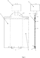
- Figure 1 shows a first shaped sheet 1 in the form of the carrier, the first shaped sheet 1 having teeth 2 for holding the grid. Furthermore, a bracket 3 with hook straps is arranged at the lower end.
- FIG 2 a device is shown in a front and side view.
- the second shaped sheet 4 is designed in the form of the cover and has a reinforced sheet 4.1 for receiving the clamping jaws of a conventional sheet pile wall vibrator 5 or a ram 5.
- the first and second shaped sheets 1, 4 are connected to one another by means of holding elements at an upper end and a lower end such that the upper holding element is designed in the form of bolts 6 and the lower holding element in the form of a hook connection with hook 7.
- the grid 8 is arranged between the first and second shaped sheets 1, 4.
- the device has a guide plate 9 which is placed on the first shaped sheet 1 and which is simply secured against slipping by simply being clamped between the shaped sheet 1 and 4.
- a guide plate 9 is shown in first and second side views in FIG Figure 3 shown.
- Figure 4 shows the arrangement of the protective grille in a plan view.
- the grids 8 have a width of 1.5 to 4 m and are preferably arranged with an overlap at the joint of 0-50 cm, depending on the requirements.
- the device is shown with an inserted grid and guide plate, the device being pressed against the guide plate.
- FIG. 5 a schematic representation of a road pavement is shown.
- the grid 8 is mounted in an edge area R of a road S.
- the procedure can be divided into three Process steps are subdivided after the first insertion of a grid.
- a first process step after the installation of the device, consisting of the first and second shaped sheet 1, 4, it is pulled out of the ground, the grid 8 and a guide sheet 9 remain in the ground.
- the device is again equipped with a grid 8 and a further guide plate 9a.
- the installation then follows, using the guide plate 9 that has remained in the floor as a guide.
- the device and the first guide plate 9 are pulled out of the ground and then equipped with a further grid 8 and the drawn guide plate 9. These steps are repeated until the edge area R is secured according to the required length.
Landscapes
- Life Sciences & Earth Sciences (AREA)
- Engineering & Computer Science (AREA)
- General Life Sciences & Earth Sciences (AREA)
- Mining & Mineral Resources (AREA)
- Paleontology (AREA)
- Civil Engineering (AREA)
- General Engineering & Computer Science (AREA)
- Structural Engineering (AREA)
- Birds (AREA)
- Zoology (AREA)
- Environmental Sciences (AREA)
- Health & Medical Sciences (AREA)
- General Health & Medical Sciences (AREA)
- Toxicology (AREA)
- Insects & Arthropods (AREA)
- Pest Control & Pesticides (AREA)
- Wood Science & Technology (AREA)
- Catching Or Destruction (AREA)
Abstract
Description
- Die Erfindung betrifft eine Vorrichtung und ein Verfahren zum Einbau von vertikalen Wühltierschutzgittern und findet insbesondere für Uferbefestigungen und Böschungen als Schutz vor Beschädigungen durch Wühltiere Anwendung.
- Durch die Wiederverbreitung des Bibers in Mitteleuropa sind umfangreiche Maßnahmen notwendig, um Erddämme, Straßen und Uferbereiche zu schützen. Dafür werden Biberschutzgitter auf Böschungen aufgelegt und im Fußbereich (Anschluss an das Gewässer) möglichst tief eingebaut (siehe hierzu auch die Merkblätter 247/1997 des DVWK).
- Der Einbau von Wühltierschutzgittern erfolgt überall dort, wo z.B. durch Biber oder andere Wühltiere, Uferbefestigungen oder Böschungen vor Schäden geschützt werden müssen. Die Fußsicherung dieser Erdbauwerke erfolgte bisher durch den vertikalen Einbau von Schutzgittern in einem temporären offenen Graben. Dafür sind entsprechend aufwendige Verbau-, Erd-, und Wasserhaltungsarbeiten notwendig, beziehungsweise werden kostenintensive Stahlspundwände eingebaut.
- Aus der Druckschrift
DE 20 2015 105 518 U1 ist eine Tierabwehreinrichtung beschrieben, bestehend aus einem an einer Böschung eines Wasser enthaltenden Beckens oder eines Wasser führenden Kanals anordenbaren bzw. angeordneten Metallgitter, aus einer Verankerungseinrichtung sowie aus einem Mittel, um eine Anhebung des Metallgitters von der Böschung zu unterbinden. Die Verankerungseinrichtung verhindert eine nach unten gerichtete Bewegung des Metallgitters. Derartige Schutzgitter können problemlos von den abzuwehrenden Tieren untergraben werden. - Die Druckschrift
DE 94 18 197 U1 beschreibt eine Gartenbeeteinfassung aus Kunststoffplatten zum Schutz vor Wühlmäusen und Schnecken. Es werden zusammensteckbare Kunststoffplatten beschrieben, die in gezogene Kunststoffpfosten steckbar sind. Die Zusatzgitter sind in verschiedenen Längen ausgebildet. Als Gartenbeeteinfassung werden Pfosten, Platte, und bei Bedarf Gitter eingegraben. Durch die Einfassung entsteht ein natürliches Hindernis für Wühlmäuse, für eine Uferbefestigung gegen größere Nagetiere ist diese Vorrichtung jedoch nicht geeignet. - In der Druckschrift
DE 299 09 450 U1 wird die Herstellung eines geschlossenen Schutzkorbes in verschiedenen Größen aus Drahtgeflecht beschrieben, wobei der Schutzkorb das Eindringen von Nagetieren in das Wurzelwerk von Bäumen, Sträuchern und Stauden und deren Verbissschäden verhindert. Auch dieser Schutzkorb ist für den Schutz von Uferbefestigungen nicht geeignet. - Aufgabe der Erfindung ist es, eine Vorrichtung und ein Verfahren zum Einbau von vertikalen Wühltierschutzgittern zu entwickeln, die einen einfachen konstruktiven Aufbau aufweist und einen Schutz von Uferbefestigungen und Böschungen vor Wühltieren wie Biber, Bisamratten und anderen Schadtieren leicht und wirtschaftlich gewährleistet.
- Diese Aufgabe wird mit den kennzeichnenden Merkmalen des ersten und sechsten Patentanspruchs gelöst.
- Vorteilhafte Ausgestaltungen ergeben sich aus den Unteransprüchen.
- Die Vorrichtung besteht aus zwei miteinander gekoppelten Formblechen, die Schutzgitter oder Matten mit einer Breite von 1,00 m bis 4,00 m bei einer Länge bis zu 6,00 m aufnehmen können. Die beiden Formbleche bilden die Schutzhülle für das Gitter um Schäden beim Einbau zu vermeiden. Die beiden Formbleche (Träger und Deckel) werden unten mittels einer Hakenverbindung und oben durch eine Bolzenverbindung zusammengefügt. Dadurch lassen sich die Bleche nach dem Einbau in den zu schützenden Bodenbereich voneinander lösen und können einzeln wieder gezogen und weiterverwendet werden.
An dem Trägerblech befindet sich die Aufnahme / Befestigung für das einzubauende Schutzgitter.
An dem anderen Formblech (Deckel) befindet sich ein verstärktes Blech zur Aufnahme für die Klemmbacken eines konventionellen Spundwandrüttlers oder Ramme. - Durch wenigstens ein eingelegtes Führungsblech in die Vorrichtung wird die gewünschte Überlappung / Überschneidung des Schutzgitters sichergestellt, so dass eine geschlossene unterirdische Schutzbarriere entsteht.
- Das Führungsblech wird auf das Trägerblech aufgelegt. In einer alternativen Ausgestaltung können durch eine seitliche und obere Schiene die Führungsbleche gegen Verrutschen einfach gesichert sein. Das als Rolle oder vorkonfektionierte Matte gelieferte Schutzgitter wird an den Haken des Trägerbleches befestigt.
Mittels Winkelschleifer oder Drahtschneider kann das oben über die Trägertafel hinausstehende Schutzgitter abgetrennt werden.
Nunmehr wird die zweite Blechtafel als Deckel so auf das Trägerblech aufgelegt, dass diese unten durch einfaches Einhaken miteinander verbunden sind. Oben wird mittels Bolzen eine kraftschlüssige Verbindung zwischen den beiden Formblechen (Träger und Deckel) hergestellt. Das Schutzgitter befindet sich jetzt zwischen den beiden Blechen. Die Vorrichtung wird nunmehr so aufgerichtet, dass diese mittels eines Spundwandrüttlers oder Ramme aufgenommen werden kann (Klemmbereich an dem Deckelblech).
Die Vorrichtung mit dem Schutzgitter wird mittels eines herkömmlichen Spundwandrüttlers oder Ramme in die vorgesehene Bauwerksachse eingebaut.
Nunmehr werden die oberen Bolzen gelöst und die beiden Formbleche werden einzeln gezogen. - Dabei verbleiben das Schutzgitter und das Führungsblech im Boden.
Der Einbau des nächsten Segmentes erfolgt wie vor beschrieben, jedoch wird die Vorrichtung an dem im Boden verbliebenen Führungsblech angedrückt und abgeteuft. Damit ist die gewünschte enganliegende Überlappung des Stoßbereiches gewährleistet. Die Führungsschiene aus dem ersten Vorgang kann jetzt gezogen werden und für den nächsten Arbeitsgang wiederverwendet werden.
Der Stoßbereich kann zusätzlich mittels einer Randverstärkung gesichert werden, so dass ein Auseinanderhebeln vermieden wird. Dies ist insbesondere bei Biberschutzmaßnahmen erforderlich. - Somit kann eine geschlossene unterirdische Barriere hergestellt werden.
- Mit der neuen Vorrichtung und Verfahren lassen sich die Schutzgitter in verschiedenen Abmessungen und Typen in geschlossener Bauweise vertikal in die zu sichernden Bodenbereiche einbauen. Die aufwendigen Vorarbeiten können damit entfallen. Damit ist der Schutz vor Wühltieren wie Biber, Bisamratten und anderen Schadtieren leicht und wirtschaftlich herzustellen.
- Die Erfindung wird nachfolgend mittels Zeichnungen dargestellt.
- Es zeigen:
- Figur 1
- ein erstes Formblech in Form des Trägers,
- Figur 2
- eine erfindungsgemäße Darstellung der Vorrichtung in einer Vorder- und Seitenansicht,
- Figur 3
- eine Seitenansicht der Führungsbleche,
- Figur 4
- eine Draufsicht auf ein mittels der Vorrichtung eingebrachtes Schutzgitter,
- Figur 5
- eine schematische Darstellung des Verfahrens an einer Straßenbefestigung.
-
Figur 1 zeigt ein erstes Formblech 1 in Form des Trägers, wobei das erste Formblech 1 Zähne 2 zum Halten des Gitters aufweist. Des Weiteren ist am unteren Ende eine Konsole 3 mit Hakenlaschen angeordnet. - In
Figur 2 wird eine Vorrichtung in einer Vorder- und Seitenansicht dargestellt. Das zweite Formblech 4 ist in Form des Deckels ausgebildet und weist ein verstärktes Blech 4.1 zur Aufnahme für die Klemmbacken eines konventionellen Spundwandrüttlers 5 oder einer Ramme 5 auf.
Das erste und zweite Formblech 1, 4 sind mittels Halteelementen an einem oberen Ende und einem unteren Ende miteinander verbunden derart, dass das obere Halteelement in Form von Bolzen 6 und das untere Halteelement in Form einer Hakenverbindung mit Haken 7 ausgebildet ist. Zwischen dem ersten und zweiten Formblech 1, 4 ist das Gitter 8 angeordnet. - Die Vorrichtung weist ein, auf dem ersten Formblech 1 aufgelegtes Führungsblech 9 auf, das durch einfaches Einklemmen zwischen dem Formblech 1 und 4 gegen Verrutschen einfach gesichert sind. Ein Führungsblech 9 ist in einer ersten und zweiten Seitenansicht in
Figur 3 dargestellt. -
Figur 4 zeigt die Anordnung des Schutzgitters in einer Draufsicht. Die Gitter 8 weisen eine Breite von 1,5 bis 4m auf und werden vorzugsweise mit einer Überlappung am Stoß von 0 - 50 cm je nach Anforderung angeordnet. Im oberen Bereich der Figur ist die Vorrichtung mit eingelegtem Gitter und Führungsblech dargestellt, wobei die Vorrichtung an dem Führungsblech angedrückt wurde. - In
Figur 5 ist eine schematische Darstellung einer Straßenbefestigung dargestellt. Das Gitter 8 wird in einem Randbereich R einer Straße S montiert. Das Verfahren kann in drei Verfahrensschritte nach dem ersten Einsetzen eines Gitters unterteilt werden. In einem ersten Verfahrensschritt nach dem Einbau der Vorrichtung, bestehend aus dem ersten und zweiten Formblech 1, 4, wird diese aus dem Erdreich gezogen, es verbleibt das Gitter 8 und ein Führungsblech 9 im Boden.
Im nächsten Schritt wird die Vorrichtung erneut mit einem Gitter 8 und einem weiteren Führungsblech 9a bestückt. Es folgt der Einbau, wobei das im Boden verbliebene Führungsblech 9 als Führung verwendet wird.
Im dritten Schritt wird die Vorrichtung und das erste Führungsblech 9 aus dem Boden gezogen und folgend mit einem weiteren Gitter 8 und dem gezogenen Führungsblech 9 bestückt. Diese Schritte wiederholen sich, bis der Randbereich R entsprechend der geforderten Länge gesichert ist. - Mit der Vorrichtung und dem zugehörigen Verfahren lassen sich vertikale Schutzgitter an Uferböschungen, Erddämme und anderen zu schützenden Erdbauwerken wirtschaftlich auch in größeren Tiefen einbauen. Baugrundrisiken wie Fließsande und hohe Grundwasserstände usw. können damit vermieden werden. Mit dieser Technologie können aufwendige Verfahren, wie Spundwände, offene Gräben mit Wasserhaltung usw. ersetzt werden.
-
- 1
- erstes Formblech
- 2
- Zähne
- 3
- Konsole
- 4
- Zweites Formblech
- 4.1
- verstärktes Blech
- 5
- Ramme/Spundwandrüttler
- 6
- Bolzen
- 7
- Haken
- 8
- Gitter
- 9
- Führungsblech
- 9a
- Zweites Führungsblech
- R
- Randbereich
- S
- Straße
Claims (11)
- Vorrichtung zum Einbau von vertikalen Wühltierschutzgittern folgend nur Gitter genannt, dadurch gekennzeichnet, dass die Vorrichtung ein erstes Formblech (1) in Form eines Trägerblechs und ein zweites Formblech (4) in Form eines Deckels aufweist, wobei das erste und zweite Formblech (1, 4) parallel zueinander beabstandet angeordnet sind und dass das Gitter (8) zwischen dem ersten und zweiten Formblech (1, 4) einlegbar ist derart, dass das erste und zweite Formblech (1, 4) eine Schutzhülle für das Gitter (8) bilden.
- Vorrichtung nach Anspruch 1, dadurch gekennzeichnet, dass das erste und zweite Formblech (1, 4) mittels Halteelementen an einem oberen Ende und einem unteren Ende miteinander verbunden sind derart, dass das obere Halteelement in Form von Bolzen (6) und das untere Halteelement in Form einer Hakenverbindung (7) ausgebildet ist.
- Vorrichtung nach Anspruch 1 oder 2, dadurch gekennzeichnet, dass an dem Deckel (4) ein verstärktes Blech (4.1) zur Aufnahme für die Klemmbacken eines konventionellen Spundwandrüttlers (5) oder einer Ramme (5) angeordnet ist.
- Vorrichtung nach einem der Ansprüche 1 bis 3, dadurch gekennzeichnet, dass das Trägerblech (1) Zähne (2) zum Halten des Gitters (8) aufweist.
- Vorrichtung nach einem der Ansprüche 1 bis 4, dadurch gekennzeichnet, dass die Vorrichtung ein Führungsblech (9) aufweist.
- Vorrichtung nach Anspruch 5, dadurch gekennzeichnet, dass das Führungsblech (9) auf dem, auf dem ersten Formblech (1) eingelegten Gitter (8) aufliegt und mit Montage zwischen dem ersten Formblech (1) und dem zweiten Formblech (4) einklemmbar ist.
- Verfahren zum Einbau von vertikalen Wühltierschutzgittern, dadurch gekennzeichnet, dass ein Gitter (8) in einer Vorrichtung zwischen einem ersten Formblech (1) in Form eines Trägerbleches und einem zweiten Formblech (4) in Form eines Deckels mittels einer Verbindung des ersten und zweiten Formbleches (1, 4) fixiert und in eine Bauwerksachse in den Boden eingebaut wird und dass die Verbindung nach dem Einbau getrennt wird und die Formbleche (1, 4) einzeln aus dem Boden herausgezogen werden sodass das Gitter (8) im Boden verbleibt.
- Verfahren nach Anspruch 7, dadurch gekennzeichnet, dass zwischen dem Trägerblech (1) und dem Deckel (4) zwei Führungsbleche (9) angeordnet sind, die beim Herausziehen der beiden Formbleche mit dem Gitter (8) im Boden verbleiben.
- Verfahren nach Anspruch 7 oder 8, dadurch gekennzeichnet, dass ein nächstes Segment des Gitters (8) und ein zweites Führungsblech (9a) zwischen dem ersten und zweiten Formblech (1, 4) eingelegt und fixiert wird und dass die Vorrichtung an dem im Boden verbliebenen ersten Führungsbleche (9) angedrückt wird derart, dass eine Überlappung des Stoßbereichs des Gitters (8) erzeugt wird und dass im Folgenden die erste und zweite Führungsschiene und das erste und zweite Formblech (1, 4) aus dem Boden entfernt werden.
- Verfahren nach einem der Ansprüche 7 bis 9, dadurch gekennzeichnet, dass der Einbau der Formbleche (1, 4) mit dem Gitter (8) mittels eines Spundwandrüttlers (5) oder einer Ramme (5) erfolgt.
- Verfahren nach einem der Ansprüche 7 bis 10, dadurch gekennzeichnet, dass der Stoßbereich eines ersten und zweiten Gitters (8) zusätzlich mittels einer Randverstärkung gesichert wird, so dass ein Auseinanderhebeln vermieden wird.
Priority Applications (1)
| Application Number | Priority Date | Filing Date | Title |
|---|---|---|---|
| PL20401006T PL3696328T3 (pl) | 2019-02-14 | 2020-01-24 | Procedura montażu siatek pionowych przeciw zwierzętom ryjącym |
Applications Claiming Priority (1)
| Application Number | Priority Date | Filing Date | Title |
|---|---|---|---|
| DE102019001147.3A DE102019001147B3 (de) | 2019-02-14 | 2019-02-14 | Vorrichtung und Verfahren zum Einbau von vertikalen Wühltierschutzgittern |
Publications (2)
| Publication Number | Publication Date |
|---|---|
| EP3696328A1 true EP3696328A1 (de) | 2020-08-19 |
| EP3696328B1 EP3696328B1 (de) | 2022-01-12 |
Family
ID=68886498
Family Applications (1)
| Application Number | Title | Priority Date | Filing Date |
|---|---|---|---|
| EP20401006.0A Active EP3696328B1 (de) | 2019-02-14 | 2020-01-24 | Verfahren zum einbau von vertikalen wühltierschutzgittern |
Country Status (4)
| Country | Link |
|---|---|
| EP (1) | EP3696328B1 (de) |
| DE (1) | DE102019001147B3 (de) |
| DK (1) | DK3696328T3 (de) |
| PL (1) | PL3696328T3 (de) |
Cited By (5)
| Publication number | Priority date | Publication date | Assignee | Title |
|---|---|---|---|---|
| NL2030080B1 (en) | 2021-12-08 | 2023-06-22 | B Minekus Zuidland B V | Device and method for vertical positioning a protective grid in an earth body |
| DE102020123673B4 (de) * | 2020-09-10 | 2025-05-08 | Christian Kufner | System und Verfahren zur Errichtung einer für Wühltiere unpassierbaren Barriere |
| DE102020123667B4 (de) * | 2020-09-10 | 2025-05-08 | Christian Kufner | System und Verfahren zur Errichtung einer für Wühltiere unpassierbaren Barriere |
| EP4591709A1 (de) | 2024-01-25 | 2025-07-30 | Ingenieur Wasser und Tiefbau GmbH Frankfurt (Oder) | Vorrichtung und verfahren zum einbau von vertikalen wühltierschutzgittern |
| DE202024107083U1 (de) | 2024-12-06 | 2026-04-23 | IWT Ingenieur Wasser und Tiefbau GmbH Frankfurt (Oder) | Vorrichtung zum Einbau von vertikalen Wühltierschutzgittern |
Families Citing this family (1)
| Publication number | Priority date | Publication date | Assignee | Title |
|---|---|---|---|---|
| DE202020102350U1 (de) | 2020-04-28 | 2021-07-30 | IWT Ingenieur Wasser und Tiefbau GmbH Frankfurt (Oder) | Vorrichtung zum Einbau von vertikalen Wühltierschutzgittern |
Citations (7)
| Publication number | Priority date | Publication date | Assignee | Title |
|---|---|---|---|---|
| JPS5045404A (de) * | 1973-08-29 | 1975-04-23 | ||
| DE9418197U1 (de) | 1994-11-12 | 1995-03-02 | Hartmann, Karlheinz, 64689 Grasellenbach | Gartenbeeteinfassung aus Kunststoffplatten zum Schutz vor Wühlmäusen und Schnecken |
| DE29909450U1 (de) | 1999-05-29 | 1999-08-12 | Greimel, Josef, 84405 Dorfen | Schutzvorrichtung gegen Wurzelverbiß durch Wühlmäuse |
| GB2463273A (en) * | 2008-09-05 | 2010-03-10 | Legacy Habitat Man Ltd | Installing partially buried newt fencing |
| KR101068147B1 (ko) * | 2010-03-25 | 2011-09-27 | 황현만 | 광폭 강재 시트파일의 항타 보조장치 및 이를 이용한 광폭 강재 시트파일의 시공방법 |
| US8272624B1 (en) * | 2010-03-11 | 2012-09-25 | Frazier Charles R | Fence engageable weed barrier system |
| DE202015105518U1 (de) | 2015-10-19 | 2017-01-20 | Andreas Wimmer | Tierabwehreinrichtung |
-
2019
- 2019-02-14 DE DE102019001147.3A patent/DE102019001147B3/de active Active
-
2020
- 2020-01-24 DK DK20401006.0T patent/DK3696328T3/da active
- 2020-01-24 PL PL20401006T patent/PL3696328T3/pl unknown
- 2020-01-24 EP EP20401006.0A patent/EP3696328B1/de active Active
Patent Citations (7)
| Publication number | Priority date | Publication date | Assignee | Title |
|---|---|---|---|---|
| JPS5045404A (de) * | 1973-08-29 | 1975-04-23 | ||
| DE9418197U1 (de) | 1994-11-12 | 1995-03-02 | Hartmann, Karlheinz, 64689 Grasellenbach | Gartenbeeteinfassung aus Kunststoffplatten zum Schutz vor Wühlmäusen und Schnecken |
| DE29909450U1 (de) | 1999-05-29 | 1999-08-12 | Greimel, Josef, 84405 Dorfen | Schutzvorrichtung gegen Wurzelverbiß durch Wühlmäuse |
| GB2463273A (en) * | 2008-09-05 | 2010-03-10 | Legacy Habitat Man Ltd | Installing partially buried newt fencing |
| US8272624B1 (en) * | 2010-03-11 | 2012-09-25 | Frazier Charles R | Fence engageable weed barrier system |
| KR101068147B1 (ko) * | 2010-03-25 | 2011-09-27 | 황현만 | 광폭 강재 시트파일의 항타 보조장치 및 이를 이용한 광폭 강재 시트파일의 시공방법 |
| DE202015105518U1 (de) | 2015-10-19 | 2017-01-20 | Andreas Wimmer | Tierabwehreinrichtung |
Cited By (5)
| Publication number | Priority date | Publication date | Assignee | Title |
|---|---|---|---|---|
| DE102020123673B4 (de) * | 2020-09-10 | 2025-05-08 | Christian Kufner | System und Verfahren zur Errichtung einer für Wühltiere unpassierbaren Barriere |
| DE102020123667B4 (de) * | 2020-09-10 | 2025-05-08 | Christian Kufner | System und Verfahren zur Errichtung einer für Wühltiere unpassierbaren Barriere |
| NL2030080B1 (en) | 2021-12-08 | 2023-06-22 | B Minekus Zuidland B V | Device and method for vertical positioning a protective grid in an earth body |
| EP4591709A1 (de) | 2024-01-25 | 2025-07-30 | Ingenieur Wasser und Tiefbau GmbH Frankfurt (Oder) | Vorrichtung und verfahren zum einbau von vertikalen wühltierschutzgittern |
| DE202024107083U1 (de) | 2024-12-06 | 2026-04-23 | IWT Ingenieur Wasser und Tiefbau GmbH Frankfurt (Oder) | Vorrichtung zum Einbau von vertikalen Wühltierschutzgittern |
Also Published As
| Publication number | Publication date |
|---|---|
| DE102019001147B3 (de) | 2020-01-02 |
| PL3696328T3 (pl) | 2022-03-07 |
| EP3696328B1 (de) | 2022-01-12 |
| DK3696328T3 (da) | 2022-02-14 |
Similar Documents
| Publication | Publication Date | Title |
|---|---|---|
| DE102019001147B3 (de) | Vorrichtung und Verfahren zum Einbau von vertikalen Wühltierschutzgittern | |
| DE3816271C2 (de) | Vorrichtung zum Sichern von Böschungen und Hängen | |
| EP3441527B1 (de) | Absperrvorrichtung zum verhindern der durchfahrt von landfahrzeugen | |
| DE202015105518U1 (de) | Tierabwehreinrichtung | |
| DE202020102350U1 (de) | Vorrichtung zum Einbau von vertikalen Wühltierschutzgittern | |
| EP1020568A1 (de) | Vorrichtung zum provisorischen Abdecken eines Kontrollschachtes | |
| DE202019100752U1 (de) | Verbauvorrichtung | |
| DE2616348A1 (de) | Vorrichtung fuer den grabenverbau | |
| DE2824562A1 (de) | Gelenkige vorrichtung zum aussteifen der waende von baugraeben, rohrgraeben u.dgl. | |
| EP3361005B1 (de) | Bachverbauung | |
| DE19631275C1 (de) | Fangedamm | |
| DE202023102496U1 (de) | Grabenfräse mit Seitenschaber | |
| DE9419834U1 (de) | Grabenverbauvorrichtung | |
| DE102020123667B4 (de) | System und Verfahren zur Errichtung einer für Wühltiere unpassierbaren Barriere | |
| EP4591709A1 (de) | Vorrichtung und verfahren zum einbau von vertikalen wühltierschutzgittern | |
| DE102020123673B4 (de) | System und Verfahren zur Errichtung einer für Wühltiere unpassierbaren Barriere | |
| DE202024107083U1 (de) | Vorrichtung zum Einbau von vertikalen Wühltierschutzgittern | |
| DE102014101334B4 (de) | Böschungssicherungseinrichtung, damit hergestelltes Böschungsbauwerk, sowie Verfahren zur Herstellung eines solchen Böschungsbauwerks | |
| DE102017128887A1 (de) | Verfahren und Vorrichtung für die Sicherung einer Grube oder eines Grabens | |
| DE69803446T2 (de) | Abbruchverfahren für gebaude und vorrichtung zur anwendung | |
| DE102016208028B4 (de) | Trägerbohlwand und Randwegkonstruktion | |
| CH597438A5 (en) | Support shuttering for deep trenches | |
| DE102005010495B4 (de) | Vorrichtung, daraus gebildeter Damm und Verfahren zur Herstellung eines Dammes | |
| DE19608092C1 (de) | Verfahren und Vorrichtung zum Einbringen einer Spundwand | |
| DE2747774B2 (de) | Haltevorrichtung für Stützwangen zum Abstützen von Hanggut an einer Böschung |
Legal Events
| Date | Code | Title | Description |
|---|---|---|---|
| PUAI | Public reference made under article 153(3) epc to a published international application that has entered the european phase |
Free format text: ORIGINAL CODE: 0009012 |
|
| STAA | Information on the status of an ep patent application or granted ep patent |
Free format text: STATUS: THE APPLICATION HAS BEEN PUBLISHED |
|
| AK | Designated contracting states |
Kind code of ref document: A1 Designated state(s): AL AT BE BG CH CY CZ DE DK EE ES FI FR GB GR HR HU IE IS IT LI LT LU LV MC MK MT NL NO PL PT RO RS SE SI SK SM TR |
|
| AX | Request for extension of the european patent |
Extension state: BA ME |
|
| STAA | Information on the status of an ep patent application or granted ep patent |
Free format text: STATUS: REQUEST FOR EXAMINATION WAS MADE |
|
| 17P | Request for examination filed |
Effective date: 20200827 |
|
| RBV | Designated contracting states (corrected) |
Designated state(s): AL AT BE BG CH CY CZ DE DK EE ES FI FR GB GR HR HU IE IS IT LI LT LU LV MC MK MT NL NO PL PT RO RS SE SI SK SM TR |
|
| STAA | Information on the status of an ep patent application or granted ep patent |
Free format text: STATUS: EXAMINATION IS IN PROGRESS |
|
| 17Q | First examination report despatched |
Effective date: 20201021 |
|
| RIC1 | Information provided on ipc code assigned before grant |
Ipc: E02D 13/02 20060101AFI20210707BHEP Ipc: E02D 7/02 20060101ALI20210707BHEP Ipc: E02D 7/18 20060101ALI20210707BHEP Ipc: A01M 29/30 20110101ALI20210707BHEP Ipc: A01G 13/10 20060101ALI20210707BHEP |
|
| GRAP | Despatch of communication of intention to grant a patent |
Free format text: ORIGINAL CODE: EPIDOSNIGR1 |
|
| STAA | Information on the status of an ep patent application or granted ep patent |
Free format text: STATUS: GRANT OF PATENT IS INTENDED |
|
| GRAJ | Information related to disapproval of communication of intention to grant by the applicant or resumption of examination proceedings by the epo deleted |
Free format text: ORIGINAL CODE: EPIDOSDIGR1 |
|
| GRAP | Despatch of communication of intention to grant a patent |
Free format text: ORIGINAL CODE: EPIDOSNIGR1 |
|
| INTG | Intention to grant announced |
Effective date: 20211014 |
|
| GRAS | Grant fee paid |
Free format text: ORIGINAL CODE: EPIDOSNIGR3 |
|
| INTG | Intention to grant announced |
Effective date: 20211027 |
|
| GRAA | (expected) grant |
Free format text: ORIGINAL CODE: 0009210 |
|
| STAA | Information on the status of an ep patent application or granted ep patent |
Free format text: STATUS: THE PATENT HAS BEEN GRANTED |
|
| AK | Designated contracting states |
Kind code of ref document: B1 Designated state(s): AL AT BE BG CH CY CZ DE DK EE ES FI FR GB GR HR HU IE IS IT LI LT LU LV MC MK MT NL NO PL PT RO RS SE SI SK SM TR |
|
| REG | Reference to a national code |
Ref country code: GB Ref legal event code: FG4D Free format text: NOT ENGLISH |
|
| REG | Reference to a national code |
Ref country code: CH Ref legal event code: EP |
|
| REG | Reference to a national code |
Ref country code: DE Ref legal event code: R096 Ref document number: 502020000550 Country of ref document: DE |
|
| REG | Reference to a national code |
Ref country code: IE Ref legal event code: FG4D Free format text: LANGUAGE OF EP DOCUMENT: GERMAN |
|
| REG | Reference to a national code |
Ref country code: DK Ref legal event code: T3 Effective date: 20220208 |
|
| REG | Reference to a national code |
Ref country code: AT Ref legal event code: REF Ref document number: 1462478 Country of ref document: AT Kind code of ref document: T Effective date: 20220215 |
|
| REG | Reference to a national code |
Ref country code: NL Ref legal event code: FP |
|
| REG | Reference to a national code |
Ref country code: LT Ref legal event code: MG9D |
|
| PG25 | Lapsed in a contracting state [announced via postgrant information from national office to epo] |
Ref country code: SE Free format text: LAPSE BECAUSE OF FAILURE TO SUBMIT A TRANSLATION OF THE DESCRIPTION OR TO PAY THE FEE WITHIN THE PRESCRIBED TIME-LIMIT Effective date: 20220112 Ref country code: RS Free format text: LAPSE BECAUSE OF FAILURE TO SUBMIT A TRANSLATION OF THE DESCRIPTION OR TO PAY THE FEE WITHIN THE PRESCRIBED TIME-LIMIT Effective date: 20220112 Ref country code: PT Free format text: LAPSE BECAUSE OF FAILURE TO SUBMIT A TRANSLATION OF THE DESCRIPTION OR TO PAY THE FEE WITHIN THE PRESCRIBED TIME-LIMIT Effective date: 20220512 Ref country code: NO Free format text: LAPSE BECAUSE OF FAILURE TO SUBMIT A TRANSLATION OF THE DESCRIPTION OR TO PAY THE FEE WITHIN THE PRESCRIBED TIME-LIMIT Effective date: 20220412 Ref country code: LT Free format text: LAPSE BECAUSE OF FAILURE TO SUBMIT A TRANSLATION OF THE DESCRIPTION OR TO PAY THE FEE WITHIN THE PRESCRIBED TIME-LIMIT Effective date: 20220112 Ref country code: HR Free format text: LAPSE BECAUSE OF FAILURE TO SUBMIT A TRANSLATION OF THE DESCRIPTION OR TO PAY THE FEE WITHIN THE PRESCRIBED TIME-LIMIT Effective date: 20220112 Ref country code: ES Free format text: LAPSE BECAUSE OF FAILURE TO SUBMIT A TRANSLATION OF THE DESCRIPTION OR TO PAY THE FEE WITHIN THE PRESCRIBED TIME-LIMIT Effective date: 20220112 Ref country code: BG Free format text: LAPSE BECAUSE OF FAILURE TO SUBMIT A TRANSLATION OF THE DESCRIPTION OR TO PAY THE FEE WITHIN THE PRESCRIBED TIME-LIMIT Effective date: 20220412 |
|
| PG25 | Lapsed in a contracting state [announced via postgrant information from national office to epo] |
Ref country code: LV Free format text: LAPSE BECAUSE OF FAILURE TO SUBMIT A TRANSLATION OF THE DESCRIPTION OR TO PAY THE FEE WITHIN THE PRESCRIBED TIME-LIMIT Effective date: 20220112 Ref country code: GR Free format text: LAPSE BECAUSE OF FAILURE TO SUBMIT A TRANSLATION OF THE DESCRIPTION OR TO PAY THE FEE WITHIN THE PRESCRIBED TIME-LIMIT Effective date: 20220413 Ref country code: FI Free format text: LAPSE BECAUSE OF FAILURE TO SUBMIT A TRANSLATION OF THE DESCRIPTION OR TO PAY THE FEE WITHIN THE PRESCRIBED TIME-LIMIT Effective date: 20220112 |
|
| PG25 | Lapsed in a contracting state [announced via postgrant information from national office to epo] |
Ref country code: IS Free format text: LAPSE BECAUSE OF FAILURE TO SUBMIT A TRANSLATION OF THE DESCRIPTION OR TO PAY THE FEE WITHIN THE PRESCRIBED TIME-LIMIT Effective date: 20220512 |
|
| REG | Reference to a national code |
Ref country code: DE Ref legal event code: R097 Ref document number: 502020000550 Country of ref document: DE |
|
| PG25 | Lapsed in a contracting state [announced via postgrant information from national office to epo] |
Ref country code: SM Free format text: LAPSE BECAUSE OF FAILURE TO SUBMIT A TRANSLATION OF THE DESCRIPTION OR TO PAY THE FEE WITHIN THE PRESCRIBED TIME-LIMIT Effective date: 20220112 Ref country code: SK Free format text: LAPSE BECAUSE OF FAILURE TO SUBMIT A TRANSLATION OF THE DESCRIPTION OR TO PAY THE FEE WITHIN THE PRESCRIBED TIME-LIMIT Effective date: 20220112 Ref country code: RO Free format text: LAPSE BECAUSE OF FAILURE TO SUBMIT A TRANSLATION OF THE DESCRIPTION OR TO PAY THE FEE WITHIN THE PRESCRIBED TIME-LIMIT Effective date: 20220112 Ref country code: MC Free format text: LAPSE BECAUSE OF FAILURE TO SUBMIT A TRANSLATION OF THE DESCRIPTION OR TO PAY THE FEE WITHIN THE PRESCRIBED TIME-LIMIT Effective date: 20220112 Ref country code: EE Free format text: LAPSE BECAUSE OF FAILURE TO SUBMIT A TRANSLATION OF THE DESCRIPTION OR TO PAY THE FEE WITHIN THE PRESCRIBED TIME-LIMIT Effective date: 20220112 |
|
| PLBE | No opposition filed within time limit |
Free format text: ORIGINAL CODE: 0009261 |
|
| STAA | Information on the status of an ep patent application or granted ep patent |
Free format text: STATUS: NO OPPOSITION FILED WITHIN TIME LIMIT |
|
| PG25 | Lapsed in a contracting state [announced via postgrant information from national office to epo] |
Ref country code: AL Free format text: LAPSE BECAUSE OF FAILURE TO SUBMIT A TRANSLATION OF THE DESCRIPTION OR TO PAY THE FEE WITHIN THE PRESCRIBED TIME-LIMIT Effective date: 20220112 |
|
| 26N | No opposition filed |
Effective date: 20221013 |
|
| PG25 | Lapsed in a contracting state [announced via postgrant information from national office to epo] |
Ref country code: IE Free format text: LAPSE BECAUSE OF NON-PAYMENT OF DUE FEES Effective date: 20220124 |
|
| PG25 | Lapsed in a contracting state [announced via postgrant information from national office to epo] |
Ref country code: SI Free format text: LAPSE BECAUSE OF FAILURE TO SUBMIT A TRANSLATION OF THE DESCRIPTION OR TO PAY THE FEE WITHIN THE PRESCRIBED TIME-LIMIT Effective date: 20220112 |
|
| PG25 | Lapsed in a contracting state [announced via postgrant information from national office to epo] |
Ref country code: IT Free format text: LAPSE BECAUSE OF FAILURE TO SUBMIT A TRANSLATION OF THE DESCRIPTION OR TO PAY THE FEE WITHIN THE PRESCRIBED TIME-LIMIT Effective date: 20220112 |
|
| PG25 | Lapsed in a contracting state [announced via postgrant information from national office to epo] |
Ref country code: MK Free format text: LAPSE BECAUSE OF FAILURE TO SUBMIT A TRANSLATION OF THE DESCRIPTION OR TO PAY THE FEE WITHIN THE PRESCRIBED TIME-LIMIT Effective date: 20220112 Ref country code: CY Free format text: LAPSE BECAUSE OF FAILURE TO SUBMIT A TRANSLATION OF THE DESCRIPTION OR TO PAY THE FEE WITHIN THE PRESCRIBED TIME-LIMIT Effective date: 20220112 |
|
| PG25 | Lapsed in a contracting state [announced via postgrant information from national office to epo] |
Ref country code: HU Free format text: LAPSE BECAUSE OF FAILURE TO SUBMIT A TRANSLATION OF THE DESCRIPTION OR TO PAY THE FEE WITHIN THE PRESCRIBED TIME-LIMIT; INVALID AB INITIO Effective date: 20200124 |
|
| GBPC | Gb: european patent ceased through non-payment of renewal fee |
Effective date: 20240124 |
|
| PG25 | Lapsed in a contracting state [announced via postgrant information from national office to epo] |
Ref country code: MT Free format text: LAPSE BECAUSE OF FAILURE TO SUBMIT A TRANSLATION OF THE DESCRIPTION OR TO PAY THE FEE WITHIN THE PRESCRIBED TIME-LIMIT Effective date: 20220112 |
|
| PG25 | Lapsed in a contracting state [announced via postgrant information from national office to epo] |
Ref country code: GB Free format text: LAPSE BECAUSE OF NON-PAYMENT OF DUE FEES Effective date: 20240124 |
|
| PG25 | Lapsed in a contracting state [announced via postgrant information from national office to epo] |
Ref country code: GB Free format text: LAPSE BECAUSE OF NON-PAYMENT OF DUE FEES Effective date: 20240124 |
|
| PG25 | Lapsed in a contracting state [announced via postgrant information from national office to epo] |
Ref country code: TR Free format text: LAPSE BECAUSE OF FAILURE TO SUBMIT A TRANSLATION OF THE DESCRIPTION OR TO PAY THE FEE WITHIN THE PRESCRIBED TIME-LIMIT Effective date: 20220112 |
|
| REG | Reference to a national code |
Ref country code: CH Ref legal event code: U11 Free format text: ST27 STATUS EVENT CODE: U-0-0-U10-U11 (AS PROVIDED BY THE NATIONAL OFFICE) Effective date: 20260201 |
|
| PGFP | Annual fee paid to national office [announced via postgrant information from national office to epo] |
Ref country code: LU Payment date: 20260121 Year of fee payment: 7 Ref country code: NL Payment date: 20260121 Year of fee payment: 7 |
|
| PGFP | Annual fee paid to national office [announced via postgrant information from national office to epo] |
Ref country code: DE Payment date: 20250829 Year of fee payment: 7 Ref country code: DK Payment date: 20260115 Year of fee payment: 7 |
|
| PGFP | Annual fee paid to national office [announced via postgrant information from national office to epo] |
Ref country code: AT Payment date: 20260119 Year of fee payment: 7 |
|
| PGFP | Annual fee paid to national office [announced via postgrant information from national office to epo] |
Ref country code: BE Payment date: 20260121 Year of fee payment: 7 |
|
| PGFP | Annual fee paid to national office [announced via postgrant information from national office to epo] |
Ref country code: FR Payment date: 20260128 Year of fee payment: 7 |
|
| PGFP | Annual fee paid to national office [announced via postgrant information from national office to epo] |
Ref country code: CH Payment date: 20260201 Year of fee payment: 7 Ref country code: CZ Payment date: 20260113 Year of fee payment: 7 |
|
| PGFP | Annual fee paid to national office [announced via postgrant information from national office to epo] |
Ref country code: PL Payment date: 20260112 Year of fee payment: 7 |