EP3689708B1 - Verfahren und vorrichtung zur genaueren bereitstellung einer lenkabsicht eines autonomen antriebsmoduls oder eines fahrers an eine lenkvorrichtung eines personenfahrzeugs - Google Patents
Verfahren und vorrichtung zur genaueren bereitstellung einer lenkabsicht eines autonomen antriebsmoduls oder eines fahrers an eine lenkvorrichtung eines personenfahrzeugs Download PDFInfo
- Publication number
- EP3689708B1 EP3689708B1 EP20153038.3A EP20153038A EP3689708B1 EP 3689708 B1 EP3689708 B1 EP 3689708B1 EP 20153038 A EP20153038 A EP 20153038A EP 3689708 B1 EP3689708 B1 EP 3689708B1
- Authority
- EP
- European Patent Office
- Prior art keywords
- steering
- subject
- past
- angles
- signal
- Prior art date
- Legal status (The legal status is an assumption and is not a legal conclusion. Google has not performed a legal analysis and makes no representation as to the accuracy of the status listed.)
- Active
Links
Images

Classifications
-
- B—PERFORMING OPERATIONS; TRANSPORTING
- B62—LAND VEHICLES FOR TRAVELLING OTHERWISE THAN ON RAILS
- B62D—MOTOR VEHICLES; TRAILERS
- B62D5/00—Power-assisted or power-driven steering
- B62D5/04—Power-assisted or power-driven steering electrical, e.g. using an electric servo-motor connected to, or forming part of, the steering gear
- B62D5/0457—Power-assisted or power-driven steering electrical, e.g. using an electric servo-motor connected to, or forming part of, the steering gear characterised by control features of the drive means as such
- B62D5/0481—Power-assisted or power-driven steering electrical, e.g. using an electric servo-motor connected to, or forming part of, the steering gear characterised by control features of the drive means as such monitoring the steering system, e.g. failures
-
- B—PERFORMING OPERATIONS; TRANSPORTING
- B60—VEHICLES IN GENERAL
- B60W—CONJOINT CONTROL OF VEHICLE SUB-UNITS OF DIFFERENT TYPE OR DIFFERENT FUNCTION; CONTROL SYSTEMS SPECIALLY ADAPTED FOR HYBRID VEHICLES; ROAD VEHICLE DRIVE CONTROL SYSTEMS FOR PURPOSES NOT RELATED TO THE CONTROL OF A PARTICULAR SUB-UNIT
- B60W10/00—Conjoint control of vehicle sub-units of different type or different function
- B60W10/20—Conjoint control of vehicle sub-units of different type or different function including control of steering systems
-
- B—PERFORMING OPERATIONS; TRANSPORTING
- B62—LAND VEHICLES FOR TRAVELLING OTHERWISE THAN ON RAILS
- B62D—MOTOR VEHICLES; TRAILERS
- B62D15/00—Steering not otherwise provided for
- B62D15/02—Steering position indicators ; Steering position determination; Steering aids
- B62D15/021—Determination of steering angle
-
- B—PERFORMING OPERATIONS; TRANSPORTING
- B62—LAND VEHICLES FOR TRAVELLING OTHERWISE THAN ON RAILS
- B62D—MOTOR VEHICLES; TRAILERS
- B62D15/00—Steering not otherwise provided for
- B62D15/02—Steering position indicators ; Steering position determination; Steering aids
- B62D15/025—Active steering aids, e.g. helping the driver by actively influencing the steering system after environment evaluation
-
- B—PERFORMING OPERATIONS; TRANSPORTING
- B60—VEHICLES IN GENERAL
- B60W—CONJOINT CONTROL OF VEHICLE SUB-UNITS OF DIFFERENT TYPE OR DIFFERENT FUNCTION; CONTROL SYSTEMS SPECIALLY ADAPTED FOR HYBRID VEHICLES; ROAD VEHICLE DRIVE CONTROL SYSTEMS FOR PURPOSES NOT RELATED TO THE CONTROL OF A PARTICULAR SUB-UNIT
- B60W50/00—Details of control systems for road vehicle drive control not related to the control of a particular sub-unit, e.g. process diagnostic or vehicle driver interfaces
- B60W50/08—Interaction between the driver and the control system
- B60W50/082—Selecting or switching between different modes of propelling
-
- B—PERFORMING OPERATIONS; TRANSPORTING
- B60—VEHICLES IN GENERAL
- B60W—CONJOINT CONTROL OF VEHICLE SUB-UNITS OF DIFFERENT TYPE OR DIFFERENT FUNCTION; CONTROL SYSTEMS SPECIALLY ADAPTED FOR HYBRID VEHICLES; ROAD VEHICLE DRIVE CONTROL SYSTEMS FOR PURPOSES NOT RELATED TO THE CONTROL OF A PARTICULAR SUB-UNIT
- B60W50/00—Details of control systems for road vehicle drive control not related to the control of a particular sub-unit, e.g. process diagnostic or vehicle driver interfaces
- B60W50/08—Interaction between the driver and the control system
- B60W50/10—Interpretation of driver requests or demands
-
- B—PERFORMING OPERATIONS; TRANSPORTING
- B60—VEHICLES IN GENERAL
- B60W—CONJOINT CONTROL OF VEHICLE SUB-UNITS OF DIFFERENT TYPE OR DIFFERENT FUNCTION; CONTROL SYSTEMS SPECIALLY ADAPTED FOR HYBRID VEHICLES; ROAD VEHICLE DRIVE CONTROL SYSTEMS FOR PURPOSES NOT RELATED TO THE CONTROL OF A PARTICULAR SUB-UNIT
- B60W50/00—Details of control systems for road vehicle drive control not related to the control of a particular sub-unit, e.g. process diagnostic or vehicle driver interfaces
- B60W50/08—Interaction between the driver and the control system
- B60W50/14—Means for informing the driver, warning the driver or prompting a driver intervention
-
- B—PERFORMING OPERATIONS; TRANSPORTING
- B60—VEHICLES IN GENERAL
- B60W—CONJOINT CONTROL OF VEHICLE SUB-UNITS OF DIFFERENT TYPE OR DIFFERENT FUNCTION; CONTROL SYSTEMS SPECIALLY ADAPTED FOR HYBRID VEHICLES; ROAD VEHICLE DRIVE CONTROL SYSTEMS FOR PURPOSES NOT RELATED TO THE CONTROL OF A PARTICULAR SUB-UNIT
- B60W60/00—Drive control systems specially adapted for autonomous road vehicles
- B60W60/001—Planning or execution of driving tasks
-
- B—PERFORMING OPERATIONS; TRANSPORTING
- B60—VEHICLES IN GENERAL
- B60W—CONJOINT CONTROL OF VEHICLE SUB-UNITS OF DIFFERENT TYPE OR DIFFERENT FUNCTION; CONTROL SYSTEMS SPECIALLY ADAPTED FOR HYBRID VEHICLES; ROAD VEHICLE DRIVE CONTROL SYSTEMS FOR PURPOSES NOT RELATED TO THE CONTROL OF A PARTICULAR SUB-UNIT
- B60W60/00—Drive control systems specially adapted for autonomous road vehicles
- B60W60/005—Handover processes
- B60W60/0051—Handover processes from occupants to vehicle
-
- B—PERFORMING OPERATIONS; TRANSPORTING
- B60—VEHICLES IN GENERAL
- B60W—CONJOINT CONTROL OF VEHICLE SUB-UNITS OF DIFFERENT TYPE OR DIFFERENT FUNCTION; CONTROL SYSTEMS SPECIALLY ADAPTED FOR HYBRID VEHICLES; ROAD VEHICLE DRIVE CONTROL SYSTEMS FOR PURPOSES NOT RELATED TO THE CONTROL OF A PARTICULAR SUB-UNIT
- B60W60/00—Drive control systems specially adapted for autonomous road vehicles
- B60W60/005—Handover processes
- B60W60/0053—Handover processes from vehicle to occupant
-
- B—PERFORMING OPERATIONS; TRANSPORTING
- B62—LAND VEHICLES FOR TRAVELLING OTHERWISE THAN ON RAILS
- B62D—MOTOR VEHICLES; TRAILERS
- B62D15/00—Steering not otherwise provided for
- B62D15/02—Steering position indicators ; Steering position determination; Steering aids
- B62D15/027—Parking aids, e.g. instruction means
- B62D15/0285—Parking performed automatically
-
- B—PERFORMING OPERATIONS; TRANSPORTING
- B62—LAND VEHICLES FOR TRAVELLING OTHERWISE THAN ON RAILS
- B62D—MOTOR VEHICLES; TRAILERS
- B62D15/00—Steering not otherwise provided for
- B62D15/02—Steering position indicators ; Steering position determination; Steering aids
- B62D15/029—Steering assistants using warnings or proposing actions to the driver without influencing the steering system
-
- B—PERFORMING OPERATIONS; TRANSPORTING
- B62—LAND VEHICLES FOR TRAVELLING OTHERWISE THAN ON RAILS
- B62D—MOTOR VEHICLES; TRAILERS
- B62D6/00—Arrangements for automatically controlling steering depending on driving conditions sensed and responded to, e.g. control circuits
- B62D6/002—Arrangements for automatically controlling steering depending on driving conditions sensed and responded to, e.g. control circuits computing target steering angles for front or rear wheels
-
- G—PHYSICS
- G05—CONTROLLING; REGULATING
- G05D—SYSTEMS FOR CONTROLLING OR REGULATING NON-ELECTRIC VARIABLES
- G05D1/00—Control of position, course, altitude or attitude of land, water, air or space vehicles, e.g. using automatic pilots
- G05D1/0088—Control of position, course, altitude or attitude of land, water, air or space vehicles, e.g. using automatic pilots characterized by the autonomous decision making process, e.g. artificial intelligence, predefined behaviours
-
- B—PERFORMING OPERATIONS; TRANSPORTING
- B60—VEHICLES IN GENERAL
- B60W—CONJOINT CONTROL OF VEHICLE SUB-UNITS OF DIFFERENT TYPE OR DIFFERENT FUNCTION; CONTROL SYSTEMS SPECIALLY ADAPTED FOR HYBRID VEHICLES; ROAD VEHICLE DRIVE CONTROL SYSTEMS FOR PURPOSES NOT RELATED TO THE CONTROL OF A PARTICULAR SUB-UNIT
- B60W50/00—Details of control systems for road vehicle drive control not related to the control of a particular sub-unit, e.g. process diagnostic or vehicle driver interfaces
- B60W2050/0001—Details of the control system
- B60W2050/0002—Automatic control, details of type of controller or control system architecture
- B60W2050/0004—In digital systems, e.g. discrete-time systems involving sampling
- B60W2050/0005—Processor details or data handling, e.g. memory registers or chip architecture
-
- B—PERFORMING OPERATIONS; TRANSPORTING
- B60—VEHICLES IN GENERAL
- B60W—CONJOINT CONTROL OF VEHICLE SUB-UNITS OF DIFFERENT TYPE OR DIFFERENT FUNCTION; CONTROL SYSTEMS SPECIALLY ADAPTED FOR HYBRID VEHICLES; ROAD VEHICLE DRIVE CONTROL SYSTEMS FOR PURPOSES NOT RELATED TO THE CONTROL OF A PARTICULAR SUB-UNIT
- B60W50/00—Details of control systems for road vehicle drive control not related to the control of a particular sub-unit, e.g. process diagnostic or vehicle driver interfaces
- B60W2050/0001—Details of the control system
- B60W2050/0019—Control system elements or transfer functions
- B60W2050/0026—Lookup tables or parameter maps
-
- B—PERFORMING OPERATIONS; TRANSPORTING
- B60—VEHICLES IN GENERAL
- B60W—CONJOINT CONTROL OF VEHICLE SUB-UNITS OF DIFFERENT TYPE OR DIFFERENT FUNCTION; CONTROL SYSTEMS SPECIALLY ADAPTED FOR HYBRID VEHICLES; ROAD VEHICLE DRIVE CONTROL SYSTEMS FOR PURPOSES NOT RELATED TO THE CONTROL OF A PARTICULAR SUB-UNIT
- B60W2540/00—Input parameters relating to occupants
- B60W2540/18—Steering angle
-
- B—PERFORMING OPERATIONS; TRANSPORTING
- B60—VEHICLES IN GENERAL
- B60W—CONJOINT CONTROL OF VEHICLE SUB-UNITS OF DIFFERENT TYPE OR DIFFERENT FUNCTION; CONTROL SYSTEMS SPECIALLY ADAPTED FOR HYBRID VEHICLES; ROAD VEHICLE DRIVE CONTROL SYSTEMS FOR PURPOSES NOT RELATED TO THE CONTROL OF A PARTICULAR SUB-UNIT
- B60W2556/00—Input parameters relating to data
- B60W2556/10—Historical data
Definitions
- the present disclosure relates to a method and a device to be used for an autonomous vehicle; and more particularly to the method for delivering a steering intention of an autonomous driving module or a driver to a steering apparatus of a subject vehicle more accurately, and the device using the same.
- the autonomous driving technologies refer to technologies that allow an autonomous vehicle to travel safely by collecting and using external information through modules capable of acquiring the external information, such as a sensor and a camera mounted on the vehicle.
- the autonomous driving technologies have been developed so much that the autonomous vehicle is able to drive hundreds of kilometers without an accident.
- US 2018/0281845 A1 discloses a method and an apparatus to correct clear vision errors in a vehicle steering system, wherein the apparatus comprises a first sensor and a second sensor, which measure a current position of a steering column and a current position of a steering wheel, a non-uniformity manager to map the current position to an offset, and an active steering system to apply the offset to adjust the current position of the steering wheel to a nominal position of the steering wheel to compensate for a clear vision error.
- a method for delivering a steering intention of an autonomous driving module or a driver to a steering apparatus of a subject vehicle more accurately by using a reference map which is a rule-set generated by referring to past driving records of the subject vehicle including steps of: (a) a computing device, if a subject intended steering signal included in a subject control signal inputted by the autonomous driving module or the driver at a current timing is acquired, instructing a signal adjustment module to select, by referring to the reference map generated by using past adjusted steering signals and past actual steered angles included in the past driving records, one or more specific reference steering guide values, among reference steering guide values of the reference map, corresponding to the subject intended steering signal; and (b) the computing device (i) adjusting the subject intended steering signal by referring to the specific reference steering guide values, in order to generate a subject adjusted steering signal, and (ii) transmitting the subject adjusted steering signal to the steering apparatus, to thereby support the steering apparatus to rotate the subject vehicle by a specific steering
- the method before the step of (a), further includes a step of: (a0) the computing device (i) generating a first vector including information on the past adjusted steering signals, a second vector including information on the past actual steered angles, and a third vector including information on prescribed reference actual steering angles, (ii) performing a regression operation by using the first, the second, and the third vectors, and (iii) generating the reference map including information on (iii-1) the reference steering guide values generated by the regression operation, (iii-2) the reference actual steering angles and (iii-3) a relationship between the reference steering guide values and the reference actual steering angles.
- ⁇ pastsignal denotes the first vector
- ⁇ pastangle denotes the second vector
- ⁇ refangle denotes the third vector
- ⁇ refsignal denotes a fourth vector including information on the reference steering guide values
- K ( ⁇ 1 , ⁇ 2 ) denotes an output of a kernel function for two input vectors ⁇ 1 and ⁇ 2
- ⁇ n denotes estimated standard deviations of noises of the past actual steered angles.
- the past adjusted steering signals have been acquired by using past control signals transmitted by the autonomous driving module or the driver for a prescribed time range from a certain past timing to the current timing, and wherein the past actual steered angles are acquired by analyzing a motion of the subject vehicle performed during said time range through at least one of a computer vision module and a steering detection sensor which interwork with the computing device.
- the method further includes a step of: (a1) the computing device generating each of steering accuracy scores by referring to each of the reference actual steering angles and its corresponding reference steering guide values, and determining whether to transmit an alarm on the steering apparatus to the driver or not by referring to the steering accuracy scores.
- the computing device compares sizes of each of the reference actual steering angles and its corresponding reference steering guide values, to thereby generate each of the steering accuracy scores corresponding to each of similarities between each of the reference actual steering angles and its corresponding reference steering guide values, and transmits the alarm if a ratio of the number of specific steering accuracy scores to the total number of the steering accuracy scores is larger than a first threshold, wherein the specific steering accuracy scores, selected among the steering accuracy scores, are smaller than a second threshold.
- the computing device instructs the signal adjustment module to (i) calculate similarity scores between the reference actual steering angles and the subject intended steering signal by referring to the subject intended steering signal representing the specific steering angle, (ii) find a first to an N-th specific reference actual steering angles corresponding to specific similarity scores which are the top N ones among the similarity scores, and (iii) find a first to an N-th specific reference steering guide values corresponding to the first to the N-th specific reference actual steering angles by referring to information on relationships between the reference actual steering angles and its corresponding reference steering guide values, and wherein, at the step of (b), the computing device performs a linear interpolation by referring to the first to the N-th specific reference actual steering angles and their corresponding first to the N-th specific reference steering guide values, to thereby generate the subject adjusted steering signal.
- a computing device for delivering a steering intention of an autonomous driving module or a driver to a steering apparatus of a subject vehicle more accurately by using a reference map which is a rule-set generated by referring to past driving records of the subject vehicle, including: at least one memory that stores instructions; and at least one processor configured to execute the instructions to perform processes of: (I) if a subject intended steering signal included in a subject control signal inputted by the autonomous driving module or the driver at a current timing is acquired, instructing a signal adjustment module to select, by referring to the reference map generated by using past adjusted steering signals and past actual steered angles included in the past driving records, one or more specific reference steering guide values, among reference steering guide values of the reference map, corresponding to the subject intended steering signal; and (II) (i) adjusting the subject intended steering signal by referring to the specific reference steering guide values, in order to generate a subject adjusted steering signal, and (ii) transmitting the subject adjusted steering signal to the steering apparatus, to
- the processor before the process of (I), the processor further performs a process of: (10) (i) generating a first vector including information on the past adjusted steering signals, a second vector including information on the past actual steered angles, and a third vector including information on prescribed reference actual steering angles, (ii) performing a regression operation by using the first, the second, and the third vectors, and (iii) generating the reference map including information on (iii-1) the reference steering guide values generated by the regression operation, (iii-2) the reference actual steering angles and (iii-3) a relationship between the reference steering guide values and the reference actual steering angles.
- ⁇ pastsignal denotes the first vector
- ⁇ pastangle denotes the second vector
- ⁇ refangle denotes the third vector
- ⁇ refsignal denotes a fourth vector including information on the reference steering guide values
- K ( ⁇ 1 , ⁇ 2 ) denotes an output of a kernel function for two input vectors ⁇ 1 and ⁇ 2
- ⁇ n denotes estimated standard deviations of noises of the past actual steered angles.
- the past adjusted steering signals have been acquired by using past control signals transmitted by the autonomous driving module or the driver for a prescribed time range from a certain past timing to the current timing, and wherein the past actual steered angles are acquired by analyzing a motion of the subject vehicle performed during said time range through at least one of a computer vision module and a steering detection sensor which interwork with the computing device.
- the processor further performs a process of: (11) generating each of steering accuracy scores by referring to each of the reference actual steering angles and its corresponding reference steering guide values, and determining whether to transmit an alarm on the steering apparatus to the driver or not by referring to the steering accuracy scores.
- the processor compares sizes of each of the reference actual steering angles and its corresponding reference steering guide values, to thereby generate each of the steering accuracy scores corresponding to each of similarities between each of the reference actual steering angles and its corresponding reference steering guide values, and transmits the alarm if a ratio of the number of specific steering accuracy scores to the total number of the steering accuracy scores is larger than a first threshold, wherein sizes of the specific steering accuracy scores, selected among the steering accuracy scores, are smaller than a second threshold.
- the processor performs the processes of (10) and (11) if a trigger corresponding to a start of the subject vehicle is detected.
- the processor instructs the signal adjustment module to (i) calculate similarity scores between the reference actual steering angles and the subject intended steering signal by referring to the subject intended steering signal representing the specific steering angle, (ii) find a first to an N-th specific reference actual steering angles corresponding to specific similarity scores which are the top N ones among the similarity scores, and (iii) find a first to an N-th specific reference steering guide values corresponding to the first to the N-th specific reference actual steering angles by referring to information on relationships between the reference actual steering angles and its corresponding reference steering guide values, and wherein, at the process of (II), the processor performs a linear interpolation by referring to the first to the N-th specific reference actual steering angles and their corresponding first to the N-th specific reference steering guide values, to thereby generate the subject adjusted steering signal.
- recordable media that are readable by a computer for storing a computer program to execute the method of the present disclosure is further provided.
- Any images referred to in the present disclosure may include images related to any roads paved or unpaved, in which case the objects on the roads or near the roads may include vehicles, persons, animals, plants, buildings, flying objects like planes or drones, or any other obstacles which may appear in a road-related scene, but the scope of the present disclosure is not limited thereto.
- said any images referred to in the present disclosure may include images not related to any roads, such as images related to alleyway, land lots, sea, lakes, rivers, mountains, forests, deserts, sky, or any indoor space
- the objects in said any images may include vehicles, persons, animals, plants, buildings, flying objects like planes or drones, ships, amphibious planes or ships, or any other obstacles which may appear in a scene related to alleyway, land lots, sea, lakes, rivers, mountains, forests, deserts, sky, or any indoor space, but the scope of the present disclosure is not limited thereto.
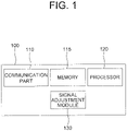
- Fig. 1 is a drawing schematically illustrating a configuration of a computing device performing a method for delivering a steering intention of an autonomous driving module or a driver to a steering apparatus of a subject vehicle more accurately in accordance with one example embodiment of the present disclosure.
- the computing device 100 may include a signal adjustment module 130 to be described later. Processes of input/output and computations of the signal adjustment module 130 may be respectively performed by at least one communication part 110 and at least one processor 120. However, detailed communication schematics between the communication part 110 and the processor 120 are omitted in Fig. 1 .
- a memory 115 may have stored various instructions to be described later, and the processor 120 may execute the instructions stored in the memory 115 and may perform processes of the present disclosure by executing the instructions to be disclosed later.
- Such description of the computing device 100 does not exclude an integrated device including any combination of a processor, a memory, a medium, or any other computing components.
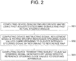
- Fig. 2 is a drawing schematically illustrating a flow of the method for delivering the steering intention of the autonomous driving module or the driver to the steering apparatus of the subject vehicle more accurately in accordance with one example embodiment of the present disclosure.
- the computing device 100 may generate a reference map by using one or more past adjusted steering signals and one or more past actual steered angles. And, at a step of S02, the computing device 100, if a subject intended steering signal is acquired, may instruct the signal adjustment module 130 to find one or more specific reference steering guide values corresponding to the subject intended steering signal by referring to the reference map. Then, at a step of S03, the computing device 100 may transmit a subject adjusted steering signal to the steering apparatus, generated by using the specific reference steering guide values, to thereby support the steering apparatus to rotate the subject vehicle by a specific steering angle corresponding to the subject intended steering signal.
- the method of the present disclosure is directed to a method for ensuring the subject vehicle to be turned as the intention of the autonomous driving module or the driver, even though the steering apparatus of the subject vehicle malfunctions due to internal or external factors, by using the reference map.
- the reference map may be configured as a table.
- Such reference map may be generated by referring to the past adjusted steering signals inputted to the steering apparatus of the subject vehicle and the past actual steered angles which denote real angles of the subject vehicle being actually rotated when the past adjusted steering signals are inputted, included in the past driving records.
- a specific past adjusted steering signal may have been inputted to the steering apparatus to rotate the subject vehicle by 32 degrees but the subject vehicle has been rotated by 30 degrees so that its corresponding specific past actual steered angle may denote a rotation by 30 degrees.
- Such difference between the two angles may have been caused by a breakdown of the steering apparatus.
- the past adjusted steering signals and the past actual steered angles may have been detected and stored during a prescribed time range from a certain past timing to the current timing.
- the past adjusted steering signals may have been detected by analyzing past control signals internally transmitted from the autonomous driving module or the driver, and the past actual steered angles may have been detected by analyzing a motion of the subject vehicle performed during said prescribed time range, through at least one of a computer vision module and a steering detection sensor, which interworks with the computing device 100. More specifically, the past actual steered angles may not be acquired by analyzing internal signals, different from the past adjusted steering signals. That is, those may be acquired by using external sensors such as the computer vision module and the steering detection sensor.
- the computer vision module may interwork with a camera on the subject vehicle and calculate an angle of a rotation of the subject vehicle by analyzing an image acquired through the camera, using a well-known angle calculation schemes.
- the steering detection sensor may be installed on the steering apparatus as a physical external sensor, to detect an angle of a rotation of wheels.
- the past adjusted steering signals and the past actual steered angles may be additionally processed in order to be used for generating the reference map.
- Such additional process may represent a process of finding information on general relationships between reference steering guide values and reference actual steering angles by using the past adjusted steering signals and the past actual steered angles.
- the reference steering guide values may represent signals to be inputted to the steering apparatus, and the reference actual steering angles may represent actual steered angles expected when said signals are inputted thereto.
- the reference steering guide values may denote values to be inputted to the steering apparatus to make the subject vehicle to rotate by their corresponding reference actual steering angles.
- a specific reference actual steering angle of 32 degrees may correspond to a specific reference steering guide value of 30 degrees.
- the reference actual steering angles may have been set by a manager to cover all angles expected to be intended by the autonomous driving module or the driver. As one example, it may have been set as [-60.00, -59.90, -59.80, ... , 59.80,59.90,60.00], covering a range between - 60 degrees and 60 degrees at 0.1 degree intervals. Such range and the intervals may be determined by the manager from the beginning. Otherwise, the reference actual steering angles may be set continuously, not discretely as shown above, but a scope of the present disclosure may not be limited thereto.
- ⁇ pastsignal may denote a first vector including information on the past adjusted steering signals and ⁇ pastangle may denote a second vector including information on the past actual steered angles.
- ⁇ refangle may denote a third vector including information on said prescribed reference actual steering angles, and ⁇ refsignal may denote a fourth vector including information on the reference steering guide values.
- K ( ⁇ 1 , ⁇ 2 ) may denote an output of a kernel function for two input vectors ⁇ 1 and ⁇ 2
- ⁇ n may denote estimated standard deviations of noises of the past actual steered angles.
- the reference steering guide values can be determined by using the formula owing to characteristics of the GP regression.
- the GP regression is a regression operation for estimating a function value of an input x ⁇ R N by using a given data set including information on x i ⁇ R N and its corresponding function values y i ⁇ R M in a form of a probability distribution.
- x i ⁇ R N may correspond to the past actual steered angles
- y i ⁇ R M may correspond to the past adjusted steering signals
- x ⁇ R N may correspond to the reference actual steered angles
- averages of the probability distribution to be used for estimating the function values of the reference actual steered angles may be the reference steering guide values.
- the formula for the GP regression can be deducted from a following formula: ⁇ pastsignal ⁇ refsignal ⁇ N ( ⁇ pastangle ⁇ refangle , K ⁇ pastangle , ⁇ pastangle + ⁇ n 2 I K ⁇ pastangle , ⁇ refangle K ⁇ pastangle , ⁇ refangle K ⁇ refangle , ⁇ refangle
- the computing device 100 may instruct the signal adjustment module 130 to select one or more specific reference steering guide values, among reference steering guide values of the reference map, corresponding to the subject intended steering signal, by referring to the subject intended steering signal corresponding to the specific steering angle.
- the computing device 100 may instruct the signal adjustment module 130 to (i) calculate similarity scores between the reference actual steering angles and the subject intended steering signal by referring to the subject intended steering signal representing the specific steering angle, (ii) find a first to an N-th specific reference actual steering angles corresponding to specific similarity scores which are the top N ones among the similarity scores.
- a specific similarity score may be calculated by (i) comparing a size of the specific steering angle and a size of a specific reference actual steering angle, and (ii) setting one with larger size at a denominator and the other one with smaller size at a numerator. The whole similarity scores may be calculated similarly to the specific similarity score.
- one of the reference steering guide values which is the smallest among ones larger than the specific steering angle may be set as a first specific reference steering guide value, and the other one of the reference steering guide values which is the largest among ones smaller than the specific steering angle may be set as a second specific reference steering guide value.
- the computing device 100 may perform a linear interpolation by referring to the first to the N-th specific reference actual steering angles and their corresponding first to the N-th specific reference steering guide values, to thereby generate the subject adjusted steering signal.
- Fig. 3 will be referred to.
- Fig. 3 is a drawing schematically illustrating how the subject vehicle is rotated by a specific steering angle corresponding to a subject adjusted steering signal, generated from a subject intended steering signal by delivering the steering intention of the autonomous driving module or the driver to the steering apparatus of the subject vehicle more accurately in accordance with one example embodiment of the present disclosure.
- the specific steering angle is 31.84 degrees
- the reference actual steering angles are set as [-60.00, -59.90, -59.80, ... , 59.80, 59.90, 60.00]
- N is two
- the first specific reference steering guide value corresponding to the first specific reference actual steering angle of 31.80 degrees is 33.9 degrees
- the second specific reference steering guide value corresponding to the second specific reference actual steering angle of 31.90 degrees is 34.10 degrees.
- the subject adjusted steering signal for this case may be 33.98 degrees
- the steering apparatus which acquired the subject adjusted steering signal as its input may rotate the subject vehicle by 31.84 degrees.
- the processes corresponding to the steps of S01 and S02 may be performed whenever a trigger corresponding to a start of the subject vehicle is detected.
- the steps of S01 and S02 may be performed whenever the subject vehicle is started.
- the computing device 100 may evaluate the steering apparatus while it generates the reference map. Specifically, the computing device 100 may generate each of steering accuracy scores by referring to each of the reference actual steering angles and its corresponding reference steering guide values.
- each of differences between each of the reference actual steering angles and its corresponding reference steering guide values can be an indicator for a dislocation of the steering apparatus, because the two may be largely different when the steering apparatus has a breakdown.
- the computing device 100 may compare each of the reference actual steering angles and its corresponding reference steering guide values, to thereby generate each of the steering accuracy scores corresponding to each of similarities between each of the reference actual steering angles and its corresponding reference steering guide values.
- the computing device 100 may transmit an alarm to the driver if a ratio of the number of specific steering accuracy scores to the total number of the steering accuracy scores is larger than a first threshold.
- the specific steering accuracy scores, selected among the steering accuracy scores may be smaller than a second threshold. For example, if a ratio of the number of the specific steering accuracy scores which is smaller than 0.95 to the total number is more than 0.1, the alarm may be transmitted.
- the present disclosure has an effect of providing a method for delivering a steering intention of an autonomous driving module or a driver to a steering apparatus of a subject vehicle more accurately, to thereby improve a credibility of an autonomous driving.
- the present disclosure has another of providing a method for generating a reference map to be used for delivering the steering intention of the autonomous driving module or the driver to the steering apparatus of the subject vehicle more accurately.
- the present disclosure has still another effect of alerting the driver to a possible breakdown of the steering apparatus while delivering the steering intention of the autonomous driving module or the driver to the steering apparatus of the subject vehicle more accurately.
- the embodiments of the present disclosure as explained above can be implemented in a form of executable program command through a variety of computer means recordable to computer readable media.
- the computer readable media may include solely or in combination, program commands, data files, and data structures.
- the program commands recorded to the media may be components specially designed for the present disclosure or may be usable to a skilled human in a field of computer software.
- Computer readable media include magnetic media such as hard disk, floppy disk, and magnetic tape, optical media such as CD-ROM and DVD, magneto-optical media such as floptical disk and hardware devices such as ROM, RAM, and flash memory specially designed to store and carry out program commands.
- Program commands include not only a machine language code made by a complier but also a high level code that can be used by an interpreter etc., which is executed by a computer.
- the aforementioned hardware device can work as more than a software module to perform the action of the present disclosure and they can do the same in the opposite case.
Landscapes
- Engineering & Computer Science (AREA)
- Transportation (AREA)
- Mechanical Engineering (AREA)
- Automation & Control Theory (AREA)
- Chemical & Material Sciences (AREA)
- Combustion & Propulsion (AREA)
- Human Computer Interaction (AREA)
- Physics & Mathematics (AREA)
- Evolutionary Computation (AREA)
- Remote Sensing (AREA)
- Health & Medical Sciences (AREA)
- Game Theory and Decision Science (AREA)
- Medical Informatics (AREA)
- Aviation & Aerospace Engineering (AREA)
- Radar, Positioning & Navigation (AREA)
- Artificial Intelligence (AREA)
- Business, Economics & Management (AREA)
- General Physics & Mathematics (AREA)
- Mathematical Physics (AREA)
- Steering Control In Accordance With Driving Conditions (AREA)
- Traffic Control Systems (AREA)
- Control Of Driving Devices And Active Controlling Of Vehicle (AREA)
Claims (13)
- Verfahren zum Übermitteln einer genaueren Lenkabsicht eines autonomen Fahrmoduls oder eines Fahrers an eine Lenkvorrichtung eines betreffenden Fahrzeugs unter Verwendung einer Referenzkarte, die ein Regelsatz ist, der durch Bezugnahme auf frühere Fahraufzeichnungen des betreffenden Fahrzeugs erzeugt wird, mit den Schritten:(a) eine Rechenvorrichtung (100), wenn ein beabsichtigtes Subjekt-Lenksignal, das in einem Subjekt-Steuersignal enthalten ist, das durch das autonome Fahrmodul oder den Fahrer zu einem aktuellen Zeitpunkt eingegeben wird, ein Signalanpassungsmodul (130) anweist, durch Bezugnahme auf die Referenzkarte, die durch Verwendung von vergangenen angepassten Lenksignalen und vergangenen tatsächlichen gelenkten Winkeln, die in den vergangenen Fahraufzeichnungen enthalten sind, erzeugt wird, einen oder mehrere spezifische Referenz-Lenkungsführungswerte unter Referenz-Lenkungsführungswerten der Referenzkarte auszuwählen, die dem beabsichtigten Subjekt-Lenksignal (S02) entsprechen;
und(b) die Rechenvorrichtung (100) (i) das gegenständlich beabsichtigte Lenksignal unter Bezugnahme auf die spezifischen Referenz-Lenkführungswerte einstellt, um ein gegenständlich eingestelltes Lenksignal zu erzeugen, und (ii) das gegenständlich eingestellte Lenksignal an die Lenkvorrichtung überträgt, um dadurch die Lenkvorrichtung zu unterstützen, das gegenständliche Fahrzeug um einen spezifischen Lenkwinkel zu drehen, der dem gegenständlich beabsichtigten Lenksignal entspricht, das von dem autonomen Fahrmodul oder dem Fahrer beabsichtigt worden ist (S03), dadurch gekennzeichnet, dass vor dem Schritt (a) ferner ein Schritt umfasst ist, dass: (a0) die Rechenvorrichtung (100) (i) einen ersten Vektor erzeugt, der Informationen über die in der Vergangenheit eingestellten Lenksignale enthält, einen zweiten Vektor, der Informationen über die in der Vergangenheit tatsächlich gelenkten Winkel enthält, und einen dritten Vektor, der Informationen über vorgeschriebene tatsächliche Referenzlenkwinkel enthält, (ii) eine Regressionsoperation unter Verwendung des ersten, (ii) Durchführen einer Regressionsoperation unter Verwendung des ersten, des zweiten und des dritten Vektors, und (iii) Erzeugen der Referenzkarte, die Informationen über (iii-I) die durch die Regressionsoperation erzeugten Referenz-Lenkungsführungswerte, (iii-2) die tatsächlichen Referenz-Lenkungswinkel und (iii-3) eine Beziehung zwischen den Referenz-Lenkungsführungswerten und den tatsächlichen Referenz-Lenkungswinkeln (sol) enthält. - Verfahren nach Anspruch 1, wobei die Rechenvorrichtung (100) im Schritt (a0) die Regressionsoperation unter Verwendung der folgenden Formel durchführt, um die Referenzlenkführungswerte zu erzeugen:

- Verfahren nach Anspruch 1, wobei die in der Vergangenheit eingestellten Lenksignale unter Verwendung vergangener Steuersignale erfasst wurden, die von dem autonomen Fahrmodul oder dem Fahrer für einen vorgeschriebenen Zeitbereich von einem bestimmten vergangenen Zeitpunkt bis zum aktuellen Zeitpunkt übertragen wurden, und wobei die in der Vergangenheit tatsächlich gelenkten Winkel durch Analysieren einer Bewegung des betreffenden Fahrzeugs erfasst werden, die während des Zeitbereichs durch mindestens ein Computer-Vision-Modul und einen Lenkerfassungssensor durchgeführt wird, der mit der Rechenvorrichtung (100) zusammenwirkt.
- Verfahren nach Anspruch 1, ferner umfassend einen Schritt des:
(al) die Rechenvorrichtung (100) jeden der Lenkgenauigkeitswerte durch Bezugnahme auf jeden der tatsächlichen Referenzlenkwinkel und seine entsprechenden Referenzlenkrichtwerte erzeugt, und durch Bezugnahme auf die Lenkgenauigkeitswerte bestimmt, ob ein Alarm über die Lenkvorrichtung an den Fahrer übermittelt werden soll oder nicht. - Verfahren nach Anspruch 4, wobei im Schritt (al) die Rechenvorrichtung (100) die Größen jedes der tatsächlichen Referenzlenkwinkel und seiner entsprechenden Referenzienkführungswerte vergleicht, um dadurch jede der Lenkgenauigkeitspunkte zu erzeugen, die jeder der Ähnlichkeiten zwischen jedem der tatsächlichen Referenzlenkwinkel und seinen entsprechenden Referenz-Lenkungsführungswerten entspricht, und überträgt den Alarm, wenn ein Verhältnis der Anzahl spezifischer Lenkgenauigkeitswerte zur Gesamtzahl der Lenkgenauigkeitswerte größer als ein erster Schwellenwert ist, wobei die spezifischen Lenkgenauigkeitswerte, die aus den Lenkgenauigkeitswerten ausgewählt werden, kleiner als ein zweiter Schwellenwert sind.
- Verfahren nach Anspruch 4, wobei die Rechenvorrichtung (100) Prozesse entsprechend den Schritten (aO) und (al) durchführt, wenn ein Auslöser, der einem Start des betreffenden Fahrzeugs entspricht, erkannt wird.
- Verfahren zum genaueren Übermitteln einer Lenkabsicht eines autonomen Fahrmoduls oder eines Fahrers an eine Lenkvorrichtung eines betreffenden Fahrzeugs unter Verwendung einer Referenzkarte, die ein Regelsatz ist, der durch Bezugnahme auf frühere Fahraufzeichnungen des betreffenden Fahrzeugs erzeugt wird, mit den folgenden Schritten:(a) eine Rechenvorrichtung (100), wenn ein beabsichtigtes Subjekt-Lenksignal, das in einem Subjekt-Steuersignal enthalten ist, das durch das autonome Fahrmodul oder den Fahrer zu einem aktuellen Zeitpunkt eingegeben wird, ein Signalanpassungsmodul (130) anweist, durch Bezugnahme auf die Referenzkarte, die durch Verwendung von früheren angepassten Lenksignalen und früheren tatsächlichen gelenkten Winkeln, die in den früheren Fahraufzeichnungen enthalten sind, erzeugt wird, einen oder mehrere spezifische Referenz-Lenkungsführungswerte unter Referenz-Lenkungsführungswerten der Referenzkarte auszuwählen, die dem beabsichtigten Subjekt-Lenksignal (S02) entsprechen; und(b) die Rechenvorrichtung (100) (i) das vom Subjekt beabsichtigte Lenksignal unter Bezugnahme auf die spezifischen Referenzlenkführungswerte anpasst, um ein vom Subjekt angepasstes Lenksignal zu erzeugen, und (ii) das vom Subjekt angepasste Lenksignal an die Lenkvorrichtung überträgt, um dadurch die Lenkvorrichtung zu unterstützen, das Subjektfahrzeug um einen spezifischen Lenkwinkel zu drehen, der dem vom Subjekt beabsichtigten Lenksignal entspricht, das von dem autonomen Fahrmodul oder dem Fahrer (S03) beabsichtigt wurde, dadurch gekennzeichnet, dass bei dem Schritt (a) die Rechenvorrichtung (100) das Signalanpassungsmodul (130) anweist, (i) Ähnlichkeitsbewertungen zwischen den tatsächlichen Referenzlenkwinkeln und dem beabsichtigten Subjekt-Lenksignal zu berechnen, indem auf das beabsichtigte Subjekt-Lenksignal Bezug genommen wird, das den spezifischen Lenkwinkel darstellt, (ii) einen ersten bis einen N-ten spezifischen tatsächlichen Referenzlenkwinkel zu finden, der spezifischen Ähnlichkeitsbewertungen entspricht, die die obersten N unter den Ähnlichkeitsbewertungen sind, und (iii) einen ersten bis einen N-ten spezifischen Referenzlenkführungswert zu finden, der dem ersten bis dem N-ten spezifischen tatsächlichen Referenzlenkwinkel entspricht, indem auf Informationen über Beziehungen zwischen den tatsächlichen Referenzlenkwinkeln und ihren entsprechenden Referenzlenkführungswerten Bezug genommen wird, und wobei bei dem Schritt (b) die Rechenvorrichtung (100) eine lineare Interpolation unter Bezugnahme auf die ersten bis N-ten spezifischen tatsächlichen Referenzlenkwinkel und ihre entsprechenden ersten bis N-ten spezifischen Referenzlenkführungswerte durchführt, um dadurch das betreffende angepasste Lenksignal zu erzeugen.
- eine Rechenvorrichtung (100) zum genaueren Übermitteln einer Lenkabsicht eines autonomen Fahrmoduls oder eines Fahrers an eine Lenkvorrichtung eines betreffenden Fahrzeugs unter Verwendung einer Referenzkarte, bei der es sich um einen Regelsatz handelt, der durch Bezugnahme auf frühere Fahraufzeichnungen des betreffenden Fahrzeugs erzeugt wurde, mit:mindestens einen Speicher (115), der Befehle speichert; und mindestens einen Prozessor (120), der so konfiguriert ist, dass er die Befehle ausführt, um die folgenden Prozesse durchzuführen: (I) wenn ein beabsichtigtes Subjekt-Lenksignal,das in einem Subjekt-Steuersignal enthalten ist, das durch das autonome Fahrmodul oder den Fahrer zu einem aktuellen Zeitpunkt eingegeben wird, ein Signalanpassungsmodul (130) anweist, unter Bezugnahme auf die Referenzkarte,die durch Verwendung von vergangenen angepassten Lenksignalen undvergangenen tatsächlichen Lenkwinkeln, die in den vergangenen Fahraufzeichnungen enthalten sind, erzeugt wird, einen oder mehrere spezifische Referenz-Lenkführungswerte unter Referenz-Lenkführungswerten der Referenzkarte auszuwählen, die dem beabsichtigten Subjekt-Lenksignal (S02) entsprechen; und (II) (i) Anpassen des beabsichtigten Subjekt-Lenksignals durch Bezugnahme auf die spezifischen Referenz-Lenkungsführungswerte, um ein angepasstes Subjekt-Lenksignal zu erzeugen, und (ii) Übertragen des angepassten Subjekt-Lenksignals an die Lenkvorrichtung, um dadurch die Lenkvorrichtung zu unterstützen, das Subjekt-Fahrzeug um einen spezifischen Lenkwinkel zu lenken, der dem beabsichtigten Lenkungssignal entspricht, das von dem autonomen Fahrmodul oderdem Fahrer beabsichtigt wurde (S03),dadurch gekennzeichnet, dass der Prozessor (120) vor dem Prozess von (I) weiterhin einen Prozess durchführt, bei dem:
(10) (i) Erzeugen eines ersten Vektors, der Informationen über die in der Vergangenheit eingestellten Lenksignale enthält, eines zweiten Vektors, der Informationen über die in der Vergangenheit tatsächlich gelenkten Winkel enthält, und eines dritten Vektors, der Informationen über vorgeschriebene tatsächliche Referenzlenkwinkel enthält, (ii) Durchführen einer Regressionsoperation unter Verwendung des ersten, des zweiten, und des dritten Vektors, und (iii) Erzeugen der Referenzkarte mit Informationen über (iii-I) die durch die Regressionsoperation erzeugten Referenzlenkführungswerte, (iii-2) die tatsächlichen Referenzlenkwinkel und (iii-3) eine Beziehung zwischen den Referenzlenkführungswerten und den tatsächlichen Referenzlenkwinkeln (SOI). - Rechenvorrichtung (100) nach Anspruch 8, wobei der Prozessor (120) bei dem Verfahren nach (10) die Regressionsoperation unter Verwendung einer folgenden Formel durchführt, um die Referenzlenkführungswerte zu erzeugen:

- Rechenvorrichtung (100) nach Anspruch 8, wobei die in der Vergangenheit eingestellten Lenksignale unter Verwendung von Steuersignalen aus der Vergangenheit, die von dem autonomen Fahrmodul oder dem Fahrer für einen vorgeschriebenen Zeitbereich von einem bestimmten Zeitpunkt in der Vergangenheit bis zum aktuellen Zeitpunkt übertragen wurden, erfasst wurden, und wobei die tatsächlichen Lenkwinkel aus der Vergangenheit
gelenkten Winkel durch Analysieren einer Bewegung des betreffenden Fahrzeugs, die während des genannten Zeitbereichs durchgeführt wurde, durch mindestens eine der folgenden Methoden gewonnen werden: Computer Vision Modul und/oder einen Lenkungserfassungssensor, der mit der Rechenvorrichtung (100) zusammenarbeitet. - Rechenvorrichtung (100) nach Anspruch 8, wobei der Prozessor (120) ferner einen Prozess durchführt, bei dem:
(II) Erzeugen jeder der Lenkgenauigkeitsbewertungen durch Bezugnahme auf jeden der tatsächlichen Referenzlenkwinkel und seiner entsprechenden Referenzlenkführungswerte, und Bestimmen, ob ein Alarm über die Lenkvorrichtung an den Fahrer übertragen werden soll oder nicht, durch Bezugnahme auf die Lenkgenauigkeitsbewertungen. - Rechenvorrichtung (100) nach Anspruch 11, wobei der Prozessor (120) bei dem Verfahren von (II) Größen jedes der tatsächlichen Referenzlenkwinkel und seiner entsprechenden Referenzlenkführungswerte vergleicht, um dadurch jede der Lenkgenauigkeitspunkte zu erzeugen, die jeder von Ähnlichkeiten zwischen jedem der tatsächlichen Referenzlenkwinkel und seinen entsprechenden Referenzlenkführungswerten entspricht, und überträgt den Alarm, wenn ein Verhältnis der Anzahl spezifischer Lenkgenauigkeitswerte zu der Gesamtzahl der Lenkgenauigkeitswerte größer als ein erster Schwellenwert ist, wobei die spezifischen Lenkgenauigkeitswerte, die aus den Lenkgenauigkeitswerten ausgewählt werden, kleiner als ein zweiter Schwellenwert sind.
- Eine Rechenvorrichtung (100) zum genaueren Übermitteln einer Lenkabsicht eines autonomen Fahrmoduls oder eines Fahrers an eine Lenkvorrichtung eines Fahrzeugs unter Verwendung einer Referenzkarte, die ein Regelsatz ist, der durch Bezugnahme auf vergangene Fahraufzeichnungen des betreffenden Fahrzeugs erzeugt wird, mit:mindestens einen Speicher (115), der Anweisungen speichert; und mindestens einen Prozessor (120), der so konfiguriert ist, dass er die Anweisungen ausführt, um folgende Prozesse durchzuführen (I) wenn ein beabsichtigtes Subjekt-Lenksignal, das in einem Subjekt-Steuersignal enthalten ist, das durch das autonome Fahrmodul oder den Fahrer zu einem aktuellen Zeitpunkt eingegeben wird, ein Signalanpassungsmodul (130) anweist, unter Bezugnahme auf die Referenzkarte,die durch Verwendung von in der Vergangenheit angepassten Lenksignalen und in der Vergangenheit tatsächlich gelenkten Winkeln, die in den vergangenen Fahrdaten enthalten sind, erzeugt wird, einen oder mehrere spezifischeReferenzlenkungsführungswerte unter den Referenzlenkungsführungswerten der Referenzkarte auszuwählen, die dem beabsichtigten Lenksignal (S02) des Subjekts entsprechen; und (II) (i) das beabsichtigte Lenksignal des Subjekts unter Bezugnahme auf die spezifischen Referenzlenkungsführungswerte einzustellen, um ein eingestelltes Lenksignal des Subjekts zu erzeugen, und (ii) das eingestellte Lenksignal des Subjekts an die Lenkvorrichtung zu übertragen, um dadurch die Lenkvorrichtung zu unterstützen, das Fahrzeug des Subjekts um einen spezifischen Lenkwinkel zu drehen, der dem beabsichtigten Lenksignal des Subjekts entspricht,das von dem autonomen Fahrmodul oder dem Fahrer beabsichtigt worden ist (S03),dadurch gekennzeichnet, dass bei dem Verfahren von (I) der Prozessor (120) das Signalanpassungsmodul (130) anweist, (i) Ähnlichkeitswerte zwischen den tatsächlichen Referenzlenkwinkeln und dem beabsichtigten Subjekt-Lenksignal zu berechnen, indem auf das beabsichtigte Subjekt-Lenksignal Bezug genommen wird,das den spezifischen Lenkwinkel darstellt, (ii) einen ersten bis einen N-ten spezifischen tatsächlichen Referenzlenkwinkel zu finden, der spezifischen Ähnlichkeitswerten entspricht, die die obersten N unter den Ähnlichkeitswerten sind und (iii) Finden eines ersten bis N-ten spezifischen Referenz-Lenkungsführungswertes, der dem ersten bis N-ten spezifischen Referenz-Ist-Lenkungswinkel entspricht, durch Bezugnahme auf Informationen über Beziehungen zwischen den Referenz-Ist-Lenkungswinkeln und ihren entsprechenden Referenz-Lenkungsführungswerten, und wobei bei dem Verfahren von (II) der Prozessor (120) eine lineare Interpolation durch Bezugnahme auf den ersten bis N-ten spezifischen Referenz-Ist-Lenkungswinkel und ihre entsprechenden ersten bis N-ten spezifischen Referenz-Lenkungsführungswerte durchführt, um dadurch das angepasste Subjekt-Lenksignal zu erzeugen.
Applications Claiming Priority (2)
| Application Number | Priority Date | Filing Date | Title |
|---|---|---|---|
| US201962799407P | 2019-01-31 | 2019-01-31 | |
| US16/740,213 US10843728B2 (en) | 2019-01-31 | 2020-01-10 | Method and device for delivering steering intention of autonomous driving module or driver to steering apparatus of subject vehicle more accurately |
Publications (2)
| Publication Number | Publication Date |
|---|---|
| EP3689708A1 EP3689708A1 (de) | 2020-08-05 |
| EP3689708B1 true EP3689708B1 (de) | 2022-06-01 |
Family
ID=69187607
Family Applications (1)
| Application Number | Title | Priority Date | Filing Date |
|---|---|---|---|
| EP20153038.3A Active EP3689708B1 (de) | 2019-01-31 | 2020-01-22 | Verfahren und vorrichtung zur genaueren bereitstellung einer lenkabsicht eines autonomen antriebsmoduls oder eines fahrers an eine lenkvorrichtung eines personenfahrzeugs |
Country Status (5)
| Country | Link |
|---|---|
| US (1) | US10843728B2 (de) |
| EP (1) | EP3689708B1 (de) |
| JP (1) | JP6921443B2 (de) |
| KR (1) | KR102280417B1 (de) |
| CN (1) | CN111497939B (de) |
Families Citing this family (2)
| Publication number | Priority date | Publication date | Assignee | Title |
|---|---|---|---|---|
| CN113891048B (zh) * | 2021-10-28 | 2022-11-15 | 江苏濠汉信息技术有限公司 | 一种轨道机车超视距影像图传系统 |
| KR20250046831A (ko) * | 2023-09-27 | 2025-04-03 | 에이치엘만도 주식회사 | 차로 유지 보조 시스템의 이상 감지 방법 및 장치 |
Family Cites Families (38)
| Publication number | Priority date | Publication date | Assignee | Title |
|---|---|---|---|---|
| JPS6032043B2 (ja) * | 1977-06-03 | 1985-07-25 | 三輪精機株式会社 | 多段速油圧駆動装置 |
| JP2715555B2 (ja) * | 1989-06-13 | 1998-02-18 | トヨタ自動車株式会社 | 車両用ステアリング連動前照灯システム |
| JPH08282510A (ja) * | 1995-04-17 | 1996-10-29 | Koyo Seiko Co Ltd | パワーステアリング装置 |
| JP5135722B2 (ja) * | 2006-06-19 | 2013-02-06 | 株式会社ジェイテクト | 車両用操舵装置 |
| JP5086582B2 (ja) * | 2006-08-09 | 2012-11-28 | 本田技研工業株式会社 | 操舵制御システムおよび操舵制御プログラム |
| JP4539693B2 (ja) * | 2007-08-27 | 2010-09-08 | トヨタ自動車株式会社 | 操舵制御装置及び車両 |
| DE102008002699A1 (de) * | 2008-06-27 | 2009-12-31 | Robert Bosch Gmbh | Vorrichtung und Verfahren zum Steuern einer automatischen Lenkung eines Fahrzeugs und Vorrichtung und Verfahren zum Überprüfen einer Ausführbarkeit einer vorgegebenen Soll-Fahrtrichtungsgröße für ein Fahrzeug |
| US8880316B2 (en) * | 2010-04-14 | 2014-11-04 | Toyota Jidosha Kabushiki Kaisha | Control apparatus for vehicle |
| JP5893498B2 (ja) * | 2012-04-26 | 2016-03-23 | 日立オートモティブシステムズステアリング株式会社 | パワーステアリング装置およびパワーステアリング装置の制御装置 |
| CN104736416B (zh) * | 2012-10-04 | 2016-08-24 | 日产自动车株式会社 | 转轮控制装置 |
| EP2918479B1 (de) * | 2012-11-07 | 2019-06-12 | Nissan Motor Co., Ltd. | Lenksteuerungsvorrichtung |
| KR102002334B1 (ko) * | 2012-11-20 | 2019-07-23 | 현대모비스 주식회사 | 차선 유지 제어 장치 |
| JP6032043B2 (ja) * | 2013-02-13 | 2016-11-24 | 日産自動車株式会社 | 車両用操舵制御装置及び車両用操舵制御方法 |
| JP5867648B2 (ja) * | 2013-02-21 | 2016-02-24 | 日産自動車株式会社 | 車両用操舵制御装置及び車両用操舵制御方法 |
| JP6142659B2 (ja) * | 2013-05-13 | 2017-06-07 | 日産自動車株式会社 | 車両用操舵制御装置及び車両用操舵制御方法 |
| JP5530020B1 (ja) * | 2013-11-01 | 2014-06-25 | 株式会社日立パワーソリューションズ | 異常診断システム及び異常診断方法 |
| JP6322023B2 (ja) * | 2014-03-28 | 2018-05-09 | 株式会社Subaru | 計測装置、及びそれを用いた故障診断装置 |
| JP2016222180A (ja) * | 2015-06-02 | 2016-12-28 | 富士重工業株式会社 | 車両操舵制御装置 |
| JP2017077830A (ja) * | 2015-10-21 | 2017-04-27 | Kyb株式会社 | 電動パワーステアリング装置 |
| JP6198181B2 (ja) * | 2015-11-06 | 2017-09-20 | マツダ株式会社 | 車両用挙動制御装置 |
| WO2018008628A1 (ja) * | 2016-07-05 | 2018-01-11 | 日本精工株式会社 | 検出装置及び電動パワーステアリング装置 |
| JP6270251B1 (ja) * | 2016-09-21 | 2018-01-31 | マツダ株式会社 | 車両用挙動制御装置 |
| CN109891472B (zh) * | 2016-11-09 | 2021-11-26 | 本田技研工业株式会社 | 车辆控制系统、车辆控制方法及存储介质 |
| US9874871B1 (en) * | 2016-11-21 | 2018-01-23 | Baidu Usa Llc | Method to dynamically adjusting steering rates of autonomous vehicles |
| CN116653715B (zh) * | 2017-03-29 | 2025-08-12 | 提爱思科技股份有限公司 | 车辆控制系统 |
| US10315691B2 (en) * | 2017-03-30 | 2019-06-11 | Ford Global Technologies, Llc | Methods and apparatus to correct clear vision errors in a vehicle steering system |
| US10569784B2 (en) * | 2017-09-28 | 2020-02-25 | Waymo Llc | Detecting and responding to propulsion and steering system errors for autonomous vehicles |
| US10591914B2 (en) * | 2017-11-08 | 2020-03-17 | GM Global Technology Operations LLC | Systems and methods for autonomous vehicle behavior control |
| US10845803B2 (en) * | 2017-11-29 | 2020-11-24 | Nio Usa, Inc. | Method and apparatus for simultaneous processing and logging of automotive vision system with controls and fault monitoring |
| US20190163176A1 (en) * | 2017-11-30 | 2019-05-30 | drive.ai Inc. | Method for transferring control of an autonomous vehicle to a remote operator |
| US11525688B2 (en) * | 2017-12-15 | 2022-12-13 | Samsung Electronics Co., Ltd. | Method and apparatus for determining object position |
| US20190185010A1 (en) * | 2017-12-18 | 2019-06-20 | PlusAI Corp | Method and system for self capability aware route planning in autonomous driving vehicles |
| US11126199B2 (en) * | 2018-04-16 | 2021-09-21 | Baidu Usa Llc | Learning based speed planner for autonomous driving vehicles |
| US10908609B2 (en) * | 2018-04-30 | 2021-02-02 | Toyota Research Institute, Inc. | Apparatus and method for autonomous driving |
| US20180348771A1 (en) * | 2018-07-26 | 2018-12-06 | GM Global Technology Operations LLC | Stop contingency planning during autonomous vehicle operation |
| US10976748B2 (en) * | 2018-08-22 | 2021-04-13 | Waymo Llc | Detecting and responding to sounds for autonomous vehicles |
| US11280625B2 (en) * | 2018-09-07 | 2022-03-22 | Waymo Llc | Ambient lighting conditions for autonomous vehicles |
| US11535262B2 (en) * | 2018-09-10 | 2022-12-27 | Here Global B.V. | Method and apparatus for using a passenger-based driving profile |
-
2020
- 2020-01-10 US US16/740,213 patent/US10843728B2/en active Active
- 2020-01-20 KR KR1020200007633A patent/KR102280417B1/ko active Active
- 2020-01-20 CN CN202010064861.1A patent/CN111497939B/zh active Active
- 2020-01-22 EP EP20153038.3A patent/EP3689708B1/de active Active
- 2020-01-27 JP JP2020011165A patent/JP6921443B2/ja active Active
Also Published As
| Publication number | Publication date |
|---|---|
| CN111497939A (zh) | 2020-08-07 |
| JP2020125107A (ja) | 2020-08-20 |
| CN111497939B (zh) | 2022-12-06 |
| US10843728B2 (en) | 2020-11-24 |
| KR20200095380A (ko) | 2020-08-10 |
| JP6921443B2 (ja) | 2021-08-18 |
| KR102280417B1 (ko) | 2021-07-23 |
| US20200247469A1 (en) | 2020-08-06 |
| EP3689708A1 (de) | 2020-08-05 |
Similar Documents
| Publication | Publication Date | Title |
|---|---|---|
| US12287210B2 (en) | Vehicle position estimation device, vehicle position estimation method, and computer-readable recording medium for storing computer program programmed to perform said method | |
| US11188089B2 (en) | Localization for autonomous vehicles using gaussian mixture models | |
| US11740093B2 (en) | Lane marking localization and fusion | |
| US10748032B1 (en) | Method for providing robust object distance estimation based on camera by performing pitch calibration of camera more precisely with fusion of information acquired through camera and information acquired through V2V communication and device using the same | |
| US10803333B2 (en) | Method and device for ego-vehicle localization to update HD map by using V2X information fusion | |
| US9411035B2 (en) | Method and electronic apparatus for angle estimation verification | |
| US20170345312A1 (en) | Apparatus for monitoring adjacent lanes | |
| US10635915B1 (en) | Method and device for warning blind spot cooperatively based on V2V communication with fault tolerance and fluctuation robustness in extreme situation | |
| US11477567B2 (en) | Method and system for locating an acoustic source relative to a vehicle | |
| DE102019216989B4 (de) | Fahrzeugsensorvalidierungssystem und Verfahren zur Objektvalidierung | |
| US11703344B2 (en) | Landmark location estimation apparatus and method, and computer-readable recording medium storing computer program programmed to perform method | |
| US20200252550A1 (en) | Method for correcting misalignment of camera by selectively using information generated by itself and information generated by other entities and device using the same | |
| CN110617815B (zh) | 一种自动驾驶监控告警的方法和装置 | |
| EP3689708B1 (de) | Verfahren und vorrichtung zur genaueren bereitstellung einer lenkabsicht eines autonomen antriebsmoduls oder eines fahrers an eine lenkvorrichtung eines personenfahrzeugs | |
| US12188773B2 (en) | Apparatus and method for determining of correction information of vehicle sensor | |
| US20240116506A1 (en) | Control calculation apparatus and control calculation method | |
| CN116767224B (zh) | 确定可行驶区域的方法、装置、车辆、及存储介质 | |
| US12320902B2 (en) | Spoofing detection for vehicle-based GNSS receivers | |
| EP4252202B1 (de) | Strassenmarkierungserkennung | |
| CN115060252B (zh) | 车辆定位方法 | |
| US12221120B2 (en) | Method and device for monitoring operations of an automated driving system of a vehicle | |
| Patil et al. | Assessing resilience in lane detection methods: Infrastructure-Based sensors and traditional approaches for autonomous vehicles | |
| US20250370141A1 (en) | Method and Device for Improved Positioning of an Ego Vehicle Using a 3D Object Recognition Module | |
| WO2021199555A1 (ja) | 走路生成装置、方法及びプログラム | |
| Riley et al. | Constraint Decision Optimization Model for Safe Autonomous Vehicle Operation |
Legal Events
| Date | Code | Title | Description |
|---|---|---|---|
| PUAI | Public reference made under article 153(3) epc to a published international application that has entered the european phase |
Free format text: ORIGINAL CODE: 0009012 |
|
| STAA | Information on the status of an ep patent application or granted ep patent |
Free format text: STATUS: REQUEST FOR EXAMINATION WAS MADE |
|
| 17P | Request for examination filed |
Effective date: 20200122 |
|
| AK | Designated contracting states |
Kind code of ref document: A1 Designated state(s): AL AT BE BG CH CY CZ DE DK EE ES FI FR GB GR HR HU IE IS IT LI LT LU LV MC MK MT NL NO PL PT RO RS SE SI SK SM TR |
|
| AX | Request for extension of the european patent |
Extension state: BA ME |
|
| RBV | Designated contracting states (corrected) |
Designated state(s): AL AT BE BG CH CY CZ DE DK EE ES FI FR GB GR HR HU IE IS IT LI LT LU LV MC MK MT NL NO PL PT RO RS SE SI SK SM TR |
|
| GRAP | Despatch of communication of intention to grant a patent |
Free format text: ORIGINAL CODE: EPIDOSNIGR1 |
|
| STAA | Information on the status of an ep patent application or granted ep patent |
Free format text: STATUS: GRANT OF PATENT IS INTENDED |
|
| INTG | Intention to grant announced |
Effective date: 20220127 |
|
| GRAS | Grant fee paid |
Free format text: ORIGINAL CODE: EPIDOSNIGR3 |
|
| GRAA | (expected) grant |
Free format text: ORIGINAL CODE: 0009210 |
|
| STAA | Information on the status of an ep patent application or granted ep patent |
Free format text: STATUS: THE PATENT HAS BEEN GRANTED |
|
| AK | Designated contracting states |
Kind code of ref document: B1 Designated state(s): AL AT BE BG CH CY CZ DE DK EE ES FI FR GB GR HR HU IE IS IT LI LT LU LV MC MK MT NL NO PL PT RO RS SE SI SK SM TR |
|
| REG | Reference to a national code |
Ref country code: GB Ref legal event code: FG4D |
|
| REG | Reference to a national code |
Ref country code: AT Ref legal event code: REF Ref document number: 1495214 Country of ref document: AT Kind code of ref document: T Effective date: 20220615 Ref country code: CH Ref legal event code: EP Ref country code: DE Ref legal event code: R096 Ref document number: 602020003302 Country of ref document: DE |
|
| REG | Reference to a national code |
Ref country code: IE Ref legal event code: FG4D |
|
| REG | Reference to a national code |
Ref country code: LT Ref legal event code: MG9D |
|
| REG | Reference to a national code |
Ref country code: NL Ref legal event code: MP Effective date: 20220601 |
|
| PG25 | Lapsed in a contracting state [announced via postgrant information from national office to epo] |
Ref country code: SE Free format text: LAPSE BECAUSE OF FAILURE TO SUBMIT A TRANSLATION OF THE DESCRIPTION OR TO PAY THE FEE WITHIN THE PRESCRIBED TIME-LIMIT Effective date: 20220601 Ref country code: NO Free format text: LAPSE BECAUSE OF FAILURE TO SUBMIT A TRANSLATION OF THE DESCRIPTION OR TO PAY THE FEE WITHIN THE PRESCRIBED TIME-LIMIT Effective date: 20220901 Ref country code: LT Free format text: LAPSE BECAUSE OF FAILURE TO SUBMIT A TRANSLATION OF THE DESCRIPTION OR TO PAY THE FEE WITHIN THE PRESCRIBED TIME-LIMIT Effective date: 20220601 Ref country code: HR Free format text: LAPSE BECAUSE OF FAILURE TO SUBMIT A TRANSLATION OF THE DESCRIPTION OR TO PAY THE FEE WITHIN THE PRESCRIBED TIME-LIMIT Effective date: 20220601 Ref country code: GR Free format text: LAPSE BECAUSE OF FAILURE TO SUBMIT A TRANSLATION OF THE DESCRIPTION OR TO PAY THE FEE WITHIN THE PRESCRIBED TIME-LIMIT Effective date: 20220902 Ref country code: FI Free format text: LAPSE BECAUSE OF FAILURE TO SUBMIT A TRANSLATION OF THE DESCRIPTION OR TO PAY THE FEE WITHIN THE PRESCRIBED TIME-LIMIT Effective date: 20220601 Ref country code: ES Free format text: LAPSE BECAUSE OF FAILURE TO SUBMIT A TRANSLATION OF THE DESCRIPTION OR TO PAY THE FEE WITHIN THE PRESCRIBED TIME-LIMIT Effective date: 20220601 Ref country code: BG Free format text: LAPSE BECAUSE OF FAILURE TO SUBMIT A TRANSLATION OF THE DESCRIPTION OR TO PAY THE FEE WITHIN THE PRESCRIBED TIME-LIMIT Effective date: 20220901 |
|
| REG | Reference to a national code |
Ref country code: AT Ref legal event code: MK05 Ref document number: 1495214 Country of ref document: AT Kind code of ref document: T Effective date: 20220601 |
|
| PG25 | Lapsed in a contracting state [announced via postgrant information from national office to epo] |
Ref country code: RS Free format text: LAPSE BECAUSE OF FAILURE TO SUBMIT A TRANSLATION OF THE DESCRIPTION OR TO PAY THE FEE WITHIN THE PRESCRIBED TIME-LIMIT Effective date: 20220601 Ref country code: PL Free format text: LAPSE BECAUSE OF FAILURE TO SUBMIT A TRANSLATION OF THE DESCRIPTION OR TO PAY THE FEE WITHIN THE PRESCRIBED TIME-LIMIT Effective date: 20220601 Ref country code: LV Free format text: LAPSE BECAUSE OF FAILURE TO SUBMIT A TRANSLATION OF THE DESCRIPTION OR TO PAY THE FEE WITHIN THE PRESCRIBED TIME-LIMIT Effective date: 20220601 |
|
| PG25 | Lapsed in a contracting state [announced via postgrant information from national office to epo] |
Ref country code: NL Free format text: LAPSE BECAUSE OF FAILURE TO SUBMIT A TRANSLATION OF THE DESCRIPTION OR TO PAY THE FEE WITHIN THE PRESCRIBED TIME-LIMIT Effective date: 20220601 |
|
| PG25 | Lapsed in a contracting state [announced via postgrant information from national office to epo] |
Ref country code: SM Free format text: LAPSE BECAUSE OF FAILURE TO SUBMIT A TRANSLATION OF THE DESCRIPTION OR TO PAY THE FEE WITHIN THE PRESCRIBED TIME-LIMIT Effective date: 20220601 Ref country code: SK Free format text: LAPSE BECAUSE OF FAILURE TO SUBMIT A TRANSLATION OF THE DESCRIPTION OR TO PAY THE FEE WITHIN THE PRESCRIBED TIME-LIMIT Effective date: 20220601 Ref country code: RO Free format text: LAPSE BECAUSE OF FAILURE TO SUBMIT A TRANSLATION OF THE DESCRIPTION OR TO PAY THE FEE WITHIN THE PRESCRIBED TIME-LIMIT Effective date: 20220601 Ref country code: PT Free format text: LAPSE BECAUSE OF FAILURE TO SUBMIT A TRANSLATION OF THE DESCRIPTION OR TO PAY THE FEE WITHIN THE PRESCRIBED TIME-LIMIT Effective date: 20221003 Ref country code: EE Free format text: LAPSE BECAUSE OF FAILURE TO SUBMIT A TRANSLATION OF THE DESCRIPTION OR TO PAY THE FEE WITHIN THE PRESCRIBED TIME-LIMIT Effective date: 20220601 Ref country code: CZ Free format text: LAPSE BECAUSE OF FAILURE TO SUBMIT A TRANSLATION OF THE DESCRIPTION OR TO PAY THE FEE WITHIN THE PRESCRIBED TIME-LIMIT Effective date: 20220601 Ref country code: AT Free format text: LAPSE BECAUSE OF FAILURE TO SUBMIT A TRANSLATION OF THE DESCRIPTION OR TO PAY THE FEE WITHIN THE PRESCRIBED TIME-LIMIT Effective date: 20220601 |
|
| PG25 | Lapsed in a contracting state [announced via postgrant information from national office to epo] |
Ref country code: IS Free format text: LAPSE BECAUSE OF FAILURE TO SUBMIT A TRANSLATION OF THE DESCRIPTION OR TO PAY THE FEE WITHIN THE PRESCRIBED TIME-LIMIT Effective date: 20221001 |
|
| REG | Reference to a national code |
Ref country code: DE Ref legal event code: R097 Ref document number: 602020003302 Country of ref document: DE |
|
| PG25 | Lapsed in a contracting state [announced via postgrant information from national office to epo] |
Ref country code: AL Free format text: LAPSE BECAUSE OF FAILURE TO SUBMIT A TRANSLATION OF THE DESCRIPTION OR TO PAY THE FEE WITHIN THE PRESCRIBED TIME-LIMIT Effective date: 20220601 |
|
| PLBE | No opposition filed within time limit |
Free format text: ORIGINAL CODE: 0009261 |
|
| STAA | Information on the status of an ep patent application or granted ep patent |
Free format text: STATUS: NO OPPOSITION FILED WITHIN TIME LIMIT |
|
| PG25 | Lapsed in a contracting state [announced via postgrant information from national office to epo] |
Ref country code: DK Free format text: LAPSE BECAUSE OF FAILURE TO SUBMIT A TRANSLATION OF THE DESCRIPTION OR TO PAY THE FEE WITHIN THE PRESCRIBED TIME-LIMIT Effective date: 20220601 |
|
| 26N | No opposition filed |
Effective date: 20230302 |
|
| PG25 | Lapsed in a contracting state [announced via postgrant information from national office to epo] |
Ref country code: SI Free format text: LAPSE BECAUSE OF FAILURE TO SUBMIT A TRANSLATION OF THE DESCRIPTION OR TO PAY THE FEE WITHIN THE PRESCRIBED TIME-LIMIT Effective date: 20220601 |
|
| P01 | Opt-out of the competence of the unified patent court (upc) registered |
Effective date: 20230522 |
|
| REG | Reference to a national code |
Ref country code: CH Ref legal event code: PL |
|
| PG25 | Lapsed in a contracting state [announced via postgrant information from national office to epo] |
Ref country code: LU Free format text: LAPSE BECAUSE OF NON-PAYMENT OF DUE FEES Effective date: 20230122 |
|
| REG | Reference to a national code |
Ref country code: BE Ref legal event code: MM Effective date: 20230131 |
|
| PG25 | Lapsed in a contracting state [announced via postgrant information from national office to epo] |
Ref country code: LI Free format text: LAPSE BECAUSE OF NON-PAYMENT OF DUE FEES Effective date: 20230131 Ref country code: CH Free format text: LAPSE BECAUSE OF NON-PAYMENT OF DUE FEES Effective date: 20230131 |
|
| PG25 | Lapsed in a contracting state [announced via postgrant information from national office to epo] |
Ref country code: BE Free format text: LAPSE BECAUSE OF NON-PAYMENT OF DUE FEES Effective date: 20230131 |
|
| PG25 | Lapsed in a contracting state [announced via postgrant information from national office to epo] |
Ref country code: IT Free format text: LAPSE BECAUSE OF FAILURE TO SUBMIT A TRANSLATION OF THE DESCRIPTION OR TO PAY THE FEE WITHIN THE PRESCRIBED TIME-LIMIT Effective date: 20220601 Ref country code: IE Free format text: LAPSE BECAUSE OF NON-PAYMENT OF DUE FEES Effective date: 20230122 |
|
| PG25 | Lapsed in a contracting state [announced via postgrant information from national office to epo] |
Ref country code: MC Free format text: LAPSE BECAUSE OF FAILURE TO SUBMIT A TRANSLATION OF THE DESCRIPTION OR TO PAY THE FEE WITHIN THE PRESCRIBED TIME-LIMIT Effective date: 20220601 |
|
| PG25 | Lapsed in a contracting state [announced via postgrant information from national office to epo] |
Ref country code: MC Free format text: LAPSE BECAUSE OF FAILURE TO SUBMIT A TRANSLATION OF THE DESCRIPTION OR TO PAY THE FEE WITHIN THE PRESCRIBED TIME-LIMIT Effective date: 20220601 |
|
| PG25 | Lapsed in a contracting state [announced via postgrant information from national office to epo] |
Ref country code: BG Free format text: LAPSE BECAUSE OF FAILURE TO SUBMIT A TRANSLATION OF THE DESCRIPTION OR TO PAY THE FEE WITHIN THE PRESCRIBED TIME-LIMIT Effective date: 20220601 |
|
| PG25 | Lapsed in a contracting state [announced via postgrant information from national office to epo] |
Ref country code: BG Free format text: LAPSE BECAUSE OF FAILURE TO SUBMIT A TRANSLATION OF THE DESCRIPTION OR TO PAY THE FEE WITHIN THE PRESCRIBED TIME-LIMIT Effective date: 20220601 |
|
| PG25 | Lapsed in a contracting state [announced via postgrant information from national office to epo] |
Ref country code: CY Free format text: LAPSE BECAUSE OF FAILURE TO SUBMIT A TRANSLATION OF THE DESCRIPTION OR TO PAY THE FEE WITHIN THE PRESCRIBED TIME-LIMIT; INVALID AB INITIO Effective date: 20200122 |
|
| PG25 | Lapsed in a contracting state [announced via postgrant information from national office to epo] |
Ref country code: HU Free format text: LAPSE BECAUSE OF FAILURE TO SUBMIT A TRANSLATION OF THE DESCRIPTION OR TO PAY THE FEE WITHIN THE PRESCRIBED TIME-LIMIT; INVALID AB INITIO Effective date: 20200122 |
|
| PG25 | Lapsed in a contracting state [announced via postgrant information from national office to epo] |
Ref country code: TR Free format text: LAPSE BECAUSE OF FAILURE TO SUBMIT A TRANSLATION OF THE DESCRIPTION OR TO PAY THE FEE WITHIN THE PRESCRIBED TIME-LIMIT Effective date: 20220601 |
|
| PGFP | Annual fee paid to national office [announced via postgrant information from national office to epo] |
Ref country code: GB Payment date: 20260122 Year of fee payment: 7 |
|
| PGFP | Annual fee paid to national office [announced via postgrant information from national office to epo] |
Ref country code: DE Payment date: 20260325 Year of fee payment: 7 |
|
| PGFP | Annual fee paid to national office [announced via postgrant information from national office to epo] |
Ref country code: FR Payment date: 20260121 Year of fee payment: 7 |