EP3687359B1 - Staubsauger - Google Patents
Staubsauger Download PDFInfo
- Publication number
- EP3687359B1 EP3687359B1 EP18786565.4A EP18786565A EP3687359B1 EP 3687359 B1 EP3687359 B1 EP 3687359B1 EP 18786565 A EP18786565 A EP 18786565A EP 3687359 B1 EP3687359 B1 EP 3687359B1
- Authority
- EP
- European Patent Office
- Prior art keywords
- dirt collector
- fill level
- sensor
- vacuum cleaner
- debris
- Prior art date
- Legal status (The legal status is an assumption and is not a legal conclusion. Google has not performed a legal analysis and makes no representation as to the accuracy of the status listed.)
- Active
Links
Images




Classifications
-
- A—HUMAN NECESSITIES
- A47—FURNITURE; DOMESTIC ARTICLES OR APPLIANCES; COFFEE MILLS; SPICE MILLS; SUCTION CLEANERS IN GENERAL
- A47L—DOMESTIC WASHING OR CLEANING; SUCTION CLEANERS IN GENERAL
- A47L9/00—Details or accessories of suction cleaners, e.g. mechanical means for controlling the suction or for effecting pulsating action; Storing devices specially adapted to suction cleaners or parts thereof; Carrying-vehicles specially adapted for suction cleaners
- A47L9/10—Filters; Dust separators; Dust removal; Automatic exchange of filters
- A47L9/19—Means for monitoring filtering operation
-
- A—HUMAN NECESSITIES
- A47—FURNITURE; DOMESTIC ARTICLES OR APPLIANCES; COFFEE MILLS; SPICE MILLS; SUCTION CLEANERS IN GENERAL
- A47L—DOMESTIC WASHING OR CLEANING; SUCTION CLEANERS IN GENERAL
- A47L9/00—Details or accessories of suction cleaners, e.g. mechanical means for controlling the suction or for effecting pulsating action; Storing devices specially adapted to suction cleaners or parts thereof; Carrying-vehicles specially adapted for suction cleaners
- A47L9/10—Filters; Dust separators; Dust removal; Automatic exchange of filters
- A47L9/12—Dry filters
-
- A—HUMAN NECESSITIES
- A47—FURNITURE; DOMESTIC ARTICLES OR APPLIANCES; COFFEE MILLS; SPICE MILLS; SUCTION CLEANERS IN GENERAL
- A47L—DOMESTIC WASHING OR CLEANING; SUCTION CLEANERS IN GENERAL
- A47L9/00—Details or accessories of suction cleaners, e.g. mechanical means for controlling the suction or for effecting pulsating action; Storing devices specially adapted to suction cleaners or parts thereof; Carrying-vehicles specially adapted for suction cleaners
- A47L9/10—Filters; Dust separators; Dust removal; Automatic exchange of filters
- A47L9/16—Arrangement or disposition of cyclones or other devices with centrifugal action
- A47L9/1683—Dust collecting chambers; Dust collecting receptacles
-
- A—HUMAN NECESSITIES
- A47—FURNITURE; DOMESTIC ARTICLES OR APPLIANCES; COFFEE MILLS; SPICE MILLS; SUCTION CLEANERS IN GENERAL
- A47L—DOMESTIC WASHING OR CLEANING; SUCTION CLEANERS IN GENERAL
- A47L9/00—Details or accessories of suction cleaners, e.g. mechanical means for controlling the suction or for effecting pulsating action; Storing devices specially adapted to suction cleaners or parts thereof; Carrying-vehicles specially adapted for suction cleaners
- A47L9/28—Installation of the electric equipment, e.g. adaptation or attachment to the suction cleaner; Controlling suction cleaners by electric means
- A47L9/2805—Parameters or conditions being sensed
-
- A—HUMAN NECESSITIES
- A47—FURNITURE; DOMESTIC ARTICLES OR APPLIANCES; COFFEE MILLS; SPICE MILLS; SUCTION CLEANERS IN GENERAL
- A47L—DOMESTIC WASHING OR CLEANING; SUCTION CLEANERS IN GENERAL
- A47L9/00—Details or accessories of suction cleaners, e.g. mechanical means for controlling the suction or for effecting pulsating action; Storing devices specially adapted to suction cleaners or parts thereof; Carrying-vehicles specially adapted for suction cleaners
- A47L9/28—Installation of the electric equipment, e.g. adaptation or attachment to the suction cleaner; Controlling suction cleaners by electric means
- A47L9/2805—Parameters or conditions being sensed
- A47L9/2821—Pressure, vacuum level or airflow
-
- A—HUMAN NECESSITIES
- A47—FURNITURE; DOMESTIC ARTICLES OR APPLIANCES; COFFEE MILLS; SPICE MILLS; SUCTION CLEANERS IN GENERAL
- A47L—DOMESTIC WASHING OR CLEANING; SUCTION CLEANERS IN GENERAL
- A47L9/00—Details or accessories of suction cleaners, e.g. mechanical means for controlling the suction or for effecting pulsating action; Storing devices specially adapted to suction cleaners or parts thereof; Carrying-vehicles specially adapted for suction cleaners
- A47L9/28—Installation of the electric equipment, e.g. adaptation or attachment to the suction cleaner; Controlling suction cleaners by electric means
- A47L9/2857—User input or output elements for control, e.g. buttons, switches or displays
-
- A—HUMAN NECESSITIES
- A47—FURNITURE; DOMESTIC ARTICLES OR APPLIANCES; COFFEE MILLS; SPICE MILLS; SUCTION CLEANERS IN GENERAL
- A47L—DOMESTIC WASHING OR CLEANING; SUCTION CLEANERS IN GENERAL
- A47L9/00—Details or accessories of suction cleaners, e.g. mechanical means for controlling the suction or for effecting pulsating action; Storing devices specially adapted to suction cleaners or parts thereof; Carrying-vehicles specially adapted for suction cleaners
- A47L9/28—Installation of the electric equipment, e.g. adaptation or attachment to the suction cleaner; Controlling suction cleaners by electric means
- A47L9/2894—Details related to signal transmission in suction cleaners
-
- A—HUMAN NECESSITIES
- A47—FURNITURE; DOMESTIC ARTICLES OR APPLIANCES; COFFEE MILLS; SPICE MILLS; SUCTION CLEANERS IN GENERAL
- A47L—DOMESTIC WASHING OR CLEANING; SUCTION CLEANERS IN GENERAL
- A47L9/00—Details or accessories of suction cleaners, e.g. mechanical means for controlling the suction or for effecting pulsating action; Storing devices specially adapted to suction cleaners or parts thereof; Carrying-vehicles specially adapted for suction cleaners
- A47L9/28—Installation of the electric equipment, e.g. adaptation or attachment to the suction cleaner; Controlling suction cleaners by electric means
- A47L9/30—Arrangement of illuminating devices
-
- B—PERFORMING OPERATIONS; TRANSPORTING
- B01—PHYSICAL OR CHEMICAL PROCESSES OR APPARATUS IN GENERAL
- B01D—SEPARATION
- B01D46/00—Filters or filtering processes specially modified for separating dispersed particles from gases or vapours
- B01D46/0002—Casings; Housings; Frame constructions
-
- B—PERFORMING OPERATIONS; TRANSPORTING
- B01—PHYSICAL OR CHEMICAL PROCESSES OR APPARATUS IN GENERAL
- B01D—SEPARATION
- B01D46/00—Filters or filtering processes specially modified for separating dispersed particles from gases or vapours
- B01D46/0084—Filters or filtering processes specially modified for separating dispersed particles from gases or vapours provided with safety means
- B01D46/0086—Filter condition indicators
-
- B—PERFORMING OPERATIONS; TRANSPORTING
- B01—PHYSICAL OR CHEMICAL PROCESSES OR APPARATUS IN GENERAL
- B01D—SEPARATION
- B01D46/00—Filters or filtering processes specially modified for separating dispersed particles from gases or vapours
- B01D46/42—Auxiliary equipment or operation thereof
- B01D46/4254—Allowing or improving visual supervision, e.g. lamps, transparent parts, windows
-
- G—PHYSICS
- G01—MEASURING; TESTING
- G01F—MEASURING VOLUME, VOLUME FLOW, MASS FLOW OR LIQUID LEVEL; METERING BY VOLUME
- G01F23/00—Indicating or measuring liquid level or level of fluent solid material, e.g. indicating in terms of volume or indicating by means of an alarm
- G01F23/22—Indicating or measuring liquid level or level of fluent solid material, e.g. indicating in terms of volume or indicating by means of an alarm by measuring physical variables, other than linear dimensions, pressure or weight, dependent on the level to be measured, e.g. by difference of heat transfer of steam or water
- G01F23/28—Indicating or measuring liquid level or level of fluent solid material, e.g. indicating in terms of volume or indicating by means of an alarm by measuring physical variables, other than linear dimensions, pressure or weight, dependent on the level to be measured, e.g. by difference of heat transfer of steam or water by measuring the variations of parameters of electromagnetic or acoustic waves applied directly to the liquid or fluent solid material
- G01F23/284—Electromagnetic waves
- G01F23/292—Light, e.g. infrared or ultraviolet
-
- A—HUMAN NECESSITIES
- A47—FURNITURE; DOMESTIC ARTICLES OR APPLIANCES; COFFEE MILLS; SPICE MILLS; SUCTION CLEANERS IN GENERAL
- A47L—DOMESTIC WASHING OR CLEANING; SUCTION CLEANERS IN GENERAL
- A47L9/00—Details or accessories of suction cleaners, e.g. mechanical means for controlling the suction or for effecting pulsating action; Storing devices specially adapted to suction cleaners or parts thereof; Carrying-vehicles specially adapted for suction cleaners
- A47L9/28—Installation of the electric equipment, e.g. adaptation or attachment to the suction cleaner; Controlling suction cleaners by electric means
- A47L9/2805—Parameters or conditions being sensed
- A47L9/281—Parameters or conditions being sensed the amount or condition of incoming dirt or dust
- A47L9/2815—Parameters or conditions being sensed the amount or condition of incoming dirt or dust using optical detectors
-
- B—PERFORMING OPERATIONS; TRANSPORTING
- B01—PHYSICAL OR CHEMICAL PROCESSES OR APPARATUS IN GENERAL
- B01D—SEPARATION
- B01D2273/00—Operation of filters specially adapted for separating dispersed particles from gases or vapours
- B01D2273/18—Testing of filters, filter elements, sealings
-
- B—PERFORMING OPERATIONS; TRANSPORTING
- B01—PHYSICAL OR CHEMICAL PROCESSES OR APPARATUS IN GENERAL
- B01D—SEPARATION
- B01D2273/00—Operation of filters specially adapted for separating dispersed particles from gases or vapours
- B01D2273/28—Making use of vacuum or underpressure
-
- B—PERFORMING OPERATIONS; TRANSPORTING
- B01—PHYSICAL OR CHEMICAL PROCESSES OR APPARATUS IN GENERAL
- B01D—SEPARATION
- B01D2279/00—Filters adapted for separating dispersed particles from gases or vapours specially modified for specific uses
- B01D2279/55—Filters adapted for separating dispersed particles from gases or vapours specially modified for specific uses for cleaning appliances, e.g. suction cleaners
Definitions
- the present invention relates to vacuum cleaners.
- Vacuum cleaners typically include a suction source and a dirt collector that separates and stores debris from a suction air stream generated by the suction source. It can be difficult for the user to know when the amount of debris in the dirt collector affects performance and therefore it can be difficult for the user to know when to empty or replace the dirt collector.
- a vacuum cleaner comprising a suction source configured to generate a suction airflow, a dirt collector in fluid communication with the suction source and configured to separate debris from the suction airflow, a sensor operable to output a signal corresponding to an amount of debris stored in the dirt collector, a controller that receives the signal, the controller being operable to determine a fill level of the dirt collector based on the signal, and a visual display operable to display the fill level of the dirt collector.
- the vacuum cleaner includes a suction source configured to generate a suction airflow, a dirt collector in fluid communication with the suction source and configured to separate debris from the suction airflow and the dirt collector is configured to store the debris separated from the suction airflow.
- the vacuum further includes an infrared sensor operable to output a signal corresponding to a distance to an amount of debris stored in the dirt collector, a controller that receives the signal, and the controller is operable to determine a fill level stored in the dirt collector based on the signal.
- a visual display displays the fill level stored in the dirt collector.
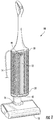
- Fig. 1 illustrates a vacuum cleaner 10.
- the vacuum cleaner 10 includes a visual display 12 located on a front side of a dirt collector 14 of the vacuum 10 that indicates to the user a fill level of the dirt collector 14. Therefore, the user can monitor the fill level of the dirt collector 14 during use of the vacuum 10 to determine when to empty or replace the dirt collector 14.
- the illustrated vacuum cleaner 10 includes a suction source 16 and a suction nozzle 18.
- the suction source 16 generates a suction airflow through the nozzle 18 to draw debris from the surface being cleaned through the nozzle 18 with the suction airflow.
- the suction source 18 includes a fan and a motor.
- the motor is a battery powered motor and in other embodiments, the motor is an alternating current motor.
- the suction source 16 is located in the suction airflow path between the nozzle 18 and the dirt collector 14. In other embodiments, the suction source 16 can be positioned downstream or after the dirt collector in the suction airflow path.
- the dirt collector 14 is in fluid communication with the suction source 16 and the nozzle 18.
- the dirt collector 14 separates the debris from the suction airflow and stores the separated debris.
- the dirt collector 14 includes a top housing or end cap 24 and an air-permeable filter media 22 extending from the housing 24 such that the filter media 22 and housing 24 at least partially define a collection volume.
- the dirt collector 14 includes a bottom housing or end cap 26 and the filter media 22 extends between the top housing or end cap 24 and bottom housing or end cap 26.
- the filter media 22 is air permeable so that the filter media 22 allows clean air to exit the filter media 22 while retaining the debris inside a storage volume 28 defined by the media 28 and the end caps 24, 26.
- the end caps 24, 26 are generally not air permeable.
- the illustrated dirt collector 14 includes a filter media 22, in other embodiments, the dirt collector can include a cyclonic separator or a combination of a cyclonic separator and a filter or filters.
- the dirt collector 14 includes a top end 30 and a bottom end 32.
- the dirt collector 14 is filled with debris starting at the bottom end 32 and as the amount of debris stored increases, the fill level rises toward the top end 30.
- the dirt collector fill level can be determined by measuring the fill level as it rises toward the top end 30.
- the dirt collector fill level can also be determined by measuring a differential pressure across the filter media 22. That is, the difference in pressure between the pressure in the storage volume 28 or in the airflow path and the atmospheric pressure outside the storage volume (or inside the storage volume 28 when the suction source 16 is not operating) can be correlated to the fill level.
- the dirt collector fill level is a function of both the differential pressure and the amount of debris in the storage volume 28.
- the vacuum cleaner 10 further includes a first sensor 34, a second sensor 36, and a controller 38 that receives signals from the sensors 34 and 36.
- the first sensor 34 in the illustrated embodiment is a pressure sensor that senses the pressure inside the storage volume 28, discussed above.
- the second sensor provides a signal indicative of a distance between the sensor and an amount of debris in the storage volume.
- the second sensor 36 in the illustrated embodiment is an infrared (IR) sensor.
- the IR sensor 36 is located at the top end 30 of the dirt collector 14 and faces down toward the bottom end 32.
- the IR sensor 36 includes an emitter of an infrared light and a detector.
- the emitter may direct the IR beam having a beam angle between about 5 and 165 degrees. In the illustrated embodiment, the beam angle is between about 15 and 60 degrees, more particularly is approximately 30 degrees.
- the IR sensor includes a detector to sense light reflected back from the debris and received by the detector, whereby the sensor provides a signal indicative of the distance to the debris.
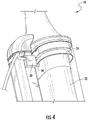
- At least a portion of the top housing 24 of the current embodiment is transmissive of electromagnetic radiation, specifically transmissive of infrared radiation, so that the IR sensor 36 is placed outside the storage volume 28 and the IR light beam travels through the transmissive housing 24 for the sensor to sense the amount of debris within the storage volume 28.
- the housing may be formed of an electromagnetic radiation transmissive material, or a window in the housing or a portion of the housing may be formed of an electromagnetic radiation transmissive material.
- the electromagnetic radiation transmissive material is selected to be transmissive of the wavelength emitted by the selected sensor and having a percent transmission selected for the sensor to provide a signal indicative of the distance to the debris.
- the housing is formed of a material that transmits infrared radiation of a wavelength between 750 and 3000 nanometer (nm), and a percent transmission of infrared radiation of greater than or equal to 50% measured at the selected sensor wavelength.
- the material may have a percent transmission of infrared radiation of greater than or equal to 65% measured at the selected sensor wavelength.
- the material may have a percent transmission of infrared radiation of greater than or equal to 80% measured at the selected sensor wavelength.
- the selected sensor is an IR sensor emitting a wavelength between 800 and 1000 nanometer (nm), and in one example is 850 nanometer (nm).
- the housing material is an IR transmissive polycarbonate having a material thickness less than 2 millimeters (mm).
- the transmissive housing material may have a thickness between 1 and 2 millimeters (mm).
- the transmissive housing material may have a thickness between 1 ⁇ 2 and 2 millimeters (mm).
- the transmissive housing material may be acrylic or other infrared transmissive materials.
- the housing 24 material includes MAKROLON 2805.
- the transmissive housing material may be transparent or translucent.
- the second sensor 36 can include a pressure sensor, an opacity sensor, an electromagnetic radiation sensor, an ultra-sonic sensor, or a camera providing a signal indicative of an amount of debris in the dirt collector.
- the controller 38 receives signals from the sensors 34, 36 and processes the signals to determine a dirt collector fill level. The controller 38 then outputs the dirt collector fill level to the visual display 12.
- the dirt collector fill level is a function of the bottom to top fill amount 40 ( Fig. 6 ) of debris in the storage volume 28 and the differential pressure across the filter media 22. In other embodiments, the dirt collector fill level may be based on only one of these variables or one of these variables in combination with another variable.
- the visual display 12 displays the dirt collector fill level determined by the controller 38.
- the visual display 12 includes a first or lower end 42 adjacent the bottom end 32 of the dirt collector 14 and a second or upper end 44 adjacent the top end 30 of the dirt collector 14.
- the visual display 12 includes an array of light emitting diodes (LEDs) that extends from the first end 42 to the second end 44 of the display 12.
- the LEDs provide an indicator that travels from the bottom end 42 to the upper end 44 as the dirt collector fill level increases to indicate to the user the fill level.
- the LED indicator lights up from the bottom end 42 to the upper end 44 generally corresponding to the increasing dirt collector fill level to indicate to the user the fill level.
- Fig. 9 illustrates one possible firmware logic diagram of the controller 38 to determine the dirt collector fill level as a function of the signals from the pressure sensor 34 and the IR sensor 36.
- the controller 38 uses the signals from the first sensor 34 (pressure sensor in illustrated embodiment) and the second sensor 36 (IR sensor in illustrated embodiment) to determine the dirt collector fill level.
- the controller 38 determines a first fill level based on the first sensor 34 signal and a second fill level based on the second sensor 36 signal.
- the controller 38 determines the higher of the first and second fill levels to be a container fill level amount. Then, the controller outputs the container fill level amount to the visual display 12.
- the controller would output a 75 percent container fill level amount to the display.
- the visual display 12 has a length 48 measured from the bottom end 42 to the top end 44. If the controller 38 determines that the dirt collector 14 is 75 percent full, then 75 percent of the length 48 of the LEDs, starting from the bottom end 42, will be lit to indicate 75 percent full dirt collector 14 to the user.
- a 75 percent fill level may or may not equal 75% of the bottom to top volumetric fill amount 40 of the storage volume 28 because the percent fill level is also a function of the pressure sensed by the sensor 34.
- the user may use the vacuum 10 to collect very fine debris that has a relatively low volume but attaches to the filter media 22 and increases the differential pressure across the filter media more rapidly than coarse or large debris. Therefore, the visual display could display 100 percent fill level when the bottom to top fill amount 40 is still relatively low.
- the fill level display 12 may include a scale from 0%-100% (or similar) that is a graphical representation of the fill level and not the actual distance 40 ( Fig. 6 ).
- the controller 38 uses an average of outputs from the first and second sensors 34, 36 to determine the fill level. For example, the controller determines the first fill level based on the first sensor signal and the second fill level based on the second sensor signal, and then determines an average of the first and second fill levels to be the displayed fill level amount. In other embodiments, the controller uses a formula or look-up table to combine the first and second sensor outputs based on empirical or other information including sensor reliability, sensor accuracy, and system attributes of the first and second sensors and the vacuum cleaner. For one example, the fill level determined by a pressure reading may be adjusted by a function of the distance between the sensor and an amount of debris in the storage volume measured by the second sensor.
- the IR sensor accuracy may diminish as the dirt container fills, and the controller may adjust the IR distance measurement as a function of the pressure differential measured by the first sensor.
- Other system and performance attributes may be taken into account in determining the container fill level.
- the controller determines the displayed fill level amount based on one of the two sensors alone until the other of the sensors reaches a threshold, after which time the displayed fill level is determined by a function of both the first sensor signal and the second sensor signal as described.
- the displayed fill level may be based on the IR sensor signal alone until the differential pressure measured by the pressure sensor reaches a predetermined threshold, after which time the displayed fill level is determined by a function of both the pressure and IR sensor signals.
Landscapes
- Engineering & Computer Science (AREA)
- Mechanical Engineering (AREA)
- Physics & Mathematics (AREA)
- Chemical & Material Sciences (AREA)
- Chemical Kinetics & Catalysis (AREA)
- Electromagnetism (AREA)
- Thermal Sciences (AREA)
- Fluid Mechanics (AREA)
- General Physics & Mathematics (AREA)
- Electric Vacuum Cleaner (AREA)
- Filters For Electric Vacuum Cleaners (AREA)
Claims (7)
- Staubsauger (10), umfassend:eine Saugquelle (16), die dafür konfiguriert ist, einen Saugluftstrom zu erzeugen;einen Schmutzsammler (14), der in Fluidkommunikation mit der Saugquelle steht und dafür konfiguriert ist, Schmutz aus dem Saugluftstrom abzuscheiden, und wobei der Schmutzsammler (14) dafür konfiguriert ist, aus dem Saugluftstrom abgeschiedenen Schmutz zu speichern;einen Infrarotsensor (36), der betreibbar ist zum Ausgeben eines Signals, das einem Abstand zu einer in dem Schmutzsammler (14) gespeicherten Schmutzmenge entspricht;ein Steuergerät (38), das das Signal entgegennimmt, wobei das Steuergerät (38) betreibbar ist zum Bestimmen eines Füllstands in dem Schmutzsammler (14) auf Basis des Signals; undeine Sichtanzeige (12), die den Füllstand in dem Schmutzsammler (14) anzeigt.
- Staubsauger (10) nach Anspruch 1, wobei der Schmutzsammler (14) ein oberes Ende (30) und ein unteres Ende (32) beinhaltet, wobei sich der Infrarotsensor (36) neben dem oberen Ende (30) befindet und dem unteren Ende (32) zugewandt ist, um die in dem Schmutzsammler (14) gespeicherte Schmutzmenge zu bestimmen.
- Staubsauger (10) nach Anspruch 2, wobei die Sichtanzeige (12) ein erstes Ende (42) und ein zweites Ende (44) beinhaltet und die Sichtanzeige (12) einen Indikator beinhaltet, der sich von dem ersten Ende (42) hin zu dem zweiten Ende (44) bewegt, während der Schmutzsammler-Füllstand zunimmt.
- Staubsauger (10) nach Anspruch 3, wobei der Indikator eine Anordnung von Leuchtdioden beinhaltet.
- Staubsauger (10) nach Anspruch 1, ferner umfassend einen Luftdrucksensor (34), der betreibbar ist zum Ausgeben eines einem Druck innerhalb des Schmutzsammlers (14) entsprechenden Signals.
- Staubsauger (10) nach Anspruch 5, wobei das Steuergerät (38) betreibbar ist zum Bestimmen eines ersten Füllstands auf Basis des Luftdrucksensorsignals und eines zweiten Füllstands auf Basis des Infrarotsensorsignals, wobei der Füllstand des Schmutzsammlers der höhere des ersten und zweiten Füllstands ist.
- Staubsauger (10) nach Anspruch 5, wobei das Steuergerät (38) betreibbar ist zum Bestimmen des Füllstands mithilfe mindestens einer/eines der folgenden: einer Kombination der Ausgänge aus den Luftdruck- und Infrarotsensoren (34, 36), eines Durchschnitts der Ausgänge aus den Luftdruck- und Infrarotsensoren (34, 36); einer Formel oder Nachschlagetabelle zum Kombinieren der Luftdruck- und Infrarotsensorausgänge auf Basis von empirischen oder anderen Informationen einschließlich Sensorzuverlässigkeit, Sensorgenauigkeit und Systemattributen.
Priority Applications (1)
| Application Number | Priority Date | Filing Date | Title |
|---|---|---|---|
| EP21176706.6A EP3895592A1 (de) | 2017-09-28 | 2018-09-26 | Schmutzfänger für einen staubsauger |
Applications Claiming Priority (4)
| Application Number | Priority Date | Filing Date | Title |
|---|---|---|---|
| US201762564432P | 2017-09-28 | 2017-09-28 | |
| US201762572229P | 2017-10-13 | 2017-10-13 | |
| US201762572225P | 2017-10-13 | 2017-10-13 | |
| PCT/US2018/052811 WO2019067512A2 (en) | 2017-09-28 | 2018-09-26 | VACUUM CLEANER AND COLLECTOR FOR VACUUM CLEANER |
Related Child Applications (2)
| Application Number | Title | Priority Date | Filing Date |
|---|---|---|---|
| EP21176706.6A Division-Into EP3895592A1 (de) | 2017-09-28 | 2018-09-26 | Schmutzfänger für einen staubsauger |
| EP21176706.6A Division EP3895592A1 (de) | 2017-09-28 | 2018-09-26 | Schmutzfänger für einen staubsauger |
Publications (2)
| Publication Number | Publication Date |
|---|---|
| EP3687359A2 EP3687359A2 (de) | 2020-08-05 |
| EP3687359B1 true EP3687359B1 (de) | 2021-07-07 |
Family
ID=63858141
Family Applications (2)
| Application Number | Title | Priority Date | Filing Date |
|---|---|---|---|
| EP18786565.4A Active EP3687359B1 (de) | 2017-09-28 | 2018-09-26 | Staubsauger |
| EP21176706.6A Withdrawn EP3895592A1 (de) | 2017-09-28 | 2018-09-26 | Schmutzfänger für einen staubsauger |
Family Applications After (1)
| Application Number | Title | Priority Date | Filing Date |
|---|---|---|---|
| EP21176706.6A Withdrawn EP3895592A1 (de) | 2017-09-28 | 2018-09-26 | Schmutzfänger für einen staubsauger |
Country Status (4)
| Country | Link |
|---|---|
| US (5) | US11083354B2 (de) |
| EP (2) | EP3687359B1 (de) |
| CN (1) | CN111132591B (de) |
| WO (1) | WO2019067512A2 (de) |
Families Citing this family (25)
| Publication number | Priority date | Publication date | Assignee | Title |
|---|---|---|---|---|
| WO2017181048A1 (en) * | 2016-04-15 | 2017-10-19 | Tti (Macao Commercial Offshore) Limited | Vacuum filter |
| US11219906B2 (en) * | 2019-01-23 | 2022-01-11 | Omachron Intellectual Property Inc. | Surface cleaning apparatus, cyclonic air treatment member and surface cleaning apparatus including the same |
| US10966583B2 (en) * | 2019-01-23 | 2021-04-06 | Omachron Intellectual Property Inc. | Surface cleaning apparatus, cyclonic air treatment member and surface cleaning apparatus including the same |
| US11858155B1 (en) * | 2018-07-30 | 2024-01-02 | AI Incorporated | Electronic razor with suction |
| US10974258B2 (en) * | 2019-01-23 | 2021-04-13 | Omachron Intellectual Property Inc. | Surface cleaning apparatus, cyclonic air treatment member and surface cleaning apparatus including the same |
| US10919051B2 (en) * | 2019-01-23 | 2021-02-16 | Omachron Intellectual Property Inc. | Surface cleaning apparatus, cyclonic air treatment member and surface cleaning apparatus including the same |
| US10925451B2 (en) * | 2019-01-23 | 2021-02-23 | Omachron Intellectual Property Inc. | Surface cleaning apparatus, cyclonic air treatment member and surface cleaning apparatus including the same |
| US11129510B2 (en) * | 2019-01-23 | 2021-09-28 | Omachron Intellectual Property Inc. | Surface cleaning apparatus, cyclonic air treatment member and surface cleaning apparatus including the same |
| US11213832B2 (en) * | 2019-01-23 | 2022-01-04 | Omachron Intellectual Property Inc. | Surface cleaning apparatus, cyclonic air treatment member and surface cleaning apparatus including the same |
| US11135602B2 (en) * | 2019-01-23 | 2021-10-05 | Omachron Intellectual Property Inc. | Surface cleaning apparatus, cyclonic air treatment member and surface cleaning apparatus including the same |
| GB2596442B (en) | 2019-03-15 | 2022-12-14 | Omachron Intellectual Property Inc | Surface cleaning apparatus |
| CN111839345A (zh) * | 2019-04-24 | 2020-10-30 | 苏州市春菊电器有限公司 | 一种吸尘器的吸力自动调节方法及系统 |
| DE102020116166A1 (de) * | 2020-06-18 | 2021-06-24 | Aebi Schmidt Deutschland Gmbh | Selbstfahrende Kehrmaschine |
| US11122946B2 (en) | 2021-03-04 | 2021-09-21 | Bissell Inc. | Brushroll for surface cleaning apparatus |
| CA3152680C (en) | 2021-03-17 | 2025-02-11 | Dupray Ventures Inc. | STAIN REMOVAL DEVICE |
| WO2022212120A1 (en) | 2021-04-01 | 2022-10-06 | Bissell Inc. | Surface cleaning apparatus with lighting |
| BE1029737B1 (de) | 2021-09-08 | 2023-04-03 | Miele & Cie | Staubsauger, Staubbeutel, System und Verfahren |
| CN114468889B (zh) * | 2021-12-24 | 2023-06-23 | 添可智能科技有限公司 | 回收桶状态检测方法、处理系统及清洁设备 |
| CN114916880B (zh) * | 2022-04-25 | 2023-06-23 | 添可智能科技有限公司 | 容器、液位检测方法、清洁设备及存储介质 |
| USD1017156S1 (en) | 2022-05-09 | 2024-03-05 | Dupray Ventures Inc. | Cleaner |
| JP1779640S (ja) * | 2023-04-19 | 2024-09-10 | 手持ち式掃除機 | |
| USD1086623S1 (en) * | 2023-09-19 | 2025-07-29 | Bissell Inc. | Floor cleaner |
| USD1091031S1 (en) * | 2024-02-20 | 2025-08-26 | Yunjing Intelligence Innovation (Shenzhen) Co., Ltd. | Cleaning device |
| USD1107357S1 (en) * | 2024-05-14 | 2025-12-23 | Guangdong Deerma Health Technology Co., Ltd. | Vacuum cleaner |
| US12471748B1 (en) * | 2024-05-15 | 2025-11-18 | Nilfisk A/S | Debris basket indicator system |
Family Cites Families (85)
| Publication number | Priority date | Publication date | Assignee | Title |
|---|---|---|---|---|
| US3631654A (en) | 1968-10-03 | 1972-01-04 | Pall Corp | Gas purge device |
| US3891417A (en) | 1974-01-28 | 1975-06-24 | King Eng Corp | Filter and sorbent cartridge |
| GB2109268B (en) | 1981-11-16 | 1984-10-03 | Process Scient Innovations | Gas purifiers |
| GB2214837B (en) | 1988-02-17 | 1991-09-04 | Process Scient Innovations | Oil coalescing filter |
| DE4014442A1 (de) * | 1990-05-05 | 1991-11-07 | Duepro Ag | Vorrichtung zur anzeige des verschmutzungsgrades von luftfiltern in saugreinigungsgeraeten, raumfiltern o. dgl. |
| US5311023A (en) * | 1992-10-13 | 1994-05-10 | Means Jr Orville D | Filter inspection apparatus |
| DE4413081C1 (de) * | 1994-04-15 | 1995-03-09 | Sartorius Gmbh | Verfahren und Vorrichtung zur Integritätsprüfung von Filterelementen in Räumen mit besonderen Sicherheitsanforderungen |
| US6029309A (en) | 1997-04-08 | 2000-02-29 | Yashima Electric Co., Ltd. | Vacuum cleaner with dust bag fill detector |
| WO1999034722A1 (en) * | 1998-01-09 | 1999-07-15 | Royal Appliance Mfg. Co. | Upright vacuum cleaner with cyclonic airflow |
| US6058560A (en) | 1998-08-04 | 2000-05-09 | Gab; Wayne Gerard | Vac-in-a-box |
| DE69831164D1 (de) | 1998-09-30 | 2005-09-15 | St Microelectronics Srl | Verfahren und Vorrichtung zur Bestimmung und Anzeige des Füllungsgrads von Staubbeuteln bei Staubsaugern |
| JP3530436B2 (ja) * | 1999-01-29 | 2004-05-24 | 三洋電機株式会社 | 掃除機用集塵装置及びアップライト型掃除機 |
| JP2001221746A (ja) * | 2000-02-03 | 2001-08-17 | Suntory Ltd | 液体充填用容器の撮像方法および装置 |
| US6571422B1 (en) | 2000-08-01 | 2003-06-03 | The Hoover Company | Vacuum cleaner with a microprocessor-based dirt detection circuit |
| WO2002038025A1 (en) * | 2000-11-13 | 2002-05-16 | Matsushita Electric Corporation Of America | Cyclonic vacuum cleaner with filter and filter sweeper |
| US6447586B1 (en) * | 2000-12-06 | 2002-09-10 | Whirlpool Corporation | Air treatment appliance with a translucent body |
| US7012685B1 (en) | 2001-08-06 | 2006-03-14 | Wilson David J | Clogged filter detector |
| DE10208366A1 (de) | 2002-02-27 | 2003-09-04 | Bsh Bosch Siemens Hausgeraete | Staubsauger mit Lichtleiterelement |
| JP2003339583A (ja) * | 2002-05-30 | 2003-12-02 | Matsushita Electric Ind Co Ltd | 電気掃除機 |
| US7811346B1 (en) * | 2002-06-28 | 2010-10-12 | Joseph Clarence Henson | Filter housing |
| US6979361B2 (en) | 2002-07-17 | 2005-12-27 | Gueorgui Milev Mihayiov | End of service life indicator for fluid filter |
| US7424766B2 (en) | 2003-09-19 | 2008-09-16 | Royal Appliance Mfg. Co. | Sensors and associated methods for controlling a vacuum cleaner |
| US7599758B2 (en) | 2003-09-19 | 2009-10-06 | Royal Appliance Mfg. Co. | Sensors and associated methods for controlling a vacuum cleaner |
| US7237298B2 (en) | 2003-09-19 | 2007-07-03 | Royal Appliance Mfg. Co. | Sensors and associated methods for controlling a vacuum cleaner |
| US20050183230A1 (en) | 2004-01-30 | 2005-08-25 | Funai Electric Co., Ltd. | Self-propelling cleaner |
| JP2008510135A (ja) * | 2004-08-11 | 2008-04-03 | コーニンクレッカ フィリップス エレクトロニクス エヌ ヴィ | 空気汚染センサシステム |
| US20060075899A1 (en) | 2004-10-04 | 2006-04-13 | O'brien & Gere Engineers, Inc. | Disposable HEPA filtration adapter |
| US7461430B2 (en) | 2005-01-10 | 2008-12-09 | Broan-Nutone Llc | Vacuum system and method |
| CA2602700C (en) | 2005-03-03 | 2013-06-25 | Nilfisk-Advance A/S | A method of determining the degree of filling of the dust collector of a vacuum cleaner and a filling indicator |
| DE102005045544A1 (de) | 2005-09-23 | 2007-03-29 | Vorwerk & Co. Interholding Gmbh | Verfahren zum Generieren eines Signals zum Filterbeutelwechsel sowie Staubsauger mit einem Sauggebläse |
| US7673368B2 (en) * | 2005-10-18 | 2010-03-09 | Panasonic Corporation Of North America | Dust bag arrangement and filling indicator for floor care apparatus |
| DE102005050635B4 (de) | 2005-10-20 | 2016-06-09 | Knorr-Bremse Systeme für Nutzfahrzeuge GmbH | System und Verfahren zum Erkennen von Eigenschaften einer Luftfilterpatrone |
| US7785396B2 (en) | 2005-12-10 | 2010-08-31 | Lg Electronics Inc. | Vacuum cleaner with removable dust collector, and methods of operating the same |
| US8012250B2 (en) | 2005-12-10 | 2011-09-06 | Lg Electronics Inc. | Vacuum cleaner |
| US7749295B2 (en) | 2005-12-10 | 2010-07-06 | Lg Electronics Inc. | Vacuum cleaner with removable dust collector, and methods of operating the same |
| US8404034B2 (en) | 2005-12-10 | 2013-03-26 | Lg Electronics Inc. | Vacuum cleaner and method of controlling the same |
| US7770253B2 (en) | 2005-12-10 | 2010-08-10 | Lg Electronics Inc. | Vacuum cleaner with removable dust collector, and methods of operating the same |
| US7823249B2 (en) | 2006-01-05 | 2010-11-02 | The Scott Fetzer Company | Motor control for a vacuum cleaner |
| NL1031010C2 (nl) | 2006-01-26 | 2007-07-27 | Bravilor Holding Bv | Vultoestanddetectie-inrichting voor poedervormig materiaal en werkwijze voor het detecteren van een vultoestand in een opslageenheid. |
| US7509707B2 (en) | 2006-02-06 | 2009-03-31 | Panasonic Corporation Of North America | Floor cleaning apparatus with dirt detection sensor |
| JP4342526B2 (ja) | 2006-03-14 | 2009-10-14 | 株式会社東芝 | 電気掃除機 |
| EP1836941B1 (de) | 2006-03-14 | 2014-02-12 | Toshiba TEC Kabushiki Kaisha | Elektrischer Staubsauger |
| CN101547729B (zh) | 2006-10-08 | 2014-01-22 | 斯特劳斯水业有限公司 | 流体过滤器监测设备 |
| EP1949842B1 (de) | 2007-01-24 | 2015-03-04 | LG Electronics Inc. | Staubsauger |
| CN201098592Y (zh) | 2007-09-25 | 2008-08-13 | 潘志伟 | 自报警空气净化器 |
| US7751990B2 (en) | 2008-07-21 | 2010-07-06 | International Business Machines Corporation | Detecting a fouled air filter in a computer equipment enclosure |
| US8028942B2 (en) | 2008-08-01 | 2011-10-04 | Fellowes, Inc. | Bin full detection with light intensity sensing |
| US8424153B2 (en) * | 2009-03-19 | 2013-04-23 | Bissell Homecare, Inc. | Vacuum cleaner and filters therefor |
| TWI399190B (zh) | 2009-05-21 | 2013-06-21 | Ind Tech Res Inst | 清潔裝置、及其偵測方法 |
| KR101103910B1 (ko) | 2009-07-24 | 2012-01-12 | 주식회사 모뉴엘 | 로봇청소기용 먼지감지센서 구조 |
| EP2386238B1 (de) | 2010-03-23 | 2019-03-06 | Stein & Co. GmbH | Staubsauger mit einem leistungsgeregelten Saugmotor |
| EP2553436B1 (de) | 2010-04-02 | 2020-03-04 | 3M Innovative Properties Company | Filtersysteme mit optischen analytsensoren und optischen lesegeräten |
| CN102803936B (zh) | 2010-04-02 | 2016-03-23 | 3M创新有限公司 | 包括图案化光学被分析物传感器和光学读出器的过滤器系统 |
| DE102010016791B4 (de) | 2010-05-05 | 2012-03-15 | Miele & Cie. Kg | Staubsauger mit einem Filter |
| SE534962C2 (sv) | 2010-06-29 | 2012-02-28 | Electrolux Ab | Dammdetekteringssystem för en dammsugare |
| DE102010034176A1 (de) | 2010-08-12 | 2012-02-16 | Würth Elektronik Ics Gmbh & Co. Kg | Behälter mit Erfassungsvorrichtung |
| US9104211B2 (en) * | 2010-11-19 | 2015-08-11 | Google Inc. | Temperature controller with model-based time to target calculation and display |
| EP2618909A4 (de) | 2010-09-20 | 2014-06-18 | Surgiquest Inc | Filterungssystem mit mehreren strömungen |
| US20120152280A1 (en) | 2010-12-18 | 2012-06-21 | Zenith Technologies, Llc | Touch Sensitive Display For Surface Cleaner |
| WO2012088426A2 (en) | 2010-12-23 | 2012-06-28 | Caterpillar Inc. | Method and apparatus for measuring ash deposit levels in a particulate filter |
| WO2012092565A1 (en) | 2010-12-30 | 2012-07-05 | Irobot Corporation | Debris monitoring |
| US8726457B2 (en) | 2011-12-30 | 2014-05-20 | Techtronic Floor Care Technology Limited | Vacuum cleaner with display |
| US9038236B2 (en) | 2012-04-25 | 2015-05-26 | Shop Vac Corporation | Filter shaker |
| US8744780B2 (en) * | 2012-04-27 | 2014-06-03 | Filtersmarts, Inc. | Detector for clogged filters |
| DE102012110758A1 (de) | 2012-11-09 | 2014-05-15 | Vorwerk & Co. Interholding Gmbh | Luftfilteranordnung sowie Verfahren zur Messung eines Belastungsgrades einer solchen Luftfilteranordnung |
| WO2015094049A1 (en) | 2013-12-19 | 2015-06-25 | Camfil Ab | Air filtering device with means for salt load determination and method for monitoring filtration |
| US9821260B2 (en) * | 2014-02-14 | 2017-11-21 | Access Business Group International Llc | Air treatment system |
| CN104856612A (zh) | 2014-02-20 | 2015-08-26 | 深圳市恒润晖光电科技有限公司 | 自走吸尘器及其垃圾检测装置 |
| CN204056884U (zh) | 2014-03-11 | 2014-12-31 | 陈世席 | 智能垃圾桶 |
| WO2015199669A1 (en) | 2014-06-25 | 2015-12-30 | Halliburton Energy Services, Inc. | In situ evaluation of filter parameters with opticoanalytical devices |
| EP3018423B1 (de) | 2014-11-04 | 2019-08-07 | Samsung Electronics Co., Ltd. | Verunreinigungssensor, luftreiniger damit und steuerungsverfahren dafür |
| US10357733B2 (en) | 2014-11-13 | 2019-07-23 | Cts Corporation | Filter retentate removal system and method |
| WO2016100878A1 (en) * | 2014-12-19 | 2016-06-23 | Techtronic Industries Co. Ltd. | Autonomous vacuum |
| US9846077B2 (en) | 2015-01-26 | 2017-12-19 | H2Optx Inc. | Devices and methods for analyzing granular samples |
| DE102015003916A1 (de) * | 2015-03-27 | 2016-09-29 | Nilfisk-Advance A/S | Schmutzsammelvorrichtung für ein Reinigungsgerät, insbesondere ein Kehrfahrzeug sowie Staubsaugerdüse für einen Staubsauger und Verfahren zum Betrieb beider Vorrichtungen |
| CN104857780A (zh) | 2015-06-13 | 2015-08-26 | 黄浩 | 一种多体式袋式除尘器 |
| WO2017004313A1 (en) | 2015-06-30 | 2017-01-05 | 3M Innovative Properties Company | Filter cartridge comprising filter media with adhesively edge-sealed ends, and method of making and using |
| US20170000305A1 (en) | 2015-06-30 | 2017-01-05 | Techtronic Industries Co. Ltd. | Vacuum cleaner with brushroll control |
| US9908072B2 (en) | 2015-10-06 | 2018-03-06 | Lennox Industries Inc. | System and method for replacing air filters |
| US10568477B2 (en) * | 2016-04-11 | 2020-02-25 | Omachron Intellectual Property Inc. | Surface cleaning apparatus |
| CN106115119A (zh) | 2016-06-30 | 2016-11-16 | 深圳市智汇十方科技有限公司 | 一种小区垃圾处理方法 |
| US10913661B2 (en) * | 2016-08-22 | 2021-02-09 | Tender Corporation | Multi-stage filter assembly |
| US10213082B2 (en) | 2016-08-30 | 2019-02-26 | Samsung Electronics Co., Ltd. | Robot cleaner |
| CN206318279U (zh) | 2016-10-17 | 2017-07-11 | 三峡大学 | 一种可分类的垃圾收集装置 |
| US10958991B2 (en) | 2017-09-15 | 2021-03-23 | Mann+Hummel Gmbh | Filter element sensor module having processing and wireless communication capabilities |
-
2018
- 2018-09-26 EP EP18786565.4A patent/EP3687359B1/de active Active
- 2018-09-26 EP EP21176706.6A patent/EP3895592A1/de not_active Withdrawn
- 2018-09-26 US US16/142,201 patent/US11083354B2/en not_active Expired - Fee Related
- 2018-09-26 CN CN201880063303.4A patent/CN111132591B/zh active Active
- 2018-09-26 WO PCT/US2018/052811 patent/WO2019067512A2/en not_active Ceased
- 2018-09-26 US US16/142,177 patent/US11058273B2/en active Active
-
2021
- 2021-07-12 US US17/373,528 patent/US11612292B2/en active Active
- 2021-07-12 US US17/373,500 patent/US11612291B2/en active Active
- 2021-08-03 US US17/392,794 patent/US20210361135A1/en not_active Abandoned
Also Published As
| Publication number | Publication date |
|---|---|
| WO2019067512A2 (en) | 2019-04-04 |
| CN111132591A (zh) | 2020-05-08 |
| US20210361135A1 (en) | 2021-11-25 |
| US11612291B2 (en) | 2023-03-28 |
| US20190125152A1 (en) | 2019-05-02 |
| US11083354B2 (en) | 2021-08-10 |
| US11058273B2 (en) | 2021-07-13 |
| US20190090710A1 (en) | 2019-03-28 |
| CN111132591B (zh) | 2022-08-02 |
| US20210338027A1 (en) | 2021-11-04 |
| US20210338026A1 (en) | 2021-11-04 |
| EP3687359A2 (de) | 2020-08-05 |
| US11612292B2 (en) | 2023-03-28 |
| EP3895592A1 (de) | 2021-10-20 |
| WO2019067512A3 (en) | 2019-05-23 |
Similar Documents
| Publication | Publication Date | Title |
|---|---|---|
| US11612292B2 (en) | Vacuum cleaner | |
| CN207575101U (zh) | 机器人吸尘器 | |
| US7921506B2 (en) | Robot cleaner having function for detecting separation of dust tank and control method thereof | |
| KR101046838B1 (ko) | 진공 청소기 | |
| EP2587979B1 (de) | Stauberkennungseinrichtung | |
| KR20230113231A (ko) | 로봇 청소기 | |
| US20150068182A1 (en) | Material collection system sensor | |
| KR20180045356A (ko) | 청소기 및 그 제어방법 | |
| JP5620127B2 (ja) | 電気掃除機 | |
| US20150197096A1 (en) | Cartridge Type Ink Jet Recording Apparatus | |
| JPWO2012133571A1 (ja) | 電気掃除機 | |
| JP5006091B2 (ja) | 電気掃除機 | |
| KR20120106404A (ko) | 진공청소기의 먼지 검출장치 및 먼지 검출방법 | |
| JP2012200462A (ja) | 電気掃除機 | |
| KR20190020006A (ko) | 청소기 및 그 제어방법 | |
| KR101841448B1 (ko) | 진공 청소기 | |
| EP4201289A2 (de) | Reinigungsroboter |
Legal Events
| Date | Code | Title | Description |
|---|---|---|---|
| STAA | Information on the status of an ep patent application or granted ep patent |
Free format text: STATUS: UNKNOWN |
|
| STAA | Information on the status of an ep patent application or granted ep patent |
Free format text: STATUS: THE INTERNATIONAL PUBLICATION HAS BEEN MADE |
|
| PUAI | Public reference made under article 153(3) epc to a published international application that has entered the european phase |
Free format text: ORIGINAL CODE: 0009012 |
|
| STAA | Information on the status of an ep patent application or granted ep patent |
Free format text: STATUS: REQUEST FOR EXAMINATION WAS MADE |
|
| 17P | Request for examination filed |
Effective date: 20200325 |
|
| AK | Designated contracting states |
Kind code of ref document: A2 Designated state(s): AL AT BE BG CH CY CZ DE DK EE ES FI FR GB GR HR HU IE IS IT LI LT LU LV MC MK MT NL NO PL PT RO RS SE SI SK SM TR |
|
| AX | Request for extension of the european patent |
Extension state: BA ME |
|
| RAP1 | Party data changed (applicant data changed or rights of an application transferred) |
Owner name: TTI (MACAO COMMERCIAL OFFSHORE) LIMITED |
|
| DAV | Request for validation of the european patent (deleted) | ||
| DAX | Request for extension of the european patent (deleted) | ||
| GRAP | Despatch of communication of intention to grant a patent |
Free format text: ORIGINAL CODE: EPIDOSNIGR1 |
|
| STAA | Information on the status of an ep patent application or granted ep patent |
Free format text: STATUS: GRANT OF PATENT IS INTENDED |
|
| INTG | Intention to grant announced |
Effective date: 20210201 |
|
| GRAS | Grant fee paid |
Free format text: ORIGINAL CODE: EPIDOSNIGR3 |
|
| GRAA | (expected) grant |
Free format text: ORIGINAL CODE: 0009210 |
|
| STAA | Information on the status of an ep patent application or granted ep patent |
Free format text: STATUS: THE PATENT HAS BEEN GRANTED |
|
| AK | Designated contracting states |
Kind code of ref document: B1 Designated state(s): AL AT BE BG CH CY CZ DE DK EE ES FI FR GB GR HR HU IE IS IT LI LT LU LV MC MK MT NL NO PL PT RO RS SE SI SK SM TR |
|
| REG | Reference to a national code |
Ref country code: GB Ref legal event code: FG4D |
|
| REG | Reference to a national code |
Ref country code: AT Ref legal event code: REF Ref document number: 1407735 Country of ref document: AT Kind code of ref document: T Effective date: 20210715 |
|
| REG | Reference to a national code |
Ref country code: DE Ref legal event code: R096 Ref document number: 602018019846 Country of ref document: DE |
|
| REG | Reference to a national code |
Ref country code: IE Ref legal event code: FG4D |
|
| REG | Reference to a national code |
Ref country code: LT Ref legal event code: MG9D |
|
| REG | Reference to a national code |
Ref country code: NL Ref legal event code: MP Effective date: 20210707 |
|
| REG | Reference to a national code |
Ref country code: AT Ref legal event code: MK05 Ref document number: 1407735 Country of ref document: AT Kind code of ref document: T Effective date: 20210707 |
|
| PG25 | Lapsed in a contracting state [announced via postgrant information from national office to epo] |
Ref country code: RS Free format text: LAPSE BECAUSE OF FAILURE TO SUBMIT A TRANSLATION OF THE DESCRIPTION OR TO PAY THE FEE WITHIN THE PRESCRIBED TIME-LIMIT Effective date: 20210707 Ref country code: SE Free format text: LAPSE BECAUSE OF FAILURE TO SUBMIT A TRANSLATION OF THE DESCRIPTION OR TO PAY THE FEE WITHIN THE PRESCRIBED TIME-LIMIT Effective date: 20210707 Ref country code: FI Free format text: LAPSE BECAUSE OF FAILURE TO SUBMIT A TRANSLATION OF THE DESCRIPTION OR TO PAY THE FEE WITHIN THE PRESCRIBED TIME-LIMIT Effective date: 20210707 Ref country code: ES Free format text: LAPSE BECAUSE OF FAILURE TO SUBMIT A TRANSLATION OF THE DESCRIPTION OR TO PAY THE FEE WITHIN THE PRESCRIBED TIME-LIMIT Effective date: 20210707 Ref country code: HR Free format text: LAPSE BECAUSE OF FAILURE TO SUBMIT A TRANSLATION OF THE DESCRIPTION OR TO PAY THE FEE WITHIN THE PRESCRIBED TIME-LIMIT Effective date: 20210707 Ref country code: BG Free format text: LAPSE BECAUSE OF FAILURE TO SUBMIT A TRANSLATION OF THE DESCRIPTION OR TO PAY THE FEE WITHIN THE PRESCRIBED TIME-LIMIT Effective date: 20211007 Ref country code: AT Free format text: LAPSE BECAUSE OF FAILURE TO SUBMIT A TRANSLATION OF THE DESCRIPTION OR TO PAY THE FEE WITHIN THE PRESCRIBED TIME-LIMIT Effective date: 20210707 Ref country code: LT Free format text: LAPSE BECAUSE OF FAILURE TO SUBMIT A TRANSLATION OF THE DESCRIPTION OR TO PAY THE FEE WITHIN THE PRESCRIBED TIME-LIMIT Effective date: 20210707 Ref country code: NL Free format text: LAPSE BECAUSE OF FAILURE TO SUBMIT A TRANSLATION OF THE DESCRIPTION OR TO PAY THE FEE WITHIN THE PRESCRIBED TIME-LIMIT Effective date: 20210707 Ref country code: PT Free format text: LAPSE BECAUSE OF FAILURE TO SUBMIT A TRANSLATION OF THE DESCRIPTION OR TO PAY THE FEE WITHIN THE PRESCRIBED TIME-LIMIT Effective date: 20211108 Ref country code: NO Free format text: LAPSE BECAUSE OF FAILURE TO SUBMIT A TRANSLATION OF THE DESCRIPTION OR TO PAY THE FEE WITHIN THE PRESCRIBED TIME-LIMIT Effective date: 20211007 |
|
| PG25 | Lapsed in a contracting state [announced via postgrant information from national office to epo] |
Ref country code: PL Free format text: LAPSE BECAUSE OF FAILURE TO SUBMIT A TRANSLATION OF THE DESCRIPTION OR TO PAY THE FEE WITHIN THE PRESCRIBED TIME-LIMIT Effective date: 20210707 Ref country code: LV Free format text: LAPSE BECAUSE OF FAILURE TO SUBMIT A TRANSLATION OF THE DESCRIPTION OR TO PAY THE FEE WITHIN THE PRESCRIBED TIME-LIMIT Effective date: 20210707 Ref country code: GR Free format text: LAPSE BECAUSE OF FAILURE TO SUBMIT A TRANSLATION OF THE DESCRIPTION OR TO PAY THE FEE WITHIN THE PRESCRIBED TIME-LIMIT Effective date: 20211008 |
|
| REG | Reference to a national code |
Ref country code: DE Ref legal event code: R097 Ref document number: 602018019846 Country of ref document: DE |
|
| PG25 | Lapsed in a contracting state [announced via postgrant information from national office to epo] |
Ref country code: DK Free format text: LAPSE BECAUSE OF FAILURE TO SUBMIT A TRANSLATION OF THE DESCRIPTION OR TO PAY THE FEE WITHIN THE PRESCRIBED TIME-LIMIT Effective date: 20210707 |
|
| REG | Reference to a national code |
Ref country code: CH Ref legal event code: PL |
|
| PLBE | No opposition filed within time limit |
Free format text: ORIGINAL CODE: 0009261 |
|
| STAA | Information on the status of an ep patent application or granted ep patent |
Free format text: STATUS: NO OPPOSITION FILED WITHIN TIME LIMIT |
|
| REG | Reference to a national code |
Ref country code: BE Ref legal event code: MM Effective date: 20210930 |
|
| PG25 | Lapsed in a contracting state [announced via postgrant information from national office to epo] |
Ref country code: SM Free format text: LAPSE BECAUSE OF FAILURE TO SUBMIT A TRANSLATION OF THE DESCRIPTION OR TO PAY THE FEE WITHIN THE PRESCRIBED TIME-LIMIT Effective date: 20210707 Ref country code: SK Free format text: LAPSE BECAUSE OF FAILURE TO SUBMIT A TRANSLATION OF THE DESCRIPTION OR TO PAY THE FEE WITHIN THE PRESCRIBED TIME-LIMIT Effective date: 20210707 Ref country code: RO Free format text: LAPSE BECAUSE OF FAILURE TO SUBMIT A TRANSLATION OF THE DESCRIPTION OR TO PAY THE FEE WITHIN THE PRESCRIBED TIME-LIMIT Effective date: 20210707 Ref country code: MC Free format text: LAPSE BECAUSE OF FAILURE TO SUBMIT A TRANSLATION OF THE DESCRIPTION OR TO PAY THE FEE WITHIN THE PRESCRIBED TIME-LIMIT Effective date: 20210707 Ref country code: EE Free format text: LAPSE BECAUSE OF FAILURE TO SUBMIT A TRANSLATION OF THE DESCRIPTION OR TO PAY THE FEE WITHIN THE PRESCRIBED TIME-LIMIT Effective date: 20210707 Ref country code: CZ Free format text: LAPSE BECAUSE OF FAILURE TO SUBMIT A TRANSLATION OF THE DESCRIPTION OR TO PAY THE FEE WITHIN THE PRESCRIBED TIME-LIMIT Effective date: 20210707 Ref country code: AL Free format text: LAPSE BECAUSE OF FAILURE TO SUBMIT A TRANSLATION OF THE DESCRIPTION OR TO PAY THE FEE WITHIN THE PRESCRIBED TIME-LIMIT Effective date: 20210707 |
|
| 26N | No opposition filed |
Effective date: 20220408 |
|
| PG25 | Lapsed in a contracting state [announced via postgrant information from national office to epo] |
Ref country code: LU Free format text: LAPSE BECAUSE OF NON-PAYMENT OF DUE FEES Effective date: 20210926 Ref country code: IT Free format text: LAPSE BECAUSE OF FAILURE TO SUBMIT A TRANSLATION OF THE DESCRIPTION OR TO PAY THE FEE WITHIN THE PRESCRIBED TIME-LIMIT Effective date: 20210707 Ref country code: IE Free format text: LAPSE BECAUSE OF NON-PAYMENT OF DUE FEES Effective date: 20210926 Ref country code: BE Free format text: LAPSE BECAUSE OF NON-PAYMENT OF DUE FEES Effective date: 20210930 |
|
| PG25 | Lapsed in a contracting state [announced via postgrant information from national office to epo] |
Ref country code: LI Free format text: LAPSE BECAUSE OF NON-PAYMENT OF DUE FEES Effective date: 20210930 Ref country code: CH Free format text: LAPSE BECAUSE OF NON-PAYMENT OF DUE FEES Effective date: 20210930 |
|
| PGFP | Annual fee paid to national office [announced via postgrant information from national office to epo] |
Ref country code: GB Payment date: 20220927 Year of fee payment: 5 Ref country code: DE Payment date: 20220928 Year of fee payment: 5 |
|
| PGFP | Annual fee paid to national office [announced via postgrant information from national office to epo] |
Ref country code: FR Payment date: 20220926 Year of fee payment: 5 |
|
| PG25 | Lapsed in a contracting state [announced via postgrant information from national office to epo] |
Ref country code: CY Free format text: LAPSE BECAUSE OF FAILURE TO SUBMIT A TRANSLATION OF THE DESCRIPTION OR TO PAY THE FEE WITHIN THE PRESCRIBED TIME-LIMIT Effective date: 20210707 |
|
| PG25 | Lapsed in a contracting state [announced via postgrant information from national office to epo] |
Ref country code: HU Free format text: LAPSE BECAUSE OF FAILURE TO SUBMIT A TRANSLATION OF THE DESCRIPTION OR TO PAY THE FEE WITHIN THE PRESCRIBED TIME-LIMIT; INVALID AB INITIO Effective date: 20180926 |
|
| REG | Reference to a national code |
Ref country code: DE Ref legal event code: R119 Ref document number: 602018019846 Country of ref document: DE |
|
| PG25 | Lapsed in a contracting state [announced via postgrant information from national office to epo] |
Ref country code: MK Free format text: LAPSE BECAUSE OF FAILURE TO SUBMIT A TRANSLATION OF THE DESCRIPTION OR TO PAY THE FEE WITHIN THE PRESCRIBED TIME-LIMIT Effective date: 20210707 |
|
| GBPC | Gb: european patent ceased through non-payment of renewal fee |
Effective date: 20230926 |
|
| PG25 | Lapsed in a contracting state [announced via postgrant information from national office to epo] |
Ref country code: GB Free format text: LAPSE BECAUSE OF NON-PAYMENT OF DUE FEES Effective date: 20230926 |
|
| PG25 | Lapsed in a contracting state [announced via postgrant information from national office to epo] |
Ref country code: GB Free format text: LAPSE BECAUSE OF NON-PAYMENT OF DUE FEES Effective date: 20230926 Ref country code: FR Free format text: LAPSE BECAUSE OF NON-PAYMENT OF DUE FEES Effective date: 20230930 Ref country code: DE Free format text: LAPSE BECAUSE OF NON-PAYMENT OF DUE FEES Effective date: 20240403 |
|
| PG25 | Lapsed in a contracting state [announced via postgrant information from national office to epo] |
Ref country code: MT Free format text: LAPSE BECAUSE OF FAILURE TO SUBMIT A TRANSLATION OF THE DESCRIPTION OR TO PAY THE FEE WITHIN THE PRESCRIBED TIME-LIMIT Effective date: 20210707 |
|
| PG25 | Lapsed in a contracting state [announced via postgrant information from national office to epo] |
Ref country code: TR Free format text: LAPSE BECAUSE OF FAILURE TO SUBMIT A TRANSLATION OF THE DESCRIPTION OR TO PAY THE FEE WITHIN THE PRESCRIBED TIME-LIMIT Effective date: 20210707 |