EP3686374B1 - Gerüstelement mit einem knotenpunkt, baugerüst mit einem solchen gerüstelement und verfahren zum herstellen eines gerüstelements - Google Patents
Gerüstelement mit einem knotenpunkt, baugerüst mit einem solchen gerüstelement und verfahren zum herstellen eines gerüstelements Download PDFInfo
- Publication number
- EP3686374B1 EP3686374B1 EP20152458.4A EP20152458A EP3686374B1 EP 3686374 B1 EP3686374 B1 EP 3686374B1 EP 20152458 A EP20152458 A EP 20152458A EP 3686374 B1 EP3686374 B1 EP 3686374B1
- Authority
- EP
- European Patent Office
- Prior art keywords
- scaffolding
- tube
- stiffening
- scaffolding tube
- notch
- Prior art date
- Legal status (The legal status is an assumption and is not a legal conclusion. Google has not performed a legal analysis and makes no representation as to the accuracy of the status listed.)
- Active
Links
- 238000004519 manufacturing process Methods 0.000 title claims description 8
- 238000010276 construction Methods 0.000 title 1
- 230000008878 coupling Effects 0.000 claims description 18
- 238000010168 coupling process Methods 0.000 claims description 18
- 238000005859 coupling reaction Methods 0.000 claims description 18
- XAGFODPZIPBFFR-UHFFFAOYSA-N aluminium Chemical compound [Al] XAGFODPZIPBFFR-UHFFFAOYSA-N 0.000 claims description 7
- 229910052782 aluminium Inorganic materials 0.000 claims description 7
- 238000005096 rolling process Methods 0.000 claims description 5
- 229910000831 Steel Inorganic materials 0.000 claims description 4
- 238000001125 extrusion Methods 0.000 claims description 4
- 239000010959 steel Substances 0.000 claims description 4
- 230000002787 reinforcement Effects 0.000 description 6
- 238000007373 indentation Methods 0.000 description 4
- 238000000034 method Methods 0.000 description 3
- 239000011324 bead Substances 0.000 description 2
- 230000008859 change Effects 0.000 description 1
- 230000001419 dependent effect Effects 0.000 description 1
- 238000011161 development Methods 0.000 description 1
- 230000018109 developmental process Effects 0.000 description 1
- 230000008569 process Effects 0.000 description 1
- 230000003014 reinforcing effect Effects 0.000 description 1
- 230000000717 retained effect Effects 0.000 description 1
- 238000007493 shaping process Methods 0.000 description 1
- 208000016261 weight loss Diseases 0.000 description 1
Images


Classifications
-
- E—FIXED CONSTRUCTIONS
- E04—BUILDING
- E04G—SCAFFOLDING; FORMS; SHUTTERING; BUILDING IMPLEMENTS OR AIDS, OR THEIR USE; HANDLING BUILDING MATERIALS ON THE SITE; REPAIRING, BREAKING-UP OR OTHER WORK ON EXISTING BUILDINGS
- E04G7/00—Connections between parts of the scaffold
- E04G7/02—Connections between parts of the scaffold with separate coupling elements
- E04G7/06—Stiff scaffolding clamps for connecting scaffold members of common shape
- E04G7/22—Stiff scaffolding clamps for connecting scaffold members of common shape for scaffold members in end-to-side relation
-
- E—FIXED CONSTRUCTIONS
- E04—BUILDING
- E04G—SCAFFOLDING; FORMS; SHUTTERING; BUILDING IMPLEMENTS OR AIDS, OR THEIR USE; HANDLING BUILDING MATERIALS ON THE SITE; REPAIRING, BREAKING-UP OR OTHER WORK ON EXISTING BUILDINGS
- E04G7/00—Connections between parts of the scaffold
- E04G7/02—Connections between parts of the scaffold with separate coupling elements
- E04G7/26—Connections between parts of the scaffold with separate coupling elements for use with specially-shaped scaffold members
-
- E—FIXED CONSTRUCTIONS
- E04—BUILDING
- E04G—SCAFFOLDING; FORMS; SHUTTERING; BUILDING IMPLEMENTS OR AIDS, OR THEIR USE; HANDLING BUILDING MATERIALS ON THE SITE; REPAIRING, BREAKING-UP OR OTHER WORK ON EXISTING BUILDINGS
- E04G7/00—Connections between parts of the scaffold
- E04G7/30—Scaffolding bars or members with non-detachably fixed coupling elements
- E04G7/302—Scaffolding bars or members with non-detachably fixed coupling elements for connecting crossing or intersecting bars or members
- E04G7/306—Scaffolding bars or members with non-detachably fixed coupling elements for connecting crossing or intersecting bars or members the added coupling elements are fixed at several bars or members to connect
- E04G7/307—Scaffolding bars or members with non-detachably fixed coupling elements for connecting crossing or intersecting bars or members the added coupling elements are fixed at several bars or members to connect with tying means for connecting the bars or members
-
- E—FIXED CONSTRUCTIONS
- E04—BUILDING
- E04G—SCAFFOLDING; FORMS; SHUTTERING; BUILDING IMPLEMENTS OR AIDS, OR THEIR USE; HANDLING BUILDING MATERIALS ON THE SITE; REPAIRING, BREAKING-UP OR OTHER WORK ON EXISTING BUILDINGS
- E04G7/00—Connections between parts of the scaffold
- E04G7/30—Scaffolding bars or members with non-detachably fixed coupling elements
- E04G7/32—Scaffolding bars or members with non-detachably fixed coupling elements with coupling elements using wedges
-
- E—FIXED CONSTRUCTIONS
- E04—BUILDING
- E04G—SCAFFOLDING; FORMS; SHUTTERING; BUILDING IMPLEMENTS OR AIDS, OR THEIR USE; HANDLING BUILDING MATERIALS ON THE SITE; REPAIRING, BREAKING-UP OR OTHER WORK ON EXISTING BUILDINGS
- E04G11/00—Forms, shutterings, or falsework for making walls, floors, ceilings, or roofs
- E04G11/36—Forms, shutterings, or falsework for making walls, floors, ceilings, or roofs for floors, ceilings, or roofs of plane or curved surfaces end formpanels for floor shutterings
- E04G11/48—Supporting structures for shutterings or frames for floors or roofs
-
- E—FIXED CONSTRUCTIONS
- E04—BUILDING
- E04G—SCAFFOLDING; FORMS; SHUTTERING; BUILDING IMPLEMENTS OR AIDS, OR THEIR USE; HANDLING BUILDING MATERIALS ON THE SITE; REPAIRING, BREAKING-UP OR OTHER WORK ON EXISTING BUILDINGS
- E04G5/00—Component parts or accessories for scaffolds
- E04G5/10—Steps or ladders specially adapted for scaffolds
-
- E—FIXED CONSTRUCTIONS
- E04—BUILDING
- E04G—SCAFFOLDING; FORMS; SHUTTERING; BUILDING IMPLEMENTS OR AIDS, OR THEIR USE; HANDLING BUILDING MATERIALS ON THE SITE; REPAIRING, BREAKING-UP OR OTHER WORK ON EXISTING BUILDINGS
- E04G5/00—Component parts or accessories for scaffolds
- E04G5/14—Railings
- E04G5/145—Toe boards therefor
-
- E—FIXED CONSTRUCTIONS
- E04—BUILDING
- E04G—SCAFFOLDING; FORMS; SHUTTERING; BUILDING IMPLEMENTS OR AIDS, OR THEIR USE; HANDLING BUILDING MATERIALS ON THE SITE; REPAIRING, BREAKING-UP OR OTHER WORK ON EXISTING BUILDINGS
- E04G5/00—Component parts or accessories for scaffolds
- E04G5/16—Struts or stiffening rods, e.g. diagonal rods
Definitions
- the invention relates to a scaffolding element for scaffolding, the scaffolding element having a scaffolding tube with a node, a crossbar of the scaffolding element being connected to the scaffolding tube at the node, in particular via a bolt head of the crossbar, and/or a coupling point, e.g. B. in the form of a perforated disc, also called a rosette, is designed to connect such a crossbar.
- the invention further relates to scaffolding with such a scaffolding element and a method for producing a scaffolding element and a use.
- scaffolding elements each having a scaffold tube with at least one node.
- the load on the scaffolding element is particularly high in the area of the node.
- thick scaffold tubes and/or gusset plates are used in the area of the node.
- a disadvantage of these known reinforcements of the nodal points is the associated high weight of the scaffolding element. Since scaffolding members are transported and assembled by hand, there is a strong need for weight reductions in scaffolding members.
- scaffolding tubes emerge, which form plug and socket parts that can be connected to one another at the ends.
- the male and female parts each have at least one longitudinal groove formed by an inward deformation of the original tube.
- a hollow profile bar which has a tubular profile with an approximately circular outline and T-slots that are open to the outside and are arranged over the circumference at equal circumferential distances from one another.
- the base of the T-slots is convex towards the middle of the profile.
- the object of the present invention is to create a scaffolding element that is particularly stable and lightweight and can also be manufactured inexpensively.
- a further object of the present invention is to provide a scaffolding with such a scaffolding element and to provide a method which enables such a scaffolding tube to be easily manufactured.
- a simple solution is to be created, such a light scaffolding tube from commercially available scaffolding tubes, e.g. B. round tubes, in order to make them easily recognizable and to avoid confusion.
- a scaffolding element with a scaffolding tube and a node.
- a crossbar of the scaffolding element can be connected to the scaffolding tube at the junction point.
- a coupling point for connecting a crossbar can be formed at the node.
- a first stiffening groove is provided, which extends parallel to a longitudinal axis of the scaffolding tube. The first stiffening groove reduces the inner diameter of the scaffold tube. The inner curvature of the first stiffening groove corresponds to the outer curvature of the scaffold tube.
- the first stiffening groove is thus designed in the form of a depression in the scaffold tube.
- Such an indentation also known as a bead, significantly increases the load-bearing capacity of the scaffold tube in the area of the node.
- the scaffold tube can be made thinner-walled, making it significantly lighter is transportable.
- the scaffold tube preferably has a wall thickness of 2 to 4 mm in the area of the node. Ideally, the wall thickness in the area of the node is 2 mm.
- the wall thickness of the scaffold tube preferably remains the same over its entire outside diameter.
- the scaffolding tube is preferably in the form of a scaffolding post, i. H. for vertically aligned use.
- a minimum wall thickness of 2.0 mm In addition, a minimum wall thickness of 2.7 mm is prescribed for commercially available scaffolding tubes made of steel with an outside diameter of 48.3 mm in order to comply with standards. A minimum wall thickness of 3.0 mm is also required for commercially available scaffold tubes made of aluminum with an outside diameter of 48.3 mm in order to comply with standards.
- the scaffold tube is significantly strengthened. Because the outer curvature of the tube is reflected in the inner curvature of the bead, the result is an inner surface of the first stiffening groove that corresponds to the outer surface over the same outer circumference of the scaffolding tube.
- the outer circumference of a scaffold tube between 48 and 49 mm, preferably 48.3 mm, can thus be retained as the maximum outer radius and maximum outer dimension. At the points of the stiffening grooves, the external dimension is smaller.
- the shape of the first stiffening groove ie a concave indentation in the scaffolding tube in its longitudinal direction, with an inward curvature, as before convex outwards, makes the scaffolding tube clearly recognizable as a scaffolding tube that is not commercially available and therefore does not conform to the standard.
- compliance with the minimum wall thickness of 2.7 mm or 3.00 mm can be dispensed with. This gives you the freedom to reduce the wall thickness to approx. 2 mm for pipes with an outside diameter of 48.3 mm.
- the first stiffening groove extends parallel to the central longitudinal axis of the scaffold tube.
- the size of the first stiffening groove is selected such that it occupies an area of the outer circumference of the scaffolding tube in the circumferential direction of the scaffolding tube, which corresponds to an angular range of between 20° and 40°, preferably 30°, in relation to the central longitudinal axis of the scaffolding tube. At the preferred 30°, this corresponds to one twelfth of the outer circumference of the scaffold tube.
- the angular range of 20° and 40°, preferably 30° corresponds to a central angle in relation to the central longitudinal axis of the scaffold tube.
- the scaffold tube has a second stiffening groove parallel to the first stiffening groove in the area of the node.
- the inner curvature of the second stiffening groove corresponds to the outer curvature of the scaffolding tube, i. H.
- the convex shape of the scaffolding tube is deformed concavely inwards in the area of the second stiffening groove.
- the second stiffening groove occupies a second area of the outer circumference of the scaffold tube, which corresponds to an angular range between 20° and 40°, preferably 30°.
- the second stiffening groove is the same size as the first stiffening groove, ie the first area is the same size as the second area.
- the second stiffening groove can be designed in the same way as the first stiffening groove, in particular it can have the same shape.
- the second stiffening groove can be the same be designed as the first stiffening groove. This simplifies the manufacturing process.
- the first area and the second area directly adjoin one another.
- the first and the second area thus together occupy an area of the outer circumference of the scaffolding tube which advantageously corresponds to between 40° and 80°, preferably 60°.
- the second stiffening groove then follows directly on from the first stiffening groove, which second stiffening groove is designed in the same way, in particular in the same shape or the same as the first stiffening groove.
- a piece of the scaffolding tube which is not concavely deformed but has the normal convex outer curvature of the scaffolding tube is then in turn adjoined to the second stiffening groove. In the preferred area size of approx.
- a quarter of the outer circumference of the scaffolding tube has the sequence of first stiffening groove, second stiffening groove and convex scaffolding tube. This symmetry preferably continues over the entire outer circumference of the scaffold tube.
- the scaffolding tube is particularly preferably designed to be axially symmetrical with respect to its central longitudinal axis. More preferably, the framework element is formed axially symmetrically to the longitudinal axis of the framework element.
- stiffening grooves in the area of nodes on the outer circumference of the scaffolding tube, which preferably all eight are of the same type, in particular of the same shape or the same. These eight stiffening grooves advantageously make up between 50% and 80%, preferably two-thirds, of the outer circumference of the scaffolding tube.
- the framework element can have several nodes. Reinforcement grooves are preferably of the same design in the area of a node. In a particularly preferred embodiment, the stiffening grooves of a framework are of the same design in the area of several of its nodes.
- the coupling point can be designed in the form of a rosette for fastening the crossbar.
- the crossbar is preferably part of the scaffolding element described in the patent claims, with the crossbar being inserted into the rosette in particular in a reversibly detachable manner.
- the inner curvature of the rosette corresponds to the outer curvature of the first, the second and the further stiffening grooves of the scaffold tube. At least the inner contour of the rosette is compatible with the outer curvature of the scaffold tube.
- the inner contour of the rosette corresponds to the inner curvature of the rosette and the outer contour of the scaffolding tube corresponds to the outer curvature of the scaffolding tube in the area of the stiffening grooves and outside the area of the stiffening grooves. This ensures the defined and error-free threading of the rosette onto the scaffolding tube.
- the outer diameter of the scaffold tube is between 48.3 mm and 120 mm and/or the ratio of the inner diameter of the scaffold tube to the outer diameter of the scaffold tube is between 0.75 and 0.95.
- the object according to the invention is also achieved by scaffolding with a scaffolding element as described above.
- the object according to the invention is also achieved by a method for producing a scaffolding element as described above.
- the first stiffening groove, the second stiffening groove and/or the further stiffening grooves are pressed into the scaffold tube by rolling.
- the scaffolding tube is deformed inward in the longitudinal axis by rolling, so that the inner curvature of the stiffening grooves corresponds to the outer curvature of the scaffolding tube.
- This process can be used for both aluminum and steel pipes.
- the first reinforcement groove, the second reinforcement groove and/or the further reinforcement grooves are formed by extrusion profiling.
- a further aspect of the present disclosure relates to the use of a scaffolding element described above and below in scaffolding.
- Fig. 1a shows a plan view of a scaffold tube 10 with a wall thickness t that does not change in the circumferential direction. Shown is a first stiffening groove 12, a second stiffening groove 14 and six further stiffening grooves 16.
- the first stiffening groove 12, the second stiffening groove 14 and the six further stiffening grooves 16 are of identical shape and size. They extend parallel to a longitudinal axis of the scaffolding tube 10 and are arranged symmetrically over the circumference of the scaffolding tube 10 .
- the scaffold tube 10 is convex in shape and has a maximum outside diameter Da.
- the scaffold tube 10 is concave in shape and has a smaller outer diameter than at the convex points.
- the scaffold tube also has a minimum inner diameter Dn.
- the concave shape in the area of the stiffening grooves 12, 14, 16 is created, for example, by rolling a cylindrical tube, in particular aluminum or steel tube.
- the concave shape in the area of the stiffening grooves 12, 14, 16 can also be created, for example, by extrusion profiling, particularly in the case of aluminum tubes. In the concave areas, the inner curvature of the scaffolding tube is reflected as an outer curvature.
- Fig. 1b shows an isometric view of a scaffold tube 10. It has a first stiffening groove 12, a second stiffening groove 14 and six further stiffening grooves 16, which extend parallel to the central longitudinal axis 18 of the scaffold tube.
- the scaffold tube 10 shown shows the stiffening grooves 12, 14, 16 over its entire length. It is also possible to design the stiffening grooves 12, 14, 16 with a limited length, preferably in the area of a coupling point - rosette 20 or a node 22 (see Figure 3a ).
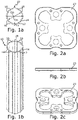
- FIGS 2a, 2b and 2c show different views of a coupling point - rosette 20.
- a coupling point - rosette is used at a node 22 to attach a crossbar with a bolt head 24 (see Figure 4a ).
- Figure 3a shows an isometric view of a scaffolding element 26 with a scaffold tube 10 at a node 22.
- a coupling point rosette 20 is attached at the node 22 .
- the scaffold tube 10 has stiffening grooves 12, 14, 16. The stiffening grooves increase the stability of the scaffold tube 10 in particular in the area of a node.
- the rosette 20 is shaped in such a way that it can be pushed onto the scaffold tube 10.
- Figure 3b shows a top view of a node 22.
- the rosette 20 touches the scaffolding tube 10 in the concavely shaped areas of the stiffening grooves 12, 14, 16. In the areas in which the scaffolding tube 10 is convexly curved outwards, the rosette 20 has recesses.
- Figure 4a shows the scaffolding element 26 in the area of the node 22.
- the scaffolding tube 10 has a first stiffening groove 12 which extends in the direction of the longitudinal axis 18 of the scaffolding tube 10 .
- the second stiffening groove 14 is formed directly next to the first stiffening groove 12 .
- Further stiffening grooves 16 are distributed around the circumference of the scaffold tube 10 . All stiffening grooves 12, 14, 16 run parallel to one another in the direction of the longitudinal axis 18 of the scaffold tube 10. Both shoulders 28 one The crossbar with the bolt head 24 rests against the scaffolding tube 10.
- Figure 4b shows a plan view of a node 22 in which a crossbar 24 is connected to a scaffolding tube 10 via a rosette 20 .
- the stiffening grooves 12, 14, 16 can be seen.
- the upper shoulder 28 of the crossbar with the bolt head 24 is in contact with the scaffold tube 10.
- the shoulder 28 rests against the scaffolding tube 10 at a convex point of the scaffolding tube 10 .
- the inner curvature of the rosette 20 rests against the scaffold tube 10 at concave points in the areas of the stiffening grooves 12 , 14 , 16 .
- figure 5 shows scaffolding 30 in the form of a shoring tower with a plurality of scaffolding elements 26 according to the invention, of which only a first scaffolding element 26 is provided with a reference number for reasons of clarity.
- Most of the framework elements 26 have at least one coupling point 20 .
- a cross bolt with a bolt head 24 can be arranged at the coupling point 20 .
- the scaffolding 30 has at least one first stiffening groove, which figure 5 is not visible due to the small representation of the scaffolding 30.
- FIG. 6 shows another scaffolding 30 in the form of a working scaffolding or facade scaffolding.
- the scaffolding 30 is in the form of a facade scaffolding.
- Analogously to scaffolding 30 according to figure 5 has the scaffolding 30 according to 6 a variety of framework elements 26 on.
- the scaffolding elements 26 are connected to one another via crossbars with a bolt head 24 , which are hooked into coupling points 20 , also called rosettes 20 .
- Stiffening grooves are in 6 not visible due to the small representation of scaffolding 30.
- the crossbars can be welded on one of the four sides of the scaffolding tube 10, with the rosette on the other three sides of the scaffolding tube 10 as a coupling point 20 each allows a connection with crossbars with bolt head 24.
Description
- Die Erfindung betrifft ein Gerüstelement für ein Baugerüst, wobei das Gerüstelement ein Gerüstrohr mit einem Knotenpunkt aufweist, wobei an dem Knotenpunkt ein Querriegel des Gerüstelements, insbesondere über einen Riegelkopf des Querriegels, mit dem Gerüstrohr verbunden ist und/oder eine Koppelstelle, z. B. in Form einer Lochscheibe, auch Rosette genannt, zur Anbindung eines solchen Querriegels ausgebildet ist. Die Erfindung betrifft weiterhin ein Baugerüst mit einem solchen Gerüstelement sowie ein Verfahren zum Herstellen eines Gerüstelements und eine Verwendung.
- Es ist bekannt, Baugerüste aus Gerüstelementen zusammenzusetzen, wobei die Gerüstelemente jeweils ein Gerüstrohr mit zumindest einem Knotenpunkt aufweisen. Im Bereich des Knotenpunkts ist die Belastung des Gerüstelements besonders hoch. Im Stand der Technik werden daher im Bereich des Knotenpunkts dicke Gerüstrohre und/oder Knotenbleche eingesetzt.
- Nachteilig an diesen bekannten Verstärkungen der Knotenpunkte ist das damit einhergehende hohe Gewicht des Gerüstelements. Da Gerüstelemente von Hand transportiert und montiert werden, besteht ein starkes Bedürfnis für Gewichtsreduktionen bei Gerüstelementen.
- Aus der
DE 10 2016 204 696 A1 ist es bekannt, ein Gerüstrohr an einem Knotenpunkt mit einer Versteifungsnut zu verstärken. Diese Versteifungsnut verstärkt das Gerüstrohr im Bereich eines Knotenpunkts. - Aus der
DE 198 44 610 A1 ist ferner ein Gerüstrohr mit Einbuchtungen zur Erhöhung der Lastaufnahmefähigkeit bekannt, wobei die Einbuchtung parallel zur Mittelachse des Gerüstrohrs verläuft. - Aus der
AT 360 733 B - Der
DE 295 00 479 U1 ist zudem ein Hohlprofilstab zu entnehmen, der ein im Umriss etwa kreisförmiges Rohrprofil mit über den Umfang in gleichmäßigen Umfangsabständen zueinander angeordneten, nach außen offenen T-Nuten aufweist. Der Nutgrund der T-Nuten ist zur Profilmitte hin konvex ausgewölbt. - Aufgabe der vorliegenden Erfindung ist, ein Gerüstelement zu schaffen, das besonders stabil und leicht ausgebildet ist und darüber hinaus kostengünstig fertigbar ist. Eine weitere Aufgabe der vorliegenden Erfindung ist es, ein Baugerüst mit einem solchen Gerüstelement zu schaffen und ein Verfahren zur Verfügung zu stellen, welches es ermöglicht, ein solches Gerüstrohr leicht herzustellen. Zudem soll noch eine einfache Lösung geschaffen werden, ein solch leichtes Gerüstrohr von marktüblichen Gerüstrohren, z. B. Rundrohren, zu unterscheiden, um leichte Erkennbarkeit herzustellen und Verwechslungen zu vermeiden.
- Die Aufgabe wird durch ein Gerüstelement mit den Merkmalen der unabhängigen Ansprüche 1, 10 und 14 gelöst. Die Unteransprüche und die im Folgenden beschriebenen Ausführungsbeispiele geben zweckmäßige Weiterbildungen an.
- Die erfindungsgemäße Aufgabe wird somit gelöst durch ein Gerüstelement mit einem Gerüstrohr und einem Knotenpunkt. Am Knotenpunkt kann ein Querriegel des Gerüstelements mit dem Gerüstrohr verbunden sein. Alternativ oder zusätzlich dazu kann am Knotenpunkt eine Koppelstelle zur Anbindung eines Querriegels ausgebildet sein. Zur Stabilisierung des Gerüstrohrs im Bereich des Knotenpunkts ist eine erste Versteifungsnut vorgesehen, die sich parallel einer Längsachse des Gerüstrohrs erstreckt. Die erste Versteifungsnut verringert den Innendurchmesser des Gerüstrohrs. Dabei entspricht die Innenkrümmung der ersten Versteifungsnut der Außenkrümmung des Gerüstrohrs.
- Die erste Versteifungsnut ist somit in Form einer Vertiefung des Gerüstrohrs ausgebildet. Eine solche Vertiefung, auch Sicke genannt, erhöht signifikant die Belastbarkeit des Gerüstrohrs im Bereich des Knotenpunkts. Das Gerüstrohr kann hierdurch dünnwandiger ausgebildet werden, wodurch es signifikant leichter transportierbar ist. Vorzugsweise weist das Gerüstrohr im Bereich des Knotenpunkts eine Wandstärke von 2 bis 4 mm auf. Idealerweise beträgt die Wandstärke im Bereich des Knotenpunkts 2 mm. Bevorzugt bleibt die Wandstärke des Gerüstrohrs über seinen gesamten Außendurchmesser gleich.
- Das Gerüstrohr ist vorzugsweise in Form eines Gerüststiels, d. h. zum vertikal ausgerichteten Einsatz, ausgebildet.
- Bei marktüblichen, insbesondere normierten, Gerüstrohren müssen diverse geometrische Rahmenbedingungen eingehalten werden, unter anderem eine Mindestwanddicke von 2,0 mm. Bei marktüblichen Gerüstrohren aus Stahl mit Außendurchmesser 48,3 mm ist zudem zur Einhaltung von Normen eine Mindestwanddicke von 2,7 mm vorgeschrieben. Bei marktüblichen Gerüstrohren aus Aluminium mit Außendurchmesser 48,3 mm ist zudem zur Einhaltung von Normen eine Mindestwanddicke von 3,0 mm vorgeschrieben.
- Durch die Formgebung der ersten Versteifungsnut, d. h. eine konkave Vertiefung im Gerüstrohr in seiner Längsrichtung, mit einer Krümmung nach innen, wie zuvor konvex nach außen, wird das Gerüstrohr in signifikanter Weise verstärkt. Dadurch, dass die Außenkrümmung des Rohrs sich in der Innenkrümmung der Sicke wiederfindet, ergibt sich eine Innenfläche der ersten Versteifungsnut, die der Außenfläche über einen gleichen Außenumfang des Gerüstrohrs entspricht. Der Außenumfang eines Gerüstrohrs zwischen 48 und 49 mm, bevorzugt 48,3 mm, kann somit als maximaler Außenradius und maximales Außenmaß beibehalten werden. An den Stellen der Versteifungsnuten ist das Außenmaß geringer.
- Durch die Formgebung der ersten Versteifungsnut, d. h. eine konkave Vertiefung im Gerüstrohr in seiner Längsrichtung, mit einer Krümmung nach innen, wie zuvor konvex nach außen, wird das Gerüstrohr in signifikanter Weise als nicht marktübliches und damit nicht normgemäßes Gerüstrohr erkennbar. Durch diese offensichtliche Unterscheidung kann somit auf die Einhaltung der Mindestwanddicke von 2,7 mm bzw. 3,00 mm verzichtet werden. Damit bekommt man die Freiheit, die Wanddicke auf ca. 2 mm bei Rohren mit einem Außendurchmesser von 48,3 mm herabzusetzen.
- Die erste Versteifungsnut erstreckt sich parallel zur zentrischen Längsachse des Gerüstrohrs. Die Größe der ersten Versteifungsnut wird dabei erfindungsgemäß so gewählt, dass sie in Umfangsrichtung des Gerüstrohrs einen Bereich des Außenumfangs des Gerüstrohrs einnimmt, der bezogen auf die zentrale Längsachse des Gerüstrohrs einem Winkelbereich zwischen 20° und 40°, bevorzugt 30°, entspricht. Bei den bevorzugten 30° entspricht dies einem Zwölftel des Außenumfangs des Gerüstrohrs. Der Winkelbereich von 20° und 40°, bevorzugt 30°, entspricht dabei einem Mittelpunktswinkel bezogen auf die zentrische Längsachse des Gerüstrohrs.
- Die Wahl eines Winkelbereichs zwischen 20° und 40°, bevorzugt 30°, ermöglicht die Anordnung mehrerer solcher Versteifungsnuten über den Außenumfang des Gerüstrohrs und damit eine erhöhte Verstärkungswirkung des Gerüstrohrs. Erfindungsgemäß weist das Gerüstrohr im Bereich des Knotenpunkts eine zweite Versteifungsnut parallel zur ersten Versteifungsnut auf. Auch bei der zweiten Versteifungsnut entspricht die Innenkrümmung der zweiten Versteifungsnut der Außenkrümmung des Gerüstrohrs, d. h. im Wesentlichen wird die konvexe Form des Gerüstrohrs im Bereich der zweiten Versteifungsnut konkav nach innen verformt.
- Ferner erfindungsgemäß nimmt die zweite Versteifungsnut einen zweiten Bereich des Außenumfangs des Gerüstrohrs ein, der einem Winkelbereich zwischen 20° und 40°, bevorzugt 30°, entspricht.
- In weiteren Ausführungsformen der vorliegenen Offenbarung ist die zweite Versteifungsnut gleich groß wie die erste Versteifungsnut, d. h. der erste Bereich ist gleich groß wie der zweite Bereich. Außerdem kann die zweite Versteifungsnut gleichartig wie die erste Versteifungsnut ausgebildet sein, insbesondere kann sie die gleiche Form aufweisen. Insbesondere kann die zweite Versteifungsnut gleich wie die erste Versteifungsnut ausgebildet sein. Der Fertigungsprozess wird dadurch vereinfacht.
- Des Weiteren erfindungsgemäß schließen der erste Bereich und der zweite Bereich unmittelbar aneinander an. Damit nehmen der erste und der zweite Bereich zusammen einen Bereich des Außenumfangs des Gerüstrohrs ein, der vorteilhafterweise zwischen 40° und 80°, bevorzugt 60°, entspricht. Dabei schließt dann erfindungsgemäß an die erste Versteifungsnut unmittelbar die zweite Versteifungsnut an, die gleichartig, insbesondere in gleicher Form oder gleich wie die erste Versteifungsnut, ausgebildet ist. An die zweite Versteifungsnut schließt dann erfindungsgemäß wiederum ein Stück des Gerüstrohrs an, das nicht konkav verformt ist, sondern die normale konvexe Außenkrümmung des Gerüstrohrs aufweist. In der bevorzugten Bereichsgröße von jeweils ca. 30° für den ersten und zweiten Bereich würde sich dann ein Bereich von weiteren 30° anschließen, der nicht durch eine Nut verändert ist. Somit weist in dieser Ausführungsform ein Viertel Außenumfang des Gerüstrohrs die Abfolge von erster Versteifungsnut, zweiter Versteifungsnut und konvexem Gerüstrohr auf. Bevorzugt setzt sich diese Symmetrie über den gesamten Außenumfang des Gerüstrohrs fort. Besonders bevorzugt ist das Gerüstrohr axialsymmetrisch zu seiner zentrischen Längsachse ausgebildet. Weiter bevorzugt ist das Gerüstelement axialsymmetrisch zur Längsachse des Gerüstelements ausgebildet.
- In einer bevorzugten Ausführungsform der vorliegenen Offenbarung befinden sich dann insgesamt acht Versteifungsnuten im Bereich von Knotenpunkten auf dem Außenumfang des Gerüstrohrs, welche bevorzugt alle acht gleichartig, insbesondere in gleicher Form oder gleich ausgebildet sind. Diese acht Versteifungsnuten nehmen vorteilhafterweise einen Anteil am Außenumfang des Gerüstrohrs zwischen 50% und 80%, bevorzugt zwei Drittel, ein.
- Das Gerüstelement kann mehrere Knotenpunkte aufweisen. Bevorzugt sind Versteifungsnuten im Bereich eines Knotenpunktes gleich ausgebildet. In einer besonders bevorzugten Ausführungsform sind die Versteifungsnuten eines Gerüstes im Bereich von mehreren seiner Knotenpunkte gleich ausgebildet.
- Um den Querriegel flexibel an das Gerüstrohr anbinden zu können, kann die Koppelstelle in Form einer Rosette zur Befestigung des Querriegels ausgebildet sein. Vorzugsweise ist der Querriegel Teil des in den Patentansprüchen beschriebenen Gerüstelements, wobei der Querriegel insbesondere reversibel lösbar in die Rosette eingeführt ist.
- Vorteilhafterweise entspricht die Innenkrümmung der Rosette der Außenkrümmung der ersten, der zweiten und der weiteren Versteifungsnuten des Gerüstrohres. Zumindest ist die Innenkontur der Rosette mit der Außenkrümmung des Gerüstrohrs kompatibel. Dabei entspricht die Innenkontur der Rosette der Innenkrümmung der Rosette und die Außenkontur des Gerüstrohres entspricht der Außenkrümmung des Gerüstrohrs im Bereich der Versteifungsnuten und außerhalb des Bereichs der Versteifungsnuten. Damit kann die definierte und fehlerfreie Einfädelung der Rosette an das Gerüstrohr sichergestellt werden.
- In weiteren Ausführungsformen der vorliegenen Offenbarung beträgt der Außendurchmesser des Gerüstrohrs zwischen 48,3 mm und 120 mm und/oder das Verhältnis des Innendurchmessers des Gerüstrohrs zum Außendurchmesser des Gerüstrohrs zwischen 0,75 und 0,95. Diese Maße ermöglichen flexibles Dimensionieren des Gerüstelementes bei gleichzeitiger Stabilität.
- Die erfindungsgemäße Aufgabe wird weiterhin gelöst durch ein Baugerüst mit einem zuvor beschriebenen Gerüstelement.
- Die erfindungsgemäße Aufgabe wird weiterhin gelöst durch ein Verfahren zur Herstellung eines zuvor beschriebenen Gerüstelements. Bei dem Verfahren werden die erste Versteifungsnut, die zweite Versteifungsnut und/oder die weiteren Versteifungsnuten in das Gerüstrohr durch Rollen gepresst. Dabei wird das Gerüstrohr in Längsachse durch Rollen nach innen verformt, sodass die Innenkrümmung der Versteifungsnuten der Außenkrümmung des Gerüstrohrs entspricht. Dieses Verfahren kann sowohl bei Aluminium als auch bei Stahlrohren Anwendung finden. In einer weiteren Ausführungsform, insbesondere bei Gerüstrohren aus Aluminium, werden die erste Versteifungsnut, die zweite Versteifungsnut und/oder die weiteren Versteifungsnuten durch Strangpress-Profilierung geformt.
- Ein weiterer Aspekt der vorliegenden Offenbarung betrifft die Verwendung eines oben und im Folgenden beschriebenen Gerüstelements in einem Baugerüst.
- Weitere Merkmale und Vorteile der Erfindung ergeben sich aus der nachfolgenden detaillierten Beschreibung von Ausführungsbeispielen der Erfindung, aus den Patentansprüchen sowie aus den Figuren der Zeichnung, wobei die Erfindung allein durch die beigefügten Patentansprüche definiert wird.
- Es zeigen:
- Fig. 1a
- eine Draufsicht in Richtung der Längsachse eines Gerüstrohrs;
- Fig. 1b
- eine isometrische Ansicht des Gerüstrohrs aus
Fig. 1a ; - Fig. 2a
- eine Draufsicht auf eine Koppelstelle-Rosette in Form einer Lochscheibe zur Befestigung eines Querriegels mit Riegelkopf;
- Fig. 2b
- eine Seitenansicht der Rosette aus
Fig. 2a ; - Fig. 2c
- eine isometrische Ansicht der Rosette aus den
Figuren 2a und 2b ; - Fig. 3a
- eine isometrische Ansicht eines Gerüstelements mit einem Gerüstrohr und mit einer Rosette als Koppelstelle;
- Fig. 3b
- eine Draufsicht in Richtung der zentrischen Längsachse des Gerüstelements gemäß
Fig. 3a ; - Fig. 4a
- eine Seitenansicht auf das Gerüstelement gemäß der
Figuren 3a und 3b mit einem Gerüstrohr, mit einer Rosette und einem an der Rosette befestigten Querriegel mit Riegelkopf; - Fig. 4b
- eine Draufsicht auf das Gerüstelement gemäß
Fig. 4a ; - Fig. 5
- eine isometrische Ansicht eines Baugerüsts mit erfindungsgemäßen Gerüstelementen und
- Fig. 6
- eine isometrische Ansicht eines weiteren Baugerüsts mit erfindungsgemäßen Gerüstelementen.
-
Fig. 1a zeigt eine Draufsicht auf ein Gerüstrohr 10 mit einer in Umfangsrichtung unveränderlichen Wanddicke t. Dargestellt ist eine erste Versteifungsnut 12, eine zweite Versteifungsnut 14 und sechs weitere Versteifungsnuten 16. Die erste Versteifungsnut 12, die zweite Versteifungsnut 14 und die sechs weiteren Versteifungsnuten 16 sind in identischer Form und Größe ausgebildet. Sie erstrecken sich parallel zu einer Längsachse des Gerüstrohrs 10 und sind symmetrisch über den Umfang des Gerüstrohrs 10 angeordnet. Das Gerüstrohr 10 ist konvex geformt und hat einen maximalen Außendurchmesser Da. Im Bereich der ersten Versteifungsnut 12, der zweiten Versteifungsnut 14 und der sechs weiteren Versteifungsnuten 16 ist das Gerüstrohr 10 konkav geformt und hat einen kleineren Außendurchmesser als an den konvexen Stellen. Im Bereich der Versteifungsnuten 12, 14, 16 hat das Gerüstrohr zudem einen minimalen Innendurchmesser Dn. Die konkave Form im Bereich der Versteifungsnuten 12, 14, 16 entsteht beispielsweise durch Rollen eines zylindrischen Rohres, insbesondere Aluminium oder Stahrohres. Die konkave Form im Bereich der Versteifungsnuten 12, 14, 16 kann beispielsweise auch durch Strangpress-Profilierung, insbesondere bei Aluminiumrohren, entstehen. In den konkaven Bereichen findet sich die Innenkrümmung des Gerüstrohrs als Außenkrümmung wieder. -
Fig. 1b zeigt eine isometrische Ansicht eines Gerüstrohrs 10. Es weist eine erste Versteifungsnut 12, eine zweite Versteifungsnut 14 und sechs weitere Versteifungsnuten 16 auf, die sich parallel zur zentrischen Längsachse 18 des Gerüstrohrs erstrecken. Das dargestellte Gerüstrohr 10 zeigt die Versteifungsnuten 12, 14, 16 über seine gesamte Länge. Es ist auch möglich, die Versteifungsnuten 12, 14, 16 in begrenzter Länge auszuführen, bevorzugt im Bereich einer Koppelstelle - Rosette 20 oder eines Knotenpunkts 22 (sieheFig. 3a ). - Die
Fig. 2a, 2b und 2c zeigen verschiedene Ansichten einer Koppelstelle - Rosette 20. Eine solche Koppelstelle - Rosette dient an einem Knotenpunkt 22 zur Befestigung eines Querriegels mit Riegelkopf 24 (sieheFig. 4a ). -
Fig. 3a zeigt eine isometrische Ansicht eines Gerüstelements 26 mit einem Gerüstrohr 10 an einem Knotenpunkt 22. An dem Knotenpunkt 22 ist eine Koppelstelle-Rosette 20 angebracht. Das Gerüstrohr 10 weist Versteifungsnuten 12, 14, 16 auf. Insbesondere im Bereich eines Knotenpunkts verstärken die Versteifungsnuten die Stabilität des Gerüstrohrs 10. Die Rosette 20 ist so geformt, dass sie auf das Gerüstrohr 10 aufgeschoben werden kann. -
Fig. 3b zeigt eine Draufsicht von oben auf einen Knotenpunkt 22. Zu sehen ist das Gerüstrohr 10 mit seiner ersten Versteifungsnut 12, seiner zweiten Versteifungsnut 14 und den weiteren Versteifungsnuten 16. Zu sehen ist ebenfalls die Rosette 20, die so geformt ist, dass sie in die Versteifungsnuten 12, 14, 16 eingreift und auf das Gerüstrohr 10 aufgeschoben werden kann. Die Rosette 20 berührt dabei das Gerüstrohr 10 in den konkav geformten Bereichen der Versteifungsnuten 12, 14, 16. In den Bereichen, in denen das Gerüstrohr 10 konvex nach außen gekrümmt ist, weist die Rosette 20 Ausnehmungen auf. -
Fig. 4a zeigt das Gerüstelement 26 im Bereich des Knotenpunkts 22. InFig. 4a ist weiter zu sehen, dass das Gerüstrohr 10 eine erste Versteifungsnut 12 aufweist, die sich in Richtung der Längsachse 18 des Gerüstrohrs 10 erstreckt. Direkt neben der ersten Versteifungsnut 12 ist die zweite Versteifungsnut 14 ausgebildet. Weitere Versteifungsnuten 16 sind um den Umfang des Gerüstrohrs 10 verteilt angeordnet. Alle Versteifungsnuten 12, 14, 16 verlaufen parallel zueinander in Richtung der Längsachse 18 des Gerüstrohrs 10. Beide Schultern 28 eines Querriegels mit Riegelkopf 24 liegen am Gerüstrohr 10 an. InFig. 4a ist ebenfalls zu sehen, dass der Querriegel mit Riegelkopf 24 über die Rosette 20 an dem Knotenpunkt 22 in Form einer Koppelstelle 20 mit dem Gerüstrohr 10 verbunden ist. Die beiden Schultern 28 des Querriegels mit Riegelkopf 24 liegen dabei im Bereich außerhalb von Versteifungsnuten am Gerüstrohr 10 an. -
Fig. 4b zeigt eine Draufsicht auf einen Knotenpunkt 22, bei dem ein Querriegel 24 über eine Rosette 20 mit einem Gerüstrohr 10 verbunden ist. Zu sehen sind die Versteifungsnuten 12, 14, 16. Zu sehen ist ebenfalls, dass die obere Schulter 28 des Querriegels mit Riegelkopf 24 an dem Gerüstrohr 10 anliegt. Die Schulter 28 liegt dabei an einer konvexen Stelle des Gerüstrohrs 10 an dem Gerüstrohr 10 an. Die Rosette 20 liegt mit ihrer Innenkrümmung an konkaven Stellen in Bereichen der Versteifungsnuten 12, 14, 16 am Gerüstrohr 10 an. -
Fig. 5 zeigt ein Baugerüst 30 in Form eines Traggerüstturmes mit mehreren erfindungsgemäßen Gerüstelementen 26, von denen aus Gründen der Übersichtlichkeit lediglich ein erstes Gerüstelement 26 mit einem Bezugszeichen versehen ist. Die Gerüstelemente 26 weisen mehrheitlich zumindest eine Koppelstelle 20 auf. An der Koppelstelle 20 ist ein Querriegel mit Riegelkopf 24 anordenbar. Im Bereich der Koppelstelle 20 weist das Baugerüst 30 zumindest eine erste Versteifungsnut auf, die inFig. 5 aufgrund der kleinen Darstellung des Baugerüsts 30 nicht sichtbar ist. -
Fig. 6 zeigt ein weiteres Baugerüst 30 in Form eines Arbeits- bzw. Fassadengerüstes. Das Baugerüst 30 ist in Form eines Fassadengerüsts ausgebildet. Analog zum Baugerüst 30 gemäßFig. 5 weist das Baugerüst 30 gemäßFig. 6 eine Vielzahl von Gerüstelementen 26 auf. Die Gerüstelemente 26 sind über Querriegel mit Riegelkopf 24 miteinander verbunden, die in Koppelstellen 20, auch Rosetten 20 genannt, eingehängt sind. Versteifungsnuten sind inFig. 6 aufgrund der kleinen Darstellung des Baugerüsts 30 nicht sichtbar. Bei dieser Form des Baugerüstes können auf einer der vier Seiten des Gerüstrohres 10 die Querriegel angeschweißt werden, wobei an den anderen drei Seiten des Gerüstrohres 10 die Rosette als Koppelstelle 20 jeweils eine Verbindung mit Querriegeln mit Riegelkopf 24 ermöglicht.
Claims (14)
- Gerüstelement (26) für ein Baugerüst (30), wobei das Gerüstelement (26) ein Gerüstrohr (10) mit einer konvexen Außenkrümmung und einem Knotenpunkt (22) aufweist, wobei an dem Knotenpunkt (22)a) ein Querriegel (24) des Gerüstelements (26) mit dem Gerüstrohr (10) verbunden ist und/oderb) eine Koppelstelle (20) zur Anbindung eines Querriegels ausgebildet ist, wobei das Gerüstrohr (10) im Bereich des Knotenpunkts (22) eine erste Versteifungsnut (12) aufweist, welche sich parallel zur zentrischen Längsachse (18) des Gerüstrohrs (10) als konkave Vertiefung mit einer Krümmung nach innen wie zuvor konvex nach außen erstreckt, so dass die Innenkrümmung der ersten Versteifungsnut (12) der Außenkrümmung des Gerüstrohrs (10) entspricht,wobei das Gerüstrohr (10) im Bereich des Knotenpunkts (22) eine zweite Versteifungsnut (14) parallel zur ersten Versteifungsnut (12) aufweist, wobei die Innenkrümmung der zweiten Versteifungsnut der Außenkrümmung des Gerüstrohrs (10) entspricht,wobei die erste Versteifungsnut (12) in Umfangsrichtung des Gerüstrohrs (10) einen ersten Bereich des Außenumfangs des Gerüstrohrs (10) einnimmt, der einem Winkelbereich bezogen auf die zentrische Längsachse (18) des Gerüstrohrs (10) zwischen 20° und 40°, bevorzugt 30°, entspricht,wobei die zweite Versteifungsnut einen zweiten Bereich des Außenumfangs des Gerüstrohrs (10) einnimmt, der einem Winkelbereich zwischen 20° und 40°, bevorzugt 30°, entspricht,wobei der erste Bereich und der zweite Bereich , und damit die erste und die zweite Versteifungsnut, unmittelbar aneinander anschließen, wobei die erste und die zweite Versteifungsnut gleichartig ausgebildet sind,und wobei an die zweite Versteifungsnut ein Stück des Gerüstrohrs anschließt, das nicht konkav verformt ist, sondern die normale konvexe Außenkrümmung des Gerüstrohrs aufweist.
- Gerüstelement nach Anspruch 1, wobei sich die erste Versteifungsnut (12) im Wesentlichen über die ganze Länge des Gerüstrohrs (10) erstreckt.
- Gerüstelement nach Anspruch 1 oder 2, wobei die zweite Versteifungsnut einen zweiten Bereich des Außenumfangs des Gerüstrohrs (10) einnimmt, wobei der zweite Bereich gleich groß ist wie der erste Bereich.
- Gerüstelement nach einem der vorhergehenden Ansprüche, wobei die zweite Versteifungsnut (14) gleichartig wie die erste Versteifungsnut (12) ausgebildet ist.
- Gerüstelement nach einem der vorhergehenden Ansprüche, wobei sich auf dem Außenumfang des Gerüstrohrs (10) eine bis sechs weitere Versteifungsnuten (16) befinden, welche gleichartig wie die erste Versteifungsnut (12) und die zweite Versteifungsnut (14) ausgebildet sind.
- Gerüstelement nach Anspruch 5, wobei die erste Versteifungsnut (12), die zweite Versteifungsnut (14) und die weiteren Versteifungsnuten (16) symmetrisch über den Außenumfang des Gerüstrohrs (10) verteilt sind.
- Gerüstelement nach einem der Ansprüchen 5 oder 6, wobei die Koppelstelle (20) als Rosette ausgebildet ist, wobei die Innenkrümmung der Rosette der Außenkrümmung der ersten, der zweiten und der weiteren Versteifungsnuten (12, 14, 16) des Gerüstrohres (10) entspricht.
- Gerüstelement nach einem der vorherigen Ansprüche, wobei der Außendurchmesser (Da) des Gerüstrohrs (10) zwischen 48,3 mm und 120 mm beträgt und/oder
das Verhältnis des Innendurchmessers (Dn) des Gerüstrohrs (10) zum Außendurchmesser (Da) des Gerüstrohrs (10) zwischen 0,75 und 0,95 beträgt. - Baugerüst (30) mit einem Gerüstelement (26) nach einem der Ansprüche 1 bis 8.
- Verfahren zum Herstellen eines eines Gerüstelements (26) nach einem der Ansprüche 1 bis 8, wobei die Außenkrümmung eines Gerüstrohrs (10) in einem in Umfangsrichtung des Gerüstrohres (10) ersten Bereich des Außenumfangs, der einem Winkelbereich bezogen auf die zentrische Längsachse (18) Gerüstrohrs (10) von 20° bis 40° Grad, bevorzugt 30°, entspricht, in Richtung parallel zur zentrischen Längsachse (18) des Gerüstrohrs durch Rollen nach innen verformt wird oder, insbesondere bei Gerüstrohren aus Aluminium, durch Strangpress-Profilierung geformt wird.
- Verfahren zum Herstellen eines Gerüstelements (26) nach Anspruch 10, wobei der Außendurchmesser (Da) des Gerüstrohrs (10) zwischen 48,3 mm und 120 mm beträgt und/oder das Verhältnis des Innendurchmessers (Dn) des Gerüstrohrs (10) zum Außendurchmesser (Da) des Gerüstrohrs (10) zwischen 0,75 und 0,95 beträgt.
- Verfahren zum Herstellen eines Gerüstelements (26) nach Anspruch 10 oder 11,wobei die Außenkrümmung des Gerüstrohrs (10) in Richtung parallel zur zentrischen Längsachse (18) des Gerüstrohrs (10) durch Rollen nach innen verformt wird,wobei ein Stahlrohr, insbesondere mit Außendurchmesser (Da) 48,3 mm und einer Wanddicke (t) von ca. 2,0 bis ca. 2,6 mm, verformt wird undwobei in Umfangsrichtung mehrere Bereiche, insbesondere 8 Bereiche, des Gerüstrohrs (10) verformt werden.
- Verfahren zum Herstellen eines Gerüstelements (26) nach einem der Ansprüche 10 bis 12, dadurch gekennzeichnet, dass die Außenkrümmung des Gerüstrohrs (10) in Richtung parallel zur zentrischen Längsachse (18) des Gerüstrohrs (10) durch Strangpress-Profilierung geformt wird, wobei ein Aluminiumrohr, insbesondere mit Außendurchmesser Da=48,3 mm und einer Wanddicke (t) von ca. 2,0 bis ca. 2,6 mm, geformt wird und wobei in Umfangsrichtung mehrere Bereiche, insbesondere 8 Bereiche, des Gerüstrohrs (10) geformt werden.
- Verwendung eines Gerüstelements (26) nach einem der Ansprüche 1 bis 8 in einem Baugerüst (30).
Applications Claiming Priority (1)
| Application Number | Priority Date | Filing Date | Title |
|---|---|---|---|
| DE102019200770.8A DE102019200770A1 (de) | 2019-01-23 | 2019-01-23 | Gerüstelement mit einem Knotenpunkt, Baugerüst mit einem solchen Gerüstelement und Verfahren zum Herstellen eines Gerüstelements |
Publications (3)
| Publication Number | Publication Date |
|---|---|
| EP3686374A1 EP3686374A1 (de) | 2020-07-29 |
| EP3686374B1 true EP3686374B1 (de) | 2022-05-11 |
| EP3686374B8 EP3686374B8 (de) | 2022-06-29 |
Family
ID=69177094
Family Applications (1)
| Application Number | Title | Priority Date | Filing Date |
|---|---|---|---|
| EP20152458.4A Active EP3686374B8 (de) | 2019-01-23 | 2020-01-17 | Gerüstelement mit einem knotenpunkt, baugerüst mit einem solchen gerüstelement und verfahren zum herstellen eines gerüstelements |
Country Status (4)
| Country | Link |
|---|---|
| EP (1) | EP3686374B8 (de) |
| DE (1) | DE102019200770A1 (de) |
| ES (1) | ES2924841T3 (de) |
| PL (1) | PL3686374T3 (de) |
Family Cites Families (6)
| Publication number | Priority date | Publication date | Assignee | Title |
|---|---|---|---|---|
| FR2421252A1 (fr) * | 1978-03-29 | 1979-10-26 | Somefran | Dispositif de raccordement de deux elements tubulaires, et elements d'echafaudage correspondants a cadres prefabriques |
| DE29500479U1 (de) * | 1995-01-13 | 1995-08-10 | Odenthal Barbara | Hohlprofilstab |
| DE19844610A1 (de) * | 1998-09-29 | 2000-03-30 | Plettac Ag | Gerüstrohr mit Einbuchtungen zur Erhöhung der Lastaufnahmefähigkeit |
| DE10355495A1 (de) * | 2003-11-27 | 2005-07-21 | Peri Gmbh | Zerlegbares Gerüst |
| DE102016204696A1 (de) | 2016-03-22 | 2017-09-28 | Peri Gmbh | Gerüstelement mit einem Knotenpunkt und Baugerüst mit einem solchen Gerüstelement |
| DE102016208739A1 (de) * | 2016-05-20 | 2017-11-23 | Peri Gmbh | Gerüststiel sowie Verfahren zum Herstellen eines Gerüststiels |
-
2019
- 2019-01-23 DE DE102019200770.8A patent/DE102019200770A1/de active Pending
-
2020
- 2020-01-17 PL PL20152458.4T patent/PL3686374T3/pl unknown
- 2020-01-17 EP EP20152458.4A patent/EP3686374B8/de active Active
- 2020-01-17 ES ES20152458T patent/ES2924841T3/es active Active
Also Published As
| Publication number | Publication date |
|---|---|
| PL3686374T3 (pl) | 2022-09-05 |
| DE102019200770A1 (de) | 2020-07-23 |
| ES2924841T3 (es) | 2022-10-11 |
| EP3686374A1 (de) | 2020-07-29 |
| EP3686374B8 (de) | 2022-06-29 |
Similar Documents
| Publication | Publication Date | Title |
|---|---|---|
| EP0393090B1 (de) | Bausatz zur herstellung von tragwerken | |
| EP2521829B1 (de) | Gerüststiel | |
| WO2000034670A1 (de) | T-verbindung zweier profilstäbe | |
| DE3033909C2 (de) | Verbindungselement | |
| EP2390439A2 (de) | Modulgerüst mit biegsteif anliegenden Rohrriegelanschlüssen | |
| EP1359331B1 (de) | Schienenmutterprofil | |
| EP3686374B1 (de) | Gerüstelement mit einem knotenpunkt, baugerüst mit einem solchen gerüstelement und verfahren zum herstellen eines gerüstelements | |
| WO2018099837A1 (de) | Gerüstelement, gerüst mit einem solchen gerüstelement und verfahren zur montage des gerüsts | |
| EP1138849A2 (de) | Rohrelement | |
| EP1983128B1 (de) | Gerüststellrahmen und Verfahren zur Herstellung einer Gerüstrahmenanordnung aus wenigstens einem Gerüststellrahmen | |
| WO2023180121A1 (de) | Vertikalstiel für ein gerüst, gerüst sowie verfahren zur herstellung eines vertikalstiels | |
| EP0610479B1 (de) | Ankerschiene für die bautechnik | |
| DE2727448A1 (de) | Rohrgeruest | |
| EP1381739B1 (de) | T-verbindung zweier profilstäbe | |
| DE3513553A1 (de) | Zerlegbares regal, insbesondere palettenregal | |
| DE10112370A1 (de) | Hohlprofilstab für ein Gerüstsystem | |
| EP1516097B1 (de) | Verbindungs- und umlenkelement für zugbänder bei einem pneumatischen bauelement | |
| DE10111279A1 (de) | Gerüstrohr | |
| EP0805281A1 (de) | Verbindungsanordnung mit zwei stabförmigen Profilen | |
| DE10159506B4 (de) | Steckverbindung für Gerüste | |
| EP3591140B1 (de) | Schwerlastriegel, gerüst, verfahren zur herstellung eines schwerlastriegels, verfahren zur herstellung eines gerüsts | |
| WO2017198855A1 (de) | Gerüststiel sowie verfahren zum herstellen eines gerüststiels | |
| AT142273B (de) | Stahlrohrleiter u. dgl. | |
| DE4414759A1 (de) | Gestell für die Lagerung von länglichen Gegenständen sowie Profilelement für den Aufbau eines solchen Gestells | |
| DE10242582B4 (de) | Verbinder zur Herstellung von Stossverbindungen von Vierkant-Hohlprofilen |
Legal Events
| Date | Code | Title | Description |
|---|---|---|---|
| PUAI | Public reference made under article 153(3) epc to a published international application that has entered the european phase |
Free format text: ORIGINAL CODE: 0009012 |
|
| STAA | Information on the status of an ep patent application or granted ep patent |
Free format text: STATUS: THE APPLICATION HAS BEEN PUBLISHED |
|
| AK | Designated contracting states |
Kind code of ref document: A1 Designated state(s): AL AT BE BG CH CY CZ DE DK EE ES FI FR GB GR HR HU IE IS IT LI LT LU LV MC MK MT NL NO PL PT RO RS SE SI SK SM TR |
|
| AX | Request for extension of the european patent |
Extension state: BA ME |
|
| STAA | Information on the status of an ep patent application or granted ep patent |
Free format text: STATUS: REQUEST FOR EXAMINATION WAS MADE |
|
| 17P | Request for examination filed |
Effective date: 20210127 |
|
| RBV | Designated contracting states (corrected) |
Designated state(s): AL AT BE BG CH CY CZ DE DK EE ES FI FR GB GR HR HU IE IS IT LI LT LU LV MC MK MT NL NO PL PT RO RS SE SI SK SM TR |
|
| STAA | Information on the status of an ep patent application or granted ep patent |
Free format text: STATUS: EXAMINATION IS IN PROGRESS |
|
| 17Q | First examination report despatched |
Effective date: 20210521 |
|
| GRAP | Despatch of communication of intention to grant a patent |
Free format text: ORIGINAL CODE: EPIDOSNIGR1 |
|
| STAA | Information on the status of an ep patent application or granted ep patent |
Free format text: STATUS: GRANT OF PATENT IS INTENDED |
|
| INTG | Intention to grant announced |
Effective date: 20220120 |
|
| GRAS | Grant fee paid |
Free format text: ORIGINAL CODE: EPIDOSNIGR3 |
|
| GRAA | (expected) grant |
Free format text: ORIGINAL CODE: 0009210 |
|
| STAA | Information on the status of an ep patent application or granted ep patent |
Free format text: STATUS: THE PATENT HAS BEEN GRANTED |
|
| AK | Designated contracting states |
Kind code of ref document: B1 Designated state(s): AL AT BE BG CH CY CZ DE DK EE ES FI FR GB GR HR HU IE IS IT LI LT LU LV MC MK MT NL NO PL PT RO RS SE SI SK SM TR |
|
| REG | Reference to a national code |
Ref country code: GB Ref legal event code: FG4D Free format text: NOT ENGLISH |
|
| REG | Reference to a national code |
Ref country code: CH Ref legal event code: EP |
|
| REG | Reference to a national code |
Ref country code: AT Ref legal event code: REF Ref document number: 1491534 Country of ref document: AT Kind code of ref document: T Effective date: 20220515 |
|
| REG | Reference to a national code |
Ref country code: DE Ref legal event code: R096 Ref document number: 502020001073 Country of ref document: DE |
|
| REG | Reference to a national code |
Ref country code: IE Ref legal event code: FG4D Free format text: LANGUAGE OF EP DOCUMENT: GERMAN |
|
| REG | Reference to a national code |
Ref country code: CH Ref legal event code: PK Free format text: BERICHTIGUNG B8 |
|
| RAP2 | Party data changed (patent owner data changed or rights of a patent transferred) |
Owner name: PERI SE |
|
| REG | Reference to a national code |
Ref country code: SE Ref legal event code: TRGR |
|
| REG | Reference to a national code |
Ref country code: LT Ref legal event code: MG9D |
|
| REG | Reference to a national code |
Ref country code: NL Ref legal event code: MP Effective date: 20220511 |
|
| REG | Reference to a national code |
Ref country code: ES Ref legal event code: FG2A Ref document number: 2924841 Country of ref document: ES Kind code of ref document: T3 Effective date: 20221011 |
|
| PG25 | Lapsed in a contracting state [announced via postgrant information from national office to epo] |
Ref country code: PT Free format text: LAPSE BECAUSE OF FAILURE TO SUBMIT A TRANSLATION OF THE DESCRIPTION OR TO PAY THE FEE WITHIN THE PRESCRIBED TIME-LIMIT Effective date: 20220912 Ref country code: NO Free format text: LAPSE BECAUSE OF FAILURE TO SUBMIT A TRANSLATION OF THE DESCRIPTION OR TO PAY THE FEE WITHIN THE PRESCRIBED TIME-LIMIT Effective date: 20220811 Ref country code: NL Free format text: LAPSE BECAUSE OF FAILURE TO SUBMIT A TRANSLATION OF THE DESCRIPTION OR TO PAY THE FEE WITHIN THE PRESCRIBED TIME-LIMIT Effective date: 20220511 Ref country code: LT Free format text: LAPSE BECAUSE OF FAILURE TO SUBMIT A TRANSLATION OF THE DESCRIPTION OR TO PAY THE FEE WITHIN THE PRESCRIBED TIME-LIMIT Effective date: 20220511 Ref country code: HR Free format text: LAPSE BECAUSE OF FAILURE TO SUBMIT A TRANSLATION OF THE DESCRIPTION OR TO PAY THE FEE WITHIN THE PRESCRIBED TIME-LIMIT Effective date: 20220511 Ref country code: GR Free format text: LAPSE BECAUSE OF FAILURE TO SUBMIT A TRANSLATION OF THE DESCRIPTION OR TO PAY THE FEE WITHIN THE PRESCRIBED TIME-LIMIT Effective date: 20220812 Ref country code: FI Free format text: LAPSE BECAUSE OF FAILURE TO SUBMIT A TRANSLATION OF THE DESCRIPTION OR TO PAY THE FEE WITHIN THE PRESCRIBED TIME-LIMIT Effective date: 20220511 Ref country code: BG Free format text: LAPSE BECAUSE OF FAILURE TO SUBMIT A TRANSLATION OF THE DESCRIPTION OR TO PAY THE FEE WITHIN THE PRESCRIBED TIME-LIMIT Effective date: 20220811 |
|
| PG25 | Lapsed in a contracting state [announced via postgrant information from national office to epo] |
Ref country code: RS Free format text: LAPSE BECAUSE OF FAILURE TO SUBMIT A TRANSLATION OF THE DESCRIPTION OR TO PAY THE FEE WITHIN THE PRESCRIBED TIME-LIMIT Effective date: 20220511 Ref country code: LV Free format text: LAPSE BECAUSE OF FAILURE TO SUBMIT A TRANSLATION OF THE DESCRIPTION OR TO PAY THE FEE WITHIN THE PRESCRIBED TIME-LIMIT Effective date: 20220511 Ref country code: IS Free format text: LAPSE BECAUSE OF FAILURE TO SUBMIT A TRANSLATION OF THE DESCRIPTION OR TO PAY THE FEE WITHIN THE PRESCRIBED TIME-LIMIT Effective date: 20220911 |
|
| PG25 | Lapsed in a contracting state [announced via postgrant information from national office to epo] |
Ref country code: SM Free format text: LAPSE BECAUSE OF FAILURE TO SUBMIT A TRANSLATION OF THE DESCRIPTION OR TO PAY THE FEE WITHIN THE PRESCRIBED TIME-LIMIT Effective date: 20220511 Ref country code: SK Free format text: LAPSE BECAUSE OF FAILURE TO SUBMIT A TRANSLATION OF THE DESCRIPTION OR TO PAY THE FEE WITHIN THE PRESCRIBED TIME-LIMIT Effective date: 20220511 Ref country code: RO Free format text: LAPSE BECAUSE OF FAILURE TO SUBMIT A TRANSLATION OF THE DESCRIPTION OR TO PAY THE FEE WITHIN THE PRESCRIBED TIME-LIMIT Effective date: 20220511 Ref country code: EE Free format text: LAPSE BECAUSE OF FAILURE TO SUBMIT A TRANSLATION OF THE DESCRIPTION OR TO PAY THE FEE WITHIN THE PRESCRIBED TIME-LIMIT Effective date: 20220511 Ref country code: DK Free format text: LAPSE BECAUSE OF FAILURE TO SUBMIT A TRANSLATION OF THE DESCRIPTION OR TO PAY THE FEE WITHIN THE PRESCRIBED TIME-LIMIT Effective date: 20220511 Ref country code: CZ Free format text: LAPSE BECAUSE OF FAILURE TO SUBMIT A TRANSLATION OF THE DESCRIPTION OR TO PAY THE FEE WITHIN THE PRESCRIBED TIME-LIMIT Effective date: 20220511 |
|
| PGFP | Annual fee paid to national office [announced via postgrant information from national office to epo] |
Ref country code: SE Payment date: 20221221 Year of fee payment: 4 Ref country code: FR Payment date: 20221220 Year of fee payment: 4 |
|
| REG | Reference to a national code |
Ref country code: DE Ref legal event code: R097 Ref document number: 502020001073 Country of ref document: DE |
|
| PLBE | No opposition filed within time limit |
Free format text: ORIGINAL CODE: 0009261 |
|
| STAA | Information on the status of an ep patent application or granted ep patent |
Free format text: STATUS: NO OPPOSITION FILED WITHIN TIME LIMIT |
|
| PG25 | Lapsed in a contracting state [announced via postgrant information from national office to epo] |
Ref country code: AL Free format text: LAPSE BECAUSE OF FAILURE TO SUBMIT A TRANSLATION OF THE DESCRIPTION OR TO PAY THE FEE WITHIN THE PRESCRIBED TIME-LIMIT Effective date: 20220511 |
|
| 26N | No opposition filed |
Effective date: 20230214 |
|
| PGFP | Annual fee paid to national office [announced via postgrant information from national office to epo] |
Ref country code: ES Payment date: 20230203 Year of fee payment: 4 |
|
| PG25 | Lapsed in a contracting state [announced via postgrant information from national office to epo] |
Ref country code: SI Free format text: LAPSE BECAUSE OF FAILURE TO SUBMIT A TRANSLATION OF THE DESCRIPTION OR TO PAY THE FEE WITHIN THE PRESCRIBED TIME-LIMIT Effective date: 20220511 |
|
| PGFP | Annual fee paid to national office [announced via postgrant information from national office to epo] |
Ref country code: TR Payment date: 20230110 Year of fee payment: 4 Ref country code: DE Payment date: 20221220 Year of fee payment: 4 |
|
| REG | Reference to a national code |
Ref country code: DE Ref legal event code: R081 Ref document number: 502020001073 Country of ref document: DE Owner name: PERI SE, DE Free format text: FORMER OWNER: PERI GMBH, 89264 WEISSENHORN, DE |
|
| P01 | Opt-out of the competence of the unified patent court (upc) registered |
Effective date: 20230602 |
|
| REG | Reference to a national code |
Ref country code: CH Ref legal event code: PL |
|
| PG25 | Lapsed in a contracting state [announced via postgrant information from national office to epo] |
Ref country code: LU Free format text: LAPSE BECAUSE OF NON-PAYMENT OF DUE FEES Effective date: 20230117 |
|
| REG | Reference to a national code |
Ref country code: BE Ref legal event code: MM Effective date: 20230131 |
|
| PG25 | Lapsed in a contracting state [announced via postgrant information from national office to epo] |
Ref country code: LI Free format text: LAPSE BECAUSE OF NON-PAYMENT OF DUE FEES Effective date: 20230131 Ref country code: CH Free format text: LAPSE BECAUSE OF NON-PAYMENT OF DUE FEES Effective date: 20230131 |
|
| PG25 | Lapsed in a contracting state [announced via postgrant information from national office to epo] |
Ref country code: BE Free format text: LAPSE BECAUSE OF NON-PAYMENT OF DUE FEES Effective date: 20230131 |
|
| PGFP | Annual fee paid to national office [announced via postgrant information from national office to epo] |
Ref country code: PL Payment date: 20221215 Year of fee payment: 4 |
|
| PG25 | Lapsed in a contracting state [announced via postgrant information from national office to epo] |
Ref country code: IT Free format text: LAPSE BECAUSE OF FAILURE TO SUBMIT A TRANSLATION OF THE DESCRIPTION OR TO PAY THE FEE WITHIN THE PRESCRIBED TIME-LIMIT Effective date: 20220511 Ref country code: IE Free format text: LAPSE BECAUSE OF NON-PAYMENT OF DUE FEES Effective date: 20230117 |
|
| PGFP | Annual fee paid to national office [announced via postgrant information from national office to epo] |
Ref country code: PL Payment date: 20231208 Year of fee payment: 5 |
|
| PGFP | Annual fee paid to national office [announced via postgrant information from national office to epo] |
Ref country code: ES Payment date: 20240202 Year of fee payment: 5 |