EP3685933B1 - Procédé de traitement de plaque d'acier - Google Patents
Procédé de traitement de plaque d'acier Download PDFInfo
- Publication number
- EP3685933B1 EP3685933B1 EP20150106.1A EP20150106A EP3685933B1 EP 3685933 B1 EP3685933 B1 EP 3685933B1 EP 20150106 A EP20150106 A EP 20150106A EP 3685933 B1 EP3685933 B1 EP 3685933B1
- Authority
- EP
- European Patent Office
- Prior art keywords
- heating
- steel plate
- electrode
- trim edge
- hole
- Prior art date
- Legal status (The legal status is an assumption and is not a legal conclusion. Google has not performed a legal analysis and makes no representation as to the accuracy of the status listed.)
- Active
Links
- 229910000831 Steel Inorganic materials 0.000 title claims description 92
- 239000010959 steel Substances 0.000 title claims description 92
- 238000000034 method Methods 0.000 title claims description 17
- 238000012545 processing Methods 0.000 title claims description 7
- 238000010438 heat treatment Methods 0.000 claims description 142
- 238000004080 punching Methods 0.000 claims description 26
- 238000003672 processing method Methods 0.000 description 11
- 238000012360 testing method Methods 0.000 description 10
- 230000002093 peripheral effect Effects 0.000 description 8
- 238000001816 cooling Methods 0.000 description 5
- 238000013021 overheating Methods 0.000 description 5
- 238000005336 cracking Methods 0.000 description 4
- 238000010586 diagram Methods 0.000 description 4
- 230000006872 improvement Effects 0.000 description 2
- 239000012212 insulator Substances 0.000 description 2
- 239000000463 material Substances 0.000 description 2
- 230000008569 process Effects 0.000 description 2
- 0 CC*(C)C1SC=C*=C1 Chemical compound CC*(C)C1SC=C*=C1 0.000 description 1
- RYGMFSIKBFXOCR-UHFFFAOYSA-N Copper Chemical compound [Cu] RYGMFSIKBFXOCR-UHFFFAOYSA-N 0.000 description 1
- 229910001335 Galvanized steel Inorganic materials 0.000 description 1
- 229910001566 austenite Inorganic materials 0.000 description 1
- 230000008859 change Effects 0.000 description 1
- 229910052802 copper Inorganic materials 0.000 description 1
- 239000010949 copper Substances 0.000 description 1
- 238000005520 cutting process Methods 0.000 description 1
- 230000007423 decrease Effects 0.000 description 1
- 230000000694 effects Effects 0.000 description 1
- 239000008397 galvanized steel Substances 0.000 description 1
- 238000004519 manufacturing process Methods 0.000 description 1
- 238000012986 modification Methods 0.000 description 1
- 230000004048 modification Effects 0.000 description 1
- 239000000725 suspension Substances 0.000 description 1
- 238000012546 transfer Methods 0.000 description 1
- 230000009466 transformation Effects 0.000 description 1
- XLYOFNOQVPJJNP-UHFFFAOYSA-N water Substances O XLYOFNOQVPJJNP-UHFFFAOYSA-N 0.000 description 1
Images


Classifications
-
- C—CHEMISTRY; METALLURGY
- C21—METALLURGY OF IRON
- C21D—MODIFYING THE PHYSICAL STRUCTURE OF FERROUS METALS; GENERAL DEVICES FOR HEAT TREATMENT OF FERROUS OR NON-FERROUS METALS OR ALLOYS; MAKING METAL MALLEABLE, e.g. BY DECARBURISATION OR TEMPERING
- C21D1/00—General methods or devices for heat treatment, e.g. annealing, hardening, quenching or tempering
- C21D1/34—Methods of heating
- C21D1/42—Induction heating
-
- C—CHEMISTRY; METALLURGY
- C21—METALLURGY OF IRON
- C21D—MODIFYING THE PHYSICAL STRUCTURE OF FERROUS METALS; GENERAL DEVICES FOR HEAT TREATMENT OF FERROUS OR NON-FERROUS METALS OR ALLOYS; MAKING METAL MALLEABLE, e.g. BY DECARBURISATION OR TEMPERING
- C21D9/00—Heat treatment, e.g. annealing, hardening, quenching or tempering, adapted for particular articles; Furnaces therefor
- C21D9/0081—Heat treatment, e.g. annealing, hardening, quenching or tempering, adapted for particular articles; Furnaces therefor for slabs; for billets
-
- B—PERFORMING OPERATIONS; TRANSPORTING
- B21—MECHANICAL METAL-WORKING WITHOUT ESSENTIALLY REMOVING MATERIAL; PUNCHING METAL
- B21D—WORKING OR PROCESSING OF SHEET METAL OR METAL TUBES, RODS OR PROFILES WITHOUT ESSENTIALLY REMOVING MATERIAL; PUNCHING METAL
- B21D19/00—Flanging or other edge treatment, e.g. of tubes
- B21D19/005—Edge deburring or smoothing
-
- B—PERFORMING OPERATIONS; TRANSPORTING
- B21—MECHANICAL METAL-WORKING WITHOUT ESSENTIALLY REMOVING MATERIAL; PUNCHING METAL
- B21D—WORKING OR PROCESSING OF SHEET METAL OR METAL TUBES, RODS OR PROFILES WITHOUT ESSENTIALLY REMOVING MATERIAL; PUNCHING METAL
- B21D19/00—Flanging or other edge treatment, e.g. of tubes
- B21D19/08—Flanging or other edge treatment, e.g. of tubes by single or successive action of pressing tools, e.g. vice jaws
- B21D19/088—Flanging or other edge treatment, e.g. of tubes by single or successive action of pressing tools, e.g. vice jaws for flanging holes
-
- B—PERFORMING OPERATIONS; TRANSPORTING
- B21—MECHANICAL METAL-WORKING WITHOUT ESSENTIALLY REMOVING MATERIAL; PUNCHING METAL
- B21D—WORKING OR PROCESSING OF SHEET METAL OR METAL TUBES, RODS OR PROFILES WITHOUT ESSENTIALLY REMOVING MATERIAL; PUNCHING METAL
- B21D28/00—Shaping by press-cutting; Perforating
- B21D28/02—Punching blanks or articles with or without obtaining scrap; Notching
-
- B—PERFORMING OPERATIONS; TRANSPORTING
- B21—MECHANICAL METAL-WORKING WITHOUT ESSENTIALLY REMOVING MATERIAL; PUNCHING METAL
- B21D—WORKING OR PROCESSING OF SHEET METAL OR METAL TUBES, RODS OR PROFILES WITHOUT ESSENTIALLY REMOVING MATERIAL; PUNCHING METAL
- B21D28/00—Shaping by press-cutting; Perforating
- B21D28/24—Perforating, i.e. punching holes
- B21D28/26—Perforating, i.e. punching holes in sheets or flat parts
-
- B—PERFORMING OPERATIONS; TRANSPORTING
- B21—MECHANICAL METAL-WORKING WITHOUT ESSENTIALLY REMOVING MATERIAL; PUNCHING METAL
- B21D—WORKING OR PROCESSING OF SHEET METAL OR METAL TUBES, RODS OR PROFILES WITHOUT ESSENTIALLY REMOVING MATERIAL; PUNCHING METAL
- B21D37/00—Tools as parts of machines covered by this subclass
- B21D37/16—Heating or cooling
-
- C—CHEMISTRY; METALLURGY
- C21—METALLURGY OF IRON
- C21D—MODIFYING THE PHYSICAL STRUCTURE OF FERROUS METALS; GENERAL DEVICES FOR HEAT TREATMENT OF FERROUS OR NON-FERROUS METALS OR ALLOYS; MAKING METAL MALLEABLE, e.g. BY DECARBURISATION OR TEMPERING
- C21D1/00—General methods or devices for heat treatment, e.g. annealing, hardening, quenching or tempering
- C21D1/26—Methods of annealing
- C21D1/30—Stress-relieving
-
- C—CHEMISTRY; METALLURGY
- C21—METALLURGY OF IRON
- C21D—MODIFYING THE PHYSICAL STRUCTURE OF FERROUS METALS; GENERAL DEVICES FOR HEAT TREATMENT OF FERROUS OR NON-FERROUS METALS OR ALLOYS; MAKING METAL MALLEABLE, e.g. BY DECARBURISATION OR TEMPERING
- C21D1/00—General methods or devices for heat treatment, e.g. annealing, hardening, quenching or tempering
- C21D1/34—Methods of heating
- C21D1/40—Direct resistance heating
-
- C—CHEMISTRY; METALLURGY
- C21—METALLURGY OF IRON
- C21D—MODIFYING THE PHYSICAL STRUCTURE OF FERROUS METALS; GENERAL DEVICES FOR HEAT TREATMENT OF FERROUS OR NON-FERROUS METALS OR ALLOYS; MAKING METAL MALLEABLE, e.g. BY DECARBURISATION OR TEMPERING
- C21D9/00—Heat treatment, e.g. annealing, hardening, quenching or tempering, adapted for particular articles; Furnaces therefor
- C21D9/46—Heat treatment, e.g. annealing, hardening, quenching or tempering, adapted for particular articles; Furnaces therefor for sheet metals
- C21D9/48—Heat treatment, e.g. annealing, hardening, quenching or tempering, adapted for particular articles; Furnaces therefor for sheet metals deep-drawing sheets
-
- C—CHEMISTRY; METALLURGY
- C21—METALLURGY OF IRON
- C21D—MODIFYING THE PHYSICAL STRUCTURE OF FERROUS METALS; GENERAL DEVICES FOR HEAT TREATMENT OF FERROUS OR NON-FERROUS METALS OR ALLOYS; MAKING METAL MALLEABLE, e.g. BY DECARBURISATION OR TEMPERING
- C21D2221/00—Treating localised areas of an article
- C21D2221/02—Edge parts
-
- C—CHEMISTRY; METALLURGY
- C21—METALLURGY OF IRON
- C21D—MODIFYING THE PHYSICAL STRUCTURE OF FERROUS METALS; GENERAL DEVICES FOR HEAT TREATMENT OF FERROUS OR NON-FERROUS METALS OR ALLOYS; MAKING METAL MALLEABLE, e.g. BY DECARBURISATION OR TEMPERING
- C21D2261/00—Machining or cutting being involved
-
- Y—GENERAL TAGGING OF NEW TECHNOLOGICAL DEVELOPMENTS; GENERAL TAGGING OF CROSS-SECTIONAL TECHNOLOGIES SPANNING OVER SEVERAL SECTIONS OF THE IPC; TECHNICAL SUBJECTS COVERED BY FORMER USPC CROSS-REFERENCE ART COLLECTIONS [XRACs] AND DIGESTS
- Y02—TECHNOLOGIES OR APPLICATIONS FOR MITIGATION OR ADAPTATION AGAINST CLIMATE CHANGE
- Y02P—CLIMATE CHANGE MITIGATION TECHNOLOGIES IN THE PRODUCTION OR PROCESSING OF GOODS
- Y02P10/00—Technologies related to metal processing
- Y02P10/25—Process efficiency
Definitions
- the present disclosure relates to a method for processing a steel plate.
- One of the issues in press-forming of a high tensile strength steel is cracking in a stretch flange. This cracking in a stretch flange occurs due to residual strain on a shear end face.
- a heating method is known.
- a method for heating a residual strain part a technique for applying a current and heating a bent part of a press formed product to remove residual strain is known (see, for example, Japanese Unexamined Patent Application Publication No. H07-303919 ).
- US 20130199679 discloses a method for manufacturing an ultra high strength member including heating a steel sheet at a first heating temperature within a temperature range of 700 to 1000° C.; forming the steel sheet into a shape of a member at the first heating temperature and simultaneously cooling the steel sheet; after completion of the cooling, shear punching the steel sheet into a desired shape to obtain an ultra high strength member; and after the shear punching, subjecting the ultra high strength member to a first heat treatment including heating the ultra high strength member at second heating temperature within a temperature range of 100° C. or higher, but lower than 300° C. and retaining the member at the second heating temperature for 1 second to 60 minutes, wherein the resulting ultra high strength member has a tensile strength of 1180 MPa or more.
- An object of the present disclosure is to provide a method for processing a steel plate capable of removing residual strain at a trim edge thereof without causing overheating in areas of the steel plate other than the trim edge.
- a method of processing a steel plate includes punching a steel plate and disposing heating electrodes in such a way that a trim edge punched in the punching is positioned between electrode surfaces facing each other and then heating a part of the steel plate including the trim edge by applying a current to the heating electrodes, characterized in that in the disposing only one of the heating electrodes facing each other is brought into line contact with the trim edge and an electrode surface of a second heating electrode is brought into contact with a surface side of the part of the steel plate to be heated.
- the heating electrodes are disposed in such a way that the trim edge is sandwiched between the electrode surfaces, the trim edge can be sufficiently heated.
- the above processing method is effective if it further includes reducing heat generated in the heating and forming a stretch flange at the trim edge.
- the stretch flange is formed on the steel plate in a state where the heat is reduced, damage to a flange die can be reduced.
- the above heating may include heating the trim edge to 200 °C or higher and lower than an Ac1 point.
- the residual strain can be appropriately removed and softening and hardening of the steel plate can also be avoided when the heating is within this temperature range.
- Fig. 1 is a schematic diagram schematically showing steps of a processing method according to this example.
- the processing method described below a hole is punched through a steel plate as a workpiece, and a peripheral edge of the hole is deformed to form a stretch flange.
- the processing method includes a punching step of punching a steel plate, a heating step of heating a part of the steel plate including a trim edge, a cooling step of reducing the heat generated in the heating step, and a stretch flange step of forming a stretch flange at the trim edge.
- the punching step includes punching a steel plate 100 fixed to a punching die by a punch 700.
- the heating step is a step of heating a peripheral edge of a hole 110 formed in the punching step.
- the area heated in the heating step is a heating area 111 including a trim edge of the hole 110, which area is a part of the steel plate 100.
- the cooling step is a step of reducing the heat in the heating area 111 heated in the heating step. Specifically, the steel plate 100 is left for a certain time in a room temperature environment.
- the stretch flange step is a step of inserting a flange die 900 into the hole 110 and plastically deforming a peripheral edge part of the hole 110 to thereby form a stretch flange 113.
- Residual strain generated at the peripheral edge part of the hole 110 in the punching step is removed in the heating step.
- the steel plate 100 is subjected to the stretch flange step.
- the stretch flange is formed on the steel plate 100 in a cooled state, it is possible to reduce the damage to the flange die 900 more than when the stretch flange is formed on the steel plate 100 in a heated state.
- the steel plate 100 can be sufficiently heated up to the trim edge, the residual strain can be satisfactorily removed. This will be described later.
- Fig. 2 is a schematic diagram for describing contact between the steel plate 100 and the heating electrodes in the heating step.
- the heating step is carried out by sandwiching the steel plate 100 between a first heating electrode 810 and a second heating electrode 820, which are a pair of heating electrodes, and then applying a current to heat the steel plate 100.
- a first heating electrode 810 and a second heating electrode 820 which are a pair of heating electrodes
- an electrode surface 811 of the first heating electrode 810 is brought into contact with one surface side of the heating area 111 of the steel plate 100
- an electrode surface 821 of the second heating electrode 820 is brought into contact with another surface side of the heating area 111 of the steel plate 100, and then a current is applied to the steel plate 100.
- the heating temperature at this time is adjusted in such a way that a trim edge face becomes 200 °C or higher and lower than the Ac1 point.
- the residual strain can be appropriately removed when the heating is within this temperature range.
- the steel plate 100 when the steel plate 100 is heated to the Acl point or higher, the steel plate 100 undergoes austenite transformation.
- the steel plate 100 softens when air-cooled or hardens when rapidly cooled by running water or the like, and then formability in the stretch flange step decreases. Therefore, it is desirable to keep the heating temperature below the Ac1 point.
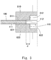
- Fig. 3 is a partial cross-sectional view of the heating electrodes brought into contact with the steel plate 100 in the heating step. More specifically, Fig. 3 is a cross-sectional view showing one side of the heating electrodes brought into contact with the steel plate 100 with respect to a central axis in a cross section including the central axis of the hole 110.
- a trim edge 112 which is an inner peripheral surface of the hole 110 is disposed so as to be positioned between the surfaces of the electrode surfaces 811 and 821 facing each other.
- the inner end surface 812 of the first heating electrode 810 and the inner end surface 822 of the second heating electrode 820 project from the trim edge 112 toward the center of the hole 110 by a length d shown in the drawing.
- the heating area 111 is heated with such an arrangement, the trim edge 112 can be sufficiently heated, and the residual strain concentrated on the peripheral part of the trim edge 112 can be satisfactorily removed. Further, since the heating area 111 is a part of the entire steel plate 100, electric power for heating unnecessary areas can be reduced, and overheating that causes softening and hardening can be avoided.
- trim edge 112 may project from the inner end surface 812 of the first heating electrode 810 and the inner end surface 822 of the second heating electrode 820 toward the center of the hole 110.
- the electrode surfaces 811 and 821 of the first heating electrode 810 and the second heating electrode 820, respectively, are annular.
- the electrode surfaces 811 and 821 may simply be circular as long as the trim edge 112 is disposed between the electrode surfaces 811 and 821.
- Fig. 4 is a partial cross-sectional view showing a relationship between heating electrodes and the steel plate 100 when other heating electrodes are used. Like Fig. 3 , Fig. 4 is a cross-sectional view showing one side of the heating electrodes and the steel plate 100 with respect to the central axis in the cross section including the central axis of the hole 110.
- the pair of heating electrodes shown in the drawing is a coil electrode that applies an alternating current to generate an induced electromotive force in the steel plate 100 to thereby heat the steel plate 100.
- the pair of heating electrodes is composed of a first heating coil 830 and a second heating coil 840.
- the first heating coil 830 is surrounded by a first support 833 that is an insulator
- the second heating coil 840 is surrounded by a second support 843 that is an insulator.
- the first support 833 and the second support 843 are brought into contact with the surfaces of the steel plate 100.
- the distance between the first heating coil 830 and the second heating coil 840 becomes stable, which makes it easy to control the temperature.
- the first heating coil 830 and the second heating coil 840 are not brought into direct contact with the surfaces of the steel plate 100, damage to the electrodes can be reduced.
- a trim edge 112 which is an inner peripheral surface of the hole 110 is disposed so as to be positioned between the electrode surfaces facing each other.
- an inner end surface 832 of the first heating coil 830 and an inner end surface 842 of the second heating coil 840 project from the trim edge 112 toward the center of the hole 110 by a length d shown in the drawing.
- first heating coil 830 and the second heating coil 840 there can be various shapes and arrangements of the first heating coil 830 and the second heating coil 840.
- the first heating coil 830 and the second heating coil 840 are provided so as to surround the hole 110 in an annular shape. By providing the heating coils in this manner, the heating area 111 including the trim edge 112 can be efficiently heated.
- Fig. 5 illustrates an FR lower arm 200 used for a vehicle suspension as a first example of the formed product.
- a bush press-fitting part 210 of the FR lower arm 200 is formed by the above-described processing method.
- Fig. 6 illustrates an A pillar lower 300 used for a window column of a vehicle as a second example of the formed product.
- the punching step of punching the steel plate 100 is not limited to punching a hole and may instead include cutting off an unnecessary part.
- a flange die is pressed against the trim edge, from which an unnecessary part has been cut off, to form a stretch flange.
- a stretch flange forming part 310 of the A pillar lower 300 is formed in this way.
- FIG. 7 is a schematic cross-sectional view showing a configuration of the first and second heating electrodes according to this embodiment.
- a first heating electrode 850 has, for example, a conical shape, and is in line contact with a corner part of the trim edge 112 of the steel plate 100.
- a second heating electrode 860 has a cylindrical shape.
- the first heating electrode 850 and the second heating electrode 860 are formed of, for example, copper.
- the trim edge 112 of the steel plate 100 is sandwiched between the first heating electrode 850 having a conical shape and the second heating electrode 860 having a cylindrical shape, and a current is applied to heat the steel plate 100.
- an electrode surface 851 of the first heating electrode 850 is brought into line contact with the corner part of the trim edge 112 of the steel plate 100
- an electrode surface 861 of the second heating electrode 860 is brought into contact with another surface side of the heating area 111 of the steel plate 100, and then a current is applied to the heating electrodes.
- the second heating electrode 860 has a cylindrical shape, but the present disclosure is not limited to this.
- the second heating electrode 860 may have, for example, a columnar shape as long as the heating area 111 of the steel plate 100 can be sandwiched between the first heating electrode 850 and the second heating electrode 860.
- the second heating electrode 860 may have a conical shape, and the first heating electrode 850 may have a cylindrical shape.
- burrs are generated at the trim edge 112 of the steel plate 100.
- a conical heating electrode may be disposed on the side of the steel plate 100 where the burrs are generated. This is because the current density of the conical heating electrode is higher, which makes it easy to crush the burrs, thereby making it easy to process the steel plate 100 in the subsequent processes.
- the first heating electrode 850 has a spherical shape, and may be in line contact with the corner part of the trim edge 112 of the steel plate 100.
- the electrode surface 851 of the first heating electrode 850 is in line contact with the corner part of the trim edge 112 of the steel plate 100.
- the punching step of punching the steel plate 100 is not limited to punching a hole.
- the punching step of punching the steel plate 100 when an unnecessary part is cut off in the punching step of punching the steel plate 100 to form the A pillar lower 300 or the like, only one of the first heating electrode 850 and the second heating electrodes 860 is configured to be in line contact with the cut off part.
- only one of the first heating electrodes 850 and the second heating electrode 860 is brought into line contact with the corner part of the trim edge 112 to increase the current density. Then, the trim edge 112 of the steel plate 100 can be heated more uniformly and efficiently, and the residual strain can be satisfactorily removed.
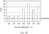
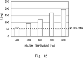
- Fig. 10 is a drawing showing a result of the test on the above-described 1180 GA steel plate 100 having a thickness of 1.2 mm.
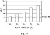
- Fig. 11 is a drawing showing a result of the test on the 980HR steel plate 100 (hot-rolled material having a tensile strength of 980 MPa) with a thickness of 2.9 mm, under the same conditions as those described above.
- the horizontal axis represents a heating temperature of the trim edge 112 of the steel plate 100
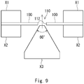
- the vertical axis represents a rate of the diameter expansion of the hole until a crack penetrates the trim edge 112 of the steel plate 100.
- db is a hole diameter when a crack penetrates, and do is an initial hole diameter before the triangular pyramid die X3 is pushed into the hole.
- Five hole expansion tests are conducted, and an average value of ⁇ in the five tests is calculated.
Landscapes
- Chemical & Material Sciences (AREA)
- Engineering & Computer Science (AREA)
- Mechanical Engineering (AREA)
- Materials Engineering (AREA)
- Thermal Sciences (AREA)
- Crystallography & Structural Chemistry (AREA)
- Physics & Mathematics (AREA)
- Metallurgy (AREA)
- Organic Chemistry (AREA)
- Health & Medical Sciences (AREA)
- Child & Adolescent Psychology (AREA)
- Shaping Metal By Deep-Drawing, Or The Like (AREA)
- Heat Treatment Of Articles (AREA)
Claims (5)
- Procédé de traitement d'une plaque d'acier (100) comprenant :le poinçonnage d'une plaque d'acier (100) ; etla disposition d'électrodes de chauffage (850, 860) de telle manière qu'un trait de coupe (112) poinçonné lors du poinçonnage est positionné entre des surfaces d'électrodes (31) se faisant face, puis le chauffage d'une partie de la plaque d'acier (100) comprenant le trait de coupe (112) par application d'un courant aux électrodes de chauffage,caractérisé en ce que, lors de la disposition, une seule des électrodes de chauffage (850) se faisant face est mise en contact linéaire avec le trait de coupe (112) et une surface d'électrode (861) d'une seconde électrode de chauffage (860) est mise en contact avec un côté de surface de la partie de la plaque d'acier (100) à chauffer.
- Procédé selon la revendication 1, comprenant en outre :la réduction de la chaleur générée lors du chauffage ; etla formation d'une bride d'étirement (113) au niveau du trait de coupe (112).
- Procédé selon la revendication 1 ou 2, dans lequel, lors du chauffage, le trait de coupe (112) est chauffé à 200 °C ou plus et à moins qu'un point Acl.
- Procédé selon la revendication 1, 2 ou 3, dans lequel l'électrode de chauffage (850) en contact linéaire avec le trait de coupe (112) a une forme conique ou une forme sphérique.
- Procédé selon la revendication 1, 2, 3 ou 4, dans lequel l'électrode de chauffage (850, 860) configurée pour être mise en contact linéaire avec le trait de coupe (112) est disposée sur un côté du trait de coupe (112) de la plaque d'acier (100) où des bavures sont générées lors du poinçonnage.
Applications Claiming Priority (2)
| Application Number | Priority Date | Filing Date | Title |
|---|---|---|---|
| JP2019011010 | 2019-01-25 | ||
| JP2019225206A JP7207283B2 (ja) | 2019-01-25 | 2019-12-13 | 鋼板の成形加工方法 |
Publications (2)
| Publication Number | Publication Date |
|---|---|
| EP3685933A1 EP3685933A1 (fr) | 2020-07-29 |
| EP3685933B1 true EP3685933B1 (fr) | 2021-09-08 |
Family
ID=69104327
Family Applications (1)
| Application Number | Title | Priority Date | Filing Date |
|---|---|---|---|
| EP20150106.1A Active EP3685933B1 (fr) | 2019-01-25 | 2020-01-02 | Procédé de traitement de plaque d'acier |
Country Status (4)
| Country | Link |
|---|---|
| US (1) | US11732317B2 (fr) |
| EP (1) | EP3685933B1 (fr) |
| CN (1) | CN111485090B (fr) |
| CA (1) | CA3069692A1 (fr) |
Families Citing this family (7)
| Publication number | Priority date | Publication date | Assignee | Title |
|---|---|---|---|---|
| JP7052743B2 (ja) | 2019-01-25 | 2022-04-12 | トヨタ自動車株式会社 | 鋼板の成形加工方法および打ち抜き加工機 |
| US11173777B2 (en) * | 2019-05-16 | 2021-11-16 | Ford Global Technologies, Llc | Battery pack mounting system and mounting method |
| CN114326187B (zh) * | 2020-09-29 | 2024-04-23 | 北京小米移动软件有限公司 | 金属背板及其制造方法、背光模组和电子设备 |
| JP2022108601A (ja) * | 2021-01-13 | 2022-07-26 | トヨタ自動車株式会社 | 成形加工方法 |
| CN114509554B (zh) * | 2022-02-08 | 2024-02-06 | 首钢集团有限公司 | 钢板冲裁质量判定方法及终端设备 |
| JP2024000181A (ja) * | 2022-06-20 | 2024-01-05 | トヨタ自動車株式会社 | 成形加工方法 |
| CN117686317B (zh) * | 2024-02-01 | 2024-04-09 | 贵州桥梁建设集团有限责任公司 | 一种线索张力测试装置及检测方法 |
Family Cites Families (24)
| Publication number | Priority date | Publication date | Assignee | Title |
|---|---|---|---|---|
| JP2783490B2 (ja) | 1993-02-02 | 1998-08-06 | 本田技研工業株式会社 | 集合ブランク部材の製造方法 |
| JP3471418B2 (ja) | 1994-05-16 | 2003-12-02 | 本田技研工業株式会社 | 残留歪の除去方法 |
| JP2894240B2 (ja) * | 1995-04-28 | 1999-05-24 | トヨタ自動車株式会社 | 鋼板の打ち抜き加工方法 |
| JPH08311694A (ja) | 1995-05-16 | 1996-11-26 | Nkk Corp | 電解クロメート処理鋼板 |
| SE516374C2 (en) | 2000-02-22 | 2002-01-08 | Workpiece controlled shaping of metal, preferably in the form of plates or bands, comprises heating the workpiece across notches or zones to reduce locally the tensile strength | |
| JP2002113525A (ja) | 2000-10-04 | 2002-04-16 | Sanwa Packing Kogyo Co Ltd | 金属製カバー、その製造方法及びそれに用いるプレス用金型 |
| JP2003145222A (ja) | 2001-11-14 | 2003-05-20 | Kobe Steel Ltd | アルミニウム合金板のプレス加工方法およびアルミニウム合金板 |
| JP2004106035A (ja) | 2002-09-19 | 2004-04-08 | Nippon Steel Corp | 金属薄板用加熱電極およびそれを用いた金属薄板加熱方法 |
| JP2007319912A (ja) * | 2006-06-02 | 2007-12-13 | Mazda Motor Corp | 穴開け装置および該装置を用いた穴開け方法 |
| DE102008014559A1 (de) * | 2008-03-15 | 2009-09-17 | Elringklinger Ag | Verfahren zum bereichsweisen Umformen einer aus einem Federstahlblech hergestellten Blechlage einer Flachdichtung sowie Einrichtung zur Durchführung dieses Verfahrens |
| JP2009255158A (ja) | 2008-04-21 | 2009-11-05 | Aisin Seiki Co Ltd | 金属材のバーリング加工方法 |
| US9145594B2 (en) * | 2010-03-24 | 2015-09-29 | Jfe Steel Corporation | Method for manufacturing ultra high strength member |
| JP5299403B2 (ja) | 2010-11-09 | 2013-09-25 | 株式会社デンソー | 孔加工装置および孔加工方法 |
| JP2012206539A (ja) | 2011-03-29 | 2012-10-25 | Aisin Takaoka Ltd | 部分加熱成形体の製造方法 |
| DE102013012684A1 (de) | 2013-07-31 | 2015-02-05 | Allgaier Werke Gmbh | Vorrichtung zum Umformen von Metallen |
| DE102014016614A1 (de) * | 2014-10-31 | 2016-05-04 | Salzgitter Flachstahl Gmbh | Verfahren zur Herstellung eines Bauteils durch Umformen einer Platine aus Stahl |
| CA2977205C (fr) * | 2015-03-11 | 2020-01-07 | Nippon Steel & Sumitomo Metal Corporation | Procede de bordage |
| MX2018008915A (es) | 2016-01-21 | 2018-09-11 | Nippon Steel & Sumitomo Metal Corp | Metodo para el procesamiento de desbarbado y dispositivo para el procesamiento de desbarbado. |
| DE102016101975B4 (de) | 2016-02-04 | 2017-10-19 | Voestalpine Metal Forming Gmbh | Vorrichtung zum Herstellen von gehärteten Stahlbauteilen und Verfahren zum Härten |
| JP2017161046A (ja) | 2016-03-11 | 2017-09-14 | Ntn株式会社 | 軌道輪の製造方法 |
| CN106734506B (zh) * | 2016-12-09 | 2018-10-09 | 山东科技大学 | 基于直接感应加热的齿板局部热冲裁系统及工艺 |
| JP6978263B2 (ja) | 2017-09-25 | 2021-12-08 | 東プレ株式会社 | ホットプレス製品の製造方法 |
| JP7129807B2 (ja) | 2018-03-30 | 2022-09-02 | 大阪瓦斯株式会社 | パンチ孔形成方法及びパンチ孔形成装置 |
| JP7052743B2 (ja) | 2019-01-25 | 2022-04-12 | トヨタ自動車株式会社 | 鋼板の成形加工方法および打ち抜き加工機 |
-
2020
- 2020-01-02 EP EP20150106.1A patent/EP3685933B1/fr active Active
- 2020-01-22 CN CN202010073914.6A patent/CN111485090B/zh active Active
- 2020-01-23 US US16/750,373 patent/US11732317B2/en active Active
- 2020-01-24 CA CA3069692A patent/CA3069692A1/en not_active Abandoned
Also Published As
| Publication number | Publication date |
|---|---|
| CA3069692A1 (en) | 2020-07-25 |
| CN111485090A (zh) | 2020-08-04 |
| CN111485090B (zh) | 2022-06-10 |
| US11732317B2 (en) | 2023-08-22 |
| EP3685933A1 (fr) | 2020-07-29 |
| US20200239974A1 (en) | 2020-07-30 |
Similar Documents
| Publication | Publication Date | Title |
|---|---|---|
| EP3685933B1 (fr) | Procédé de traitement de plaque d'acier | |
| JP5740099B2 (ja) | 熱間プレス製品の製造方法 | |
| US11383288B2 (en) | Method of processing steel plate and punching machine | |
| RU2678849C1 (ru) | Способ отбортовки отверстия | |
| CN111565863A (zh) | 冲压成型品的制造方法 | |
| KR102000859B1 (ko) | 전단 가공 방법 | |
| US5911844A (en) | Method for forming a metallic material | |
| JP7207283B2 (ja) | 鋼板の成形加工方法 | |
| JP2006224121A (ja) | 鋼板打ち抜き用工具及びそれを用いた打ち抜き方法 | |
| CN113365752A (zh) | 冲压部件的制造方法以及坯料的制造方法 | |
| JP2009255167A (ja) | 面取りダイを用いた打ち抜き加工方法及び装置 | |
| JP7188457B2 (ja) | 金属板のせん断加工方法及びプレス部品の製造方法 | |
| JP2004174542A (ja) | 金属板材のプレス加工方法 | |
| KR20120127974A (ko) | 관형 금속재료의 결정립 미세화 방법 | |
| US20230113628A1 (en) | Method for manufacturing pressed component, method for manufacturing blank material, and steel sheet | |
| WO2022004296A1 (fr) | Procédé de cisaillement de feuille métallique, procédé de fabrication de composant pressé, feuille métallique et matrice de cisaillement pour feuille métallique | |
| JP7318602B2 (ja) | 試験体の作製方法、及び高張力鋼板の遅れ破壊特性評価方法 | |
| CN114762874A (zh) | 成形加工方法 | |
| JP2019111567A (ja) | プレス成形品の製造方法 | |
| JP2002346653A (ja) | 順送りプレス加工方法 | |
| CN106064193A (zh) | 一种超高强钢板的冲裁方法 | |
| JP6729174B2 (ja) | 剪断加工方法 | |
| CN117897239A (zh) | 金属板的延迟破坏特性改善方法、坯料的制造方法、冲压成形品的制造方法和冲压成形品 | |
| JPH10251747A (ja) | 疲労強度に優れた鋼板部材 | |
| JP2000343145A (ja) | ロータリーブランキング用ロール金型およびロータリーブランキング方法 |
Legal Events
| Date | Code | Title | Description |
|---|---|---|---|
| PUAI | Public reference made under article 153(3) epc to a published international application that has entered the european phase |
Free format text: ORIGINAL CODE: 0009012 |
|
| STAA | Information on the status of an ep patent application or granted ep patent |
Free format text: STATUS: REQUEST FOR EXAMINATION WAS MADE |
|
| 17P | Request for examination filed |
Effective date: 20200102 |
|
| AK | Designated contracting states |
Kind code of ref document: A1 Designated state(s): AL AT BE BG CH CY CZ DE DK EE ES FI FR GB GR HR HU IE IS IT LI LT LU LV MC MK MT NL NO PL PT RO RS SE SI SK SM TR |
|
| AX | Request for extension of the european patent |
Extension state: BA ME |
|
| GRAP | Despatch of communication of intention to grant a patent |
Free format text: ORIGINAL CODE: EPIDOSNIGR1 |
|
| STAA | Information on the status of an ep patent application or granted ep patent |
Free format text: STATUS: GRANT OF PATENT IS INTENDED |
|
| RIC1 | Information provided on ipc code assigned before grant |
Ipc: B21D 19/08 20060101ALI20210210BHEP Ipc: C21D 1/30 20060101ALI20210210BHEP Ipc: B21D 19/00 20060101AFI20210210BHEP Ipc: B21D 28/02 20060101ALI20210210BHEP Ipc: C21D 9/48 20060101ALI20210210BHEP Ipc: C21D 1/42 20060101ALI20210210BHEP Ipc: C21D 1/40 20060101ALI20210210BHEP Ipc: B21D 37/16 20060101ALI20210210BHEP Ipc: B21D 28/26 20060101ALI20210210BHEP |
|
| INTG | Intention to grant announced |
Effective date: 20210317 |
|
| GRAJ | Information related to disapproval of communication of intention to grant by the applicant or resumption of examination proceedings by the epo deleted |
Free format text: ORIGINAL CODE: EPIDOSDIGR1 |
|
| STAA | Information on the status of an ep patent application or granted ep patent |
Free format text: STATUS: REQUEST FOR EXAMINATION WAS MADE |
|
| GRAP | Despatch of communication of intention to grant a patent |
Free format text: ORIGINAL CODE: EPIDOSNIGR1 |
|
| INTC | Intention to grant announced (deleted) | ||
| STAA | Information on the status of an ep patent application or granted ep patent |
Free format text: STATUS: GRANT OF PATENT IS INTENDED |
|
| INTG | Intention to grant announced |
Effective date: 20210610 |
|
| GRAS | Grant fee paid |
Free format text: ORIGINAL CODE: EPIDOSNIGR3 |
|
| GRAA | (expected) grant |
Free format text: ORIGINAL CODE: 0009210 |
|
| STAA | Information on the status of an ep patent application or granted ep patent |
Free format text: STATUS: THE PATENT HAS BEEN GRANTED |
|
| AK | Designated contracting states |
Kind code of ref document: B1 Designated state(s): AL AT BE BG CH CY CZ DE DK EE ES FI FR GB GR HR HU IE IS IT LI LT LU LV MC MK MT NL NO PL PT RO RS SE SI SK SM TR |
|
| REG | Reference to a national code |
Ref country code: GB Ref legal event code: FG4D |
|
| REG | Reference to a national code |
Ref country code: CH Ref legal event code: EP Ref country code: AT Ref legal event code: REF Ref document number: 1428118 Country of ref document: AT Kind code of ref document: T Effective date: 20210915 |
|
| REG | Reference to a national code |
Ref country code: DE Ref legal event code: R096 Ref document number: 602020000479 Country of ref document: DE |
|
| REG | Reference to a national code |
Ref country code: IE Ref legal event code: FG4D |
|
| REG | Reference to a national code |
Ref country code: LT Ref legal event code: MG9D |
|
| REG | Reference to a national code |
Ref country code: NL Ref legal event code: MP Effective date: 20210908 |
|
| PG25 | Lapsed in a contracting state [announced via postgrant information from national office to epo] |
Ref country code: RS Free format text: LAPSE BECAUSE OF FAILURE TO SUBMIT A TRANSLATION OF THE DESCRIPTION OR TO PAY THE FEE WITHIN THE PRESCRIBED TIME-LIMIT Effective date: 20210908 Ref country code: SE Free format text: LAPSE BECAUSE OF FAILURE TO SUBMIT A TRANSLATION OF THE DESCRIPTION OR TO PAY THE FEE WITHIN THE PRESCRIBED TIME-LIMIT Effective date: 20210908 Ref country code: ES Free format text: LAPSE BECAUSE OF FAILURE TO SUBMIT A TRANSLATION OF THE DESCRIPTION OR TO PAY THE FEE WITHIN THE PRESCRIBED TIME-LIMIT Effective date: 20210908 Ref country code: HR Free format text: LAPSE BECAUSE OF FAILURE TO SUBMIT A TRANSLATION OF THE DESCRIPTION OR TO PAY THE FEE WITHIN THE PRESCRIBED TIME-LIMIT Effective date: 20210908 Ref country code: FI Free format text: LAPSE BECAUSE OF FAILURE TO SUBMIT A TRANSLATION OF THE DESCRIPTION OR TO PAY THE FEE WITHIN THE PRESCRIBED TIME-LIMIT Effective date: 20210908 Ref country code: NO Free format text: LAPSE BECAUSE OF FAILURE TO SUBMIT A TRANSLATION OF THE DESCRIPTION OR TO PAY THE FEE WITHIN THE PRESCRIBED TIME-LIMIT Effective date: 20211208 Ref country code: LT Free format text: LAPSE BECAUSE OF FAILURE TO SUBMIT A TRANSLATION OF THE DESCRIPTION OR TO PAY THE FEE WITHIN THE PRESCRIBED TIME-LIMIT Effective date: 20210908 Ref country code: BG Free format text: LAPSE BECAUSE OF FAILURE TO SUBMIT A TRANSLATION OF THE DESCRIPTION OR TO PAY THE FEE WITHIN THE PRESCRIBED TIME-LIMIT Effective date: 20211208 |
|
| REG | Reference to a national code |
Ref country code: AT Ref legal event code: MK05 Ref document number: 1428118 Country of ref document: AT Kind code of ref document: T Effective date: 20210908 |
|
| PG25 | Lapsed in a contracting state [announced via postgrant information from national office to epo] |
Ref country code: LV Free format text: LAPSE BECAUSE OF FAILURE TO SUBMIT A TRANSLATION OF THE DESCRIPTION OR TO PAY THE FEE WITHIN THE PRESCRIBED TIME-LIMIT Effective date: 20210908 Ref country code: GR Free format text: LAPSE BECAUSE OF FAILURE TO SUBMIT A TRANSLATION OF THE DESCRIPTION OR TO PAY THE FEE WITHIN THE PRESCRIBED TIME-LIMIT Effective date: 20211209 |
|
| PG25 | Lapsed in a contracting state [announced via postgrant information from national office to epo] |
Ref country code: AT Free format text: LAPSE BECAUSE OF FAILURE TO SUBMIT A TRANSLATION OF THE DESCRIPTION OR TO PAY THE FEE WITHIN THE PRESCRIBED TIME-LIMIT Effective date: 20210908 |
|
| PG25 | Lapsed in a contracting state [announced via postgrant information from national office to epo] |
Ref country code: IS Free format text: LAPSE BECAUSE OF FAILURE TO SUBMIT A TRANSLATION OF THE DESCRIPTION OR TO PAY THE FEE WITHIN THE PRESCRIBED TIME-LIMIT Effective date: 20220108 Ref country code: SM Free format text: LAPSE BECAUSE OF FAILURE TO SUBMIT A TRANSLATION OF THE DESCRIPTION OR TO PAY THE FEE WITHIN THE PRESCRIBED TIME-LIMIT Effective date: 20210908 Ref country code: SK Free format text: LAPSE BECAUSE OF FAILURE TO SUBMIT A TRANSLATION OF THE DESCRIPTION OR TO PAY THE FEE WITHIN THE PRESCRIBED TIME-LIMIT Effective date: 20210908 Ref country code: RO Free format text: LAPSE BECAUSE OF FAILURE TO SUBMIT A TRANSLATION OF THE DESCRIPTION OR TO PAY THE FEE WITHIN THE PRESCRIBED TIME-LIMIT Effective date: 20210908 Ref country code: PT Free format text: LAPSE BECAUSE OF FAILURE TO SUBMIT A TRANSLATION OF THE DESCRIPTION OR TO PAY THE FEE WITHIN THE PRESCRIBED TIME-LIMIT Effective date: 20220110 Ref country code: PL Free format text: LAPSE BECAUSE OF FAILURE TO SUBMIT A TRANSLATION OF THE DESCRIPTION OR TO PAY THE FEE WITHIN THE PRESCRIBED TIME-LIMIT Effective date: 20210908 Ref country code: NL Free format text: LAPSE BECAUSE OF FAILURE TO SUBMIT A TRANSLATION OF THE DESCRIPTION OR TO PAY THE FEE WITHIN THE PRESCRIBED TIME-LIMIT Effective date: 20210908 Ref country code: EE Free format text: LAPSE BECAUSE OF FAILURE TO SUBMIT A TRANSLATION OF THE DESCRIPTION OR TO PAY THE FEE WITHIN THE PRESCRIBED TIME-LIMIT Effective date: 20210908 Ref country code: CZ Free format text: LAPSE BECAUSE OF FAILURE TO SUBMIT A TRANSLATION OF THE DESCRIPTION OR TO PAY THE FEE WITHIN THE PRESCRIBED TIME-LIMIT Effective date: 20210908 Ref country code: AL Free format text: LAPSE BECAUSE OF FAILURE TO SUBMIT A TRANSLATION OF THE DESCRIPTION OR TO PAY THE FEE WITHIN THE PRESCRIBED TIME-LIMIT Effective date: 20210908 |
|
| REG | Reference to a national code |
Ref country code: DE Ref legal event code: R097 Ref document number: 602020000479 Country of ref document: DE |
|
| PLBE | No opposition filed within time limit |
Free format text: ORIGINAL CODE: 0009261 |
|
| STAA | Information on the status of an ep patent application or granted ep patent |
Free format text: STATUS: NO OPPOSITION FILED WITHIN TIME LIMIT |
|
| PG25 | Lapsed in a contracting state [announced via postgrant information from national office to epo] |
Ref country code: DK Free format text: LAPSE BECAUSE OF FAILURE TO SUBMIT A TRANSLATION OF THE DESCRIPTION OR TO PAY THE FEE WITHIN THE PRESCRIBED TIME-LIMIT Effective date: 20210908 |
|
| 26N | No opposition filed |
Effective date: 20220609 |
|
| PG25 | Lapsed in a contracting state [announced via postgrant information from national office to epo] |
Ref country code: SI Free format text: LAPSE BECAUSE OF FAILURE TO SUBMIT A TRANSLATION OF THE DESCRIPTION OR TO PAY THE FEE WITHIN THE PRESCRIBED TIME-LIMIT Effective date: 20210908 Ref country code: MC Free format text: LAPSE BECAUSE OF FAILURE TO SUBMIT A TRANSLATION OF THE DESCRIPTION OR TO PAY THE FEE WITHIN THE PRESCRIBED TIME-LIMIT Effective date: 20210908 |
|
| REG | Reference to a national code |
Ref country code: BE Ref legal event code: MM Effective date: 20220131 |
|
| PG25 | Lapsed in a contracting state [announced via postgrant information from national office to epo] |
Ref country code: LU Free format text: LAPSE BECAUSE OF NON-PAYMENT OF DUE FEES Effective date: 20220102 |
|
| PG25 | Lapsed in a contracting state [announced via postgrant information from national office to epo] |
Ref country code: BE Free format text: LAPSE BECAUSE OF NON-PAYMENT OF DUE FEES Effective date: 20220131 |
|
| PG25 | Lapsed in a contracting state [announced via postgrant information from national office to epo] |
Ref country code: IT Free format text: LAPSE BECAUSE OF FAILURE TO SUBMIT A TRANSLATION OF THE DESCRIPTION OR TO PAY THE FEE WITHIN THE PRESCRIBED TIME-LIMIT Effective date: 20210908 Ref country code: IE Free format text: LAPSE BECAUSE OF NON-PAYMENT OF DUE FEES Effective date: 20220102 |
|
| PGFP | Annual fee paid to national office [announced via postgrant information from national office to epo] |
Ref country code: FR Payment date: 20221208 Year of fee payment: 4 |
|
| PGFP | Annual fee paid to national office [announced via postgrant information from national office to epo] |
Ref country code: DE Payment date: 20221130 Year of fee payment: 4 |
|
| P01 | Opt-out of the competence of the unified patent court (upc) registered |
Effective date: 20230427 |
|
| REG | Reference to a national code |
Ref country code: DE Ref legal event code: R084 Ref document number: 602020000479 Country of ref document: DE |
|
| REG | Reference to a national code |
Ref country code: CH Ref legal event code: PL |
|
| REG | Reference to a national code |
Ref country code: GB Ref legal event code: 746 Effective date: 20230816 |
|
| PG25 | Lapsed in a contracting state [announced via postgrant information from national office to epo] |
Ref country code: LI Free format text: LAPSE BECAUSE OF NON-PAYMENT OF DUE FEES Effective date: 20230131 Ref country code: CH Free format text: LAPSE BECAUSE OF NON-PAYMENT OF DUE FEES Effective date: 20230131 |
|
| PG25 | Lapsed in a contracting state [announced via postgrant information from national office to epo] |
Ref country code: MK Free format text: LAPSE BECAUSE OF FAILURE TO SUBMIT A TRANSLATION OF THE DESCRIPTION OR TO PAY THE FEE WITHIN THE PRESCRIBED TIME-LIMIT Effective date: 20210908 Ref country code: CY Free format text: LAPSE BECAUSE OF FAILURE TO SUBMIT A TRANSLATION OF THE DESCRIPTION OR TO PAY THE FEE WITHIN THE PRESCRIBED TIME-LIMIT Effective date: 20210908 |