EP3684233B1 - Vorrichtung zum aufbereiten von lebensmitteln mit dampf - Google Patents
Vorrichtung zum aufbereiten von lebensmitteln mit dampf Download PDFInfo
- Publication number
- EP3684233B1 EP3684233B1 EP18822270.7A EP18822270A EP3684233B1 EP 3684233 B1 EP3684233 B1 EP 3684233B1 EP 18822270 A EP18822270 A EP 18822270A EP 3684233 B1 EP3684233 B1 EP 3684233B1
- Authority
- EP
- European Patent Office
- Prior art keywords
- rinsing
- steam
- opening
- rinsing tank
- mounting plate
- Prior art date
- Legal status (The legal status is an assumption and is not a legal conclusion. Google has not performed a legal analysis and makes no representation as to the accuracy of the status listed.)
- Active
Links
Images

Classifications
-
- A—HUMAN NECESSITIES
- A47—FURNITURE; DOMESTIC ARTICLES OR APPLIANCES; COFFEE MILLS; SPICE MILLS; SUCTION CLEANERS IN GENERAL
- A47J—KITCHEN EQUIPMENT; COFFEE MILLS; SPICE MILLS; APPARATUS FOR MAKING BEVERAGES
- A47J27/00—Cooking-vessels
- A47J27/04—Cooking-vessels for cooking food in steam; Devices for extracting fruit juice by means of steam ; Vacuum cooking vessels
-
- A—HUMAN NECESSITIES
- A47—FURNITURE; DOMESTIC ARTICLES OR APPLIANCES; COFFEE MILLS; SPICE MILLS; SUCTION CLEANERS IN GENERAL
- A47J—KITCHEN EQUIPMENT; COFFEE MILLS; SPICE MILLS; APPARATUS FOR MAKING BEVERAGES
- A47J27/00—Cooking-vessels
- A47J27/14—Cooking-vessels for use in hotels, restaurants, or canteens
- A47J27/16—Cooking-vessels for use in hotels, restaurants, or canteens heated by steam
-
- B—PERFORMING OPERATIONS; TRANSPORTING
- B08—CLEANING
- B08B—CLEANING IN GENERAL; PREVENTION OF FOULING IN GENERAL
- B08B3/00—Cleaning by methods involving the use or presence of liquid or steam
- B08B3/02—Cleaning by the force of jets or sprays
-
- F—MECHANICAL ENGINEERING; LIGHTING; HEATING; WEAPONS; BLASTING
- F16—ENGINEERING ELEMENTS AND UNITS; GENERAL MEASURES FOR PRODUCING AND MAINTAINING EFFECTIVE FUNCTIONING OF MACHINES OR INSTALLATIONS; THERMAL INSULATION IN GENERAL
- F16L—PIPES; JOINTS OR FITTINGS FOR PIPES; SUPPORTS FOR PIPES, CABLES OR PROTECTIVE TUBING; MEANS FOR THERMAL INSULATION IN GENERAL
- F16L21/00—Joints with sleeve or socket
- F16L21/002—Sleeves or nipples for pipes of the same diameter; Reduction pieces
- F16L21/005—Sleeves or nipples for pipes of the same diameter; Reduction pieces made of elastic material, e.g. partly or completely surrounded by clamping devices
-
- F—MECHANICAL ENGINEERING; LIGHTING; HEATING; WEAPONS; BLASTING
- F24—HEATING; RANGES; VENTILATING
- F24C—DOMESTIC STOVES OR RANGES ; DETAILS OF DOMESTIC STOVES OR RANGES, OF GENERAL APPLICATION
- F24C15/00—Details
- F24C15/003—Details moisturising of air
-
- A—HUMAN NECESSITIES
- A47—FURNITURE; DOMESTIC ARTICLES OR APPLIANCES; COFFEE MILLS; SPICE MILLS; SUCTION CLEANERS IN GENERAL
- A47J—KITCHEN EQUIPMENT; COFFEE MILLS; SPICE MILLS; APPARATUS FOR MAKING BEVERAGES
- A47J27/00—Cooking-vessels
- A47J27/04—Cooking-vessels for cooking food in steam; Devices for extracting fruit juice by means of steam ; Vacuum cooking vessels
- A47J2027/043—Cooking-vessels for cooking food in steam; Devices for extracting fruit juice by means of steam ; Vacuum cooking vessels for cooking food in steam
Definitions
- the invention relates to a device according to the preamble of claim 1 for processing food received in a vessel, in particular ready meals, (with steam) comprising a steam generating unit for generating steam, a steam supply unit connected to the steam generating unit via a steam supply line and having at least one steam discharge opening having steam probe and drive means for, translational, adjustment of the steam supply unit relative to a, preferably arranged along the vertical line below the steam supply unit, having a rinsing tub having rinsing device with means for rinsing water, in particular comprising a spray nozzle for rinsing, in particular spraying, the steam probe after a food preparation process (with rinsing water) , wherein the rinsing tub is connected in a fluid-conducting manner to a drain section for discharging contaminated rinsing water.
- a steam supply unit which is supplied with steam by a steam generating unit, is translationally adjustable in the vertical direction relative to a rinsing device.
- the flushing device comprises a permanently piped flushing tub which is mounted from above on a work surface.
- the invention is based on the object of specifying a device that is easier to clean for preparing foodstuffs accommodated in a vessel.
- the device or its flushing device should also be able to be installed easily or without great effort.
- a device with the features of claim 1 that is, in a generic device in that a washing tub has a drainage funnel with the drainage line section, which is detachable from the washing tub with sealing means for cleaning and / or replacement purposes, in particular without tools is fixed.
- the drainage line section can be designed in one piece, in particular monolithically, with the drainage funnel or as a component that is separate from it and fixed to it.
- the invention is based on the idea of providing a drainage funnel in the area of the sink base, via which soiled washing water can flow through a drainage opening of the drainage funnel to the drainage line section, which is formed integrally with the drainage funnel or is preferably fixed on the outlet side of this drainage funnel.
- the drainage funnel is detachably fixed on or in the washing tub in order to remove it from the washing tub for cleaning and / or replacement purposes of the drainage funnel and / or the drainage line section, in particular without tools to be able to dismantle.
- the detachable connection is provided on the washing tub and / or the drainage funnel, which, as will be explained later, is preferably at the same time the fixing function for realizing the detachable Have a connection between the rinsing tub and the drainage funnel. If the drain or drain line section becomes clogged in practice, the drain funnel together with the drain line section formed or attached to it can easily be detached from the washing tub and cleaned without tools. In this way, the drain funnel and / or drain line section can be exchanged in a simple manner in the event of wear.
- the drainage line section has a free end which, for example, opens into a siphon or a collecting container, in particular is loosely suspended there or protrudes in order to prevent the drainage funnel and drainage line section from being removed not from a counterpart, in particular a pipe socket or the like. Having to disconnect the drain line connection.
- the drainage funnel forms the drain of the washing tub and is preferably detachably inserted into a bottom or bottom mounting opening of the washing tub, in particular from above, ie from the direction of an upper washing tub opening.
- the sealing means for sealing the releasable connection between the drainage funnel and the rinsing tub are designed as, in particular, the sole fixing means for holding the drainage funnel, in particular form-fitting and / or clamping and / or latching.
- the sealing means are provided to form a detachable, fixed (and of course tight) connection between the washing basin and the drainage funnel.
- the sealing means are fixed at least in sections to the washing tub and / or the drainage funnel, in particular through a one-piece design, for example in the multi-component injection molding process.
- a form-fitting connection can be implemented, for example, in that the sealing means form a circumferential groove in the area of the assembly opening in the sink and / or opposite on the drainage funnel, in which a corresponding circumferential bead of the radially opposite part engages in a form-fitting manner, in particular with a latching and / or clamping mechanism, or vice versa .
- the rinsing tub is designed as a multicomponent plastic part, very particularly preferably as a multicomponent injection-molded part.
- the multicomponent rinsing tub comprises an elastomeric material that at least partially forms the sealant and a plastic material that is rigid compared to the elastomeric material and that, in particular, forms the tub shape and / or a preferably provided mounting plate section shape to be explained later.
- the elastomeric material firmly formed on the rinsing tub as part of a multi-component injection molding process can also form further functional sections of the rinsing tub that will be explained later and thus, for example, limit a residual steam discharge opening or form a seal against a work surface.
- the releasable connection between the drainage funnel and the rinsing tub is designed in such a way that the drainage funnel is moved in the direction of the one above it by applying a releasing force Steam supply unit, that is, can be dismantled from the rinsing tub along the vertical upwards.
- the drainage funnel is preferably inserted in a lower assembly opening or in the area of the washing tub bottom in such a way that the funnel can be removed from the assembly opening, preferably by a force in the direction of an upper washing tub opening, preferably as part of a purely translational movement while overcoming a corresponding holding force, preferably implemented by the sealing means.
- fixing or loosening can also be achieved by a rotary movement, for example by realizing a threaded connection - however, loosening by applying a tensile and / or compressive force in the vertical direction is preferred.
- the assembly is then preferably possible simply by applying a fixing force opposing the aforementioned linear release force, the drainage funnel preferably being pressed axially against a stop or abutment on the washing tub.
- the drainage line section is not rigid, but rather as a flexible drainage hose, preferably detachably secured to the drainage funnel.
- hose material For example, it is conceivable to design the hose as a plastic hose, in particular a corrugated pipe hose, or as an extruded, essentially smooth hose, in particular with an internal fabric to increase strength.
- a robust design of the drainage hose as a metal fabric hose or a metal corrugated pipe hose is very particularly preferred.
- the drainage line section in particular the drainage hose, with a free end facing away from the drainage funnel, is loosely inserted into a siphon opening is introduced and / or loosely in a collecting container, in particular a collecting container of the device, which is very particularly preferably arranged in an area below a work surface to be explained later in order to enable the drainage line section, in particular the drainage hose, to be removed, in particular without tools, together with the To enable drain funnel without first having to dismantle the drain line section from a counterpart, for example a pipe socket or clamp.
- a counterpart for example a pipe socket or clamp.
- a fixed, tight mounting of the drainage line section on a counterpart, in particular on a drainage pipe and / or siphon is also possible.
- the washing tub is surrounded by a plate-shaped or flat mounting plate section, which is very particularly preferably one-piece (monolithic) with the washing tub, in particular using the injection molding process.
- the mounting plate section can be formed by a separate mounting plate, preferably made of plastic, which is preferably connected to the washing tub, in particular a washing tub rim, for example by screwing.
- this mounting plate section is arranged below a worktop or if the worktop rests on the mounting plate section and the washing tub is accessible through a worktop opening, ie from above from the vertical direction.
- the rinsing tub can pass through the worktop opening with an upper peripheral edge and / or terminate flush with an upper work surface of the worktop opening. A complete arrangement of the rinsing tub below the top of the worktop is also conceivable.
- the mounting plate section and / or the washing tub are / is sealed with an elastomer seal. It is particularly expedient if it is an integral elastomer seal of the mounting plate section and / or the rinsing pan, which is preferably implemented in the multi-component injection molding process together with the mounting plate section and / or the rinsing pan.
- An embodiment of the device is particularly expedient in which a support section, preferably made of plastic, is formed on the mounting plate section for the steam supply unit, preferably radially spaced from an upper washing tub opening and / or formed from the mounting plate section itself (or alternatively fixed on it). on which it rests in a lower flushing position.
- the support section is preferably assigned a corresponding opening in the worktop, which opening is preferably at a distance from the worktop opening assigned to the washing tub.
- the support section preferably passes through this opening in the vertical direction upwards.
- an opening preferably radially spaced from an upper washing tub opening and / or delimited by, preferably integral, very particularly preferably implemented or injected elastomer material in the context of a multi-component injection molding process, is formed in the mounting plate section , in which a residual steam discharge line is included.
- Such an embodiment can also preferably be implemented in Multi-component injection molding processes realize and increase the functionality of the assembly, including the mounting plate section and the rinsing tub.
- a rinsing nozzle assembly opening is formed in the rinsing tub, in which a rinsing nozzle is arranged for applying a rinsing water spray jet to the steam probe.
- a flushing device 2 with flushing tub 3 is shown, which is accessible through a worktop opening 4 in the vertical direction from above.
- the worktop opening 4 is located in a worktop 5, here exemplarily made of stainless steel, with a horizontal orientation.
- a steam generation unit of the device for generating steam as well as a steam supply unit connected to it in a steam-conducting manner via a steam supply line, which, for example, as in FIG DE 10 2015 221 005 A1 described and in the figures there, in particular Fig. 1 may be formed shown.
- the steam supply unit is translationally adjustable along a vertical axis with appropriate drive means relative to a vessel with food received therein, which is located for preparing or heating the food in an area above the in Fig. 1 rinsing tub 3 shown is located, in particular carried by a horizontally adjustable carrier slide.
- the steam supply unit preferably comprises a hood for tight fit on the vessel to define a steam space.
- the steam is introduced into the food with a steam probe, such as the one in the DE 10 2015 221 005 A1 is shown - the steam probe is preferably designed and arranged or driven for the simultaneous steaming and mixing of the food, in order to bring about a better heat energy distribution.
- Rinse water application means are not shown, in particular comprising a rinsing nozzle which is inserted into an in Fig. 2
- the rinsing nozzle opening 6 shown can be inserted or mounted in the rinsing tub 3.
- the steam generating unit can be adjusted downwards along the vertical, in particular until the steam probe protrudes into the rinsing tub 3 shown, the rinsing tub 3 being closed by the aforementioned hood of the steam supply unit.
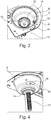
- the steam supply unit In the (lower) rinsing position described above, the steam supply unit is supported on a support section 7, which is monolithic with the rinsing tub 3 and, for this purpose, on an in Fig. 3 Mounting plate section 8 shown is formed, which in turn is formed in one piece with the washing tub 3.
- the mounting plate section 8 (and thus the support section 7) is a component that is separate from the washing tub 3 and is attached to it.
- the aforementioned mounting plate section 8 (regardless of whether it is formed in one piece or separately from the washing tub 3) is arranged below the worktop 5 - that is, the worktop 5 rests on the mounting plate section 8 in the assembled state.
- the combination of mounting plate section 8 and washing tub 3 is sealed against the worktop 5, more precisely against an underside of the worktop 5 with the aid of an annular elastomer seal 9, which was injected onto the mounting plate section 8 and / or the washing tub 3, for example, using the two-component injection molding process.
- a drain funnel 10 is located on the base or bottom of the washing tub 3, which is sealed off from the washing tub 3 by means of sealing means 11.
- the drainage funnel 10 has a central drainage opening 12, which leads to a drainage line section 13 embodied as a corrugated pipe hose, which, in the present case by way of example, by means of a fixing clamp 14 is fixed to the drainage funnel 10, more precisely a drainage extension of the drainage funnel 10.
- the flexible drainage hose or drainage line section 13 can be dismantled from the washing tub 3 together with the drainage funnel 10 without tools - for this purpose, only a release force oriented in the vertical direction towards an upper washing tub opening 15 has to be applied to the drainage funnel 10.
- the discharge funnel 10 is in the form of FIG Fig. 3
- the fixing position shown is held by the sealing means 11.
- These are formed in one piece in the two-component injection molding process with the rinsing tub 3 and have an annular groove in which a corresponding circumferential bead of the drainage funnel 10 is received.
- Fig. 2 the discharge funnel 10 is shown with the discharge line section 13 designed as a flexible hose in the dismantled state.
- the support section 7 is formed on the mounting plate section 8. This passes through an opening 16 assigned to it in the worktop 5, with a radial distance from the wash basin 3 , and which is preferably formed in one piece with the mounting plate section 8 using the two-component plastic injection molding process.
- the rinsing nozzle opening 6 is located in the rinsing tub 3 (cf. Fig. 2 ), in the representation according to Fig. 3 a rinsing nozzle 18 of the rinsing water application means is mounted.
- the opening 19 is assigned a corresponding or aligned opening in the worktop 5.
Landscapes
- Engineering & Computer Science (AREA)
- Food Science & Technology (AREA)
- General Engineering & Computer Science (AREA)
- Mechanical Engineering (AREA)
- Chemical & Material Sciences (AREA)
- Combustion & Propulsion (AREA)
- Cleaning By Liquid Or Steam (AREA)
- Cookers (AREA)
- Food-Manufacturing Devices (AREA)
- Washing And Drying Of Tableware (AREA)
Priority Applications (1)
| Application Number | Priority Date | Filing Date | Title |
|---|---|---|---|
| PL18822270T PL3684233T3 (pl) | 2017-12-04 | 2018-11-26 | Urządzenie do przygotowania środków spożywczych za pomocą pary |
Applications Claiming Priority (2)
| Application Number | Priority Date | Filing Date | Title |
|---|---|---|---|
| DE102017128767.1A DE102017128767A1 (de) | 2017-12-04 | 2017-12-04 | Vorrichtung zum Aufbereiten von Lebensmitteln mit Dampf |
| PCT/EP2018/082485 WO2019110340A1 (de) | 2017-12-04 | 2018-11-26 | Vorrichtung zum aufbereiten von lebensmitteln mit dampf |
Publications (2)
| Publication Number | Publication Date |
|---|---|
| EP3684233A1 EP3684233A1 (de) | 2020-07-29 |
| EP3684233B1 true EP3684233B1 (de) | 2021-11-03 |
Family
ID=64746512
Family Applications (1)
| Application Number | Title | Priority Date | Filing Date |
|---|---|---|---|
| EP18822270.7A Active EP3684233B1 (de) | 2017-12-04 | 2018-11-26 | Vorrichtung zum aufbereiten von lebensmitteln mit dampf |
Country Status (11)
| Country | Link |
|---|---|
| US (1) | US12108903B2 (pl) |
| EP (1) | EP3684233B1 (pl) |
| JP (1) | JP7153948B2 (pl) |
| CN (1) | CN111432690B (pl) |
| CA (1) | CA3082949A1 (pl) |
| DE (1) | DE102017128767A1 (pl) |
| DK (1) | DK3684233T3 (pl) |
| ES (1) | ES2904873T3 (pl) |
| PL (1) | PL3684233T3 (pl) |
| RU (1) | RU2768775C2 (pl) |
| WO (1) | WO2019110340A1 (pl) |
Families Citing this family (5)
| Publication number | Priority date | Publication date | Assignee | Title |
|---|---|---|---|---|
| DE202018006410U1 (de) | 2017-08-09 | 2020-04-23 | Sharkninja Operating Llc | Kochgerät und Komponenten davon |
| WO2020176477A1 (en) | 2019-02-25 | 2020-09-03 | Sharkninja Operating Llc | Cooking system with guard |
| US20190254476A1 (en) | 2019-02-25 | 2019-08-22 | Sharkninja Operating Llc | Cooking device and components thereof |
| US11647861B2 (en) | 2020-03-30 | 2023-05-16 | Sharkninja Operating Llc | Cooking device and components thereof |
| CN116849506A (zh) * | 2023-06-25 | 2023-10-10 | 杭州话饼智能科技有限公司 | 清洗杯仅竖向移动的蒸汽加热机构 |
Family Cites Families (35)
| Publication number | Priority date | Publication date | Assignee | Title |
|---|---|---|---|---|
| DE2610221C2 (de) * | 1976-03-11 | 1983-11-24 | Paul 5419 Döttesfeld Kunz | Verfahren zum Garen von Nahrungsmitteln und Vorrichtung zur Durchführung des Verfahrens |
| US4775074A (en) * | 1986-08-06 | 1988-10-04 | Ershigs, Inc. | Mechanical lock for vessels |
| JPH0587066U (ja) | 1991-05-27 | 1993-11-22 | 信義 島 | 流し用排水装置およびそれを備えた流し |
| US5442997A (en) | 1993-05-27 | 1995-08-22 | Specialty Equipment Companies, Inc. | Automated cooking apparatus |
| FR2785915B1 (fr) * | 1998-11-17 | 2001-02-02 | Seb Sa | Procede d'obtention d'un reservoir d'eau en deux parties et reservoir selon ce procede |
| JP2001200563A (ja) * | 2000-01-17 | 2001-07-27 | Maruichi Kk | 排水装置 |
| WO2002012790A1 (de) | 2000-08-09 | 2002-02-14 | Rational Ag | Verfahren und vorrichtung zum erzeugen von dampf, insbesondere für ein gargerät |
| JP2003070644A (ja) * | 2001-09-05 | 2003-03-11 | Naomoto Kogyo Kk | 食品加熱装置 |
| JP3686052B2 (ja) * | 2002-07-15 | 2005-08-24 | 株式会社サニックス | 生ゴミ粉砕装置 |
| DE202004011935U1 (de) * | 2004-07-29 | 2004-09-30 | Sanitärtechnik Eisenberg GmbH | Ablaufarmatur für Spülbecken, insbesondere mit Korbventil für Küchenspülbecken |
| CN200985535Y (zh) * | 2006-10-17 | 2007-12-05 | 翁卓林 | 一种卡式提笼下水器 |
| KR200441549Y1 (ko) * | 2007-02-16 | 2008-08-25 | 쿠쿠전자주식회사 | 전기압력조리기 |
| FR2929091B1 (fr) * | 2008-03-26 | 2010-04-02 | Seb Sa | Machine pour la preparation de boissons comprenant un recipient integre de nettoyage d'une buse vapeur |
| EP2265853B1 (en) * | 2008-03-31 | 2015-08-26 | Coflex S.A. de C.V. | Flexible drainage trap |
| JP5454759B2 (ja) * | 2008-11-20 | 2014-03-26 | Toto株式会社 | 排水トラップの取付構造 |
| DE102010007143B4 (de) * | 2010-02-05 | 2013-08-22 | Eugster/Frismag Ag | Kaffeemaschine mit einer Schäumvorrichtung und Mitteln zum Reinigen der Schäumvorrichtung und einer Milchansaugleitung sowie Verfahren zum Spülen der Milchansaugleitung |
| DE102010029796B4 (de) * | 2010-06-08 | 2014-04-10 | Lisa Dräxlmaier GmbH | Wasserablaufventil für Elektronikgehäuse und Elektronikgehäuse mit einem solchen Wasserablaufventil |
| CN201933567U (zh) * | 2010-11-08 | 2011-08-17 | 宁波市鄞州区建材设备厂 | 一种水槽排水机构 |
| CN103458744B (zh) * | 2011-04-13 | 2016-01-27 | 李相俊 | 蒸制装置 |
| US8967197B1 (en) * | 2012-02-02 | 2015-03-03 | Telmore Technologies, Inc. | Remote actuator device for valve control knob on a tank |
| DE102012202318B4 (de) | 2012-02-16 | 2015-05-13 | Pasta E Sughi Sa | Vorrichtung und Verfahren zur Zubereitung vorbereiteter Speisen |
| CN202544044U (zh) * | 2012-03-21 | 2012-11-21 | 林锦平 | 一种落水装置 |
| CN202554044U (zh) | 2012-04-15 | 2012-11-28 | 许超 | 新型整形镊子 |
| CN202577486U (zh) * | 2012-05-19 | 2012-12-05 | 王振伟 | 洗涤盆排水装置 |
| DE102013003926A1 (de) * | 2013-03-08 | 2014-09-25 | Neoperl Gmbh | Sanitäres Einbauteil, Innenschlauchanordnung für eine Sanitärarmatur und Sanitärarmatur |
| US9915437B2 (en) | 2013-09-30 | 2018-03-13 | Arcelik Anonim Sirketi | Forced convection heat exchanger for a refrigeration appliance |
| FR3019722B1 (fr) * | 2014-04-11 | 2017-02-10 | Illinois Tool Works | Dispositif de vidange pour un appareil de cuisson |
| US9820602B2 (en) * | 2014-11-20 | 2017-11-21 | Rong-Kuan Chang | Steam heating boiler |
| KR101661180B1 (ko) * | 2015-01-30 | 2016-10-04 | 린나이코리아 주식회사 | 스팀 오븐의 대류 모터와 팬 제어 장치 및 방법 |
| NL2014225B1 (en) * | 2015-02-03 | 2016-10-12 | Plasticum Netherlands B V | Dispensing closure with self-closing valve. |
| DE102015221005A1 (de) | 2015-10-27 | 2017-04-27 | Pasta E Sughi Sa | Anlage und Verfahren zum Bereistellen von Dampf sowie Vorrichtung umfassend eine derartige Anlage |
| DE102015221004A1 (de) * | 2015-10-27 | 2017-04-27 | Pasta E Sughi Sa | Vorrichtung und Verfahren zum Aufbereiten von Lebensmitteln |
| JP3204494U (ja) | 2016-03-18 | 2016-06-02 | 株式会社ウェルランド | 浴槽の排水構造 |
| CN106623206A (zh) * | 2017-02-24 | 2017-05-10 | 盐城市三川轴承制造有限公司 | 轴承密封清洗装置 |
| CN206655283U (zh) * | 2017-03-15 | 2017-11-21 | 诸暨市辉煌管业有限公司 | 临时排水管 |
-
2017
- 2017-12-04 DE DE102017128767.1A patent/DE102017128767A1/de not_active Ceased
-
2018
- 2018-11-26 EP EP18822270.7A patent/EP3684233B1/de active Active
- 2018-11-26 WO PCT/EP2018/082485 patent/WO2019110340A1/de not_active Ceased
- 2018-11-26 CA CA3082949A patent/CA3082949A1/en active Pending
- 2018-11-26 ES ES18822270T patent/ES2904873T3/es active Active
- 2018-11-26 JP JP2020530511A patent/JP7153948B2/ja active Active
- 2018-11-26 CN CN201880078108.9A patent/CN111432690B/zh active Active
- 2018-11-26 PL PL18822270T patent/PL3684233T3/pl unknown
- 2018-11-26 US US16/768,833 patent/US12108903B2/en active Active
- 2018-11-26 RU RU2020117204A patent/RU2768775C2/ru active
- 2018-11-26 DK DK18822270.7T patent/DK3684233T3/da active
Also Published As
| Publication number | Publication date |
|---|---|
| DK3684233T3 (da) | 2022-01-17 |
| JP7153948B2 (ja) | 2022-10-17 |
| US12108903B2 (en) | 2024-10-08 |
| PL3684233T3 (pl) | 2022-03-28 |
| ES2904873T3 (es) | 2022-04-06 |
| CA3082949A1 (en) | 2019-06-13 |
| CN111432690B (zh) | 2022-10-14 |
| CN111432690A (zh) | 2020-07-17 |
| EP3684233A1 (de) | 2020-07-29 |
| DE102017128767A1 (de) | 2019-06-06 |
| RU2020117204A3 (pl) | 2022-01-10 |
| JP2021505254A (ja) | 2021-02-18 |
| US20210145200A1 (en) | 2021-05-20 |
| RU2020117204A (ru) | 2022-01-10 |
| WO2019110340A1 (de) | 2019-06-13 |
| RU2768775C2 (ru) | 2022-03-24 |
Similar Documents
| Publication | Publication Date | Title |
|---|---|---|
| EP3684233B1 (de) | Vorrichtung zum aufbereiten von lebensmitteln mit dampf | |
| EP3415053B1 (de) | Getränkezubereitungsvorrichtung sowie reinigungsverfahren | |
| DE20000483U1 (de) | Vorrichtung zum Reinigen von Farbspritzpistolen | |
| DE102015208212B3 (de) | Getränkeautomat mit Siebeinrichtung | |
| DE102008020887A1 (de) | Geschirspülmaschine sowie Bodenwanne für eine solche Geschirrspülmaschine | |
| CH704479A2 (de) | Sanitärwanne. | |
| EP3927223B1 (de) | Spülkorb zur reinigung von hohlräumen in reinigungsgut | |
| WO2016041636A2 (de) | Abflussvorrichtung und becken mit einer solchen abflussvorrichtung | |
| EP0236890B1 (de) | Spender zum Herstellen und Abgeben von Mischgetränken aus Fruchtsirup oder Konzentrat und Wasser | |
| EP2901908B1 (de) | Filteranordnung, Spülbehälter und wasserführendes Haushaltsgerät | |
| DE112010003333B4 (de) | Reinigungsvorrichtung für portionierbesteck | |
| EP4386128B1 (de) | Wasserführendes haushaltsgerät | |
| DE4425219C2 (de) | Verfahren und Vorrichtung zum Reinigen und/oder Sterilisieren einer Spülmaschine für Flaschen o. dgl. | |
| DE202007015486U1 (de) | Vorrichtung zum manuellen Spülen von Trinkgefäßen | |
| DE102004063279B4 (de) | Dampfdüse mit Selbstreinigungseinrichtung | |
| DE102012202318B4 (de) | Vorrichtung und Verfahren zur Zubereitung vorbereiteter Speisen | |
| EP3141164B1 (de) | Getränkezubereitungsvorrichtung, system sowie betriebsverfahren | |
| DE102012211158B4 (de) | Wasserführendes Haushaltsgerät | |
| DE202005016872U1 (de) | Auslaufeinrichtung | |
| EP2636805B1 (de) | Waschbecken mit einer Ablauföffnung | |
| EP2372029B1 (de) | Ablaufarmatur für Bade- oder Duschwannen mit Bodenzulauf | |
| EP1872874A1 (de) | Vorrichtung zum Reinigen von mit Öl oder Fett verschmutzten Maschinenteilen | |
| EP3641907B1 (de) | Filtereinrichtung mit einem heizmodul | |
| EP2289742B1 (de) | Halterung für eine Reinigungslanze und Fahrzeugwaschanlage | |
| EP4619587A1 (de) | Vibrationsplatte mit wasserberieselungsanlage |
Legal Events
| Date | Code | Title | Description |
|---|---|---|---|
| STAA | Information on the status of an ep patent application or granted ep patent |
Free format text: STATUS: UNKNOWN |
|
| STAA | Information on the status of an ep patent application or granted ep patent |
Free format text: STATUS: THE INTERNATIONAL PUBLICATION HAS BEEN MADE |
|
| PUAI | Public reference made under article 153(3) epc to a published international application that has entered the european phase |
Free format text: ORIGINAL CODE: 0009012 |
|
| STAA | Information on the status of an ep patent application or granted ep patent |
Free format text: STATUS: REQUEST FOR EXAMINATION WAS MADE |
|
| 17P | Request for examination filed |
Effective date: 20200423 |
|
| AK | Designated contracting states |
Kind code of ref document: A1 Designated state(s): AL AT BE BG CH CY CZ DE DK EE ES FI FR GB GR HR HU IE IS IT LI LT LU LV MC MK MT NL NO PL PT RO RS SE SI SK SM TR |
|
| AX | Request for extension of the european patent |
Extension state: BA ME |
|
| DAV | Request for validation of the european patent (deleted) | ||
| DAX | Request for extension of the european patent (deleted) | ||
| GRAP | Despatch of communication of intention to grant a patent |
Free format text: ORIGINAL CODE: EPIDOSNIGR1 |
|
| STAA | Information on the status of an ep patent application or granted ep patent |
Free format text: STATUS: GRANT OF PATENT IS INTENDED |
|
| INTG | Intention to grant announced |
Effective date: 20210527 |
|
| GRAS | Grant fee paid |
Free format text: ORIGINAL CODE: EPIDOSNIGR3 |
|
| GRAA | (expected) grant |
Free format text: ORIGINAL CODE: 0009210 |
|
| STAA | Information on the status of an ep patent application or granted ep patent |
Free format text: STATUS: THE PATENT HAS BEEN GRANTED |
|
| AK | Designated contracting states |
Kind code of ref document: B1 Designated state(s): AL AT BE BG CH CY CZ DE DK EE ES FI FR GB GR HR HU IE IS IT LI LT LU LV MC MK MT NL NO PL PT RO RS SE SI SK SM TR |
|
| REG | Reference to a national code |
Ref country code: GB Ref legal event code: FG4D Free format text: NOT ENGLISH |
|
| REG | Reference to a national code |
Ref country code: AT Ref legal event code: REF Ref document number: 1443200 Country of ref document: AT Kind code of ref document: T Effective date: 20211115 Ref country code: CH Ref legal event code: EP |
|
| REG | Reference to a national code |
Ref country code: DE Ref legal event code: R096 Ref document number: 502018007714 Country of ref document: DE |
|
| REG | Reference to a national code |
Ref country code: IE Ref legal event code: FG4D Free format text: LANGUAGE OF EP DOCUMENT: GERMAN |
|
| REG | Reference to a national code |
Ref country code: SE Ref legal event code: TRGR |
|
| REG | Reference to a national code |
Ref country code: DK Ref legal event code: T3 Effective date: 20220113 |
|
| REG | Reference to a national code |
Ref country code: NL Ref legal event code: FP |
|
| REG | Reference to a national code |
Ref country code: LT Ref legal event code: MG9D |
|
| REG | Reference to a national code |
Ref country code: NO Ref legal event code: T2 Effective date: 20211103 |
|
| REG | Reference to a national code |
Ref country code: ES Ref legal event code: FG2A Ref document number: 2904873 Country of ref document: ES Kind code of ref document: T3 Effective date: 20220406 |
|
| PG25 | Lapsed in a contracting state [announced via postgrant information from national office to epo] |
Ref country code: RS Free format text: LAPSE BECAUSE OF FAILURE TO SUBMIT A TRANSLATION OF THE DESCRIPTION OR TO PAY THE FEE WITHIN THE PRESCRIBED TIME-LIMIT Effective date: 20211103 Ref country code: LT Free format text: LAPSE BECAUSE OF FAILURE TO SUBMIT A TRANSLATION OF THE DESCRIPTION OR TO PAY THE FEE WITHIN THE PRESCRIBED TIME-LIMIT Effective date: 20211103 Ref country code: FI Free format text: LAPSE BECAUSE OF FAILURE TO SUBMIT A TRANSLATION OF THE DESCRIPTION OR TO PAY THE FEE WITHIN THE PRESCRIBED TIME-LIMIT Effective date: 20211103 Ref country code: BG Free format text: LAPSE BECAUSE OF FAILURE TO SUBMIT A TRANSLATION OF THE DESCRIPTION OR TO PAY THE FEE WITHIN THE PRESCRIBED TIME-LIMIT Effective date: 20220203 |
|
| PG25 | Lapsed in a contracting state [announced via postgrant information from national office to epo] |
Ref country code: IS Free format text: LAPSE BECAUSE OF FAILURE TO SUBMIT A TRANSLATION OF THE DESCRIPTION OR TO PAY THE FEE WITHIN THE PRESCRIBED TIME-LIMIT Effective date: 20220303 Ref country code: PT Free format text: LAPSE BECAUSE OF FAILURE TO SUBMIT A TRANSLATION OF THE DESCRIPTION OR TO PAY THE FEE WITHIN THE PRESCRIBED TIME-LIMIT Effective date: 20220303 Ref country code: LV Free format text: LAPSE BECAUSE OF FAILURE TO SUBMIT A TRANSLATION OF THE DESCRIPTION OR TO PAY THE FEE WITHIN THE PRESCRIBED TIME-LIMIT Effective date: 20211103 Ref country code: HR Free format text: LAPSE BECAUSE OF FAILURE TO SUBMIT A TRANSLATION OF THE DESCRIPTION OR TO PAY THE FEE WITHIN THE PRESCRIBED TIME-LIMIT Effective date: 20211103 Ref country code: GR Free format text: LAPSE BECAUSE OF FAILURE TO SUBMIT A TRANSLATION OF THE DESCRIPTION OR TO PAY THE FEE WITHIN THE PRESCRIBED TIME-LIMIT Effective date: 20220204 |
|
| PG25 | Lapsed in a contracting state [announced via postgrant information from national office to epo] |
Ref country code: SM Free format text: LAPSE BECAUSE OF FAILURE TO SUBMIT A TRANSLATION OF THE DESCRIPTION OR TO PAY THE FEE WITHIN THE PRESCRIBED TIME-LIMIT Effective date: 20211103 Ref country code: SK Free format text: LAPSE BECAUSE OF FAILURE TO SUBMIT A TRANSLATION OF THE DESCRIPTION OR TO PAY THE FEE WITHIN THE PRESCRIBED TIME-LIMIT Effective date: 20211103 Ref country code: RO Free format text: LAPSE BECAUSE OF FAILURE TO SUBMIT A TRANSLATION OF THE DESCRIPTION OR TO PAY THE FEE WITHIN THE PRESCRIBED TIME-LIMIT Effective date: 20211103 Ref country code: LU Free format text: LAPSE BECAUSE OF NON-PAYMENT OF DUE FEES Effective date: 20211126 Ref country code: EE Free format text: LAPSE BECAUSE OF FAILURE TO SUBMIT A TRANSLATION OF THE DESCRIPTION OR TO PAY THE FEE WITHIN THE PRESCRIBED TIME-LIMIT Effective date: 20211103 Ref country code: CZ Free format text: LAPSE BECAUSE OF FAILURE TO SUBMIT A TRANSLATION OF THE DESCRIPTION OR TO PAY THE FEE WITHIN THE PRESCRIBED TIME-LIMIT Effective date: 20211103 |
|
| REG | Reference to a national code |
Ref country code: DE Ref legal event code: R097 Ref document number: 502018007714 Country of ref document: DE |
|
| PG25 | Lapsed in a contracting state [announced via postgrant information from national office to epo] |
Ref country code: MC Free format text: LAPSE BECAUSE OF FAILURE TO SUBMIT A TRANSLATION OF THE DESCRIPTION OR TO PAY THE FEE WITHIN THE PRESCRIBED TIME-LIMIT Effective date: 20211103 |
|
| PLBE | No opposition filed within time limit |
Free format text: ORIGINAL CODE: 0009261 |
|
| STAA | Information on the status of an ep patent application or granted ep patent |
Free format text: STATUS: NO OPPOSITION FILED WITHIN TIME LIMIT |
|
| 26N | No opposition filed |
Effective date: 20220804 |
|
| PG25 | Lapsed in a contracting state [announced via postgrant information from national office to epo] |
Ref country code: AL Free format text: LAPSE BECAUSE OF FAILURE TO SUBMIT A TRANSLATION OF THE DESCRIPTION OR TO PAY THE FEE WITHIN THE PRESCRIBED TIME-LIMIT Effective date: 20211103 |
|
| PG25 | Lapsed in a contracting state [announced via postgrant information from national office to epo] |
Ref country code: SI Free format text: LAPSE BECAUSE OF FAILURE TO SUBMIT A TRANSLATION OF THE DESCRIPTION OR TO PAY THE FEE WITHIN THE PRESCRIBED TIME-LIMIT Effective date: 20211103 |
|
| PG25 | Lapsed in a contracting state [announced via postgrant information from national office to epo] |
Ref country code: CY Free format text: LAPSE BECAUSE OF FAILURE TO SUBMIT A TRANSLATION OF THE DESCRIPTION OR TO PAY THE FEE WITHIN THE PRESCRIBED TIME-LIMIT Effective date: 20211103 |
|
| PG25 | Lapsed in a contracting state [announced via postgrant information from national office to epo] |
Ref country code: HU Free format text: LAPSE BECAUSE OF FAILURE TO SUBMIT A TRANSLATION OF THE DESCRIPTION OR TO PAY THE FEE WITHIN THE PRESCRIBED TIME-LIMIT; INVALID AB INITIO Effective date: 20181126 |
|
| PGFP | Annual fee paid to national office [announced via postgrant information from national office to epo] |
Ref country code: NO Payment date: 20231121 Year of fee payment: 6 Ref country code: IE Payment date: 20231117 Year of fee payment: 6 Ref country code: DK Payment date: 20231122 Year of fee payment: 6 Ref country code: AT Payment date: 20231117 Year of fee payment: 6 |
|
| PGFP | Annual fee paid to national office [announced via postgrant information from national office to epo] |
Ref country code: BE Payment date: 20231121 Year of fee payment: 6 |
|
| PG25 | Lapsed in a contracting state [announced via postgrant information from national office to epo] |
Ref country code: MK Free format text: LAPSE BECAUSE OF FAILURE TO SUBMIT A TRANSLATION OF THE DESCRIPTION OR TO PAY THE FEE WITHIN THE PRESCRIBED TIME-LIMIT Effective date: 20211103 |
|
| PG25 | Lapsed in a contracting state [announced via postgrant information from national office to epo] |
Ref country code: TR Free format text: LAPSE BECAUSE OF FAILURE TO SUBMIT A TRANSLATION OF THE DESCRIPTION OR TO PAY THE FEE WITHIN THE PRESCRIBED TIME-LIMIT Effective date: 20211103 |
|
| PG25 | Lapsed in a contracting state [announced via postgrant information from national office to epo] |
Ref country code: MT Free format text: LAPSE BECAUSE OF FAILURE TO SUBMIT A TRANSLATION OF THE DESCRIPTION OR TO PAY THE FEE WITHIN THE PRESCRIBED TIME-LIMIT Effective date: 20211103 |
|
| REG | Reference to a national code |
Ref country code: DK Ref legal event code: EBP Effective date: 20241130 |
|
| PG25 | Lapsed in a contracting state [announced via postgrant information from national office to epo] |
Ref country code: NO Free format text: LAPSE BECAUSE OF NON-PAYMENT OF DUE FEES Effective date: 20241130 |
|
| REG | Reference to a national code |
Ref country code: AT Ref legal event code: MM01 Ref document number: 1443200 Country of ref document: AT Kind code of ref document: T Effective date: 20241126 |
|
| PG25 | Lapsed in a contracting state [announced via postgrant information from national office to epo] |
Ref country code: AT Free format text: LAPSE BECAUSE OF NON-PAYMENT OF DUE FEES Effective date: 20241126 |
|
| REG | Reference to a national code |
Ref country code: BE Ref legal event code: MM Effective date: 20241130 |
|
| PG25 | Lapsed in a contracting state [announced via postgrant information from national office to epo] |
Ref country code: DK Free format text: LAPSE BECAUSE OF NON-PAYMENT OF DUE FEES Effective date: 20241130 |
|
| PG25 | Lapsed in a contracting state [announced via postgrant information from national office to epo] |
Ref country code: BE Free format text: LAPSE BECAUSE OF NON-PAYMENT OF DUE FEES Effective date: 20241130 |
|
| PG25 | Lapsed in a contracting state [announced via postgrant information from national office to epo] |
Ref country code: IE Free format text: LAPSE BECAUSE OF NON-PAYMENT OF DUE FEES Effective date: 20241126 |
|
| REG | Reference to a national code |
Ref country code: CH Ref legal event code: U11 Free format text: ST27 STATUS EVENT CODE: U-0-0-U10-U11 (AS PROVIDED BY THE NATIONAL OFFICE) Effective date: 20251201 |
|
| PGFP | Annual fee paid to national office [announced via postgrant information from national office to epo] |
Ref country code: NL Payment date: 20251119 Year of fee payment: 8 |
|
| PGFP | Annual fee paid to national office [announced via postgrant information from national office to epo] |
Ref country code: DE Payment date: 20251124 Year of fee payment: 8 |
|
| PGFP | Annual fee paid to national office [announced via postgrant information from national office to epo] |
Ref country code: GB Payment date: 20251120 Year of fee payment: 8 |
|
| PGFP | Annual fee paid to national office [announced via postgrant information from national office to epo] |
Ref country code: IT Payment date: 20251128 Year of fee payment: 8 |
|
| PGFP | Annual fee paid to national office [announced via postgrant information from national office to epo] |
Ref country code: FR Payment date: 20251120 Year of fee payment: 8 |
|
| PGFP | Annual fee paid to national office [announced via postgrant information from national office to epo] |
Ref country code: CH Payment date: 20251201 Year of fee payment: 8 Ref country code: SE Payment date: 20251119 Year of fee payment: 8 |
|
| PGFP | Annual fee paid to national office [announced via postgrant information from national office to epo] |
Ref country code: PL Payment date: 20251119 Year of fee payment: 8 |
|
| PGFP | Annual fee paid to national office [announced via postgrant information from national office to epo] |
Ref country code: ES Payment date: 20251216 Year of fee payment: 8 |