EP3681750B1 - Verschlussvorrichtung zum verschliessen einer durchgangsöffnung in einer fahrzeugkarosserie und fahrzeug mit einer solchen verschlussvorrichtung - Google Patents
Verschlussvorrichtung zum verschliessen einer durchgangsöffnung in einer fahrzeugkarosserie und fahrzeug mit einer solchen verschlussvorrichtung Download PDFInfo
- Publication number
- EP3681750B1 EP3681750B1 EP18746098.5A EP18746098A EP3681750B1 EP 3681750 B1 EP3681750 B1 EP 3681750B1 EP 18746098 A EP18746098 A EP 18746098A EP 3681750 B1 EP3681750 B1 EP 3681750B1
- Authority
- EP
- European Patent Office
- Prior art keywords
- guide
- closure
- closure device
- opening
- closed position
- Prior art date
- Legal status (The legal status is an assumption and is not a legal conclusion. Google has not performed a legal analysis and makes no representation as to the accuracy of the status listed.)
- Active
Links
Images

Classifications
-
- B—PERFORMING OPERATIONS; TRANSPORTING
- B60—VEHICLES IN GENERAL
- B60K—ARRANGEMENT OR MOUNTING OF PROPULSION UNITS OR OF TRANSMISSIONS IN VEHICLES; ARRANGEMENT OR MOUNTING OF PLURAL DIVERSE PRIME-MOVERS IN VEHICLES; AUXILIARY DRIVES FOR VEHICLES; INSTRUMENTATION OR DASHBOARDS FOR VEHICLES; ARRANGEMENTS IN CONNECTION WITH COOLING, AIR INTAKE, GAS EXHAUST OR FUEL SUPPLY OF PROPULSION UNITS IN VEHICLES
- B60K15/00—Arrangement in connection with fuel supply of combustion engines or other fuel consuming energy converters, e.g. fuel cells; Mounting or construction of fuel tanks
- B60K15/03—Fuel tanks
- B60K15/04—Tank inlets
- B60K15/05—Inlet covers
-
- E—FIXED CONSTRUCTIONS
- E05—LOCKS; KEYS; WINDOW OR DOOR FITTINGS; SAFES
- E05D—HINGES OR SUSPENSION DEVICES FOR DOORS, WINDOWS OR WINGS
- E05D15/00—Suspension arrangements for wings
- E05D15/56—Suspension arrangements for wings with successive different movements
-
- E—FIXED CONSTRUCTIONS
- E05—LOCKS; KEYS; WINDOW OR DOOR FITTINGS; SAFES
- E05F—DEVICES FOR MOVING WINGS INTO OPEN OR CLOSED POSITION; CHECKS FOR WINGS; WING FITTINGS NOT OTHERWISE PROVIDED FOR, CONCERNED WITH THE FUNCTIONING OF THE WING
- E05F15/00—Power-operated mechanisms for wings
- E05F15/60—Power-operated mechanisms for wings using electrical actuators
- E05F15/603—Power-operated mechanisms for wings using electrical actuators using rotary electromotors
-
- B—PERFORMING OPERATIONS; TRANSPORTING
- B60—VEHICLES IN GENERAL
- B60K—ARRANGEMENT OR MOUNTING OF PROPULSION UNITS OR OF TRANSMISSIONS IN VEHICLES; ARRANGEMENT OR MOUNTING OF PLURAL DIVERSE PRIME-MOVERS IN VEHICLES; AUXILIARY DRIVES FOR VEHICLES; INSTRUMENTATION OR DASHBOARDS FOR VEHICLES; ARRANGEMENTS IN CONNECTION WITH COOLING, AIR INTAKE, GAS EXHAUST OR FUEL SUPPLY OF PROPULSION UNITS IN VEHICLES
- B60K15/00—Arrangement in connection with fuel supply of combustion engines or other fuel consuming energy converters, e.g. fuel cells; Mounting or construction of fuel tanks
- B60K15/03—Fuel tanks
- B60K15/04—Tank inlets
- B60K15/05—Inlet covers
- B60K2015/0515—Arrangements for closing or opening of inlet cover
-
- B—PERFORMING OPERATIONS; TRANSPORTING
- B60—VEHICLES IN GENERAL
- B60K—ARRANGEMENT OR MOUNTING OF PROPULSION UNITS OR OF TRANSMISSIONS IN VEHICLES; ARRANGEMENT OR MOUNTING OF PLURAL DIVERSE PRIME-MOVERS IN VEHICLES; AUXILIARY DRIVES FOR VEHICLES; INSTRUMENTATION OR DASHBOARDS FOR VEHICLES; ARRANGEMENTS IN CONNECTION WITH COOLING, AIR INTAKE, GAS EXHAUST OR FUEL SUPPLY OF PROPULSION UNITS IN VEHICLES
- B60K15/00—Arrangement in connection with fuel supply of combustion engines or other fuel consuming energy converters, e.g. fuel cells; Mounting or construction of fuel tanks
- B60K15/03—Fuel tanks
- B60K15/04—Tank inlets
- B60K15/05—Inlet covers
- B60K2015/0515—Arrangements for closing or opening of inlet cover
- B60K2015/0523—Arrangements for closing or opening of inlet cover with sliding connection to the vehicle body
-
- B—PERFORMING OPERATIONS; TRANSPORTING
- B60—VEHICLES IN GENERAL
- B60K—ARRANGEMENT OR MOUNTING OF PROPULSION UNITS OR OF TRANSMISSIONS IN VEHICLES; ARRANGEMENT OR MOUNTING OF PLURAL DIVERSE PRIME-MOVERS IN VEHICLES; AUXILIARY DRIVES FOR VEHICLES; INSTRUMENTATION OR DASHBOARDS FOR VEHICLES; ARRANGEMENTS IN CONNECTION WITH COOLING, AIR INTAKE, GAS EXHAUST OR FUEL SUPPLY OF PROPULSION UNITS IN VEHICLES
- B60K15/00—Arrangement in connection with fuel supply of combustion engines or other fuel consuming energy converters, e.g. fuel cells; Mounting or construction of fuel tanks
- B60K15/03—Fuel tanks
- B60K15/04—Tank inlets
- B60K15/05—Inlet covers
- B60K2015/0515—Arrangements for closing or opening of inlet cover
- B60K2015/053—Arrangements for closing or opening of inlet cover with hinged connection to the vehicle body
-
- B—PERFORMING OPERATIONS; TRANSPORTING
- B60—VEHICLES IN GENERAL
- B60K—ARRANGEMENT OR MOUNTING OF PROPULSION UNITS OR OF TRANSMISSIONS IN VEHICLES; ARRANGEMENT OR MOUNTING OF PLURAL DIVERSE PRIME-MOVERS IN VEHICLES; AUXILIARY DRIVES FOR VEHICLES; INSTRUMENTATION OR DASHBOARDS FOR VEHICLES; ARRANGEMENTS IN CONNECTION WITH COOLING, AIR INTAKE, GAS EXHAUST OR FUEL SUPPLY OF PROPULSION UNITS IN VEHICLES
- B60K15/00—Arrangement in connection with fuel supply of combustion engines or other fuel consuming energy converters, e.g. fuel cells; Mounting or construction of fuel tanks
- B60K15/03—Fuel tanks
- B60K15/04—Tank inlets
- B60K15/05—Inlet covers
- B60K2015/0515—Arrangements for closing or opening of inlet cover
- B60K2015/0538—Arrangements for closing or opening of inlet cover with open or close mechanism automatically actuated
-
- E—FIXED CONSTRUCTIONS
- E05—LOCKS; KEYS; WINDOW OR DOOR FITTINGS; SAFES
- E05Y—INDEXING SCHEME ASSOCIATED WITH SUBCLASSES E05D AND E05F, RELATING TO CONSTRUCTION ELEMENTS, ELECTRIC CONTROL, POWER SUPPLY, POWER SIGNAL OR TRANSMISSION, USER INTERFACES, MOUNTING OR COUPLING, DETAILS, ACCESSORIES, AUXILIARY OPERATIONS NOT OTHERWISE PROVIDED FOR, APPLICATION THEREOF
- E05Y2201/00—Constructional elements; Accessories therefor
- E05Y2201/60—Suspension or transmission members; Accessories therefor
- E05Y2201/622—Suspension or transmission members elements
- E05Y2201/71—Toothed gearing
- E05Y2201/716—Pinions
-
- E—FIXED CONSTRUCTIONS
- E05—LOCKS; KEYS; WINDOW OR DOOR FITTINGS; SAFES
- E05Y—INDEXING SCHEME ASSOCIATED WITH SUBCLASSES E05D AND E05F, RELATING TO CONSTRUCTION ELEMENTS, ELECTRIC CONTROL, POWER SUPPLY, POWER SIGNAL OR TRANSMISSION, USER INTERFACES, MOUNTING OR COUPLING, DETAILS, ACCESSORIES, AUXILIARY OPERATIONS NOT OTHERWISE PROVIDED FOR, APPLICATION THEREOF
- E05Y2201/00—Constructional elements; Accessories therefor
- E05Y2201/60—Suspension or transmission members; Accessories therefor
- E05Y2201/622—Suspension or transmission members elements
- E05Y2201/71—Toothed gearing
- E05Y2201/722—Racks
-
- E—FIXED CONSTRUCTIONS
- E05—LOCKS; KEYS; WINDOW OR DOOR FITTINGS; SAFES
- E05Y—INDEXING SCHEME ASSOCIATED WITH SUBCLASSES E05D AND E05F, RELATING TO CONSTRUCTION ELEMENTS, ELECTRIC CONTROL, POWER SUPPLY, POWER SIGNAL OR TRANSMISSION, USER INTERFACES, MOUNTING OR COUPLING, DETAILS, ACCESSORIES, AUXILIARY OPERATIONS NOT OTHERWISE PROVIDED FOR, APPLICATION THEREOF
- E05Y2900/00—Application of doors, windows, wings or fittings thereof
- E05Y2900/50—Application of doors, windows, wings or fittings thereof for vehicles
- E05Y2900/53—Type of wing
- E05Y2900/534—Fuel lids, charger lids
Definitions
- the invention relates to a closure device for closing a passage opening in a vehicle body, according to the preamble of claim 1, and a vehicle with such a closure device.
- a closure device for closing a through-opening in a vehicle body, an interior space with a filling or connection device being accessible via the through-opening.
- the known closure device has a closure element that can be displaced between an open position, in which the passage opening is exposed, and a closed position, in which the passage opening is closed by the closure element arranged at least in regions therein.
- the closure element is typically mounted pivotably about a stationary axis, wherein it performs a pure pivoting movement about the stationary axis.
- the closure element changes its areal orientation in space, i.e.
- From the DE 10 2011 090 205 A1 discloses a device for closing an opening provided in an outer body skin, through which a tank filler neck is accessible.
- the opening can be closed by means of a fuel tank flap, the fuel tank flap being adjustable outwards into an open position by means of a drive in relation to the outer skin of the body.
- the fuel filler flap performs a superimposed translational and rotational movement, which is realized by means of a link guide.
- the tank flap is attached to a carrier element that is provided with a permanent magnet and is movably mounted in a central bore of a guide housing, with the guide housing being surrounded by a coil, by means of which a magnetic field can be generated for displacing the carrier element in the axial direction of the guide housing.
- This type of drive is relatively expensive, in particular due to its arrangement in the wet area of the vehicle and the sealing required as a result, and also relatively susceptible to faults. Furthermore, an exact positioning of the fuel filler flap in its end positions is not readily possible without corresponding stops that are critical with regard to positional tolerances.
- the invention is based on the object of creating a closure device for closing a passage opening in a vehicle body, which enables a compact, space-saving design and can be produced inexpensively and is functionally reliable.
- a further object is to create a vehicle with such a locking device.
- the closure device comprises a closure element for closing a through-opening in a vehicle body, which can be displaced by means of a drive and an adjustment device into a plurality of functional positions, in particular between an open position releasing the through-opening and a closed position covering or closing the through-opening, wherein the closure element is arranged at least in regions in the through-opening in the closed position.
- the closure device is set up to move the closure element from the closed position to the open position and back with a combination of a translational movement and a pivoting movement into the interior of the vehicle body, i.e. into a position behind the outer skin of the body, resulting in a reduced installation space requirement for the Shift itself and results in the arrangement of the closure element in the open position.
- the closure device is characterized in that the adjusting device comprises a guide housing that can be arranged spatially fixed on a vehicle body and in which a carrier element is guided in a translatory and pivotable manner, the carrier element having the closure element. Furthermore, a slotted guide is provided, by means of which the carrier element can be displaced and pivoted translationally relative to the guide housing. Furthermore, a tension element is provided which is connected to the carrier element in a translatory manner and at the same time is rotationally decoupled via at least one pivot bearing and can be displaced in a translatory manner by means of the drive. The drive therefore does not act directly on the closure element or the carrier element, but indirectly via the tension element. This enables a certain or corresponding decoupling between the tension element and the carrier element.
- Tensile forces can be introduced into the carrier element via the driven, in particular motor-driven, tension element, so that a translational movement can be imparted to the carrier element via the tension element.
- This enables an overall narrow design of the closure device, since the drive can be arranged in the direction of displacement of the carrier element. Due to the pivot bearing provided, the carrier element is rotationally decoupled from the tension element. This enables a pivoting movement of the carrier element without the pulling element having to be pivoted. Rather, the pulling element can only be displaced in a translatory manner, in which case the carrier element can be displaced and pivoted in a translatory manner at the same time--particularly as a result of the link guide.
- the pivot bearing is preferably designed as a ball bearing, a plain bearing, a roller bearing or in some other suitable manner.
- the closure element is fastened to the carrier element, in particular so that it can be carried along, and in particular it cannot be displaced relative to the carrier element, that is to say it is held spatially fixed in a coordinate system that is moved along with the carrier element.
- the guide housing is stationary on the vehicle body arranged so that there is a relative displacement of the closure element relative to the vehicle body when the carrier element is displaced relative to the guide housing.
- the closure element and the carrier element it is also possible for the closure element and the carrier element to be formed in one piece or in one piece with one another.
- a different pivot axis can be used than for a pure pivot movement, the latter in particular not allowing pivoting about a pivot axis that is transverse or at least essentially perpendicular to the vehicle body in the area of the passage opening.
- the closure element arranged at least in certain areas in the through-opening would block in the closed position since it abuts against the edges of the through-opening.
- a filling or connection device is understood in particular a device that allows a vehicle at least one substance or a mixture of substances and / or energy, be it in the form of chemical energy, in the form of electrical energy, in particular via a galvanic connection or a galvanically isolated interface, for example inductively, or supplied in some other way.
- the filling or connection device can be a tank neck, in particular for fuel or an additive or auxiliary substance, a charging socket for supplying electrical energy, in particular a socket, a connection for inductive charging, or the like.
- the closure element is therefore designed in particular as a tank cap or charging connection cap.
- the passage opening is closed by the closure element in the closed position means in particular that it is covered by the closure element towards the outside of the vehicle body, that is to say from the outside of the vehicle due to the arrangement of the closure element in the closed position is inaccessible.
- the through-opening is accessible so that the filling or connection device can be used as intended and at least one substance or mixture of substances and/or energy can be supplied to the vehicle in particular from the outside through the through-opening.
- a combination of a translational movement and a pivoting movement is understood in particular to mean that the closure element along its displacement path from the closed position to the open position—and back—performs a translational movement at least in sections and a pivoting movement at least in sections—in the same or different sections. It is possible for the translational movement and the pivoting movement to be decoupled from one another in the sense that in different sections of the displacement path there is a translational movement on the one hand and a pivoting movement on the other, with the closure element, for example, first being removed from the closed position with a translational movement, in particular is pulled back into the interior, it being then pivoted into the open position by a pure pivoting movement.
- a combination of a translational movement and a pivoting movement is also understood to mean a superimposition of a translational movement and a pivoting movement, with the closure element describing a movement path at least in sections along its displacement path between the closed position and the open position, which consists of a linear combination, i.e. a superposition, a translational movement component and a pivoting movement component results. It is possible that along the displacement path there are additional sections with a purely translatory movement and/or a pure pivoting movement, but it is also possible for the closure element to follow a movement path along its entire displacement path that consists of a superposition of a translatory movement component with a rotational movement component results.
- the translational movement is preferably aligned inwards into the interior, with a translation direction or translation axis of the translational movement preferably being locally perpendicular to an outer surface of the closure element and thus also to the vehicle body.
- the Translational axis preferred - with the usual choice of coordinate system for the vehicle - at least essentially in the Y direction, ie in the vehicle width direction.
- the pivoting movement preferably takes place about a pivot axis which is aligned at least essentially parallel, preferably parallel, to the translation axis.
- the pivoting movement particularly preferably takes place about the translation axis.
- the pivoting movement preferably takes place about an axis running in the transverse direction (y-direction) of the vehicle. In this way, the closure element can on the one hand be pulled inward, ie into a position set back in relation to the outer surface of the body, and on the other hand pivoted behind the wall of the body.
- the outer surface of the closure element in the closed position is arranged flush with an outer surface of the vehicle body surrounding the through-opening. This results in an optically particularly attractive, flush arrangement of the closure element in the closed position with the vehicle body and in particular the vehicle outer skin, so that there are no optical projections or recesses in the region of the closure device.
- the closure element is preferably displaced so far into the interior of the vehicle body that it is no longer visible from the outside, in particular when looking at the passage opening in a vertical direction.
- the vehicle then also has a visually particularly appealing appearance in the open position.
- the drive assigned to the closure element for its displacement between the closed position and the open position—and back— is designed as a motor drive, particularly preferably as an electric motor drive. This represents a particularly convenient configuration for the user of the closure device, because he then does not have to actuate the closure element manually.
- the drive can be activated by pressing a button.
- the drive is particularly preferably connected to a control device which is set up to control the drive in an automated manner, in particular in an event-controlled manner.
- a closure device Arranged proximity sensor which detects when, for example, the hand of a user, or a supply means for supplying energy or a substance or substance mixture approaches the closure element, the proximity sensor in this case emits a signal on which the drive to move the closure element its closed position is driven into its open position.
- the drive for moving the closure element from its open position to its closed position can be controlled when the proximity sensor detects that the feed device and/or the user's hand are being moved away from the closure device again.
- the drive can also include a simple cable pull, a linkage or the like, and therefore be purely mechanical, and it can be actuated manually by a user of the vehicle, for example from a driver's seat.
- closure element it is of course also possible for the closure element to be displaceable from its open position into the closed position—and back—manually, in particular by directly gripping the closure element itself.
- the filling or connection device can be displaced - preferably at the same time as the closure element is displaced between the closed position and the open position - with the filling or connection device being used in particular for connection or filling from a rest position to Direction of the exterior of the vehicle body, in particular in the vehicle transverse direction, can be shifted into a working position to simplify the filling and / or connection.
- the filling or connection device Before or during the displacement of the closure element from the open position to the closed position, the filling or connection device can then be displaced back into its rest position, in particular into the interior, preferably again in the transverse direction of the vehicle.
- a separate drive in particular a separate motor drive
- the filling or connection device can be displaced by the same drive that is also assigned to the closure element for its displacement.
- the support element is mounted translationally along a translation axis and pivotable about a pivot axis.
- the pivot axis preferably coincides with the translation axis or is at least substantially parallel, preferably parallel, to the translation axis.
- the adjustment device preferably has an adjustment device for adjusting a filling or connection device, so that it can be shifted between a working position and a rest position by means of the adjustment device.
- the guide housing for the carrier element is tubular. This enables the carrier element to be accommodated and guided in the guide housing in a particularly simple and stable manner.
- the guide housing can be designed as a guide tube.
- the link guide by means of which the carrier element is coupled in a translationally displaceable and pivotable manner relative to the guide housing, is in particular designed to guide the carrier element in the guide housing along a predetermined movement path, preferably a first part selected from the guide housing and the carrier element, has at least one guide pin or guide pin or the like, wherein a second part, different from the first part, selected from the carrier element and the guide housing, has at least one guide recess.
- the at least one guide pin engages in the at least one guide recess, and the guide recess is designed to at least partially couple a translational relative movement between the carrier element and the guide housing with a pivoting movement of the carrier element.
- the guide recess due to its spatial-geometric design and due to the coupling of the guide housing to the carrier element via the guide pin engaging in the guide recess causes a translational displacement of the carrier element relative to the guide housing to be superimposed at least in sections by a pivoting movement of the carrier element , or that, conversely, a translational relative movement is superimposed on a pivoting movement of the carrier element.
- the at least one guide recess is preferably coiled at least in sections, in particular coiled in a manner similar to a spiral or helical spring, formed, wherein it preferably winds around the translational axis of the translational movement of the carrier element.
- the guide recess it is possible for the guide recess to be designed in a tortuous manner along its entire extent. However, it is also possible for it to be designed in a straight line, at least in sections.
- the guide recess it is possible for the guide recess to be straight in an initial region, starting at a location of the guide recess at which the guide pin is arranged in the closed position, over a predetermined extent in the direction of the open position, before changing to a winding course. In this way, a translational movement of the closure element out of the closed position can first be effected, with a superimposition of a translational movement and a pivoting movement following this.
- the guide recess is designed as a guide groove.
- the guide recess can also be formed by a slot.
- the at least one guide pin is preferably arranged on the guide housing, with the at least one guide recess being arranged on the carrier element.
- the reverse configuration is also possible.
- the link guide preferably has a plurality of guide pins and a plurality of guide cutouts, with each guide pin preferably being assigned a guide cutout and each guide cutout being assigned a guide pin.
- the guide pins and/or guide recesses are preferably arranged symmetrically—seen along a circumferential direction that extends concentrically around the translation axis and/or the pivot axis—in particular at equal angular distances from one another.
- the link guide particularly preferably has four guide pins and four guide recesses.
- the pulling element is designed as a toothed rack.
- the toothed rack also has a coupling section, in the region of which the toothed rack/the pull element is coupled to the carrier element.
- the pulling element preferably interacts with a gear which is driven by a motor, in particular by an electric motor. In this way, a rotational movement of the motor can be converted into a translational movement of the pulling element.
- the motor is preferably drivingly connected to the gear wheel via a gear.
- the gear is preferably designed to be self-locking. In this case, displacement of the closure element is only possible by activating the motor, since the self-locking of the gearing prevents displacement of the closure element when forces are introduced into the closure element without the motor being operated.
- the closure device has an adjusting device according to one of the exemplary embodiments described above.
- the closure element is assigned an adjusting device according to one of the exemplary embodiments described above for its displacement between the closed position and the open position—and back.
- the closure element is arranged on the carrier element so that it can be carried along.
- the object is also achieved by creating a vehicle which has a locking device according to one of the exemplary embodiments described above.
- a locking device according to one of the exemplary embodiments described above.
- the closure element of the vehicle is designed in particular as a tank or charging connection cover.
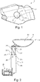
- figure 1 shows a schematic detailed representation of an embodiment of a vehicle 1 with an embodiment of a closure device 3, which is used to close a through-opening 5 in a vehicle body 7 of the vehicle 1. From the outside of the vehicle, an in figure 1 Covered interior accessible, in which a filling or connection device, in particular for supplying at least one substance or mixture of substances and / or energy in the vehicle 1 is arranged.
- the closure device 3 has a closure element 9, which can be moved between an open position, in which the through-opening 5 is released, and an in figure 1 illustrated closed position, in which the passage opening 5 is closed by the closure element 9, is displaceable.
- the closure element 9 is arranged at least in regions in the through-opening 5, wherein in the exemplary embodiment shown here in the figures it has in particular an outer surface 11 which, in the closed position, is flush, in particular flush with the surface, preferably aligned, with a surface immediately surrounding the through-opening 5 , is arranged on the outer body surface 13 of the vehicle body 7 adjoining the through-opening 5 .
- the closure element 9 is a flat component, in particular a panel or flap-like component, which is shaped in such a way that in its closed position it usually fits into the outer body skin as if the outer body skin were uninterrupted at this point.
- FIG figure 2 shows a detailed representation of the closure device 3 according to FIG figure 1 .
- the closure device 3 is set up, i.e. designed in such a way that when it is installed on the vehicle, it can move the closure element 9 from the closed position to the open position—and preferably back—with a combination of a translational movement and a pivoting movement into the interior of the vehicle body 7 .
- translational and rotational movements are superimposed at least over part of the adjustment path.
- the closure element 9 is assigned a drive 15, in particular a motor drive 15, for shifting between the closed position and the open position.
- the drive 15 is preferably designed as an electric motor.
- the closure device 3 has an adjustment device 17 which is set up to displace the closure element 9 between the open position and the closed position.
- the adjusting device 17 has a guide housing 19 that can be arranged spatially fixed on the vehicle body 7, preferably arranged spatially fixed on the vehicle body 7, a carrier element 21 being guided translationally, ie along a straight line, and pivotably in the guide housing 19.
- the carrier element 21 can be displaced translationally in the direction of a longitudinal axis of the guide housing 19 and is guided in the guide housing 19 such that it can pivot about the longitudinal axis of the guide housing 19 .
- the closure element 9 is fastened to the carrier element 21 .
- the closure element 9 can be carried along on the carrier element 21 and fixed to the carrier element 21 in a spatially fixed manner in the frame of reference.
- the advantage of the separate construction of the carrier element and the closure element is, among other things, that if the closure element should be painted in the color of the vehicle, this can be done before the closure element is connected to the carrier element.
- the guide housing 19 is tubular, with the carrier element 21 being mounted in the interior of the tubular guide housing 19 in such a way that it can be moved relative to the guide housing 19, which will be discussed in more detail below.
- Adjusting device 17 has a link guide 23, via which or with the aid of which carrier element 21 is coupled to guide housing 19 in such a way that carrier element 21 can be displaced and pivoted in translation relative to guide housing 19, which is fixed in place on the vehicle body.
- the guide housing 19 has at least one guide pin, here a plurality of guide pins 25, in particular four guide pins 25, with the cylindrical, rod-shaped or tubular support element 21 having at least one Guide recess, here a plurality of guide recesses 27, in particular four guide recesses 27 has.
- the guide pins 25 engage in the guide recesses 27 .
- the guide housing 19 it is also possible for the guide housing 19 to have at least one guide recess 27 , with the carrier element 21 having at least one guide pin 25 .
- the guide housing 19 can have both at least one guide pin 25 and at least one guide cutout 27 , with the carrier element 21 also having at least one guide cutout 27 and at least one guide pin 25 .
- the guide recesses 27 are designed here in particular as guide grooves.
- a respective guide recess 27 it is also possible for a respective guide recess 27 to be formed by a slit, in which case the guide pin to be brought into engagement with the slit would have to be dimensioned accordingly.
- the guide recesses 27 are designed to couple, ie to superimpose, at least in sections, a translatory relative movement between the carrier element 21 and the guide housing 19 with a pivoting movement of the carrier element 21 .
- the guide recesses 27 are in particular coiled at least in sections, in particular wound along helical lines around the longitudinal axis of the carrier element 21, which is also the longitudinal axis of the guide housing 19 at the same time. It is possible for the guide recesses 27 to be coiled along their entire extent. But it is also possible that they in sections, especially in one Initial section, in which the carrier element 21 is arranged in the closed position of the closure element 9, are formed in a straight line.
- a purely translational displacement of the carrier element 21 from the closed position in the direction of the open position can first take place, before this movement changes into a superimposition of a translational movement and a pivoting movement.
- the closure element 9 is first moved out of the through-opening provided on the bodywork side in the vertical direction before it is moved transversely to the through-opening behind the outer wall of the bodywork into the interior space reserved for this purpose.
- the link guide 23 consists of the at least one guide recess 27, in particular the guide groove, which forms the so-called link, and the guide pin 25 which is in engagement with it or engages in the guide recess 27 and which forms the so-called sliding block or has its function. is formed.
- the guide pin 25 preferably engages in the guide recess 27 with only a small amount of play, i.e. the outer diameter or the thickness of the guide pin 25 is less than the width of the guide recess 27.
- the guide pins 25 are placed in through holes, in particular bores or threaded holes in the outside of the guide housing 19, in particular screwed. These through-openings penetrate the outer wall of the guide housing 19 so that the guide pins can reach through them and engage in the respective guide recess.
- FIG figure 3 shows a detailed longitudinal section view of the adjusting device 17 according to FIG figure 2 .
- the carrier element 21 is connected to a tension element 29 so that it can be taken along and is shared with or by the tension element 29, so that the carrier element 21 is translated in the axial direction, i.e. here in the longitudinal direction of the guide housing 19, which is also the longitudinal center axis of the carrier element 21, when the tension element 29 is translated in this direction .
- tensile and compressive forces which point in the axial direction can be introduced into the carrier element 21 via the tensile element 29 .
- the tension element 29 is designed here as a toothed rack. It is coupled to a gear wheel 31 which in turn is drivingly connected to the drive 15 .
- a rotary movement of the drive 15 can thus be converted via the gear wheel 31 into a translatory movement, ie a purely linear movement of the pulling element 29 .
- the pulling element 29 is ultimately only displaced linearly along a straight line predetermined by the guide housing, with the respective direction of displacement being adjustable by the direction of rotation of the gear wheel 31 .
- Gear 31 is preferably connected to drive 15 via a particularly self-locking gear, so that forces acting from the outside in particular on closure element 9 cannot lead to its displacement, because such a displacement is blocked by the self-locking gear.
- the carrier element 21 has a cavity which is open at least on one side and into which the tension element 29 engages or protrudes.
- the tension element 29 is connected to the carrier element 21 via at least one pivot bearing, in this case via two pivot bearings 33, so that it can be carried along translationally and at the same time is rotationally decoupled, in such a way that, in particular, during a displacement movement of the tension element 29, this moves the carrier element 21 via at least one of the Pivot bearing 33 is subjected to a force, whereby the carrier element 21 is also displaced relative to the guide housing 19 .
- the carrier element 21 Due to the slotted guide 23 and its coiled or spirally extending guide recesses 27, the carrier element 21 is also pivoted about the translational axis of the tension element 29; there is therefore a superimposition of the translational and rotational or pivoting movement of the carrier element 21 . In contrast, the pulling element 29 is moved exclusively linearly. There is therefore no pivoting movement of the pulling element relative to the carrier element 21 .
- the closure element 9 is designed in particular as a tank cap or charging connection cap of the vehicle 1 .
- the adjustment device 17 and the vehicle 1, particularly space-saving kinematics can be provided for a closure element 9 of a vehicle 1 designed in particular as a tank or charging connection cover.
- closure device 3 can be designed as a completely pre-assembled structural unit and can be attached as a whole to the vehicle, preferably in one assembly step.
Landscapes
- Engineering & Computer Science (AREA)
- Mechanical Engineering (AREA)
- Life Sciences & Earth Sciences (AREA)
- Sustainable Development (AREA)
- Sustainable Energy (AREA)
- Chemical & Material Sciences (AREA)
- Combustion & Propulsion (AREA)
- Transportation (AREA)
- Cooling, Air Intake And Gas Exhaust, And Fuel Tank Arrangements In Propulsion Units (AREA)
- Power-Operated Mechanisms For Wings (AREA)
Description
- Die Erfindung betrifft eine Verschlussvorrichtung zum Verschließen einer Durchgangsöffnung in einer Fahrzeugkarosserie, gemäß Oberbegriff des Anspruchs 1, und ein Fahrzeug mit einer solchen Verschlussvorrichtung.
- Aus der
DE 20 2014 101 216 U1 geht eine Verschlussvorrichtung zum Verschließen einer Durchgangsöffnung in einer Fahrzeugkarosserie hervor, wobei über die Durchgangsöffnung ein Innenraum mit einer Befüllungs- oder Anschlusseinrichtung zugänglich ist. Die bekannte Verschlussvorrichtung weist ein Verschlusselement auf, das zwischen einer Offenstellung, in der die Durchgangsöffnung freigegeben ist, und einer Schließstellung, in der die Durchgangsöffnung durch das darin zumindest bereichsweise angeordnete Verschlusselement geschlossen ist, verlagerbar ist. Zur Verlagerung zwischen der Offenstellung und der Schließstellung ist das Verschlusselement typischerweise um eine ortsfeste Achse schwenkbar gelagert, wobei es eine reine Schwenkbewegung um die ortsfeste Achse vollführt. Somit ändert das Verschlusselement bei der Verlagerung von seiner Offenstellung in seine Schließstellung seine flächenmäßige Orientierung im Raum, das heißt insbesondere die Orientierung eines auf einer Außenfläche des Verschlusselements zumindest lokal senkrecht stehenden Normalenvektors, wodurch das Verschlusselement in der Offenstellung vergleichsweise viel Bauraum benötigt. Auch für die Schwenkbewegung selbst muss ein vergleichsweise großer Freiraum bereitgestellt werden, der anderweitig nicht genutzt werden kann. - Aus der
DE 10 2011 090 205 A1 geht eine Vorrichtung zum Verschließen einer in einer Karosserieaußenhaut vorgesehenen Öffnung hervor, über welche ein Tankeinfüllstutzen zugänglich ist. Die Öffnung ist mittels einer Tankklappe verschließbar, wobei die Tankklappe mittels eines Antriebs gegenüber der Karosserieaußenhaut nach außen hin in eine Offenstellung verstellbar ist. Dazu vollführt die Tankklappe eine überlagerte translatorische und rotatorische Bewegung, welche mittels einer Kulissenführung realisiert ist. Die Tankklappe ist an einem mit einem Permanentmagneten versehenen Trägerelement angebracht, welches in einer zentralen Bohrung eines Führungsgehäuses beweglich gelagert ist, wobei das Führungsgehäuse von einer Spule umgeben ist, mittels welcher ein magnetisches Feld zur Verlagerung des Trägerelements in axialer Richtung des Führungsgehäuses erzeugt werden kann. Diese Art von Antrieb ist relativ kostenintensiv, insbesondere auch aufgrund seiner Anordnung im Nassbereich des Fahrzeugs und der somit erforderlichen Abdichtung, und auch relativ störungsanfällig. Ferner ist eine exakte Positionierung der Tankklappe in ihren Endpositionen ohne entsprechende, in Bezug auf Lagetoleranzen kritische Anschläge nicht ohne weiteres möglich. - Aus der
DE 20 2011 050 412 U1 geht eine Tankdeckeleinheit für ein Kraftfahrzeug hervor, bei welcher ein eine Karosserieöffnung verschließender Verschlussdeckel mittels einer Kulissenführung gegenüber der Karosserieaußenhaut nach außen hin in eine Übergangsposition axial verfahrbar und zwischen der Übergangsposition und einer Öffnungsposition verdrehbar ist. Als Antrieb ist hierfür eine mittels eines Elektromotor antreibbare Spindel vorgesehen. - Aus der gattungsbildenden
DE 103 50 466 A1 geht eine Vorrichtung zum Verschließen einer Tankzugangsöffnung in einer Kraftfahrzeugaußenhaut hervor. - Der Erfindung liegt die Aufgabe zugrunde, eine Verschlussvorrichtung zum Verschließen einer Durchgangsöffnung in einer Fahrzeugkarosserie zu schaffen, die eine kompakte, raumsparende Bauweise ermöglicht und kostengünstig herstellbar sowie funktionssicher ist. Eine weitere Aufgabe ist es, ein Fahrzeug mit einer solchen Verschlussvorrichtung zu schaffen.
- Die Aufgabe wird gelöst, indem die Gegenstände der unabhängigen Ansprüche geschaffen werden. Vorteilhafte Ausgestaltungen ergeben sich aus den Unteransprüchen.
- Die Verschlussvorrichtung umfasst ein Verschlusselement zum Verschließen einer Durchgangsöffnung in einer Fahrzeugkarosserie, welches mittels eines Antriebs und einer Verstelleinrichtung in mehrere Funktionsstellungen, insbesondere zwischen einer die Durchgangsöffnung freigebenden Offenstellung und einer die Durchgangsöffnung abdeckenden beziehungsweise verschließenden Schließstellung verlagerbar ist, wobei das Verschlusselement in der Schließstellung zumindest bereichsweise in der Durchgangsöffnung angeordnet ist. Die Verschlussvorrichtung ist so eingerichtet, um das Verschlusselement von der Schließstellung in die Offenstellung und zurück mit einer Kombination aus einer translatorischen Bewegung und einer Schwenkbewegung in den Innenraum der Fahrzeugkarosserie, also in eine Position hinter der Karosserieaußenhaut zu verlagern, wodurch sich ein verringerter Bauraumbedarf für die Verlagerung selbst und für die Anordnung des Verschlusselements in der Offenstellung ergibt.
- Die Verschlussvorrichtung zeichnet sich dadurch aus, dass die Verstelleinrichtung ein an einer Fahrzeugkarosserie raumfest anordenbares Führungsgehäuse umfasst, in dem ein Trägerelement translatorisch und schwenkbar geführt ist, wobei das Trägerelement das Verschlusselement aufweist. Des Weiteren ist eine Kulissenführung vorgesehen, mittels der das Trägerelement gegenüber dem Führungsgehäuse translatorisch verlagerbar und schwenkbar ist. Weiterhin ist ein über wenigstens ein Drehlager mit dem Trägerelement translatorisch mitnehmbar und zugleich rotatorisch entkoppelt verbundenes Zugelement vorgesehen, das mittels des Antriebs translatorisch verlagerbar ist. Der Antrieb wirkt also nicht unmittelbar auf das Verschlusselement beziehungsweise das Trägerelement ein, sondern mittelbar über das Zugelement. Hierdurch ist eine gewisse beziehungsweise entsprechende Entkopplung zwischen Zugelement und Trägerelement möglich. Über das angetriebene, insbesondere motorisch angetriebene Zugelement sind Zugkräfte in das Trägerelement einleitbar, sodass dem Trägerelement über das Zugelement eine translatorische Bewegung vermittelt werden kann. Dies ermöglicht eine insgesamt schmale Ausführung der Verschlussvorrichtung, da der Antrieb in Verlagerungsrichtung des Trägerelements angeordnet werden kann. Aufgrund des vorgesehenen Drehlagers ist das Trägerelement von dem Zugelement rotatorisch entkoppelt. Dies ermöglicht eine Schwenkbewegung des Trägerelements, ohne dass das Zugelement verschwenkt werden muss. Vielmehr kann das Zugelement ausschließlich translatorisch verlagert werden, wobei - insbesondere durch die Kulissenführung - das Trägerelement zugleich translatorisch verlagert und verschwenkt werden kann.
- Das Drehlager ist vorzugsweise als Kugellager, als Gleitlager, als Wälzlager oder in anderer geeigneter Weise ausgebildet.
- Das Verschlusselement ist insbesondere mitnehmbar an dem Trägerelement befestigt, wobei es insbesondere relativ zu dem Trägerelement nicht verlagerbar ist, das heißt in einem mit dem Trägerelement mitbewegten Koordinatensystem raumfest gehalten ist. Das Führungsgehäuse ist demgegenüber an der Fahrzeugkarosserie ortsfest angeordnet, sodass sich eine Relativverlagerung des Verschlusselements relativ zu der Fahrzeugkarosserie ergibt, wenn das Trägerelement relativ zu dem Führungsgehäuse verlagert wird. Grundsätzlich ist es auch möglich, dass das Verschlusselement und das Trägerelement einteilig oder einstückig miteinander ausgebildet sind.
- Insbesondere kann aufgrund dieser Ausgestaltung der Verstelleinrichtung eine andere Schwenkachse verwendet werden als bei einer reinen Schwenkbewegung, wobei letztere insbesondere kein Verschwenken um eine Schwenkachse erlaubt, die quer oder zumindest im Wesentlichen senkrecht auf der Fahrzeugkarosserie im Bereich der Durchgangsöffnung steht. Bei einer solchen Verschwenkung würde nämlich das in der Schließstellung zumindest bereichsweise in der Durchgangsöffnung angeordnete Verschlusselement blockieren, da es an den Rändern der Durchgangsöffnung anstößt. Wird es allerdings durch die translatorische Bewegung aus der Durchgangsöffnung heraus verlagert, kann es dann auch um eine Achse verschwenkt werden, die im Wesentlichen senkrecht auf der Fahrzeugkarosserie im Bereich der Durchgangsöffnung steht, wobei es bevorzugt parallel hinter eine Wandung der Fahrzeugkarosserie verschwenkt werden kann. Die Verlagerung des Verschlusselements von der Offenstellung in die Schließstellung - und zurück - bedarf so nur eines sehr geringen Bauraums, wobei das Verschlusselement auch in der Schließstellung bauraumsparend hinter und parallel zu der Wandung der Fahrzeugkarosserie angeordnet werden kann.
- Unter einer Befüllungs- oder Anschlusseinrichtung wird insbesondere eine Einrichtung verstanden, die es erlaubt, einem Fahrzeug wenigstens einen Stoff oder ein Stoffgemisch und/oder Energie, sei es in Form von chemischer Energie, in Form von elektrischer Energie, insbesondere über eine galvanische Verbindung oder eine galvanisch getrennte Schnittstelle, beispielsweise induktiv, oder in anderer Weise zuzuführen. Insbesondere kann es sich bei der Befüllungs- oder Anschlusseinrichtung um einen Tankstutzen, insbesondere für Kraftstoff oder einen Zusatz- oder Hilfsstoff, eine Ladebuchse zur Zuführung von elektrischer Energie, insbesondere um eine Steckbuchse, einen Anschluss für ein induktives Laden, oder dergleichen handeln. Das Verschlusselement ist demnach insbesondere als Tankdeckel oder Ladeanschlussdeckel ausgebildet.
- Dass die Durchgangsöffnung in der Schließstellung durch das Verschlusselement geschlossen ist, bedeutet insbesondere, dass sie zu einem Äußeren der Fahrzeugkarosserie hin durch das Verschlusselement abgedeckt, das heißt von der Fahrzeugaußenseite her aufgrund der Anordnung des Verschlusselements in der Schließstellung unzugänglich ist. In der Offenstellung ist die Durchgangsöffnung dagegen zugänglich, sodass die Befüllungs- oder Anschlusseinrichtung bestimmungsgemäß verwendet und dem Fahrzeug insbesondere von außen durch die Durchgangsöffnung wenigstens ein Stoff oder Stoffgemisch und/oder Energie zugeführt werden kann.
- Unter einer Kombination aus einer translatorischen Bewegung und einer Schwenkbewegung wird insbesondere verstanden, dass das Verschlusselement entlang seines Verlagerungswegs von der Schließstellung in die Offenstellung - und zurück - zumindest abschnittsweise eine translatorische Bewegung sowie zumindest abschnittsweise - in gleichen oder anderen Abschnitten - eine Schwenkbewegung ausführt. Dabei ist es möglich, dass die translatorische Bewegung und die Schwenkbewegung in dem Sinne voneinander entkoppelt sind, dass in verschiedenen Abschnitten des Verlagerungswegs einerseits eine translatorische Bewegung und andererseits eine Schwenkbewegung erfolgt, wobei beispielsweise das Verschlusselement zunächst aus der Schließstellung mit einer translatorischen Bewegung entfernt, insbesondere in den Innenraum zurückgezogen wird, wobei es anschließend durch eine reine Schwenkbewegung in die Offenstellung verschwenkt wird. Unter einer Kombination aus einer translatorischen Bewegung und einer Schwenkbewegung wird aber auch eine Überlagerung einer translatorischen Bewegung und einer Schwenkbewegung verstanden, wobei das Verschlusselement zumindest abschnittsweise entlang seines Verlagerungswegs zwischen der Schließstellung und der Offenstellung eine Bewegungsbahn beschreibt, die aus einer Linearkombination, also einer Superposition, einer translatorischen Bewegungskomponente und einer Schwenkbewegungskomponente resultiert. Dabei ist es möglich, dass entlang des Verlagerungswegs zusätzlich Abschnitte mit einer reinen translatorischen Bewegung und/oder einer reinen Schwenkbewegung existieren, es ist aber auch möglich, dass das Verschlusselement entlang seines gesamten Verlagerungswegs einer Bewegungsbahn folgt, die aus einer Superposition einer translatorischen Bewegungskomponente mit einer rotatorischen Bewegungskomponente resultiert.
- Die translatorische Bewegung ist bevorzugt ausgehend von der Schließstellung des Verschlusselements in der Durchgangsöffnung nach innen in den Innenraum ausgerichtet, wobei eine Translationsrichtung oder Translationsachse der translatorischen Bewegung vorzugsweise lokal senkrecht auf einer Außenfläche des Verschlusselements und damit auch der Fahrzeugkarosserie steht. Ist die Verschlussvorrichtung an einem Fahrzeug seitlich angebracht, weist die Translationsachse bevorzugt - bei üblicher Wahl des Koordinatensystems für das Fahrzeug - zumindest im Wesentlichen in Y-Richtung, also in Fahrzeugbreitenrichtung.
- Die Schwenkbewegung erfolgt bevorzugt um eine Schwenkachse, die zumindest im Wesentlichen parallel, vorzugsweise parallel zu der Translationsachse ausgerichtet ist. Besonders bevorzugt erfolgt die Schwenkbewegung um die Translationsachse. Insbesondere erfolgt die Schwenkbewegung bevorzugt um eine in Querrichtung (y-Richtung) des Fahrzeugs verlaufende Achse. Auf diese Weise kann das Verschlusselement einerseits nach innen, also in eine gegenüber der Karosserieaußenfläche zurückversesetzte Position gezogen und andererseits hinter die Karosseriewandung geschwenkt werden.
- Gemäß einer Weiterbildung der Erfindung ist vorgesehen, dass die Außenfläche des Verschlusselements in der Schließstellung bündig mit einer die Durchgangsöffnung umgebenden Karosserieaußenfläche der Fahrzeugkarosserie angeordnet ist. Es ergibt sich so eine optisch besonders ansprechende, flächenbündige Anordnung des Verschlusselements in der Schließstellung mit der Fahrzeugkarosserie und insbesondere der Fahrzeugaußenhaut, sodass im Bereich der Verschlussvorrichtung keine optischen Vor- oder Rücksprünge entstehen.
- In der Offenstellung ist das Verschlusselement bevorzugt so weit in den Innenraum der Fahrzeugkarosserie hinein verlagert, dass es von außen, insbesondere bei in senkrechter Blickrichtung auf die Durchgangsöffnung, nicht mehr sichtbar ist. Das Fahrzeug weist dann auch in der Offenstellung eine optisch besonders ansprechende Anmutung auf.
- Gemäß einer Weiterbildung der Erfindung ist vorgesehen, dass der dem Verschlusselement zu dessen Verlagerung zwischen der Schließstellung und der Offenstellung - und zurück - zugeordnete Antrieb als motorischer Antrieb, besonders bevorzugt als elektromotorischer Antrieb, ausgebildet ist. Dies stellt für den Benutzer der Verschlussvorrichtung eine besonders komfortable Ausgestaltung dar, weil er das Verschlusselement dann nicht manuell betätigen muss.
- Es ist möglich, dass der Antrieb durch Betätigung eines Tasters aktivierbar ist. Besonders bevorzugt ist der Antrieb allerdings mit einer Steuereinrichtung verbunden, die eingerichtet ist, um den Antrieb automatisiert, insbesondere ereignisgesteuert, anzusteuern. Besonders bevorzugt ist an der Verschlussvorrichtung ein Näherungssensor angeordnet, der erkennt, wenn sich beispielsweise die Hand eines Benutzers, oder ein Zuführmittel zur Zuführung von Energie oder einem Stoff oder Stoffgemisch dem Verschlusselement nähert, wobei der Näherungssensor in diesem Fall ein Signal ausgibt, auf das hin der Antrieb zur Verlagerung des Verschlusselements aus seiner Schließstellung in seine Offenstellung angesteuert wird. Umgekehrt kann der Antrieb zur Verlagerung des Verschlusselements von dessen Offenstellung in seine Schließstellung angesteuert werden, wenn der Näherungssensor erkennt, dass die Zuführeinrichtung und/oder die Hand des Benutzers von der Verschlussvorrichtung wieder weg verlagert werden.
- Gemäß einer alternativen Ausgestaltung kann der Antrieb aber auch einen einfachen Seilzug, ein Gestänge oder dergleichen umfassen, mithin rein mechanisch ausgebildet sein, wobei er durch einen Benutzer des Fahrzeugs händisch betätigbar ist, beispielsweise von einem Fahrerplatz aus.
- Selbstverständlich ist es aber auch möglich, dass das Verschlusselement manuell, insbesondere durch direktes Angreifen an dem Verschlusselement selbst, von seiner Offenstellung in die Schließstellung - und zurück - verlagerbar ist.
- Gemäß einer bevorzugten Ausgestaltung der Verschlussvorrichtung ist vorgesehen, dass die Befüllungs- oder Anschlusseinrichtung - vorzugsweise zugleich mit der Verlagerung des Verschlusselements zwischen der Schließstellung und der Offenstellung - verlagerbar ist, wobei die Befüllungs- oder Anschlusseinrichtung insbesondere für ein Anschließen oder eine Befüllung von einer Ruheposition in Richtung des Äußeren der Fahrzeug-Karosserie, insbesondere in Fahrzeugquerrichtung, in eine Arbeitsposition verlagert werden kann, um das Befüllen und/oder Anschließen zu vereinfachen. Vor oder während der Verlagerung des Verschlusselements von der Offenstellung in die Schließstellung kann dann die Befüllungs- oder Anschlusseinrichtung wieder zurück in ihre Ruheposition, insbesondere in den Innenraum, vorzugsweise wiederum in Querrichtung des Fahrzeugs, verlagert werden. Es ist möglich, dass zur Verlagerung der Befüllungs- oder Anschlusseinrichtung ein separater Antrieb, insbesondere ein separater motorischer Antrieb, vorgesehen ist. Es ist aber auch möglich, dass die Befüllungs- oder Anschlusseinrichtung durch denselben Antrieb verlagerbar ist, der auch dem Verschlusselement zu dessen Verlagerung zugeordnet ist.
- Das Trägerelement ist insbesondere entlang einer Translationsachse translatorisch und um eine Schwenkachse schwenkbar gelagert. Vorzugsweise fällt die Schwenkachse mit der Translationsachse zusammen oder ist zumindest in Wesentlichen parallel, vorzugsweise parallel zu der Translationsachse ausgerichtet.
- Vorzugsweise weist die Verstelleinrichtung eine Verstellvorrichtung zur Verstellung einer Befüllungs- oder Anschlusseinrichtung auf, sodass diese mittels der Verstellvorrichtung zwischen einer Arbeitsposition und einer Ruheposition verlagert werden kann.
- Gemäß einer Weiterbildung der Erfindung ist vorgesehen, dass das Führungsgehäuse für das Trägerelement rohrförmig ausgebildet ist. Dies ermöglicht eine besonders einfache und stabile Aufnahme und Führung des Trägerelements in dem Führungsgehäuse. Insbesondere kann das Führungsgehäuse als Führungsrohr ausgebildet sein.
- Gemäß einer Weiterbildung der Erfindung ist vorgesehen, dass die Kulissenführung, mittels der das Trägerelement gegenüber dem Führungsgehäuse translatorisch verlagerbar und schwenkbar gekoppelt ist, insbesondere ausgebildet ist, um das Trägerelement in dem Führungsgehäuse entlang einer vorbestimmten Bewegungsbahn zu führen, vorzugsweise ein erstes Teil, ausgewählt aus dem Führungsgehäuse und dem Trägerelement, wenigstens einen Führungspin oder Führungsstift oder dergleichen aufweist, wobei ein zweites, von dem ersten Teil verschiedenes Teil, ausgewählt aus dem Trägerelement und dem Führungsgehäuse, wenigstens eine Führungsaussparung aufweist. Der wenigstens eine Führungsstift greift in die wenigstens eine Führungsaussparung ein, und die Führungsaussparung ist ausgebildet, um zumindest abschnittsweise eine translatorische Relativbewegung zwischen dem Trägerelement und dem Führungsgehäuse mit einer Schwenkbewegung des Trägerelements zu koppeln. Dies bedeutet insbesondere, dass die Führungsaussparung aufgrund ihrer räumlich-geometrischen Ausgestaltung und aufgrund der Kopplung des Führungsgehäuses mit dem Trägerelement über den in die Führungsaussparung eingreifenden Führungsstift bewirkt, dass eine translatorische Verlagerung des Trägerelements relativ zu dem Führungsgehäuse zumindest abschnittsweise von einer Schwenkbewegung des Trägerelements überlagert wird, oder dass umgekehrt einer Schwenkbewegung des Trägerelements eine translatorische Relativbewegung überlagert wird.
- Die mindestens eine Führungsaussparung ist bevorzugt zumindest abschnittsweise gewendelt, insbesondere ähnlich einer Spirale oder Schraubenfeder gewunden, ausgebildet, wobei sie sich bevorzugt um die Translationsachse der Translationsbewegung des Trägerelements windet. Es ist möglich, dass die Führungsaussparung entlang ihrer gesamten Erstreckung gewunden ausgebildet ist. Es ist aber auch möglich, dass sie zumindest abschnittsweise geradlinig ausgebildet ist. Insbesondere ist es möglich, dass die Führungsaussparung in einem Anfangsbereich, beginnend an einem Ort der Führungsaussparung, an welchem der Führungsstift in der Schließstellung angeordnet ist, über eine vorbestimmte Erstreckung in Richtung der Offenstellung geradlinig ausgebildet ist, bevor sie in einen gewundenen Verlauf übergeht. Auf diese Weise kann zunächst eine translatorische Bewegung des Verschlusselements aus der Schließstellung heraus bewirkt werden, wobei sich daran eine Überlagerung aus einer translatorischen Bewegung und einer Schwenkbewegung anschließt.
- Gemäß einer bevorzugten Ausgestaltung ist die Führungsaussparung als Führungsnut ausgebildet. Alternativ ist es möglich, dass die Führungsaussparung auch durch einen Schlitz gebildet sein kann.
- Bevorzugt ist der wenigstens eine Führungsstift an dem Führungsgehäuse angeordnet, wobei die wenigstens eine Führungsaussparung an dem Trägerelement angeordnet ist. Es ist aber auch eine umgekehrte Ausgestaltung möglich.
- Vorzugsweise weist die Kulissenführung eine Mehrzahl von Führungsstiften und eine Mehrzahl von Führungsaussparungen auf, wobei bevorzugt jedem Führungsstift eine Führungsaussparung und jeder Führungsaussparung ein Führungsstift zugeordnet sind. Die Führungsstifte und/oder Führungsaussparungen sind vorzugsweise - entlang einer Umfangsrichtung gesehen, die sich konzentrisch um die Translationsachse und/oder die Schwenkachse erstreckt - symmetrisch, insbesondere in gleichen Winkelabständen zueinander, angeordnet. Besonders bevorzugt weist die Kulissenführung vier Führungsstifte und vier Führungsaussparungen auf.
- Gemäß einer Weiterbildung der Erfindung ist vorgesehen, dass das Zugelement als Zahnstange ausgebildet ist. Dies stellt eine besonders einfache und einfach anzutreibende Ausgestaltung des Zugelements dar. Die Zahnstange weist außer einem Zähne aufweisenden Längsabschnitt auch noch einen Kopplungsabschnitt auf, in dessen Bereich die Zahnstange/das Zugelement mit dem Trägerelement gekoppelt ist.
- Das Zugelement wirkt vorzugsweise mit einem Zahnrad zusammen, welches durch einen Motor, insbesondere durch einen Elektromotor, angetrieben ist. Auf diese Weise kann eine Rotationsbewegung des Motors in eine Translationsbewegung des Zugelements umgewandelt werden. Der Motor ist vorzugsweise über ein Getriebe mit dem Zahnrad antriebswirkverbunden. Das Getriebe ist vorzugsweise selbsthemmend ausgebildet. In diesem Fall ist eine Verlagerung des Verschlusselements nur durch Aktivieren des Motors möglich, da die Selbsthemmung des Getriebes eine Verlagerung des Verschlusselements verhindert, wenn Kräfte in das Verschlusselement eingeleitet werden, ohne dass der Motor betrieben wird.
- Gemäß einer Weiterbildung der Erfindung ist vorgesehen, dass die Verschlussvorrichtung eine Verstelleinrichtung nach einem der zuvor beschriebenen Ausführungsbeispiele aufweist. Insbesondere ist dem Verschlusselement eine Verstelleinrichtung nach einem der zuvor beschriebenen Ausführungsbeispiele zu dessen Verlagerung zwischen der Schließstellung und der Offenstellung - und zurück - zugeordnet. Das Verschlusselement ist dabei mitnehmbar an dem Trägerelement angeordnet.
- Die Aufgabe wird schließlich auch gelöst, indem ein Fahrzeug geschaffen wird, welches eine Verschlussvorrichtung nach einem der zuvor beschriebenen Ausführungsbeispiele aufweist. Dabei ergeben sich in Zusammenhang mit dem Fahrzeug insbesondere die Vorteile, die bereits in Zusammenhang mit der Verschlussvorrichtung erläutert wurden.
- Das Verschlusselement des Fahrzeugs ist insbesondere als Tank- oder Ladeanschlussdeckel ausgebildet.
- Die Erfindung wird im Folgenden anhand der Zeichnung näher erläutert. Dabei zeigen:
- Fig. 1
- eine Detaildarstellung eines Ausführungsbeispiels eines Fahrzeugs mit einem Ausführungsbeispiel einer Verschlussvorrichtung;
- Fig. 2
- eine Detaildarstellung des Ausführungsbeispiels der Verschlussvorrichtung gemäß
Figur 1 mit einem Ausführungsbeispiel einer Verstelleinrichtung zum Verlagern des Verschlusselements und - Fig. 3
- eine schematische Detail-Schnittdarstellung der Verstelleinrichtung gemäß
Figur 2 . -
Figur 1 zeigt eine schematische Detaildarstellung eines Ausführungsbeispiels eines Fahrzeugs 1 mit einem Ausführungsbeispiel einer Verschlussvorrichtung 3, die zum Verschließen eine Durchgangsöffnung 5 in einer Fahrzeugkarosserie 7 des Fahrzeugs 1 dient. Über die Durchgangsöffnung 5 ist von der Fahrzeugaußenseite her ein inFigur 1 verdeckter Innenraum zugänglich, in dem eine Befüllungs- oder Anschlusseinrichtung, insbesondere zur Zufuhr von wenigstens einem Stoff oder Stoffgemisch und/oder von Energie in das Fahrzeug 1 angeordnet ist. - Die Verschlussvorrichtung 3 weist ein Verschlusselement 9 auf, das zwischen einer Offenstellung, in der die Durchgangsöffnung 5 freigegeben ist, und einer in
Figur 1 dargestellten Schließstellung, in der die Durchgangsöffnung 5 durch das Verschlusselement 9 geschlossen ist, verlagerbar ist. Das Verschlusselement 9 ist in der Schließstellung zumindest bereichsweise in der Durchgangsöffnung 5 angeordnet, wobei es bei dem hier in den Figuren dargestellten Ausführungsbeispiel insbesondere eine Außenfläche 11 aufweist, die in der Schließstellung bündig, insbesondere flächenbündig, vorzugsweise fluchtend, mit einer die Durchgangsöffnung 5 unmittelbar umgebenden, an die Durchgangsöffnung 5 angrenzenden Karosserieaußenfläche 13 der Fahrzeugkarosserie 7 angeordnet ist. Das Verschlusselement 9 ist ein flächiges, insbesondere tafel- oder klappenähnliches Bauteil, das so geformt ist, dass es sich in seiner Schließstellung üblicherweise in die Karosserieaußenhaut optisch so einfügt, als wenn die Karosserieaußenhaut an dieser Stelle ununterbrochen wäre. -
Figur 2 zeigt eine Detaildarstellung der Verschlussvorrichtung 3 gemäßFigur 1 . Gleiche und funktionsgleiche Elemente sind mit gleichen Bezugszeichen versehen, sodass insofern auf die vorangegangene Beschreibung verwiesen wird. Die Verschlussvorrichtung 3 ist eingerichtet, das heißt so ausgebildet, damit diese im am Fahrzeug verbauten Zustand das Verschlusselement 9 von der Schließstellung in die Offenstellung - und bevorzugt zurück - mit einer Kombination aus einer translatorischen Bewegung und einer Schwenkbewegung in den Innenraum der Fahrzeugkarosserie 7 verlagern kann. Bei der bestimmungsgemäßen Verstellung des Verschlusselements 9 findet also zumindest über eine Teilstrecke des Verstellweges eine Überlagerung von Translations- und Rotationsbewegungen statt. Grundsätzlich ist es auch möglich, dass das Verschlusselement 9 über eine Teilstrecke seines Verstellweges eine reine Linearbewegung entlang einer Gerade oder Achse ausführt. Diese Art einer Hubbewegung kann dazu dienen, das Verschlusselement in die Durchgangsöffnung einzubringen oder aus dieser heraus zu bewegen, ohne dass dabei das Verschlusselement gegen benachbarte, an die Durchgangsöffnung angrenzende beziehungsweise diese begrenzende Karosseriebereiche, insbesondere Karosserieaußenhautbereiche stößt. - Auf diese Weise ist es insbesondere möglich, die Verlagerung des Verschlusselements 9 selbst sehr bauraumsparend auszugestalten und zugleich auch Bauraum in der Offenstellung des Verschlusselements 9 einzusparen. Dieses kann insbesondere ausgehend von der in
Figur 1 dargestellten Schließstellung in den Innenraum eingezogen und dann hinter die Fahrzeugkarosserie 7 verschwenkt werden, sodass es in der Offenstellung - wie auch in der Schließstellung - im Wesentlichen parallel zu der Fahrzeugkarosserie 7 und insbesondere zu der Karosserieaußenfläche 13 angeordnet ist, wodurch es auch in der Offenstellung wenig Bauraum beansprucht. Hierdurch ist das Verschlusselement 9 vor äußeren Einflüssen, beispielsweise einer ungewollten manuellen Manipulation durch Dritte, geschützt im Innenraum angeordnet. - Dem Verschlusselement 9 ist ein Antrieb 15, insbesondere ein motorischer Antrieb 15, zur Verlagerung zwischen der Schließstellung und der Offenstellung zugeordnet. Der Antrieb 15 ist bevorzugt als Elektromotor ausgebildet.
- Die Verschlussvorrichtung 3 weist eine Verstelleinrichtung 17 auf, die eingerichtet ist zum Verlagern des Verschlusselements 9 zwischen der Offenstellung und der Schließstellung. Die Verstelleinrichtung 17 weist ein an der Fahrzeugkarosserie 7 raumfest anordenbares, vorzugsweise an der Fahrzeugkarosserie 7 raumfest angeordnetes Führungsgehäuse 19 auf, wobei in dem Führungsgehäuse 19 ein Trägerelement 21 translatorisch, das heißt entlang einer Geraden, und schwenkbar geführt ist. Insbesondere ist das Trägerelement 21 in Richtung einer Längsachse des Führungsgehäuses 19 translatorisch verlagerbar und um die Längsachse des Führungsgehäuses 19 schwenkbar in dem Führungsgehäuse 19 geführt.
- An dem Trägerelement 21 ist das Verschlusselement 9 befestigt. Insbesondere ist hier das Verschlusselement 9 an dem Trägerelement 21 mitnehmbar und im Bezugssystem des Trägerelements 21 raumfest an diesem befestigt. Vorteilhaft an der getrennten Ausbildung von Trägerelement und Verschlusselement ist unter anderem, dass falls das Verschlusselement in Fahrzeugfarbe lackiert werden sollte, dies erfolgen kann, bevor das Verschlusselement mit dem Trägerelement verbunden wird.
- Das Führungsgehäuse 19 ist rohrförmig ausgebildet, wobei das Trägerelement 21 in dem Inneren des rohrförmigen Führungsgehäuses 19 so gelagert ist, dass es relativ gegenüber dem Führungsgehäuse 19 bewegbar ist, worauf im Folgenden noch näher eingegangen wird.
- Die Verstelleinrichtung 17 weist eine Kulissenführung 23 auf, über die beziehungsweise mit deren Hilfe das Trägerelement 21 mit dem Führungsgehäuse 19 so gekoppelt ist, dass das Trägerelement 21 dabei relativ gegenüber dem an der Fahrzeugkarosserie ortsfest fixierten Führungsgehäuse 19 translatorisch verlagerbar und schwenkbar ist. Dabei weist bei dem hier dargestellten Ausführungsbeispiel das Führungsgehäuse 19 wenigstens einen Führungsstift, hier eine Mehrzahl von Führungsstiften 25, insbesondere vier Führungsstifte 25, auf, wobei das zylinder-, stab- oder rohrförmige Trägerelement 21 an seiner Außenseite, das heißt an seiner Mantelfläche wenigstens eine Führungsaussparung, hier eine Mehrzahl von Führungsaussparungen 27, insbesondere vier Führungsaussparungen 27, aufweist. Die Führungsstifte 25 greifen in die Führungsaussparungen 27 ein. Es ist alternativ auch möglich, dass das Führungsgehäuse 19 wenigstens eine Führungsaussparung 27 aufweist, wobei das Trägerelement 21 wenigstens einen Führungsstift 25 aufweist. Es ist auch möglich, dass das Führungsgehäuse 19 sowohl wenigstens einen Führungsstift 25 als auch wenigstens eine Führungsaussparung 27 aufweist, wobei auch das Trägerelement 21 wenigstens eine Führungsaussparung 27 und wenigstens einen Führungsstift 25 aufweist.
- Die Führungsaussparungen 27 sind hier insbesondere als Führungsnuten ausgebildet. Grundsätzlich ist es auch möglich, das eine jeweilige Führungsaussparung 27 durch einen Schlitz gebildet ist, wobei hierzu der mit dem Schlitz in Eingriff zu bringende Führungsstift entsprechend zu dimensionieren wäre.
- Die Führungsaussparungen 27 sind ausgebildet, um zumindest abschnittsweise eine translatorische Relativbewegung zwischen dem Trägerelement 21 und dem Führungsgehäuse 19 mit einer Schwenkbewegung des Trägerelements 21 zu koppeln, das heißt zu überlagern. Hierzu sind die Führungsaussparungen 27 insbesondere zumindest abschnittsweise gewendelt, insbesondere entlang von Schraubenlinien um die Längsachse des Trägerelements 21, die zugleich auch die Längsachse des Führungsgehäuses 19 ist, gewunden ausgebildet. Es ist möglich, dass die Führungsaussparungen 27 entlang ihrer gesamten Erstreckung gewendelt ausgebildet sind. Es ist aber auch möglich, dass sie abschnittsweise, insbesondere in einem Anfangsabschnitt, in welchem das Trägerelement 21 in der Schließstellung des Verschlusselements 9 angeordnet ist, geradlinig ausgebildet sind. In diesem Fall kann zunächst eine rein translatorische Verlagerung des Trägerelements 21 aus der Schließstellung heraus in Richtung der Offenstellung erfolgen, bevor diese Bewegung in eine Überlagerung aus einer Translationsbewegung und einer Schwenkbewegung übergeht. So wird das Verschlusselement 9 also aus der karosserieseitig vorgesehenen Durchgangsöffnung zunächst in senkrechter Richtung herausbewegt, bevor es quer zur Durchgangsöffnung hinter die Außenwand der Karosserie in den dafür freigehaltenen Innenraum bewegt wird.
- Die Führungsaussparungen 27 bewirken jedenfalls abschnittsweise aufgrund ihrer räumlich-geometrischen Ausgestaltung und insbesondere aufgrund ihrer Wendelung, dass einer translatorischen Verlagerung des Trägerelements 21 in Richtung der Längsachse des Führungsgehäuses 19, mithin in
Figur 2 insbesondere in vertikaler Richtung, eine Schwenkbewegung um diese Längsachse überlagert wird. - Festzuhalten bleibt, dass die Kulissenführung 23 aus der mindestens einen Führungsaussparung 27, insbesondere Führungsnut, welche die sogenannte Kulisse bildet, und dem mit dieser in Eingriff stehenden beziehungsweise in die Führungsaussparung 27 eingreifenden Führungsstift 25, welcher quasi den sogenannten Kulissenstein bildet beziehungsweise dessen Funktion innehat, gebildet ist. Der Führungsstift 25 greift vorzugsweise mit nur geringem Spiel in die Führungsaussparung 27, das heißt der Außendurchmesser beziehungsweise die Dicke des Führungsstiftes 25 ist geringer als die Breite der Führungsaussparung 27.
- Bei dem anhand der
Figur 2 beschriebenen Ausführungsbeispiel der Verschlussvorrichtung 3 sind die Führungsstifte 25 in Durchgangsöffnungen, insbesondere Bohrungen beziehungsweise Gewindebohrungen in der Außenseite des Führungsgehäuses 19 eingebracht, insbesondere eingeschraubt. Diese Durchgangsöffnungen durchdringen die Außenwand des Führungsgehäuses 19, so dass die Führungsstifte diese durchgreifen und in die jeweilige Führungsaussparung eingreifen können. -
Figur 3 zeigt eine Detail-Längsschnittdarstellung der Verstelleinrichtung 17 gemäßFigur 2 . Gleiche und funktionsgleiche Elemente sind mit gleichen Bezugszeichen versehen, sodass insofern auf die vorangegangene Beschreibung verwiesen wird. Das Trägerelement 21 ist mit einem Zugelement 29 mitnehmbar verbunden und gemeinsam mit dem beziehungsweise durch das Zugelement 29 translatorisch verlagerbar, sodass das Trägerelement 21 in axialer Richtung, das heißt hier in Längsrichtung des Führungsgehäuses 19, welche zugleich die Längsmittelachse des Trägerelements 21 ist, translatorisch verlagert wird, wenn das Zugelement 29 in dieser Richtung translatorisch verlagert wird. Über das Zugelement 29 sind insbesondere Zug- und Druckkräfte, die in axiale Richtung weisen, in das Trägerelement 21 einleitbar. - Das Zugelement 29 ist hier als Zahnstange ausgebildet. Es ist mit einem Zahnrad 31 gekoppelt, welches seinerseits mit dem Antrieb 15 antriebswirkverbunden ist. Eine Drehbewegung des Antriebs 15 kann so über das Zahnrad 31 in eine translatorische Bewegung, also eine reine Linearbewegung des Zugelements 29 umgesetzt werden. Mit anderen Worten, das Zugelement 29 wird letztlich nur linear entlang einer durch das Führungsgehäuse vorgegebene Gerade verschoben, wobei die jeweilige Verschieberichtung durch die Drehrichtung des Zahnrads 31 einstellbar ist.
- Vorzugsweise ist das Zahnrad 31 über ein insbesondere selbsthemmendes Getriebe mit dem Antrieb 15 verbunden, sodass von außen insbesondere an dem Verschlusselement 9 angreifende Kräfte nicht zu dessen Verlagerung führen können, weil eine solche Verlagerung durch das selbsthemmende Getriebe gesperrt wird.
- Das Trägerelement 21 weist einen Hohlraum auf, der zumindest einseitig offen ist und in welchen das Zugelement 29 eingreift beziehungsweise hineinragt. In diesem Hohlbeziehungsweise Aufnahmeraum ist das Zugelement 29 über wenigstens ein Drehlager, hier über zwei Drehlager 33, translatorisch mitnehmbar und zugleich rotatorisch entkoppelt mit dem Trägerelement 21 verbunden, derart also, dass insbesondere bei einer Verschiebebewegung des Zugelements 29 dieses das Trägerelement 21 über zumindest eines der Drehlager 33 mit einer Kraft beaufschlagt, wodurch das Trägerelement 21 ebenfalls relativ gegenüber dem Führungsgehäuse 19 verschoben wird. Aufgrund der Kulissenführung 23 und deren gewendelten beziehungsweise spiralförmig verlaufenden Führungsaussparungen 27 wird dabei das Trägerelement 21 auch um die Translationsachse des Zugelements 29 verschwenkt; es findet also eine Überlagerung der Translations- und Rotations- beziehungsweise Schwenkbewegung des Trägerelements 21 statt. Demgegenüber wird das Zugelement 29 ausschließlich linear bewegt. Es findet also keine Schwenkbewegung des Zugelements relativ gegenüber dem Trägerelement 21 statt.
- Das Verschlusselement 9 ist insbesondere als Tankdeckel oder Ladeanschlussdeckel des Fahrzeugs 1 ausgebildet.
- Mit der hier vorgeschlagenen Verschlussvorrichtung 3, der Verstelleinrichtung 17 und dem Fahrzeug 1 kann eine besonders bauraumsparende Kinematik für ein insbesondere als Tank- oder Ladeanschlussdeckel ausgebildetes Verschlusselement 9 eines Fahrzeugs 1 bereitgestellt werden.
- Festzuhalten bleibt, dass die Verschlussvorrichtung 3 als komplett vormontierbare Baueinheit ausgebildet werden kann beziehungsweise ist und als Ganzes am Fahrzeug, vorzugsweise in einem Montageschritt, angebracht werden kann.
Claims (7)
- Verschlussvorrichtung (3) zum Verschließen einer Durchgangsöffnung (5) in einer Fahrzeugkarosserie (7), wobei über die Durchgangsöffnung (5) ein Innenraum mit einer Befüllungs- oder Anschlusseinrichtung zugänglich ist, mit einem mittels einer Verstelleinrichtung (17) verlagerbaren Verschlusselement (9), das mittels eines Antriebs (15) zwischen einer Offenstellung, in der die Durchgangsöffnung (5) freigegeben ist, und einer Schließstellung, in der die Durchgangsöffnung (5) durch das Verschlusselement (9) geschlossen ist, verlagerbar ist, wobei das Verschlusselement (9) in der Schließstellung zumindest bereichsweise in der Durchgangsöffnung (5) angeordnet ist, und wobei die Verschlussvorrichtung (3) eingerichtet ist, um das Verschlusselement (9) von der Schließstellung in die Offenstellung mit einer Kombination aus einer translatorischen Bewegung und einer Schwenkbewegung in den Innenraum der Fahrzeugkarosserie (7) zu verlagern,
dadurch gekennzeichnet,- dass die Verstelleinrichtung (17) ein an einer Fahrzeugkarosserie (7) raumfest anordenbares Führungsgehäuse (19) umfasst, in dem ein Trägerelement (21) translatorisch und schwenkbar geführt ist, wobei das Trägerelement (21) das Verschlusselement (9) aufweist,- dass eine Kulissenführung (23) vorgesehen ist, mittels der das Trägerelement (21) gegenüber dem Führungsgehäuse (19) translatorisch verlagerbar und schwenkbar ist,- dass ein über wenigstens ein Drehlager (33) mit dem Trägerelement (21) translatorisch mitnehmbar und zugleich rotatorisch entkoppelt verbundenes Zugelement (29) vorgesehen ist, das mittels des Antriebs (15) translatorisch verlagerbar ist. - Verschlussvorrichtung (3) nach Anspruch 1,
dadurch gekennzeichnet, dass
das Verschlusselement (9) eine Außenfläche (11) aufweist, die in der Schließstellung bündig mit einer die Durchgangsöffnung (5) umgebenden Karosserieaußenfläche (13) der Fahrzeugkarosserie (7) angeordnet ist. - Verschlussvorrichtung (3) nach einem der vorhergehenden Ansprüche,
dadurch gekennzeichnet, dass
der dem Verschlusselement (9) zu dessen Verlagerung zwischen der Schließstellung und der Offenstellung zugeordnete Antrieb (15) ein motorischer Antrieb (15) ist. - Verschlussvorrichtung (3) nach Anspruch 1,
dadurch gekennzeichnet, dass
das Führungsgehäuse (19) rohrförmig ausgebildet ist. - Verschlussvorrichtung (3) nach Anspruch 1,
dadurch gekennzeichnet, dass
die Kulissenführung (23) ein erstes Teil, ausgewählt aus dem Führungsgehäuse (19) und dem Trägerelement (21), welches wenigstens einen Führungsstift (25) aufweist, und ein zweites, von dem ersten Teil verschiedenes Teil, ausgewählt aus dem Trägerelement (21) und dem Führungsgehäuse (19), welches wenigstens eine Führungsaussparung (27) aufweist, umfasst, wobei der wenigstens eine Führungsstift (25) in die wenigstens eine Führungsaussparung (27) eingreift, und wobei die wenigstens eine Führungsaussparung (27) ausgebildet ist, um zumindest abschnittsweise eine translatorische Relativbewegung zwischen dem Trägerelement (21) und dem Führungsgehäuse (19) mit einer Schwenkbewegung des Trägerelements (21) zu koppeln. - Verschlussvorrichtung (3) nach Anspruch 1,
dadurch gekennzeichnet, dass
das Zugelement (29) als Zahnstange ausgebildet ist. - Fahrzeug (1) mit einer Verschlussvorrichtung (3) nach einem der Ansprüche 1 bis 6, wobei das Verschlusselement (9) als Tankdeckel oder als Ladeanschlussdeckel ausgebildet ist.
Applications Claiming Priority (2)
| Application Number | Priority Date | Filing Date | Title |
|---|---|---|---|
| DE102017008108.5A DE102017008108B4 (de) | 2017-08-26 | 2017-08-26 | Verschlussvorrichtung zum Verschließen einer Durchgangsöffnung in einer Fahrzeugkarosserie und Fahrzeug mit einer solchen Verschlussvorrichtung |
| PCT/EP2018/066180 WO2019042616A1 (de) | 2017-08-26 | 2018-06-19 | Verschlussvorrichtung zum verschliessen einer durchgangsöffnung in einer fahrzeugkarosserie und fahrzeug mit einer solchen verschlussvorrichtung |
Publications (2)
| Publication Number | Publication Date |
|---|---|
| EP3681750A1 EP3681750A1 (de) | 2020-07-22 |
| EP3681750B1 true EP3681750B1 (de) | 2022-04-13 |
Family
ID=60676348
Family Applications (1)
| Application Number | Title | Priority Date | Filing Date |
|---|---|---|---|
| EP18746098.5A Active EP3681750B1 (de) | 2017-08-26 | 2018-06-19 | Verschlussvorrichtung zum verschliessen einer durchgangsöffnung in einer fahrzeugkarosserie und fahrzeug mit einer solchen verschlussvorrichtung |
Country Status (5)
| Country | Link |
|---|---|
| US (1) | US11161405B2 (de) |
| EP (1) | EP3681750B1 (de) |
| CN (1) | CN111051112B (de) |
| DE (1) | DE102017008108B4 (de) |
| WO (1) | WO2019042616A1 (de) |
Cited By (1)
| Publication number | Priority date | Publication date | Assignee | Title |
|---|---|---|---|---|
| US12560002B2 (en) | 2022-04-26 | 2026-02-24 | Illinois Tool Works Inc. | Device for aligning covers for vehicles |
Families Citing this family (16)
| Publication number | Priority date | Publication date | Assignee | Title |
|---|---|---|---|---|
| DE102018109474A1 (de) * | 2018-04-20 | 2019-10-24 | Dr. Ing. H.C. F. Porsche Aktiengesellschaft | Ladedosendeckel für ein elektrisch betriebenes Kraftfahrzeug |
| DE102018009010B4 (de) * | 2018-11-16 | 2024-04-25 | Easelink Gmbh | Unterbodenladeeinheit sowie Fahrzeug mit einer Unterbodenladeeinheit |
| DE102019106436A1 (de) * | 2019-03-13 | 2020-09-17 | Huf Hülsbeck & Fürst GmbH & Co KG | Kraftfahrzeug-Klappen-System |
| CN111301537A (zh) * | 2020-03-09 | 2020-06-19 | 北京华商三优新能源科技有限公司 | 充电门结构及具有其的车辆 |
| DE102020130235A1 (de) * | 2020-11-16 | 2022-05-19 | Hbpo Gmbh | Motorbetriebene Abdeckvorrichtung |
| DE102021211117A1 (de) | 2021-10-01 | 2023-04-06 | Volkswagen Aktiengesellschaft | Kraftfahrzeug |
| WO2023102902A1 (zh) * | 2021-12-10 | 2023-06-15 | 浙江吉利控股集团有限公司 | 一种车辆及其充电口的开闭结构 |
| DE102022100995B4 (de) | 2022-01-17 | 2023-08-10 | Weber Gmbh & Co. Kg Kunststofftechnik Und Formenbau | Öffnungs- und Schließvorrichtung für eine Lade- und/oder Tankmulde eines Fahrzeugs |
| DE102022110178A1 (de) * | 2022-04-27 | 2023-11-02 | Hbpo Gmbh | Motorbetriebene Abdeckvorrichtung |
| DE102022119787A1 (de) * | 2022-08-05 | 2024-02-08 | Paragon Gmbh & Co. Kgaa | Deckelvorrichtung und Kraftfahrzeug mit einer solchen Deckelvorrichtung |
| CN115195597B (zh) * | 2022-08-12 | 2025-04-22 | 浙江吉利控股集团有限公司 | 外后视镜机构 |
| DE102022121659A1 (de) * | 2022-08-26 | 2024-02-29 | Kiekert Aktiengesellschaft | Ladesteckdose für ein Elektro- oder Hybridfahrzeug |
| US12545132B2 (en) | 2022-10-04 | 2026-02-10 | Illinois Tool Works Inc. | Actuating mechanism for actuating covers for vehicles |
| DE102023111105A1 (de) * | 2023-04-28 | 2024-10-31 | Kiekert Aktiengesellschaft | Ladesteckverbinder für Elektro- und Hybridfahrzeuge |
| CN116674657B (zh) * | 2023-05-04 | 2026-05-01 | 广东东箭汽车智能系统有限公司 | 一种口盖结构以及机动设备 |
| DE102023120352B4 (de) * | 2023-08-01 | 2025-05-22 | Schaeffler Technologies AG & Co. KG | Fahrzeugeinheit eines konduktiven Ladesystems mit einer Hub-Schwenk-Kulisse |
Family Cites Families (22)
| Publication number | Priority date | Publication date | Assignee | Title |
|---|---|---|---|---|
| EP0582025B1 (de) * | 1992-08-07 | 1996-03-20 | Bing-Jye Cherng | Angetriebener Kraftstofftankdeckel für Kraftfahrzeuge |
| DE19812384A1 (de) * | 1998-03-20 | 1999-09-23 | Temtec Fahrzeugtechnik Entwicklungsgesellschaft Mbh | Kraftstoffbehälterverschluß |
| DE19935454C2 (de) * | 1999-07-28 | 2001-05-31 | Alfmeier Praez Ag | Vorrichtung zum automatischen Öffnen und Schließen des Tankdeckels und der Tankklappe eines Kraftfahrzeuges |
| DE10315513A1 (de) * | 2003-04-04 | 2004-10-28 | Temtec Fahrzeugtechnik Entwicklungsgesellschaft Mbh | Kraftstoffbehälterverschluss |
| DE10350466B4 (de) | 2003-10-29 | 2006-04-06 | Alfred Engelmann Holding Gmbh | Vorrichtung zum Verschließen einer Zugangsöffnung in einer Kraftfahrzeugaußenhaut |
| WO2005084987A1 (en) * | 2004-02-28 | 2005-09-15 | Naim Guendouz | Automatic gas cap actuator with redundancy |
| DE102004010294B4 (de) * | 2004-03-03 | 2007-05-03 | Itw Automotive Products Gmbh & Co. Kg | Tankmulde für Automobile |
| FR2949394B1 (fr) * | 2009-09-02 | 2011-12-23 | Coutier Moulage Gen Ind | Trappe a carburant motorisee pour vehicules automobiles |
| KR101209793B1 (ko) * | 2010-08-31 | 2012-12-10 | 현대자동차주식회사 | 자동차의 연료도어 개폐장치 |
| DE202011050412U1 (de) * | 2011-06-10 | 2011-08-17 | Richard Fritz Gmbh + Co. Kg | Tankdeckeleinheit für ein Kraftfahrzeug |
| KR101284299B1 (ko) * | 2011-06-13 | 2013-07-08 | 현대자동차주식회사 | 차량용 연료도어 개폐장치 |
| DE102011113907A1 (de) * | 2011-09-21 | 2012-04-05 | Daimler Ag | Verstellbare Verkleidung für einen Kraftwagen |
| DE102011090205A1 (de) | 2011-12-30 | 2013-07-04 | Dr. Ing. H.C. F. Porsche Ag | Verschlusselement mit Betätigungsvorrichtung |
| DE102013003668A1 (de) * | 2013-03-02 | 2014-03-20 | Daimler Ag | Fahrzeug mit einem Haubenelement |
| US9656544B2 (en) * | 2013-09-17 | 2017-05-23 | GM Global Technology Operations LLC | Motor vehicle flap arrangement |
| JP6211909B2 (ja) * | 2013-12-02 | 2017-10-11 | 株式会社ニフコ | リッド装置 |
| US9669708B2 (en) * | 2014-01-31 | 2017-06-06 | Mark Steven Dunger | Retractable vehicle fueling receptacle cover |
| DE202014101216U1 (de) | 2014-02-03 | 2015-05-15 | Brose Fahrzeugteile Gmbh & Co. Kommanditgesellschaft, Coburg | Verschlussvorrichtung für eine Befüllungs- oder Anschlussöffnung an einem Fahrzeug |
| JP6297451B2 (ja) * | 2014-08-26 | 2018-03-20 | 愛三工業株式会社 | 燃料供給装置 |
| DE202016100445U1 (de) * | 2016-01-29 | 2017-05-03 | Brose Fahrzeugteile Gmbh & Co. Kommanditgesellschaft, Coburg | Verschlussvorrichtung für eine Befüllungsöffnung oder ein Anschlusselement an einem Fahrzeug mit einem Notentriegelungsmechanismus |
| CN109972937B (zh) * | 2017-12-27 | 2022-05-10 | 伊利诺斯工具制品有限公司 | 加油或充电口门锁总成 |
| KR102579355B1 (ko) * | 2018-09-11 | 2023-09-18 | 현대자동차주식회사 | 연료필러도어의 개폐장치 |
-
2017
- 2017-08-26 DE DE102017008108.5A patent/DE102017008108B4/de active Active
-
2018
- 2018-06-19 US US16/641,972 patent/US11161405B2/en active Active
- 2018-06-19 CN CN201880055087.9A patent/CN111051112B/zh active Active
- 2018-06-19 EP EP18746098.5A patent/EP3681750B1/de active Active
- 2018-06-19 WO PCT/EP2018/066180 patent/WO2019042616A1/de not_active Ceased
Cited By (1)
| Publication number | Priority date | Publication date | Assignee | Title |
|---|---|---|---|---|
| US12560002B2 (en) | 2022-04-26 | 2026-02-24 | Illinois Tool Works Inc. | Device for aligning covers for vehicles |
Also Published As
| Publication number | Publication date |
|---|---|
| WO2019042616A1 (de) | 2019-03-07 |
| DE102017008108B4 (de) | 2021-09-02 |
| CN111051112A (zh) | 2020-04-21 |
| CN111051112B (zh) | 2022-10-04 |
| EP3681750A1 (de) | 2020-07-22 |
| US20200223308A1 (en) | 2020-07-16 |
| DE102017008108A1 (de) | 2018-01-11 |
| US11161405B2 (en) | 2021-11-02 |
Similar Documents
| Publication | Publication Date | Title |
|---|---|---|
| DE102017008108B4 (de) | Verschlussvorrichtung zum Verschließen einer Durchgangsöffnung in einer Fahrzeugkarosserie und Fahrzeug mit einer solchen Verschlussvorrichtung | |
| EP2075395B2 (de) | Verwendung eines Schließhilfsantriebs für ein Kraftfahrzeugschloss | |
| EP3829956B1 (de) | Verstellantrieb für eine lenksäule und lenksäule für ein kraftfahrzeug | |
| DE19961975C1 (de) | Verriegelungsvorrichtung | |
| EP2226453B1 (de) | Spindelantrieb für ein Verstellelement eines Kraftfahrzeugs | |
| DE102014113495A1 (de) | Türgriffanordnung für ein Kraftfahrzeug | |
| DE29904051U1 (de) | Schalteinrichtung für ein Reduktionsgetriebe | |
| DE202014106158U1 (de) | Schließhilfsantrieb für ein Kraftfahrzeugschloss | |
| DE202012004789U1 (de) | Schließhilfsantrieb für ein Kraftfahrzeugschloss | |
| DE202014010524U1 (de) | Türgriffanordnung für ein Kraftfahrzeug | |
| EP1464529B1 (de) | Kraftstoffbehälterverschluss | |
| DE102015107955A1 (de) | Elektrische Antriebseinheit | |
| DE102020201703A1 (de) | Lenksäule für ein Kraftfahrzeug | |
| DE19755312A1 (de) | Lenkvorrichtung für Fahrzeuge | |
| DE102007002798A1 (de) | Anhängevorrichtung für ein Kraftfahrzeug | |
| EP4017758A1 (de) | Elektrische ladevorrichtung für ein kraftfahrzeug | |
| EP4238853A1 (de) | Steer-by-wire-lenksäule für ein kraftfahrzeug | |
| DE4420790A1 (de) | Betätigungsvorrichtung für eine Drosselklappe | |
| EP1362733B1 (de) | Tankklappeneinheit | |
| DE10054384B4 (de) | Mehrgliedrige Lenksäule | |
| DE19710602A1 (de) | Hilfsbetätigungseinrichtung für eine elektromechanisch betätigte Feststellbremsanlage | |
| DE102008016970B3 (de) | Lenkvorrichtung für ein Kraftfahrzeug mit einem Lenkrad und einem Überlagerungsgetriebe | |
| DE19830503B4 (de) | Toleranzausgleichsvorrichtung | |
| EP0571733B1 (de) | Sicherheitsgurt-Rückhaltesystem | |
| DE102024108449A1 (de) | Rollovorrichtung |
Legal Events
| Date | Code | Title | Description |
|---|---|---|---|
| STAA | Information on the status of an ep patent application or granted ep patent |
Free format text: STATUS: UNKNOWN |
|
| STAA | Information on the status of an ep patent application or granted ep patent |
Free format text: STATUS: THE INTERNATIONAL PUBLICATION HAS BEEN MADE |
|
| PUAI | Public reference made under article 153(3) epc to a published international application that has entered the european phase |
Free format text: ORIGINAL CODE: 0009012 |
|
| STAA | Information on the status of an ep patent application or granted ep patent |
Free format text: STATUS: REQUEST FOR EXAMINATION WAS MADE |
|
| 17P | Request for examination filed |
Effective date: 20200218 |
|
| AK | Designated contracting states |
Kind code of ref document: A1 Designated state(s): AL AT BE BG CH CY CZ DE DK EE ES FI FR GB GR HR HU IE IS IT LI LT LU LV MC MK MT NL NO PL PT RO RS SE SI SK SM TR |
|
| AX | Request for extension of the european patent |
Extension state: BA ME |
|
| RIN1 | Information on inventor provided before grant (corrected) |
Inventor name: KLINGER, JULIUS, FRIEDRICH Inventor name: UHRIG, ANDREAS Inventor name: GOERLICH, JOERN Inventor name: JOERG, ROLAND Inventor name: ROHSE, TOBIAS Inventor name: SCHURZ, ANDREAS Inventor name: HANEL, FREDERIK Inventor name: MUCH, WOLFGANG |
|
| DAV | Request for validation of the european patent (deleted) | ||
| DAX | Request for extension of the european patent (deleted) | ||
| GRAP | Despatch of communication of intention to grant a patent |
Free format text: ORIGINAL CODE: EPIDOSNIGR1 |
|
| STAA | Information on the status of an ep patent application or granted ep patent |
Free format text: STATUS: GRANT OF PATENT IS INTENDED |
|
| INTG | Intention to grant announced |
Effective date: 20210719 |
|
| GRAS | Grant fee paid |
Free format text: ORIGINAL CODE: EPIDOSNIGR3 |
|
| GRAA | (expected) grant |
Free format text: ORIGINAL CODE: 0009210 |
|
| STAA | Information on the status of an ep patent application or granted ep patent |
Free format text: STATUS: THE PATENT HAS BEEN GRANTED |
|
| RAP3 | Party data changed (applicant data changed or rights of an application transferred) |
Owner name: MERCEDES-BENZ GROUP AG |
|
| AK | Designated contracting states |
Kind code of ref document: B1 Designated state(s): AL AT BE BG CH CY CZ DE DK EE ES FI FR GB GR HR HU IE IS IT LI LT LU LV MC MK MT NL NO PL PT RO RS SE SI SK SM TR |
|
| REG | Reference to a national code |
Ref country code: GB Ref legal event code: FG4D Free format text: NOT ENGLISH |
|
| REG | Reference to a national code |
Ref country code: CH Ref legal event code: EP |
|
| REG | Reference to a national code |
Ref country code: DE Ref legal event code: R096 Ref document number: 502018009398 Country of ref document: DE |
|
| REG | Reference to a national code |
Ref country code: IE Ref legal event code: FG4D Free format text: LANGUAGE OF EP DOCUMENT: GERMAN |
|
| REG | Reference to a national code |
Ref country code: AT Ref legal event code: REF Ref document number: 1483135 Country of ref document: AT Kind code of ref document: T Effective date: 20220515 |
|
| REG | Reference to a national code |
Ref country code: LT Ref legal event code: MG9D |
|
| REG | Reference to a national code |
Ref country code: NL Ref legal event code: MP Effective date: 20220413 |
|
| PG25 | Lapsed in a contracting state [announced via postgrant information from national office to epo] |
Ref country code: NL Free format text: LAPSE BECAUSE OF FAILURE TO SUBMIT A TRANSLATION OF THE DESCRIPTION OR TO PAY THE FEE WITHIN THE PRESCRIBED TIME-LIMIT Effective date: 20220413 |
|
| PG25 | Lapsed in a contracting state [announced via postgrant information from national office to epo] |
Ref country code: SE Free format text: LAPSE BECAUSE OF FAILURE TO SUBMIT A TRANSLATION OF THE DESCRIPTION OR TO PAY THE FEE WITHIN THE PRESCRIBED TIME-LIMIT Effective date: 20220413 Ref country code: PT Free format text: LAPSE BECAUSE OF FAILURE TO SUBMIT A TRANSLATION OF THE DESCRIPTION OR TO PAY THE FEE WITHIN THE PRESCRIBED TIME-LIMIT Effective date: 20220816 Ref country code: NO Free format text: LAPSE BECAUSE OF FAILURE TO SUBMIT A TRANSLATION OF THE DESCRIPTION OR TO PAY THE FEE WITHIN THE PRESCRIBED TIME-LIMIT Effective date: 20220713 Ref country code: LT Free format text: LAPSE BECAUSE OF FAILURE TO SUBMIT A TRANSLATION OF THE DESCRIPTION OR TO PAY THE FEE WITHIN THE PRESCRIBED TIME-LIMIT Effective date: 20220413 Ref country code: HR Free format text: LAPSE BECAUSE OF FAILURE TO SUBMIT A TRANSLATION OF THE DESCRIPTION OR TO PAY THE FEE WITHIN THE PRESCRIBED TIME-LIMIT Effective date: 20220413 Ref country code: GR Free format text: LAPSE BECAUSE OF FAILURE TO SUBMIT A TRANSLATION OF THE DESCRIPTION OR TO PAY THE FEE WITHIN THE PRESCRIBED TIME-LIMIT Effective date: 20220714 Ref country code: FI Free format text: LAPSE BECAUSE OF FAILURE TO SUBMIT A TRANSLATION OF THE DESCRIPTION OR TO PAY THE FEE WITHIN THE PRESCRIBED TIME-LIMIT Effective date: 20220413 Ref country code: ES Free format text: LAPSE BECAUSE OF FAILURE TO SUBMIT A TRANSLATION OF THE DESCRIPTION OR TO PAY THE FEE WITHIN THE PRESCRIBED TIME-LIMIT Effective date: 20220413 Ref country code: BG Free format text: LAPSE BECAUSE OF FAILURE TO SUBMIT A TRANSLATION OF THE DESCRIPTION OR TO PAY THE FEE WITHIN THE PRESCRIBED TIME-LIMIT Effective date: 20220713 |
|
| PG25 | Lapsed in a contracting state [announced via postgrant information from national office to epo] |
Ref country code: RS Free format text: LAPSE BECAUSE OF FAILURE TO SUBMIT A TRANSLATION OF THE DESCRIPTION OR TO PAY THE FEE WITHIN THE PRESCRIBED TIME-LIMIT Effective date: 20220413 Ref country code: PL Free format text: LAPSE BECAUSE OF FAILURE TO SUBMIT A TRANSLATION OF THE DESCRIPTION OR TO PAY THE FEE WITHIN THE PRESCRIBED TIME-LIMIT Effective date: 20220413 Ref country code: LV Free format text: LAPSE BECAUSE OF FAILURE TO SUBMIT A TRANSLATION OF THE DESCRIPTION OR TO PAY THE FEE WITHIN THE PRESCRIBED TIME-LIMIT Effective date: 20220413 Ref country code: IS Free format text: LAPSE BECAUSE OF FAILURE TO SUBMIT A TRANSLATION OF THE DESCRIPTION OR TO PAY THE FEE WITHIN THE PRESCRIBED TIME-LIMIT Effective date: 20220813 |
|
| REG | Reference to a national code |
Ref country code: DE Ref legal event code: R097 Ref document number: 502018009398 Country of ref document: DE |
|
| PG25 | Lapsed in a contracting state [announced via postgrant information from national office to epo] |
Ref country code: SM Free format text: LAPSE BECAUSE OF FAILURE TO SUBMIT A TRANSLATION OF THE DESCRIPTION OR TO PAY THE FEE WITHIN THE PRESCRIBED TIME-LIMIT Effective date: 20220413 Ref country code: SK Free format text: LAPSE BECAUSE OF FAILURE TO SUBMIT A TRANSLATION OF THE DESCRIPTION OR TO PAY THE FEE WITHIN THE PRESCRIBED TIME-LIMIT Effective date: 20220413 Ref country code: RO Free format text: LAPSE BECAUSE OF FAILURE TO SUBMIT A TRANSLATION OF THE DESCRIPTION OR TO PAY THE FEE WITHIN THE PRESCRIBED TIME-LIMIT Effective date: 20220413 Ref country code: MC Free format text: LAPSE BECAUSE OF FAILURE TO SUBMIT A TRANSLATION OF THE DESCRIPTION OR TO PAY THE FEE WITHIN THE PRESCRIBED TIME-LIMIT Effective date: 20220413 Ref country code: EE Free format text: LAPSE BECAUSE OF FAILURE TO SUBMIT A TRANSLATION OF THE DESCRIPTION OR TO PAY THE FEE WITHIN THE PRESCRIBED TIME-LIMIT Effective date: 20220413 Ref country code: DK Free format text: LAPSE BECAUSE OF FAILURE TO SUBMIT A TRANSLATION OF THE DESCRIPTION OR TO PAY THE FEE WITHIN THE PRESCRIBED TIME-LIMIT Effective date: 20220413 Ref country code: CZ Free format text: LAPSE BECAUSE OF FAILURE TO SUBMIT A TRANSLATION OF THE DESCRIPTION OR TO PAY THE FEE WITHIN THE PRESCRIBED TIME-LIMIT Effective date: 20220413 |
|
| REG | Reference to a national code |
Ref country code: CH Ref legal event code: PL |
|
| PLBE | No opposition filed within time limit |
Free format text: ORIGINAL CODE: 0009261 |
|
| STAA | Information on the status of an ep patent application or granted ep patent |
Free format text: STATUS: NO OPPOSITION FILED WITHIN TIME LIMIT |
|
| REG | Reference to a national code |
Ref country code: BE Ref legal event code: MM Effective date: 20220630 |
|
| 26N | No opposition filed |
Effective date: 20230116 |
|
| GBPC | Gb: european patent ceased through non-payment of renewal fee |
Effective date: 20220713 |
|
| PG25 | Lapsed in a contracting state [announced via postgrant information from national office to epo] |
Ref country code: AL Free format text: LAPSE BECAUSE OF FAILURE TO SUBMIT A TRANSLATION OF THE DESCRIPTION OR TO PAY THE FEE WITHIN THE PRESCRIBED TIME-LIMIT Effective date: 20220413 |
|
| PG25 | Lapsed in a contracting state [announced via postgrant information from national office to epo] |
Ref country code: LU Free format text: LAPSE BECAUSE OF NON-PAYMENT OF DUE FEES Effective date: 20220619 Ref country code: LI Free format text: LAPSE BECAUSE OF NON-PAYMENT OF DUE FEES Effective date: 20220630 Ref country code: IE Free format text: LAPSE BECAUSE OF NON-PAYMENT OF DUE FEES Effective date: 20220619 Ref country code: FR Free format text: LAPSE BECAUSE OF NON-PAYMENT OF DUE FEES Effective date: 20220630 Ref country code: CH Free format text: LAPSE BECAUSE OF NON-PAYMENT OF DUE FEES Effective date: 20220630 |
|
| PG25 | Lapsed in a contracting state [announced via postgrant information from national office to epo] |
Ref country code: SI Free format text: LAPSE BECAUSE OF FAILURE TO SUBMIT A TRANSLATION OF THE DESCRIPTION OR TO PAY THE FEE WITHIN THE PRESCRIBED TIME-LIMIT Effective date: 20220413 Ref country code: GB Free format text: LAPSE BECAUSE OF NON-PAYMENT OF DUE FEES Effective date: 20220713 Ref country code: BE Free format text: LAPSE BECAUSE OF NON-PAYMENT OF DUE FEES Effective date: 20220630 |
|
| PG25 | Lapsed in a contracting state [announced via postgrant information from national office to epo] |
Ref country code: IT Free format text: LAPSE BECAUSE OF FAILURE TO SUBMIT A TRANSLATION OF THE DESCRIPTION OR TO PAY THE FEE WITHIN THE PRESCRIBED TIME-LIMIT Effective date: 20220413 |
|
| PG25 | Lapsed in a contracting state [announced via postgrant information from national office to epo] |
Ref country code: MK Free format text: LAPSE BECAUSE OF FAILURE TO SUBMIT A TRANSLATION OF THE DESCRIPTION OR TO PAY THE FEE WITHIN THE PRESCRIBED TIME-LIMIT Effective date: 20220413 Ref country code: CY Free format text: LAPSE BECAUSE OF FAILURE TO SUBMIT A TRANSLATION OF THE DESCRIPTION OR TO PAY THE FEE WITHIN THE PRESCRIBED TIME-LIMIT Effective date: 20220413 |
|
| PG25 | Lapsed in a contracting state [announced via postgrant information from national office to epo] |
Ref country code: HU Free format text: LAPSE BECAUSE OF FAILURE TO SUBMIT A TRANSLATION OF THE DESCRIPTION OR TO PAY THE FEE WITHIN THE PRESCRIBED TIME-LIMIT; INVALID AB INITIO Effective date: 20180619 |
|
| REG | Reference to a national code |
Ref country code: AT Ref legal event code: MM01 Ref document number: 1483135 Country of ref document: AT Kind code of ref document: T Effective date: 20230619 |
|
| PG25 | Lapsed in a contracting state [announced via postgrant information from national office to epo] |
Ref country code: MT Free format text: LAPSE BECAUSE OF FAILURE TO SUBMIT A TRANSLATION OF THE DESCRIPTION OR TO PAY THE FEE WITHIN THE PRESCRIBED TIME-LIMIT Effective date: 20220413 |
|
| PG25 | Lapsed in a contracting state [announced via postgrant information from national office to epo] |
Ref country code: AT Free format text: LAPSE BECAUSE OF NON-PAYMENT OF DUE FEES Effective date: 20230619 |
|
| PG25 | Lapsed in a contracting state [announced via postgrant information from national office to epo] |
Ref country code: AT Free format text: LAPSE BECAUSE OF NON-PAYMENT OF DUE FEES Effective date: 20230619 |
|
| PG25 | Lapsed in a contracting state [announced via postgrant information from national office to epo] |
Ref country code: BG Free format text: LAPSE BECAUSE OF FAILURE TO SUBMIT A TRANSLATION OF THE DESCRIPTION OR TO PAY THE FEE WITHIN THE PRESCRIBED TIME-LIMIT Effective date: 20220413 |
|
| PG25 | Lapsed in a contracting state [announced via postgrant information from national office to epo] |
Ref country code: BG Free format text: LAPSE BECAUSE OF FAILURE TO SUBMIT A TRANSLATION OF THE DESCRIPTION OR TO PAY THE FEE WITHIN THE PRESCRIBED TIME-LIMIT Effective date: 20220413 |
|
| PGFP | Annual fee paid to national office [announced via postgrant information from national office to epo] |
Ref country code: DE Payment date: 20250626 Year of fee payment: 8 |
|
| PG25 | Lapsed in a contracting state [announced via postgrant information from national office to epo] |
Ref country code: TR Free format text: LAPSE BECAUSE OF FAILURE TO SUBMIT A TRANSLATION OF THE DESCRIPTION OR TO PAY THE FEE WITHIN THE PRESCRIBED TIME-LIMIT Effective date: 20220413 |
|
| PGFP | Annual fee paid to national office [announced via postgrant information from national office to epo] |
Ref country code: AT Payment date: 20260410 Year of fee payment: 5 |