EP3679633B1 - Einzugshilfe von elektrischen steckverbindern mit verschieberichtung in steckrichtung - Google Patents
Einzugshilfe von elektrischen steckverbindern mit verschieberichtung in steckrichtung Download PDFInfo
- Publication number
- EP3679633B1 EP3679633B1 EP18765882.8A EP18765882A EP3679633B1 EP 3679633 B1 EP3679633 B1 EP 3679633B1 EP 18765882 A EP18765882 A EP 18765882A EP 3679633 B1 EP3679633 B1 EP 3679633B1
- Authority
- EP
- European Patent Office
- Prior art keywords
- connector
- plug connector
- plug
- aid
- pull
- Prior art date
- Legal status (The legal status is an assumption and is not a legal conclusion. Google has not performed a legal analysis and makes no representation as to the accuracy of the status listed.)
- Active
Links
Images


Classifications
-
- H—ELECTRICITY
- H01—ELECTRIC ELEMENTS
- H01R—ELECTRICALLY-CONDUCTIVE CONNECTIONS; STRUCTURAL ASSOCIATIONS OF A PLURALITY OF MUTUALLY-INSULATED ELECTRICAL CONNECTING ELEMENTS; COUPLING DEVICES; CURRENT COLLECTORS
- H01R13/00—Details of coupling devices of the kinds covered by groups H01R12/70 or H01R24/00 - H01R33/00
- H01R13/62—Means for facilitating engagement or disengagement of coupling parts or for holding them in engagement
- H01R13/629—Additional means for facilitating engagement or disengagement of coupling parts, e.g. aligning or guiding means, levers, gas pressure electrical locking indicators, manufacturing tolerances
- H01R13/62905—Additional means for facilitating engagement or disengagement of coupling parts, e.g. aligning or guiding means, levers, gas pressure electrical locking indicators, manufacturing tolerances comprising a camming member
- H01R13/62922—Pair of camming plates
-
- H—ELECTRICITY
- H01—ELECTRIC ELEMENTS
- H01R—ELECTRICALLY-CONDUCTIVE CONNECTIONS; STRUCTURAL ASSOCIATIONS OF A PLURALITY OF MUTUALLY-INSULATED ELECTRICAL CONNECTING ELEMENTS; COUPLING DEVICES; CURRENT COLLECTORS
- H01R13/00—Details of coupling devices of the kinds covered by groups H01R12/70 or H01R24/00 - H01R33/00
- H01R13/62—Means for facilitating engagement or disengagement of coupling parts or for holding them in engagement
- H01R13/629—Additional means for facilitating engagement or disengagement of coupling parts, e.g. aligning or guiding means, levers, gas pressure electrical locking indicators, manufacturing tolerances
- H01R13/62933—Comprising exclusively pivoting lever
- H01R13/62955—Pivoting lever comprising supplementary/additional locking means
-
- H—ELECTRICITY
- H01—ELECTRIC ELEMENTS
- H01R—ELECTRICALLY-CONDUCTIVE CONNECTIONS; STRUCTURAL ASSOCIATIONS OF A PLURALITY OF MUTUALLY-INSULATED ELECTRICAL CONNECTING ELEMENTS; COUPLING DEVICES; CURRENT COLLECTORS
- H01R13/00—Details of coupling devices of the kinds covered by groups H01R12/70 or H01R24/00 - H01R33/00
- H01R13/62—Means for facilitating engagement or disengagement of coupling parts or for holding them in engagement
- H01R13/627—Snap or like fastening
- H01R13/6271—Latching means integral with the housing
- H01R13/6273—Latching means integral with the housing comprising two latching arms
-
- H—ELECTRICITY
- H01—ELECTRIC ELEMENTS
- H01R—ELECTRICALLY-CONDUCTIVE CONNECTIONS; STRUCTURAL ASSOCIATIONS OF A PLURALITY OF MUTUALLY-INSULATED ELECTRICAL CONNECTING ELEMENTS; COUPLING DEVICES; CURRENT COLLECTORS
- H01R13/00—Details of coupling devices of the kinds covered by groups H01R12/70 or H01R24/00 - H01R33/00
- H01R13/62—Means for facilitating engagement or disengagement of coupling parts or for holding them in engagement
- H01R13/627—Snap or like fastening
- H01R13/6271—Latching means integral with the housing
- H01R13/6272—Latching means integral with the housing comprising a single latching arm
Definitions
- the invention relates to a pulling aid for electrical plug connectors with a displacement direction in the plugging direction, more precisely to a plug connection consisting of a plug connector and a mating plug connector which can be plugged together to form the plug connection, with a pulling aid which is arranged on a part of the plug connector and cooperates with a further part on the mating plug connector, according to the features of the preamble of patent claim 1.
- plug connections that consist of a connector (also known as a pin strip) and a mating connector (with a housing) that can be plugged together to form the plug connection. Since this often requires quite high forces for the plugging process, insertion aids have already become known.
- One such insertion aid is, for example, a lever that is arranged on one part of the connector and interacts with another part on the mating connector. Such a lever can be operated easily, but it protrudes from the plug connection before the connector and the mating connector have been plugged together, so that installation space is required for this, which is often not available.
- the invention is therefore based on the object of improving a pull-in aid for a plug connection so that less installation space is required.
- the plug connector and the mating connector have a pull-in aid, whereby this pull-in aid is automatically activated in the plug-in direction, i.e. when the plug connector and mating connector are plugged together.
- the pull-in aid therefore works in the axial plug-in direction of the plug connection, so that it requires almost no installation space and is also automatically activated when the plug connector and mating connector are plugged together.
- the connector has a guide geometry, wherein a pull-in lever that can be actuated when plugging together is arranged on the mating connector and that interacts with the guide geometry as a pull-in aid. Due to the interaction of the pull-in lever on the mating connector with the guide geometry of the connector, the pull-in aid is actuated when the mating connector is actuated axially in the direction of the connector (or vice versa). Due to the leverage of the pull-in lever, small forces during plugging together are sufficient to support the plugging process by means of the pull-in aid. This is particularly advantageous when the connector and the associated mating connector have a large number of contact partners to be connected to one another.
- the mating connector is formed by an inner housing and an outer housing that can be moved axially relative to it.
- the actuation of the pull-in aid is carried out by the axial sliding process of the outer housing relative to the inner housing. Additional levers or the like, which in the prior art are arranged outside the mating connector as a pull-in aid, can be omitted, so that an axial pull-in aid is realized through the concentric structure of the mating connector, which saves a lot of installation space.
- the invention provides that the guide geometry has two parallel webs that form a guide groove.
- a pin arranged at the end of the pull-in lever is inserted into the guide groove and guided in a targeted manner during the assembly process.
- the leverage effect of the pull-in lever is specifically influenced by means of the guide geometry and the course of the guide groove, which is formed by the two parallel webs.
- the invention allows the leverage of the pull-in lever to be specifically influenced by the fact that the two webs have a cross web connecting them in one end area.
- the cross web thus creates an end stop for the movement of the pin of the pull-in lever, which pin runs in the guide groove. This provides a stop for the movement of the pull-in aid.
- the two parallel webs having a have an angle.
- the first part of the course of the webs in their introduction area for the pull-in lever causes the part of the pull-in aid that is arranged on the mating connector to be accommodated.
- the further course of the webs then causes a targeted deflection of the pull-in lever together with the angle in the guide groove, in order to thus bring about the lever effect of the pull-in lever that is rotatably mounted on the mating connector.
- more than one angle can also be provided. Instead of at least one angle, it is also conceivable to implement the webs on the connector in such a way that an arc-shaped course of the guide groove results.
- the invention provides that the pull-in lever is arranged via a pivot point on the mating connector, in particular its inner housing, and has a pin in each of its two end areas.
- the leverage effect is thus achieved by arranging the pull-in lever via a pivot point on the mating connector.
- the two pins arranged at its end establish the operative connection to the mating connector on the one hand and to the plug connector on the other.
- a retraction aid according to the invention is in the Figures 1 to 5 shown.
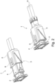
- Figure 1 shows a plug connection 1 in the not yet connected state of connector 2 (pin strip) and mating connector 3 (with housing). It can be seen that a pull-in aid geometry and a locking geometry are present on the connector 1. These geometries work together with a pull-in aid on the housing that can be moved in the direction of plugging in and a locking element that interacts with it.
- the mating connector 3 is formed by an inner housing 4 and an outer housing 5. These two parts are mounted concentrically in one another and can be moved axially relative to one another.
- a pull-in geometry 6 is arranged on the connector 2, which interacts with a pull-in lever 7 that is arranged on the mating connector 3, in particular its inner housing 4.
- the mating connector 3, in particular its outer housing 5, has an elongated guide geometry 8 that interacts with the pull-in lever 7.
- the mating connector 3, in particular its outer housing 5, can, but does not have to, have a latching hook 9 and the connector 2 has an elevation 10.
- FIG. 2 The left illustration shows a pre-insertion position in which the mating connector 3 has been inserted a little way into the connector 2. Only when the pre-insertion position is reached can the housing's pull-in aid be moved in the direction of insertion. To do this, the locking hook 9 is released by the pin strip (connector 2) at this position. This locking hook 9, which interacts with the elevation 10 of the connector 2, can be present, but does not have to be.
- FIG. 2 right illustration, the finally assembled plug connection 1 (final plug position) is shown.
- the housing's pull-in aid snaps into the housing using the locking hook.
- the elongated pull-in aid with the associated locking element is inserted into the pull-in aid geometry, guided there and then, when the final plug position is reached, fixed in the locking geometry.
- the guide geometry 6 is formed by two parallel webs 12, 13, which have a cross web 14 at one end, which forms a stop. Opposite this end, the guide geometry 6 is open so that an element of the insertion aid, which is arranged on the mating connector 3, can be inserted into a guide groove 15 formed by the two webs 12, 13 and is guided in a targeted manner during the plugging process.
- the mating connector 3 has an elongated guide groove 16, which in this embodiment is arranged in the outer housing 5.
- Further elements of the insertion aid on the side of the mating connector 3 are the insertion lever 7, which is mounted so as to be rotatable about a pivot point 17 on the mating connector 3, in particular its inner housing 4.
- the insertion aid 7 has a pin 18, 19 at each of its two ends.
- the insertion lever 7 has an angled portion 20 in its axial course, which is guided through a recess 21 in the mating connector 3, in particular its inner housing 4.
- the elevation 10 on the plug connector 2 and the locking hook 9 (in particular on the outer housing 5) as well as a recess 22, in particular on the inner housing 4, can, but do not have to, play a role.
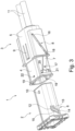
- FIG 3 is, analogous to the Figure 1 , it is shown that the individual elements of the plug connection 1 are prepared for the assembly process.
- the plug connector 2 is not yet plugged into the mating plug connector 3.
- the inner housing 4 and the outer housing 5 of the mating plug connector 3 are pulled apart so that the outer housing 5 is fixed in position on the inner housing 4, but the outer housing 5 can be pushed together further axially relative to the inner housing 4. This means that when pushed together, the inner housing 4 is almost completely immersed concentrically into the outer housing 5 of the mating plug connector 3.
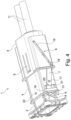
- Figure 4 shows analogous to the Figure 2 the so-called pre-insertion position.
- the connector 2 has been inserted into the inner housing 4 a little way, for which purpose an elongated axial recess (in the form of a groove) is provided on the inside of the inner housing 4, which enables the elevation 10 not to hinder the insertion of the connector 2 into the inner housing 4.
- the pin 19 of the feed lever 7 comes into the free area of the guide geometry 6.
- the outer housing 5 of the mating connector 3 is axially displaced by manual actuation over the inner housing 4, so that the pull-in aid is actuated by means of the pull-in lever 7 and the corresponding interaction of its pins 18, 19 with the guide geometry 6 on the one hand and the guide geometry 8 on the other hand.
- the pin 18 of the pull-in lever 7 slides along the obliquely arranged elongated recess 16 in the outer housing 5.
- the retraction lever 7 By immersing the inner housing 4 in the outer housing 5 due to an external manual actuation, the retraction lever 7 is pivoted about its pivot point 17, whereby the pin 18 simultaneously runs from one end position to the other in the elongated recess 16 in the outer housing 5 and also simultaneously the further pin 19 runs in the guide groove 15 of the guide geometry 6 from its introduction area to the end area.
- the free end of the locking hook 9 is lifted by the elevation 10 of the connector 2, so that the connector 2 can initially be inserted a little further into the inner housing 4, so that the pin 19 can be inserted into the straight insertion area of the guide geometry 6, which runs parallel to the longitudinal axis of the connector 2.
- the insertion aid has no effect.
- the insertion aid is only activated by subsequently pushing the outer housing 5 over the inner housing 4 by external manual operation, starting from this pre-inserted position. If the Figure 5 shown final plug position is reached, the free end of the locking hook 9, which was previously raised by the elevation 10 of the connector 2, enters a recess 22 on the top of the inner housing 4. This locking connection secures the position of the outer housing 5 on the inner housing 4 in this final plug position. However, it can be pulled apart again from the outside after the locking hook 9 has been raised. The processes are carried out in reverse order to those described above for plugging together.
Landscapes
- Details Of Connecting Devices For Male And Female Coupling (AREA)
Description
- Die Erfindung betrifft eine Einzugshilfe von elektrischen Steckverbindern mit einer Verschieberichtung in Steckrichtung, genauer eine Steckverbindung, die aus einem Steckverbinder und einem Gegensteckverbinder besteht, die zusammen zu der Steckverbindung zusammengesteckt werden können, mit einer Einzugshilfe, die an einem Teil des Steckverbinders angeordnet ist und mit einem weiteren Teil an dem Gegensteckverbinder zusammenwirkt, gemäß den Merkmalen des Oberbegriffes des Patentanspruches 1.
- Es sind Steckverbindungen bekannt, die aus einem Steckverbinder (auch als Stiftleiste bezeichnet) und einem Gegensteckverbinder (mit einem Gehäuse) besteht, die zusammen zu der Steckverbindung zusammengesteckt werden können. Da hierbei oftmals recht hohe Kräfte für den Steckvorgang erforderlich sind, sind schon Einzugshilfen bekannt geworden. Eine solche Einzugshilfe ist beispielsweise ein Hebel, der an einem Teil des Steckverbinders angeordnet ist und mit einem weiteren Teil an dem Gegensteckverbinder zusammenwirkt. Ein solcher Hebel lässt sich zwar gut betätigen, jedoch steht er von der Steckverbindung ab, bevor der Steckverbinder und der Gegensteckverbinder zusammengesteckt worden sind, sodass hierfür Bauraum, der oftmals nicht zur Verfügung steht, benötigt wird
- Der Erfindung liegt daher die Aufgabe zugrunde, eine Einzugshilfe für eine Steckverbindung dahingehend zu verbessern, dass weniger Bauraum beansprucht wird.
- Diese Aufgabe ist dadurch gelöst, dass der Steckverbinder und der Gegensteckverbinder eine Einzugshilfe aufweisen, wobei diese Einzugshilfe automatisch in Steckrichtung, d. h. beim Zusammenstecken von Steckverbinder und Gegensteckverbinder, betätigt wird. Die Einzugshilfe wirkt somit in axialer Steckrichtung der Steckverbindung, sodass sie so gut wie gar keinen Bauraum benötigt und außerdem automatisch beim Zusammenstecken von Steckverbinder und Gegensteckverbinder betätigt wird.
- Zur Realisierung der erfindungsgemäßen Einzugshilfe ist vorgesehen, dass der Steckverbinder eine Führungsgeometrie aufweist, wobei an dem Gegensteckverbinder ein beim Zusammenstecken betätigbarer Einzugshebel angeordnet ist und der mit der Führungsgeometrie als Einzugshilfe zusammenwirkt. Aufgrund des Zusammenwirkens des Einzugshebels an dem Gegensteckverbinder mit der Führungsgeometrie des Steckverbinders wird bei axialer Betätigung des Gegensteckverbinders in Richtung des Steckverbinders (oder umgekehrt) die Einzugshilfe betätigt. Aufgrund der Hebelwirkung des Einzugshebels reichen geringe Kräfte während des Zusammensteckens aus, um mittels der Einzugshilfe den Vorgang des Zusammensteckens zu unterstützen. Dies ist insbesondere dann von Vorteil, wenn der Steckverbinder und der zugehörige Gegensteckverbinder eine hohe Anzahl von miteinander zu verbindenden Kontaktpartnern aufweist. Außerdem ist es in diesem Fall nicht erforderlich, den Reibschluss zwischen Steckverbinder und Gegensteckverbinder zu optimieren, da die Reibungskräfte aufgrund der hebelartigen Vergrößerung beim Betätigen der Einzugshilfe nur noch eine untergeordnete Rolle spielen. Der Gegensteckverbinder wird dabei von einem Innengehäuse und einem axial dazu verschiebbaren Außengehäuse gebildet. Durch den axialen Schiebevorgang des Außengehäuses relativ zu dem Innengehäuse wird die Betätigung der Einzugshilfe ausgeführt. Weitere Hebel oder dergleichen, die im Stand der Technik außerhalb des Gegensteckverbinders als Einzugshilfe angeordnet sind, können entfallen, sodass durch den konzentrischen Aufbau des Gegensteckverbinders eine axiale Einzugshilfe realisiert ist, wodurch wesentlich Bauraum gespart wird.
- In der Erfindung ist vorgesehen, dass die Führungsgeometrie zwei parallel verlaufende und eine Führungsnut bildende Stege aufweist. In die Führungsnut wird ein am Ende des Einzugshebels angeordneter Zapfen eingeführt und gezielt während des Vorganges des Zusammensteckens geführt. Mittels der Führungsgeometrie und des Verlaufes der Führungsnut, die durch die beiden parallel verlaufenden Stege gebildet wird, wird Kami die Hebelwirkung des Einzugshebels gezielt beeinflusst.
- Eine gezielte Beeinflussung der Hebelwirkung des Einzugshebels erfolgt in der Erfindung dadurch, dass die beiden Stege in ihrem einen Endbereich einen sie verbindenden Quersteg aufweisen. Durch den Quersteg wird somit ein Endanschlag für die Bewegung des Zapfens des Einzugshebels, welcher Zapfen in der Führungsnut läuft, realisiert. Damit ist ein Anschlag für die Bewegung der Einzugshilfe gegeben.
- Weiterhin ist eine gezielte Beeinflussung der Hebelwirkung des Einzugshebels während der Betätigung der Einzugshilfe in Weiterbildung der Erfindung dadurch realisiert, dass die beiden parallel verlaufenden Stege in ihrem Verlauf eine Abwinklung aufweisen. Der erste Teil des Verlaufes der Stege in ihrem Einführungsbereich für den Einzugshebel bewirkt eine Aufnahme des Teiles der Einzugshilfe, die an dem Gegensteckverbinder angeordnet ist. Der weitere Verlauf der Stege bewirkt dann eine gezielte Auslenkung des Einzugshebels zusammen mit der Abwinklung in der Führungsnut, um somit die Hebelwirkung des drehbar an dem Gegensteckverbinder gelagerten Einzugshebels zu bewirken. Je nach Ausgestaltung und Bewegungsablauf der Einzugshilfe kann auch mehr als eine Abwinklung vorgesehen werden. Anstelle zumindest einer Abwinklung ist es auch denkbar, die Stege so an dem Steckverbinder zu realisieren, dass sich ein bogenförmiger Verlauf der Führungsnut ergibt.
- Zur Realisierung der Hebelwirkung der Einzugshilfe während des Zusammensteckvorganges ist in der Erfindung vorgesehen, dass der Einzugshebel über einen Drehpunkt an dem Gegensteckverbinder, insbesondere dessen Innengehäuse, angeordnet ist und in seinen beiden Endbereichen jeweils einen Zapfen aufweist. Durch die Anordnung des Einzugshebels über einen Drehpunkt an dem Gegensteckverbinder wird somit die Hebelwirkung realisiert. Die beiden an seinem Ende angeordneten Zapfen stellen die Wirkverbindung einerseits zu dem Gegensteckverbinder und andererseits zu dem Steckverbinder her.
- Weitere Ausgestaltungen und Details der erfindungsgemäßen Einzugshilfe sind in den Unteransprüchen angegeben, aus denen sich für die konstruktive Realisierung der Einzugshilfe und deren Betätigung entsprechende Vorteile ergeben. Diese weiteren Ausgestaltungen werden außerdem im Zusammenhang mit der Beschreibung der Figuren näher erläutert.
- Eine erfindungsgemäße Einzugshilfe ist in den
Figuren 1 bis 5 dargestellt. -
Figur 1 zeigt eine Steckverbindung 1 im noch nicht zusammengesteckten Zustand von Steckverbinder 2 (Stiftleiste) und Gegensteckverbinder 3 (mit Gehäuse). Es ist erkennbar, dass an dem Steckverbinder 1 eine Einzugshilfegeometrie sowie eine Verrastgeometrie vorhanden sind. Diese Geometrien wirken zusammen mit einer in Steckrichtung verschiebbaren Einzugshilfe an dem Gehäuse und einem damit zusammenwirkenden Rastelement. - Wie ebenfalls in
Figur 1 erkennbar ist, wird der Gegensteckverbinder 3 von einem Innengehäuse 4 und einem Außengehäuse 5 gebildet. Diese beiden Teile sind konzentrisch ineinander gelagert und relativ zueinander axial verschiebbar. An dem Steckverbinder 2 ist eine Einzugsgeometrie 6 angeordnet, die mit einem Einzugshebel 7, der an dem Gegensteckverbinder 3, insbesondere dessen Innengehäuse 4, angeordnet ist, zusammenwirkt. Weiterhin weist der Gegensteckverbinder 3, insbesondere dessen Außengehäuse 5, eine längliche mit dem Einzugshebel 7 zusammenwirkende Führungsgeometrie 8 auf. - Für die Realisierung der erfindungsgemäßen Einzugshilfe kann, muss aber nicht, der Gegensteckverbinder 3, insbesondere dessen Außengehäuse 5, einen Rasthaken 9 sowie der Steckverbinder 2 eine Erhebung 10 aufweisen.
- In
Figur 1 ist sehr gut erkennbar, dass der Steckverbinder 2 noch nicht in den Gegensteckverbinder 3 eingesteckt worden ist. Außerdem ist dargestellt, dass sich das Innengehäuse 4 und das Außengehäuse 5 in ihrer ausgezogenen Position befinden, aus der es möglich ist, das Außengehäuse 5 nach links in Richtung des Innengehäuses 4 zu verschieben (bei Betrachtung derFigur 1 ), sodass das Innengehäuse 4 nahezu vollständig in das Außengehäuse 5 eintaucht. -
Figur 2 zeigt in der linken Darstellung eine Vorsteckposition, bei der der Gegensteckverbinder 3 ein Stück weit in den Steckverbinder 2 eingesetzt wurde. Erst beim Erreichen der Vorsteckposition kann die Einzugshilfe des Gehäuses in Steckrichtung verschoben werden. Hierfür wird an dieser Position der Rasthaken 9 durch die Stiftleiste (Steckverbinder 2) gelöst. Dieser Rasthaken 9, der mit der Erhebung 10 des Steckverbinders 2 zusammenwirkt, kann vorhanden sein, muss es aber nicht. - In
Figur 2 , rechte Darstellung, ist die endgültig zusammengesteckte Steckverbindung 1 (finale Steckposition) dargestellt. Beim Erreichen der finalen Steckposition rastet die Einzugshilfe des Gehäuses im Gehäuse durch den Rasthaken. Die länglich gestaltete Einzugshilfe mit dem zugehörigen Rastelement wird eingeführt in die Einzugshilfegeometrie, dort geführt und dann, wenn die finale Steckposition erreicht ist, in der Verrastgeometrie festgelegt. - Der gesamte Vorgang des Zusammensteckens von Steckverbinder 2 mit dem Gegensteckverbinder 3 und die Funktionsweise der Einzugshilfe sowie der daran beteiligten Elemente werden im Folgenden im Zusammenhang mit den
Figuren 3 bis 5 noch weiter im Detail beschrieben. Die Elemente der Steckverbindung 1, wie sie in denFiguren 1 und2 dargestellt sind, sind auch in denFiguren 3 bis 5 gezeigt. - Der vorstehend beschriebene Vorgang ist selbstverständlich beim Auseinanderstecken umkehrbar
DieFiguren 3 bis 5 zeigen die beteiligten Bauelemente der Steckverbindung 1 und den Bewegungsablauf noch einmal im Detail. - In
Figur 3 ist erkennbar, dass die Führungsgeometrie 6 gebildet ist von zwei parallel verlaufenden Stegen 12, 13, die an ihrem einen Ende einen Quersteg 14 aufweisen, der einen Anschlag bildet. Diesem Ende gegenüberliegend ist die Führungsgeometrie 6 offen, damit ein Element der Einzugshilfe, welches an dem Gegensteckverbinder 3 angeordnet ist, in eine von den beiden Stegen 12, 13 gebildete Führungsnut 15 eingeführt werden kann und während des Zusammensteckvorganges gezielt geführt wird. - Für die Einzugshilfe weist der Gegensteckverbinder 3 eine längliche Führungsnut 16 auf, die bei diesem Ausführungsbeispiel in dem Außengehäuse 5 angeordnet ist. Als weitere Elemente der Einzugshilfe auf Seiten des Gegensteckverbinders 3 ist der Einzugshebel 7 vorhanden, der um einen Drehpunkt 17 herum an dem Gegensteckverbinder 3, insbesondere dessen Innengehäuse 4, drehbar gelagert ist. An seinen beiden Enden weist der Einzugshilfe 7 jeweils einen Zapfen 18, 19 auf. In einer besonderen Ausführungsform dieser Einzugshilfe weist der Einzugshebel 7 in seinem axialen Verlauf eine Abwinklung 20 auf, die durch eine Ausnehmung 21 des Gegensteckverbinders 3, insbesondere dessen Innengehäuse 4, geführt ist.
- Zur Unterstützung des Zusammensteckvorganges mit der erfindungsgemäßen Einzugshilfe können, müssen aber nicht, die Erhebung 10 an dem Steckverbinder 2 sowie der Rasthaken 9 (insbesondere an dem Außengehäuse 5) sowie eine Vertiefung 22, insbesondere an dem Innengehäuse 4, eine Rolle spielen.
- In
Figur 3 ist, analog zu derFigur 1 , gezeigt, dass die einzelnen Elemente der Steckverbindung 1 für den Zusammensteckvorgang vorbereitet sind. Dabei ist der Steckverbinder 2 noch nicht in den Gegensteckverbinder 3 eingesteckt. Innengehäuse 4 und Außengehäuse 5 des Gegensteckverbinders 3 sind auseinandergezogen, sodass eine Lagefixierung des Außengehäuses 5 auf dem Innengehäuse 4 gegeben ist, jedoch ein weiteres axiales Zusammenschieben des Außengehäuses 5 relativ zu dem Innengehäuse 4 möglich ist. Das bedeutet, dass bei diesem Zusammenschieben das Innengehäuse 4 konzentrisch nahezu vollständig in das Außengehäuses 5 des Gegensteckverbinders 3 eintaucht. - Beim Vorhandensein des Rasthakens 9 wird dieses Eintauchen noch verhindert, da ein nach innen weisendes freies Ende des Rasthakens 9, das zum Beispiel in eine nicht erkennbare Ausnehmung in der Oberfläche des Innengehäuses 4 eingreift oder das an einem stirnseitigen Ende des Innengehäuses 4 anliegt, dieses Zusammenschieben noch verhindert. Das Zusammenschieben wird erst dann ermöglicht, wenn der Steckverbinder 2 in das Innengehäuse 4 eingeführt wird und die Erhebung 10 an dem Steckverbinder 2 den Rasthaken 9, genauer dessen nach innen weisendes Ende, betätigt. Dieser Zustand ist bei der Darstellung der
Figur 3 (genauso wie bei der Darstellung derFigur 1 ) noch nicht erzielt. -
Figur 4 zeigt analog zu derFigur 2 die sogenannte Vorsteckposition. Hierzu ist der Steckverbinder 2 ein Stück weit in das Innengehäuse 4 eingesetzt worden, wozu auf der Innenseite des Innengehäuses 4 eine längliche axiale Ausnehmung (in Form einer Nut) vorhanden ist, die es ermöglicht, dass die Erhebung 10 das Eintauchen des Steckverbinders 2 in das Innengehäuse 4 nicht behindert. Wenn die Vorsteckposition gemäßFigur 4 (bzw. gemäßFigur 2 ) erreicht ist, kommt der Zapfen 19 des Einzugshebels 7 in den freien Bereich der Führungsgeometrie 6. Gleichzeitig liegt der andere Zapfen 18 des Einzugshebels 7 in dem einen Endbereich der länglichen Ausnehmung 16 der Führungsgeometrie 8 des Gegensteckverbinders 3, insbesondere dessen Außengehäuses 5. - Ausgehend von dieser Vorsteckposition wird das Außengehäuse 5 des Gegensteckverbinders 3 durch manuelle Betätigung über das Innengehäuse 4 axial verschoben, sodass mittels des Einzugshebels 7 und dem entsprechenden Zusammenwirken seiner Zapfen 18, 19 mit der Führungsgeometrie 6 einerseits und der Führungsgeometrie 8 andererseits die Einzugshilfe betätigt wird. Wenn nämlich das Außengehäuse 5 durch manuelle Betätigung von außen weiter über das Innengehäuse 4 geschoben wird (das bedeutet, dass das Innengehäuse 4 in das Außengehäuses 5 eintaucht), gleitet der Zapfen 18 des Einzugshebels 7 entlang der schräg angeordneten länglichen Ausnehmung 16 in dem Außengehäuse 5. Aufgrund der Drehung des Einzugshebels 7 um den Drehpunkt 17 herum wird der Zapfen 19 des Einzugshebels 7 weiter in die Führungsgeometrie 6 in die Führungsnut 15 eingeführt, wo die Abwinklung (oder alternativ eine bogenförmige Gestaltung) bewirkt, dass der Steckverbinder 2 weiter in das Innengehäuse 4 des Gegensteckverbinders 3 hineingezogen wird (eintaucht), ohne dass eine weitere Kraft auf den Steckverbinder 2 für diesen Einziehvorgang erforderlich ist. Wenn dieser Vorgang beendet ist, wird die in
Figur 5 (analog dazu die inFigur 2 ) gezeigte finale Steckposition erreicht. Bei dieser finalen Steckposition befindet sich der Steckverbinder 2 an seiner bestimmungsgemäßen Sollposition innerhalb des Gegensteckverbinders 3. Das bedeutet, dass die Steckverbindung 1 komplett zusammengesteckt ist. In dieser finalen Steckposition sind aufgrund des Zusammenschiebens von Innengehäuse 4 und Außengehäuse 5 der Einzugshebel 7 um seinen Drehpunkt 17 herum verschwenkt worden und der Zapfen 18 an dem anderen Ende der länglichen Ausnehmung 16 in dem Außengehäuse 5 zur Anlage gekommen, genauso wie der weitere Zapfen 19 des Einzugshebels 7 an dem Endbereich der Führungsnut 15 im Bereich des einen Anschlages bildenden Quersteges 14 angekommen ist. - Durch das Eintauchen des Innengehäuses 4 in das Außengehäuse 5 aufgrund einer äußeren manuellen Betätigung wird somit der Einzugshebel 7 um seinen Drehpunkt 17 herum verschwenkt, wodurch gleichzeitig der Zapfen 18 von seiner einen in die andere Endposition in der länglichen Ausnehmung 16 in dem Außengehäuses 5 und ebenfalls gleichzeitig der weitere Zapfen 19 in der Führungsnut 15 der Führungsgeometrie 6 von deren Einführungsbereich bis in den Endbereich läuft.
- Ausgehend von der Vorsteckposition gemäß
Figur 4 wird von der Erhebung 10 des Steckverbinders 2 das freie Ende des Rasthakens 9 angehoben, sodass es möglich wird, dass der Steckverbinder 2 zunächst ein Stück weiter in das Innengehäuse 4 eintauchen kann, sodass der Zapfen 19 in den geraden, parallel zur Längsachse des Steckverbinders 2 verlaufenden Einführungsbereich der Führungsgeometrie 6 eintauchen kann. Solange dies der Fall ist, zeigt die Einzugshilfe noch keine Wirkung. Die Einzugshilfe wird erst dann dadurch betätigt, dass in weiterer Folge ausgehend von dieser Vorsteckposition das Außengehäuses 5 durch äußere manuelle Betätigung über das Innengehäuse 4 geschoben wird. Ist dann die inFigur 5 gezeigte finale Steckposition erreicht, taucht das freie Ende des Rasthakens 9, was vorher durch die Erhebung 10 des Steckverbinders 2 angehoben worden ist, in eine Vertiefung 22 auf der Oberseite des Innengehäuses 4 ein. Durch diese Rastverbindung wird die Lage des Außengehäuses 5 auf dem Innengehäuse 4 in dieser finalen Steckposition gesichert. Es kann aber nach einem Anheben des Rasthakens 9 von außen wieder auseinandergezogen werden. Dabei erfolgen in umgekehrter Reihenfolge die Abläufe, wie sie beim Zusammenstecken vorstehend beschrieben worden sind. -
- 1.
- Steckverbindung
- 2.
- Steckverbinder
- 3.
- Gegensteckverbinder
- 4.
- Innengehäuse
- 5.
- Außengehäuse
- 6.
- Führungsgeometrie
- 7.
- Einzugshebel
- 8.
- Führungsgeometrie
- 9.
- Rasthaken
- 10.
- Erhebung
- 11.
- Leitung
- 12.
- Steg
- 13.
- Steg
- 14.
- Quersteg
- 15.
- Führungsnut
- 16.
- Längliche Ausnehmung
- 17.
- Drehpunkt
- 18.
- Zapfen
- 19.
- Zapfen
- 20.
- Abwinklung
- 21.
- Ausnehmung
- 22.
- Vertiefung
Claims (6)
- Steckverbindung (1), die aus einem Steckverbinder (2) und einem Gegensteckverbinder (3) besteht, die zusammen zu der Steckverbindung (1) zusammengesteckt werden können, mit einer Einzugshilfe, die an einem Teil des Steckverbinders (2) angeordnet ist und mit einem weiteren Teil an dem Gegensteckverbinder (3) zusammenwirkt, der Steckverbinder (2) und der Gegensteckverbinder (3) eine Einzugshilfe aufweisen, wobei diese Einzugshilfe automatisch in Steckrichtung beim Zusammenstecken von Steckverbinder und Gegensteckverbinder axial betätigt wird, wobei der Steckverbinder (2) eine Führungsgeometrie (6) aufweist, wobei an dem von einem Innengehäuse (4) und einem axial dazu verschiebbaren Außengehäuse (5) gebildeter Gegensteckverbinder (3) ein beim Zusammenstecken betätigbarer Einzugshebel (7) angeordnet ist und der mit der Führungsgeometrie (6) als Einzugshilfe zusammenwirkt, wobei der Einzugshebel (7) über einen Drehpunkt (17) an dem Gegensteckverbinder (3), insbesondere dessen Innengehäuse (4), angeordnet ist,
dadurch gekennzeichnet, dass
der Einzugshebel (7) in seinen beiden Endbereichen jeweils einen Zapfen (18,19) aufweist, wobei die Führungsgeometrie (6) zwei parallel verlaufende und eine Führungsnut (15) bildende Stege (12, 13) aufweist und die beiden Stege (12, 13) in ihrem einen Endbereich einen sie verbindenden Quersteg (14) aufweisen. - Steckverbindung nach Anspruch 1, dadurch gekennzeichnet, dass die beiden parallel verlaufenden Stege (12, 13) " in ihrem Verlauf zumindest eine Abwinklung und/oder einen bogenförmigen Verlauf aufweisen.
- Steckverbindung nach Anspruch 2, dadurch gekennzeichnet, dass der Gegensteckverbinder (3), insbesondere dessen Außengehäuse (5), eine mit dem einen Zapfen (18) des Einzugshebels (7) zusammenwirkende längliche Ausnehmung (16) aufweist.
- Steckverbindung nach Anspruch 3, dadurch gekennzeichnet, dass der Einzugshebel (7) eine Abwinklung (20) aufweist, mit der der Einzugshebel (7) durch eine Ausnehmung (21) in dem Innengehäuse (4) des Gegensteckverbinders (3) geführt ist.
- Steckverbindung nach einem der vorhergehenden Ansprüche, dadurch gekennzeichnet, dass der Steckverbinder (2) auf seiner Oberseite eine Erhebung (10) und der Gegensteckverbinder (3), insbesondere dessen Außengehäuse (5), einen beim Zusammenstecken mit der Erhebung (10) zusammenwirkenden Rasthaken (9) aufweist.
- Steckverbindung nach einem der vorhergehenden Ansprüche, dadurch gekennzeichnet, dass der Gegensteckverbinder (3), insbesondere dessen Innengehäuse (4), auf seiner Oberseite eine beim Zusammenstecken mit dem Rasthaken zusammenwirkende Vertiefung (22) aufweist.
Applications Claiming Priority (2)
| Application Number | Priority Date | Filing Date | Title |
|---|---|---|---|
| DE102017120667 | 2017-09-07 | ||
| PCT/EP2018/074130 WO2019057519A1 (de) | 2017-09-07 | 2018-09-07 | Einzugshilfe von elektrischen steckverbindern mit verschieberichtung in steckrichtung |
Publications (2)
| Publication Number | Publication Date |
|---|---|
| EP3679633A1 EP3679633A1 (de) | 2020-07-15 |
| EP3679633B1 true EP3679633B1 (de) | 2024-06-19 |
Family
ID=63524293
Family Applications (1)
| Application Number | Title | Priority Date | Filing Date |
|---|---|---|---|
| EP18765882.8A Active EP3679633B1 (de) | 2017-09-07 | 2018-09-07 | Einzugshilfe von elektrischen steckverbindern mit verschieberichtung in steckrichtung |
Country Status (5)
| Country | Link |
|---|---|
| US (1) | US11165200B2 (de) |
| EP (1) | EP3679633B1 (de) |
| CN (1) | CN111095687B (de) |
| ES (1) | ES2983983T3 (de) |
| WO (1) | WO2019057519A1 (de) |
Families Citing this family (3)
| Publication number | Priority date | Publication date | Assignee | Title |
|---|---|---|---|---|
| JP7313185B2 (ja) * | 2019-04-30 | 2023-07-24 | タイコエレクトロニクスジャパン合同会社 | コネクタハウジング |
| EP4066331A1 (de) * | 2019-11-25 | 2022-10-05 | Hirschmann Automotive GmbH | Mit hoher kraft spielfrei vorspannbare steckverbindung |
| US11502453B2 (en) * | 2020-07-28 | 2022-11-15 | Powerhydrant Llc | Electrical connector latching mechanism |
Citations (6)
| Publication number | Priority date | Publication date | Assignee | Title |
|---|---|---|---|---|
| US6276948B1 (en) | 1999-05-31 | 2001-08-21 | Yazaki Corporation | Connector supporting mechanism |
| JP2002184518A (ja) | 2000-12-14 | 2002-06-28 | Auto Network Gijutsu Kenkyusho:Kk | 倍力機構付コネクタ及び電気接続装置 |
| US6783380B1 (en) * | 2003-06-11 | 2004-08-31 | Yazaki North America, Inc. | Low insertion force connector system |
| US20070032107A1 (en) | 2005-07-29 | 2007-02-08 | Yazaki Corporation | Pivotal lever-type connector |
| US20080076286A1 (en) * | 2006-09-27 | 2008-03-27 | Chul-Sub Lee | Connector |
| US20090117764A1 (en) | 2007-11-05 | 2009-05-07 | Shigeo Mori | Lever-Type Connector |
Family Cites Families (19)
| Publication number | Priority date | Publication date | Assignee | Title |
|---|---|---|---|---|
| JPH04160775A (ja) * | 1990-10-22 | 1992-06-04 | Yazaki Corp | 嵌合操作用カム部材付きコネクタ |
| WO1996008331A1 (de) | 1994-09-13 | 1996-03-21 | Widia Gmbh | Schneideinsatz |
| JP3748301B2 (ja) * | 1996-02-27 | 2006-02-22 | 株式会社オートネットワーク技術研究所 | コネクタの結合構造 |
| US5954528A (en) | 1996-02-27 | 1999-09-21 | Harness System Technologies Research, Ltd. | Connector connection structure |
| US5921791A (en) | 1996-04-09 | 1999-07-13 | Harness System Technologies Research, Ltd. | Connector connecting structure |
| JP2001068212A (ja) * | 1999-08-26 | 2001-03-16 | Yazaki Corp | コネクタ結合構造 |
| JP3419715B2 (ja) * | 1999-10-14 | 2003-06-23 | 株式会社オートネットワーク技術研究所 | コネクタにおけるロック機構 |
| US6217354B1 (en) * | 2000-03-20 | 2001-04-17 | Molek Incorporated | Lever type electrical connector |
| JP3726641B2 (ja) * | 2000-05-23 | 2005-12-14 | 住友電装株式会社 | レバー式コネクタ |
| JP3863739B2 (ja) * | 2001-07-16 | 2006-12-27 | 矢崎総業株式会社 | 防水式低挿入力コネクタ |
| EP2063499A3 (de) * | 2002-09-19 | 2009-11-11 | Sumitomo Wiring Systems, Ltd. | Verbinderanordnung, Verbinder, Verbinderanordnungsaufbau und Anordnungsverfahren dafür |
| JP2004192957A (ja) * | 2002-12-11 | 2004-07-08 | Auto Network Gijutsu Kenkyusho:Kk | コネクタ |
| JP2004214106A (ja) * | 2003-01-07 | 2004-07-29 | Sumitomo Wiring Syst Ltd | レバー式コネクタ |
| DE602006001022T2 (de) * | 2005-04-05 | 2009-05-20 | Sumitomo Wiring Systems, Ltd., Yokkaichi | Verbinderanordnung |
| US7066763B1 (en) * | 2005-05-17 | 2006-06-27 | Sumitomo Wiring Systems, Ltd. | Junction box assembly with cam levers |
| US8011938B2 (en) * | 2008-05-21 | 2011-09-06 | Tyco Electroniccs Corporation | Electrical connector having linear actuator |
| DE102010053262B4 (de) * | 2009-12-17 | 2013-02-21 | Sumitomo Wiring Systems, Ltd. | Steckverbinder |
| JP5370254B2 (ja) | 2010-04-28 | 2013-12-18 | 住友電装株式会社 | コネクタ |
| US9325111B2 (en) * | 2012-11-30 | 2016-04-26 | Lear Corporation | Electrical center and connector assembly system |
-
2018
- 2018-09-07 CN CN201880057858.8A patent/CN111095687B/zh active Active
- 2018-09-07 US US16/634,966 patent/US11165200B2/en active Active
- 2018-09-07 ES ES18765882T patent/ES2983983T3/es active Active
- 2018-09-07 EP EP18765882.8A patent/EP3679633B1/de active Active
- 2018-09-07 WO PCT/EP2018/074130 patent/WO2019057519A1/de not_active Ceased
Patent Citations (6)
| Publication number | Priority date | Publication date | Assignee | Title |
|---|---|---|---|---|
| US6276948B1 (en) | 1999-05-31 | 2001-08-21 | Yazaki Corporation | Connector supporting mechanism |
| JP2002184518A (ja) | 2000-12-14 | 2002-06-28 | Auto Network Gijutsu Kenkyusho:Kk | 倍力機構付コネクタ及び電気接続装置 |
| US6783380B1 (en) * | 2003-06-11 | 2004-08-31 | Yazaki North America, Inc. | Low insertion force connector system |
| US20070032107A1 (en) | 2005-07-29 | 2007-02-08 | Yazaki Corporation | Pivotal lever-type connector |
| US20080076286A1 (en) * | 2006-09-27 | 2008-03-27 | Chul-Sub Lee | Connector |
| US20090117764A1 (en) | 2007-11-05 | 2009-05-07 | Shigeo Mori | Lever-Type Connector |
Also Published As
| Publication number | Publication date |
|---|---|
| EP3679633A1 (de) | 2020-07-15 |
| CN111095687A (zh) | 2020-05-01 |
| ES2983983T3 (es) | 2024-10-28 |
| WO2019057519A1 (de) | 2019-03-28 |
| US11165200B2 (en) | 2021-11-02 |
| CN111095687B (zh) | 2021-10-29 |
| US20200244007A1 (en) | 2020-07-30 |
Similar Documents
| Publication | Publication Date | Title |
|---|---|---|
| EP3491699B1 (de) | Betätiger für eine anschlusseinrichtung für elektrische leiter | |
| WO2018036898A1 (de) | Federkraftklemmanschluss | |
| DE2353004B2 (de) | Elektrischer Stecker mit Schnellverriegelung | |
| EP2395605A1 (de) | Federklemmelement und Reihenklemme | |
| WO2013004343A1 (de) | Elektrische anschlussklemme | |
| EP2852003B1 (de) | Kontaktelement für einen Steckverbinder | |
| EP3685478B1 (de) | Steckverbindung mit verriegelungsbügel mit sperre sowie verfahren zur verriegelung und entriegelung einer steckverbindung | |
| EP2680374B1 (de) | Verbindungseinrichtung | |
| DE102022118993A1 (de) | Gehäuseanordnung für einen elektrischen Stecker mit einer Steckhilfe sowie elektrischer Stecker und Steckeranordnung | |
| DE1665644C3 (de) | Elektrische Steckvorrichtung | |
| EP3261183A1 (de) | Federkontakt | |
| EP3679633A1 (de) | Einzugshilfe von elektrischen steckverbindern mit verschieberichtung in steckrichtung | |
| DE202014010621U1 (de) | Steckverbinder | |
| DE102006054647A1 (de) | Elektrische Steckverbinderkupplung | |
| EP3096410B1 (de) | Steckverbinder mit riegel zur sekundärverriegelung von kontaktpartnern | |
| DE202012102801U1 (de) | Steckverbindung zum gesicherten Verbinden von Leitungssystemen | |
| EP2006550A1 (de) | Verbindungsvorrichtung | |
| EP2713450B1 (de) | Steckverbindung und Verfahren zum Betreiben einer solchen Steckverbindung | |
| EP4066318B1 (de) | Anschlussklemme sowie elektronisches gerät | |
| EP3038213A1 (de) | Leiteranschlussklemme zum anklemmen wenigstens eines elektrischen leiters | |
| EP3408898B1 (de) | Elektrische steckverbindung | |
| EP2822106A1 (de) | Steckverbindung für Achse mit 360 Grad Steckbarkeit | |
| DE102019106352B4 (de) | Leiteranschlussklemme mit einem Betätigungselement umfassend ein Mitnehmerelement | |
| EP3790121A1 (de) | Steckverbinder und stecksystem | |
| DE202011000739U1 (de) | Steckverbindungsanordnung für elektrische Leiter |
Legal Events
| Date | Code | Title | Description |
|---|---|---|---|
| STAA | Information on the status of an ep patent application or granted ep patent |
Free format text: STATUS: UNKNOWN |
|
| STAA | Information on the status of an ep patent application or granted ep patent |
Free format text: STATUS: THE INTERNATIONAL PUBLICATION HAS BEEN MADE |
|
| PUAI | Public reference made under article 153(3) epc to a published international application that has entered the european phase |
Free format text: ORIGINAL CODE: 0009012 |
|
| STAA | Information on the status of an ep patent application or granted ep patent |
Free format text: STATUS: REQUEST FOR EXAMINATION WAS MADE |
|
| 17P | Request for examination filed |
Effective date: 20200214 |
|
| AK | Designated contracting states |
Kind code of ref document: A1 Designated state(s): AL AT BE BG CH CY CZ DE DK EE ES FI FR GB GR HR HU IE IS IT LI LT LU LV MC MK MT NL NO PL PT RO RS SE SI SK SM TR |
|
| AX | Request for extension of the european patent |
Extension state: BA ME |
|
| DAV | Request for validation of the european patent (deleted) | ||
| DAX | Request for extension of the european patent (deleted) | ||
| STAA | Information on the status of an ep patent application or granted ep patent |
Free format text: STATUS: EXAMINATION IS IN PROGRESS |
|
| 17Q | First examination report despatched |
Effective date: 20211223 |
|
| GRAP | Despatch of communication of intention to grant a patent |
Free format text: ORIGINAL CODE: EPIDOSNIGR1 |
|
| STAA | Information on the status of an ep patent application or granted ep patent |
Free format text: STATUS: GRANT OF PATENT IS INTENDED |
|
| INTG | Intention to grant announced |
Effective date: 20240228 |
|
| GRAS | Grant fee paid |
Free format text: ORIGINAL CODE: EPIDOSNIGR3 |
|
| GRAA | (expected) grant |
Free format text: ORIGINAL CODE: 0009210 |
|
| STAA | Information on the status of an ep patent application or granted ep patent |
Free format text: STATUS: THE PATENT HAS BEEN GRANTED |
|
| AK | Designated contracting states |
Kind code of ref document: B1 Designated state(s): AL AT BE BG CH CY CZ DE DK EE ES FI FR GB GR HR HU IE IS IT LI LT LU LV MC MK MT NL NO PL PT RO RS SE SI SK SM TR |
|
| REG | Reference to a national code |
Ref country code: GB Ref legal event code: FG4D Free format text: NOT ENGLISH |
|
| REG | Reference to a national code |
Ref country code: CH Ref legal event code: EP |
|
| REG | Reference to a national code |
Ref country code: DE Ref legal event code: R096 Ref document number: 502018014756 Country of ref document: DE |
|
| PG25 | Lapsed in a contracting state [announced via postgrant information from national office to epo] |
Ref country code: BG Free format text: LAPSE BECAUSE OF FAILURE TO SUBMIT A TRANSLATION OF THE DESCRIPTION OR TO PAY THE FEE WITHIN THE PRESCRIBED TIME-LIMIT Effective date: 20240619 |
|
| PG25 | Lapsed in a contracting state [announced via postgrant information from national office to epo] |
Ref country code: FI Free format text: LAPSE BECAUSE OF FAILURE TO SUBMIT A TRANSLATION OF THE DESCRIPTION OR TO PAY THE FEE WITHIN THE PRESCRIBED TIME-LIMIT Effective date: 20240619 Ref country code: HR Free format text: LAPSE BECAUSE OF FAILURE TO SUBMIT A TRANSLATION OF THE DESCRIPTION OR TO PAY THE FEE WITHIN THE PRESCRIBED TIME-LIMIT Effective date: 20240619 |
|
| REG | Reference to a national code |
Ref country code: LT Ref legal event code: MG9D |
|
| PG25 | Lapsed in a contracting state [announced via postgrant information from national office to epo] |
Ref country code: GR Free format text: LAPSE BECAUSE OF FAILURE TO SUBMIT A TRANSLATION OF THE DESCRIPTION OR TO PAY THE FEE WITHIN THE PRESCRIBED TIME-LIMIT Effective date: 20240920 |
|
| REG | Reference to a national code |
Ref country code: NL Ref legal event code: MP Effective date: 20240619 |
|
| REG | Reference to a national code |
Ref country code: ES Ref legal event code: FG2A Ref document number: 2983983 Country of ref document: ES Kind code of ref document: T3 Effective date: 20241028 |
|
| PG25 | Lapsed in a contracting state [announced via postgrant information from national office to epo] |
Ref country code: LV Free format text: LAPSE BECAUSE OF FAILURE TO SUBMIT A TRANSLATION OF THE DESCRIPTION OR TO PAY THE FEE WITHIN THE PRESCRIBED TIME-LIMIT Effective date: 20240619 |
|
| PG25 | Lapsed in a contracting state [announced via postgrant information from national office to epo] |
Ref country code: NO Free format text: LAPSE BECAUSE OF FAILURE TO SUBMIT A TRANSLATION OF THE DESCRIPTION OR TO PAY THE FEE WITHIN THE PRESCRIBED TIME-LIMIT Effective date: 20240919 Ref country code: LV Free format text: LAPSE BECAUSE OF FAILURE TO SUBMIT A TRANSLATION OF THE DESCRIPTION OR TO PAY THE FEE WITHIN THE PRESCRIBED TIME-LIMIT Effective date: 20240619 Ref country code: HR Free format text: LAPSE BECAUSE OF FAILURE TO SUBMIT A TRANSLATION OF THE DESCRIPTION OR TO PAY THE FEE WITHIN THE PRESCRIBED TIME-LIMIT Effective date: 20240619 Ref country code: GR Free format text: LAPSE BECAUSE OF FAILURE TO SUBMIT A TRANSLATION OF THE DESCRIPTION OR TO PAY THE FEE WITHIN THE PRESCRIBED TIME-LIMIT Effective date: 20240920 Ref country code: FI Free format text: LAPSE BECAUSE OF FAILURE TO SUBMIT A TRANSLATION OF THE DESCRIPTION OR TO PAY THE FEE WITHIN THE PRESCRIBED TIME-LIMIT Effective date: 20240619 Ref country code: BG Free format text: LAPSE BECAUSE OF FAILURE TO SUBMIT A TRANSLATION OF THE DESCRIPTION OR TO PAY THE FEE WITHIN THE PRESCRIBED TIME-LIMIT Effective date: 20240619 Ref country code: RS Free format text: LAPSE BECAUSE OF FAILURE TO SUBMIT A TRANSLATION OF THE DESCRIPTION OR TO PAY THE FEE WITHIN THE PRESCRIBED TIME-LIMIT Effective date: 20240919 |
|
| PG25 | Lapsed in a contracting state [announced via postgrant information from national office to epo] |
Ref country code: NL Free format text: LAPSE BECAUSE OF FAILURE TO SUBMIT A TRANSLATION OF THE DESCRIPTION OR TO PAY THE FEE WITHIN THE PRESCRIBED TIME-LIMIT Effective date: 20240619 |
|
| PG25 | Lapsed in a contracting state [announced via postgrant information from national office to epo] |
Ref country code: NL Free format text: LAPSE BECAUSE OF FAILURE TO SUBMIT A TRANSLATION OF THE DESCRIPTION OR TO PAY THE FEE WITHIN THE PRESCRIBED TIME-LIMIT Effective date: 20240619 |
|
| PG25 | Lapsed in a contracting state [announced via postgrant information from national office to epo] |
Ref country code: PT Free format text: LAPSE BECAUSE OF FAILURE TO SUBMIT A TRANSLATION OF THE DESCRIPTION OR TO PAY THE FEE WITHIN THE PRESCRIBED TIME-LIMIT Effective date: 20241021 |
|
| PG25 | Lapsed in a contracting state [announced via postgrant information from national office to epo] |
Ref country code: PT Free format text: LAPSE BECAUSE OF FAILURE TO SUBMIT A TRANSLATION OF THE DESCRIPTION OR TO PAY THE FEE WITHIN THE PRESCRIBED TIME-LIMIT Effective date: 20241021 |
|
| PG25 | Lapsed in a contracting state [announced via postgrant information from national office to epo] |
Ref country code: PL Free format text: LAPSE BECAUSE OF FAILURE TO SUBMIT A TRANSLATION OF THE DESCRIPTION OR TO PAY THE FEE WITHIN THE PRESCRIBED TIME-LIMIT Effective date: 20240619 |
|
| PG25 | Lapsed in a contracting state [announced via postgrant information from national office to epo] |
Ref country code: EE Free format text: LAPSE BECAUSE OF FAILURE TO SUBMIT A TRANSLATION OF THE DESCRIPTION OR TO PAY THE FEE WITHIN THE PRESCRIBED TIME-LIMIT Effective date: 20240619 |
|
| PG25 | Lapsed in a contracting state [announced via postgrant information from national office to epo] |
Ref country code: IS Free format text: LAPSE BECAUSE OF FAILURE TO SUBMIT A TRANSLATION OF THE DESCRIPTION OR TO PAY THE FEE WITHIN THE PRESCRIBED TIME-LIMIT Effective date: 20241019 |
|
| PG25 | Lapsed in a contracting state [announced via postgrant information from national office to epo] |
Ref country code: CZ Free format text: LAPSE BECAUSE OF FAILURE TO SUBMIT A TRANSLATION OF THE DESCRIPTION OR TO PAY THE FEE WITHIN THE PRESCRIBED TIME-LIMIT Effective date: 20240619 |
|
| PG25 | Lapsed in a contracting state [announced via postgrant information from national office to epo] |
Ref country code: SK Free format text: LAPSE BECAUSE OF FAILURE TO SUBMIT A TRANSLATION OF THE DESCRIPTION OR TO PAY THE FEE WITHIN THE PRESCRIBED TIME-LIMIT Effective date: 20240619 |
|
| PG25 | Lapsed in a contracting state [announced via postgrant information from national office to epo] |
Ref country code: SM Free format text: LAPSE BECAUSE OF FAILURE TO SUBMIT A TRANSLATION OF THE DESCRIPTION OR TO PAY THE FEE WITHIN THE PRESCRIBED TIME-LIMIT Effective date: 20240619 |
|
| PG25 | Lapsed in a contracting state [announced via postgrant information from national office to epo] |
Ref country code: SM Free format text: LAPSE BECAUSE OF FAILURE TO SUBMIT A TRANSLATION OF THE DESCRIPTION OR TO PAY THE FEE WITHIN THE PRESCRIBED TIME-LIMIT Effective date: 20240619 Ref country code: SK Free format text: LAPSE BECAUSE OF FAILURE TO SUBMIT A TRANSLATION OF THE DESCRIPTION OR TO PAY THE FEE WITHIN THE PRESCRIBED TIME-LIMIT Effective date: 20240619 Ref country code: PL Free format text: LAPSE BECAUSE OF FAILURE TO SUBMIT A TRANSLATION OF THE DESCRIPTION OR TO PAY THE FEE WITHIN THE PRESCRIBED TIME-LIMIT Effective date: 20240619 Ref country code: IS Free format text: LAPSE BECAUSE OF FAILURE TO SUBMIT A TRANSLATION OF THE DESCRIPTION OR TO PAY THE FEE WITHIN THE PRESCRIBED TIME-LIMIT Effective date: 20241019 Ref country code: EE Free format text: LAPSE BECAUSE OF FAILURE TO SUBMIT A TRANSLATION OF THE DESCRIPTION OR TO PAY THE FEE WITHIN THE PRESCRIBED TIME-LIMIT Effective date: 20240619 Ref country code: CZ Free format text: LAPSE BECAUSE OF FAILURE TO SUBMIT A TRANSLATION OF THE DESCRIPTION OR TO PAY THE FEE WITHIN THE PRESCRIBED TIME-LIMIT Effective date: 20240619 |
|
| REG | Reference to a national code |
Ref country code: DE Ref legal event code: R026 Ref document number: 502018014756 Country of ref document: DE |
|
| PLBI | Opposition filed |
Free format text: ORIGINAL CODE: 0009260 |
|
| PLAX | Notice of opposition and request to file observation + time limit sent |
Free format text: ORIGINAL CODE: EPIDOSNOBS2 |
|
| PLAS | Information related to reply of patent proprietor to notice(s) of opposition deleted |
Free format text: ORIGINAL CODE: EPIDOSDOBS3 |
|
| PLBB | Reply of patent proprietor to notice(s) of opposition received |
Free format text: ORIGINAL CODE: EPIDOSNOBS3 |
|
| PG25 | Lapsed in a contracting state [announced via postgrant information from national office to epo] |
Ref country code: DK Free format text: LAPSE BECAUSE OF FAILURE TO SUBMIT A TRANSLATION OF THE DESCRIPTION OR TO PAY THE FEE WITHIN THE PRESCRIBED TIME-LIMIT Effective date: 20240619 Ref country code: RO Free format text: LAPSE BECAUSE OF NON-PAYMENT OF DUE FEES Effective date: 20240619 |
|
| PG25 | Lapsed in a contracting state [announced via postgrant information from national office to epo] |
Ref country code: MC Free format text: LAPSE BECAUSE OF FAILURE TO SUBMIT A TRANSLATION OF THE DESCRIPTION OR TO PAY THE FEE WITHIN THE PRESCRIBED TIME-LIMIT Effective date: 20240619 |
|
| 26 | Opposition filed |
Opponent name: TE CONNECTIVITY SOLUTIONS GMBH Effective date: 20250319 |
|
| REG | Reference to a national code |
Ref country code: CH Ref legal event code: PL |
|
| PG25 | Lapsed in a contracting state [announced via postgrant information from national office to epo] |
Ref country code: LU Free format text: LAPSE BECAUSE OF NON-PAYMENT OF DUE FEES Effective date: 20240907 |
|
| GBPC | Gb: european patent ceased through non-payment of renewal fee |
Effective date: 20240919 |
|
| PG25 | Lapsed in a contracting state [announced via postgrant information from national office to epo] |
Ref country code: GB Free format text: LAPSE BECAUSE OF NON-PAYMENT OF DUE FEES Effective date: 20240919 |
|
| REG | Reference to a national code |
Ref country code: BE Ref legal event code: MM Effective date: 20240930 |
|
| PG25 | Lapsed in a contracting state [announced via postgrant information from national office to epo] |
Ref country code: BE Free format text: LAPSE BECAUSE OF NON-PAYMENT OF DUE FEES Effective date: 20240930 Ref country code: IT Free format text: LAPSE BECAUSE OF NON-PAYMENT OF DUE FEES Effective date: 20240907 |
|
| PG25 | Lapsed in a contracting state [announced via postgrant information from national office to epo] |
Ref country code: FR Free format text: LAPSE BECAUSE OF NON-PAYMENT OF DUE FEES Effective date: 20240930 |
|
| PG25 | Lapsed in a contracting state [announced via postgrant information from national office to epo] |
Ref country code: CH Free format text: LAPSE BECAUSE OF NON-PAYMENT OF DUE FEES Effective date: 20240930 |
|
| PG25 | Lapsed in a contracting state [announced via postgrant information from national office to epo] |
Ref country code: IE Free format text: LAPSE BECAUSE OF NON-PAYMENT OF DUE FEES Effective date: 20240907 |
|
| PG25 | Lapsed in a contracting state [announced via postgrant information from national office to epo] |
Ref country code: SE Free format text: LAPSE BECAUSE OF FAILURE TO SUBMIT A TRANSLATION OF THE DESCRIPTION OR TO PAY THE FEE WITHIN THE PRESCRIBED TIME-LIMIT Effective date: 20240619 |
|
| PLBB | Reply of patent proprietor to notice(s) of opposition received |
Free format text: ORIGINAL CODE: EPIDOSNOBS3 |
|
| PGFP | Annual fee paid to national office [announced via postgrant information from national office to epo] |
Ref country code: DE Payment date: 20250919 Year of fee payment: 8 |
|
| REG | Reference to a national code |
Ref country code: ES Ref legal event code: FD2A Effective date: 20251027 |
|
| REG | Reference to a national code |
Ref country code: AT Ref legal event code: MM01 Ref document number: 1696563 Country of ref document: AT Kind code of ref document: T Effective date: 20240907 |
|
| PG25 | Lapsed in a contracting state [announced via postgrant information from national office to epo] |
Ref country code: AT Free format text: LAPSE BECAUSE OF NON-PAYMENT OF DUE FEES Effective date: 20240907 |
|
| PG25 | Lapsed in a contracting state [announced via postgrant information from national office to epo] |
Ref country code: CY Free format text: LAPSE BECAUSE OF FAILURE TO SUBMIT A TRANSLATION OF THE DESCRIPTION OR TO PAY THE FEE WITHIN THE PRESCRIBED TIME-LIMIT; INVALID AB INITIO Effective date: 20180907 |
|
| PG25 | Lapsed in a contracting state [announced via postgrant information from national office to epo] |
Ref country code: ES Free format text: LAPSE BECAUSE OF NON-PAYMENT OF DUE FEES Effective date: 20240908 |
|
| PG25 | Lapsed in a contracting state [announced via postgrant information from national office to epo] |
Ref country code: HU Free format text: LAPSE BECAUSE OF FAILURE TO SUBMIT A TRANSLATION OF THE DESCRIPTION OR TO PAY THE FEE WITHIN THE PRESCRIBED TIME-LIMIT; INVALID AB INITIO Effective date: 20180907 |
|
| PG25 | Lapsed in a contracting state [announced via postgrant information from national office to epo] |
Ref country code: TR Free format text: LAPSE BECAUSE OF FAILURE TO SUBMIT A TRANSLATION OF THE DESCRIPTION OR TO PAY THE FEE WITHIN THE PRESCRIBED TIME-LIMIT Effective date: 20240619 |
|
| PG25 | Lapsed in a contracting state [announced via postgrant information from national office to epo] |
Ref country code: SI Free format text: LAPSE BECAUSE OF FAILURE TO SUBMIT A TRANSLATION OF THE DESCRIPTION OR TO PAY THE FEE WITHIN THE PRESCRIBED TIME-LIMIT Effective date: 20240619 |
|
| PG25 | Lapsed in a contracting state [announced via postgrant information from national office to epo] |
Ref country code: LT Free format text: LAPSE BECAUSE OF FAILURE TO SUBMIT A TRANSLATION OF THE DESCRIPTION OR TO PAY THE FEE WITHIN THE PRESCRIBED TIME-LIMIT Effective date: 20240619 |