EP3678794B1 - Industrielle anlage mit einem kontaktlosen wischer - Google Patents
Industrielle anlage mit einem kontaktlosen wischer Download PDFInfo
- Publication number
- EP3678794B1 EP3678794B1 EP18759328.0A EP18759328A EP3678794B1 EP 3678794 B1 EP3678794 B1 EP 3678794B1 EP 18759328 A EP18759328 A EP 18759328A EP 3678794 B1 EP3678794 B1 EP 3678794B1
- Authority
- EP
- European Patent Office
- Prior art keywords
- liquid
- strip
- cooling
- industrial facility
- wiping system
- Prior art date
- Legal status (The legal status is an assumption and is not a legal conclusion. Google has not performed a legal analysis and makes no representation as to the accuracy of the status listed.)
- Active
Links
- 238000001816 cooling Methods 0.000 claims description 46
- 239000007788 liquid Substances 0.000 claims description 43
- 239000002184 metal Substances 0.000 claims description 33
- 238000005096 rolling process Methods 0.000 claims description 26
- 239000000314 lubricant Substances 0.000 claims description 20
- XLYOFNOQVPJJNP-UHFFFAOYSA-N water Substances O XLYOFNOQVPJJNP-UHFFFAOYSA-N 0.000 claims description 19
- 238000011084 recovery Methods 0.000 claims description 8
- 239000000110 cooling liquid Substances 0.000 claims description 7
- 239000007921 spray Substances 0.000 claims description 4
- 239000002569 water oil cream Substances 0.000 claims description 4
- 238000001035 drying Methods 0.000 claims description 3
- 239000000203 mixture Substances 0.000 claims description 3
- 239000005068 cooling lubricant Substances 0.000 claims 1
- 238000005507 spraying Methods 0.000 claims 1
- 239000002826 coolant Substances 0.000 description 14
- 238000005461 lubrication Methods 0.000 description 12
- 238000009434 installation Methods 0.000 description 8
- 238000000034 method Methods 0.000 description 8
- 238000005097 cold rolling Methods 0.000 description 7
- 238000007790 scraping Methods 0.000 description 7
- 239000000839 emulsion Substances 0.000 description 6
- 238000005098 hot rolling Methods 0.000 description 6
- 238000007789 sealing Methods 0.000 description 4
- 239000011324 bead Substances 0.000 description 3
- 239000000565 sealant Substances 0.000 description 3
- 238000000926 separation method Methods 0.000 description 3
- 238000011144 upstream manufacturing Methods 0.000 description 3
- 239000000498 cooling water Substances 0.000 description 2
- 235000021183 entrée Nutrition 0.000 description 2
- 230000002093 peripheral effect Effects 0.000 description 2
- 239000003507 refrigerant Substances 0.000 description 2
- 229910000831 Steel Inorganic materials 0.000 description 1
- 241001080024 Telles Species 0.000 description 1
- 230000015572 biosynthetic process Effects 0.000 description 1
- 238000004140 cleaning Methods 0.000 description 1
- 239000011248 coating agent Substances 0.000 description 1
- 238000000576 coating method Methods 0.000 description 1
- 238000006073 displacement reaction Methods 0.000 description 1
- 230000000694 effects Effects 0.000 description 1
- 230000004907 flux Effects 0.000 description 1
- 230000003993 interaction Effects 0.000 description 1
- 238000003475 lamination Methods 0.000 description 1
- 238000012423 maintenance Methods 0.000 description 1
- 238000005259 measurement Methods 0.000 description 1
- 238000001556 precipitation Methods 0.000 description 1
- 238000003825 pressing Methods 0.000 description 1
- 238000007761 roller coating Methods 0.000 description 1
- 239000003566 sealing material Substances 0.000 description 1
- 239000010959 steel Substances 0.000 description 1
- 230000008016 vaporization Effects 0.000 description 1
Images


Classifications
-
- B—PERFORMING OPERATIONS; TRANSPORTING
- B21—MECHANICAL METAL-WORKING WITHOUT ESSENTIALLY REMOVING MATERIAL; PUNCHING METAL
- B21B—ROLLING OF METAL
- B21B45/00—Devices for surface or other treatment of work, specially combined with or arranged in, or specially adapted for use in connection with, metal-rolling mills
- B21B45/02—Devices for surface or other treatment of work, specially combined with or arranged in, or specially adapted for use in connection with, metal-rolling mills for lubricating, cooling, or cleaning
- B21B45/0269—Cleaning
- B21B45/0275—Cleaning devices
- B21B45/0278—Cleaning devices removing liquids
- B21B45/0281—Cleaning devices removing liquids removing coolants
-
- B—PERFORMING OPERATIONS; TRANSPORTING
- B21—MECHANICAL METAL-WORKING WITHOUT ESSENTIALLY REMOVING MATERIAL; PUNCHING METAL
- B21B—ROLLING OF METAL
- B21B45/00—Devices for surface or other treatment of work, specially combined with or arranged in, or specially adapted for use in connection with, metal-rolling mills
- B21B45/02—Devices for surface or other treatment of work, specially combined with or arranged in, or specially adapted for use in connection with, metal-rolling mills for lubricating, cooling, or cleaning
- B21B45/0269—Cleaning
- B21B45/0275—Cleaning devices
- B21B45/0278—Cleaning devices removing liquids
- B21B45/0284—Cleaning devices removing liquids removing lubricants
-
- B—PERFORMING OPERATIONS; TRANSPORTING
- B21—MECHANICAL METAL-WORKING WITHOUT ESSENTIALLY REMOVING MATERIAL; PUNCHING METAL
- B21B—ROLLING OF METAL
- B21B27/00—Rolls, roll alloys or roll fabrication; Lubricating, cooling or heating rolls while in use
- B21B27/06—Lubricating, cooling or heating rolls
- B21B27/10—Lubricating, cooling or heating rolls externally
- B21B2027/103—Lubricating, cooling or heating rolls externally cooling externally
-
- B—PERFORMING OPERATIONS; TRANSPORTING
- B21—MECHANICAL METAL-WORKING WITHOUT ESSENTIALLY REMOVING MATERIAL; PUNCHING METAL
- B21B—ROLLING OF METAL
- B21B45/00—Devices for surface or other treatment of work, specially combined with or arranged in, or specially adapted for use in connection with, metal-rolling mills
- B21B45/02—Devices for surface or other treatment of work, specially combined with or arranged in, or specially adapted for use in connection with, metal-rolling mills for lubricating, cooling, or cleaning
- B21B45/0269—Cleaning
- B21B45/029—Liquid recovering devices
Definitions
- the present invention relates to a wiper or scraper and generally to equipment for removing liquid from the surface of a roll or web, without mechanical contact with the roll or web, for use in the process. field of hot or cold rolling of metallurgical products, such as steel strips, without the invention being limited to such products or such uses.
- the invention also relates to an industrial installation such as a rolling mill comprising a moving metal strip and / or at least one working roll as well as a contactless wiping system as defined above.
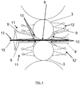
- the figure 1 schematically shows the combination of lubrication and cooling by water-oil emulsion in a cold rolling mill stand according to the state of the art, both at the inlet and at the outlet of the stand. It can be seen that the presence of traditional scrapers with contact causes the water or emulsion to leak towards the belt or the grip and this water or emulsion comes to mix with the lubricant which is projected. on the belt upstream of the cage and which is driven by the belt, making lubrication less effective and may prevent proper plate-out.
- the document WO 2008/149195 A1 discloses a rolling mill for metal products comprising at least one pair of working rollers and at least one cooling device projecting a plurality of cooling jets under pressure onto at least one working roll, the cooling device also comprising at least one jet of scraping between the cooling jets and the metal product to be rolled, the scraping jet being oriented in the desired flow direction at an angle re-entering perpendicular to the surface of the work roll.
- the document also discloses a rolling process using said rolling mill.
- the document US 5,737,796 A discloses a wiping system for removing liquids such as lubricants and coolants from the surface of a metal strip.
- the system includes upper and lower wiper rollers for wiping the upper and lower surfaces of the web, respectively.
- the wiper rolls each include a metal core and an elastic porous coating.
- the wiping system comprises at least one upper backing roller for said upper wiping roller and at least one lower backing roller for said lower wiping roll providing support for said wiping rollers, for the purpose of pressing said wiper rolls against respective adjacent web surfaces, resulting in the formation of a liquid bead on each surface of said web at the entry end of the wiping roll nip, to engage the rollers of respective wiping in the contact areas at the inlet ends of which are formed the oil beads pressed by said porous roller coatings.
- a suction assembly is provided to remove liquid from each bead.
- the document US 5,046,347 refers to a refrigerant containment apparatus for rolling mills in which an aqueous refrigerant liquid is vaporized on the surfaces of the upper and lower working rolls by respective upper and lower vaporizing heads, only on the outlet side of the rolling mill and which comprises an enclosure maintained at a pressure below atmospheric pressure and surrounding the upper spray head and the surfaces of the upper working cylinder and the adjacent back-up cylinder, upper and lower air retaining members extending along the sides edges of the enclosure above and below the spray head so as to define narrow free air spaces on the surfaces of the cylinders, pads connected to the ends of the retainers and rubbing against the cylinders so to keep the width of free spaces constant, as well as Sealing gaskets mounted on the cylinder supports at the ends of the rolling mill and cooperating with the enclosure with a view to closing off the interior of the enclosure.
- a slider removes coolant from the upper working roll on the inlet side of the rolling mill, while manifolds pick up and remove vaporized coolant through the ends of the roll nip on the outlet side of the rolling mill. Air is blown into the nip of the cylinders on the outlet side, in order to displace the coolant from the surface of an exiting rolled metal strip into the manifolds. Below the rolling line, a screen protects the rolled metal strip from coolant exiting the lower spray head.
- the document JP H0241710 A discloses a contactless device for ensuring a good seal against the cooling liquid on the surface of a rolling mill roll.
- Hydraulic cylinders are mounted on a guard and sealant is attached to a piston of the cylinders.
- the gap between the peripheral surface of a lamination roll and the end of the sealant is measured by a sensor.
- the end of the sealant is positioned by operating the cylinders with a directional control valve so as to set said gap in the correct seal area. Sealing is therefore carried out without contact between the sealing material and the peripheral surface of the roller.
- WO 97/11797 A1 which is considered to be the closest state of the art, discloses an industrial installation comprising a moving metal strip and / or at least one working cylinder as well as a descaling system, said descaling system comprising a cleat of separation with an integrated coolant supply terminated by a nozzle ramp intended to be placed according to the width of the metal strip or of the cylinder and separated, in use, by a determined interval with respect to the metal strip or the cylinder of work, the nozzle ramp being oriented so as to provide a jet in the form of a liquid curtain directed in a direction substantially opposite to the direction of travel of the strip or of rotation of the cylinder, as well as a liquid recovery gutter.
- the present invention aims to provide a contactless wiping solution in hot or cold rolling mills which overcomes the drawbacks of the state of the art.
- the invention aims to control the cooling process in the hot or cold rolling mill without harmful interaction with the lubrication process.
- the invention further aims to increase the efficiency of early cooling.
- a first aspect of the present invention relates to an industrial installation comprising a moving metal strip and / or at least one working cylinder as well as a contactless wiping system of a jet or stream of cooling liquid and / or at least one working cylinder. or lubricant entrained by the surface of said metal strip in displacement or of said working cylinder, said wiping system comprising a separation cleat with an integrated supply of coolant terminated by a nozzle ramp intended to be placed according to the width of the metal strip or of the cylinder and separated, in use, by a determined interval with respect to the metal strip or the working cylinder, the nozzle ramp being oriented so as to provide a jet in the form of a curtain of liquid directed in a direction substantially opposite to the direction of travel of the strip or of rotation of the cylinder as well as a liquid recovery gutter, so that in use, the liquid projected by the jets deflects the jet or stream of liquid and / or lubricant entrained by the belt or cylinder to form a combined flow of liquid or mixture of
- Another aspect of the present invention relates to a rolling mill stand for metal strips comprising at least one pair of working rollers and at least one cooling device projecting a plurality of jets under pressure on at least one of said rollers by virtue of a plurality.
- nozzles constituting a cooling ramp as well as a wiping system as described above, characterized in that the wiping system is proximal to the grip of the working rollers and in that the ramp of cooling is distal to said grip.
- the wiping system is located under the dimension of the axis of the working roll.
- the wiping system is located at the same level as the dimension of the axis of the working roll.
- Yet another aspect of the invention relates to a use of the wiping system described above, characterized in that the liquid projected by the jets of the wiping system is water or a water-oil emulsion.
- Yet another aspect of the invention relates to a use of the wiping system described above, at least partially, for the application of cooling, preferably highly turbulent early cooling.
- Yet another aspect of the invention relates to a use of the wiping system described above, either as an inlet wiper, to prevent back flow of the inlet coolant, or as an outlet wiper, to avoid that coolant drips downstream onto the belt surface.
- Yet another aspect of the invention relates to a use of the wiping system described above, in a hot strip rolling mill, as an inlet wiper.
- Yet another aspect of the invention relates to a use of the wiping system described above, for removing water from a strip surface in horizontal or vertical movement in a hot or cold strip rolling mill, for tape drying for measurement, lubricant application or cooling.
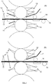
- a first embodiment of the wiping or scraping system according to the invention, applicable to a working roller, is shown in Figure figure 2 .
- the body of the wiper 7 provides the supply of coolant and is terminated by a ramp 2 preferably covering the entire width of the cylinder or of the working roller 3 and provided with a row of removable nozzles (not shown).
- the wiper 1 with its nozzle ramp 2 is separated from the working cylinder 3 by a distance or an interval 6.
- the aforementioned nozzles are directed so as to produce a jet of cooling liquid 4, in practice of water or water-oil emulsion, which opposes the jet or stream of water or emulsion 4 'applied to the cylinder as part of the conventional cooling process thereof and which is driven by this one.
- the collision of the two opposite jets 4, 4 ' causes a common deflection of the set of two jets radially outwardly of the cylinder 3.
- the common deflected jet 4 "is then collected by a gutter 5.
- FIG. 3 A second embodiment of the wiping system according to the invention, applicable to a metal strip, is shown in Figure figure 3 .
- the device is identical to that of the figure 2 , except for the presence of a flat metal strip 15 instead of the convex surface of the aforementioned working cylinder 3.
- the figure 6 shows a flow / pressure curve for a 1.3 m long wiper with 2.5 mm diameter nozzle orifices.
- the figure 7 additionally shows the calculated flow / pressure curve (nozzle orifice approx. 2 mm and 3 mm diameter resp.) and measured (orifice 2 mm). Spaced 5mm from the roller, the 2mm nozzles provide a 90% seal and the 3mm nozzles provide a near perfect seal of 95-99%. In this case, the nozzle ramp is 1.8 m long.
- an additional advantage of the water wiper according to the invention is that it makes it possible to implement early and highly turbulent cooling instead of a stationary water bath corresponding to conventional cooling of work rolls.
- the early cooling is a cooling which is generally carried out between the finishing train and the laminar cooling. It can also be carried out between the roughing train and the finishing train.
- the water scraper can replace or be combined with the conventional scrapers known in the hot rolling mill.
- conventional scrapers come into contact with the work rollers, they wear out or burn over time and coolant leaks can therefore appear at this location. This can result in inhomogeneities of the tape itself or in temperature and disruption of lubricant application.
- the equipment according to the invention can advantageously be used in the following cases.
- the invention applies to the cooling of working rolls in the hot strip rolling mill, as an inlet scraper 1 (see figure 5 ).
- an inlet scraper 1 see figure 5 .
- the invention By using a scraper according to the invention, efficient and maintenance-free sealing can be achieved such that efficient lubrication of the grip can be achieved.
- the scraper since the scraper does not come into contact with the work roll, there will be no wear of the latter.
- the invention applies to the removal of water from a horizontal or vertical strip surface in the hot or cold strip rolling mill.
- the intended purposes in this case are, for example, the drying of the tape for measuring purposes, the application of lubricant or the cooling.
Claims (13)
- Industrielle Anlage, umfassend ein Metallband in Verschiebung (15) und/oder mindestens einen Arbeitszylinder (3) sowie ein Wischsystem (1) ohne Kontakt mit einem Strahl oder Strom von Kühlflüssigkeit und/oder Schmiermittel, das durch die Fläche des Metallbands (15) oder des Arbeitszylinders (3) mitgenommen wird, wobei das Wischsystem einen Trennkeil (7) mit einer integrierten Versorgung von Kühlflüssigkeit umfasst, die durch eine Düsenrampe (2) abgeschlossen ist, die ausgelegt ist, um gemäß der Länge des Metallbands (15) oder des Zylinders (3) platziert und bei Verwendung um ein bestimmtes Intervall (6) mit Bezug auf das Metallband (15) oder den Zylinder (3) getrennt zu werden, wobei die Düsenrampe (2) derart ausgerichtet ist, dass sie einen Strahl (4) in Form eines Flüssigkeitsvorhangs abgibt, der in eine Richtung ausgerichtet ist, die im Wesentlichen der Richtung des Laufs des Bands (15) oder der Rotation des Zylinders (3) entgegengesetzt ist, sowie eine Rinne zur Wiedergewinnung von Flüssigkeit (5), sodass, bei Verwendung, die von den Düsen projizierte Flüssigkeit (2) den Strahl oder die Strömung von Flüssigkeit und/oder Schmierstoff (4') ableitet, der vom Band (15) oder vom Zylinder (3) mitgenommen wird, um einen kombinierten Fluss (4") von Flüssigkeit oder einer Mischung von Flüssigkeit und Schmierstoff oder einer Mischung von Flüssigkeit und Schmierstoff zu bilden, die sich vom Band (15) oder von der Rolle (3) entfernt, um in die Rinne zur Wiedergewinnung (5) zurückzufallen und den Ablauf des kombinierten Flusses (4") zu ermöglichen, ohne dass praktisch irgendeine Flüssigkeit und/oder irgendein Schmierstoff vom Band (15) oder vom Zylinder (3) nachgelagert vom Wischsystem (1) mitgenommen wird, wobei das Trennintervall (6) zwischen 3 und 10 mm liegt, wobei der Durchsatz der von den Düsen projizierten Flüssigkeit (2) im Bereich zwischen 10 und 200 m3/h liegt, und der Druck der projizierten Flüssigkeit im Bereich zwischen 0,5 und 5 Bar liegt,
- Industrielle Anlage nach Anspruch 1, dadurch gekennzeichnet, dass sie entworfen ist, um den größten Teil der Flüssigkeit und/oder des Schmiermittels, mitgenommen vom Band (15) oder vom Zylinder (3) zur Rinne zur Wiedergewinnung (5) umzuleiten, wenn die Flüssigkeit und/oder das restliche Schmiermittel von der Flüssigkeit, die von den Düsen (2) projiziert wird, abgeleitet ist.
- Industrielle Anlage nach Anspruch 1, dadurch gekennzeichnet, dass die Düsen (2) eine Ausgangsöffnung aufweisen, die einen Durchmesser im Bereich zwischen 1 und 5 mm aufweisen.
- Industrielle Anlage nach Anspruch 1, dadurch gekennzeichnet, dass die Düsen (2) derart ausgerichtet sind, dass sie eine Flüssigkeit auf die Oberfläche des Bands (15) oder des Arbeitszylinders (3) gemäß einer Richtung projizieren, die einen Winkel mit der Fläche im Bereich zwischen 0° und 45° bildet.
- Industrielle Anlage nach Anspruch 1, dadurch gekennzeichnet, dass der Durchsatz der von den Düsen (2) des Wischsystems projizierten Flüssigkeit (2) im Bereich zwischen 10 und 150 m3/h liegt.
- Industrielle Anlage nach einem der vorhergehenden Ansprüche in Form eines Walzgerüsts für Metallbänder, umfassend mindestens ein Paar Arbeitsrollen (3) und mindestens eine Kühlvorrichtung (11, 12), die eine Vielzahl von Strahlen unter Druck auf mindestens eine der Rollen (3) dank einer Vielzahl von Düsen projiziert, die eine Kühlrampe darstellt, in der das Wischsystem proximal mit Bezug auf den Einfluss (8) der Arbeitsrollen (3) ist und die Kühlrampe distal mit Bezug auf den Einfluss (8) ist.
- Industrielle Anlage in Form eines Walzgerüsts für Metallbänder nach Anspruch 6, dadurch gekennzeichnet, dass sich das Wischsystem (1) unter der Seite der Achse des Arbeitszylinders (3) befindet.
- Industrielle Anlage in Form eines Walzgerüsts für Metallbänder nach Anspruch 6, dadurch gekennzeichnet, dass sich das Wischsystem (1) auf dem gleichen Niveau wie die Achse des Arbeitszylinders (3) befindet.
- Industrielle Anlage nach einem der Ansprüche 1 bis 5, dadurch gekennzeichnet, dass die von den Düsen (2) des Wischsystems (1) projizierte Flüssigkeit Wasser oder eine Öl-Wasser-Emulsion ist.
- Industrielle Anlage nach einem der Ansprüche 1 bis 5 zum mindestens teilweisen Anwenden einer Kühlung, vorzugsweise einer hochturbulenten vorzeitigen Kühlung.
- Industrielle Anlage nach einem der Ansprüche 1 bis 5 in Form eines Kaltbandwalzwerks, wobei das Wischsystem (1) entweder als Eingangswischer verwendet wird, um einen Rückfluss der Eingangs-Kühlflüssigkeit zu vermeiden, oder als Ausgangswischer, um zu vermeiden, dass die Kühlflüssigkeit nachgelagert nicht auf die Fläche des Bands abtropft.
- Industrielle Anlage nach einem der Ansprüche 1 bis 5 in Form eines Heißbandwalzwerks, wobei das Wischsystem (1) als Eingangswischer verwendet wird.
- Industrielle Anlage nach einem der Ansprüche 1 bis 5, wobei das Wischsystem (1) verwendet wird, um Wasser einer Bandfläche in horizontaler oder vertikaler Verschiebung im Fall eines Heiß- oder Kaltbandwalzwerks im Hinblick auf das Trocknen des Bands zum Zweck des Messens, des Anwendens von Schmiermittel oder einer Kühlung zu beseitigen.
Applications Claiming Priority (2)
| Application Number | Priority Date | Filing Date | Title |
|---|---|---|---|
| BE2017/5614A BE1025125B1 (fr) | 2017-09-04 | 2017-09-04 | Essuyeur sans contact et installation industrielle comportant un tel essuyeur |
| PCT/EP2018/073263 WO2019043073A1 (fr) | 2017-09-04 | 2018-08-29 | Installation industrielle comportant un essuyeur sans contact |
Publications (2)
| Publication Number | Publication Date |
|---|---|
| EP3678794A1 EP3678794A1 (de) | 2020-07-15 |
| EP3678794B1 true EP3678794B1 (de) | 2021-09-29 |
Family
ID=59982202
Family Applications (1)
| Application Number | Title | Priority Date | Filing Date |
|---|---|---|---|
| EP18759328.0A Active EP3678794B1 (de) | 2017-09-04 | 2018-08-29 | Industrielle anlage mit einem kontaktlosen wischer |
Country Status (6)
| Country | Link |
|---|---|
| US (1) | US11331705B2 (de) |
| EP (1) | EP3678794B1 (de) |
| BE (1) | BE1025125B1 (de) |
| CA (1) | CA3074862A1 (de) |
| ES (1) | ES2899244T3 (de) |
| WO (1) | WO2019043073A1 (de) |
Family Cites Families (26)
| Publication number | Priority date | Publication date | Assignee | Title |
|---|---|---|---|---|
| US2849905A (en) * | 1955-01-21 | 1958-09-02 | United States Steel Corp | Cooling water spray head and collector trough for mill rolls |
| GB1511247A (en) * | 1974-06-11 | 1978-05-17 | Alcan Res & Dev | Method and apparatus for cooling the rolls of rolling mills |
| US4272976A (en) * | 1979-06-05 | 1981-06-16 | Mesta Machine Company | Hot strip rolling mill stand |
| US4400961A (en) * | 1981-07-15 | 1983-08-30 | Schaming Edward J | Apparatus for removing liquid coolant from metal strips in a rolling mill |
| US4691549A (en) * | 1981-12-24 | 1987-09-08 | United Engineering Rolling Mills, Inc. | Apparatus for removing liquid from a strip in a rolling mill and method thereof |
| DE3417697A1 (de) * | 1984-05-12 | 1985-11-14 | Krupp Stahl Ag, 4630 Bochum | Quarto-geruest zum kaltwalzen von metallbaendern |
| CH675974A5 (de) * | 1987-10-23 | 1990-11-30 | Lauener Eng Ag | |
| JP2653484B2 (ja) | 1988-08-02 | 1997-09-17 | 川崎製鉄株式会社 | 圧延ロール冷却液のシール方法 |
| US5046347A (en) | 1989-10-10 | 1991-09-10 | Alcan International Limited | Coolant containment apparatus for rolling mills |
| US5212975A (en) * | 1991-05-13 | 1993-05-25 | International Rolling Mill Consultants, Inc. | Method and apparatus for cooling rolling mill rolls and flat rolled products |
| JP2993827B2 (ja) * | 1992-10-02 | 1999-12-27 | 株式会社日立製作所 | 作業ロールクロス式圧延機及び圧延設備並びに圧延方法 |
| DE4422422A1 (de) * | 1994-01-08 | 1995-07-13 | Schloemann Siemag Ag | Vorrichtung zum berührungsfreien Abdichten eines Spaltes im Auslauf eines Walzgerüstes |
| DE19535789C2 (de) * | 1995-09-26 | 1997-09-11 | Hermetik Hydraulik Ab | Einrichtung zum Entzundern von Halbzeugen |
| US6286354B1 (en) * | 1996-04-03 | 2001-09-11 | Hitachi, Ltd. | Rolling mill and rolling method and rolling equipment |
| US5737796A (en) | 1996-09-11 | 1998-04-14 | T. Sendzimir, Inc. | Roll type strip wiping system |
| US7076983B2 (en) * | 2001-03-16 | 2006-07-18 | Nakayama Steel Works, Ltd. | Apparatus and method for hot rolling |
| WO2004014577A1 (ja) * | 2002-08-08 | 2004-02-19 | Jfe Steel Corporation | 熱延鋼帯の冷却装置、熱延鋼帯の製造方法および熱延鋼帯の製造ライン |
| BE1017462A3 (fr) * | 2007-02-09 | 2008-10-07 | Ct Rech Metallurgiques Asbl | Dispositif et procede de refroidissement de cylindres de laminage en regime hautement turbulent. |
| EP2014379A1 (de) | 2007-06-04 | 2009-01-14 | ArcelorMittal France | Walzwerk mit Kühlvorrichtung und Walzverfahren |
| ITMI20081162A1 (it) * | 2008-06-26 | 2009-12-27 | Danieli Off Mecc | Dispositivo per la rimozione di liquido o particelle solide da una superficie piana di un prodotto metallico |
| DE102009053073A1 (de) * | 2009-03-03 | 2010-09-09 | Sms Siemag Aktiengesellschaft | Verfahren und Kühlvorrichtung zum Kühlen der Walzen eines Walzgerüstes |
| DE102012202340A1 (de) * | 2011-12-23 | 2013-06-27 | Sms Siemag Ag | Verfahren und Vorrichtung zum Kühlen von Walzen |
| DE102012214298A1 (de) * | 2012-08-10 | 2014-02-13 | Sms Siemag Ag | Verfahren zur Reinigung und/oder Entzunderung einer Bramme oder eines Vorbandes mittels eines Zunderwäschers und Zunderwäscher |
| DE102014222530A1 (de) * | 2014-05-05 | 2015-11-05 | Sms Group Gmbh | Bandabweiser und Walzenanordnung |
| CA3009318C (en) * | 2016-03-29 | 2020-06-30 | Nippon Steel & Sumitomo Metal Corporation | Liquid removal device and liquid removal method |
| DE102016223131A1 (de) * | 2016-09-06 | 2018-03-08 | Sms Group Gmbh | Vorrichtung und Verfahren zum Aufbringen eines flüssigen Mediums auf eine Walze und/oder auf ein Walzgut und/oder zum Entfernen des flüssigen Mediums |
-
2017
- 2017-09-04 BE BE2017/5614A patent/BE1025125B1/fr not_active IP Right Cessation
-
2018
- 2018-08-29 EP EP18759328.0A patent/EP3678794B1/de active Active
- 2018-08-29 ES ES18759328T patent/ES2899244T3/es active Active
- 2018-08-29 WO PCT/EP2018/073263 patent/WO2019043073A1/fr unknown
- 2018-08-29 CA CA3074862A patent/CA3074862A1/en active Pending
- 2018-08-29 US US16/643,609 patent/US11331705B2/en active Active
Also Published As
| Publication number | Publication date |
|---|---|
| ES2899244T3 (es) | 2022-03-10 |
| US11331705B2 (en) | 2022-05-17 |
| US20200188976A1 (en) | 2020-06-18 |
| CA3074862A1 (en) | 2019-03-07 |
| EP3678794A1 (de) | 2020-07-15 |
| WO2019043073A1 (fr) | 2019-03-07 |
| BE1025125B1 (fr) | 2018-10-31 |
Similar Documents
| Publication | Publication Date | Title |
|---|---|---|
| RU2330737C1 (ru) | Способ и устройство для охлаждения и/или смазки валков, и/или прокатываемого материала | |
| US20070175255A1 (en) | Method of and rolling mill stand for cold rolling mill stand for cold rolling of metallic rolling stock in particular rolling strip with nozzles for gaseous or liquid treatment media | |
| US20150020845A1 (en) | Cleaning device and method for removing a lubricant from the rolls of a roll stand | |
| KR101351849B1 (ko) | 이중 가압식 실링장치 | |
| EP3678794B1 (de) | Industrielle anlage mit einem kontaktlosen wischer | |
| JPH08117820A (ja) | 圧延金属板端部の残液処理方法および装置 | |
| RU2375132C1 (ru) | Прокатная клеть с опорными и/или рабочими валками для прокатки листов или полос | |
| KR20180097696A (ko) | 제거될 표면층을 가진 몸체를 클리닝하기 위한 장치 및 방법. | |
| KR102125276B1 (ko) | 스트립 탈지설비 | |
| FR2915118A1 (fr) | Procede de nettoyage de cylindre de laminoir et dispositif correspondant | |
| KR101525060B1 (ko) | 압연롤의 이물 제거장치 | |
| JP3096524B2 (ja) | 圧延ロールの局部スプレーノズル装置及び局部冷却装置並びに局部冷却方法 | |
| KR101677548B1 (ko) | 코팅롤 표면 청소장치 | |
| KR101639251B1 (ko) | 링거 롤 및 이를 구비하는 이물질제거장치 | |
| US20200139416A1 (en) | Cleaning rolling stock during cold rolling of the rolling stock | |
| WO2003051550A1 (en) | Process control method and apparatus | |
| JPH06246334A (ja) | ストリップ付着油除去装置 | |
| CN105603822B (zh) | 密封刮刀 | |
| KR102017663B1 (ko) | 도금 강판 표면 보호장치 | |
| JP2012125776A (ja) | 圧延機の圧延液除去装置 | |
| JP3236808B2 (ja) | 鋼帯のワイピング装置及びワイピング方法 | |
| KR101747027B1 (ko) | 이물질 제거장치 | |
| JPH06344011A (ja) | 形鋼の潤滑圧延法および潤滑装置 | |
| JP2012011424A (ja) | 帯鋼の冷間仕上圧延方法および冷間仕上圧延装置 | |
| KR20130050414A (ko) | 도금층 제거장치 |
Legal Events
| Date | Code | Title | Description |
|---|---|---|---|
| STAA | Information on the status of an ep patent application or granted ep patent |
Free format text: STATUS: UNKNOWN |
|
| STAA | Information on the status of an ep patent application or granted ep patent |
Free format text: STATUS: THE INTERNATIONAL PUBLICATION HAS BEEN MADE |
|
| PUAI | Public reference made under article 153(3) epc to a published international application that has entered the european phase |
Free format text: ORIGINAL CODE: 0009012 |
|
| STAA | Information on the status of an ep patent application or granted ep patent |
Free format text: STATUS: REQUEST FOR EXAMINATION WAS MADE |
|
| 17P | Request for examination filed |
Effective date: 20200218 |
|
| AK | Designated contracting states |
Kind code of ref document: A1 Designated state(s): AL AT BE BG CH CY CZ DE DK EE ES FI FR GB GR HR HU IE IS IT LI LT LU LV MC MK MT NL NO PL PT RO RS SE SI SK SM TR |
|
| AX | Request for extension of the european patent |
Extension state: BA ME |
|
| DAV | Request for validation of the european patent (deleted) | ||
| DAX | Request for extension of the european patent (deleted) | ||
| GRAP | Despatch of communication of intention to grant a patent |
Free format text: ORIGINAL CODE: EPIDOSNIGR1 |
|
| STAA | Information on the status of an ep patent application or granted ep patent |
Free format text: STATUS: GRANT OF PATENT IS INTENDED |
|
| INTG | Intention to grant announced |
Effective date: 20210426 |
|
| GRAS | Grant fee paid |
Free format text: ORIGINAL CODE: EPIDOSNIGR3 |
|
| GRAA | (expected) grant |
Free format text: ORIGINAL CODE: 0009210 |
|
| STAA | Information on the status of an ep patent application or granted ep patent |
Free format text: STATUS: THE PATENT HAS BEEN GRANTED |
|
| AK | Designated contracting states |
Kind code of ref document: B1 Designated state(s): AL AT BE BG CH CY CZ DE DK EE ES FI FR GB GR HR HU IE IS IT LI LT LU LV MC MK MT NL NO PL PT RO RS SE SI SK SM TR |
|
| REG | Reference to a national code |
Ref country code: GB Ref legal event code: FG4D Free format text: NOT ENGLISH |
|
| REG | Reference to a national code |
Ref country code: CH Ref legal event code: EP Ref country code: AT Ref legal event code: REF Ref document number: 1433746 Country of ref document: AT Kind code of ref document: T Effective date: 20211015 |
|
| REG | Reference to a national code |
Ref country code: DE Ref legal event code: R096 Ref document number: 602018024330 Country of ref document: DE |
|
| REG | Reference to a national code |
Ref country code: IE Ref legal event code: FG4D Free format text: LANGUAGE OF EP DOCUMENT: FRENCH |
|
| REG | Reference to a national code |
Ref country code: LT Ref legal event code: MG9D |
|
| REG | Reference to a national code |
Ref country code: NL Ref legal event code: FP |
|
| PG25 | Lapsed in a contracting state [announced via postgrant information from national office to epo] |
Ref country code: NO Free format text: LAPSE BECAUSE OF FAILURE TO SUBMIT A TRANSLATION OF THE DESCRIPTION OR TO PAY THE FEE WITHIN THE PRESCRIBED TIME-LIMIT Effective date: 20211229 Ref country code: BG Free format text: LAPSE BECAUSE OF FAILURE TO SUBMIT A TRANSLATION OF THE DESCRIPTION OR TO PAY THE FEE WITHIN THE PRESCRIBED TIME-LIMIT Effective date: 20211229 Ref country code: LT Free format text: LAPSE BECAUSE OF FAILURE TO SUBMIT A TRANSLATION OF THE DESCRIPTION OR TO PAY THE FEE WITHIN THE PRESCRIBED TIME-LIMIT Effective date: 20210929 Ref country code: RS Free format text: LAPSE BECAUSE OF FAILURE TO SUBMIT A TRANSLATION OF THE DESCRIPTION OR TO PAY THE FEE WITHIN THE PRESCRIBED TIME-LIMIT Effective date: 20210929 Ref country code: SE Free format text: LAPSE BECAUSE OF FAILURE TO SUBMIT A TRANSLATION OF THE DESCRIPTION OR TO PAY THE FEE WITHIN THE PRESCRIBED TIME-LIMIT Effective date: 20210929 Ref country code: FI Free format text: LAPSE BECAUSE OF FAILURE TO SUBMIT A TRANSLATION OF THE DESCRIPTION OR TO PAY THE FEE WITHIN THE PRESCRIBED TIME-LIMIT Effective date: 20210929 Ref country code: HR Free format text: LAPSE BECAUSE OF FAILURE TO SUBMIT A TRANSLATION OF THE DESCRIPTION OR TO PAY THE FEE WITHIN THE PRESCRIBED TIME-LIMIT Effective date: 20210929 |
|
| REG | Reference to a national code |
Ref country code: AT Ref legal event code: MK05 Ref document number: 1433746 Country of ref document: AT Kind code of ref document: T Effective date: 20210929 |
|
| PG25 | Lapsed in a contracting state [announced via postgrant information from national office to epo] |
Ref country code: LV Free format text: LAPSE BECAUSE OF FAILURE TO SUBMIT A TRANSLATION OF THE DESCRIPTION OR TO PAY THE FEE WITHIN THE PRESCRIBED TIME-LIMIT Effective date: 20210929 Ref country code: GR Free format text: LAPSE BECAUSE OF FAILURE TO SUBMIT A TRANSLATION OF THE DESCRIPTION OR TO PAY THE FEE WITHIN THE PRESCRIBED TIME-LIMIT Effective date: 20211230 |
|
| REG | Reference to a national code |
Ref country code: ES Ref legal event code: FG2A Ref document number: 2899244 Country of ref document: ES Kind code of ref document: T3 Effective date: 20220310 |
|
| PG25 | Lapsed in a contracting state [announced via postgrant information from national office to epo] |
Ref country code: AT Free format text: LAPSE BECAUSE OF FAILURE TO SUBMIT A TRANSLATION OF THE DESCRIPTION OR TO PAY THE FEE WITHIN THE PRESCRIBED TIME-LIMIT Effective date: 20210929 |
|
| PG25 | Lapsed in a contracting state [announced via postgrant information from national office to epo] |
Ref country code: IS Free format text: LAPSE BECAUSE OF FAILURE TO SUBMIT A TRANSLATION OF THE DESCRIPTION OR TO PAY THE FEE WITHIN THE PRESCRIBED TIME-LIMIT Effective date: 20220129 Ref country code: SK Free format text: LAPSE BECAUSE OF FAILURE TO SUBMIT A TRANSLATION OF THE DESCRIPTION OR TO PAY THE FEE WITHIN THE PRESCRIBED TIME-LIMIT Effective date: 20210929 Ref country code: RO Free format text: LAPSE BECAUSE OF FAILURE TO SUBMIT A TRANSLATION OF THE DESCRIPTION OR TO PAY THE FEE WITHIN THE PRESCRIBED TIME-LIMIT Effective date: 20210929 Ref country code: PT Free format text: LAPSE BECAUSE OF FAILURE TO SUBMIT A TRANSLATION OF THE DESCRIPTION OR TO PAY THE FEE WITHIN THE PRESCRIBED TIME-LIMIT Effective date: 20220131 Ref country code: PL Free format text: LAPSE BECAUSE OF FAILURE TO SUBMIT A TRANSLATION OF THE DESCRIPTION OR TO PAY THE FEE WITHIN THE PRESCRIBED TIME-LIMIT Effective date: 20210929 Ref country code: EE Free format text: LAPSE BECAUSE OF FAILURE TO SUBMIT A TRANSLATION OF THE DESCRIPTION OR TO PAY THE FEE WITHIN THE PRESCRIBED TIME-LIMIT Effective date: 20210929 Ref country code: CZ Free format text: LAPSE BECAUSE OF FAILURE TO SUBMIT A TRANSLATION OF THE DESCRIPTION OR TO PAY THE FEE WITHIN THE PRESCRIBED TIME-LIMIT Effective date: 20210929 Ref country code: AL Free format text: LAPSE BECAUSE OF FAILURE TO SUBMIT A TRANSLATION OF THE DESCRIPTION OR TO PAY THE FEE WITHIN THE PRESCRIBED TIME-LIMIT Effective date: 20210929 |
|
| REG | Reference to a national code |
Ref country code: DE Ref legal event code: R097 Ref document number: 602018024330 Country of ref document: DE |
|
| PG25 | Lapsed in a contracting state [announced via postgrant information from national office to epo] |
Ref country code: DK Free format text: LAPSE BECAUSE OF FAILURE TO SUBMIT A TRANSLATION OF THE DESCRIPTION OR TO PAY THE FEE WITHIN THE PRESCRIBED TIME-LIMIT Effective date: 20210929 |
|
| PLBE | No opposition filed within time limit |
Free format text: ORIGINAL CODE: 0009261 |
|
| STAA | Information on the status of an ep patent application or granted ep patent |
Free format text: STATUS: NO OPPOSITION FILED WITHIN TIME LIMIT |
|
| 26N | No opposition filed |
Effective date: 20220630 |
|
| PG25 | Lapsed in a contracting state [announced via postgrant information from national office to epo] |
Ref country code: SI Free format text: LAPSE BECAUSE OF FAILURE TO SUBMIT A TRANSLATION OF THE DESCRIPTION OR TO PAY THE FEE WITHIN THE PRESCRIBED TIME-LIMIT Effective date: 20210929 |
|
| PG25 | Lapsed in a contracting state [announced via postgrant information from national office to epo] |
Ref country code: MC Free format text: LAPSE BECAUSE OF FAILURE TO SUBMIT A TRANSLATION OF THE DESCRIPTION OR TO PAY THE FEE WITHIN THE PRESCRIBED TIME-LIMIT Effective date: 20210929 |
|
| REG | Reference to a national code |
Ref country code: CH Ref legal event code: PL |
|
| PG25 | Lapsed in a contracting state [announced via postgrant information from national office to epo] |
Ref country code: LI Free format text: LAPSE BECAUSE OF NON-PAYMENT OF DUE FEES Effective date: 20220831 Ref country code: CH Free format text: LAPSE BECAUSE OF NON-PAYMENT OF DUE FEES Effective date: 20220831 |
|
| P01 | Opt-out of the competence of the unified patent court (upc) registered |
Effective date: 20230413 |
|
| PG25 | Lapsed in a contracting state [announced via postgrant information from national office to epo] |
Ref country code: IE Free format text: LAPSE BECAUSE OF NON-PAYMENT OF DUE FEES Effective date: 20220829 |
|
| PGFP | Annual fee paid to national office [announced via postgrant information from national office to epo] |
Ref country code: NL Payment date: 20230728 Year of fee payment: 6 Ref country code: LU Payment date: 20230728 Year of fee payment: 6 |
|
| PGFP | Annual fee paid to national office [announced via postgrant information from national office to epo] |
Ref country code: IT Payment date: 20230822 Year of fee payment: 6 Ref country code: GB Payment date: 20230728 Year of fee payment: 6 Ref country code: ES Payment date: 20230912 Year of fee payment: 6 |
|
| PGFP | Annual fee paid to national office [announced via postgrant information from national office to epo] |
Ref country code: FR Payment date: 20230822 Year of fee payment: 6 Ref country code: DE Payment date: 20230731 Year of fee payment: 6 Ref country code: BE Payment date: 20230728 Year of fee payment: 6 |
|
| PG25 | Lapsed in a contracting state [announced via postgrant information from national office to epo] |
Ref country code: SM Free format text: LAPSE BECAUSE OF FAILURE TO SUBMIT A TRANSLATION OF THE DESCRIPTION OR TO PAY THE FEE WITHIN THE PRESCRIBED TIME-LIMIT Effective date: 20210929 Ref country code: CY Free format text: LAPSE BECAUSE OF FAILURE TO SUBMIT A TRANSLATION OF THE DESCRIPTION OR TO PAY THE FEE WITHIN THE PRESCRIBED TIME-LIMIT Effective date: 20210929 |