EP3676123B1 - Réservoir de liquide pour un véhicule automobile et procédé de fabrication d'un réservoir de liquide - Google Patents
Réservoir de liquide pour un véhicule automobile et procédé de fabrication d'un réservoir de liquide Download PDFInfo
- Publication number
- EP3676123B1 EP3676123B1 EP18765379.5A EP18765379A EP3676123B1 EP 3676123 B1 EP3676123 B1 EP 3676123B1 EP 18765379 A EP18765379 A EP 18765379A EP 3676123 B1 EP3676123 B1 EP 3676123B1
- Authority
- EP
- European Patent Office
- Prior art keywords
- liquid container
- barrier layer
- shell
- support layer
- layer
- Prior art date
- Legal status (The legal status is an assumption and is not a legal conclusion. Google has not performed a legal analysis and makes no representation as to the accuracy of the status listed.)
- Active
Links
- 239000007788 liquid Substances 0.000 title claims description 105
- 238000004519 manufacturing process Methods 0.000 title claims description 6
- 230000004888 barrier function Effects 0.000 claims description 137
- 238000003860 storage Methods 0.000 claims description 41
- 229920003023 plastic Polymers 0.000 claims description 28
- 238000001746 injection moulding Methods 0.000 claims description 25
- 239000004033 plastic Substances 0.000 claims description 24
- 238000003466 welding Methods 0.000 claims description 11
- 238000000034 method Methods 0.000 claims description 7
- 230000000295 complement effect Effects 0.000 claims description 5
- 230000005540 biological transmission Effects 0.000 claims description 3
- 238000005304 joining Methods 0.000 claims description 2
- 239000010410 layer Substances 0.000 description 181
- 239000000446 fuel Substances 0.000 description 33
- 239000000463 material Substances 0.000 description 15
- 238000009792 diffusion process Methods 0.000 description 14
- 239000012876 carrier material Substances 0.000 description 12
- 229920001903 high density polyethylene Polymers 0.000 description 12
- 239000004700 high-density polyethylene Substances 0.000 description 12
- 229920000219 Ethylene vinyl alcohol Polymers 0.000 description 10
- 229920001684 low density polyethylene Polymers 0.000 description 9
- 239000004702 low-density polyethylene Substances 0.000 description 9
- UFRKOOWSQGXVKV-UHFFFAOYSA-N ethene;ethenol Chemical compound C=C.OC=C UFRKOOWSQGXVKV-UHFFFAOYSA-N 0.000 description 8
- 239000004715 ethylene vinyl alcohol Substances 0.000 description 8
- 239000002356 single layer Substances 0.000 description 7
- 239000002828 fuel tank Substances 0.000 description 5
- 239000004952 Polyamide Substances 0.000 description 4
- 229920002647 polyamide Polymers 0.000 description 4
- 239000002318 adhesion promoter Substances 0.000 description 3
- 230000000694 effects Effects 0.000 description 3
- 239000002991 molded plastic Substances 0.000 description 3
- 239000004696 Poly ether ether ketone Substances 0.000 description 2
- 239000003502 gasoline Substances 0.000 description 2
- 229930195733 hydrocarbon Natural products 0.000 description 2
- 150000002430 hydrocarbons Chemical class 0.000 description 2
- 238000002347 injection Methods 0.000 description 2
- 239000007924 injection Substances 0.000 description 2
- 229920002530 polyetherether ketone Polymers 0.000 description 2
- 229920006012 semi-aromatic polyamide Polymers 0.000 description 2
- 230000002522 swelling effect Effects 0.000 description 2
- 238000013022 venting Methods 0.000 description 2
- XSQUKJJJFZCRTK-UHFFFAOYSA-N Urea Chemical compound NC(N)=O XSQUKJJJFZCRTK-UHFFFAOYSA-N 0.000 description 1
- 238000005299 abrasion Methods 0.000 description 1
- 239000004202 carbamide Substances 0.000 description 1
- 238000002485 combustion reaction Methods 0.000 description 1
- 239000002131 composite material Substances 0.000 description 1
- 239000002826 coolant Substances 0.000 description 1
- 230000001419 dependent effect Effects 0.000 description 1
- 239000002283 diesel fuel Substances 0.000 description 1
- 229920001971 elastomer Polymers 0.000 description 1
- 239000000806 elastomer Substances 0.000 description 1
- 238000005538 encapsulation Methods 0.000 description 1
- 230000008020 evaporation Effects 0.000 description 1
- 238000001704 evaporation Methods 0.000 description 1
- 239000000945 filler Substances 0.000 description 1
- 239000012530 fluid Substances 0.000 description 1
- 239000004811 fluoropolymer Substances 0.000 description 1
- 229920002313 fluoropolymer Polymers 0.000 description 1
- 238000010438 heat treatment Methods 0.000 description 1
- 238000009434 installation Methods 0.000 description 1
- 238000000465 moulding Methods 0.000 description 1
- 238000010943 off-gassing Methods 0.000 description 1
- 230000000149 penetrating effect Effects 0.000 description 1
- 238000004023 plastic welding Methods 0.000 description 1
- 230000005855 radiation Effects 0.000 description 1
- 230000003014 reinforcing effect Effects 0.000 description 1
- 239000011435 rock Substances 0.000 description 1
- 239000000243 solution Substances 0.000 description 1
- 239000000126 substance Substances 0.000 description 1
- 229920002725 thermoplastic elastomer Polymers 0.000 description 1
- 230000008719 thickening Effects 0.000 description 1
Images


Classifications
-
- B—PERFORMING OPERATIONS; TRANSPORTING
- B60—VEHICLES IN GENERAL
- B60K—ARRANGEMENT OR MOUNTING OF PROPULSION UNITS OR OF TRANSMISSIONS IN VEHICLES; ARRANGEMENT OR MOUNTING OF PLURAL DIVERSE PRIME-MOVERS IN VEHICLES; AUXILIARY DRIVES FOR VEHICLES; INSTRUMENTATION OR DASHBOARDS FOR VEHICLES; ARRANGEMENTS IN CONNECTION WITH COOLING, AIR INTAKE, GAS EXHAUST OR FUEL SUPPLY OF PROPULSION UNITS IN VEHICLES
- B60K15/00—Arrangement in connection with fuel supply of combustion engines or other fuel consuming energy converters, e.g. fuel cells; Mounting or construction of fuel tanks
- B60K15/03—Fuel tanks
-
- B—PERFORMING OPERATIONS; TRANSPORTING
- B29—WORKING OF PLASTICS; WORKING OF SUBSTANCES IN A PLASTIC STATE IN GENERAL
- B29C—SHAPING OR JOINING OF PLASTICS; SHAPING OF MATERIAL IN A PLASTIC STATE, NOT OTHERWISE PROVIDED FOR; AFTER-TREATMENT OF THE SHAPED PRODUCTS, e.g. REPAIRING
- B29C45/00—Injection moulding, i.e. forcing the required volume of moulding material through a nozzle into a closed mould; Apparatus therefor
- B29C45/0053—Injection moulding, i.e. forcing the required volume of moulding material through a nozzle into a closed mould; Apparatus therefor combined with a final operation, e.g. shaping
-
- B—PERFORMING OPERATIONS; TRANSPORTING
- B29—WORKING OF PLASTICS; WORKING OF SUBSTANCES IN A PLASTIC STATE IN GENERAL
- B29C—SHAPING OR JOINING OF PLASTICS; SHAPING OF MATERIAL IN A PLASTIC STATE, NOT OTHERWISE PROVIDED FOR; AFTER-TREATMENT OF THE SHAPED PRODUCTS, e.g. REPAIRING
- B29C65/00—Joining or sealing of preformed parts, e.g. welding of plastics materials; Apparatus therefor
- B29C65/02—Joining or sealing of preformed parts, e.g. welding of plastics materials; Apparatus therefor by heating, with or without pressure
- B29C65/14—Joining or sealing of preformed parts, e.g. welding of plastics materials; Apparatus therefor by heating, with or without pressure using wave energy, i.e. electromagnetic radiation, or particle radiation
- B29C65/16—Laser beams
- B29C65/1629—Laser beams characterised by the way of heating the interface
- B29C65/1635—Laser beams characterised by the way of heating the interface at least passing through one of the parts to be joined, i.e. laser transmission welding
-
- B—PERFORMING OPERATIONS; TRANSPORTING
- B29—WORKING OF PLASTICS; WORKING OF SUBSTANCES IN A PLASTIC STATE IN GENERAL
- B29C—SHAPING OR JOINING OF PLASTICS; SHAPING OF MATERIAL IN A PLASTIC STATE, NOT OTHERWISE PROVIDED FOR; AFTER-TREATMENT OF THE SHAPED PRODUCTS, e.g. REPAIRING
- B29C65/00—Joining or sealing of preformed parts, e.g. welding of plastics materials; Apparatus therefor
- B29C65/02—Joining or sealing of preformed parts, e.g. welding of plastics materials; Apparatus therefor by heating, with or without pressure
- B29C65/14—Joining or sealing of preformed parts, e.g. welding of plastics materials; Apparatus therefor by heating, with or without pressure using wave energy, i.e. electromagnetic radiation, or particle radiation
- B29C65/16—Laser beams
- B29C65/1677—Laser beams making use of an absorber or impact modifier
- B29C65/1683—Laser beams making use of an absorber or impact modifier coated on the article
-
- B—PERFORMING OPERATIONS; TRANSPORTING
- B29—WORKING OF PLASTICS; WORKING OF SUBSTANCES IN A PLASTIC STATE IN GENERAL
- B29C—SHAPING OR JOINING OF PLASTICS; SHAPING OF MATERIAL IN A PLASTIC STATE, NOT OTHERWISE PROVIDED FOR; AFTER-TREATMENT OF THE SHAPED PRODUCTS, e.g. REPAIRING
- B29C65/00—Joining or sealing of preformed parts, e.g. welding of plastics materials; Apparatus therefor
- B29C65/78—Means for handling the parts to be joined, e.g. for making containers or hollow articles, e.g. means for handling sheets, plates, web-like materials, tubular articles, hollow articles or elements to be joined therewith; Means for discharging the joined articles from the joining apparatus
- B29C65/7802—Positioning the parts to be joined, e.g. aligning, indexing or centring
- B29C65/7805—Positioning the parts to be joined, e.g. aligning, indexing or centring the parts to be joined comprising positioning features
- B29C65/7814—Positioning the parts to be joined, e.g. aligning, indexing or centring the parts to be joined comprising positioning features in the form of inter-cooperating positioning features, e.g. tenons and mortises
-
- B—PERFORMING OPERATIONS; TRANSPORTING
- B29—WORKING OF PLASTICS; WORKING OF SUBSTANCES IN A PLASTIC STATE IN GENERAL
- B29C—SHAPING OR JOINING OF PLASTICS; SHAPING OF MATERIAL IN A PLASTIC STATE, NOT OTHERWISE PROVIDED FOR; AFTER-TREATMENT OF THE SHAPED PRODUCTS, e.g. REPAIRING
- B29C66/00—General aspects of processes or apparatus for joining preformed parts
- B29C66/50—General aspects of joining tubular articles; General aspects of joining long products, i.e. bars or profiled elements; General aspects of joining single elements to tubular articles, hollow articles or bars; General aspects of joining several hollow-preforms to form hollow or tubular articles
- B29C66/51—Joining tubular articles, profiled elements or bars; Joining single elements to tubular articles, hollow articles or bars; Joining several hollow-preforms to form hollow or tubular articles
- B29C66/54—Joining several hollow-preforms, e.g. half-shells, to form hollow articles, e.g. for making balls, containers; Joining several hollow-preforms, e.g. half-cylinders, to form tubular articles
-
- B—PERFORMING OPERATIONS; TRANSPORTING
- B29—WORKING OF PLASTICS; WORKING OF SUBSTANCES IN A PLASTIC STATE IN GENERAL
- B29C—SHAPING OR JOINING OF PLASTICS; SHAPING OF MATERIAL IN A PLASTIC STATE, NOT OTHERWISE PROVIDED FOR; AFTER-TREATMENT OF THE SHAPED PRODUCTS, e.g. REPAIRING
- B29C66/00—General aspects of processes or apparatus for joining preformed parts
- B29C66/70—General aspects of processes or apparatus for joining preformed parts characterised by the composition, physical properties or the structure of the material of the parts to be joined; Joining with non-plastics material
- B29C66/71—General aspects of processes or apparatus for joining preformed parts characterised by the composition, physical properties or the structure of the material of the parts to be joined; Joining with non-plastics material characterised by the composition of the plastics material of the parts to be joined
- B29C66/712—General aspects of processes or apparatus for joining preformed parts characterised by the composition, physical properties or the structure of the material of the parts to be joined; Joining with non-plastics material characterised by the composition of the plastics material of the parts to be joined the composition of one of the parts to be joined being different from the composition of the other part
-
- B—PERFORMING OPERATIONS; TRANSPORTING
- B29—WORKING OF PLASTICS; WORKING OF SUBSTANCES IN A PLASTIC STATE IN GENERAL
- B29C—SHAPING OR JOINING OF PLASTICS; SHAPING OF MATERIAL IN A PLASTIC STATE, NOT OTHERWISE PROVIDED FOR; AFTER-TREATMENT OF THE SHAPED PRODUCTS, e.g. REPAIRING
- B29C66/00—General aspects of processes or apparatus for joining preformed parts
- B29C66/70—General aspects of processes or apparatus for joining preformed parts characterised by the composition, physical properties or the structure of the material of the parts to be joined; Joining with non-plastics material
- B29C66/72—General aspects of processes or apparatus for joining preformed parts characterised by the composition, physical properties or the structure of the material of the parts to be joined; Joining with non-plastics material characterised by the structure of the material of the parts to be joined
- B29C66/723—General aspects of processes or apparatus for joining preformed parts characterised by the composition, physical properties or the structure of the material of the parts to be joined; Joining with non-plastics material characterised by the structure of the material of the parts to be joined being multi-layered
- B29C66/7234—General aspects of processes or apparatus for joining preformed parts characterised by the composition, physical properties or the structure of the material of the parts to be joined; Joining with non-plastics material characterised by the structure of the material of the parts to be joined being multi-layered comprising a barrier layer
-
- B—PERFORMING OPERATIONS; TRANSPORTING
- B29—WORKING OF PLASTICS; WORKING OF SUBSTANCES IN A PLASTIC STATE IN GENERAL
- B29C—SHAPING OR JOINING OF PLASTICS; SHAPING OF MATERIAL IN A PLASTIC STATE, NOT OTHERWISE PROVIDED FOR; AFTER-TREATMENT OF THE SHAPED PRODUCTS, e.g. REPAIRING
- B29C66/00—General aspects of processes or apparatus for joining preformed parts
- B29C66/70—General aspects of processes or apparatus for joining preformed parts characterised by the composition, physical properties or the structure of the material of the parts to be joined; Joining with non-plastics material
- B29C66/73—General aspects of processes or apparatus for joining preformed parts characterised by the composition, physical properties or the structure of the material of the parts to be joined; Joining with non-plastics material characterised by the intensive physical properties of the material of the parts to be joined, by the optical properties of the material of the parts to be joined, by the extensive physical properties of the parts to be joined, by the state of the material of the parts to be joined or by the material of the parts to be joined being a thermoplastic or a thermoset
- B29C66/735—General aspects of processes or apparatus for joining preformed parts characterised by the composition, physical properties or the structure of the material of the parts to be joined; Joining with non-plastics material characterised by the intensive physical properties of the material of the parts to be joined, by the optical properties of the material of the parts to be joined, by the extensive physical properties of the parts to be joined, by the state of the material of the parts to be joined or by the material of the parts to be joined being a thermoplastic or a thermoset characterised by the extensive physical properties of the parts to be joined
- B29C66/7352—Thickness, e.g. very thin
-
- B—PERFORMING OPERATIONS; TRANSPORTING
- B60—VEHICLES IN GENERAL
- B60K—ARRANGEMENT OR MOUNTING OF PROPULSION UNITS OR OF TRANSMISSIONS IN VEHICLES; ARRANGEMENT OR MOUNTING OF PLURAL DIVERSE PRIME-MOVERS IN VEHICLES; AUXILIARY DRIVES FOR VEHICLES; INSTRUMENTATION OR DASHBOARDS FOR VEHICLES; ARRANGEMENTS IN CONNECTION WITH COOLING, AIR INTAKE, GAS EXHAUST OR FUEL SUPPLY OF PROPULSION UNITS IN VEHICLES
- B60K15/00—Arrangement in connection with fuel supply of combustion engines or other fuel consuming energy converters, e.g. fuel cells; Mounting or construction of fuel tanks
- B60K15/03—Fuel tanks
- B60K15/03177—Fuel tanks made of non-metallic material, e.g. plastics, or of a combination of non-metallic and metallic material
-
- B—PERFORMING OPERATIONS; TRANSPORTING
- B29—WORKING OF PLASTICS; WORKING OF SUBSTANCES IN A PLASTIC STATE IN GENERAL
- B29C—SHAPING OR JOINING OF PLASTICS; SHAPING OF MATERIAL IN A PLASTIC STATE, NOT OTHERWISE PROVIDED FOR; AFTER-TREATMENT OF THE SHAPED PRODUCTS, e.g. REPAIRING
- B29C65/00—Joining or sealing of preformed parts, e.g. welding of plastics materials; Apparatus therefor
- B29C65/02—Joining or sealing of preformed parts, e.g. welding of plastics materials; Apparatus therefor by heating, with or without pressure
- B29C65/06—Joining or sealing of preformed parts, e.g. welding of plastics materials; Apparatus therefor by heating, with or without pressure using friction, e.g. spin welding
-
- B—PERFORMING OPERATIONS; TRANSPORTING
- B29—WORKING OF PLASTICS; WORKING OF SUBSTANCES IN A PLASTIC STATE IN GENERAL
- B29C—SHAPING OR JOINING OF PLASTICS; SHAPING OF MATERIAL IN A PLASTIC STATE, NOT OTHERWISE PROVIDED FOR; AFTER-TREATMENT OF THE SHAPED PRODUCTS, e.g. REPAIRING
- B29C65/00—Joining or sealing of preformed parts, e.g. welding of plastics materials; Apparatus therefor
- B29C65/02—Joining or sealing of preformed parts, e.g. welding of plastics materials; Apparatus therefor by heating, with or without pressure
- B29C65/08—Joining or sealing of preformed parts, e.g. welding of plastics materials; Apparatus therefor by heating, with or without pressure using ultrasonic vibrations
-
- B—PERFORMING OPERATIONS; TRANSPORTING
- B29—WORKING OF PLASTICS; WORKING OF SUBSTANCES IN A PLASTIC STATE IN GENERAL
- B29C—SHAPING OR JOINING OF PLASTICS; SHAPING OF MATERIAL IN A PLASTIC STATE, NOT OTHERWISE PROVIDED FOR; AFTER-TREATMENT OF THE SHAPED PRODUCTS, e.g. REPAIRING
- B29C65/00—Joining or sealing of preformed parts, e.g. welding of plastics materials; Apparatus therefor
- B29C65/02—Joining or sealing of preformed parts, e.g. welding of plastics materials; Apparatus therefor by heating, with or without pressure
- B29C65/10—Joining or sealing of preformed parts, e.g. welding of plastics materials; Apparatus therefor by heating, with or without pressure using hot gases (e.g. combustion gases) or flames coming in contact with at least one of the parts to be joined
-
- B—PERFORMING OPERATIONS; TRANSPORTING
- B29—WORKING OF PLASTICS; WORKING OF SUBSTANCES IN A PLASTIC STATE IN GENERAL
- B29C—SHAPING OR JOINING OF PLASTICS; SHAPING OF MATERIAL IN A PLASTIC STATE, NOT OTHERWISE PROVIDED FOR; AFTER-TREATMENT OF THE SHAPED PRODUCTS, e.g. REPAIRING
- B29C65/00—Joining or sealing of preformed parts, e.g. welding of plastics materials; Apparatus therefor
- B29C65/02—Joining or sealing of preformed parts, e.g. welding of plastics materials; Apparatus therefor by heating, with or without pressure
- B29C65/14—Joining or sealing of preformed parts, e.g. welding of plastics materials; Apparatus therefor by heating, with or without pressure using wave energy, i.e. electromagnetic radiation, or particle radiation
-
- B—PERFORMING OPERATIONS; TRANSPORTING
- B29—WORKING OF PLASTICS; WORKING OF SUBSTANCES IN A PLASTIC STATE IN GENERAL
- B29C—SHAPING OR JOINING OF PLASTICS; SHAPING OF MATERIAL IN A PLASTIC STATE, NOT OTHERWISE PROVIDED FOR; AFTER-TREATMENT OF THE SHAPED PRODUCTS, e.g. REPAIRING
- B29C66/00—General aspects of processes or apparatus for joining preformed parts
- B29C66/01—General aspects dealing with the joint area or with the area to be joined
- B29C66/05—Particular design of joint configurations
- B29C66/10—Particular design of joint configurations particular design of the joint cross-sections
- B29C66/13—Single flanged joints; Fin-type joints; Single hem joints; Edge joints; Interpenetrating fingered joints; Other specific particular designs of joint cross-sections not provided for in groups B29C66/11 - B29C66/12
- B29C66/131—Single flanged joints, i.e. one of the parts to be joined being rigid and flanged in the joint area
- B29C66/1312—Single flange to flange joints, the parts to be joined being rigid
-
- B—PERFORMING OPERATIONS; TRANSPORTING
- B29—WORKING OF PLASTICS; WORKING OF SUBSTANCES IN A PLASTIC STATE IN GENERAL
- B29C—SHAPING OR JOINING OF PLASTICS; SHAPING OF MATERIAL IN A PLASTIC STATE, NOT OTHERWISE PROVIDED FOR; AFTER-TREATMENT OF THE SHAPED PRODUCTS, e.g. REPAIRING
- B29C66/00—General aspects of processes or apparatus for joining preformed parts
- B29C66/70—General aspects of processes or apparatus for joining preformed parts characterised by the composition, physical properties or the structure of the material of the parts to be joined; Joining with non-plastics material
- B29C66/71—General aspects of processes or apparatus for joining preformed parts characterised by the composition, physical properties or the structure of the material of the parts to be joined; Joining with non-plastics material characterised by the composition of the plastics material of the parts to be joined
-
- B—PERFORMING OPERATIONS; TRANSPORTING
- B29—WORKING OF PLASTICS; WORKING OF SUBSTANCES IN A PLASTIC STATE IN GENERAL
- B29D—PRODUCING PARTICULAR ARTICLES FROM PLASTICS OR FROM SUBSTANCES IN A PLASTIC STATE
- B29D22/00—Producing hollow articles
- B29D22/003—Containers for packaging, storing or transporting, e.g. bottles, jars, cans, barrels, tanks
-
- B—PERFORMING OPERATIONS; TRANSPORTING
- B29—WORKING OF PLASTICS; WORKING OF SUBSTANCES IN A PLASTIC STATE IN GENERAL
- B29L—INDEXING SCHEME ASSOCIATED WITH SUBCLASS B29C, RELATING TO PARTICULAR ARTICLES
- B29L2031/00—Other particular articles
- B29L2031/712—Containers; Packaging elements or accessories, Packages
- B29L2031/7172—Fuel tanks, jerry cans
-
- B—PERFORMING OPERATIONS; TRANSPORTING
- B60—VEHICLES IN GENERAL
- B60K—ARRANGEMENT OR MOUNTING OF PROPULSION UNITS OR OF TRANSMISSIONS IN VEHICLES; ARRANGEMENT OR MOUNTING OF PLURAL DIVERSE PRIME-MOVERS IN VEHICLES; AUXILIARY DRIVES FOR VEHICLES; INSTRUMENTATION OR DASHBOARDS FOR VEHICLES; ARRANGEMENTS IN CONNECTION WITH COOLING, AIR INTAKE, GAS EXHAUST OR FUEL SUPPLY OF PROPULSION UNITS IN VEHICLES
- B60K15/00—Arrangement in connection with fuel supply of combustion engines or other fuel consuming energy converters, e.g. fuel cells; Mounting or construction of fuel tanks
- B60K15/03—Fuel tanks
- B60K2015/03032—Manufacturing of fuel tanks
- B60K2015/03046—Manufacturing of fuel tanks made from more than one layer
-
- B—PERFORMING OPERATIONS; TRANSPORTING
- B60—VEHICLES IN GENERAL
- B60K—ARRANGEMENT OR MOUNTING OF PROPULSION UNITS OR OF TRANSMISSIONS IN VEHICLES; ARRANGEMENT OR MOUNTING OF PLURAL DIVERSE PRIME-MOVERS IN VEHICLES; AUXILIARY DRIVES FOR VEHICLES; INSTRUMENTATION OR DASHBOARDS FOR VEHICLES; ARRANGEMENTS IN CONNECTION WITH COOLING, AIR INTAKE, GAS EXHAUST OR FUEL SUPPLY OF PROPULSION UNITS IN VEHICLES
- B60K15/00—Arrangement in connection with fuel supply of combustion engines or other fuel consuming energy converters, e.g. fuel cells; Mounting or construction of fuel tanks
- B60K15/03—Fuel tanks
- B60K2015/03032—Manufacturing of fuel tanks
- B60K2015/03059—Fuel tanks with double shells or more
-
- B—PERFORMING OPERATIONS; TRANSPORTING
- B60—VEHICLES IN GENERAL
- B60K—ARRANGEMENT OR MOUNTING OF PROPULSION UNITS OR OF TRANSMISSIONS IN VEHICLES; ARRANGEMENT OR MOUNTING OF PLURAL DIVERSE PRIME-MOVERS IN VEHICLES; AUXILIARY DRIVES FOR VEHICLES; INSTRUMENTATION OR DASHBOARDS FOR VEHICLES; ARRANGEMENTS IN CONNECTION WITH COOLING, AIR INTAKE, GAS EXHAUST OR FUEL SUPPLY OF PROPULSION UNITS IN VEHICLES
- B60K15/00—Arrangement in connection with fuel supply of combustion engines or other fuel consuming energy converters, e.g. fuel cells; Mounting or construction of fuel tanks
- B60K15/03—Fuel tanks
- B60K2015/03486—Fuel tanks characterised by the materials the tank or parts thereof are essentially made from
- B60K2015/03493—Fuel tanks characterised by the materials the tank or parts thereof are essentially made from made of plastics
Definitions
- the present invention relates to a liquid container for a motor vehicle and a method for producing a liquid container.
- a large number of operating fluids are carried in modern motor vehicles, such as fuel, urea solution for exhaust gas aftertreatment or coolant.
- the liquids are each held in a liquid container.
- plastic fuel tanks are used to store fuel.
- Such plastic fuel tanks should ideally be light, crash-proof and low in emissions.
- emissions the increasingly strict legal limit values for the maximum permissible fuel evaporation emissions of hydrocarbons into the environment must be complied with. This requires the avoidance of fuel leaks under all operating conditions, such as during refueling, including refueling venting, during operational venting, i.e. fuel outgassing when the temperature of a tank system rises, as well as the diffusion of hydrocarbons through the container wall.
- known fuel containers have a diffusion barrier on. If such a fuel tank is formed by assembling two injection-molded half-shells, an inner barrier layer can be arranged on a carrier material for each half-shell, for example.
- the disadvantage here is that any connection or shaped elements of the carrier material that are integrated in the injection molding and project into the storage volume break through the barrier layer and thus form permeation paths through which there is increased fuel emission.
- the document US2011 / 140314 describes a liquid container with a first half-shell and with a second half-shell, the half-shells delimiting a storage volume for receiving liquid, the half-shells having two carrier layers with a barrier layer in between.
- the invention is based on the technical problem of specifying a liquid container and a method for producing a liquid container which do not have the disadvantages described above, or at least to a lesser extent, and in particular enable a reduced diffusion-related emission of a liquid container.
- the first half-shell is an upper shell of a plastic fuel tank for a motor vehicle.
- the second half-shell is a lower shell of the plastic fuel tank.
- the upper shell When installed, the upper shell faces the vehicle. In the fully assembled state, the lower shell faces away from the vehicle or faces the street or lane. Due to the internal arrangement of the second barrier layer, the second barrier layer is protected from mechanical abrasion, e.g. from falling rocks, during vehicle operation.
- the upper shell can thus be used to attach attachments or molded elements on the inside, in particular to weld them on, without breaking through the first barrier layer.
- the first carrier layer has one or more shaped elements, connection parts or functional units on a side facing the storage volume.
- This can be, for example, valve holders, clips for the form-fitting and force-fitting fastening of functional units or bases for the material-fitting connection of functional units.
- the first barrier layer is arranged on a side of the first carrier layer facing away from the storage volume, the molded elements, connection parts or functional units can be arranged, sprayed or applied on the side of the first carrier layer facing the storage volume without the first barrier layer being interrupted.
- they can be formed integrally or in one piece in an injection molding process Molded elements are produced without compromising the structural integrity of the first barrier layer.
- the shaped elements, connecting parts or functional units can, for example, be elements that protrude into the storage volume.
- the molded elements and / or connection parts can have been formed in one piece with the first carrier layer in an injection molding process and / or have been injection-molded sequentially onto the first carrier layer.
- the integral connection of the molded elements and / or connection parts which takes place in one piece in the injection molding process, has the advantage that inexpensive production of the molded elements and / or connection parts is possible.
- the sequential molding on of the molded elements and / or connecting parts offers the advantage of greater freedom of design with regard to the wall thickness and position of the molded elements and / or connecting parts.
- all shaped elements, connection parts or functional units arranged in the storage volume are arranged on the first carrier layer, with no shaped elements, connection parts or functional units arranged in the storage volume being arranged on the second barrier layer. In this way, all required shaped elements, connection parts or functional units can be arranged within the liquid container without the need to break through or interrupt the first barrier layer or the second barrier layer.
- a plastic is locally injection-molded on a side of the second barrier layer facing away from the second carrier layer, which plastic is used to connect one or more shaped elements, connecting parts or functional units is used.
- a carrier material can be locally injected onto the second barrier layer by sequential injection molding on a side of the barrier layer facing away from the carrier layer.
- the locally injection-molded plastic can, for example, be a base or plate-like element made of carrier material, to which, for example, a surge pot can be welded or glued.
- a functional unit can be arranged in the area of the second half-shell with an internal barrier layer without breaking through or interrupting the second barrier layer.
- the barrier effect of the second barrier layer can thus be maintained, with molded elements, connection parts or functional units also being able to be arranged in the area of the locally molded plastic of the lower half-shell.
- At least one of the barrier layers can be a single-layer film that has been materially bonded to the assigned carrier layer in an injection molding process.
- the film can be accommodated in a tool half of an injection molding tool and injected or back-injected with plasticized carrier material.
- the injection molding process creates an integral connection between the barrier film and the carrier layer. In this way, a half-shell with a carrier layer and barrier film can be produced inexpensively and with little use of material.
- At least one of the barrier layers is a multi-layer film that has been materially bonded to the assigned carrier layer in an injection molding process.
- a multi-layer film can, for example, be a five-layer film which has a central layer made of EVOH (Ethylene-vinyl alcohol copolymer), the EVOH layer is covered on both sides by an LDPE (low-density polyethylene) layer, and the LDPE layers in turn are covered by HDPE (high-density polyethylene) layers.
- EVOH Ethylene-vinyl alcohol copolymer
- the cover layers of a multilayer film can in particular be of the same type as the carrier material in order to achieve a reliable material connection between the carrier material and the barrier film.
- the barrier effect of a multi-layer film can largely be provided by an EVOH layer, while the LDPE layers each serve as an adhesion promoter to the outer HDPE layers and the HDPE layers in turn are intended for reliable adhesion or material connection with a carrier material can be, wherein the carrier material can also consist of the HDPE of the outer layers of the barrier film.
- the liquid container can be a plastic fuel container for holding a gasoline or diesel fuel.
- the barrier layers and / or the carrier layers are particularly suitable for being in contact with a diesel or gasoline fuel.
- the material of the barrier film and the material of the carrier layer must therefore be suitable in terms of their swelling properties for being in direct contact with a liquid fuel.
- Both the carrier material and the barrier layer must be suitable for use in direct contact with fuel in terms of their chemical resistance and swelling properties.
- the single-layer or multi-layer carrier layer can have one or more of the following materials or consist of one or more of the following materials: elastomer, thermoplastic Elastomer, HDPE (high-density polyethylene), fiber-reinforced polyamide, PA (polyamide), partially aromatic polyamide, impact-resistant polyamide.
- the single or multi-layer barrier layer can have one or more of the following materials or consist of one or more of the following materials: EVOH (ethylene-vinyl alcohol copolymer), LDPE (low-density polyethylene), PEEK (polyetheretherketone), PA (polyamide), partially aromatic polyamide, HDPE (high-density polyethylene), fluoropolymer.
- the barrier layer can be made up of three layers of PA and EVOH, with a central EVOH layer being covered or bordered on two sides by PA cover layers.
- a six-layer wall structure, for example, or the five-layer structure made of HDPE, LDPE and EVOH, which has already been described above, can also be provided.
- the half-shells are materially connected to one another in a connection area, the first carrier layer in the connection area being materially connected to the second barrier layer and / or the second carrier layer, the first barrier layer and the second barrier layer in the Connection area are spaced apart from one another and border the first carrier layer on two sides, the first carrier layer in the connection area forming a permeation path between the storage volume and the surroundings of the liquid container.
- the cohesive connection of the half-shells to form a closed liquid container can be effected by a plastic welding process, in particular non-contact processes or non-contact welding processes. These include, for example, heating element welding, vibration welding, radiation welding, ultrasonic welding or hot gas welding.
- the two barrier layers thus do not form a closed barrier bubble that would essentially completely enclose the storage volume, i.e. except for the connections that are mandatory for a tank, but rather it a section of first carrier material is present in the connection area, via which there is a diffusion-effective connection between the storage volume and an environment which is not limited by the barrier films.
- a length of the permeation path is greater than or equal to twice the width of the permeation path, the width of the permeation path corresponding to the distance between the barrier layers in the connection area.
- such a permeation path should be made as long and narrow as possible in the connection area in order to keep the diffusion-related emission low.
- a length of the permeation path is greater than a wall thickness of the first half-shell and the second half-shell.
- Such a configuration can be achieved, for example, in that the permeation path runs inclined relative to a horizontal plane when viewed in the installation position of the liquid container.
- the permeation path or a connection area formed between the half-shells can run inclined or inclined in order to constructively lengthen the permeation path without significantly increasing the dimensions of the liquid container.
- first barrier layer and the second barrier layer are materially connected to one another.
- no permeation path is formed in a connection area between the half-shells and the barrier layers form an essentially closed barrier bubble which essentially completely encloses the storage volume of the liquid container, with the restriction that the connections that are mandatory for a tank, such as filler neck, vent and / or removal opening are provided. In this way, diffusion-related emission can be reliably limited.
- connection openings penetrating the wall of a half-shell can be provided.
- the connection openings can have been produced by injection molding.
- the first barrier layer essentially completely covers the side of the first carrier layer facing away from the storage volume. In this way, a reliable encapsulation of a liquid fuel that is to be stored, for example, can be achieved.
- the second barrier layer is on the side facing the storage volume substantially completely covered by the second carrier layer. This in turn serves to reliably reduce diffusion-related emissions.
- At least one of the half-shells of the liquid container has a web, the web sitting positively in an at least partially complementary shaped receptacle of the respective other half-shell, a material connection of the half-shells being formed along the web.
- the first half-shell can be provided with such a web, wherein the first half-shell can in particular form a cover for the second half-shell.
- the first and the second half-shell can be constructed asymmetrically, the second half-shell, for example, forming an upwardly open shell that can be closed with the first half-shell.
- the web can form a centering, so that when the first and second half-shells are joined together, a reliable material connection is achieved along the entire circumferential joining area.
- the first half-shell can therefore, for example, form a cover that is self-centering with respect to the second half-shell.
- a freely protruding wall section of the second half-shell which can be provided to accommodate the first half-shell, can, for example, have a circumferential assembly bevel, which runs inclined to a horizontal plane in the installed state of the liquid container in order to constructively form an extended permeation path without significantly increasing the component dimensions of the liquid container.
- the first half-shell can have a recess or fold which is shaped complementary to the bevel, which can be formed by a welding collar or web surrounding the first half-shell and which can be centered on the second half-shell.
- the barrier layer of the half-shell having the web is folded over at the end around the web or encloses the web, the barrier layer in particular at least partially covering an end face of the web. If the web is provided on the first half-shell with an external barrier layer, for example, enclosing the web at least in sections can narrow the width of a permeation path between the barrier layers locally in the area of the exit of the permeation path towards the environment in order to increase the barrier effect.
- the outer barrier layer or barrier film of the first half-shell which is turned around the end of the web, rests against the second barrier layer of the second half-shell and / or is connected to it in a materially bonded manner.
- an essentially closed barrier bubble can again be formed, which essentially completely surrounds the storage volume on the circumferential side.
- the web is formed at least in sections from a laser-transparent plastic, the material connection having been formed by means of laser transmission welding. In this way, a quick, high-quality welded joint can be achieved.
- the wall thickness of one of the carrier layers taken by itself can be 2 mm to 6 mm, in particular 2 mm to 4 mm.
- This small wall thickness can be formed over, for example, 90% of the entire surface of a half-shell, with local reinforcing ribs, outlets or other local thickenings being able to be provided.
- the thickness of one of the barrier layers, in particular barrier films, can be 100 ⁇ m to 1000 ⁇ m.
- the invention relates to a method according to claim 15.
- the method according to the invention enables a liquid container to be specified which has a high level of security offers compared to diffusion-related emission and at the same time enables the connection of attachments inside or in the storage volume without breaking through the first barrier layer.
- Fig. 1 shows a liquid container 2 for a motor vehicle in a cross section.
- the liquid container 2 is a plastic fuel container 2.
- the liquid container 2 has a first half-shell 4 and a second half-shell 6.
- the half-shells 4, 6 delimit a storage volume 8 for holding liquid 10.
- the liquid 10 in the present case is fuel 10 for operating an internal combustion engine of a motor vehicle.
- the first half-shell 4 has a first carrier layer 12 and a first barrier layer 14.
- the second half-shell 6 has a second carrier layer 16 and a second barrier layer 18.
- the first barrier layer 14 is arranged on a side 20 of the first carrier layer 12 facing away from the storage volume 8.
- the second barrier layer 18 is arranged on a side 22 of the second carrier layer 16 facing the storage volume 8.
- the first barrier layer 14 can therefore be referred to as the external barrier layer 14, while the barrier layer 18 can be referred to as the internal barrier layer 18.
- the first barrier layer 14 is a single-layer film that has been materially bonded to the carrier layer 12 in an injection molding process. Furthermore, the second carrier layer 16 has also been injected onto the second barrier layer 18 in an injection molding process in order to bond the second barrier layer 18 to the second carrier layer 16 in a materially bonded manner. In the present case, the second barrier layer 18 is also designed as a single-layer film.
- the first barrier layer can be single-layer, in particular a single-layer film
- the second barrier layer can be multilayered, in particular a multilayer film, each of which has been connected to associated carrier layers by injection molding.
- the half-shells 4, 6 are cohesively connected to one another in a connection area 24.
- the first carrier layer 12 is materially connected to the second barrier layer 18 in the connection region 24.
- the first barrier layer 14 and the second barrier layer 18 are spaced apart from one another in the connecting region 24 and enclose the first carrier layer 12 on two sides.
- the first carrier layer 12 forms a permeation path 26 in the connection area 24 between the storage volume 8 and an environment U of the liquid container 2.
- the first barrier layer 14 and the second barrier layer 18 in the connection area 24 do not form a closed barrier bubble that essentially forms the storage volume 8 would completely enclose, but delimit the permeation path 26 on two sides.
- FIG. 8 shows an enlarged illustration of the connection region 24 from FIG Fig. 1 .
- a length l of the permeation path 26 is greater than twice the width b of the permeation path 26.
- the width b of the permeation path 26 corresponds to the spacing of the barrier layers 14, 18 in the connecting area 24 diffusion-related emission of the fuel 10 via the material of the first carrier layer 12 into the environment U takes place.
- Fig. 3 shows a further embodiment of a liquid container 28 according to the invention.
- the liquid container 28 is a plastic fuel container 28 for a motor vehicle.
- the following are related to Fig. 2 the same features are assigned the same reference symbols. To avoid repetition, only the differences from the first exemplary embodiment will be discussed.
- the first carrier layer 12 of the liquid container 28 has a molded element 32, a connection part 34 and a functional unit 36 on a side 30 facing the storage volume 8.
- the molded element 32 is injection-molded in one piece with the first carrier layer 12 and can be used to stiffen the structure.
- the connection part 34 is a clip which can be used to fasten functional units within the liquid container 28.
- the clip 34 has subsequently been materially connected to the carrier layer 12 formed in the injection molding process.
- the functional unit 36 which in the present case can be, for example, a pressure sensor or a fill level sensor.
- the shaped element 32, the connecting parts 34 and the functional unit 36 extend in a cantilever manner into the storage volume 8.
- all the shaped elements 32, connecting parts 34 and functional units 36 arranged in the storage volume, for which are shown individually by way of example, are arranged on the first carrier layer 12, with no shaped elements, connecting parts or functional units arranged in the storage volume 8 being arranged on the second barrier layer 18.
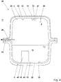
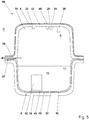
- Fig. 4 shows a further variant according to the invention of a liquid container 38.
- the liquid container 38 is a plastic fuel container 38 for a motor vehicle. To avoid repetition, only the differences in the exemplary embodiment according to FIG Fig. 4 to the last discussed embodiment according to Fig. 3 received. The same features are assigned the same reference symbols.
- a plastic 40 is locally injected, which is used to connect molded elements, connecting parts or functional units.
- the locally injection molded plastic 40 forms a base 40 to which a surge pot 42 is welded.
- the base 40 has been produced by sequential injection molding.
- the barrier film 18 held in an injection molding tool has initially been bonded to the carrier layer 16 in a materially bonded manner.
- the base 40 has been injection-molded onto the side 39 of the barrier layer 18 facing away from the carrier layer 16.
- the surge pot 42 has been materially connected to the base 40 by welding. In this way, the surge pot 42 could with internal Barrier layer 18 can be incorporated into the storage volume 8 without destroying the structural integrity of the barrier layer 18.
- valves such as valves, Venturi nozzles or the like
- Fig. 5 shows a further variant of a liquid container 44 according to the invention.
- the liquid container 44 is a plastic fuel container 44 for a motor vehicle.
- a first barrier layer 46 and a second barrier layer 48 are provided, which are designed as multilayer films 46, 48.
- the first barrier layer 48 has a central layer made of EVOH, which is covered on two sides by adhesion promoter layers made of LDPE.
- the adhesion promoter layers made of LDPE are in turn covered by cover layers made of HDPE.
- This five-layer, cohesively connected layer film composite forms the first barrier layer 46.
- the first carrier layer 12 is also formed from the HDPE of the cover layers of the first barrier layer, so that the first barrier layer 46 and the first carrier layer 12 are cohesively connected with materials of the same type in the injection molding process.
- the second barrier layer 48 of the second half-shell 6 is constructed analogously to this, this in turn being arranged on the inside of the second carrier layer 16.
- the first half-shell can be provided with a single-layer barrier layer or film, while the second half-shell can have a multi-layer or multi-layer film as a barrier layer, or vice versa.
- Fig. 6 shows a further variant of a liquid container 52 according to the invention, in which the barrier layer 14 encloses a web 50 formed on the carrier layer 12 at the end at least in sections.
- the permeation path 26 of the in Fig. 6 The liquid container 52 shown is thus narrowed at the front side by the turning over of the barrier layer 40 in order to keep the diffusion-related emission of fuel 10 into the environment U low.
- Fig. 7 shows a liquid container 54, the first half-shell 4 of which has a web 50, the web 50 being positively seated in a receptacle 56 of the second half-shell 6, which is at least partially complementary.
- the first carrier layer 12 of the first half-shell 4 and the first barrier layer 14 of the first half-shell 4 are according to the embodiment of FIG Fig. 7 made of a laser-transparent plastic, so that the second barrier layer 18, which is formed in the present case from a non-laser-transparent plastic, can be welded to the first carrier layer 12 by means of laser transmission welding with the aid of a laser 58.
- Fig. 8 shows a further variant of a liquid container 60, which differs from the variant of FIG Fig. 7 differs in that the first barrier layer 14 is arranged in an overlapping manner with the second barrier layer 18. In the area of the overlap, the barrier layers 14, 18 are materially connected to one another.
- Fig. 9 shows a further variant of a liquid container 64 according to the invention, the first half-shell 4 forming a cover of the second half-shell 6.
- the first barrier layer 14 is folded over at the end in the area of the circumferential web 50, so that an end face 62 of the web 50 is at least partially covered.
- Fig. 10 shows a further variant of a liquid container 68 according to the invention, wherein in contrast to the variant of Fig. 9 the barrier layers 14, 18 are in the present case connected to one another in a materially bonded manner.
- the first barrier layer 14 is completely folded over around the circumferential web 50, ie the end face 62 is completely covered by the barrier layer 14, so that the barrier layers 14, 18 are welded to one another in the area of an overlap 66.
- the Figures 11-13 describe liquid containers 70, 72, 74 and illustrate how the length of the permeation path 26 can be increased by optimizing the design of the connecting region 24 in order to limit the diffusion-related fuel emission.
- Fig. 11 which describes a liquid container 70
- the permeation path 26 can be lengthened ( Fig. 12 ).
- the permeation path 26 can be lengthened further in order to further restrict the diffusion-related emission.
Landscapes
- Engineering & Computer Science (AREA)
- Mechanical Engineering (AREA)
- Physics & Mathematics (AREA)
- Optics & Photonics (AREA)
- Transportation (AREA)
- Life Sciences & Earth Sciences (AREA)
- Sustainable Development (AREA)
- Sustainable Energy (AREA)
- Chemical & Material Sciences (AREA)
- Combustion & Propulsion (AREA)
- Electromagnetism (AREA)
- Toxicology (AREA)
- Health & Medical Sciences (AREA)
- Manufacturing & Machinery (AREA)
- Injection Moulding Of Plastics Or The Like (AREA)
- Cooling, Air Intake And Gas Exhaust, And Fuel Tank Arrangements In Propulsion Units (AREA)
- Lining Or Joining Of Plastics Or The Like (AREA)
Claims (15)
- Réservoir de liquide destiné à un véhicule automobile,- comportant une première demi-coque (4) qui forme une coque supérieure du réservoir de liquide (2, 28, 38, 44, 52, 54, 60, 64, 68, 70, 72, 74) et- comportant une seconde demi-coque (6) qui forme une coque inférieure du réservoir de liquide (2, 28, 38, 44, 52, 54, 60, 64, 68, 70, 72, 74),- les demi-coques (4, 6) délimitant un volume de stockage (8) permettant de recevoir du liquide (10),- la première demi-coque (4) présentant une première couche de support (12) et une première couche barrière (14, 46),- la seconde demi-coque (6) présentant une seconde couche de support (16) et une seconde couche barrière (18, 48),- la première couche barrière (14, 46) étant disposée à l'extérieur, sur un côté (20) de la première couche de support (12) détourné du volume de stockage (8), et- la seconde couche barrière (18, 48) étant disposée à l'intérieur, sur un côté (22) de la seconde couche de support (16) faisant face au volume de stockage (8).
- Réservoir de liquide selon la revendication 1,
caractérisé- en ce que la première couche de support (12) présente un ou plusieurs éléments moulés (32), des pièces de raccord (34) ou des unités fonctionnelles (36) sur un côté (30) faisant face au volume de stockage (8). - Réservoir de liquide selon la revendication 2,
caractérisé- en ce que les éléments moulés (32), les pièces de raccord (34) ou les unités fonctionnelles (36) s'étendent dans le volume de stockage (8) en saillie et/ou- en ce que les éléments moulés (32) et/ou les pièces de raccord (34) ont été formés d'une seule pièce avec la première couche de support (12) dans un procédé de moulage par injection et/ou ont été moulés par injection séquentiellement sur la première couche de support (12). - Réservoir de liquide selon la revendication 2 ou la revendication 3,
caractérisé- en ce que tous les éléments moulés (32), les pièces de raccord (34) ou les unités fonctionnelles (36) disposés dans le volume de stockage (8) sont disposés sur la première couche de support (12), aucun des éléments moulés, des pièces de raccord ou des unités fonctionnelles disposés dans le volume de stockage n'étant disposés sur la seconde couche barrière (18, 48). - Réservoir de liquide selon l'une des revendications 1 à 3,
caractérisé- en ce que sur un côté (39) de la seconde couche barrière (18, 48) détourné de la seconde couche de support (16), une matière plastique (40) est injectée localement et est utilisée pour relier des éléments moulés, des pièces de raccord ou des unités fonctionnelles (42). - Réservoir de liquide selon l'une des revendications 1 à 5,
caractérisé- en ce qu'au moins l'une des couches barrière (14, 18) est un film monocouche (14, 18), lequel a été relié matériellement à la couche de support (12, 16) associée dans un procédé de moulage par injection,
et/ou- en ce qu'au moins l'une des couches barrière (46, 48) est un film multicouche (46, 48), lequel a été relié à la couche de support (12, 16) associée dans un procédé de moulage par injection. - Réservoir de liquide selon l'une des revendications 1 à 6,
caractérisé- en ce que les demi-coques (4, 6) sont reliées matériellement l'une à l'autre dans une zone de liaison (24), la première couche de support (12) étant reliée matériellement à la seconde couche barrière (18, 48) et/ou à la seconde couche de support dans la zone de liaison (24), et- en ce que la première couche barrière (14, 46) et la seconde couche barrière (18, 48) sont espacées l'une de l'autre dans la zone de liaison (24) et entourent la première couche de support (12) sur deux côtés, la première couche de support (12) formant, dans la zone de liaison (24), un chemin de perméation (26) entre le volume de stockage (8) et un environnement (U) du réservoir de liquide. - Réservoir de liquide selon la revendication 7,
caractérisé- en ce que, vue en coupe transversale, une longueur (1) du chemin de perméation (26) est supérieure ou égale au double de la largeur (b) du chemin de perméation (26),- la largeur (b) du chemin de perméation correspondant à la distance entre les couches barrières (14, 18, 46, 48) dans la zone de liaison (24). - Réservoir de liquide selon la revendication 7 ou 8,
caractérisé- en ce que, vue en coupe transversale, une longueur du chemin de perméation est supérieure à une épaisseur de paroi de la première demi-coque (4) et de la seconde demi-coque (6). - Réservoir de liquide selon l'une des revendications 1 à 6,
caractérisé- en ce que la première couche barrière (14, 46) et la seconde couche barrière (18, 48) sont reliées matériellement l'une à l'autre. - Réservoir de liquide selon l'une des revendications 1 à 10,
caractérisé- en ce que la première couche barrière (14, 46) recouvre sensiblement complètement le côté (20) de la première couche de support (12) détourné du volume de stockage (8) et/ou- en ce que la seconde couche barrière (18, 48) recouvre sensiblement complètement le côté (22) de la seconde couche de support (16) faisant face au volume de stockage (8). - Réservoir de liquide selon l'une des revendications 1 à 11,
caractérisé- en ce qu'au moins l'une des demi-coques (4, 6) présente une entretoise (50), l'entretoise (50) étant située, par complémentarité de forme, dans un logement de forme complémentaire (56) au moins par sections de l'autre demi-coque respective (4, 6)- une liaison matérielle des demi-coques (4, 6) étant formée le long de l'entretoise (50). - Réservoir de liquide selon la revendication 12,
caractérisé- en ce que la couche barrière (14, 46) de la demi-coque (4) présentant l'entretoise (50) est repliée côté extrémité autour de l'entretoise (50) ou enferme l'entretoise (50), la couche barrière recouvrant, au moins partiellement, en particulier un côté frontal (62) de l'entretoise (50). - Réservoir de liquide selon l'une des revendications 12 ou 13,
caractérisé- en ce que l'entretoise (50) est formée au moins par sections à partir d'une matière plastique transparente au laser, la liaison matérielle ayant été formée au moyen d'un soudage laser par transparence. - Procédé de fabrication d'un réservoir de liquide, comportant les étapes de procédé :- de moulage par injection d'une première demi-coque (4) qui forme une coque supérieure du réservoir de liquide (2, 28, 38, 44, 52, 54, 60, 64, 68, 70, 72, 74), la première demi-coque (4) présentant une première couche de support (12) et une première couche barrière (14, 46),- de moulage par injection d'une seconde demi-coque (6) qui forme une coque inférieure du réservoir de liquide (2, 28, 38, 44, 52, 54, 60, 64, 68, 70, 72, 74), la seconde demi-coque (6) présentant une seconde couche de support (16) et une seconde couche barrière (18, 48),- de liaison des demi-coques (4, 6) de telle sorte que les demi-coques (4, 6) délimitent un volume de stockage (8) servant à recevoir du liquide (10), la première couche barrière (14, 46) étant disposée à l'extérieur, sur un côté (20) de la première couche de support (12) détourné du volume de stockage (8), et la seconde couche barrière (18, 48) étant disposée à l'intérieur, sur un côté de la seconde couche de support (16) faisant face au volume de stockage (8).
Applications Claiming Priority (2)
| Application Number | Priority Date | Filing Date | Title |
|---|---|---|---|
| DE102017119708.7A DE102017119708A1 (de) | 2017-08-28 | 2017-08-28 | Flüssigkeitsbehälter für ein Kraftfahrzeug und Verfahren zum Herstellen eines Flüssigkeitsbehälters |
| PCT/EP2018/072929 WO2019042902A1 (fr) | 2017-08-28 | 2018-08-24 | Réservoir de liquide pour un véhicule automobile et procédé de fabrication d'un réservoir de liquide |
Publications (2)
| Publication Number | Publication Date |
|---|---|
| EP3676123A1 EP3676123A1 (fr) | 2020-07-08 |
| EP3676123B1 true EP3676123B1 (fr) | 2021-06-23 |
Family
ID=63491585
Family Applications (1)
| Application Number | Title | Priority Date | Filing Date |
|---|---|---|---|
| EP18765379.5A Active EP3676123B1 (fr) | 2017-08-28 | 2018-08-24 | Réservoir de liquide pour un véhicule automobile et procédé de fabrication d'un réservoir de liquide |
Country Status (7)
| Country | Link |
|---|---|
| US (1) | US20200198459A1 (fr) |
| EP (1) | EP3676123B1 (fr) |
| JP (1) | JP6871479B2 (fr) |
| KR (1) | KR102153866B1 (fr) |
| CN (1) | CN111032408B (fr) |
| DE (1) | DE102017119708A1 (fr) |
| WO (1) | WO2019042902A1 (fr) |
Families Citing this family (10)
| Publication number | Priority date | Publication date | Assignee | Title |
|---|---|---|---|---|
| DE102017222250B4 (de) * | 2017-12-08 | 2023-09-21 | Bayerische Motoren Werke Aktiengesellschaft | Kraftstofftank für ein Kraftfahrzeug, insbesondere für ein Motorrad, sowie Verfahren zum Herstellen eines Kraftstofftanks |
| JP6639559B2 (ja) | 2018-05-16 | 2020-02-05 | 日機装株式会社 | 圧力検出器 |
| JP6637107B2 (ja) | 2018-05-16 | 2020-01-29 | 日機装株式会社 | 圧力検出器 |
| JP6637108B2 (ja) | 2018-05-16 | 2020-01-29 | 日機装株式会社 | 圧力検出器 |
| JP6694475B2 (ja) * | 2018-06-22 | 2020-05-13 | 日機装株式会社 | 医療器具の製造方法及び製造装置 |
| DE102020111015A1 (de) | 2020-04-22 | 2021-10-28 | Röchling Automotive SE & Co. KG | Fahrzeugtank und Verfahren zur Herstellung eines Fahrzeugtanks |
| CN112339305B (zh) * | 2020-09-07 | 2022-05-27 | 江阴市富仁高科股份有限公司 | 一种带有玻璃钢防腐内衬的双层储罐制作工艺 |
| DE102020128011A1 (de) | 2020-10-23 | 2022-04-28 | Röchling Automotive Se & Co.Kg | Sandwich-Kraftfahrzeugtank mit Barrierefolie und angespritzten Tankinnenwänden und Tankaußenwänden |
| DE102020128012A1 (de) | 2020-10-23 | 2022-04-28 | Röchling Automotive SE & Co. KG | Sandwich-Kraftfahrzeugtank mit ausgestülpter Barrierefolie und daran wenigstens lokal angespritztem thermoplastischem Material |
| CN113733450B (zh) * | 2021-09-08 | 2023-03-31 | 亚普汽车部件股份有限公司 | 一种高压复合储氢瓶的焊接塑料内胆结构及成型工艺 |
Family Cites Families (26)
| Publication number | Priority date | Publication date | Assignee | Title |
|---|---|---|---|---|
| US5129544A (en) * | 1990-11-08 | 1992-07-14 | Jacobson Wendell L | Laminated fuel tank structure |
| EP1108598A3 (fr) * | 1999-12-18 | 2003-10-15 | Delphi Technologies, Inc. | Réservoir de carburant avec une barrière imperméable |
| US6613408B1 (en) * | 1999-12-18 | 2003-09-02 | Delphi Technologies, Inc. | Fuel permeation barrier fuel tank |
| ATE271983T1 (de) * | 2000-02-07 | 2004-08-15 | Ti Automotive Technology Ct Gm | Mehrschichtkraftstoffbehälter |
| CA2349939C (fr) * | 2000-06-30 | 2008-04-15 | Kuraray Co., Ltd. | Methode de fabrication d'un article profile ayant d'excellentes proprietes barrieres |
| DE10054876C2 (de) * | 2000-11-06 | 2002-11-07 | Sig Kautex Gmbh & Co Kg | Doppelwandiger Kraftstoffbehälter aus Kunststoff |
| DE10054874C2 (de) * | 2000-11-06 | 2003-05-08 | Sig Kautex Gmbh & Co Kg | Kraftstoffbehälter |
| US6722521B2 (en) | 2002-05-07 | 2004-04-20 | Visteon Global Technologies, Inc. | Low permeation pinchoff connection for bridging a barrier layer and method of making same |
| US7211307B2 (en) * | 2002-07-11 | 2007-05-01 | Visteon Global Techologies, Inc. | Low permeation polymer fuel tank |
| JP2004098886A (ja) * | 2002-09-10 | 2004-04-02 | Fts:Kk | 自動車用燃料タンクおよびその製造方法 |
| US20040071904A1 (en) * | 2002-10-09 | 2004-04-15 | Short William Thomas | Thermoformable sheet and fuel tank incorporating same |
| US6877627B2 (en) * | 2003-01-28 | 2005-04-12 | Ti Group Automotive Systems, L.L.C. | Fuel tank |
| JP2006143057A (ja) * | 2004-11-22 | 2006-06-08 | Fts:Kk | 自動車用燃料タンクおよびその製造方法 |
| JP2006321309A (ja) * | 2005-05-18 | 2006-11-30 | Fts:Kk | 自動車用燃料タンクおよびその製造方法 |
| JP5060194B2 (ja) * | 2007-07-31 | 2012-10-31 | 富士重工業株式会社 | 燃料タンク |
| DE102009023477A1 (de) * | 2009-06-02 | 2011-01-13 | Netstal-Maschinen Ag | Kunststoffbehälter und Herstellungsverfahren |
| JP5350086B2 (ja) * | 2009-06-11 | 2013-11-27 | 本田技研工業株式会社 | 樹脂製燃料タンク |
| JP5420325B2 (ja) * | 2009-06-25 | 2014-02-19 | 愛三工業株式会社 | 燃料タンク |
| JP5350100B2 (ja) * | 2009-06-30 | 2013-11-27 | 愛三工業株式会社 | 燃料タンク |
| US8377368B2 (en) * | 2009-12-11 | 2013-02-19 | Ti Automotive Technology Center Gmbh | Component mounting arrangement |
| DE102010027096A1 (de) * | 2010-07-13 | 2012-01-19 | Kautex Textron Gmbh & Co. Kg | Kraftstoffbehälter aus Kunststoff und Verfahren zu dessen Herstellung |
| IT1401234B1 (it) * | 2010-07-14 | 2013-07-12 | Polymtec Engineering Ag Mauren Fl Succursale Di Lugano | Serbatoio per contenere carburante e relativo procedimento di realizzazione. |
| DE102010060977B4 (de) * | 2010-12-02 | 2023-05-04 | Witte Automotive Gmbh | Schlüssel mit farbigem Gehäuse |
| ITTO20130837A1 (it) * | 2013-10-16 | 2015-04-17 | Plastic Components And Modules Auto Motive S P A | Serbatoio di combustibile per un veicolo con migliorata resistenza alla combustione e procedimento per la sua fabbricazione |
| DE102013018922B4 (de) | 2013-11-13 | 2017-02-02 | Kautex Textron Gmbh & Co. Kg | Betriebsflüssigkeitsbehälter mit Sollbruchstelle |
| JP6418102B2 (ja) * | 2015-08-07 | 2018-11-07 | トヨタ自動車株式会社 | 樹脂製燃料タンクの製造方法 |
-
2017
- 2017-08-28 DE DE102017119708.7A patent/DE102017119708A1/de not_active Withdrawn
-
2018
- 2018-08-24 KR KR1020207007707A patent/KR102153866B1/ko active IP Right Grant
- 2018-08-24 CN CN201880055701.1A patent/CN111032408B/zh active Active
- 2018-08-24 WO PCT/EP2018/072929 patent/WO2019042902A1/fr active Search and Examination
- 2018-08-24 US US16/642,672 patent/US20200198459A1/en not_active Abandoned
- 2018-08-24 EP EP18765379.5A patent/EP3676123B1/fr active Active
- 2018-08-24 JP JP2020511884A patent/JP6871479B2/ja active Active
Also Published As
| Publication number | Publication date |
|---|---|
| EP3676123A1 (fr) | 2020-07-08 |
| KR20200032254A (ko) | 2020-03-25 |
| JP6871479B2 (ja) | 2021-05-12 |
| JP2020531742A (ja) | 2020-11-05 |
| CN111032408A (zh) | 2020-04-17 |
| US20200198459A1 (en) | 2020-06-25 |
| WO2019042902A1 (fr) | 2019-03-07 |
| DE102017119708A1 (de) | 2019-02-28 |
| KR102153866B1 (ko) | 2020-09-08 |
| CN111032408B (zh) | 2021-11-09 |
Similar Documents
| Publication | Publication Date | Title |
|---|---|---|
| EP3676123B1 (fr) | Réservoir de liquide pour un véhicule automobile et procédé de fabrication d'un réservoir de liquide | |
| EP1332063B1 (fr) | Reservoir de carburant en plastique a double paroi | |
| EP3676080B1 (fr) | Réservoir de liquide et procédé de fabrication d'un réservoir de liquide | |
| DE102013004929B4 (de) | Betriebsflüssigkeitsbehälter | |
| EP2236340B1 (fr) | Réservoir pour carburants de véhicule automobile | |
| DE102017119706B4 (de) | Spritzgussverfahren und Flüssigkeitsbehälter für ein Kraftfahrzeug | |
| EP3490776B1 (fr) | Procédé de fabrication d'un réservoir à liquide, réservoir à liquide pour véhicule à moteur, et moule à injection | |
| EP2030755A1 (fr) | Procédé de fabrication d'un manchon | |
| JP2002283853A (ja) | 低透過性付属品、この付属品を利用した低透過性容器、およびこの容器の製造方法 | |
| DE19946530B4 (de) | Doppelwandiger Kraftstoffbehälter | |
| DE60016438T2 (de) | Verschlussvorrichtung und verfahren zum verschliessen der öffnung eines behälters | |
| EP3328672B1 (fr) | Réservoir de liquide de véhicule comprenant un composant fixe | |
| WO2017162412A1 (fr) | Récipient de liquide de travail à élément de renforcement et procédé de fabrication d'un récipient de liquide de travail | |
| DE102013011051A1 (de) | Kraftstoffförderrohre | |
| EP2102026B1 (fr) | Réservoir de carburant en matière thermoplastique avec pièces incorporées fonctionnelles pour la ventilation et l'aération, pour le prélèvement de carburant ou similaire | |
| DE102013001150A1 (de) | Entlüftungsvorrichtung für Flüssigkeitsbehälter, insbesondere für Flüssigkeitsbehälter für eine wässrige Harnstofflösung | |
| EP3810452A1 (fr) | Dispositif d'assemblage pour relier un réservoir de compensation à un récipient à liquide de fonctionnement, réservoir de compensation pour un récipient à liquide de fonctionnement et récipient à liquide de fonctionnement pour un véhicule automobile | |
| DE10018310A1 (de) | Kraftstoffbehälter aus Kunststoff und Verfahren zu dessen Herstellung | |
| WO2007146216A1 (fr) | Réservoir de combustible sulfoné | |
| EP3418095B1 (fr) | Purgeur et dispositif de réservoir | |
| DE102018104071A1 (de) | Verstärkter kraftstofftank und verfahren zur konstruktion eines verstärkten kraftstofftanks | |
| DE60205386T2 (de) | Schweissstruktur für ein Kunststoffteil | |
| EP3692249B1 (fr) | Réservoir de liquide pour véhicule automobile | |
| DE102020128975A1 (de) | Tankschale mit daran flüssigkeitsdicht angeordnetem Montagebauteil | |
| DE202023104407U1 (de) | Rohr mit Flammschutzschicht |
Legal Events
| Date | Code | Title | Description |
|---|---|---|---|
| STAA | Information on the status of an ep patent application or granted ep patent |
Free format text: STATUS: UNKNOWN |
|
| STAA | Information on the status of an ep patent application or granted ep patent |
Free format text: STATUS: THE INTERNATIONAL PUBLICATION HAS BEEN MADE |
|
| PUAI | Public reference made under article 153(3) epc to a published international application that has entered the european phase |
Free format text: ORIGINAL CODE: 0009012 |
|
| STAA | Information on the status of an ep patent application or granted ep patent |
Free format text: STATUS: REQUEST FOR EXAMINATION WAS MADE |
|
| 17P | Request for examination filed |
Effective date: 20200120 |
|
| AK | Designated contracting states |
Kind code of ref document: A1 Designated state(s): AL AT BE BG CH CY CZ DE DK EE ES FI FR GB GR HR HU IE IS IT LI LT LU LV MC MK MT NL NO PL PT RO RS SE SI SK SM TR |
|
| AX | Request for extension of the european patent |
Extension state: BA ME |
|
| DAV | Request for validation of the european patent (deleted) | ||
| DAX | Request for extension of the european patent (deleted) | ||
| GRAP | Despatch of communication of intention to grant a patent |
Free format text: ORIGINAL CODE: EPIDOSNIGR1 |
|
| STAA | Information on the status of an ep patent application or granted ep patent |
Free format text: STATUS: GRANT OF PATENT IS INTENDED |
|
| INTG | Intention to grant announced |
Effective date: 20210311 |
|
| GRAS | Grant fee paid |
Free format text: ORIGINAL CODE: EPIDOSNIGR3 |
|
| GRAA | (expected) grant |
Free format text: ORIGINAL CODE: 0009210 |
|
| STAA | Information on the status of an ep patent application or granted ep patent |
Free format text: STATUS: THE PATENT HAS BEEN GRANTED |
|
| AK | Designated contracting states |
Kind code of ref document: B1 Designated state(s): AL AT BE BG CH CY CZ DE DK EE ES FI FR GB GR HR HU IE IS IT LI LT LU LV MC MK MT NL NO PL PT RO RS SE SI SK SM TR |
|
| REG | Reference to a national code |
Ref country code: GB Ref legal event code: FG4D Free format text: NOT ENGLISH |
|
| REG | Reference to a national code |
Ref country code: CH Ref legal event code: EP |
|
| REG | Reference to a national code |
Ref country code: DE Ref legal event code: R096 Ref document number: 502018005858 Country of ref document: DE Ref country code: AT Ref legal event code: REF Ref document number: 1404020 Country of ref document: AT Kind code of ref document: T Effective date: 20210715 |
|
| REG | Reference to a national code |
Ref country code: IE Ref legal event code: FG4D Free format text: LANGUAGE OF EP DOCUMENT: GERMAN |
|
| REG | Reference to a national code |
Ref country code: LT Ref legal event code: MG9D |
|
| PG25 | Lapsed in a contracting state [announced via postgrant information from national office to epo] |
Ref country code: FI Free format text: LAPSE BECAUSE OF FAILURE TO SUBMIT A TRANSLATION OF THE DESCRIPTION OR TO PAY THE FEE WITHIN THE PRESCRIBED TIME-LIMIT Effective date: 20210623 Ref country code: HR Free format text: LAPSE BECAUSE OF FAILURE TO SUBMIT A TRANSLATION OF THE DESCRIPTION OR TO PAY THE FEE WITHIN THE PRESCRIBED TIME-LIMIT Effective date: 20210623 Ref country code: LT Free format text: LAPSE BECAUSE OF FAILURE TO SUBMIT A TRANSLATION OF THE DESCRIPTION OR TO PAY THE FEE WITHIN THE PRESCRIBED TIME-LIMIT Effective date: 20210623 Ref country code: BG Free format text: LAPSE BECAUSE OF FAILURE TO SUBMIT A TRANSLATION OF THE DESCRIPTION OR TO PAY THE FEE WITHIN THE PRESCRIBED TIME-LIMIT Effective date: 20210923 |
|
| PG25 | Lapsed in a contracting state [announced via postgrant information from national office to epo] |
Ref country code: NO Free format text: LAPSE BECAUSE OF FAILURE TO SUBMIT A TRANSLATION OF THE DESCRIPTION OR TO PAY THE FEE WITHIN THE PRESCRIBED TIME-LIMIT Effective date: 20210923 Ref country code: LV Free format text: LAPSE BECAUSE OF FAILURE TO SUBMIT A TRANSLATION OF THE DESCRIPTION OR TO PAY THE FEE WITHIN THE PRESCRIBED TIME-LIMIT Effective date: 20210623 Ref country code: SE Free format text: LAPSE BECAUSE OF FAILURE TO SUBMIT A TRANSLATION OF THE DESCRIPTION OR TO PAY THE FEE WITHIN THE PRESCRIBED TIME-LIMIT Effective date: 20210623 Ref country code: RS Free format text: LAPSE BECAUSE OF FAILURE TO SUBMIT A TRANSLATION OF THE DESCRIPTION OR TO PAY THE FEE WITHIN THE PRESCRIBED TIME-LIMIT Effective date: 20210623 Ref country code: GR Free format text: LAPSE BECAUSE OF FAILURE TO SUBMIT A TRANSLATION OF THE DESCRIPTION OR TO PAY THE FEE WITHIN THE PRESCRIBED TIME-LIMIT Effective date: 20210924 |
|
| REG | Reference to a national code |
Ref country code: NL Ref legal event code: MP Effective date: 20210623 |
|
| PG25 | Lapsed in a contracting state [announced via postgrant information from national office to epo] |
Ref country code: PT Free format text: LAPSE BECAUSE OF FAILURE TO SUBMIT A TRANSLATION OF THE DESCRIPTION OR TO PAY THE FEE WITHIN THE PRESCRIBED TIME-LIMIT Effective date: 20211025 Ref country code: RO Free format text: LAPSE BECAUSE OF FAILURE TO SUBMIT A TRANSLATION OF THE DESCRIPTION OR TO PAY THE FEE WITHIN THE PRESCRIBED TIME-LIMIT Effective date: 20210623 Ref country code: NL Free format text: LAPSE BECAUSE OF FAILURE TO SUBMIT A TRANSLATION OF THE DESCRIPTION OR TO PAY THE FEE WITHIN THE PRESCRIBED TIME-LIMIT Effective date: 20210623 Ref country code: SM Free format text: LAPSE BECAUSE OF FAILURE TO SUBMIT A TRANSLATION OF THE DESCRIPTION OR TO PAY THE FEE WITHIN THE PRESCRIBED TIME-LIMIT Effective date: 20210623 Ref country code: CZ Free format text: LAPSE BECAUSE OF FAILURE TO SUBMIT A TRANSLATION OF THE DESCRIPTION OR TO PAY THE FEE WITHIN THE PRESCRIBED TIME-LIMIT Effective date: 20210623 Ref country code: SK Free format text: LAPSE BECAUSE OF FAILURE TO SUBMIT A TRANSLATION OF THE DESCRIPTION OR TO PAY THE FEE WITHIN THE PRESCRIBED TIME-LIMIT Effective date: 20210623 Ref country code: EE Free format text: LAPSE BECAUSE OF FAILURE TO SUBMIT A TRANSLATION OF THE DESCRIPTION OR TO PAY THE FEE WITHIN THE PRESCRIBED TIME-LIMIT Effective date: 20210623 Ref country code: ES Free format text: LAPSE BECAUSE OF FAILURE TO SUBMIT A TRANSLATION OF THE DESCRIPTION OR TO PAY THE FEE WITHIN THE PRESCRIBED TIME-LIMIT Effective date: 20210623 |
|
| PG25 | Lapsed in a contracting state [announced via postgrant information from national office to epo] |
Ref country code: PL Free format text: LAPSE BECAUSE OF FAILURE TO SUBMIT A TRANSLATION OF THE DESCRIPTION OR TO PAY THE FEE WITHIN THE PRESCRIBED TIME-LIMIT Effective date: 20210623 |
|
| REG | Reference to a national code |
Ref country code: DE Ref legal event code: R097 Ref document number: 502018005858 Country of ref document: DE |
|
| REG | Reference to a national code |
Ref country code: CH Ref legal event code: PL |
|
| PG25 | Lapsed in a contracting state [announced via postgrant information from national office to epo] |
Ref country code: MC Free format text: LAPSE BECAUSE OF FAILURE TO SUBMIT A TRANSLATION OF THE DESCRIPTION OR TO PAY THE FEE WITHIN THE PRESCRIBED TIME-LIMIT Effective date: 20210623 |
|
| REG | Reference to a national code |
Ref country code: BE Ref legal event code: MM Effective date: 20210831 |
|
| PG25 | Lapsed in a contracting state [announced via postgrant information from national office to epo] |
Ref country code: LI Free format text: LAPSE BECAUSE OF NON-PAYMENT OF DUE FEES Effective date: 20210831 Ref country code: DK Free format text: LAPSE BECAUSE OF FAILURE TO SUBMIT A TRANSLATION OF THE DESCRIPTION OR TO PAY THE FEE WITHIN THE PRESCRIBED TIME-LIMIT Effective date: 20210623 Ref country code: CH Free format text: LAPSE BECAUSE OF NON-PAYMENT OF DUE FEES Effective date: 20210831 |
|
| PLBE | No opposition filed within time limit |
Free format text: ORIGINAL CODE: 0009261 |
|
| STAA | Information on the status of an ep patent application or granted ep patent |
Free format text: STATUS: NO OPPOSITION FILED WITHIN TIME LIMIT |
|
| 26N | No opposition filed |
Effective date: 20220324 |
|
| PG25 | Lapsed in a contracting state [announced via postgrant information from national office to epo] |
Ref country code: LU Free format text: LAPSE BECAUSE OF NON-PAYMENT OF DUE FEES Effective date: 20210824 Ref country code: AL Free format text: LAPSE BECAUSE OF FAILURE TO SUBMIT A TRANSLATION OF THE DESCRIPTION OR TO PAY THE FEE WITHIN THE PRESCRIBED TIME-LIMIT Effective date: 20210623 |
|
| PG25 | Lapsed in a contracting state [announced via postgrant information from national office to epo] |
Ref country code: IT Free format text: LAPSE BECAUSE OF FAILURE TO SUBMIT A TRANSLATION OF THE DESCRIPTION OR TO PAY THE FEE WITHIN THE PRESCRIBED TIME-LIMIT Effective date: 20210623 Ref country code: IE Free format text: LAPSE BECAUSE OF NON-PAYMENT OF DUE FEES Effective date: 20210824 Ref country code: BE Free format text: LAPSE BECAUSE OF NON-PAYMENT OF DUE FEES Effective date: 20210831 |
|
| PG25 | Lapsed in a contracting state [announced via postgrant information from national office to epo] |
Ref country code: CY Free format text: LAPSE BECAUSE OF FAILURE TO SUBMIT A TRANSLATION OF THE DESCRIPTION OR TO PAY THE FEE WITHIN THE PRESCRIBED TIME-LIMIT Effective date: 20210623 |
|
| P01 | Opt-out of the competence of the unified patent court (upc) registered |
Effective date: 20230526 |
|
| PG25 | Lapsed in a contracting state [announced via postgrant information from national office to epo] |
Ref country code: HU Free format text: LAPSE BECAUSE OF FAILURE TO SUBMIT A TRANSLATION OF THE DESCRIPTION OR TO PAY THE FEE WITHIN THE PRESCRIBED TIME-LIMIT; INVALID AB INITIO Effective date: 20180824 |
|
| PGFP | Annual fee paid to national office [announced via postgrant information from national office to epo] |
Ref country code: GB Payment date: 20230822 Year of fee payment: 6 |
|
| PGFP | Annual fee paid to national office [announced via postgrant information from national office to epo] |
Ref country code: FR Payment date: 20230828 Year of fee payment: 6 Ref country code: DE Payment date: 20230725 Year of fee payment: 6 |
|
| PG25 | Lapsed in a contracting state [announced via postgrant information from national office to epo] |
Ref country code: MK Free format text: LAPSE BECAUSE OF FAILURE TO SUBMIT A TRANSLATION OF THE DESCRIPTION OR TO PAY THE FEE WITHIN THE PRESCRIBED TIME-LIMIT Effective date: 20210623 |