EP3676123B1 - Liquid container for a motor vehicle and method for producing a liquid container - Google Patents
Liquid container for a motor vehicle and method for producing a liquid container Download PDFInfo
- Publication number
- EP3676123B1 EP3676123B1 EP18765379.5A EP18765379A EP3676123B1 EP 3676123 B1 EP3676123 B1 EP 3676123B1 EP 18765379 A EP18765379 A EP 18765379A EP 3676123 B1 EP3676123 B1 EP 3676123B1
- Authority
- EP
- European Patent Office
- Prior art keywords
- liquid container
- barrier layer
- shell
- support layer
- layer
- Prior art date
- Legal status (The legal status is an assumption and is not a legal conclusion. Google has not performed a legal analysis and makes no representation as to the accuracy of the status listed.)
- Active
Links
- 239000007788 liquid Substances 0.000 title claims description 105
- 238000004519 manufacturing process Methods 0.000 title claims description 6
- 230000004888 barrier function Effects 0.000 claims description 137
- 238000003860 storage Methods 0.000 claims description 41
- 229920003023 plastic Polymers 0.000 claims description 28
- 238000001746 injection moulding Methods 0.000 claims description 25
- 239000004033 plastic Substances 0.000 claims description 24
- 238000003466 welding Methods 0.000 claims description 11
- 238000000034 method Methods 0.000 claims description 7
- 230000000295 complement effect Effects 0.000 claims description 5
- 230000005540 biological transmission Effects 0.000 claims description 3
- 238000005304 joining Methods 0.000 claims description 2
- 239000010410 layer Substances 0.000 description 181
- 239000000446 fuel Substances 0.000 description 33
- 239000000463 material Substances 0.000 description 15
- 238000009792 diffusion process Methods 0.000 description 14
- 239000012876 carrier material Substances 0.000 description 12
- 229920001903 high density polyethylene Polymers 0.000 description 12
- 239000004700 high-density polyethylene Substances 0.000 description 12
- 229920000219 Ethylene vinyl alcohol Polymers 0.000 description 10
- 229920001684 low density polyethylene Polymers 0.000 description 9
- 239000004702 low-density polyethylene Substances 0.000 description 9
- UFRKOOWSQGXVKV-UHFFFAOYSA-N ethene;ethenol Chemical compound C=C.OC=C UFRKOOWSQGXVKV-UHFFFAOYSA-N 0.000 description 8
- 239000004715 ethylene vinyl alcohol Substances 0.000 description 8
- 239000002356 single layer Substances 0.000 description 7
- 239000002828 fuel tank Substances 0.000 description 5
- 239000004952 Polyamide Substances 0.000 description 4
- 229920002647 polyamide Polymers 0.000 description 4
- 239000002318 adhesion promoter Substances 0.000 description 3
- 230000000694 effects Effects 0.000 description 3
- 239000002991 molded plastic Substances 0.000 description 3
- 239000004696 Poly ether ether ketone Substances 0.000 description 2
- 239000003502 gasoline Substances 0.000 description 2
- 229930195733 hydrocarbon Natural products 0.000 description 2
- 150000002430 hydrocarbons Chemical class 0.000 description 2
- 238000002347 injection Methods 0.000 description 2
- 239000007924 injection Substances 0.000 description 2
- 229920002530 polyetherether ketone Polymers 0.000 description 2
- 229920006012 semi-aromatic polyamide Polymers 0.000 description 2
- 230000002522 swelling effect Effects 0.000 description 2
- 238000013022 venting Methods 0.000 description 2
- XSQUKJJJFZCRTK-UHFFFAOYSA-N Urea Chemical compound NC(N)=O XSQUKJJJFZCRTK-UHFFFAOYSA-N 0.000 description 1
- 238000005299 abrasion Methods 0.000 description 1
- 239000004202 carbamide Substances 0.000 description 1
- 238000002485 combustion reaction Methods 0.000 description 1
- 239000002131 composite material Substances 0.000 description 1
- 239000002826 coolant Substances 0.000 description 1
- 230000001419 dependent effect Effects 0.000 description 1
- 239000002283 diesel fuel Substances 0.000 description 1
- 229920001971 elastomer Polymers 0.000 description 1
- 239000000806 elastomer Substances 0.000 description 1
- 238000005538 encapsulation Methods 0.000 description 1
- 230000008020 evaporation Effects 0.000 description 1
- 238000001704 evaporation Methods 0.000 description 1
- 239000000945 filler Substances 0.000 description 1
- 239000012530 fluid Substances 0.000 description 1
- 239000004811 fluoropolymer Substances 0.000 description 1
- 229920002313 fluoropolymer Polymers 0.000 description 1
- 238000010438 heat treatment Methods 0.000 description 1
- 238000009434 installation Methods 0.000 description 1
- 238000000465 moulding Methods 0.000 description 1
- 238000010943 off-gassing Methods 0.000 description 1
- 230000000149 penetrating effect Effects 0.000 description 1
- 238000004023 plastic welding Methods 0.000 description 1
- 230000005855 radiation Effects 0.000 description 1
- 230000003014 reinforcing effect Effects 0.000 description 1
- 239000011435 rock Substances 0.000 description 1
- 239000000243 solution Substances 0.000 description 1
- 239000000126 substance Substances 0.000 description 1
- 229920002725 thermoplastic elastomer Polymers 0.000 description 1
- 230000008719 thickening Effects 0.000 description 1
Images


Classifications
-
- B—PERFORMING OPERATIONS; TRANSPORTING
- B60—VEHICLES IN GENERAL
- B60K—ARRANGEMENT OR MOUNTING OF PROPULSION UNITS OR OF TRANSMISSIONS IN VEHICLES; ARRANGEMENT OR MOUNTING OF PLURAL DIVERSE PRIME-MOVERS IN VEHICLES; AUXILIARY DRIVES FOR VEHICLES; INSTRUMENTATION OR DASHBOARDS FOR VEHICLES; ARRANGEMENTS IN CONNECTION WITH COOLING, AIR INTAKE, GAS EXHAUST OR FUEL SUPPLY OF PROPULSION UNITS IN VEHICLES
- B60K15/00—Arrangement in connection with fuel supply of combustion engines or other fuel consuming energy converters, e.g. fuel cells; Mounting or construction of fuel tanks
- B60K15/03—Fuel tanks
-
- B—PERFORMING OPERATIONS; TRANSPORTING
- B29—WORKING OF PLASTICS; WORKING OF SUBSTANCES IN A PLASTIC STATE IN GENERAL
- B29C—SHAPING OR JOINING OF PLASTICS; SHAPING OF MATERIAL IN A PLASTIC STATE, NOT OTHERWISE PROVIDED FOR; AFTER-TREATMENT OF THE SHAPED PRODUCTS, e.g. REPAIRING
- B29C45/00—Injection moulding, i.e. forcing the required volume of moulding material through a nozzle into a closed mould; Apparatus therefor
- B29C45/0053—Injection moulding, i.e. forcing the required volume of moulding material through a nozzle into a closed mould; Apparatus therefor combined with a final operation, e.g. shaping
-
- B—PERFORMING OPERATIONS; TRANSPORTING
- B29—WORKING OF PLASTICS; WORKING OF SUBSTANCES IN A PLASTIC STATE IN GENERAL
- B29C—SHAPING OR JOINING OF PLASTICS; SHAPING OF MATERIAL IN A PLASTIC STATE, NOT OTHERWISE PROVIDED FOR; AFTER-TREATMENT OF THE SHAPED PRODUCTS, e.g. REPAIRING
- B29C65/00—Joining or sealing of preformed parts, e.g. welding of plastics materials; Apparatus therefor
- B29C65/02—Joining or sealing of preformed parts, e.g. welding of plastics materials; Apparatus therefor by heating, with or without pressure
- B29C65/14—Joining or sealing of preformed parts, e.g. welding of plastics materials; Apparatus therefor by heating, with or without pressure using wave energy, i.e. electromagnetic radiation, or particle radiation
- B29C65/16—Laser beams
- B29C65/1629—Laser beams characterised by the way of heating the interface
- B29C65/1635—Laser beams characterised by the way of heating the interface at least passing through one of the parts to be joined, i.e. laser transmission welding
-
- B—PERFORMING OPERATIONS; TRANSPORTING
- B29—WORKING OF PLASTICS; WORKING OF SUBSTANCES IN A PLASTIC STATE IN GENERAL
- B29C—SHAPING OR JOINING OF PLASTICS; SHAPING OF MATERIAL IN A PLASTIC STATE, NOT OTHERWISE PROVIDED FOR; AFTER-TREATMENT OF THE SHAPED PRODUCTS, e.g. REPAIRING
- B29C65/00—Joining or sealing of preformed parts, e.g. welding of plastics materials; Apparatus therefor
- B29C65/02—Joining or sealing of preformed parts, e.g. welding of plastics materials; Apparatus therefor by heating, with or without pressure
- B29C65/14—Joining or sealing of preformed parts, e.g. welding of plastics materials; Apparatus therefor by heating, with or without pressure using wave energy, i.e. electromagnetic radiation, or particle radiation
- B29C65/16—Laser beams
- B29C65/1677—Laser beams making use of an absorber or impact modifier
- B29C65/1683—Laser beams making use of an absorber or impact modifier coated on the article
-
- B—PERFORMING OPERATIONS; TRANSPORTING
- B29—WORKING OF PLASTICS; WORKING OF SUBSTANCES IN A PLASTIC STATE IN GENERAL
- B29C—SHAPING OR JOINING OF PLASTICS; SHAPING OF MATERIAL IN A PLASTIC STATE, NOT OTHERWISE PROVIDED FOR; AFTER-TREATMENT OF THE SHAPED PRODUCTS, e.g. REPAIRING
- B29C65/00—Joining or sealing of preformed parts, e.g. welding of plastics materials; Apparatus therefor
- B29C65/78—Means for handling the parts to be joined, e.g. for making containers or hollow articles, e.g. means for handling sheets, plates, web-like materials, tubular articles, hollow articles or elements to be joined therewith; Means for discharging the joined articles from the joining apparatus
- B29C65/7802—Positioning the parts to be joined, e.g. aligning, indexing or centring
- B29C65/7805—Positioning the parts to be joined, e.g. aligning, indexing or centring the parts to be joined comprising positioning features
- B29C65/7814—Positioning the parts to be joined, e.g. aligning, indexing or centring the parts to be joined comprising positioning features in the form of inter-cooperating positioning features, e.g. tenons and mortises
-
- B—PERFORMING OPERATIONS; TRANSPORTING
- B29—WORKING OF PLASTICS; WORKING OF SUBSTANCES IN A PLASTIC STATE IN GENERAL
- B29C—SHAPING OR JOINING OF PLASTICS; SHAPING OF MATERIAL IN A PLASTIC STATE, NOT OTHERWISE PROVIDED FOR; AFTER-TREATMENT OF THE SHAPED PRODUCTS, e.g. REPAIRING
- B29C66/00—General aspects of processes or apparatus for joining preformed parts
- B29C66/50—General aspects of joining tubular articles; General aspects of joining long products, i.e. bars or profiled elements; General aspects of joining single elements to tubular articles, hollow articles or bars; General aspects of joining several hollow-preforms to form hollow or tubular articles
- B29C66/51—Joining tubular articles, profiled elements or bars; Joining single elements to tubular articles, hollow articles or bars; Joining several hollow-preforms to form hollow or tubular articles
- B29C66/54—Joining several hollow-preforms, e.g. half-shells, to form hollow articles, e.g. for making balls, containers; Joining several hollow-preforms, e.g. half-cylinders, to form tubular articles
-
- B—PERFORMING OPERATIONS; TRANSPORTING
- B29—WORKING OF PLASTICS; WORKING OF SUBSTANCES IN A PLASTIC STATE IN GENERAL
- B29C—SHAPING OR JOINING OF PLASTICS; SHAPING OF MATERIAL IN A PLASTIC STATE, NOT OTHERWISE PROVIDED FOR; AFTER-TREATMENT OF THE SHAPED PRODUCTS, e.g. REPAIRING
- B29C66/00—General aspects of processes or apparatus for joining preformed parts
- B29C66/70—General aspects of processes or apparatus for joining preformed parts characterised by the composition, physical properties or the structure of the material of the parts to be joined; Joining with non-plastics material
- B29C66/71—General aspects of processes or apparatus for joining preformed parts characterised by the composition, physical properties or the structure of the material of the parts to be joined; Joining with non-plastics material characterised by the composition of the plastics material of the parts to be joined
- B29C66/712—General aspects of processes or apparatus for joining preformed parts characterised by the composition, physical properties or the structure of the material of the parts to be joined; Joining with non-plastics material characterised by the composition of the plastics material of the parts to be joined the composition of one of the parts to be joined being different from the composition of the other part
-
- B—PERFORMING OPERATIONS; TRANSPORTING
- B29—WORKING OF PLASTICS; WORKING OF SUBSTANCES IN A PLASTIC STATE IN GENERAL
- B29C—SHAPING OR JOINING OF PLASTICS; SHAPING OF MATERIAL IN A PLASTIC STATE, NOT OTHERWISE PROVIDED FOR; AFTER-TREATMENT OF THE SHAPED PRODUCTS, e.g. REPAIRING
- B29C66/00—General aspects of processes or apparatus for joining preformed parts
- B29C66/70—General aspects of processes or apparatus for joining preformed parts characterised by the composition, physical properties or the structure of the material of the parts to be joined; Joining with non-plastics material
- B29C66/72—General aspects of processes or apparatus for joining preformed parts characterised by the composition, physical properties or the structure of the material of the parts to be joined; Joining with non-plastics material characterised by the structure of the material of the parts to be joined
- B29C66/723—General aspects of processes or apparatus for joining preformed parts characterised by the composition, physical properties or the structure of the material of the parts to be joined; Joining with non-plastics material characterised by the structure of the material of the parts to be joined being multi-layered
- B29C66/7234—General aspects of processes or apparatus for joining preformed parts characterised by the composition, physical properties or the structure of the material of the parts to be joined; Joining with non-plastics material characterised by the structure of the material of the parts to be joined being multi-layered comprising a barrier layer
-
- B—PERFORMING OPERATIONS; TRANSPORTING
- B29—WORKING OF PLASTICS; WORKING OF SUBSTANCES IN A PLASTIC STATE IN GENERAL
- B29C—SHAPING OR JOINING OF PLASTICS; SHAPING OF MATERIAL IN A PLASTIC STATE, NOT OTHERWISE PROVIDED FOR; AFTER-TREATMENT OF THE SHAPED PRODUCTS, e.g. REPAIRING
- B29C66/00—General aspects of processes or apparatus for joining preformed parts
- B29C66/70—General aspects of processes or apparatus for joining preformed parts characterised by the composition, physical properties or the structure of the material of the parts to be joined; Joining with non-plastics material
- B29C66/73—General aspects of processes or apparatus for joining preformed parts characterised by the composition, physical properties or the structure of the material of the parts to be joined; Joining with non-plastics material characterised by the intensive physical properties of the material of the parts to be joined, by the optical properties of the material of the parts to be joined, by the extensive physical properties of the parts to be joined, by the state of the material of the parts to be joined or by the material of the parts to be joined being a thermoplastic or a thermoset
- B29C66/735—General aspects of processes or apparatus for joining preformed parts characterised by the composition, physical properties or the structure of the material of the parts to be joined; Joining with non-plastics material characterised by the intensive physical properties of the material of the parts to be joined, by the optical properties of the material of the parts to be joined, by the extensive physical properties of the parts to be joined, by the state of the material of the parts to be joined or by the material of the parts to be joined being a thermoplastic or a thermoset characterised by the extensive physical properties of the parts to be joined
- B29C66/7352—Thickness, e.g. very thin
-
- B—PERFORMING OPERATIONS; TRANSPORTING
- B60—VEHICLES IN GENERAL
- B60K—ARRANGEMENT OR MOUNTING OF PROPULSION UNITS OR OF TRANSMISSIONS IN VEHICLES; ARRANGEMENT OR MOUNTING OF PLURAL DIVERSE PRIME-MOVERS IN VEHICLES; AUXILIARY DRIVES FOR VEHICLES; INSTRUMENTATION OR DASHBOARDS FOR VEHICLES; ARRANGEMENTS IN CONNECTION WITH COOLING, AIR INTAKE, GAS EXHAUST OR FUEL SUPPLY OF PROPULSION UNITS IN VEHICLES
- B60K15/00—Arrangement in connection with fuel supply of combustion engines or other fuel consuming energy converters, e.g. fuel cells; Mounting or construction of fuel tanks
- B60K15/03—Fuel tanks
- B60K15/03177—Fuel tanks made of non-metallic material, e.g. plastics, or of a combination of non-metallic and metallic material
-
- B—PERFORMING OPERATIONS; TRANSPORTING
- B29—WORKING OF PLASTICS; WORKING OF SUBSTANCES IN A PLASTIC STATE IN GENERAL
- B29C—SHAPING OR JOINING OF PLASTICS; SHAPING OF MATERIAL IN A PLASTIC STATE, NOT OTHERWISE PROVIDED FOR; AFTER-TREATMENT OF THE SHAPED PRODUCTS, e.g. REPAIRING
- B29C65/00—Joining or sealing of preformed parts, e.g. welding of plastics materials; Apparatus therefor
- B29C65/02—Joining or sealing of preformed parts, e.g. welding of plastics materials; Apparatus therefor by heating, with or without pressure
- B29C65/06—Joining or sealing of preformed parts, e.g. welding of plastics materials; Apparatus therefor by heating, with or without pressure using friction, e.g. spin welding
-
- B—PERFORMING OPERATIONS; TRANSPORTING
- B29—WORKING OF PLASTICS; WORKING OF SUBSTANCES IN A PLASTIC STATE IN GENERAL
- B29C—SHAPING OR JOINING OF PLASTICS; SHAPING OF MATERIAL IN A PLASTIC STATE, NOT OTHERWISE PROVIDED FOR; AFTER-TREATMENT OF THE SHAPED PRODUCTS, e.g. REPAIRING
- B29C65/00—Joining or sealing of preformed parts, e.g. welding of plastics materials; Apparatus therefor
- B29C65/02—Joining or sealing of preformed parts, e.g. welding of plastics materials; Apparatus therefor by heating, with or without pressure
- B29C65/08—Joining or sealing of preformed parts, e.g. welding of plastics materials; Apparatus therefor by heating, with or without pressure using ultrasonic vibrations
-
- B—PERFORMING OPERATIONS; TRANSPORTING
- B29—WORKING OF PLASTICS; WORKING OF SUBSTANCES IN A PLASTIC STATE IN GENERAL
- B29C—SHAPING OR JOINING OF PLASTICS; SHAPING OF MATERIAL IN A PLASTIC STATE, NOT OTHERWISE PROVIDED FOR; AFTER-TREATMENT OF THE SHAPED PRODUCTS, e.g. REPAIRING
- B29C65/00—Joining or sealing of preformed parts, e.g. welding of plastics materials; Apparatus therefor
- B29C65/02—Joining or sealing of preformed parts, e.g. welding of plastics materials; Apparatus therefor by heating, with or without pressure
- B29C65/10—Joining or sealing of preformed parts, e.g. welding of plastics materials; Apparatus therefor by heating, with or without pressure using hot gases (e.g. combustion gases) or flames coming in contact with at least one of the parts to be joined
-
- B—PERFORMING OPERATIONS; TRANSPORTING
- B29—WORKING OF PLASTICS; WORKING OF SUBSTANCES IN A PLASTIC STATE IN GENERAL
- B29C—SHAPING OR JOINING OF PLASTICS; SHAPING OF MATERIAL IN A PLASTIC STATE, NOT OTHERWISE PROVIDED FOR; AFTER-TREATMENT OF THE SHAPED PRODUCTS, e.g. REPAIRING
- B29C65/00—Joining or sealing of preformed parts, e.g. welding of plastics materials; Apparatus therefor
- B29C65/02—Joining or sealing of preformed parts, e.g. welding of plastics materials; Apparatus therefor by heating, with or without pressure
- B29C65/14—Joining or sealing of preformed parts, e.g. welding of plastics materials; Apparatus therefor by heating, with or without pressure using wave energy, i.e. electromagnetic radiation, or particle radiation
-
- B—PERFORMING OPERATIONS; TRANSPORTING
- B29—WORKING OF PLASTICS; WORKING OF SUBSTANCES IN A PLASTIC STATE IN GENERAL
- B29C—SHAPING OR JOINING OF PLASTICS; SHAPING OF MATERIAL IN A PLASTIC STATE, NOT OTHERWISE PROVIDED FOR; AFTER-TREATMENT OF THE SHAPED PRODUCTS, e.g. REPAIRING
- B29C66/00—General aspects of processes or apparatus for joining preformed parts
- B29C66/01—General aspects dealing with the joint area or with the area to be joined
- B29C66/05—Particular design of joint configurations
- B29C66/10—Particular design of joint configurations particular design of the joint cross-sections
- B29C66/13—Single flanged joints; Fin-type joints; Single hem joints; Edge joints; Interpenetrating fingered joints; Other specific particular designs of joint cross-sections not provided for in groups B29C66/11 - B29C66/12
- B29C66/131—Single flanged joints, i.e. one of the parts to be joined being rigid and flanged in the joint area
- B29C66/1312—Single flange to flange joints, the parts to be joined being rigid
-
- B—PERFORMING OPERATIONS; TRANSPORTING
- B29—WORKING OF PLASTICS; WORKING OF SUBSTANCES IN A PLASTIC STATE IN GENERAL
- B29C—SHAPING OR JOINING OF PLASTICS; SHAPING OF MATERIAL IN A PLASTIC STATE, NOT OTHERWISE PROVIDED FOR; AFTER-TREATMENT OF THE SHAPED PRODUCTS, e.g. REPAIRING
- B29C66/00—General aspects of processes or apparatus for joining preformed parts
- B29C66/70—General aspects of processes or apparatus for joining preformed parts characterised by the composition, physical properties or the structure of the material of the parts to be joined; Joining with non-plastics material
- B29C66/71—General aspects of processes or apparatus for joining preformed parts characterised by the composition, physical properties or the structure of the material of the parts to be joined; Joining with non-plastics material characterised by the composition of the plastics material of the parts to be joined
-
- B—PERFORMING OPERATIONS; TRANSPORTING
- B29—WORKING OF PLASTICS; WORKING OF SUBSTANCES IN A PLASTIC STATE IN GENERAL
- B29D—PRODUCING PARTICULAR ARTICLES FROM PLASTICS OR FROM SUBSTANCES IN A PLASTIC STATE
- B29D22/00—Producing hollow articles
- B29D22/003—Containers for packaging, storing or transporting, e.g. bottles, jars, cans, barrels, tanks
-
- B—PERFORMING OPERATIONS; TRANSPORTING
- B29—WORKING OF PLASTICS; WORKING OF SUBSTANCES IN A PLASTIC STATE IN GENERAL
- B29L—INDEXING SCHEME ASSOCIATED WITH SUBCLASS B29C, RELATING TO PARTICULAR ARTICLES
- B29L2031/00—Other particular articles
- B29L2031/712—Containers; Packaging elements or accessories, Packages
- B29L2031/7172—Fuel tanks, jerry cans
-
- B—PERFORMING OPERATIONS; TRANSPORTING
- B60—VEHICLES IN GENERAL
- B60K—ARRANGEMENT OR MOUNTING OF PROPULSION UNITS OR OF TRANSMISSIONS IN VEHICLES; ARRANGEMENT OR MOUNTING OF PLURAL DIVERSE PRIME-MOVERS IN VEHICLES; AUXILIARY DRIVES FOR VEHICLES; INSTRUMENTATION OR DASHBOARDS FOR VEHICLES; ARRANGEMENTS IN CONNECTION WITH COOLING, AIR INTAKE, GAS EXHAUST OR FUEL SUPPLY OF PROPULSION UNITS IN VEHICLES
- B60K15/00—Arrangement in connection with fuel supply of combustion engines or other fuel consuming energy converters, e.g. fuel cells; Mounting or construction of fuel tanks
- B60K15/03—Fuel tanks
- B60K2015/03032—Manufacturing of fuel tanks
- B60K2015/03046—Manufacturing of fuel tanks made from more than one layer
-
- B—PERFORMING OPERATIONS; TRANSPORTING
- B60—VEHICLES IN GENERAL
- B60K—ARRANGEMENT OR MOUNTING OF PROPULSION UNITS OR OF TRANSMISSIONS IN VEHICLES; ARRANGEMENT OR MOUNTING OF PLURAL DIVERSE PRIME-MOVERS IN VEHICLES; AUXILIARY DRIVES FOR VEHICLES; INSTRUMENTATION OR DASHBOARDS FOR VEHICLES; ARRANGEMENTS IN CONNECTION WITH COOLING, AIR INTAKE, GAS EXHAUST OR FUEL SUPPLY OF PROPULSION UNITS IN VEHICLES
- B60K15/00—Arrangement in connection with fuel supply of combustion engines or other fuel consuming energy converters, e.g. fuel cells; Mounting or construction of fuel tanks
- B60K15/03—Fuel tanks
- B60K2015/03032—Manufacturing of fuel tanks
- B60K2015/03059—Fuel tanks with double shells or more
-
- B—PERFORMING OPERATIONS; TRANSPORTING
- B60—VEHICLES IN GENERAL
- B60K—ARRANGEMENT OR MOUNTING OF PROPULSION UNITS OR OF TRANSMISSIONS IN VEHICLES; ARRANGEMENT OR MOUNTING OF PLURAL DIVERSE PRIME-MOVERS IN VEHICLES; AUXILIARY DRIVES FOR VEHICLES; INSTRUMENTATION OR DASHBOARDS FOR VEHICLES; ARRANGEMENTS IN CONNECTION WITH COOLING, AIR INTAKE, GAS EXHAUST OR FUEL SUPPLY OF PROPULSION UNITS IN VEHICLES
- B60K15/00—Arrangement in connection with fuel supply of combustion engines or other fuel consuming energy converters, e.g. fuel cells; Mounting or construction of fuel tanks
- B60K15/03—Fuel tanks
- B60K2015/03486—Fuel tanks characterised by the materials the tank or parts thereof are essentially made from
- B60K2015/03493—Fuel tanks characterised by the materials the tank or parts thereof are essentially made from made of plastics
Definitions
- the present invention relates to a liquid container for a motor vehicle and a method for producing a liquid container.
- a large number of operating fluids are carried in modern motor vehicles, such as fuel, urea solution for exhaust gas aftertreatment or coolant.
- the liquids are each held in a liquid container.
- plastic fuel tanks are used to store fuel.
- Such plastic fuel tanks should ideally be light, crash-proof and low in emissions.
- emissions the increasingly strict legal limit values for the maximum permissible fuel evaporation emissions of hydrocarbons into the environment must be complied with. This requires the avoidance of fuel leaks under all operating conditions, such as during refueling, including refueling venting, during operational venting, i.e. fuel outgassing when the temperature of a tank system rises, as well as the diffusion of hydrocarbons through the container wall.
- known fuel containers have a diffusion barrier on. If such a fuel tank is formed by assembling two injection-molded half-shells, an inner barrier layer can be arranged on a carrier material for each half-shell, for example.
- the disadvantage here is that any connection or shaped elements of the carrier material that are integrated in the injection molding and project into the storage volume break through the barrier layer and thus form permeation paths through which there is increased fuel emission.
- the document US2011 / 140314 describes a liquid container with a first half-shell and with a second half-shell, the half-shells delimiting a storage volume for receiving liquid, the half-shells having two carrier layers with a barrier layer in between.
- the invention is based on the technical problem of specifying a liquid container and a method for producing a liquid container which do not have the disadvantages described above, or at least to a lesser extent, and in particular enable a reduced diffusion-related emission of a liquid container.
- the first half-shell is an upper shell of a plastic fuel tank for a motor vehicle.
- the second half-shell is a lower shell of the plastic fuel tank.
- the upper shell When installed, the upper shell faces the vehicle. In the fully assembled state, the lower shell faces away from the vehicle or faces the street or lane. Due to the internal arrangement of the second barrier layer, the second barrier layer is protected from mechanical abrasion, e.g. from falling rocks, during vehicle operation.
- the upper shell can thus be used to attach attachments or molded elements on the inside, in particular to weld them on, without breaking through the first barrier layer.
- the first carrier layer has one or more shaped elements, connection parts or functional units on a side facing the storage volume.
- This can be, for example, valve holders, clips for the form-fitting and force-fitting fastening of functional units or bases for the material-fitting connection of functional units.
- the first barrier layer is arranged on a side of the first carrier layer facing away from the storage volume, the molded elements, connection parts or functional units can be arranged, sprayed or applied on the side of the first carrier layer facing the storage volume without the first barrier layer being interrupted.
- they can be formed integrally or in one piece in an injection molding process Molded elements are produced without compromising the structural integrity of the first barrier layer.
- the shaped elements, connecting parts or functional units can, for example, be elements that protrude into the storage volume.
- the molded elements and / or connection parts can have been formed in one piece with the first carrier layer in an injection molding process and / or have been injection-molded sequentially onto the first carrier layer.
- the integral connection of the molded elements and / or connection parts which takes place in one piece in the injection molding process, has the advantage that inexpensive production of the molded elements and / or connection parts is possible.
- the sequential molding on of the molded elements and / or connecting parts offers the advantage of greater freedom of design with regard to the wall thickness and position of the molded elements and / or connecting parts.
- all shaped elements, connection parts or functional units arranged in the storage volume are arranged on the first carrier layer, with no shaped elements, connection parts or functional units arranged in the storage volume being arranged on the second barrier layer. In this way, all required shaped elements, connection parts or functional units can be arranged within the liquid container without the need to break through or interrupt the first barrier layer or the second barrier layer.
- a plastic is locally injection-molded on a side of the second barrier layer facing away from the second carrier layer, which plastic is used to connect one or more shaped elements, connecting parts or functional units is used.
- a carrier material can be locally injected onto the second barrier layer by sequential injection molding on a side of the barrier layer facing away from the carrier layer.
- the locally injection-molded plastic can, for example, be a base or plate-like element made of carrier material, to which, for example, a surge pot can be welded or glued.
- a functional unit can be arranged in the area of the second half-shell with an internal barrier layer without breaking through or interrupting the second barrier layer.
- the barrier effect of the second barrier layer can thus be maintained, with molded elements, connection parts or functional units also being able to be arranged in the area of the locally molded plastic of the lower half-shell.
- At least one of the barrier layers can be a single-layer film that has been materially bonded to the assigned carrier layer in an injection molding process.
- the film can be accommodated in a tool half of an injection molding tool and injected or back-injected with plasticized carrier material.
- the injection molding process creates an integral connection between the barrier film and the carrier layer. In this way, a half-shell with a carrier layer and barrier film can be produced inexpensively and with little use of material.
- At least one of the barrier layers is a multi-layer film that has been materially bonded to the assigned carrier layer in an injection molding process.
- a multi-layer film can, for example, be a five-layer film which has a central layer made of EVOH (Ethylene-vinyl alcohol copolymer), the EVOH layer is covered on both sides by an LDPE (low-density polyethylene) layer, and the LDPE layers in turn are covered by HDPE (high-density polyethylene) layers.
- EVOH Ethylene-vinyl alcohol copolymer
- the cover layers of a multilayer film can in particular be of the same type as the carrier material in order to achieve a reliable material connection between the carrier material and the barrier film.
- the barrier effect of a multi-layer film can largely be provided by an EVOH layer, while the LDPE layers each serve as an adhesion promoter to the outer HDPE layers and the HDPE layers in turn are intended for reliable adhesion or material connection with a carrier material can be, wherein the carrier material can also consist of the HDPE of the outer layers of the barrier film.
- the liquid container can be a plastic fuel container for holding a gasoline or diesel fuel.
- the barrier layers and / or the carrier layers are particularly suitable for being in contact with a diesel or gasoline fuel.
- the material of the barrier film and the material of the carrier layer must therefore be suitable in terms of their swelling properties for being in direct contact with a liquid fuel.
- Both the carrier material and the barrier layer must be suitable for use in direct contact with fuel in terms of their chemical resistance and swelling properties.
- the single-layer or multi-layer carrier layer can have one or more of the following materials or consist of one or more of the following materials: elastomer, thermoplastic Elastomer, HDPE (high-density polyethylene), fiber-reinforced polyamide, PA (polyamide), partially aromatic polyamide, impact-resistant polyamide.
- the single or multi-layer barrier layer can have one or more of the following materials or consist of one or more of the following materials: EVOH (ethylene-vinyl alcohol copolymer), LDPE (low-density polyethylene), PEEK (polyetheretherketone), PA (polyamide), partially aromatic polyamide, HDPE (high-density polyethylene), fluoropolymer.
- the barrier layer can be made up of three layers of PA and EVOH, with a central EVOH layer being covered or bordered on two sides by PA cover layers.
- a six-layer wall structure, for example, or the five-layer structure made of HDPE, LDPE and EVOH, which has already been described above, can also be provided.
- the half-shells are materially connected to one another in a connection area, the first carrier layer in the connection area being materially connected to the second barrier layer and / or the second carrier layer, the first barrier layer and the second barrier layer in the Connection area are spaced apart from one another and border the first carrier layer on two sides, the first carrier layer in the connection area forming a permeation path between the storage volume and the surroundings of the liquid container.
- the cohesive connection of the half-shells to form a closed liquid container can be effected by a plastic welding process, in particular non-contact processes or non-contact welding processes. These include, for example, heating element welding, vibration welding, radiation welding, ultrasonic welding or hot gas welding.
- the two barrier layers thus do not form a closed barrier bubble that would essentially completely enclose the storage volume, i.e. except for the connections that are mandatory for a tank, but rather it a section of first carrier material is present in the connection area, via which there is a diffusion-effective connection between the storage volume and an environment which is not limited by the barrier films.
- a length of the permeation path is greater than or equal to twice the width of the permeation path, the width of the permeation path corresponding to the distance between the barrier layers in the connection area.
- such a permeation path should be made as long and narrow as possible in the connection area in order to keep the diffusion-related emission low.
- a length of the permeation path is greater than a wall thickness of the first half-shell and the second half-shell.
- Such a configuration can be achieved, for example, in that the permeation path runs inclined relative to a horizontal plane when viewed in the installation position of the liquid container.
- the permeation path or a connection area formed between the half-shells can run inclined or inclined in order to constructively lengthen the permeation path without significantly increasing the dimensions of the liquid container.
- first barrier layer and the second barrier layer are materially connected to one another.
- no permeation path is formed in a connection area between the half-shells and the barrier layers form an essentially closed barrier bubble which essentially completely encloses the storage volume of the liquid container, with the restriction that the connections that are mandatory for a tank, such as filler neck, vent and / or removal opening are provided. In this way, diffusion-related emission can be reliably limited.
- connection openings penetrating the wall of a half-shell can be provided.
- the connection openings can have been produced by injection molding.
- the first barrier layer essentially completely covers the side of the first carrier layer facing away from the storage volume. In this way, a reliable encapsulation of a liquid fuel that is to be stored, for example, can be achieved.
- the second barrier layer is on the side facing the storage volume substantially completely covered by the second carrier layer. This in turn serves to reliably reduce diffusion-related emissions.
- At least one of the half-shells of the liquid container has a web, the web sitting positively in an at least partially complementary shaped receptacle of the respective other half-shell, a material connection of the half-shells being formed along the web.
- the first half-shell can be provided with such a web, wherein the first half-shell can in particular form a cover for the second half-shell.
- the first and the second half-shell can be constructed asymmetrically, the second half-shell, for example, forming an upwardly open shell that can be closed with the first half-shell.
- the web can form a centering, so that when the first and second half-shells are joined together, a reliable material connection is achieved along the entire circumferential joining area.
- the first half-shell can therefore, for example, form a cover that is self-centering with respect to the second half-shell.
- a freely protruding wall section of the second half-shell which can be provided to accommodate the first half-shell, can, for example, have a circumferential assembly bevel, which runs inclined to a horizontal plane in the installed state of the liquid container in order to constructively form an extended permeation path without significantly increasing the component dimensions of the liquid container.
- the first half-shell can have a recess or fold which is shaped complementary to the bevel, which can be formed by a welding collar or web surrounding the first half-shell and which can be centered on the second half-shell.
- the barrier layer of the half-shell having the web is folded over at the end around the web or encloses the web, the barrier layer in particular at least partially covering an end face of the web. If the web is provided on the first half-shell with an external barrier layer, for example, enclosing the web at least in sections can narrow the width of a permeation path between the barrier layers locally in the area of the exit of the permeation path towards the environment in order to increase the barrier effect.
- the outer barrier layer or barrier film of the first half-shell which is turned around the end of the web, rests against the second barrier layer of the second half-shell and / or is connected to it in a materially bonded manner.
- an essentially closed barrier bubble can again be formed, which essentially completely surrounds the storage volume on the circumferential side.
- the web is formed at least in sections from a laser-transparent plastic, the material connection having been formed by means of laser transmission welding. In this way, a quick, high-quality welded joint can be achieved.
- the wall thickness of one of the carrier layers taken by itself can be 2 mm to 6 mm, in particular 2 mm to 4 mm.
- This small wall thickness can be formed over, for example, 90% of the entire surface of a half-shell, with local reinforcing ribs, outlets or other local thickenings being able to be provided.
- the thickness of one of the barrier layers, in particular barrier films, can be 100 ⁇ m to 1000 ⁇ m.
- the invention relates to a method according to claim 15.
- the method according to the invention enables a liquid container to be specified which has a high level of security offers compared to diffusion-related emission and at the same time enables the connection of attachments inside or in the storage volume without breaking through the first barrier layer.
- Fig. 1 shows a liquid container 2 for a motor vehicle in a cross section.
- the liquid container 2 is a plastic fuel container 2.
- the liquid container 2 has a first half-shell 4 and a second half-shell 6.
- the half-shells 4, 6 delimit a storage volume 8 for holding liquid 10.
- the liquid 10 in the present case is fuel 10 for operating an internal combustion engine of a motor vehicle.
- the first half-shell 4 has a first carrier layer 12 and a first barrier layer 14.
- the second half-shell 6 has a second carrier layer 16 and a second barrier layer 18.
- the first barrier layer 14 is arranged on a side 20 of the first carrier layer 12 facing away from the storage volume 8.
- the second barrier layer 18 is arranged on a side 22 of the second carrier layer 16 facing the storage volume 8.
- the first barrier layer 14 can therefore be referred to as the external barrier layer 14, while the barrier layer 18 can be referred to as the internal barrier layer 18.
- the first barrier layer 14 is a single-layer film that has been materially bonded to the carrier layer 12 in an injection molding process. Furthermore, the second carrier layer 16 has also been injected onto the second barrier layer 18 in an injection molding process in order to bond the second barrier layer 18 to the second carrier layer 16 in a materially bonded manner. In the present case, the second barrier layer 18 is also designed as a single-layer film.
- the first barrier layer can be single-layer, in particular a single-layer film
- the second barrier layer can be multilayered, in particular a multilayer film, each of which has been connected to associated carrier layers by injection molding.
- the half-shells 4, 6 are cohesively connected to one another in a connection area 24.
- the first carrier layer 12 is materially connected to the second barrier layer 18 in the connection region 24.
- the first barrier layer 14 and the second barrier layer 18 are spaced apart from one another in the connecting region 24 and enclose the first carrier layer 12 on two sides.
- the first carrier layer 12 forms a permeation path 26 in the connection area 24 between the storage volume 8 and an environment U of the liquid container 2.
- the first barrier layer 14 and the second barrier layer 18 in the connection area 24 do not form a closed barrier bubble that essentially forms the storage volume 8 would completely enclose, but delimit the permeation path 26 on two sides.
- FIG. 8 shows an enlarged illustration of the connection region 24 from FIG Fig. 1 .
- a length l of the permeation path 26 is greater than twice the width b of the permeation path 26.
- the width b of the permeation path 26 corresponds to the spacing of the barrier layers 14, 18 in the connecting area 24 diffusion-related emission of the fuel 10 via the material of the first carrier layer 12 into the environment U takes place.
- Fig. 3 shows a further embodiment of a liquid container 28 according to the invention.
- the liquid container 28 is a plastic fuel container 28 for a motor vehicle.
- the following are related to Fig. 2 the same features are assigned the same reference symbols. To avoid repetition, only the differences from the first exemplary embodiment will be discussed.
- the first carrier layer 12 of the liquid container 28 has a molded element 32, a connection part 34 and a functional unit 36 on a side 30 facing the storage volume 8.
- the molded element 32 is injection-molded in one piece with the first carrier layer 12 and can be used to stiffen the structure.
- the connection part 34 is a clip which can be used to fasten functional units within the liquid container 28.
- the clip 34 has subsequently been materially connected to the carrier layer 12 formed in the injection molding process.
- the functional unit 36 which in the present case can be, for example, a pressure sensor or a fill level sensor.
- the shaped element 32, the connecting parts 34 and the functional unit 36 extend in a cantilever manner into the storage volume 8.
- all the shaped elements 32, connecting parts 34 and functional units 36 arranged in the storage volume, for which are shown individually by way of example, are arranged on the first carrier layer 12, with no shaped elements, connecting parts or functional units arranged in the storage volume 8 being arranged on the second barrier layer 18.
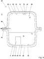
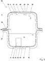
- Fig. 4 shows a further variant according to the invention of a liquid container 38.
- the liquid container 38 is a plastic fuel container 38 for a motor vehicle. To avoid repetition, only the differences in the exemplary embodiment according to FIG Fig. 4 to the last discussed embodiment according to Fig. 3 received. The same features are assigned the same reference symbols.
- a plastic 40 is locally injected, which is used to connect molded elements, connecting parts or functional units.
- the locally injection molded plastic 40 forms a base 40 to which a surge pot 42 is welded.
- the base 40 has been produced by sequential injection molding.
- the barrier film 18 held in an injection molding tool has initially been bonded to the carrier layer 16 in a materially bonded manner.
- the base 40 has been injection-molded onto the side 39 of the barrier layer 18 facing away from the carrier layer 16.
- the surge pot 42 has been materially connected to the base 40 by welding. In this way, the surge pot 42 could with internal Barrier layer 18 can be incorporated into the storage volume 8 without destroying the structural integrity of the barrier layer 18.
- valves such as valves, Venturi nozzles or the like
- Fig. 5 shows a further variant of a liquid container 44 according to the invention.
- the liquid container 44 is a plastic fuel container 44 for a motor vehicle.
- a first barrier layer 46 and a second barrier layer 48 are provided, which are designed as multilayer films 46, 48.
- the first barrier layer 48 has a central layer made of EVOH, which is covered on two sides by adhesion promoter layers made of LDPE.
- the adhesion promoter layers made of LDPE are in turn covered by cover layers made of HDPE.
- This five-layer, cohesively connected layer film composite forms the first barrier layer 46.
- the first carrier layer 12 is also formed from the HDPE of the cover layers of the first barrier layer, so that the first barrier layer 46 and the first carrier layer 12 are cohesively connected with materials of the same type in the injection molding process.
- the second barrier layer 48 of the second half-shell 6 is constructed analogously to this, this in turn being arranged on the inside of the second carrier layer 16.
- the first half-shell can be provided with a single-layer barrier layer or film, while the second half-shell can have a multi-layer or multi-layer film as a barrier layer, or vice versa.
- Fig. 6 shows a further variant of a liquid container 52 according to the invention, in which the barrier layer 14 encloses a web 50 formed on the carrier layer 12 at the end at least in sections.
- the permeation path 26 of the in Fig. 6 The liquid container 52 shown is thus narrowed at the front side by the turning over of the barrier layer 40 in order to keep the diffusion-related emission of fuel 10 into the environment U low.
- Fig. 7 shows a liquid container 54, the first half-shell 4 of which has a web 50, the web 50 being positively seated in a receptacle 56 of the second half-shell 6, which is at least partially complementary.
- the first carrier layer 12 of the first half-shell 4 and the first barrier layer 14 of the first half-shell 4 are according to the embodiment of FIG Fig. 7 made of a laser-transparent plastic, so that the second barrier layer 18, which is formed in the present case from a non-laser-transparent plastic, can be welded to the first carrier layer 12 by means of laser transmission welding with the aid of a laser 58.
- Fig. 8 shows a further variant of a liquid container 60, which differs from the variant of FIG Fig. 7 differs in that the first barrier layer 14 is arranged in an overlapping manner with the second barrier layer 18. In the area of the overlap, the barrier layers 14, 18 are materially connected to one another.
- Fig. 9 shows a further variant of a liquid container 64 according to the invention, the first half-shell 4 forming a cover of the second half-shell 6.
- the first barrier layer 14 is folded over at the end in the area of the circumferential web 50, so that an end face 62 of the web 50 is at least partially covered.
- Fig. 10 shows a further variant of a liquid container 68 according to the invention, wherein in contrast to the variant of Fig. 9 the barrier layers 14, 18 are in the present case connected to one another in a materially bonded manner.
- the first barrier layer 14 is completely folded over around the circumferential web 50, ie the end face 62 is completely covered by the barrier layer 14, so that the barrier layers 14, 18 are welded to one another in the area of an overlap 66.
- the Figures 11-13 describe liquid containers 70, 72, 74 and illustrate how the length of the permeation path 26 can be increased by optimizing the design of the connecting region 24 in order to limit the diffusion-related fuel emission.
- Fig. 11 which describes a liquid container 70
- the permeation path 26 can be lengthened ( Fig. 12 ).
- the permeation path 26 can be lengthened further in order to further restrict the diffusion-related emission.
Landscapes
- Engineering & Computer Science (AREA)
- Mechanical Engineering (AREA)
- Physics & Mathematics (AREA)
- Optics & Photonics (AREA)
- Chemical & Material Sciences (AREA)
- Combustion & Propulsion (AREA)
- Transportation (AREA)
- Life Sciences & Earth Sciences (AREA)
- Sustainable Energy (AREA)
- Sustainable Development (AREA)
- Health & Medical Sciences (AREA)
- Electromagnetism (AREA)
- Toxicology (AREA)
- Manufacturing & Machinery (AREA)
- Injection Moulding Of Plastics Or The Like (AREA)
- Cooling, Air Intake And Gas Exhaust, And Fuel Tank Arrangements In Propulsion Units (AREA)
- Lining Or Joining Of Plastics Or The Like (AREA)
Description
Die vorliegende Erfindung betrifft einen Flüssigkeitsbehälter für ein Kraftfahrzeug und ein Verfahren zum Herstellen eines Flüssigkeitsbehälters.The present invention relates to a liquid container for a motor vehicle and a method for producing a liquid container.
In modernen Kraftfahrzeugen werden eine Vielzahl von Betriebsflüssigkeiten mitgeführt, wie z.B. Kraftstoff, Harnstofflösung zur Abgasnachbehandlung oder Kühlflüssigkeit. Die Flüssigkeiten sind jeweils in einem Flüssigkeitsbehälter aufgenommen. Beispielsweise dienen Kunststoffkraftstoffbehälter zur Bevorratung von Kraftstoff.A large number of operating fluids are carried in modern motor vehicles, such as fuel, urea solution for exhaust gas aftertreatment or coolant. The liquids are each held in a liquid container. For example, plastic fuel tanks are used to store fuel.
Derartige Kunststoffkraftstoffbehälter sollen idealerweise leicht, crashsicher und emissionsarm sein. Bezüglich der Emission müssen die strenger werdenden gesetzlichen Grenzwerte der maximal zulässigen Kraftstoffverdunstungsemissionen von Kohlenwasserstoffen in die Umwelt eingehalten werden. Dies erfordert die Vermeidung von Kraftstoffleckagen unter allen Betriebsbedingungen, wie z.B. bei der Betankung, inklusive der Betankungsentlüftung, bei der Betriebsentlüftung, also der Kraftstoffausgasung bei einem Temperaturanstieg eines Tanksystems, sowie der Diffusion der Kohlenwasserstoffe durch die Behälterwandung.Such plastic fuel tanks should ideally be light, crash-proof and low in emissions. With regard to emissions, the increasingly strict legal limit values for the maximum permissible fuel evaporation emissions of hydrocarbons into the environment must be complied with. This requires the avoidance of fuel leaks under all operating conditions, such as during refueling, including refueling venting, during operational venting, i.e. fuel outgassing when the temperature of a tank system rises, as well as the diffusion of hydrocarbons through the container wall.
Um die Diffusion durch die Behälterwandung gering zu halten, weisen bekannte Kraftstoffbehälter eine Diffusionsbarriere auf. Soweit ein solcher Kraftstoffbehälter durch Zusammensetzen zweier spritzgegossener Halbschalen gebildet ist, kann beispielsweise für jede Halbschale eine innenliegende Barriereschicht an einem Trägermaterial angeordnet sein. Hierbei ist nachteilig, dass etwaige im Spritzguss integrierte, in das Vorratsvolumen ragende Anschluss- oder Formelemente des Trägermaterials die Barriereschicht durchbrechen und damit Permeationspfade bilden, über die es zu einer erhöhten Kraftstoffemission kommt.In order to keep the diffusion through the container wall low, known fuel containers have a diffusion barrier on. If such a fuel tank is formed by assembling two injection-molded half-shells, an inner barrier layer can be arranged on a carrier material for each half-shell, for example. The disadvantage here is that any connection or shaped elements of the carrier material that are integrated in the injection molding and project into the storage volume break through the barrier layer and thus form permeation paths through which there is increased fuel emission.
Das Dokument
Die voranstehend beschriebene technische Problemstellung wird jeweils gelöst durch einen Flüssigkeitsbehälter nach Anspruch 1 und ein Verfahren nach Anspruch 15. Weitere Ausgestaltungen der Erfindung ergeben sich aus den abhängigen Ansprüchen und der nachstehenden Beschreibung.The technical problem described above is solved by a liquid container according to claim 1 and a method according to claim 15. Further embodiments of the invention emerge from the dependent claims and the description below.
Bei der ersten Halbschale handelt es sich um eine Oberschale eines Kunststoffkraftstoffbehälters für ein Kraftfahrzeug. Bei der zweiten Halbschale handelt es sich um eine Unterschale des Kunststoffkraftstoffbehälters.The first half-shell is an upper shell of a plastic fuel tank for a motor vehicle. The second half-shell is a lower shell of the plastic fuel tank.
Die Oberschale ist im Einbauzustand dem Fahrzeug zugewandt. Die Unterschale ist im fertig montierten Zustand dem Fahrzeug abgewandt bzw. der Straße oder Fahrbahn zugewandt. Durch die innenliegende Anordnung der zweiten Barriereschicht ist die zweite Barriereschicht demnach im Fahrzeugbetrieb vor mechanischem Abrieb, z.B. durch Steinschlag, geschützt.When installed, the upper shell faces the vehicle. In the fully assembled state, the lower shell faces away from the vehicle or faces the street or lane. Due to the internal arrangement of the second barrier layer, the second barrier layer is protected from mechanical abrasion, e.g. from falling rocks, during vehicle operation.
Für die erste Barriereschicht, die außenliegend angeordnet ist, ist ein derartiger Schutz aufgrund der dem Fahrzeug zugewandten Anordnung nicht erforderlich. Somit kann die Oberschale dazu verwendet werden, innenliegend Anbauteile oder Formelemente anzubringen, insbesondere anzuschweißen, ohne die erste Barriereschicht zu durchbrechen.For the first barrier layer, which is arranged on the outside, such protection is not necessary due to the arrangement facing the vehicle. The upper shell can thus be used to attach attachments or molded elements on the inside, in particular to weld them on, without breaking through the first barrier layer.
Gemäß einer weiteren Ausgestaltung des Flüssigkeitsbehälters ist vorgesehen, dass die erste Trägerschicht auf einer dem Vorratsvolumen zugewandten Seite eines oder mehrere Formelemente, Anschlussteile oder Funktionseinheiten aufweist. Dabei kann es sich beispielsweise um Ventilhalter, Clips zur formschlüssigen und kraftschlüssigen Befestigung von Funktionseinheiten oder Sockel zum stoffschlüssigen Anbinden von Funktionseinheiten handeln. Dadurch, dass die erste Barriereschicht auf einer dem Vorratsvolumen abgewandten Seite der ersten Trägerschicht angeordnet ist, können die Formelemente, Anschlussteile oder Funktionseinheiten auf der dem Vorratsvolumen zugewandten Seite der ersten Trägerschicht angeordnet, angespritzt oder appliziert werden, ohne dass die erste Barriereschicht unterbrochen wird. Somit können beispielsweise in einem Spritzgussverfahren integral oder einstückig gebildete Formelemente hergestellt werden, ohne die strukturelle Integrität der ersten Barriereschicht zu beeinträchtigen.According to a further embodiment of the liquid container, it is provided that the first carrier layer has one or more shaped elements, connection parts or functional units on a side facing the storage volume. This can be, for example, valve holders, clips for the form-fitting and force-fitting fastening of functional units or bases for the material-fitting connection of functional units. Because the first barrier layer is arranged on a side of the first carrier layer facing away from the storage volume, the molded elements, connection parts or functional units can be arranged, sprayed or applied on the side of the first carrier layer facing the storage volume without the first barrier layer being interrupted. Thus, for example, they can be formed integrally or in one piece in an injection molding process Molded elements are produced without compromising the structural integrity of the first barrier layer.
Bei den Formelementen, Anschlussteilen oder Funktionseinheiten kann es sich beispielsweise um in das Vorratsvolumen auskragend erstreckte Elemente handeln.The shaped elements, connecting parts or functional units can, for example, be elements that protrude into the storage volume.
Die Formelemente und/oder Anschlussteile können in einem Spritzgussverfahren einstückig mit der ersten Trägerschicht gebildet worden sein und/oder sequenziell an die erste Trägerschicht angespritzt worden sein. Die einstückig im Spritzgussverfahren erfolgende, integrale Anbindung der Formelemente und/oder Anschlussteile hat den Vorteil, dass eine kostengünstige Fertigung der Formelemente und/oder Anschlussteile möglich ist. Das sequenzielle Anspritzen der Formelemente und/oder Anschlussteile bietet den Vorteil einer größeren Gestaltungsfreiheit bezüglich der Wandstärke und Position der Formelemente und/oder Anschlussteile.The molded elements and / or connection parts can have been formed in one piece with the first carrier layer in an injection molding process and / or have been injection-molded sequentially onto the first carrier layer. The integral connection of the molded elements and / or connection parts, which takes place in one piece in the injection molding process, has the advantage that inexpensive production of the molded elements and / or connection parts is possible. The sequential molding on of the molded elements and / or connecting parts offers the advantage of greater freedom of design with regard to the wall thickness and position of the molded elements and / or connecting parts.
Nach einer weiteren Ausgestaltung des Flüssigkeitsbehälters ist vorgesehen, dass alle in dem Vorratsvolumen angeordneten Formelemente, Anschlussteile oder Funktionseinheiten an der ersten Trägerschicht angeordnet sind, wobei keine in dem Vorratsvolumen angeordneten Formelemente, Anschlussteile oder Funktionseinheiten an der zweiten Barriereschicht angeordnet sind. Auf diese Weise können alle erforderlichen Formelemente, Anschlussteile oder Funktionseinheiten innerhalb des Flüssigkeitsbehälters angeordnet werden, ohne dass damit ein Durchbrechen bzw. Unterbrechen der ersten Barriereschicht oder der zweiten Barriereschicht erforderlich wäre.According to a further embodiment of the liquid container, it is provided that all shaped elements, connection parts or functional units arranged in the storage volume are arranged on the first carrier layer, with no shaped elements, connection parts or functional units arranged in the storage volume being arranged on the second barrier layer. In this way, all required shaped elements, connection parts or functional units can be arranged within the liquid container without the need to break through or interrupt the first barrier layer or the second barrier layer.
Alternativ kann vorgesehen sein, dass auf einer der zweiten Trägerschicht abgewandten Seite der zweiten Barriereschicht lokal ein Kunststoff angespritzt ist, der zur Anbindung von einem oder mehreren Formelementen, Anschlussteilen oder Funktionseinheiten dient. Hierbei kann beispielsweise nach dem Herstellen der Trägerschicht im Spritzguss auf einer der Trägerschicht abgewandten Seite der Barriereschicht lokal ein Trägerwerkstoff durch sequenzielles Spritzgießen an die zweite Barriereschicht angespritzt werden. Der lokal angespritzte Kunststoff kann beispielsweise ein Sockel oder plattenartiges Element aus Trägermaterial sein, an dem beispielsweise ein Schwalltopf angeschweißt oder angeklebt werden kann. Auf diese Weise kann eine Funktionseinheit im Bereich der zweiten Halbschale mit innenliegender Barriereschicht angeordnet werden, ohne die zweite Barriereschicht zu durchbrechen oder zu unterbrechen. Somit kann die Barrierewirkung der zweiten Barriereschicht aufrechterhalten werden, wobei zudem Formelemente, Anschlussteile oder Funktionseinheiten im Bereich des lokal angespritzten Kunststoffs der unteren Halbschale angeordnet werden können.Alternatively, it can be provided that a plastic is locally injection-molded on a side of the second barrier layer facing away from the second carrier layer, which plastic is used to connect one or more shaped elements, connecting parts or functional units is used. Here, for example, after the production of the carrier layer by injection molding, a carrier material can be locally injected onto the second barrier layer by sequential injection molding on a side of the barrier layer facing away from the carrier layer. The locally injection-molded plastic can, for example, be a base or plate-like element made of carrier material, to which, for example, a surge pot can be welded or glued. In this way, a functional unit can be arranged in the area of the second half-shell with an internal barrier layer without breaking through or interrupting the second barrier layer. The barrier effect of the second barrier layer can thus be maintained, with molded elements, connection parts or functional units also being able to be arranged in the area of the locally molded plastic of the lower half-shell.
Wenigstens eine der Barriereschichten kann eine einlagige Folie sein, die in einem Spritzgussverfahren stoffschlüssig mit der zugeordneten Trägerschicht verbunden worden ist. Hierzu kann die Folie in einer Werkzeughälfte eines Spritzgusswerkzeugs aufgenommen sein und mit plastifiziertem Trägerwerkstoff angespritzt bzw. hinterspritzt werden. Durch den Spritzgussvorgang wird eine stoffschlüssige Verbindung zwischen der Barrierefolie und der Trägerschicht gebildet. So kann eine Halbschale mit Trägerschicht und Barrierefolie kostengünstig und unter geringem Materialeinsatz hergestellt werden.At least one of the barrier layers can be a single-layer film that has been materially bonded to the assigned carrier layer in an injection molding process. For this purpose, the film can be accommodated in a tool half of an injection molding tool and injected or back-injected with plasticized carrier material. The injection molding process creates an integral connection between the barrier film and the carrier layer. In this way, a half-shell with a carrier layer and barrier film can be produced inexpensively and with little use of material.
Alternativ oder ergänzend kann vorgesehen sein, dass wenigstens eine der Barriereschichten eine mehrlagige Folie ist, die in einem Spritzgussverfahren stoffschlüssig mit der zugeordneten Trägerschicht verbunden worden ist. Bei einer solchen mehrlagigen Folie kann es sich beispielsweise um eine fünfschichtige Folie handeln, die eine zentrale Schicht aus EVOH (Ethylen-Vinylalkohol-Copolymer) enthält, die EVOH-Schicht zweiseitig von einer LDPE (Low-density polyethylene) Schicht bedeckt ist, und wobei die LDPE-Schichten ihrerseits wiederum von HDPE-Schichten (High-density polyethylene) bedeckt sind.As an alternative or in addition, it can be provided that at least one of the barrier layers is a multi-layer film that has been materially bonded to the assigned carrier layer in an injection molding process. Such a multi-layer film can, for example, be a five-layer film which has a central layer made of EVOH (Ethylene-vinyl alcohol copolymer), the EVOH layer is covered on both sides by an LDPE (low-density polyethylene) layer, and the LDPE layers in turn are covered by HDPE (high-density polyethylene) layers.
Die Deckschichten einer mehrlagigen Folie können insbesondere artgleich zu dem Trägerwerkstoff ausgebildet sein, um eine zuverlässige stoffschlüssige Verbindung zwischen dem Trägerwerkstoff und der Barrierefolie zu erreichen. So kann die Barrierewirkung einer mehrschichtigen Folie beispielsweise maßgeblich durch eine EVOH-Schicht bereitgestellt werden, während die LDPE-Schichten jeweils als Haftvermittler zu den außenliegenden HDPE-Schichten dienen und die HDPE-Schichten ihrerseits wiederum zur zuverlässigen Anhaftung bzw. stoffschlüssigen Verbindung mit einem Trägermaterial vorgesehen sein kann, wobei das Trägermaterial ebenfalls aus dem HDPE der Deckschichten der Barrierefolie bestehen kann.The cover layers of a multilayer film can in particular be of the same type as the carrier material in order to achieve a reliable material connection between the carrier material and the barrier film. For example, the barrier effect of a multi-layer film can largely be provided by an EVOH layer, while the LDPE layers each serve as an adhesion promoter to the outer HDPE layers and the HDPE layers in turn are intended for reliable adhesion or material connection with a carrier material can be, wherein the carrier material can also consist of the HDPE of the outer layers of the barrier film.
Bei dem Flüssigkeitsbehälter kann es sich um einen Kunststoffkraftstoffbehälter zur Aufnahme eines Otto- oder Dieselkraftstoffs handeln. Die Barriereschichten und/oder die Trägerschichten sind insbesondere dazu geeignet mit einem Diesel oder Benzinkraftstoff in Kontakt zu sein. Der Werkstoff der Barrierefolie und der Werkstoff der Trägerschicht müssen daher hinsichtlich ihrer Quelleigenschaften dazu geeignet sein, in unmittelbarem Kontakt mit einem flüssigen Kraftstoff zu stehen. Sowohl der Trägerwerkstoff als auch die Barriereschicht müssen hinsichtlich ihrer chemischen Beständigkeit und Quellungseigenschaften für den Einsatz in direktem Kraftstoffkontakt geeignet sein.The liquid container can be a plastic fuel container for holding a gasoline or diesel fuel. The barrier layers and / or the carrier layers are particularly suitable for being in contact with a diesel or gasoline fuel. The material of the barrier film and the material of the carrier layer must therefore be suitable in terms of their swelling properties for being in direct contact with a liquid fuel. Both the carrier material and the barrier layer must be suitable for use in direct contact with fuel in terms of their chemical resistance and swelling properties.
Die einlagige oder mehrlagige Trägerschicht kann einen oder mehrere der folgenden Werkstoffe aufweisen oder aus einem oder mehreren der folgenden Werkstoffe bestehen: Elastomer, thermoplastisches Elastomer, HDPE (High-density polyethylene), faserverstärktes Polyamid, PA (Polyamid), teilaromatisches Polyamid, schlagzähes Polyamid.The single-layer or multi-layer carrier layer can have one or more of the following materials or consist of one or more of the following materials: elastomer, thermoplastic Elastomer, HDPE (high-density polyethylene), fiber-reinforced polyamide, PA (polyamide), partially aromatic polyamide, impact-resistant polyamide.
Die einlagige oder mehrlagige Barriereschicht kann einen oder mehrere der folgenden Werkstoffe aufweisen oder aus einem oder mehreren der folgenden Werkstoffe bestehen: EVOH (Ethylen-Vinylalkohol-Copolymer), LDPE (Low-density polyethylene), PEEK (Polyetheretherketon), PA (Polyamid), teilaromatisches Polyamid, HDPE (High-density polyethylene), Fluorpolymer. Z.B. kann die Barriereschicht dreilagig aus PA und EVOH aufgebaut sein, wobei eine zentrale EVOH Lage zweiseitig von PA-Deckschichten bedeckt bzw. eingefasst ist. Es können auch ein beispielsweise sechslagiger Wandungsaufbau oder der voranstehend bereits beschriebene, fünflagige Aufbau aus HDPE, LDPE und EVOH vorgesehen sein.
Gemäß einer weiteren Ausgestaltung des Flüssigkeitsbehälters ist vorgesehen, dass die Halbschalen in einem Verbindungsbereich stoffschlüssig miteinander verbunden sind, wobei die erste Trägerschicht in dem Verbindungsbereich stoffschlüssig mit der zweiten Barriereschicht und/oder der zweiten Trägerschicht verbunden ist, die erste Barriereschicht und die zweite Barriereschicht in dem Verbindungsbereich zueinander beabstandet sind und die erste Trägerschicht zweiseitig einfassen, wobei die erste Trägerschicht in dem Verbindungsbereich einen Permeationspfad zwischen dem Vorratsvolumen und einer Umgebung des Flüssigkeitsbehälters bildet.The single or multi-layer barrier layer can have one or more of the following materials or consist of one or more of the following materials: EVOH (ethylene-vinyl alcohol copolymer), LDPE (low-density polyethylene), PEEK (polyetheretherketone), PA (polyamide), partially aromatic polyamide, HDPE (high-density polyethylene), fluoropolymer. For example, the barrier layer can be made up of three layers of PA and EVOH, with a central EVOH layer being covered or bordered on two sides by PA cover layers. A six-layer wall structure, for example, or the five-layer structure made of HDPE, LDPE and EVOH, which has already been described above, can also be provided.
According to a further embodiment of the liquid container, it is provided that the half-shells are materially connected to one another in a connection area, the first carrier layer in the connection area being materially connected to the second barrier layer and / or the second carrier layer, the first barrier layer and the second barrier layer in the Connection area are spaced apart from one another and border the first carrier layer on two sides, the first carrier layer in the connection area forming a permeation path between the storage volume and the surroundings of the liquid container.
Die stoffschlüssige Verbindung der Halbschalen zu einem geschlossenen Flüssigkeitsbehälter kann durch ein Kunststoffschweißverfahren, insbesondere nicht kontaktlose Verfahren oder kontaktlose Schweißverfahren, erfolgen. Hierzu zählen beispielsweise das Heizelement-Schweißen, das Vibrationsschweißen, das Strahlungsschweißen, Ultraschallschweißen oder das Warmgasschweißen.The cohesive connection of the half-shells to form a closed liquid container can be effected by a plastic welding process, in particular non-contact processes or non-contact welding processes. These include, for example, heating element welding, vibration welding, radiation welding, ultrasonic welding or hot gas welding.
Soweit die Barriereschichten in dem Verbindungsbereich zueinander beabstandet sind und ein Permeationspfad aus Trägermaterial der Trägerschicht gebildet ist, bilden die beiden Barriereschichten damit keine geschlossene Barriereblase, die das Vorratsvolumen im Wesentlichen vollständig, d.h. bis auf die für einen Tank obligatorischen Anschlüsse, einfassen würde, sondern es liegt in dem Verbindungsbereich ein Abschnitt aus erstem Trägermaterial vor, über den eine nicht durch die Barrierefolien begrenzte, diffusionswirksame Verbindung zwischen dem Vorratsvolumen und einer Umgebung besteht.Insofar as the barrier layers are spaced apart from one another in the connection area and a permeation path is formed from the carrier material of the carrier layer, the two barrier layers thus do not form a closed barrier bubble that would essentially completely enclose the storage volume, i.e. except for the connections that are mandatory for a tank, but rather it a section of first carrier material is present in the connection area, via which there is a diffusion-effective connection between the storage volume and an environment which is not limited by the barrier films.
Um die diffusionsbedingte Emission entlang des Permeationspfads gering zu halten, kann vorgesehen sein, dass in einem Querschnitt betrachtet eine Länge des Permeationspfads größer oder gleich dem zweifachen der Breite des Permeationspfads ist, wobei die Breite des Permeationspfads dem Abstand der Barriereschichten in dem Verbindungsbereich entspricht. Mit anderen Worten sollte ein solcher Permeationspfad in dem Verbindungsbereich möglichst länglich und schmal ausgestaltet werden, um die diffusionsbedingte Emission gering zu halten.In order to keep the diffusion-related emission along the permeation path low, it can be provided that, viewed in a cross section, a length of the permeation path is greater than or equal to twice the width of the permeation path, the width of the permeation path corresponding to the distance between the barrier layers in the connection area. In other words, such a permeation path should be made as long and narrow as possible in the connection area in order to keep the diffusion-related emission low.
Es kann demnach alternativ oder ergänzend weiter vorgesehen sein, dass in einem Querschnitt betrachtet eine Länge des Permeationspfads größer ist als eine Wanddicke der ersten Halbschale und der zweiten Halbschale.Accordingly, it can alternatively or additionally be provided that, viewed in a cross section, a length of the permeation path is greater than a wall thickness of the first half-shell and the second half-shell.
Eine solche Ausgestaltung kann beispielsweise dadurch erreicht werden, dass der Permeationspfad relativ zu einer horizontalen Ebene in Einbaulage des Flüssigkeitsbehälters betrachtet geneigt verläuft. So kann der Permeationspfad bzw. ein zwischen den Halbschalen gebildeter Verbindungsbereich geneigt oder schräg verlaufen, um den Permeationspfad konstruktiv zu verlängern ohne die Abmaße des Flüssigkeitsbehälters wesentlich zu vergrößern.Such a configuration can be achieved, for example, in that the permeation path runs inclined relative to a horizontal plane when viewed in the installation position of the liquid container. For example, the permeation path or a connection area formed between the half-shells can run inclined or inclined in order to constructively lengthen the permeation path without significantly increasing the dimensions of the liquid container.
Es kann vorgesehen sein, dass die erste Barriereschicht und die zweite Barriereschicht stoffschlüssig miteinander verbunden sind. In diesem Fall ist in einem Verbindungsbereich zwischen den Halbschalen kein Permeationspfad gebildet und die Barriereschichten bilden eine im Wesentlichen geschlossene Barriereblase, die das Vorratsvolumen des Flüssigkeitsbehälters im Wesentlichen vollständig einfasst, mit der Einschränkung, dass die für einen Tank obligatorischen Anschlüsse wie Einfüllstutzen, Entlüftung und/oder Entnahmeöffnung vorgesehen sind. Auf diese Weise kann eine diffusionsbedingte Emission zuverlässig begrenzt werden.It can be provided that the first barrier layer and the second barrier layer are materially connected to one another. In this case, no permeation path is formed in a connection area between the half-shells and the barrier layers form an essentially closed barrier bubble which essentially completely encloses the storage volume of the liquid container, with the restriction that the connections that are mandatory for a tank, such as filler neck, vent and / or removal opening are provided. In this way, diffusion-related emission can be reliably limited.
Wenn vorliegend davon gesprochen wird, dass die Barriereschichten das Vorratsvolumen im Wesentlichen vollständig einfassen, so betrifft dies daher insbesondere die Vermeidung eines Permeationspfads im Verbindungbereich zwischen den Halbschalen und es versteht sich, dass zum Befüllen des Flüssigkeitsbehälters mit Kraftstoff und zur Entnahme des Kraftstoffs aus dem Flüssigkeitsbehälters Zuleitungen und Abgänge und/oder Entlüftungsventile vorgesehen sind, im Bereich derer die erste oder zweite Barriereschicht lokal durchbrochen ist. Es können demnach die Wandung einer Halbschale durchdringende Anschlussöffnungen vorgesehen sein. Die Anschlussöffnungen können im Spritzgussverfahren hergestellt worden sein.When it is said in the present case that the barrier layers essentially completely enclose the storage volume, this therefore relates in particular to avoiding a permeation path in the connection area between the half-shells and it goes without saying that to fill the liquid container with fuel and to remove the fuel from the liquid container Supply lines and outlets and / or vent valves are provided, in the area of which the first or second barrier layer is locally broken. Accordingly, connection openings penetrating the wall of a half-shell can be provided. The connection openings can have been produced by injection molding.
Nach einer weiteren Ausgestaltung des Flüssigkeitsbehälters ist vorgesehen, dass die erste Barriereschicht die dem Vorratsvolumen abgewandte Seite der ersten Trägerschicht im Wesentlichen vollständig bedeckt. Auf diese Weise kann eine zuverlässige Kapselung eines beispielsweise zu bevorrateten Flüssigkraftstoffs erreicht werden.According to a further embodiment of the liquid container, it is provided that the first barrier layer essentially completely covers the side of the first carrier layer facing away from the storage volume. In this way, a reliable encapsulation of a liquid fuel that is to be stored, for example, can be achieved.
Alternativ oder ergänzend kann vorgesehen sein, dass die zweite Barriereschicht die dem Vorratsvolumen zugewandte Seite der zweiten Trägerschicht im Wesentlichen vollständig bedeckt. Dies dient wiederum der zuverlässigen Verringerung einer diffusionsbedingten Emission.As an alternative or in addition, it can be provided that the second barrier layer is on the side facing the storage volume substantially completely covered by the second carrier layer. This in turn serves to reliably reduce diffusion-related emissions.
Die Formulierung "im Wesentlichen vollständig" trägt wiederum den vorstehend bereits diskutierten, ggf. für ein Tanksystem erforderlichen Zu- und Abgängen Rechnung.The wording “essentially completely” takes into account the inlets and outlets that have already been discussed above and which may be required for a tank system.
Es kann vorgesehen sein, dass wenigstens eine der Halbschalen des Flüssigkeitsbehälters einen Steg hat, wobei der Steg formschlüssig in einer zumindest abschnittsweise komplementär geformten Aufnahme der jeweils anderen Halbschale sitzt, wobei entlang des Stegs eine stoffschlüssige Verbindung der Halbschalen gebildet ist. Beispielsweise kann die erste Halbschale mit einem solchen Steg versehen sein, wobei die erste Halbschale insbesondere einen Deckel für die zweite Halbschale bilden kann.It can be provided that at least one of the half-shells of the liquid container has a web, the web sitting positively in an at least partially complementary shaped receptacle of the respective other half-shell, a material connection of the half-shells being formed along the web. For example, the first half-shell can be provided with such a web, wherein the first half-shell can in particular form a cover for the second half-shell.
Die erste und die zweite Halbschale können asymmetrisch aufgebaut sein, wobei die zweite Halbschale beispielsweise eine nach oben offene Schale bildet, die mit der ersten Halbschale verschließbar ist.The first and the second half-shell can be constructed asymmetrically, the second half-shell, for example, forming an upwardly open shell that can be closed with the first half-shell.
Der Steg kann zusammen mit einer komplementären Form eine Zentrierung bilden, sodass beim Zusammenfügen der ersten und der zweiten Halbschale eine zuverlässige stoffschlüssige Verbindung entlang des gesamten umfangsseitig umlaufenden Fügebereichs erreicht wird. Die erste Halbschale kann demnach zum Beispiel einen bezüglich der zweiten Halbschale selbstzentrieren den Deckel bilden.Together with a complementary shape, the web can form a centering, so that when the first and second half-shells are joined together, a reliable material connection is achieved along the entire circumferential joining area. The first half-shell can therefore, for example, form a cover that is self-centering with respect to the second half-shell.
Ein frei auskragender Wandungsabschnitt der zweiten Halbschale, der zur Aufnahme der ersten Halbschale vorgesehen sein kann, kann beispielsweise eine umlaufende Montagefase haben, die zu einer horizontalen Ebene im Einbauzustand des Flüssigkeitsbehälters geneigt verläuft, um konstruktiv einen verlängerten Permeationspfad auszubilden, ohne die Bauteilabmessungen des Flüssigkeitsbehälters maßgeblich zu erhöhen. Die erste Halbschale kann eine zu der Fase komplementär geformte Ausnehmung oder Falz haben, die durch einen an der ersten Halbschale umlaufenden Schweißkragen oder Steg gebildet sein kann und auf der zweiten Halbschale zentrierbar sein kann.A freely protruding wall section of the second half-shell, which can be provided to accommodate the first half-shell, can, for example, have a circumferential assembly bevel, which runs inclined to a horizontal plane in the installed state of the liquid container in order to constructively form an extended permeation path without significantly increasing the component dimensions of the liquid container. The first half-shell can have a recess or fold which is shaped complementary to the bevel, which can be formed by a welding collar or web surrounding the first half-shell and which can be centered on the second half-shell.
Gemäß einer weiteren Ausgestaltung des Flüssigkeitsbehälters ist vorgesehen, dass die Barriereschicht der den Steg aufweisenden Halbschale endseitig um den Steg umgeschlagen ist oder den Steg umschließt, wobei die Barriereschicht insbesondere eine Stirnseite des Stegs zumindest teilweise bedeckt. Soweit der Steg zum Beispiel an der ersten Halbschale mit außenliegender Barriereschicht vorgesehen ist, kann ein zumindest abschnittsweises Umschließen des Stegs die Breite eines Permeationspfads zwischen den Barriereschichten lokal im Bereich des Austritts des Permeationspfads hin zur Umgebung verschmälern, um die Barrierewirkung zu erhöhen. Alternativ oder ergänzend kann vorgesehen sein, dass die stirnseitig um den Steg umgeschlagene, außenliegende Barriereschicht oder Barrierefolie der ersten Halbschale an der zweiten Barriereschicht der zweiten Halbschale anliegt und/oder mit dieser stoffschlüssig verbunden ist. Auf diese Weise kann wiederum eine im Wesentlichen geschlossene Barriereblase gebildet werden, die das Vorratsvolumen umfangsseitig im Wesentlichen vollständig einfasst.According to a further embodiment of the liquid container, it is provided that the barrier layer of the half-shell having the web is folded over at the end around the web or encloses the web, the barrier layer in particular at least partially covering an end face of the web. If the web is provided on the first half-shell with an external barrier layer, for example, enclosing the web at least in sections can narrow the width of a permeation path between the barrier layers locally in the area of the exit of the permeation path towards the environment in order to increase the barrier effect. As an alternative or in addition, it can be provided that the outer barrier layer or barrier film of the first half-shell, which is turned around the end of the web, rests against the second barrier layer of the second half-shell and / or is connected to it in a materially bonded manner. In this way, an essentially closed barrier bubble can again be formed, which essentially completely surrounds the storage volume on the circumferential side.
Es kann vorgesehen sein, dass der Steg zumindest abschnittsweise aus einem lasertransparenten Kunststoff gebildet ist, wobei die stoffschlüssige Verbindung mittels Laserdurchstrahlschweißen gebildet worden ist. Auf diese Weise kann eine zügige Schweißverbindung hoher Qualität erreicht werden.It can be provided that the web is formed at least in sections from a laser-transparent plastic, the material connection having been formed by means of laser transmission welding. In this way, a quick, high-quality welded joint can be achieved.
Die Wanddicke einer der Trägerschichten für sich genommen kann 2 mm bis 6 mm betragen, insbesondere 2 mm bis 4 mm betragen. Diese geringe Wanddicke kann über beispielsweise 90 % der gesamten Oberfläche einer Halbschale ausgebildet sein, wobei lokale Verstärkungsrippen, Abgänge oder andere lokale Verdickungen vorgesehen sein können.The wall thickness of one of the carrier layers taken by itself can be 2 mm to 6 mm, in particular 2 mm to 4 mm. This small wall thickness can be formed over, for example, 90% of the entire surface of a half-shell, with local reinforcing ribs, outlets or other local thickenings being able to be provided.
Die Dicke einer der Barriereschichten, insbesondere Barrierefolien, kann 100 µm bis 1000 µm betragen.The thickness of one of the barrier layers, in particular barrier films, can be 100 μm to 1000 μm.
In einem zweiten Aspekt betrifft die Erfindung ein Verfahren gemäß Anspruch 15.In a second aspect, the invention relates to a method according to claim 15.
Durch die Kombination einer Halbschale mit außenliegender Barriereschicht mit einer Halbschale mit innenliegender Barriereschicht kann durch das erfindungsgemäße Verfahren ein Flüssigkeitsbehälter angegeben werden, der eine hohe Sicherheit gegenüber diffusionsbedingter Emission bietet und zugleich die Anbindung von Anbauteilen im Inneren bzw. im Vorratsvolumen ermöglicht, ohne die erste Barriereschicht zu durchbrechen.By combining a half-shell with an external barrier layer with a half-shell with an internal barrier layer, the method according to the invention enables a liquid container to be specified which has a high level of security offers compared to diffusion-related emission and at the same time enables the connection of attachments inside or in the storage volume without breaking through the first barrier layer.
Nachfolgend wird die Erfindung anhand einer Ausführungsbeispiele darstellenden Zeichnung näher beschrieben. Es zeigen jeweils schematisch:
- Fig. 1
- einen erfindungsgemäßen Flüssigkeitsbehälter in einem Querschnitt;
- Fig. 2
- eine Ausschnittvergrößerung der
Fig. 1 ; - Fig. 3
- ein weiteres Ausführungsbeispiel eines erfindungsgemäßen Flüssigkeitsbehälters in einem Querschnitt;
- Fig. 4
- ein weiteres Ausführungsbeispiel eines erfindungsgemäßen Flüssigkeitsbehälters in einem Querschnitt;
- Fig. 5
- ein weiteres Ausführungsbeispiel eines erfindungsgemäßen Flüssigkeitsbehälters in einem Querschnitt;
- Fig. 6
- ein weiteres Ausführungsbeispiel eines erfindungsgemäßen Flüssigkeitsbehälters in einem Querschnitt;
- Fig. 7
- ein weiteres Ausführungsbeispiel eines erfindungsgemäßen Flüssigkeitsbehälters in einem Querschnitt;
- Fig. 8
- ein weiteres Ausführungsbeispiel eines erfindungsgemäßen Flüssigkeitsbehälters in einem Querschnitt;
- Fig. 9
- ein weiteres Ausführungsbeispiel eines erfindungsgemäßen Flüssigkeitsbehälters in einem Querschnitt;
- Fig. 10
- ein weiteres Ausführungsbeispiel eines erfindungsgemäßen Flüssigkeitsbehälters in einem Querschnitt;
- Fig. 11
- ein weiteres Ausführungsbeispiel eines erfindungsgemäßen Flüssigkeitsbehälters in einem Querschnitt;
- Fig. 12
- ein weiteres Ausführungsbeispiel eines erfindungsgemäßen Flüssigkeitsbehälters in einem Querschnitt;
- Fig. 13
- ein weiteres Ausführungsbeispiel eines erfindungsgemäßen Flüssigkeitsbehälters in einem Querschnitt.
- Fig. 1
- a liquid container according to the invention in a cross section;
- Fig. 2
- an enlarged section of the
Fig. 1 ; - Fig. 3
- a further embodiment of a liquid container according to the invention in a cross section;
- Fig. 4
- a further embodiment of a liquid container according to the invention in a cross section;
- Fig. 5
- a further embodiment of a liquid container according to the invention in a cross section;
- Fig. 6
- a further embodiment of a liquid container according to the invention in a cross section;
- Fig. 7
- a further embodiment of a liquid container according to the invention in a cross section;
- Fig. 8
- a further embodiment of a liquid container according to the invention in a cross section;
- Fig. 9
- a further embodiment of a liquid container according to the invention in a cross section;
- Fig. 10
- a further embodiment of a liquid container according to the invention in a cross section;
- Fig. 11
- a further embodiment of a liquid container according to the invention in a cross section;
- Fig. 12
- a further embodiment of a liquid container according to the invention in a cross section;
- Fig. 13
- a further embodiment of a liquid container according to the invention in a cross section.
Der Flüssigkeitsbehälter 2 hat eine erste Halbschale 4 und eine zweite Halbschale 6. Die Halbschalen 4, 6 begrenzen ein Vorratsvolumen 8 zur Aufnahme von Flüssigkeit 10. Bei der Flüssigkeit 10 handelt es sich vorliegend um Kraftstoff 10 zum Betrieb eines Verbrennungsmotors eines Kraftfahrzeugs. Die erste Halbschale 4 hat eine erste Trägerschicht 12 und eine erste Barriereschicht 14. Die zweite Halbschale 6 hat eine zweite Trägerschicht 16 und eine zweite Barriereschicht 18.The
Die erste Barriereschicht 14 ist auf einer dem Vorratsvolumen 8 abgewandten Seite 20 der ersten Trägerschicht 12 angeordnet. Die zweite Barriereschicht 18 ist auf einer dem Vorratsvolumen 8 zugewandten Seite 22 der zweiten Trägerschicht 16 angeordnet. Die erste Barriereschicht 14 kann daher als außenliegende Barriereschicht 14 bezeichnet werden, während die Barriereschicht 18 als innenliegende Barriereschicht 18 bezeichnet werden kann.The
In dem Beispiel der
Es versteht sich, dass gemäß weiteren Ausführungsbeispielen der Erfindung die erste Barriereschicht einlagig sein kann, insbesondere eine einlagige Folie, während die zweite Barriereschicht mehrlagig sein kann, insbesondere eine mehrlagige Folie, die jeweils im Spritzgussverfahren mit zugeordneten Trägerschichten verbunden worden sind.It goes without saying that, according to further exemplary embodiments of the invention, the first barrier layer can be single-layer, in particular a single-layer film, while the second barrier layer can be multilayered, in particular a multilayer film, each of which has been connected to associated carrier layers by injection molding.
Die Halbschalen 4, 6 sind in einem Verbindungsbereich 24 stoffschlüssig miteinander verbunden. Dabei ist die erste Trägerschicht 12 in dem Verbindungsbereich 24 stoffschlüssig mit der zweiten Barriereschicht 18 verbunden. Die erste Barriereschicht 14 und die zweite Barriereschicht 18 sind in dem Verbindungsbereich 24 zueinander beabstandet und fassen die erste Trägerschicht 12 zweiseitig ein.The half-
Die erste Trägerschicht 12 bildet in dem Verbindungsbereich 24 einen Permeationspfad 26 zwischen dem Vorratsvolumen 8 und einer Umgebung U des Flüssigkeitsbehälters 2. Mit anderen Worten bilden die erste Barriereschicht 14 und die zweite Barriereschicht 18 im Verbindungsbereich 24 keine geschlossene Barriereblase, die das Vorratsvolumen 8 im Wesentlichen vollständig einfassen würde, sondern begrenzen zweiseitig den Permeationspfad 26.The
Die erste Trägerschicht 12 des Flüssigkeitsbehälters 28 hat auf einer dem Vorratsvolumen 8 zugewandten Seite 30 ein Formelement 32, ein Anschlussteil 34 und eine Funktionseinheit 36. Das Formelement 32 ist im Spritzgussverfahren einstückig mit der ersten Trägerschicht 12 gebildet worden und kann zur Aussteifung der Struktur dienen. Das Anschlussteil 34 ist vorliegend ein Clip, der zur Befestigung von Funktionseinheiten innerhalb des Flüssigkeitsbehälters 28 dienen kann. Der Clip 34 ist nachträglich stoffschlüssig mit der im Spritzgussverfahren geformten Trägerschicht 12 verbunden worden. Dies gilt gleichermaßen für die Funktionseinheit 36, die vorliegend z.B. ein Drucksensor oder Füllstandsensor sein kann.The
Das Formelement 32, das Anschlussteilen 34 und die Funktionseinheit 36 sind in das Vorratsvolumen 8 auskragend erstreckt. In dem vorliegenden Beispiel des Flüssigkeitsbehälters 28 gemäß
Im Unterschied zu dem Flüssigkeitsbehälter 28 aus
Der lokal angespritzte Kunststoff 40 bildet vorliegend einen Sockel 40 an dem ein Schwalltopf 42 angeschweißt ist.In contrast to the
In the present case, the locally injection molded plastic 40 forms a base 40 to which a
Der Sockel 40 ist durch sequenzielles Spritzgießen erzeugt worden. Hierbei ist die in einem Spritzgusswerkzeug gehaltene Barrierefolie 18 zunächst mit der Trägerschicht 16 stoffschlüssig verbunden worden. In einem nachfolgenden, zweiten Spritzgussschritt ist auf der der Trägerschicht 16 abgewandten Seite 39 der Barriereschicht 18 der Sockel 40 angespritzt worden. In einem weiteren Schritt ist der Schwalltopf 42 stoffschlüssig durch Verschweißen mit dem Sockel 40 verbunden worden. Auf diese Weise konnte der Schwalltopf 42 bei innenliegende Barriereschicht 18 in das Vorratsvolumen 8 eingebunden werden, ohne die strukturelle Integrität der Barriereschicht 18 zu zerstören.The
Es können weitere Elemente, wie Ventile, Venturi-Düsen oder dergleichen an dem Sockel oder mehreren separaten Sockeln bzw. lokalen Materialanspritzungen vorgesehen sein.Further elements, such as valves, Venturi nozzles or the like, can be provided on the base or several separate bases or local material injection-molding.
Die erste Barriereschicht 48 weist eine zentrale Schicht aus EVOH auf, die zweiseitig von Haftvermittlerschichten aus LDPE bedeckt ist. Die Haftvermittlerschichten aus LDPE sind wiederum von Deckschichten aus HDPE bedeckt. Dieser fünfschichtige, stoffschlüssig verbundene Schichtfolienverbund bildet die erste Barriereschicht 46. Die erste Trägerschicht 12 ist vorliegend ebenfalls aus dem HDPE der Deckschichten der ersten Barriereschicht gebildet, so dass die erste Barriereschicht 46 und die erste Trägerschicht 12 im Spritzgussverfahren stoffschlüssig mit artgleichen Materialien verbunden worden sind. Die zweite Barriereschicht 48 der zweiten Halbschale 6 ist analog hierzu aufgebaut, wobei diese wiederum innenliegend an der zweiten Trägerschicht 16 angeordnet ist.The
Es versteht sich, dass gemäß weiteren Ausführungsbeispielen der Erfindung beispielsweise die erste Halbschale mit einer einlagigen Barriereschicht oder Folie versehen sein kann, während die zweite Halbschale eine mehrlagige oder mehrschichtige Folie als Barriereschicht aufweisen kann, oder umgekehrt.It goes without saying that according to further exemplary embodiments of the invention, for example, the first half-shell can be provided with a single-layer barrier layer or film, while the second half-shell can have a multi-layer or multi-layer film as a barrier layer, or vice versa.
In den
Die
Für die Variante der
Soweit der Steg 50 weiter entlang einer Außenseite der zweiten Halbschale 6 verlängert konstruiert wird, wie in
- 22
- Flüssigkeitsbehälter/KunststoffkraftstoffbehälterLiquid container / plastic fuel container
- 44th
- erste Halbschalefirst half-shell
- 66th
- zweite Halbschalesecond half-shell
- 88th
- VorratsvolumenStorage volume
- 1010
- Flüssigkeit/KraftstoffLiquid / fuel
- 1212th
- erste Trägerschichtfirst carrier layer
- 1414th
- erste Barriereschichtfirst barrier layer
- 1616
- zweite Trägerschichtsecond carrier layer
- 1818th
- zweite Barriereschichtsecond barrier layer
- 2020th
- Seitepage
- 2222nd
- Seitepage
- 2424
- VerbindungsbereichConnection area
- 2626th
- PermeationspfadPermeation path
- 2828
- Flüssigkeitsbehälter/KunststoffkraftstoffbehälterLiquid container / plastic fuel container
- 3030th
- Seitepage
- 3232
- FormelementForm element
- 3434
- AnschlussteilConnector
- 3636
- FunktionseinheitFunctional unit
- 3838
- Flüssigkeitsbehälter/KunststoffkraftstoffbehälterLiquid container / plastic fuel container
- 3939
- Seitepage
- 4040
- lokale Kunststoffanspritzung/Sockellocal plastic injection / base
- 4242
- SchwalltopfSurge pot
- 4444
- Flüssigkeitsbehälter/KunststoffkraftstoffbehälterLiquid container / plastic fuel container
- 4646
- erste Barriereschichtfirst barrier layer
- 4848
- BarriereschichtBarrier layer
- 5050
- Stegweb
- 5252
- Flüssigkeitsbehälter/KunststoffkraftstoffbehälterLiquid container / plastic fuel container
- 5454
- Flüssigkeitsbehälter/KunststoffkraftstoffbehälterLiquid container / plastic fuel container
- 5656
- Aufnahmeadmission
- 5858
- Laserlaser
- 6060
- FlüssigkeitsbehälterLiquid container
- 6262
- StirnseiteFront side
- 6464
- FlüssigkeitsbehälterLiquid container
- 6666
- Überlappungoverlap
- 6868
- Flüssigkeitsbehälter/KunststoffkraftstoffbehälterLiquid container / plastic fuel container
- 7070
- Flüssigkeitsbehälter/KunststoffkraftstoffbehälterLiquid container / plastic fuel container
- 7272
- Flüssigkeitsbehälter/KunststoffkraftstoffbehälterLiquid container / plastic fuel container
- 7474
- Flüssigkeitsbehälter/KunststoffkraftstoffbehälterLiquid container / plastic fuel container
- ll
- LangeLong
- bb
- Breitewidth
- HH
- Ebenelevel
Claims (15)
- A liquid container for a motor vehicle,- having a first half-shell (4) that forms an upper shell of the liquid container (2, 28, 38, 44, 52, 54, 60, 64, 68, 70, 72, 74) and- having a second half-shell (6) that forms a lower shell of the liquid container (2, 28, 38, 44, 52, 54, 60, 64, 68, 70, 72, 74),- wherein the half-shells (4, 6) delimit a storage volume (8) for accommodating liquid (10),- wherein the first half-shell (4) has a first support layer (12) and a first barrier layer (14, 46),- wherein the second half-shell (6) has a second support layer (16) and a second barrier layer (18, 48),- wherein the first barrier layer (14, 46) is externally situated on a side (20) of the first support layer (12) facing the storage volume (8), and- wherein the second barrier layer (18, 48) is internally situated on a side (22) of the second support layer (16) facing the storage volume (8).
- The liquid container according to Claim 1,
characterized in that- the first support layer (12) on a side (30) facing the storage volume (8) has one or more molded elements (32), connecting parts (34), or functional units (36). - The liquid container according to Claim 2,
characterized in that- the molded elements (32), connecting parts (34), or functional units (36) extend with protrusion into the storage volume (8)
and/or- the molded elements (32) and/or connecting parts (34) have been formed in one piece with the first support layer (12) in an injection molding process and/or sequentially molded onto the first support layer (12). - The liquid container according to Claim 2 or Claim 3,
characterized in that- all molded elements (32), connecting parts (34), or functional units (36) situated in the storage volume (8) are provided on the first support layer (12), with no molded elements, connecting parts, or functional units situated in the storage volume being provided on the second barrier layer (18, 48). - The liquid container according to one of Claims 1 to 3,
characterized in that- a plastic (40) that is used for attaching molded elements, connecting parts, or functional units (42) is locally molded onto a side (39) of the second barrier layer (18, 48) facing away from the second support layer (16). - The liquid container according to one of Claims 1 to 5,
characterized in that- at least one of the barrier layers (14, 18) is a one-ply film (14, 18) that has been integrally joined to the associated support layer (12, 16) in an injection molding process,
and/or- at least one of the barrier layers (46, 48)) is a multi-ply film (46, 48)) that has been integrally joined to the associated support layer (12, 16) in an injection molding process. - The liquid container according to one of Claims 1 to 6,
characterized in that- the half-shells (4, 6) in the connecting area (24) are integrally joined together, the first support layer (12) in the connecting area (24) being integrally joined to the second barrier layer (18, 48) and/or the second support layer, and- the first barrier layer (14, 46) and the second barrier layer (18, 48) in the connecting area (24) are spaced apart from one another and border the first support layer (12) on both sides, wherein the first support layer (12) in the connecting area (24) forms a permeation path (26) between the storage volume (8) and the surroundings (U) of the liquid container. - The liquid container according to Claim 7,
characterized in that- a length (1) of the permeation path (26), viewed in a cross section, is greater than or equal to twice the width (b) of the permeation path (26),- wherein the width (b) of the permeation path corresponds to the distance between the barrier layers (14, 18, 46, 48) in the connecting area (24). - The liquid container according to Claim 7 or 8, characterized in that- a length of the permeation path, viewed in a cross section, is greater than a wall thickness of the first half-shell (4) and of the second half-shell (6).
- The liquid container according to one of Claims 1 to 6,
characterized in that- the first barrier layer (14, 46) and the second barrier layer (18, 48) are integrally joined together. - The liquid container according to one of Claims 1 to 10,
characterized in that- the first barrier layer (14, 46) essentially completely covers the side (20) of the first support layer (12) facing away from the storage volume (8)
and/or- the second barrier layer (18, 48) essentially completely covers the side (22) of the second support layer (16) facing the storage volume (8). - The liquid container according to one of Claims 1 to 11,
characterized in that- at least one of the half-shells (4, 6) has a web (50), wherein the web (50) is seated in a form-fit manner in a receptacle (56) of the respective other half-shell (4, 6) that has a complementary shape, at least in sections- wherein an integral bond of the half-shells (4, 6) is formed along the web (50). - The liquid container according to Claim 12,
characterized in that- the barrier layer (14, 46) of the half-shell (4) that has the web (50) is turned down around the web (50) on the end or encloses the web (50), the barrier layer in particular at least partially covering an end-face side (62) of the web (50). - The liquid container according to one of Claims 12 or 13, characterized in that- the web (50), at least in sections, is made of a laser-transparent plastic, the integral bond having been formed by laser transmission welding.
- A method for manufacturing a liquid container, having the method steps:- injection molding of a first half-shell (4) that forms an upper shell of the liquid container (2, 28, 38, 44, 52, 54, 60, 64, 68, 70, 72, 74), the first half-shell (4) having a first support layer (12) and a first barrier layer (14, 46),- injection molding of a second half-shell (6) that forms a lower shell of the liquid container (2,28, 38,44, 52, 54, 60, 64, 68, 70, 72, 74), the second half-shell (6) having a second support layer (16) and a second barrier layer (18, 48),- joining the half-shells (4, 6) in such a way that the half-shells (4, 6) delimit a storage volume (8) for accommodating liquid (10), the first barrier layer (14, 46) being externally situated on a side (20) of the first support layer (12) facing away from the storage volume (8), and the second barrier layer (18, 48) being internally situated on a side of the second support layer (16) facing the storage volume (8).
Applications Claiming Priority (2)
| Application Number | Priority Date | Filing Date | Title |
|---|---|---|---|
| DE102017119708.7A DE102017119708A1 (en) | 2017-08-28 | 2017-08-28 | Liquid container for a motor vehicle and method for producing a liquid container |
| PCT/EP2018/072929 WO2019042902A1 (en) | 2017-08-28 | 2018-08-24 | Liquid container for a motor vehicle and method for producing a liquid container |
Publications (2)
| Publication Number | Publication Date |
|---|---|
| EP3676123A1 EP3676123A1 (en) | 2020-07-08 |
| EP3676123B1 true EP3676123B1 (en) | 2021-06-23 |
Family
ID=63491585
Family Applications (1)
| Application Number | Title | Priority Date | Filing Date |
|---|---|---|---|
| EP18765379.5A Active EP3676123B1 (en) | 2017-08-28 | 2018-08-24 | Liquid container for a motor vehicle and method for producing a liquid container |
Country Status (7)
| Country | Link |
|---|---|
| US (1) | US20200198459A1 (en) |
| EP (1) | EP3676123B1 (en) |
| JP (1) | JP6871479B2 (en) |
| KR (1) | KR102153866B1 (en) |
| CN (1) | CN111032408B (en) |
| DE (1) | DE102017119708A1 (en) |
| WO (1) | WO2019042902A1 (en) |
Families Citing this family (10)
| Publication number | Priority date | Publication date | Assignee | Title |
|---|---|---|---|---|
| DE102017222250B4 (en) * | 2017-12-08 | 2023-09-21 | Bayerische Motoren Werke Aktiengesellschaft | Fuel tank for a motor vehicle, in particular for a motorcycle, and method for producing a fuel tank |
| JP6639559B2 (en) | 2018-05-16 | 2020-02-05 | 日機装株式会社 | Pressure detector |
| JP6637107B2 (en) | 2018-05-16 | 2020-01-29 | 日機装株式会社 | Pressure detector |
| JP6637108B2 (en) | 2018-05-16 | 2020-01-29 | 日機装株式会社 | Pressure detector |
| JP6694475B2 (en) * | 2018-06-22 | 2020-05-13 | 日機装株式会社 | Medical device manufacturing method and manufacturing apparatus |
| DE102020111015A1 (en) | 2020-04-22 | 2021-10-28 | Röchling Automotive SE & Co. KG | Vehicle tank and method of manufacturing a vehicle tank |
| CN112339305B (en) * | 2020-09-07 | 2022-05-27 | 江阴市富仁高科股份有限公司 | Manufacturing process of double-layer storage tank with glass fiber reinforced plastic anticorrosive lining |
| DE102020128012A1 (en) | 2020-10-23 | 2022-04-28 | Röchling Automotive SE & Co. KG | Sandwich motor vehicle tank with turned-out barrier film and at least locally molded thermoplastic material |
| DE102020128011A1 (en) | 2020-10-23 | 2022-04-28 | Röchling Automotive Se & Co.Kg | Sandwich motor vehicle tank with barrier film and molded inner and outer tank walls |
| CN113733450B (en) * | 2021-09-08 | 2023-03-31 | 亚普汽车部件股份有限公司 | Welded plastic inner container structure of high-pressure composite hydrogen storage bottle and forming process |
Family Cites Families (26)
| Publication number | Priority date | Publication date | Assignee | Title |
|---|---|---|---|---|
| US5129544A (en) * | 1990-11-08 | 1992-07-14 | Jacobson Wendell L | Laminated fuel tank structure |
| EP1108598A3 (en) * | 1999-12-18 | 2003-10-15 | Delphi Technologies, Inc. | Permeation barrier fuel tank |
| US6613408B1 (en) * | 1999-12-18 | 2003-09-02 | Delphi Technologies, Inc. | Fuel permeation barrier fuel tank |
| ES2224930T3 (en) * | 2000-02-07 | 2005-03-16 | Ti Automotive Technology Center Gmbh | FUEL TANK WITH MULTI-PAPER STRUCTURE. |
| CA2349939C (en) * | 2000-06-30 | 2008-04-15 | Kuraray Co., Ltd. | A method of producing a shaped article having excellent barrier properties |
| DE10054874C2 (en) * | 2000-11-06 | 2003-05-08 | Sig Kautex Gmbh & Co Kg | Fuel tank |
| DE10054876C2 (en) * | 2000-11-06 | 2002-11-07 | Sig Kautex Gmbh & Co Kg | Double-walled fuel tank made of plastic |
| US6722521B2 (en) | 2002-05-07 | 2004-04-20 | Visteon Global Technologies, Inc. | Low permeation pinchoff connection for bridging a barrier layer and method of making same |
| US7211307B2 (en) * | 2002-07-11 | 2007-05-01 | Visteon Global Techologies, Inc. | Low permeation polymer fuel tank |
| JP2004098886A (en) * | 2002-09-10 | 2004-04-02 | Fts:Kk | Automobile fuel tank and its manufacturing method |
| US20040071904A1 (en) * | 2002-10-09 | 2004-04-15 | Short William Thomas | Thermoformable sheet and fuel tank incorporating same |
| US6877627B2 (en) * | 2003-01-28 | 2005-04-12 | Ti Group Automotive Systems, L.L.C. | Fuel tank |
| JP2006143057A (en) * | 2004-11-22 | 2006-06-08 | Fts:Kk | Fuel tank for automobile and manufacturing method thereof |
| JP2006321309A (en) * | 2005-05-18 | 2006-11-30 | Fts:Kk | Automobile fuel tank and its manufacturing method |
| JP5060194B2 (en) * | 2007-07-31 | 2012-10-31 | 富士重工業株式会社 | Fuel tank |
| DE102009023477A1 (en) * | 2009-06-02 | 2011-01-13 | Netstal-Maschinen Ag | Plastic container and manufacturing process |
| JP5350086B2 (en) * | 2009-06-11 | 2013-11-27 | 本田技研工業株式会社 | Resin fuel tank |
| JP5420325B2 (en) * | 2009-06-25 | 2014-02-19 | 愛三工業株式会社 | Fuel tank |
| JP5350100B2 (en) * | 2009-06-30 | 2013-11-27 | 愛三工業株式会社 | Fuel tank |
| US8377368B2 (en) | 2009-12-11 | 2013-02-19 | Ti Automotive Technology Center Gmbh | Component mounting arrangement |
| DE102010027096A1 (en) * | 2010-07-13 | 2012-01-19 | Kautex Textron Gmbh & Co. Kg | Plastic fuel tank and method for its production |
| IT1401234B1 (en) * | 2010-07-14 | 2013-07-12 | Polymtec Engineering Ag Mauren Fl Succursale Di Lugano | TANK TO CONTAIN FUEL AND ITS APPLICATION PROCEDURE. |
| DE102010060977B4 (en) * | 2010-12-02 | 2023-05-04 | Witte Automotive Gmbh | Key with colored housing |
| ITTO20130837A1 (en) * | 2013-10-16 | 2015-04-17 | Plastic Components And Modules Auto Motive S P A | FUEL TANK FOR A VEHICLE WITH IMPROVED COMBUSTION RESISTANCE AND PROCEDURE FOR ITS MANUFACTURING |
| DE102013018922B4 (en) | 2013-11-13 | 2017-02-02 | Kautex Textron Gmbh & Co. Kg | Operating fluid container with predetermined breaking point |
| JP6418102B2 (en) * | 2015-08-07 | 2018-11-07 | トヨタ自動車株式会社 | Manufacturing method of resin fuel tank |
-
2017
- 2017-08-28 DE DE102017119708.7A patent/DE102017119708A1/en not_active Withdrawn
-
2018
- 2018-08-24 US US16/642,672 patent/US20200198459A1/en not_active Abandoned
- 2018-08-24 EP EP18765379.5A patent/EP3676123B1/en active Active
- 2018-08-24 WO PCT/EP2018/072929 patent/WO2019042902A1/en active Search and Examination
- 2018-08-24 CN CN201880055701.1A patent/CN111032408B/en active Active
- 2018-08-24 JP JP2020511884A patent/JP6871479B2/en active Active
- 2018-08-24 KR KR1020207007707A patent/KR102153866B1/en active IP Right Grant
Also Published As
| Publication number | Publication date |
|---|---|
| WO2019042902A1 (en) | 2019-03-07 |
| KR102153866B1 (en) | 2020-09-08 |
| CN111032408A (en) | 2020-04-17 |
| EP3676123A1 (en) | 2020-07-08 |
| US20200198459A1 (en) | 2020-06-25 |
| KR20200032254A (en) | 2020-03-25 |
| JP2020531742A (en) | 2020-11-05 |
| CN111032408B (en) | 2021-11-09 |
| DE102017119708A1 (en) | 2019-02-28 |
| JP6871479B2 (en) | 2021-05-12 |
Similar Documents
| Publication | Publication Date | Title |
|---|---|---|
| EP3676123B1 (en) | Liquid container for a motor vehicle and method for producing a liquid container | |
| EP1332063B1 (en) | Double-walled fuel tank made of synthetic material | |
| EP3676080B1 (en) | Liquid container and method for producing a liquid container | |
| DE102013004929B4 (en) | The working fluid container | |
| EP2236340B1 (en) | Container for operating media of motor vehicles | |
| EP3700769B1 (en) | Liquid container for a motor vehicle and method for producing a liquid container | |
| DE102017119706B4 (en) | Injection molding process and liquid container for a motor vehicle | |
| EP2030755A1 (en) | Method for manufacturing a support | |
| DE19946530B4 (en) | Double-walled fuel tank | |
| DE102014001967A1 (en) | Refueling device and method for producing a refueling device | |
| DE60016438T2 (en) | CLOSING DEVICE AND METHOD FOR CLOSING THE OPENING OF A CONTAINER | |
| DE102016214059A1 (en) | Method for producing a liquid container and liquid container for a motor vehicle | |
| EP3433120A1 (en) | Operating fluid container with stiffening element, and method for producing an operating fluid container | |
| EP3328672B1 (en) | Liquid vehicle tank comprising a fastened component | |
| WO2021013940A1 (en) | Connecting device for connecting an equalizing tank to an operating fluid tank, equalizing tank for an operating fluid tank, and operating fluid tank for a motor vehicle | |
| DE102013011051A1 (en) | Fuel delivery pipes | |
| DE60224551T2 (en) | DEVICE AND METHOD FOR CLOSING A TANK OPENING | |
| EP2102026B1 (en) | Fuel tank made of thermoplastic synthetic material with functional built-in structures for ventilation and deaeration, for the withdrawing of fuel or the like | |
| DE10018310A1 (en) | Plastic fuel tank with built-in components is made by blow molding, separated into halves and re-joined to form one-piece tank | |
| WO2007146216A1 (en) | Sulfonated fuel tank | |
| EP3418095B1 (en) | Bleed nipple and tank assembly | |
| DE102018119610A1 (en) | Resin-made fuel tank | |
| DE102018104071A1 (en) | REINFORCED FUEL TANK AND METHOD FOR CONSTRUCTING A REINFORCED FUEL TANK | |
| EP3692249B1 (en) | Fluid container for a motor vehicle | |
| DE102020128975A1 (en) | Tank shell with liquid-tightly arranged mounting component |
Legal Events
| Date | Code | Title | Description |
|---|---|---|---|
| STAA | Information on the status of an ep patent application or granted ep patent |
Free format text: STATUS: UNKNOWN |
|
| STAA | Information on the status of an ep patent application or granted ep patent |
Free format text: STATUS: THE INTERNATIONAL PUBLICATION HAS BEEN MADE |
|
| PUAI | Public reference made under article 153(3) epc to a published international application that has entered the european phase |
Free format text: ORIGINAL CODE: 0009012 |
|
| STAA | Information on the status of an ep patent application or granted ep patent |
Free format text: STATUS: REQUEST FOR EXAMINATION WAS MADE |
|
| 17P | Request for examination filed |
Effective date: 20200120 |
|
| AK | Designated contracting states |
Kind code of ref document: A1 Designated state(s): AL AT BE BG CH CY CZ DE DK EE ES FI FR GB GR HR HU IE IS IT LI LT LU LV MC MK MT NL NO PL PT RO RS SE SI SK SM TR |
|
| AX | Request for extension of the european patent |
Extension state: BA ME |
|
| DAV | Request for validation of the european patent (deleted) | ||
| DAX | Request for extension of the european patent (deleted) | ||
| GRAP | Despatch of communication of intention to grant a patent |
Free format text: ORIGINAL CODE: EPIDOSNIGR1 |
|
| STAA | Information on the status of an ep patent application or granted ep patent |
Free format text: STATUS: GRANT OF PATENT IS INTENDED |
|
| INTG | Intention to grant announced |
Effective date: 20210311 |
|
| GRAS | Grant fee paid |
Free format text: ORIGINAL CODE: EPIDOSNIGR3 |
|
| GRAA | (expected) grant |
Free format text: ORIGINAL CODE: 0009210 |
|
| STAA | Information on the status of an ep patent application or granted ep patent |
Free format text: STATUS: THE PATENT HAS BEEN GRANTED |
|
| AK | Designated contracting states |
Kind code of ref document: B1 Designated state(s): AL AT BE BG CH CY CZ DE DK EE ES FI FR GB GR HR HU IE IS IT LI LT LU LV MC MK MT NL NO PL PT RO RS SE SI SK SM TR |
|
| REG | Reference to a national code |
Ref country code: GB Ref legal event code: FG4D Free format text: NOT ENGLISH |
|
| REG | Reference to a national code |
Ref country code: CH Ref legal event code: EP |
|
| REG | Reference to a national code |
Ref country code: DE Ref legal event code: R096 Ref document number: 502018005858 Country of ref document: DE Ref country code: AT Ref legal event code: REF Ref document number: 1404020 Country of ref document: AT Kind code of ref document: T Effective date: 20210715 |
|
| REG | Reference to a national code |
Ref country code: IE Ref legal event code: FG4D Free format text: LANGUAGE OF EP DOCUMENT: GERMAN |
|
| REG | Reference to a national code |
Ref country code: LT Ref legal event code: MG9D |
|
| PG25 | Lapsed in a contracting state [announced via postgrant information from national office to epo] |
Ref country code: FI Free format text: LAPSE BECAUSE OF FAILURE TO SUBMIT A TRANSLATION OF THE DESCRIPTION OR TO PAY THE FEE WITHIN THE PRESCRIBED TIME-LIMIT Effective date: 20210623 Ref country code: HR Free format text: LAPSE BECAUSE OF FAILURE TO SUBMIT A TRANSLATION OF THE DESCRIPTION OR TO PAY THE FEE WITHIN THE PRESCRIBED TIME-LIMIT Effective date: 20210623 Ref country code: LT Free format text: LAPSE BECAUSE OF FAILURE TO SUBMIT A TRANSLATION OF THE DESCRIPTION OR TO PAY THE FEE WITHIN THE PRESCRIBED TIME-LIMIT Effective date: 20210623 Ref country code: BG Free format text: LAPSE BECAUSE OF FAILURE TO SUBMIT A TRANSLATION OF THE DESCRIPTION OR TO PAY THE FEE WITHIN THE PRESCRIBED TIME-LIMIT Effective date: 20210923 |
|
| PG25 | Lapsed in a contracting state [announced via postgrant information from national office to epo] |
Ref country code: NO Free format text: LAPSE BECAUSE OF FAILURE TO SUBMIT A TRANSLATION OF THE DESCRIPTION OR TO PAY THE FEE WITHIN THE PRESCRIBED TIME-LIMIT Effective date: 20210923 Ref country code: LV Free format text: LAPSE BECAUSE OF FAILURE TO SUBMIT A TRANSLATION OF THE DESCRIPTION OR TO PAY THE FEE WITHIN THE PRESCRIBED TIME-LIMIT Effective date: 20210623 Ref country code: SE Free format text: LAPSE BECAUSE OF FAILURE TO SUBMIT A TRANSLATION OF THE DESCRIPTION OR TO PAY THE FEE WITHIN THE PRESCRIBED TIME-LIMIT Effective date: 20210623 Ref country code: RS Free format text: LAPSE BECAUSE OF FAILURE TO SUBMIT A TRANSLATION OF THE DESCRIPTION OR TO PAY THE FEE WITHIN THE PRESCRIBED TIME-LIMIT Effective date: 20210623 Ref country code: GR Free format text: LAPSE BECAUSE OF FAILURE TO SUBMIT A TRANSLATION OF THE DESCRIPTION OR TO PAY THE FEE WITHIN THE PRESCRIBED TIME-LIMIT Effective date: 20210924 |
|
| REG | Reference to a national code |
Ref country code: NL Ref legal event code: MP Effective date: 20210623 |
|
| PG25 | Lapsed in a contracting state [announced via postgrant information from national office to epo] |
Ref country code: PT Free format text: LAPSE BECAUSE OF FAILURE TO SUBMIT A TRANSLATION OF THE DESCRIPTION OR TO PAY THE FEE WITHIN THE PRESCRIBED TIME-LIMIT Effective date: 20211025 Ref country code: RO Free format text: LAPSE BECAUSE OF FAILURE TO SUBMIT A TRANSLATION OF THE DESCRIPTION OR TO PAY THE FEE WITHIN THE PRESCRIBED TIME-LIMIT Effective date: 20210623 Ref country code: NL Free format text: LAPSE BECAUSE OF FAILURE TO SUBMIT A TRANSLATION OF THE DESCRIPTION OR TO PAY THE FEE WITHIN THE PRESCRIBED TIME-LIMIT Effective date: 20210623 Ref country code: SM Free format text: LAPSE BECAUSE OF FAILURE TO SUBMIT A TRANSLATION OF THE DESCRIPTION OR TO PAY THE FEE WITHIN THE PRESCRIBED TIME-LIMIT Effective date: 20210623 Ref country code: CZ Free format text: LAPSE BECAUSE OF FAILURE TO SUBMIT A TRANSLATION OF THE DESCRIPTION OR TO PAY THE FEE WITHIN THE PRESCRIBED TIME-LIMIT Effective date: 20210623 Ref country code: SK Free format text: LAPSE BECAUSE OF FAILURE TO SUBMIT A TRANSLATION OF THE DESCRIPTION OR TO PAY THE FEE WITHIN THE PRESCRIBED TIME-LIMIT Effective date: 20210623 Ref country code: EE Free format text: LAPSE BECAUSE OF FAILURE TO SUBMIT A TRANSLATION OF THE DESCRIPTION OR TO PAY THE FEE WITHIN THE PRESCRIBED TIME-LIMIT Effective date: 20210623 Ref country code: ES Free format text: LAPSE BECAUSE OF FAILURE TO SUBMIT A TRANSLATION OF THE DESCRIPTION OR TO PAY THE FEE WITHIN THE PRESCRIBED TIME-LIMIT Effective date: 20210623 |
|
| PG25 | Lapsed in a contracting state [announced via postgrant information from national office to epo] |
Ref country code: PL Free format text: LAPSE BECAUSE OF FAILURE TO SUBMIT A TRANSLATION OF THE DESCRIPTION OR TO PAY THE FEE WITHIN THE PRESCRIBED TIME-LIMIT Effective date: 20210623 |
|
| REG | Reference to a national code |
Ref country code: DE Ref legal event code: R097 Ref document number: 502018005858 Country of ref document: DE |
|
| REG | Reference to a national code |
Ref country code: CH Ref legal event code: PL |
|
| PG25 | Lapsed in a contracting state [announced via postgrant information from national office to epo] |
Ref country code: MC Free format text: LAPSE BECAUSE OF FAILURE TO SUBMIT A TRANSLATION OF THE DESCRIPTION OR TO PAY THE FEE WITHIN THE PRESCRIBED TIME-LIMIT Effective date: 20210623 |
|
| REG | Reference to a national code |
Ref country code: BE Ref legal event code: MM Effective date: 20210831 |
|
| PG25 | Lapsed in a contracting state [announced via postgrant information from national office to epo] |
Ref country code: LI Free format text: LAPSE BECAUSE OF NON-PAYMENT OF DUE FEES Effective date: 20210831 Ref country code: DK Free format text: LAPSE BECAUSE OF FAILURE TO SUBMIT A TRANSLATION OF THE DESCRIPTION OR TO PAY THE FEE WITHIN THE PRESCRIBED TIME-LIMIT Effective date: 20210623 Ref country code: CH Free format text: LAPSE BECAUSE OF NON-PAYMENT OF DUE FEES Effective date: 20210831 |
|
| PLBE | No opposition filed within time limit |
Free format text: ORIGINAL CODE: 0009261 |
|
| STAA | Information on the status of an ep patent application or granted ep patent |
Free format text: STATUS: NO OPPOSITION FILED WITHIN TIME LIMIT |
|
| 26N | No opposition filed |
Effective date: 20220324 |
|
| PG25 | Lapsed in a contracting state [announced via postgrant information from national office to epo] |
Ref country code: LU Free format text: LAPSE BECAUSE OF NON-PAYMENT OF DUE FEES Effective date: 20210824 Ref country code: AL Free format text: LAPSE BECAUSE OF FAILURE TO SUBMIT A TRANSLATION OF THE DESCRIPTION OR TO PAY THE FEE WITHIN THE PRESCRIBED TIME-LIMIT Effective date: 20210623 |
|
| PG25 | Lapsed in a contracting state [announced via postgrant information from national office to epo] |
Ref country code: IT Free format text: LAPSE BECAUSE OF FAILURE TO SUBMIT A TRANSLATION OF THE DESCRIPTION OR TO PAY THE FEE WITHIN THE PRESCRIBED TIME-LIMIT Effective date: 20210623 Ref country code: IE Free format text: LAPSE BECAUSE OF NON-PAYMENT OF DUE FEES Effective date: 20210824 Ref country code: BE Free format text: LAPSE BECAUSE OF NON-PAYMENT OF DUE FEES Effective date: 20210831 |
|
| PG25 | Lapsed in a contracting state [announced via postgrant information from national office to epo] |
Ref country code: CY Free format text: LAPSE BECAUSE OF FAILURE TO SUBMIT A TRANSLATION OF THE DESCRIPTION OR TO PAY THE FEE WITHIN THE PRESCRIBED TIME-LIMIT Effective date: 20210623 |
|
| P01 | Opt-out of the competence of the unified patent court (upc) registered |
Effective date: 20230526 |
|
| PG25 | Lapsed in a contracting state [announced via postgrant information from national office to epo] |
Ref country code: HU Free format text: LAPSE BECAUSE OF FAILURE TO SUBMIT A TRANSLATION OF THE DESCRIPTION OR TO PAY THE FEE WITHIN THE PRESCRIBED TIME-LIMIT; INVALID AB INITIO Effective date: 20180824 |
|
| PGFP | Annual fee paid to national office [announced via postgrant information from national office to epo] |
Ref country code: GB Payment date: 20230822 Year of fee payment: 6 |
|
| PGFP | Annual fee paid to national office [announced via postgrant information from national office to epo] |
Ref country code: FR Payment date: 20230828 Year of fee payment: 6 Ref country code: DE Payment date: 20230725 Year of fee payment: 6 |
|
| PG25 | Lapsed in a contracting state [announced via postgrant information from national office to epo] |
Ref country code: MK Free format text: LAPSE BECAUSE OF FAILURE TO SUBMIT A TRANSLATION OF THE DESCRIPTION OR TO PAY THE FEE WITHIN THE PRESCRIBED TIME-LIMIT Effective date: 20210623 |