EP3676037B1 - Schneiderklemmen, schneiderklemmen-kit und schneiderklemmen- und halterahmensysteme - Google Patents
Schneiderklemmen, schneiderklemmen-kit und schneiderklemmen- und halterahmensysteme Download PDFInfo
- Publication number
- EP3676037B1 EP3676037B1 EP18851371.7A EP18851371A EP3676037B1 EP 3676037 B1 EP3676037 B1 EP 3676037B1 EP 18851371 A EP18851371 A EP 18851371A EP 3676037 B1 EP3676037 B1 EP 3676037B1
- Authority
- EP
- European Patent Office
- Prior art keywords
- arm
- cutter clamp
- cutter
- parts
- rod
- Prior art date
- Legal status (The legal status is an assumption and is not a legal conclusion. Google has not performed a legal analysis and makes no representation as to the accuracy of the status listed.)
- Active
Links
Images


Classifications
-
- B—PERFORMING OPERATIONS; TRANSPORTING
- B23—MACHINE TOOLS; METAL-WORKING NOT OTHERWISE PROVIDED FOR
- B23D—PLANING; SLOTTING; SHEARING; BROACHING; SAWING; FILING; SCRAPING; LIKE OPERATIONS FOR WORKING METAL BY REMOVING MATERIAL, NOT OTHERWISE PROVIDED FOR
- B23D21/00—Machines or devices for shearing or cutting tubes
- B23D21/06—Hand-operated tube-cutters
- B23D21/10—Hand-operated tube-cutters with other cutting blades or tools
-
- B—PERFORMING OPERATIONS; TRANSPORTING
- B23—MACHINE TOOLS; METAL-WORKING NOT OTHERWISE PROVIDED FOR
- B23D—PLANING; SLOTTING; SHEARING; BROACHING; SAWING; FILING; SCRAPING; LIKE OPERATIONS FOR WORKING METAL BY REMOVING MATERIAL, NOT OTHERWISE PROVIDED FOR
- B23D45/00—Sawing machines or sawing devices with circular saw blades or with friction saw discs
- B23D45/006—Sawing machines or sawing devices with circular saw blades or with friction saw discs with means to attach the sawing device to the workpiece
-
- B—PERFORMING OPERATIONS; TRANSPORTING
- B23—MACHINE TOOLS; METAL-WORKING NOT OTHERWISE PROVIDED FOR
- B23D—PLANING; SLOTTING; SHEARING; BROACHING; SAWING; FILING; SCRAPING; LIKE OPERATIONS FOR WORKING METAL BY REMOVING MATERIAL, NOT OTHERWISE PROVIDED FOR
- B23D45/00—Sawing machines or sawing devices with circular saw blades or with friction saw discs
- B23D45/12—Sawing machines or sawing devices with circular saw blades or with friction saw discs with a circular saw blade for cutting tubes
-
- B—PERFORMING OPERATIONS; TRANSPORTING
- B23—MACHINE TOOLS; METAL-WORKING NOT OTHERWISE PROVIDED FOR
- B23D—PLANING; SLOTTING; SHEARING; BROACHING; SAWING; FILING; SCRAPING; LIKE OPERATIONS FOR WORKING METAL BY REMOVING MATERIAL, NOT OTHERWISE PROVIDED FOR
- B23D45/00—Sawing machines or sawing devices with circular saw blades or with friction saw discs
- B23D45/16—Hand-held sawing devices with circular saw blades
-
- B—PERFORMING OPERATIONS; TRANSPORTING
- B23—MACHINE TOOLS; METAL-WORKING NOT OTHERWISE PROVIDED FOR
- B23D—PLANING; SLOTTING; SHEARING; BROACHING; SAWING; FILING; SCRAPING; LIKE OPERATIONS FOR WORKING METAL BY REMOVING MATERIAL, NOT OTHERWISE PROVIDED FOR
- B23D47/00—Sawing machines or sawing devices working with circular saw blades, characterised only by constructional features of particular parts
- B23D47/04—Sawing machines or sawing devices working with circular saw blades, characterised only by constructional features of particular parts of devices for feeding, positioning, clamping, or rotating work
-
- B—PERFORMING OPERATIONS; TRANSPORTING
- B23—MACHINE TOOLS; METAL-WORKING NOT OTHERWISE PROVIDED FOR
- B23D—PLANING; SLOTTING; SHEARING; BROACHING; SAWING; FILING; SCRAPING; LIKE OPERATIONS FOR WORKING METAL BY REMOVING MATERIAL, NOT OTHERWISE PROVIDED FOR
- B23D51/00—Sawing machines or sawing devices working with straight blades, characterised only by constructional features of particular parts; Carrying or attaching means for tools, covered by this subclass, which are connected to a carrier at both ends
- B23D51/04—Sawing machines or sawing devices working with straight blades, characterised only by constructional features of particular parts; Carrying or attaching means for tools, covered by this subclass, which are connected to a carrier at both ends of devices for feeding, positioning, clamping, or rotating work
-
- B—PERFORMING OPERATIONS; TRANSPORTING
- B23—MACHINE TOOLS; METAL-WORKING NOT OTHERWISE PROVIDED FOR
- B23D—PLANING; SLOTTING; SHEARING; BROACHING; SAWING; FILING; SCRAPING; LIKE OPERATIONS FOR WORKING METAL BY REMOVING MATERIAL, NOT OTHERWISE PROVIDED FOR
- B23D57/00—Sawing machines or sawing devices not covered by one of the preceding groups B23D45/00 - B23D55/00
- B23D57/003—Sawing machines or sawing devices working with saw wires, characterised only by constructional features of particular parts
- B23D57/0046—Sawing machines or sawing devices working with saw wires, characterised only by constructional features of particular parts of devices for feeding, conveying or clamping work
-
- B—PERFORMING OPERATIONS; TRANSPORTING
- B23—MACHINE TOOLS; METAL-WORKING NOT OTHERWISE PROVIDED FOR
- B23K—SOLDERING OR UNSOLDERING; WELDING; CLADDING OR PLATING BY SOLDERING OR WELDING; CUTTING BY APPLYING HEAT LOCALLY, e.g. FLAME CUTTING; WORKING BY LASER BEAM
- B23K37/00—Auxiliary devices or processes, not specially adapted for a procedure covered by only one of the other main groups of this subclass
- B23K37/02—Carriages for supporting the welding or cutting element
- B23K37/027—Carriages for supporting the welding or cutting element for making circular cuts or welds
-
- B—PERFORMING OPERATIONS; TRANSPORTING
- B23—MACHINE TOOLS; METAL-WORKING NOT OTHERWISE PROVIDED FOR
- B23K—SOLDERING OR UNSOLDERING; WELDING; CLADDING OR PLATING BY SOLDERING OR WELDING; CUTTING BY APPLYING HEAT LOCALLY, e.g. FLAME CUTTING; WORKING BY LASER BEAM
- B23K37/00—Auxiliary devices or processes, not specially adapted for a procedure covered by only one of the other main groups of this subclass
- B23K37/02—Carriages for supporting the welding or cutting element
- B23K37/0276—Carriages for supporting the welding or cutting element for working on or in tubes
-
- B—PERFORMING OPERATIONS; TRANSPORTING
- B23—MACHINE TOOLS; METAL-WORKING NOT OTHERWISE PROVIDED FOR
- B23K—SOLDERING OR UNSOLDERING; WELDING; CLADDING OR PLATING BY SOLDERING OR WELDING; CUTTING BY APPLYING HEAT LOCALLY, e.g. FLAME CUTTING; WORKING BY LASER BEAM
- B23K37/00—Auxiliary devices or processes, not specially adapted for a procedure covered by only one of the other main groups of this subclass
- B23K37/02—Carriages for supporting the welding or cutting element
- B23K37/0288—Carriages forming part of a cutting unit
-
- B—PERFORMING OPERATIONS; TRANSPORTING
- B23—MACHINE TOOLS; METAL-WORKING NOT OTHERWISE PROVIDED FOR
- B23Q—DETAILS, COMPONENTS, OR ACCESSORIES FOR MACHINE TOOLS, e.g. ARRANGEMENTS FOR COPYING OR CONTROLLING; MACHINE TOOLS IN GENERAL CHARACTERISED BY THE CONSTRUCTION OF PARTICULAR DETAILS OR COMPONENTS; COMBINATIONS OR ASSOCIATIONS OF METAL-WORKING MACHINES, NOT DIRECTED TO A PARTICULAR RESULT
- B23Q3/00—Devices holding, supporting, or positioning work or tools, of a kind normally removable from the machine
- B23Q3/02—Devices holding, supporting, or positioning work or tools, of a kind normally removable from the machine for mounting on a work-table, tool-slide, or analogous part
- B23Q3/06—Work-clamping means
-
- B—PERFORMING OPERATIONS; TRANSPORTING
- B25—HAND TOOLS; PORTABLE POWER-DRIVEN TOOLS; MANIPULATORS
- B25B—TOOLS OR BENCH DEVICES NOT OTHERWISE PROVIDED FOR, FOR FASTENING, CONNECTING, DISENGAGING OR HOLDING
- B25B5/00—Clamps
- B25B5/06—Arrangements for positively actuating jaws
- B25B5/10—Arrangements for positively actuating jaws using screws
-
- B—PERFORMING OPERATIONS; TRANSPORTING
- B25—HAND TOOLS; PORTABLE POWER-DRIVEN TOOLS; MANIPULATORS
- B25B—TOOLS OR BENCH DEVICES NOT OTHERWISE PROVIDED FOR, FOR FASTENING, CONNECTING, DISENGAGING OR HOLDING
- B25B5/00—Clamps
- B25B5/14—Clamps for work of special profile
- B25B5/147—Clamps for work of special profile for pipes
-
- B—PERFORMING OPERATIONS; TRANSPORTING
- B25—HAND TOOLS; PORTABLE POWER-DRIVEN TOOLS; MANIPULATORS
- B25H—WORKSHOP EQUIPMENT, e.g. FOR MARKING-OUT WORK; STORAGE MEANS FOR WORKSHOPS
- B25H1/00—Work benches; Portable stands or supports for positioning portable tools or work to be operated on thereby
- B25H1/0021—Stands, supports or guiding devices for positioning portable tools or for securing them to the work
- B25H1/0057—Devices for securing hand tools to the work
- B25H1/0064—Stands attached to the workpiece
-
- B—PERFORMING OPERATIONS; TRANSPORTING
- B27—WORKING OR PRESERVING WOOD OR SIMILAR MATERIAL; NAILING OR STAPLING MACHINES IN GENERAL
- B27B—SAWS FOR WOOD OR SIMILAR MATERIAL; COMPONENTS OR ACCESSORIES THEREFOR
- B27B17/00—Chain saws; Equipment therefor
- B27B17/0016—Devices to adapt the chain saw for other purposes, e.g. drilling
-
- B—PERFORMING OPERATIONS; TRANSPORTING
- B27—WORKING OR PRESERVING WOOD OR SIMILAR MATERIAL; NAILING OR STAPLING MACHINES IN GENERAL
- B27B—SAWS FOR WOOD OR SIMILAR MATERIAL; COMPONENTS OR ACCESSORIES THEREFOR
- B27B17/00—Chain saws; Equipment therefor
- B27B17/0083—Attachments for guiding or supporting chain saws during operation
-
- B—PERFORMING OPERATIONS; TRANSPORTING
- B28—WORKING CEMENT, CLAY, OR STONE
- B28D—WORKING STONE OR STONE-LIKE MATERIALS
- B28D1/00—Working stone or stone-like materials, e.g. brick, concrete or glass, not provided for elsewhere; Machines, devices, tools therefor
- B28D1/003—Multipurpose machines; Equipment therefor
-
- B—PERFORMING OPERATIONS; TRANSPORTING
- B28—WORKING CEMENT, CLAY, OR STONE
- B28D—WORKING STONE OR STONE-LIKE MATERIALS
- B28D1/00—Working stone or stone-like materials, e.g. brick, concrete or glass, not provided for elsewhere; Machines, devices, tools therefor
- B28D1/02—Working stone or stone-like materials, e.g. brick, concrete or glass, not provided for elsewhere; Machines, devices, tools therefor by sawing
- B28D1/04—Working stone or stone-like materials, e.g. brick, concrete or glass, not provided for elsewhere; Machines, devices, tools therefor by sawing with circular or cylindrical saw-blades or saw-discs
- B28D1/047—Working stone or stone-like materials, e.g. brick, concrete or glass, not provided for elsewhere; Machines, devices, tools therefor by sawing with circular or cylindrical saw-blades or saw-discs with the work mounted on a carriage
-
- Y—GENERAL TAGGING OF NEW TECHNOLOGICAL DEVELOPMENTS; GENERAL TAGGING OF CROSS-SECTIONAL TECHNOLOGIES SPANNING OVER SEVERAL SECTIONS OF THE IPC; TECHNICAL SUBJECTS COVERED BY FORMER USPC CROSS-REFERENCE ART COLLECTIONS [XRACs] AND DIGESTS
- Y10—TECHNICAL SUBJECTS COVERED BY FORMER USPC
- Y10T—TECHNICAL SUBJECTS COVERED BY FORMER US CLASSIFICATION
- Y10T83/00—Cutting
- Y10T83/566—Interrelated tool actuating means and means to actuate work immobilizer
- Y10T83/5669—Work clamp
-
- Y—GENERAL TAGGING OF NEW TECHNOLOGICAL DEVELOPMENTS; GENERAL TAGGING OF CROSS-SECTIONAL TECHNOLOGIES SPANNING OVER SEVERAL SECTIONS OF THE IPC; TECHNICAL SUBJECTS COVERED BY FORMER USPC CROSS-REFERENCE ART COLLECTIONS [XRACs] AND DIGESTS
- Y10—TECHNICAL SUBJECTS COVERED BY FORMER USPC
- Y10T—TECHNICAL SUBJECTS COVERED BY FORMER US CLASSIFICATION
- Y10T83/00—Cutting
- Y10T83/748—With work immobilizer
- Y10T83/7487—Means to clamp work
Definitions
- the present disclosure relates to cutter clamps that comprise a first arm part and a second arm part, where the arm parts are arcuate and arranged to adjustably at least partially enclose a major part of a circumference having a center.
- the cutter clamps comprise at least one hollow rod arranged for receiving a mounting rod of a power cutter in a pivoting manner.
- the present disclosure also relates to a cutter clamp kit and cutter clamp and holding frame systems.
- a cutting fixture in the form of a cutter clamp is mounted to the pipe and is connected to a power cutter, for example a suitable chain saw.
- the cutter clamp is normally in the form of a claw arrangement with a three-point grip that is mounted such that it partly circumvents the pipe to which it is mounted.
- the power cutter is then connected to the cutting fixture such that it is held in a pivoting manner, for example as described in US 20150040736 . This results in stable and fixed working positions and provides a straight cut.
- Document CN 101 758 294 B discloses a cutter clamp that comprises a first arm part and a second arm part, where the arm parts are arcuate and arranged to adjustably at least partially enclose a major part of a circumference having a center, where the cutter clamp comprises at least one rod arranged for receiving a mounting hollow cylinder of a power cutter in a pivoting manner, the arm parts comprise a corresponding first end and second end, where a first arm second end is attached to the second arm in a pivoting manner by means of an arm attachment rod between a second arm first end and a second arm second end, where the second arm part comprises a first screw holder in the form of a pivoting rod positioned between the first arm second end and the second arm second end.
- This provides an advantage related to that a shorter guide bar can be used, resulting in a saw that is easier to handle and where the risk of kick-back of the guide bar is reduced, also enabling an enhanced cutting angle.
- the cutter clamp comprises a locking screw that is rotatably attached to a first screw holder and is arranged to engage threads comprised in a second screw holder such that turning the locking screw enables the adjustment of the arm parts.
- the cutter clamp comprises a first intermediate part and a second intermediate part, where the intermediate parts connect the arm parts.
- the locking screw at least partly runs via the intermediate parts.
- This provides an advantage related to that the locking screw runs in a rigid manner such that a secure clamping of a pipe can be obtained.
- each hollow rod moves relative the rest of the cutter clamp by sliding in a corresponding elongated slot formed in a corresponding arm part.
- This provides an advantage related to that a symmetrical clamping arrangement is provided.
- the arm parts comprise a corresponding first end and second end, where a first arm second end is attached to the second arm in a pivoting manner by means of an arm attachment rod between a second arm first end and a second arm second end.
- a cutter clamp that comprises a first arm part and a second arm part, where the arm parts are arcuate and arranged to adjustably at least partially enclose a major part of a circumference having a center.
- the cutter clamp comprises one hollow rod arranged for receiving a mounting rod of a power cutter in a pivoting manner.
- the cutter clamp comprises a locking screw that is rotatably attached to a first screw holder and is arranged to engage threads comprised in a second screw holder such that turning the locking screw enables the adjustment of the arm parts.
- the arm parts comprise a corresponding first end and second end, where a first arm second end is attached to the second arm in a pivoting manner by means of an arm attachment rod between a second arm first end and a second arm second end.
- the hollow rod is positioned between the first screw holder and the second arm second end.
- the second arm part comprises the first screw holder positioned between the first arm second end and the second arm second end, where the first arm part comprises an attachment rod that is attached to the second screw holder.
- This provides an advantage related to that the locking screw runs in a rigid manner such that a secure clamping of a pipe can be obtained.
- the holding frame is versatile since the mounting rod is releasably attachable.
- the holding frame is rigid since the mounting rod is mounted to the first leg part in a fixed manner.
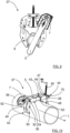
- Figure 2 shows a perspective side view of a cutter clamp 8 that is attached to a pipe 9
- Figure 3 shows a top perspective view of a cutter clamp 8
- Figure 4 shows a bottom perspective view of a cutter clamp 8
- Figure 5 shows a side perspective view of a cutter clamp 8 with a guide bar mounted. Due to different perspectives and levels of detailing, all Figures mentioned above do not show all details.
- the cutter clamp 8 comprises a first arcuate arm part 10 and a second arcuate arm part 11, where the arm parts 10, 11 are arcuate such that they are arranged to adjustably embrace and at least partially enclose a major part of a circumference 57 having a center 58.
- the arm parts 10, 11 comprise a corresponding first end 27, 28 and second end 29, 30, where the first ends 27, 28 are arranged to be located closer to the pipe 9 than the second ends 29, 30 when the cutter clamp 8 is attached to a pipe 9.
- the cutter clamp 8 further comprises a first intermediate part 12, a second intermediate part 13 and a locking screw 14, where the intermediate parts 12, 13 connect the arm parts 10, 11, and where the locking screw 14 runs through the intermediate parts 12, 13.
- the first intermediate part 12 is arranged to be located closer to the first ends 27, 28 than the second intermediate part 13.
- the circumference 57 and center 58 are only imaginary and are only shown in Figure 4 ; the circumference 57 can according to some aspects represent an outer circumference of a pipe.
- the arm parts 10, 11 are sandwiched between outer plates 17, 18 of the first intermediate part 12, which outer plates 17, 18 are separated in an extension L, and are connected by a first screw holder 19 that comprises a aperture 20 for receiving the and retaining an end of the locking screw 14 in a rotatable manner, and two connecting hollow rods; a first connecting hollow rod 21 and a second connecting hollow rod 22 that run mutually parallel along the extension L.
- the first arm part 10 comprises a first elongated slot 15 and the second arm part 11 comprises a second elongated slot 16, where the first hollow rod 21 runs through the first elongated slot 15 and the second hollow rod 22 runs through the second elongated slot 16.
- the arm parts 10, 11 are also sandwiched between outer plates 23, 24 of the second intermediate part 13, which outer plates 23, 24 are separated in the extension L and are connected by a second screw holder 25 and connecting rods, a first connecting rod 31 and a second connecting rod 32.
- the second screw holder 25 comprises a threaded aperture 26 for receiving the locking screw 14, and the connecting rods 31, 32 connect the arm parts 10, 11 in a pivoting manner.
- the cutter clamp 8 is arranged to contact a pipe by means of contact rods 33, 34 attached to the first ends 27, 28 of the arm parts 10, 11 and by means of a contact plate 35 connected to the outer plates 17, 18 of the first intermediate part 12.
- the chain saw 1 is arranged to be attached to the cutter clamp 8 in such a way that stable and fixed working positions are obtained, enabling a straight cut, as will be described more in detail in the following.
- the chain saw 1 comprises a mounting rod 36 that is arranged to be attached to the cutter clamp 8.
- the cutter clamp 8 is arranged for receiving the mounting rod 36 of a chain saw in one of the connecting hollow rods 21, 22, such that the mounting rod 36 runs through a connecting hollow rod 21, 22, enabling the chain saw to pivot.
- the guide bar 5 and the clutch cover 7 are shown in the Figures, not the whole chain saw 1, even if the chain saw is to be understood to be present in its entirety.
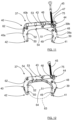
- the hollow rods 21, 22 here constitute attachment points, and in this example, as illustrated for two different pipe dimensions in Figure 6 and Figure 7 , the attachment points 21, 22 move since the hollow rods 21, 22 slide in the elongated slots 15, 16.
- the attachment points 21, 22 have been brought to a position in the elongated slots 15, 16 where the contact surface 35 is brought farther from the contact rods 33, 34 than when a smaller pipe dimension is used, as illustrated in Figure 7 .
- the attachment points 21, 22 and the contact surface 35 adjusts to the current pipe dimension in an automatic manner.
- a shorter guide bar can be used, resulting in a saw that is easier to handle and where the risk of kick-back of the guide bar is reduced, having an enhanced cutting angle.
- a shorter guide bar is enabled since the guide bar 5 always is relatively close to the pipe that is to be cut due to the fact that the attachment points 21, 22 and the contact surface 35 adjusts to the current pipe dimension as described above.
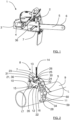
- the arcuate arm parts 10, 11 are in the above each constituted by two arm plates 10a, 10b; 11a, 11b that are separated along the extension L, as in particular shown in Figure 3 and Figure 4 , and are held in positions by means of the the contact rods 33, 34 and additional arm plate holders 59, 60 as illustrated in Figure 1 and Figure 5 .
- the arcuate arm parts may of course be made in many other ways, for example in one piece of material.
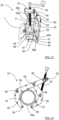
- Figure 10 shows a perspective side view of a cutter clamp 37 that is attached to a pipe 38
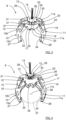
- Figure 11 shows a top perspective view of a cutter clamp 37
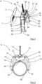
- Figure 12 shows a bottom perspective view of a cutter clamp 37
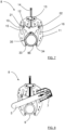
- Figure 13 shows a side perspective view of a cutter clamp 37 with a guide bar mounted. Due to different perspectives and levels of detailing, all Figures mentioned above do not show all details.
- the cutter clamp 37 comprises a first arcuate arm part 39, a second arcuate arm part 40 and a locking screw 45, where the arm parts 39, 40 are arcuate such that they are arranged to adjustably embrace and at least partially enclose a major part of a circumference 63 having a center 64.
- the arm parts 39, 40 comprise a corresponding first end 41, 42 and second end 43, 44, where a first arm second end 43 is attached to the second arm 40 in a pivoting manner by means of an arm attachment rod 53 between a second arm first end 42 and a second arm second end 44.
- the second arm part 40 comprises a first screw holder in the form of a pivoting rod 46 that in turn comprises a threaded aperture 47 arranged for receiving the locking screw 45, where the pivoting rod 46 is positioned between the first arm second end 43 and the second arm second end 44.
- the first arm part 39 comprises a hollow pivoting rod 48 that in turn is attached to a second screw holder 61 adapted for receiving and retaining an end of the locking screw 45 in a rotatable manner.
- the circumference 63 and center 64 are only imaginary and are only shown in Figure 12 ; the circumference 63 can according to some aspects represent an outer circumference of a pipe.
- the cutter clamp 37 is arranged to contact a pipe by means of outer contact rods 49, 50 attached to the first ends 41, 42 of the arm parts 39, 40, or intermediate contact rods 51, 52.
- the intermediate contact rods 51, 52 are attached between the first ends 41, 42 of the arm parts 39, 40 and the arm attachment rod 53.
- the cutter clamp 37 is according to some aspects arranged to contact a pipe by means of means of contact teeth 54 comprised in the second arm part 40.
- the second arm part 40 comprises a hollow rod 62 that runs parallel to the hollow pivoting rod 48 of the first arm part 39, both hollow rods extending along the extension L.
- the cutter clamp 37 is in accordance with the present disclosure arranged for receiving the mounting rod 36 of a chain saw in one of the hollow rods 48, 62, such that the mounting rod 36 runs through a hollow rod 48, 62, enabling the guide bar 5 to pivot.
- the guide bar 5 and the clutch cover 7 are shown, not the whole chain saw 1, even if the chain saw is to be understood to be present in its entirety.
- the the hollow rods 48, 62 here constitute attachment points, and in this example, as discussed above, the attachment points 48, 62 move since the arm parts 39, 40 are tightened against each other for the first direction of rotation of the locking screw 45.
- Each hollow rod 48, 62 moves relative the opposite arm part 39, 40 when the arms parts 39, 40 are adjusted.
- the arcuate arm parts 39, 40 are in the above each constituted by two arm plates 39a, 39b; 40a, 40b that are separated along the extension L, as in particular shown in Figure 11 and Figure 13 , and are held in positions by means of the the contact rods 49, 50; 51, 52 and additional arm plate holders 65, 66, 67 as illustrated in Figure 13 .
- the arcuate arm parts may of course be made in many other ways, for example in one piece of material.
- the cutter clamp 8, 37 comprises a first arm part 10, 39 and a second arm part 11, 40, where the arm parts 10, 11; 39 40 are arcuate and arranged to adjustably at least partially enclose a major part of a circumference 57, 63 having a center 58, 64.
- the adjustment of the arms is performed by means of a locking screw 14, 45.
- the cutter clamp 8, 37 comprises two hollow rods 21, 22; 48, 62, one arranged at each arm part 10, 11; 39, 40, where the hollow rods 21, 22; 48, 62 are arranged for receiving a mounting rod 36 of a power cutter in a pivoting manner.
- the cutter clamp has been shown to comprise two hollow rods 21, 22; 48, 62, but of course there may be only one such hollow rod arranged at one of the arcuate arms, or even more.
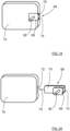
- the mounting rod 36 is attached to a rod attachment device 68 which in turn comprises a first leg part 69 and a second leg part 70 which are separated by an intermediate part 74.
- the clutch cover 7a here comprises a first indentation 71 and a second indentation 72, her in the form of millings, where the indentations 71, 72 are positioned on opposite sides of the clutch cover 7a and are adapted to receive the corresponding leg parts 69, 70 when these are slid into the indentations 71, 72 along a mounting direction 73.
- leg parts 69, 70 have a tight fitting in the indentations 71, 72
- the attachment device 68 can be rigidly fastened to the clutch cover 7a as shown in Figure 20 .
- the leg parts 69, 70 are shown to be of different lengths along the mounting direction 73, where the indentations 71, 72 suitably have corresponding lengths.
- the lengths of the leg parts 69, 70 can of course have any suitable relations, according to some aspects the leg parts 69, 70 have the same length.
- the rod attachment device 68 is according to some aspects suitable for attaching other types of mounting rods, or any types of suitable mounting parts, to a power cutter.
- the rod attachment device 68 is therefore generally constituted by an attachment device 68, and suitable mounting parts are according to some aspects adapted to be fastened to a wall-mounted saw holder.
- Each indentations 71, 72 is according to some aspects constituted by any form of suitable leg holding arrangement. Screws, spring-loaded balls or similar are according to some aspects arranged in at least one leg holding arrangement for securing the corresponding leg part.
- a cutter clamp according to the present disclosure can also be used for a ring saw 56.
- a holding frame 76 according to a first example is attached to the ring saw 56.
- the holding frame 76 comprises a first leg part 81 and a second leg part 82 which are separated by an intermediate part 83.
- the leg parts 81, 82 are fastened to the ring saw 56 by means of suitable fastening means 84 on opposite sides of the ring saw 56 with respect to a cutting plane of a ring saw blade 85.
- the holding frame 76 comprises an attachment flange 78 that is attached to the first leg part 81 and is arranged for releasably attaching a mounting rod 77 to the holding frame 76.
- the mounting rod 77 is in turn adapted to be received by a hollow rod 21, 22; 48, 62 of a cutter clamp 8, 37 according to the above.
- the mounting rod 77 has a treaded end 79, and the attachment flange 78 comprises corresponding inner threads 80.
- Other types of attachments are also conceivable, such as for example welding, press-fit or one or more spring-loaded balls.
- the attachment flange 78 of the holding frame 76 is according to some aspects releasably attachable to other items, such as a previously known wall-mounted saw holding device.
- FIG. 22 there is an alternative holding frame 76a according to a second example where a mounting rod 77a is directly attached to the first leg part 81 in a fixed manner.
- the mounting rod 77a is according to some aspects comprised in an extended intermediate part 83 that protrudes via the first leg part 81.
- the second arm part 40 of the cutter clamp 37 comprises a further hollow rod 75 positioned between the first screw holder 46 and the second arm second end 44.
- This further hollow rod 75 can also be adapted for receiving a mounting rod 36 of a power cutter in a pivoting manner.
- This further hollow rod 75 is especially suitable for receiving a mounting rod of a ring saw according to the above.
- Such a cutter clamp is evidently versatile and possible to use for different types of power cutters.
- an alternative cutter clamp 37' is shown.
- alternative arm parts 39', 40' are shown, where only the hollow rod 75 is comprised in the cutter clamp 37'.
- No other hollow rod that is adapted for receiving a mounting rod 36 of a power cutter in a pivoting manner is comprised in the cutter clamp 37'.
- This cutter clamp 37' is especially suitable for a ring saw according to the above.
- the cutter clamp 37' comprises a locking screw 45 that is rotatably attached to a first screw holder 46 and is arranged to engage threads comprised in a second screw holder 61' such that turning the locking screw enables the adjustment of the arm parts 39', 40'.
- the arm parts 39', 40' comprise a corresponding first end 41', 42' and second end 43', 44', where a first arm second end 43' is attached to the second arm 40' in a pivoting manner by means of an arm attachment rod 53 between a second arm first end 42' and a second arm second end 44'.
- the hollow rod 75 is positioned between the first screw holder 46 and the second arm second end 44'.
- the second screw holder 61' is concealed in Figure 23 , see the second screw holder 61 in Figure 13 for an example of the second screw holder 61' in this example. Since there is no hollow pivoting rod to which the second screw holder 61' is attached, other means are conceivable for attaching the second screw holder 61'.
- an attachment rod 86 is shown to be comprised in the first arm part 39' and adapted for being attached to the second screw holder 61' in a manner similar to the one described with reference to Figure 13 , but other alternatives are of course conceivable.
- an alternative cutter clamp 37" is shown.
- an alternative second arm part 40" is shown without contact teeth.
- the cutter clamp 8, 37 is not only suitable for a chain saw or ring saw, but also other types of power cutters that are suitable for cutting pipes are suitable for attachment to a cutter clamp 8, 37 according to the present disclosure.
- the same cutter clamp 8, 37 can according to some aspects be used for both a chain saw and a ring saw 56 as well as for other types of power cutters.
- the cutter clamp 8, 37 may be made in any suitable material, where the arm parts for example can be made of metal plates, molded metal or molded plastic.
- the intermediate parts 12, 13 that connect the arm parts 10, 11 in the first example can be formed in many ways, there do not to have to be any outer plates.
- one intermediate part 12 comprises the first screw holder 19 and the hollow rods 21, 22, while the other intermediate part 13 comprises the second screw holder 25.
- the hollow rods 21, 22 move relative the rest of the cutter clamp 8 and the pipe 9 that is to be retained by means of the elongated slots 15, 16 formed in the arm parts.
- the cutter clamps 8, 37, 37', 37" described are not only suitable when cutting through pipes, but many other items can easily be cut with the help of a cutter clamp 8, 37, 37', 37" according to the present disclosure.
- the chain saw 1 comprises a motor 2 which can be constituted by a combustion engine or an electric motor.
Landscapes
- Engineering & Computer Science (AREA)
- Mechanical Engineering (AREA)
- Life Sciences & Earth Sciences (AREA)
- Physics & Mathematics (AREA)
- Optics & Photonics (AREA)
- Wood Science & Technology (AREA)
- Forests & Forestry (AREA)
- Mining & Mineral Resources (AREA)
- Sawing (AREA)
Claims (16)
- Schneidklemme (37, 37', 37"), die einen ersten Armteil (39, 39') und einen zweiten Armteil (40, 40', 40") umfasst, wobei die Armteile (39, 40; 39', 40', 40") bogenförmig sind und angeordnet sind, um einen größeren Teil eines Umfangs (63), der einen Mittelpunkt (64) aufweist, einstellbar mindestens teilweise zu umschließen, wobei die Schneidklemme (37, 37', 37") mindestens eine hohle Stange (48, 62, 75) umfasst, die zum Aufnehmen einer Montagestange (36, 77, 77a) einer elektrischen Schneideinrichtung (1, 56) in einer schwenkenden Weise angeordnet ist, wobei die Armteile (39, 40, 39', 40', 40") ein entsprechendes erstes Ende (41, 42, 41', 42') und ein zweites Ende (43, 44, 43', 44') umfassen, wobei ein zweites Ende (43, 43') des ersten Arms an dem zweiten Arm (40, 40', 40") in einer schwenkenden Weise mittels einer Armbefestigungsstange (53) zwischen einem ersten Ende (42, 42') des zweiten Arms und einem zweiten Ende (44, 44') des zweiten Arms befestigt ist, wobei der zweite Armteil (40, 40', 40") einen ersten Schraubenhalter in der Form einer Schwenkstange (46) umfasst, die zwischen dem zweiten Ende (43, 43') des ersten Arms und dem zweiten Ende (44, 44') des zweiten Arms positioniert ist, wobei- je kleiner der Umfang, auf den die Armteile (39, 40, 40") angepasst sind, desto näher wird die hohle Stange (48, 62) zu dem Mittelpunkt (64) bewegt, und der zweite Armteil (40, 40', 40") eine weitere hohle Stange (75) umfasst, die zwischen dem ersten Schraubenhalter (46) und dem zweiten Ende des zweiten Arms (44, 44') positioniert ist, oder- der zweite Armteil (40, 40', 40") nur eine hohle Stange (75) umfasst, die zwischen dem ersten Schraubenhalter (46) und dem zweiten Ende (44, 44') des zweiten Arms positioniert ist.
- Schneidklemme (37, 37', 37") nach einem der vorstehenden Ansprüche, wobei die Schneidklemme (37, 37') eine Feststellschraube (45) umfasst, die an dem ersten Schraubenhalter (46) drehbar befestigt ist und angeordnet ist, um Gewinde in Eingriff zu bringen, die in einem zweiten Schraubenhalter (61, 61') derart enthalten sind, dass ein Drehen der Feststellschraube die Einstellung der Armteile (39, 40; 39', 40') ermöglicht.
- Schneidklemme (37, 37") nach Anspruch 2, wobei der zweite Armteil (40, 40") den ersten Schraubenhalter (46) umfasst, der zwischen dem zweiten Ende (43) des ersten Arms und dem zweiten Ende (44) des zweiten Arms positioniert ist, wobei der erste Armteil (39) eine hohle Schwenkstange (48) umfasst, die wiederum an dem zweiten Schraubenhalter (61) befestigt ist.
- Schneidklemme (37, 37") nach Anspruch 3, wobei jede hohle Stange (48, 62) an einem entsprechenden Armteil (39, 40, 40") derart befestigt ist, dass, wenn die Armteile (39, 40, 40") eingestellt sind, die hohle Stange (48, 62) sich relativ zu dem gegenüberliegenden Armteil (39, 40, 40") bewegt.
- Schneidklemme (37, 37', 37") nach einem der vorstehenden Ansprüche, wobei der zweite Armteil (40, 40', 40") eine weitere hohle Stange (75) umfasst, die zwischen dem ersten Schraubenhalter (46) und dem zweiten Ende (44, 44') des zweiten Arms positioniert ist.
- Schneidklemme (37, 37', 37"), die einen ersten Armteil (39, 39') und einen zweiten Armteil (40, 40', 40") umfasst, wobei die Armteile (39, 40; 39', 40', 40") bogenförmig sind und angeordnet sind, um einen größeren Teil eines Umfangs (63), der einen Mittelpunkt (64) aufweist, einstellbar mindestens teilweise zu umschließen, wobei die Schneidklemme (37, 37', 37") eine hohle Stange (75) umfasst, die angeordnet ist, um eine Montagestange (36) einer elektrischen Schneideinrichtung (1, 56) in einer schwenkenden Weise aufzunehmen, wobei die Schneidklemme (37, 37', 37") eine Feststellschraube (45) umfasst, die an einem ersten Schraubenhalter (46) drehbar befestigt ist und angeordnet ist, um Gewinde in Eingriff zu bringen, die in einem zweiten Schraubenhalter (61, 61') derart enthalten sind, dass das Drehen der Feststellschraube die Einstellung der Armteile (39, 40; 39', 40', 40") ermöglicht, wobei die Armteile (39, 40; 39', 40', 40") ein entsprechendes erstes Ende (41, 42; 41', 42') und ein zweites Ende (43, 44; 43', 44') umfassen, wobei ein zweites Ende (43, 43') des ersten Arms in einer schwenkenden Weise mittels einer Armbefestigungsstange (53) zwischen einem ersten Ende (42, 42') des zweiten Arms und einem zweiten Ende (44, 44') des zweiten Arms an dem zweiten Arm (40, 40') befestigt ist, wobei die hohle Stange(75) zwischen dem ersten Schraubenhalter (46) und dem zweiten Ende (44, 44') des zweiten Arms positioniert ist.
- Schneidklemme (37') nach Anspruch 6, wobei der zweite Armteil (40') den ersten Schraubenhalter (46') umfasst, der zwischen dem zweiten Ende (43') des ersten Arms und dem zweiten Ende (44') des zweiten Arms positioniert ist, wobei der erste Armteil (39') eine Befestigungsstange (86) umfasst, die an dem zweiten Schraubenhalter (61') befestigt ist.
- Schneidklemme (37, 37') nach einem der Ansprüche 6 oder 7, wobei der zweite Armteil (40, 40') Kontaktzähne (54) umfasst, die angeordnet sind, um ein Rohr zu kontaktieren.
- Schneidklemme (8), die einen ersten Armteil (10) und einen zweiten Armteil (11) umfasst, wobei die Armteile (10, 11) bogenförmig sind und angeordnet sind, um einen größeren Teil eines Umfangs (57) mit einem Mittelpunkt (58) einstellbar mindestens teilweise zu umschließen, wobei die Schneidklemme (8) mindestens eine hohle Stange (21, 22) umfasst, die zum Aufnehmen einer Montagestange (36) einer elektrischen Schneideinrichtung (1, 56) in einer schwenkenden Weise angeordnet ist, wobei je kleiner der Umfang, auf den die Armteile (10, 11) eingestellt sind, desto näher wird die hohle Stange (21, 22) zu dem Mittelpunkt (58) bewegt wird, wobei die Schneidklemme (8) einen ersten Zwischenteil (12) und einen zweiten Zwischenteil (13) umfasst, wobei die Zwischenteile (12, 13) die Armteile (10, 11) verbinden, und wobei eine Feststellschraube (14) mindestens teilweise über die Zwischenteile (12, 13) verläuft, und wenn die Armteile (10, 11) eingestellt werden, sich jede hohle Stange (21, 22) relativ zu den Armteilen (10, 11) durch Gleiten in einem entsprechenden länglichen Schlitz (15, 16) erstreckt, der in einem entsprechenden Armteil (10, 11) ausgebildet ist.
- Schneidklemme (8) nach Anspruch 9, wobei die Schneidklemme (8) eine Feststellschraube (14) umfasst, die an einem ersten Schraubenhalter (19) drehbar befestigt ist und angeordnet ist, um Gewinde in Eingriff zu bringen, die in einem zweiten Schraubenhalter (25) derart enthalten sind, dass das Drehen der Feststellschraube die Einstellung der Armteile (10, 11) ermöglicht.
- Schneidklemme (8) nach Anspruch 10, wobei ein Zwischenteil (12) den ersten Schraubenhalter (19) und die hohle Stange (21, 22) umfasst, während das andere Zwischenteil (13) den zweiten Schraubenhalter (25) umfasst.
- Schneidklemmensatz, wobei der Schneidklemmensatz eine Schneidklemme (8, 37, 37', 37") nach einem der Ansprüche 1 bis 12, eine Kraftübertragungsabdeckung (7a, 7b) und eine Befestigungsvorrichtung (68) umfasst, die zum Befestigen eines Montageteils (36) an einer Kraftübertragungsabdeckung (7a, 7b) für eine elektrische Schneideinrichtung (1) angepasst ist, wobei die Befestigungsvorrichtung (68) einen ersten Beinteil (69) und einen zweiten Beinteil (70) umfasst, wobei die Beinteile (69, 70) durch ein Zwischenteil (74) getrennt sind, wobei das Montageteil (36) an dem ersten Beinteil (69) befestigt ist, wobei ferner die Beinteile (69, 70) angepasst sind, um auf gegenüberliegenden Seiten der Kraftübertragungsabdeckung (7a, 7b) derart positioniert zu werden, dass mindestens ein Beinteil (69, 70) durch eine entsprechende Beinhalteanordnung (71, 72) aufgenommen und gehalten wird.
- Schneidklemmensatz nach Anspruch 12, wobei das Montageteil (36) aus einer Montagestange besteht, die angepasst ist, um mit einer Schneidklemme (8, 37, 37', 37") nach einem der Ansprüche 1 bis 12 verbunden zu werden.
- Schneidklemmen- und Halterahmensystem, umfassend eine Schneidklemme (8, 37, 37', 37") nach einem der Ansprüche 1 bis 11 und einen Halterahmen (76), der angepasst ist, um an einer Ringsäge (56) befestigt zu werden, wobei der Halterahmen (76) einen ersten Beinteil (81) und einen zweiten Beinteil (82) umfasst, wobei die Beinteile (81, 82) durch einen Zwischenteil (83) getrennt sind, wobei die Beinteile (81, 82) angepasst sind, um an einer Ringsäge (56) auf gegenüberliegenden Seiten der Ringsäge (56) in Bezug auf eine Schnittebene eines Ringsägeblattes (85) befestigt zu werden, wobei der Halterahmen (76) einen Befestigungsflansch (78) umfasst, der an dem ersten Beinteil (81) befestigt ist, wobei der Befestigungsflansch (78) angeordnet ist, um an einer Montagestange (77) lösbar befestigt zu werden, die angepasst ist, um mit der Schneidklemme (8, 37, 37', 37") verbunden zu werden.
- Schneidklemmen- und Halterahmensystem nach Anspruch 14, wobei die Montagestange (77) ein Gewindeende (79) aufweist und der Befestigungsflansch (78) entsprechende Innengewinde (80) umfasst.
- Schneidklemmen- und Halterahmensystem, umfassend eine Schneidklemme (8, 37, 37', 37") nach einem der Ansprüche 1 bis 11 und einen Halterahmen (76a), der angepasst ist, um an einer Ringsäge (56) befestigt zu werden, wobei der Halterahmen (76a) einen ersten Beinteil (81) und einen zweiten Beinteil (82) umfasst, wobei die Beinteile (81, 82) durch einen Zwischenteil (83) getrennt sind, wobei die Beinteile (81, 82) angepasst sind, um an einer Ringsäge (56) auf gegenüberliegenden Seiten der Ringsäge (56) in Bezug auf eine Schnittebene eines Ringsägeblattes (85) angebracht zu werden, wobei der Halterahmen (76a) eine Montagestange (77a) umfasst, die an dem ersten Beinteil (81) direkt und fest befestigt ist, wobei die Montagestange (77a) angepasst ist, um mit der Schneidklemme (8, 37, 37', 37") verbunden zu werden.
Applications Claiming Priority (2)
| Application Number | Priority Date | Filing Date | Title |
|---|---|---|---|
| SE1751027A SE541669C2 (en) | 2017-08-28 | 2017-08-28 | A cutter clamp |
| PCT/SE2018/050449 WO2019045614A1 (en) | 2017-08-28 | 2018-05-02 | CUTTER CLAMP, ATTACHMENT DEVICE, CUTTING CLAMP SET, AND HOLDING BODY |
Publications (3)
| Publication Number | Publication Date |
|---|---|
| EP3676037A1 EP3676037A1 (de) | 2020-07-08 |
| EP3676037A4 EP3676037A4 (de) | 2021-08-04 |
| EP3676037B1 true EP3676037B1 (de) | 2024-10-02 |
Family
ID=65525799
Family Applications (1)
| Application Number | Title | Priority Date | Filing Date |
|---|---|---|---|
| EP18851371.7A Active EP3676037B1 (de) | 2017-08-28 | 2018-05-02 | Schneiderklemmen, schneiderklemmen-kit und schneiderklemmen- und halterahmensysteme |
Country Status (4)
| Country | Link |
|---|---|
| US (1) | US11305405B2 (de) |
| EP (1) | EP3676037B1 (de) |
| SE (1) | SE541669C2 (de) |
| WO (1) | WO2019045614A1 (de) |
Families Citing this family (10)
| Publication number | Priority date | Publication date | Assignee | Title |
|---|---|---|---|---|
| SE541669C2 (en) * | 2017-08-28 | 2019-11-26 | Husqvarna Ab | A cutter clamp |
| CN110315126B (zh) * | 2019-06-25 | 2020-06-26 | 湖州银都铝业有限公司 | 一种铝型材制备用切割机 |
| CN110450116B (zh) * | 2019-07-10 | 2020-12-11 | 浙江海州宝实业有限公司 | 一种五金管材加工用装夹台 |
| DE102019121096A1 (de) * | 2019-08-05 | 2021-02-11 | Mafell Ag | Tragbare Einklemmvorrichtung und Elektrowerkzeug mit integrierter Werkstückfixierung |
| CN111604541B (zh) * | 2020-04-30 | 2021-05-14 | 张家港幸运金属工艺品有限公司 | 一种金属加工用切割装置 |
| CN111390275A (zh) * | 2020-05-11 | 2020-07-10 | 郑荣城 | 一种高精度铝型材切割装置及其使用方法 |
| CN113601217B (zh) * | 2021-07-20 | 2022-06-28 | 青岛理工大学 | 一种汽车轮毂夹具、加工设备及生产线 |
| AU2022368460B2 (en) | 2021-10-22 | 2025-10-16 | Ring Rescue Inc. | Ring cutter for safely transecting a ring trapped on an appendage |
| CN115824302A (zh) * | 2022-11-30 | 2023-03-21 | 西安奕斯伟材料科技有限公司 | 单晶转运测量方法及系统 |
| USD1089340S1 (en) | 2023-06-22 | 2025-08-19 | Ring Rescue Inc. | Ring cutter |
Family Cites Families (54)
| Publication number | Priority date | Publication date | Assignee | Title |
|---|---|---|---|---|
| US1086574A (en) | 1914-02-10 | Anton Anderson | Clamp. | |
| US1075384A (en) | 1913-05-13 | 1913-10-14 | Emil K F Seidel | Woodworking-clamp. |
| DE495132C (de) | 1929-05-02 | 1930-04-02 | Ernst A Rueeger | Transportable Stamm- und Ablaeng-Kettensaege |
| US2567833A (en) | 1948-09-04 | 1951-09-11 | Chester E Warren | Pipe cutter |
| US2890906A (en) * | 1954-08-04 | 1959-06-16 | Jones & Laughlin Steel Corp | Article lifting apparatus |
| US2870536A (en) | 1957-08-26 | 1959-01-27 | Lutsker Simon | Tubing cutter |
| FR2267418B1 (de) * | 1974-04-09 | 1976-10-08 | Mecanique Ste Turripinoise | |
| US4068415A (en) * | 1976-01-12 | 1978-01-17 | Racine Railroad Products, Inc. | Rail cutting apparatus |
| US4156991A (en) * | 1978-01-09 | 1979-06-05 | Racine Railroad Products, Inc. | Rail cutting apparatus |
| US4278246A (en) * | 1979-12-13 | 1981-07-14 | Blake John B | Clamping device |
| CH639588A5 (en) | 1980-04-09 | 1983-11-30 | Walter Oetliker | Holder for a power chain-saw with a pivotable protective hood |
| NO147370C (no) | 1981-03-26 | 1983-03-30 | Norcem As | Tilleggsutstyr til motordrevet kjedesag. |
| US4476759A (en) * | 1982-03-03 | 1984-10-16 | Aderneck Stephen E | Portable chainsaw milling guide attachment |
| DE3521697A1 (de) * | 1984-06-18 | 1986-02-20 | Tetsushi Ichihara Chiba Kubo | Rohrbearbeitungsvorrichtung |
| JPS6131613U (ja) | 1984-07-30 | 1986-02-26 | 勝 北井 | カツタ−支持装置 |
| JPS6165718A (ja) * | 1984-09-07 | 1986-04-04 | Kusumoto Kazushige | フレキシブルシヤフトの切断鋸による水道管等の切断方法 |
| US4689883A (en) | 1985-11-04 | 1987-09-01 | Dent Larry G | Pipe cutting device |
| US4682919A (en) | 1986-05-05 | 1987-07-28 | Reed Manufacturing Company | Portable powered pipe working machine |
| GB8925104D0 (en) | 1989-11-07 | 1989-12-28 | British Gas Plc | Cutting apparatus |
| US5107594A (en) * | 1991-09-03 | 1992-04-28 | Julian Ferreras | Piling cutting tool |
| RU1838054C (ru) | 1992-02-05 | 1993-08-30 | Mamedov Ilgam I | Устройство дл резки труб |
| SE506306C2 (sv) * | 1993-05-03 | 1997-12-01 | Electrolux Ab | Anordning vid kapmaskin eller cirkelsåg samt ett system med ett flertal utbytbara komponenter |
| DE9417353U1 (de) | 1994-10-28 | 1995-01-26 | Ludwig Hunger Maschinenfabrik GmbH, 86916 Kaufering | Klemmvorrichtung |
| DE19614611C2 (de) | 1996-04-15 | 2001-01-11 | Spitznas Maschinenfabrik Gmbh | Rohrtrennvorrichtung |
| FI990167A7 (fi) | 1999-01-29 | 2000-07-30 | For Man Trade Oy | Laite putkimaisten tai pyörötankomaisten kappaleiden työstämistä tai käsittelemistä varten |
| FI108927B (fi) | 2000-06-30 | 2002-04-30 | For Man Trade Oy | Laite putkimaisten tai pyörötankomaisten kappaleiden työstämistä, erityisesti katkaisemista varten |
| EP1810800B1 (de) | 2001-03-02 | 2009-01-21 | Landrock GmbH | Verfahren zum Ablängen von gebündelten Holzstücken zu Stückholz |
| DE10229671A1 (de) | 2001-07-04 | 2003-01-23 | Klaus Fritsch | Haltevorrichtung für Motorsäge, insbesondere für Kettensäge |
| US6619171B2 (en) | 2002-01-09 | 2003-09-16 | Blount, Inc. | Guide bar for tree harvesting including stump treatment |
| FI118076B (fi) | 2003-05-22 | 2007-06-29 | Exact Tools Oy | Laite putkimaisten ja pyörötankomaisten kappaleiden työstämistä, erityisesti katkaisemista varten |
| US6893012B2 (en) * | 2003-05-23 | 2005-05-17 | Valtra, Inc. | Quick release cantilever clamp |
| CA2542630A1 (en) * | 2006-04-10 | 2007-10-10 | Enbridge Gas Distribution Inc. | Service tee cutting apparatus and abandonment method |
| US7703211B1 (en) * | 2007-06-04 | 2010-04-27 | Kirchhoff Robert W | Easy lift saw platform |
| AT505753B1 (de) | 2007-10-22 | 2009-04-15 | Reichart Ing Otto | Motorsage |
| DE102008025716A1 (de) * | 2008-05-29 | 2009-12-03 | Illinois Tool Works Inc., Glenview | Rohrbearbeitungsvorrichtung, insbesondere Rohrtrennvorrichtung |
| US8651005B2 (en) * | 2008-07-09 | 2014-02-18 | Blount, Inc. | Utility chain cutter |
| CN101758294B (zh) * | 2008-12-25 | 2012-03-28 | 苏州宝时得电动工具有限公司 | 往复锯 |
| DE202009014060U1 (de) | 2009-10-14 | 2010-02-11 | Henkel, Meinolf | Kettensägebock |
| WO2011067262A1 (en) * | 2009-12-03 | 2011-06-09 | Cembre S.P.A. | Apparatus for the tooling of a workpiece |
| DE202010008463U1 (de) | 2010-09-06 | 2011-12-07 | Industriepartners Gmbh | Vorrichtung zum Durchtrennen eines Rohres |
| US9385911B2 (en) | 2011-05-13 | 2016-07-05 | Sameer Vermani | Systems and methods for wireless communication of packets having a plurality of formats |
| FI123764B (fi) | 2011-07-06 | 2013-10-31 | Exact Tools Oy | Laite putkimaisen kappaleen työstämiseksi |
| DE102011080450A1 (de) | 2011-08-04 | 2013-02-07 | WIDOS Wilhelm Dommer Söhne GmbH | Vorrichtung zum Schneiden von großvolumigen Kunststoffrohren |
| US8720070B2 (en) | 2011-11-04 | 2014-05-13 | Reed Manufacturing Company | Pipe peeler |
| CA2854721C (en) * | 2011-11-09 | 2017-07-04 | Sumner Manufacturing Co.,Inc. | Clamp assembly |
| WO2014007701A1 (en) | 2012-07-04 | 2014-01-09 | Iggesund Forest Ab | Cutting arrangement for gripping and cutting trees or bushes |
| DE102013101046A1 (de) | 2013-02-01 | 2014-08-07 | Alexander van Linn | Vorrichtung zum Bearbeiten eines Holzbündels mit mindestens einer Sägevorrichtung geeignet zur Schneidholzherstellung |
| FI125718B (en) | 2014-01-22 | 2016-01-29 | Exact Tools Oy | A device for treating a tubular or rotary bar |
| DE102014006255A1 (de) | 2014-04-28 | 2015-10-29 | PF Schweißtechnologie GmbH | Bearbeitungsvorrichtung für Rohrmantelflächen |
| WO2016012776A1 (en) | 2014-07-22 | 2016-01-28 | Andrew Page | Tree-cutting head |
| US9724808B2 (en) * | 2016-01-05 | 2017-08-08 | William Blackford | Ergonomic front fork service tool |
| FI20165277A (fi) * | 2016-04-01 | 2017-10-02 | Exact Tools Oy | Laite työstöyksikön tukemiseksi kappaleen manipuloimista varten |
| CN107052692A (zh) * | 2016-12-07 | 2017-08-18 | 西北工业大学(张家港)智能装备技术产业化研究院有限公司 | 管道焊接夹具 |
| SE541669C2 (en) * | 2017-08-28 | 2019-11-26 | Husqvarna Ab | A cutter clamp |
-
2017
- 2017-08-28 SE SE1751027A patent/SE541669C2/en unknown
-
2018
- 2018-05-02 WO PCT/SE2018/050449 patent/WO2019045614A1/en not_active Ceased
- 2018-05-02 EP EP18851371.7A patent/EP3676037B1/de active Active
- 2018-05-02 US US16/640,867 patent/US11305405B2/en active Active
Also Published As
| Publication number | Publication date |
|---|---|
| WO2019045614A1 (en) | 2019-03-07 |
| US20200189070A1 (en) | 2020-06-18 |
| SE1751027A1 (en) | 2019-03-01 |
| US11305405B2 (en) | 2022-04-19 |
| EP3676037A4 (de) | 2021-08-04 |
| EP3676037A1 (de) | 2020-07-08 |
| SE541669C2 (en) | 2019-11-26 |
Similar Documents
| Publication | Publication Date | Title |
|---|---|---|
| EP3676037B1 (de) | Schneiderklemmen, schneiderklemmen-kit und schneiderklemmen- und halterahmensysteme | |
| EP2977155B1 (de) | Elektrowerkzeugzubehör mit stütze | |
| US4402136A (en) | Device for cutting pipes | |
| US5806187A (en) | Clamping device | |
| US10945381B1 (en) | Modular tools with detachable coupling | |
| US5611146A (en) | Clamping device for use with a hand-held tool | |
| CA2974671C (en) | Miter saw | |
| US9186767B2 (en) | Knife jig assembly | |
| US2880773A (en) | Hack saw | |
| FR2964526A1 (fr) | Bras porteur d'outils amovibles adaptable sur tondeuse autoportee, microtracteur, chariot elevateur | |
| EP2492070A1 (de) | Kettensäge, insbesondere zum Beschneiden von Bäumen und Büschen | |
| US6942416B2 (en) | Device for attaching a handle | |
| US8181350B1 (en) | Precision cutting system | |
| CN114559098A (zh) | 管切断工具和用于这种工具的附件 | |
| EP3082396B1 (de) | Griffanordnung für ein elektrowerkzeug | |
| EP0032148A4 (de) | Vorrichtung zum schneiden von rohren. | |
| US4461081A (en) | Knife-saw implement | |
| JP2013247888A (ja) | 携帯型作業機 | |
| EP1588817B1 (de) | Anpassung einer Stichsäge zum Schneiden von Nuten in Mauern | |
| CN105309209A (zh) | 一种多自由度绿篱机 | |
| US3115911A (en) | Guide apparatus for hole saws | |
| US20070130782A1 (en) | Saw alignment device, blade assembly, and method for cutting a workpiece | |
| US20170224186A1 (en) | Hand tool with scraper blade | |
| EP3274142B1 (de) | Schneidevorrichtung mit schwenkbarer arbeitsanordnung | |
| EP1085965B1 (de) | Handgriff für tragbares werkzeug |
Legal Events
| Date | Code | Title | Description |
|---|---|---|---|
| STAA | Information on the status of an ep patent application or granted ep patent |
Free format text: STATUS: THE INTERNATIONAL PUBLICATION HAS BEEN MADE |
|
| PUAI | Public reference made under article 153(3) epc to a published international application that has entered the european phase |
Free format text: ORIGINAL CODE: 0009012 |
|
| STAA | Information on the status of an ep patent application or granted ep patent |
Free format text: STATUS: REQUEST FOR EXAMINATION WAS MADE |
|
| 17P | Request for examination filed |
Effective date: 20200309 |
|
| AK | Designated contracting states |
Kind code of ref document: A1 Designated state(s): AL AT BE BG CH CY CZ DE DK EE ES FI FR GB GR HR HU IE IS IT LI LT LU LV MC MK MT NL NO PL PT RO RS SE SI SK SM TR |
|
| AX | Request for extension of the european patent |
Extension state: BA ME |
|
| DAV | Request for validation of the european patent (deleted) | ||
| DAX | Request for extension of the european patent (deleted) | ||
| RIC1 | Information provided on ipc code assigned before grant |
Ipc: B23D 47/04 20060101AFI20210330BHEP Ipc: B23D 21/10 20060101ALI20210330BHEP Ipc: B23D 45/12 20060101ALI20210330BHEP Ipc: B23D 45/16 20060101ALI20210330BHEP Ipc: B23D 51/04 20060101ALI20210330BHEP Ipc: B23K 37/02 20060101ALI20210330BHEP Ipc: B23Q 3/06 20060101ALI20210330BHEP Ipc: B25B 5/14 20060101ALI20210330BHEP Ipc: B25H 1/00 20060101ALI20210330BHEP Ipc: B27B 17/00 20060101ALI20210330BHEP Ipc: B28D 1/00 20060101ALI20210330BHEP |
|
| A4 | Supplementary search report drawn up and despatched |
Effective date: 20210707 |
|
| RIC1 | Information provided on ipc code assigned before grant |
Ipc: B23D 47/04 20060101AFI20210701BHEP Ipc: B23D 21/10 20060101ALI20210701BHEP Ipc: B23D 45/12 20060101ALI20210701BHEP Ipc: B23D 45/16 20060101ALI20210701BHEP Ipc: B23D 51/04 20060101ALI20210701BHEP Ipc: B23K 37/02 20060101ALI20210701BHEP Ipc: B23Q 3/06 20060101ALI20210701BHEP Ipc: B25B 5/14 20060101ALI20210701BHEP Ipc: B25H 1/00 20060101ALI20210701BHEP Ipc: B27B 17/00 20060101ALI20210701BHEP Ipc: B28D 1/00 20060101ALI20210701BHEP |
|
| STAA | Information on the status of an ep patent application or granted ep patent |
Free format text: STATUS: EXAMINATION IS IN PROGRESS |
|
| 17Q | First examination report despatched |
Effective date: 20230303 |
|
| GRAP | Despatch of communication of intention to grant a patent |
Free format text: ORIGINAL CODE: EPIDOSNIGR1 |
|
| STAA | Information on the status of an ep patent application or granted ep patent |
Free format text: STATUS: GRANT OF PATENT IS INTENDED |
|
| INTG | Intention to grant announced |
Effective date: 20231221 |
|
| GRAJ | Information related to disapproval of communication of intention to grant by the applicant or resumption of examination proceedings by the epo deleted |
Free format text: ORIGINAL CODE: EPIDOSDIGR1 |
|
| STAA | Information on the status of an ep patent application or granted ep patent |
Free format text: STATUS: EXAMINATION IS IN PROGRESS |
|
| INTC | Intention to grant announced (deleted) | ||
| GRAP | Despatch of communication of intention to grant a patent |
Free format text: ORIGINAL CODE: EPIDOSNIGR1 |
|
| STAA | Information on the status of an ep patent application or granted ep patent |
Free format text: STATUS: GRANT OF PATENT IS INTENDED |
|
| INTG | Intention to grant announced |
Effective date: 20240613 |
|
| GRAS | Grant fee paid |
Free format text: ORIGINAL CODE: EPIDOSNIGR3 |
|
| GRAA | (expected) grant |
Free format text: ORIGINAL CODE: 0009210 |
|
| STAA | Information on the status of an ep patent application or granted ep patent |
Free format text: STATUS: THE PATENT HAS BEEN GRANTED |
|
| AK | Designated contracting states |
Kind code of ref document: B1 Designated state(s): AL AT BE BG CH CY CZ DE DK EE ES FI FR GB GR HR HU IE IS IT LI LT LU LV MC MK MT NL NO PL PT RO RS SE SI SK SM TR |
|
| REG | Reference to a national code |
Ref country code: GB Ref legal event code: FG4D |
|
| REG | Reference to a national code |
Ref country code: CH Ref legal event code: EP |
|
| P01 | Opt-out of the competence of the unified patent court (upc) registered |
Free format text: CASE NUMBER: APP_52294/2024 Effective date: 20240918 |
|
| REG | Reference to a national code |
Ref country code: IE Ref legal event code: FG4D |
|
| REG | Reference to a national code |
Ref country code: DE Ref legal event code: R096 Ref document number: 602018075043 Country of ref document: DE |
|
| REG | Reference to a national code |
Ref country code: LT Ref legal event code: MG9D |
|
| REG | Reference to a national code |
Ref country code: NL Ref legal event code: MP Effective date: 20241002 |
|
| REG | Reference to a national code |
Ref country code: AT Ref legal event code: MK05 Ref document number: 1728126 Country of ref document: AT Kind code of ref document: T Effective date: 20241002 |
|
| PG25 | Lapsed in a contracting state [announced via postgrant information from national office to epo] |
Ref country code: NL Free format text: LAPSE BECAUSE OF FAILURE TO SUBMIT A TRANSLATION OF THE DESCRIPTION OR TO PAY THE FEE WITHIN THE PRESCRIBED TIME-LIMIT Effective date: 20241002 |
|
| PG25 | Lapsed in a contracting state [announced via postgrant information from national office to epo] |
Ref country code: NL Free format text: LAPSE BECAUSE OF FAILURE TO SUBMIT A TRANSLATION OF THE DESCRIPTION OR TO PAY THE FEE WITHIN THE PRESCRIBED TIME-LIMIT Effective date: 20241002 |
|
| PG25 | Lapsed in a contracting state [announced via postgrant information from national office to epo] |
Ref country code: HR Free format text: LAPSE BECAUSE OF FAILURE TO SUBMIT A TRANSLATION OF THE DESCRIPTION OR TO PAY THE FEE WITHIN THE PRESCRIBED TIME-LIMIT Effective date: 20241002 Ref country code: PT Free format text: LAPSE BECAUSE OF FAILURE TO SUBMIT A TRANSLATION OF THE DESCRIPTION OR TO PAY THE FEE WITHIN THE PRESCRIBED TIME-LIMIT Effective date: 20250203 Ref country code: IS Free format text: LAPSE BECAUSE OF FAILURE TO SUBMIT A TRANSLATION OF THE DESCRIPTION OR TO PAY THE FEE WITHIN THE PRESCRIBED TIME-LIMIT Effective date: 20250202 |
|
| PG25 | Lapsed in a contracting state [announced via postgrant information from national office to epo] |
Ref country code: FI Free format text: LAPSE BECAUSE OF FAILURE TO SUBMIT A TRANSLATION OF THE DESCRIPTION OR TO PAY THE FEE WITHIN THE PRESCRIBED TIME-LIMIT Effective date: 20241002 |
|
| PG25 | Lapsed in a contracting state [announced via postgrant information from national office to epo] |
Ref country code: BG Free format text: LAPSE BECAUSE OF FAILURE TO SUBMIT A TRANSLATION OF THE DESCRIPTION OR TO PAY THE FEE WITHIN THE PRESCRIBED TIME-LIMIT Effective date: 20241002 |
|
| PG25 | Lapsed in a contracting state [announced via postgrant information from national office to epo] |
Ref country code: ES Free format text: LAPSE BECAUSE OF FAILURE TO SUBMIT A TRANSLATION OF THE DESCRIPTION OR TO PAY THE FEE WITHIN THE PRESCRIBED TIME-LIMIT Effective date: 20241002 |
|
| PG25 | Lapsed in a contracting state [announced via postgrant information from national office to epo] |
Ref country code: NO Free format text: LAPSE BECAUSE OF FAILURE TO SUBMIT A TRANSLATION OF THE DESCRIPTION OR TO PAY THE FEE WITHIN THE PRESCRIBED TIME-LIMIT Effective date: 20250102 |
|
| PG25 | Lapsed in a contracting state [announced via postgrant information from national office to epo] |
Ref country code: AT Free format text: LAPSE BECAUSE OF FAILURE TO SUBMIT A TRANSLATION OF THE DESCRIPTION OR TO PAY THE FEE WITHIN THE PRESCRIBED TIME-LIMIT Effective date: 20241002 Ref country code: LV Free format text: LAPSE BECAUSE OF FAILURE TO SUBMIT A TRANSLATION OF THE DESCRIPTION OR TO PAY THE FEE WITHIN THE PRESCRIBED TIME-LIMIT Effective date: 20241002 Ref country code: GR Free format text: LAPSE BECAUSE OF FAILURE TO SUBMIT A TRANSLATION OF THE DESCRIPTION OR TO PAY THE FEE WITHIN THE PRESCRIBED TIME-LIMIT Effective date: 20250103 |
|
| PG25 | Lapsed in a contracting state [announced via postgrant information from national office to epo] |
Ref country code: CZ Free format text: LAPSE BECAUSE OF FAILURE TO SUBMIT A TRANSLATION OF THE DESCRIPTION OR TO PAY THE FEE WITHIN THE PRESCRIBED TIME-LIMIT Effective date: 20241002 Ref country code: PL Free format text: LAPSE BECAUSE OF FAILURE TO SUBMIT A TRANSLATION OF THE DESCRIPTION OR TO PAY THE FEE WITHIN THE PRESCRIBED TIME-LIMIT Effective date: 20241002 |
|
| PG25 | Lapsed in a contracting state [announced via postgrant information from national office to epo] |
Ref country code: RS Free format text: LAPSE BECAUSE OF FAILURE TO SUBMIT A TRANSLATION OF THE DESCRIPTION OR TO PAY THE FEE WITHIN THE PRESCRIBED TIME-LIMIT Effective date: 20250102 |
|
| PG25 | Lapsed in a contracting state [announced via postgrant information from national office to epo] |
Ref country code: SM Free format text: LAPSE BECAUSE OF FAILURE TO SUBMIT A TRANSLATION OF THE DESCRIPTION OR TO PAY THE FEE WITHIN THE PRESCRIBED TIME-LIMIT Effective date: 20241002 |
|
| REG | Reference to a national code |
Ref country code: DE Ref legal event code: R097 Ref document number: 602018075043 Country of ref document: DE |
|
| PG25 | Lapsed in a contracting state [announced via postgrant information from national office to epo] |
Ref country code: DK Free format text: LAPSE BECAUSE OF FAILURE TO SUBMIT A TRANSLATION OF THE DESCRIPTION OR TO PAY THE FEE WITHIN THE PRESCRIBED TIME-LIMIT Effective date: 20241002 |
|
| PG25 | Lapsed in a contracting state [announced via postgrant information from national office to epo] |
Ref country code: EE Free format text: LAPSE BECAUSE OF FAILURE TO SUBMIT A TRANSLATION OF THE DESCRIPTION OR TO PAY THE FEE WITHIN THE PRESCRIBED TIME-LIMIT Effective date: 20241002 |
|
| PGFP | Annual fee paid to national office [announced via postgrant information from national office to epo] |
Ref country code: FR Payment date: 20250414 Year of fee payment: 8 |
|
| PG25 | Lapsed in a contracting state [announced via postgrant information from national office to epo] |
Ref country code: RO Free format text: LAPSE BECAUSE OF FAILURE TO SUBMIT A TRANSLATION OF THE DESCRIPTION OR TO PAY THE FEE WITHIN THE PRESCRIBED TIME-LIMIT Effective date: 20241002 |
|
| PG25 | Lapsed in a contracting state [announced via postgrant information from national office to epo] |
Ref country code: SK Free format text: LAPSE BECAUSE OF FAILURE TO SUBMIT A TRANSLATION OF THE DESCRIPTION OR TO PAY THE FEE WITHIN THE PRESCRIBED TIME-LIMIT Effective date: 20241002 |
|
| PG25 | Lapsed in a contracting state [announced via postgrant information from national office to epo] |
Ref country code: IT Free format text: LAPSE BECAUSE OF FAILURE TO SUBMIT A TRANSLATION OF THE DESCRIPTION OR TO PAY THE FEE WITHIN THE PRESCRIBED TIME-LIMIT Effective date: 20241002 |
|
| PLBE | No opposition filed within time limit |
Free format text: ORIGINAL CODE: 0009261 |
|
| STAA | Information on the status of an ep patent application or granted ep patent |
Free format text: STATUS: NO OPPOSITION FILED WITHIN TIME LIMIT |
|
| PG25 | Lapsed in a contracting state [announced via postgrant information from national office to epo] |
Ref country code: SE Free format text: LAPSE BECAUSE OF FAILURE TO SUBMIT A TRANSLATION OF THE DESCRIPTION OR TO PAY THE FEE WITHIN THE PRESCRIBED TIME-LIMIT Effective date: 20241002 |
|
| 26N | No opposition filed |
Effective date: 20250703 |