EP1588817B1 - Anpassung einer Stichsäge zum Schneiden von Nuten in Mauern - Google Patents
Anpassung einer Stichsäge zum Schneiden von Nuten in Mauern Download PDFInfo
- Publication number
- EP1588817B1 EP1588817B1 EP05290515A EP05290515A EP1588817B1 EP 1588817 B1 EP1588817 B1 EP 1588817B1 EP 05290515 A EP05290515 A EP 05290515A EP 05290515 A EP05290515 A EP 05290515A EP 1588817 B1 EP1588817 B1 EP 1588817B1
- Authority
- EP
- European Patent Office
- Prior art keywords
- axis
- saw
- saw blades
- jigsaw
- holes
- Prior art date
- Legal status (The legal status is an assumption and is not a legal conclusion. Google has not performed a legal analysis and makes no representation as to the accuracy of the status listed.)
- Not-in-force
Links
Images


Classifications
-
- B—PERFORMING OPERATIONS; TRANSPORTING
- B28—WORKING CEMENT, CLAY, OR STONE
- B28D—WORKING STONE OR STONE-LIKE MATERIALS
- B28D1/00—Working stone or stone-like materials, e.g. brick, concrete or glass, not provided for elsewhere; Machines, devices, tools therefor
- B28D1/02—Working stone or stone-like materials, e.g. brick, concrete or glass, not provided for elsewhere; Machines, devices, tools therefor by sawing
- B28D1/06—Working stone or stone-like materials, e.g. brick, concrete or glass, not provided for elsewhere; Machines, devices, tools therefor by sawing with reciprocating saw-blades
- B28D1/064—Sawing grooves in walls; portable sawing machines
-
- B—PERFORMING OPERATIONS; TRANSPORTING
- B23—MACHINE TOOLS; METAL-WORKING NOT OTHERWISE PROVIDED FOR
- B23D—PLANING; SLOTTING; SHEARING; BROACHING; SAWING; FILING; SCRAPING; LIKE OPERATIONS FOR WORKING METAL BY REMOVING MATERIAL, NOT OTHERWISE PROVIDED FOR
- B23D49/00—Machines or devices for sawing with straight reciprocating saw blades, e.g. hacksaws
- B23D49/003—Machines or devices for sawing with straight reciprocating saw blades, e.g. hacksaws having a plurality of saw blades or saw blades having plural cutting zones
-
- B—PERFORMING OPERATIONS; TRANSPORTING
- B23—MACHINE TOOLS; METAL-WORKING NOT OTHERWISE PROVIDED FOR
- B23D—PLANING; SLOTTING; SHEARING; BROACHING; SAWING; FILING; SCRAPING; LIKE OPERATIONS FOR WORKING METAL BY REMOVING MATERIAL, NOT OTHERWISE PROVIDED FOR
- B23D49/00—Machines or devices for sawing with straight reciprocating saw blades, e.g. hacksaws
- B23D49/10—Hand-held or hand-operated sawing devices with straight saw blades
- B23D49/11—Hand-held or hand-operated sawing devices with straight saw blades for special purposes, e.g. offset-blade hand; Hand saws having spaced blades; Hand saws for sawing grooves or square holes
Definitions
- the present invention relates to a power-operated jig saw according to the preamble of claim 1 making it easy to make straight or curved cuts for making grooves in partition walls masonry plaster elements, in lightweight partitions or in walls of thermal insulation doubled with a thickness of plaster, applied against the interior walls of houses or various premises. These grooves will be used to embed electrical cables, small ducts or pipes.
- Such a saw is known from the document US Patent 4719701 .
- a saw blade handsaw or a portable power saw which requires to perform a single kerch at a time for a bleeding width that is not always regular and that generates a lot of dust .
- a cutter mounted on a power drill for short lengths, widths and depths while also generating a lot of dust.
- the reference (2) represents the arrangement of the end of the axis of the jigsaw for fixing the saw blade holder composed of the parts (3), (4) and (5).
- This arrangement can simply be an extension of the existing vertical axis of the jigsaw or a fixed connection device, removable from the end of this axis.
- This axis giving the movement back and forth is, for the outgoing portion of the body of the jigsaw, of square, rectangular or any other angular shape. In order not to transmit the sudden torsional forces during the cutting of curved grooves, it passes through an orifice or a section of sheath, of corresponding section and secured to the body of the saw
- the rear part (3) of the blade holder is integral with the axis of the jigsaw.
- the two pieces (3) and (4) board 2/5 FIG.3 of the blade holder are each provided with vertical grooves (here 7 grooves are shown but not limiting) These grooves correspond, in width, to the thickness of the saw blade and at depth, slightly less than half a width of blade which leaves, during their assembly, a light game for the Tightening.
- the piece (3) has at both ends a flange (r), board 2/5 FIG.3 , View following B, which allows the fitting fitting of the piece (4).
- the two pieces (3) and (4) each have, at their base, a horizontal bleed (s3) or (s4), as shown on the board 2/5, FIG.3 (A, B and C following view), allowing embedding of the profiled recess in certain saw blades. This also allows the height positioning of the saw blades in the blade holder.
- the spacings (e1) (e2) and (e3), plate 2/5 FIG.3 , between the recessed grooves of the saw blades correspond to the width of the slits to be cut in the walls.
- the widths of the slits to be cut would be 14, 20 and 26mm.
- the depth would be determined according to the thickness of the walls to be cut, by way of example and not limiting, between 35 and 55mm.
- the jigsaw As a conventional jigsaw equipped with a single blade and to make square or round cut-outs for mounting housings, switches or electrical outlets after setting the depth of cut as described below.
- the spacing position and the vertical position of the two saw blades, when they are used, are provided by a cylindrical guide (17), plate 2/5 FIG.4 applied behind these two blades and having circular grooves where they are housed.
- the width and their positions correspond to the grooves of the two parts (3) and (4) of the blade holder.
- the spacings (e'1), (é2) and (é3) of the cylindrical guide correspond exactly to the spacings (e1), (e2) and (e3) of the tool carrier FIG.3 from the same board.
- This cylindrical guide (17) is in free rotation on its axis (9) supported by two arms (7) .
- a slotted washer (8) crimped in a cylindrical groove at each end of the axis (9) holding in position between its two arms (7) .
- the two arms (7) are fixed on the body of the jigsaw like those of the various jigsaws existing commercially.
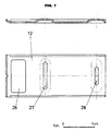
- the depth of cut of the recessing grooves to be made in the walls is adjustable via the tilting sole (12).
- This sole (12), plate 1/5 is fixed on a support (11), plate 1/5 FIG.1 and board 3/5 FIG.6 , by 3 bolts (16).
- This support (11) is articulated on an axis (13) and held in position by a bolt axis (14) moving in a circular arc-shaped light (a) of the support (10).
- the bolt shaft (14) has a head at one end and the other is threaded. On this threaded portion are positioned a washer and a nut allowing, by clamping, to maintain the depth of cut.
- the fixed support (10) board 3/5 FIG.5 and board 1/5 FIG.1 is attached to the frame of the jigsaw by 2 screws (18), depending on the type of existing attachment of the soleplate and passing through the holes (t). It comprises two ears each pierced with a hole (q) for the passage of the hinge pin (13) of the support (11) FIG.6 and two other lugs pierced by a circular arcuate lumen (a) for the passage of the bolt shaft (14).
- the depth of cut would be adjustable between 35 and 55mm. (See FIG.1 plate 1/5).
- the depth of cut can be achieved by the use of saw blades of length adapted to the desired depth of cut.
- the tool holder is composed of two independent saw blade holders (24) having at the rear a boss (22) pierced with a smooth hole for sliding on a horizontal axis (25) square or round. In the case of an axis of round section, it will have a flat on the top along its length.
- This axis (25) is integral with a U-shaped support (21) which itself is integral with the vertical axis of the jigsaw.
- the two bosses (22) have their outer surface (f) plane which slides against the inner face of the U-shaped support (21). This makes it possible to maintain them in a vertical position and prevents them from rotating.
- the two blade holders are identical to those found on most existing jigsaws and equipped with a "quick" fastening system or with locking screws (29) depending on the manufacturer. Holding in spacing position and in position vertical of the two saw blades during their use is provided by a cylindrical guide (17) board 2/5 FIG.4 coming from behind the saw blades in action. It includes circular grooves where are housed the two saw blades. The between axes of these circular grooves are predefined according to the widths of the most common grooves to be made in the walls.
Landscapes
- Engineering & Computer Science (AREA)
- Mechanical Engineering (AREA)
- Mining & Mineral Resources (AREA)
- Sawing (AREA)
- Drilling Tools (AREA)
- Processing Of Stones Or Stones Resemblance Materials (AREA)
- Electrical Discharge Machining, Electrochemical Machining, And Combined Machining (AREA)
Claims (7)
- Handbewegliche Elektrostichsäge, die aus einem, auf der zur Pendelbewegung dienenden senkrechten Achse, fixierten Sägeblatthalter besteht, der die Befestigung und die gleichzeitige Benutzung von zwei Sägeblättern ermöglicht, die sowohl in Breite als auch in Tiefe eingestellt werden können, um Rillen ausschneiden zu können, welche zum Einlegen von Elektrokabeln, kleinen Hüllen oder Röhren in aus Gips hergestellten Trennwänden, in leichten Zwischenwänden oder in mit Gips verkleideten Isoliergegenständen, die zum Temperatur- und Feuchtigkeitsschutz Wänden verkleiden,
gekennzeichnet durch :- die genannte Drehachse, welche die Pendelbewegung verursacht, besteht für den aus dem Stichsägekörper vordringenden Teil, aus einer viereckigen bzw. einer rechteckigen Form oder aus einem Profil in jeglicher Winkelform, und drängt durch eine Öffnung oder durch ein Stück Hülle, das mit einem Teilstück in Verbindung steht und zum Körper der Säge gehört, sodass während dem Rundschneiden der Rille die verursachten Drehungsbemühungen nicht weitergeleitet werden ;- wobei die genannte senkrechte Achse der Stichsäge entweder aus dem direkten Fortfahren der Achse besteht oder aus einem angelöteten Teil, oder aus der Verbindung durch Gewindeschneiden am Endteil dieser Achse.- ein Sägeblatthalter bestehend aus Teilen: ein Hinterteil (3), ein Vorderteil (4) und zwei Verbindungsschrauben (5), wobei der in Frage stehende Sägeblatthalter mit der genannten senkrechten Achse der Sticksäge durch das Hinterteil (3) solidarisch ist; die beiden Hinter- (3)und Vorderteile (4) sind jeweils mit übereinstimmenden senkrechten Rillen laut vorbestimmten Abstände (e1), (e2), et (e3) versehen(s); wobei die genannten Abstände zwischen den Rillen entsprechend der in den Wänden durchzuführenden Rillenbreiten abgestimmt werden ; die genannten senkrechten Rillen in den zwei hinteren (3) und vorderen (4) Teilen des vorliegenden Sägeblatthalters bestehen aus einer Breite, die der Dicke der genannten zwei Sägeblättern entsprechen und eine Tiefe aufweisen, die leicht unter der Hälfte der Breite der genannten Sägeblättern liegt, um einen leichten Spielsatz für das Anziehen während der Montage der vorliegenden Hinter- (3) und Vorderteilen (4) zu gewährleisten ; der Hinterteil (3) des Sägeblatthalters beträgt an beiden Extremitäten eine Randleiste (r), die das angepasste Einfügen des Vorderteils (4) vom genannten Sägeblatthalter ermöglicht ; die in Frage stehenden beiden Sägeblätter werden, nachdem sie in ihren respektiven Rillen laut gewähltem Abstand eingefügt sind, zwischen die beiden Hinter- (3) und Vorderteile (4) des Sägeblatthalters mittels zwei Schrauben (5) eingeklemmten ; da der genannte Vorderteil (4) zwischen den zwei äußersten Randleisten (r) des Hinterteils (3) gesteuert bleiben, wird der Rutsch zur Seite vermieden und somit bleiben die beiden Sägeblätter der Stichsäge in geeigneter Position. - Stichsäge laut Forderung 1 gekennzeichnet durch eine trapezförmige und waagerechte Rille (s3) oder (s4) , die auf der inneren Front und am unteren Teil der beiden Hinter- (3) und Vorderelemente (4) des vorliegenden Sägeblatthalters hergestellt wurde ; die genannte trapezförmige Rille, die das Einfügen des Formstahls, das gewisse Sägeblätter aufweisen, ermöglicht bzw. das senkrechte Aufrechthalten der in Frage stehenden Sägeblättern sichert.
- Stichsäge gemäß Forderung 2 gekennzeichnet durch ein zylindrisches Führungsteil (17), das sich hinter die zwei bewegenden Blätter ansetzt und gleichzeitig ihr Spreizen und ihre senkrechte Position bewahrt ; das vorliegende zylindrische Führungsteil (17), das über kreisförmige Rillen verfügt, in welche die genannten Sägeblätter sich einfügen ; die Breite dieser Rillen stimmen mit der Dicke der genannten Sägeblätter überein und ihre Positionen (e'1, e'2 et e'3) stimmen genau mit den Positionen der senkrechten Rillen überein (e1, e2 et e3), die in den zwei Hinter- (3) und Vorderteilen (4) des genannten Sägeblatthalters ausgeführt wurden und in welche die genannten Sägeblätter sich einfügen ; das genannte zylindrische Führungsteil (17) befindet sich in freier Drehung auf einer Achse (9) und wird von zwei Armen unterstützt (7) ; eine gespaltete Rondelle (8),die in einer kreisförmigen Rille an jedem Ende der genannten Achse eingefasst ist (9), hält das Führungselement in seiner Position zwischen den zwei Armen (17) aufrecht ; wobei die genannten zwei Arme am Körper der Stichsäge fixiert sind.
- Stichsäge laut Forderung 3 gekennzeichnet durch eine Einheit bestehend aus einer Stützsohle (12), einer beweglichen (11) und einer festen Stütze (10); da sich die Sohle (12) durch diese bewegliche Stütze (11) schräg stellen lässt, kann man die Schnitt-Tiefe der Sägeblättern in dem zu schneidenden Gegenstand und auch gemäß der Tiefe der herzustellenden Rillen entsprechend regeln ; die genannte Sohle (12) ist an die genannte bewegliche Stütze (11) durch drei Bolzen befestigt (16) ; die vorliegende bewegliche Stütze (11) ist mit vier Ösen versehen, bewegt sich auf einer Achse (13) und wird durch einen Bolzen (14) in Stellung gehalten ; die vier Ösen der genannten beweglichen Stütze bestehen aus folgenden Elemente :- zwei hintere Ösen (19), die zur Durchführung einer Achse (3)mit einem Loch versehen sind und somit Dank seines Durchganges in den Bohrungen (q) der genannten festen Stütze (10), die Bewegung der gesamten beweglichen Stütze (11) und der Stützsohle (12) ermöglichen ;- zwei vordere Ösen(20), die zum Durchgang einer Achse(14) mit einem Loch versehen sind und die in der festen Stütze (10) vorhandenen beiden bogenförmigen Schlitzen (a) durchfließen , was die Einstellung der Schnitt-Tiefe der zwei Sägeblättern ermöglicht; die Standhaltung wird durch das Anziehen der Mutter auf ihrer Achse (14) gesichert ; die genannten Ösen sind miteinander mit einem röhrförmigen Stehbolzen (e) verbunden , der ihren Abstand während dem Anziehen der Mutter auf ihrer Achse (14) bewahrt ; die feste Stütze (10) ist am Körper der Stichsäge durch zwei Schrauben (18) fixiert, wofür sie die Löcher (t) der festen Stütze benutzen.
- Stichsäge gemäß Forderung 4 gekennzeichnet durch einen Einschnitt in V Form in der Mitte und am vorderen Rand der genannten Stützsohle (12) ; der genannte Einschnitt ermöglicht, während dem Ausschneiden der Rille, die Linieführung genau zu folgen.
- Stichsäge gemäß Forderung 5 gekennzeichnet durch Schlitze (27), (28), die in der genannten Stützsohle (12) ausgeschnitten wurden, um das seitliche Einstellen der Position der vorerwähnten Stützsohle (12) auf der festen Stütze (11) zu veranlassen, wobei dieses seitliche Einstellen die Fähigkeit erteilt, die Ausschneidungen in den Trennwänden so nahe wie möglich an den Hindernissen wie zum Beispiel Tür- oder Fensterrahmen bzw. einspringende Winkel, wobei in solchem Fall der Einschnitt in V Form nicht als Wegleitung des Ausschneidens dient ; eine Ausschneidung (26) am vorderen Teil der genannten Sohle (12) ist dafür vorgesehen, sodass die zwei Sägeblätter durchdrängen können indem man gleichzeitig ihre seitliche Regelung vornimmt.
- Stichsäge gemäß Forderung 6 gekennzeichnet durch die Benützung von Sägeblättern, deren Länge der gewünschten Schnitt-Tiefe angepasst sind ; die bewegliche Stütze (11) der Stützsohle (12) ist waagerecht ohne Schrägeinstellung auf ihrer Stütz (10) befestigt.
Applications Claiming Priority (2)
| Application Number | Priority Date | Filing Date | Title |
|---|---|---|---|
| FR0403027 | 2004-03-24 | ||
| FR0403027A FR2867994B1 (fr) | 2004-03-24 | 2004-03-24 | Amenagement d'une scie sauteuse electroportative pour decoupe de saignees dans cloisons |
Publications (2)
| Publication Number | Publication Date |
|---|---|
| EP1588817A1 EP1588817A1 (de) | 2005-10-26 |
| EP1588817B1 true EP1588817B1 (de) | 2008-08-13 |
Family
ID=34941993
Family Applications (1)
| Application Number | Title | Priority Date | Filing Date |
|---|---|---|---|
| EP05290515A Not-in-force EP1588817B1 (de) | 2004-03-24 | 2005-03-08 | Anpassung einer Stichsäge zum Schneiden von Nuten in Mauern |
Country Status (4)
| Country | Link |
|---|---|
| EP (1) | EP1588817B1 (de) |
| AT (1) | ATE404340T1 (de) |
| DE (1) | DE602005008804D1 (de) |
| FR (1) | FR2867994B1 (de) |
Families Citing this family (5)
| Publication number | Priority date | Publication date | Assignee | Title |
|---|---|---|---|---|
| CN102350545B (zh) * | 2011-09-09 | 2013-12-04 | 宁波黑松工具有限公司 | 一种新型曲线锯 |
| CN102615353B (zh) * | 2012-04-12 | 2013-08-21 | 东莞市俊知自动机械有限公司 | 气动式剪贴焊片机构 |
| CN116945257A (zh) * | 2023-08-07 | 2023-10-27 | 吉安吉祥铝塑板业有限公司 | 一种手提式铝塑板开槽设备 |
| CN118238283B (zh) * | 2024-05-30 | 2024-08-06 | 江苏英派装饰材料有限公司 | 一种石膏线条辅助切割装置 |
| CN119928079B (zh) * | 2025-02-20 | 2025-08-01 | 广东高旅建设工程有限公司 | 一种墙体开槽方法及建筑施工用墙体开槽设备 |
Citations (1)
| Publication number | Priority date | Publication date | Assignee | Title |
|---|---|---|---|---|
| DE8808036U1 (de) * | 1987-06-23 | 1988-09-08 | Moskovskoe naučno-proizvodstvennoe ob"edinenie po mechanizirovannomu stroitel'nomu instrumentu i otdeločnym mašinam (NPO "VNIISMI"), Chimki, Moskovskaja oblast' | Mechanische Säge |
Family Cites Families (7)
| Publication number | Priority date | Publication date | Assignee | Title |
|---|---|---|---|---|
| CH328167A (de) * | 1955-02-19 | 1958-02-28 | Scintilla Ag | Einrichtung zum gleichzeitigen Schneiden einer Mehrfachspur |
| US4235017A (en) * | 1979-08-16 | 1980-11-25 | Harry Yavis | Saber saw attachment |
| USH571H (en) * | 1986-02-20 | 1989-02-07 | The United States Of America As Represented By The Secretary Of The Army | Double-bladed, water-cooled attachment for surgical bone cutting saw and method for using and assembling the same |
| US4719701A (en) * | 1986-10-14 | 1988-01-19 | Williams David S | Dual blade saw attachment |
| US5087261A (en) * | 1988-03-21 | 1992-02-11 | Mit Ab | Saw-blade for sawing living human bone |
| US5010652A (en) * | 1990-03-19 | 1991-04-30 | Miletich David J | Optically guided power sabre saw |
| NL9301193A (nl) * | 1993-07-07 | 1995-02-01 | Arnold Postma | Hulpstuk voor een decoupeerzaagmachine. |
-
2004
- 2004-03-24 FR FR0403027A patent/FR2867994B1/fr not_active Expired - Fee Related
-
2005
- 2005-03-08 DE DE602005008804T patent/DE602005008804D1/de not_active Expired - Lifetime
- 2005-03-08 EP EP05290515A patent/EP1588817B1/de not_active Not-in-force
- 2005-03-08 AT AT05290515T patent/ATE404340T1/de not_active IP Right Cessation
Patent Citations (1)
| Publication number | Priority date | Publication date | Assignee | Title |
|---|---|---|---|---|
| DE8808036U1 (de) * | 1987-06-23 | 1988-09-08 | Moskovskoe naučno-proizvodstvennoe ob"edinenie po mechanizirovannomu stroitel'nomu instrumentu i otdeločnym mašinam (NPO "VNIISMI"), Chimki, Moskovskaja oblast' | Mechanische Säge |
Also Published As
| Publication number | Publication date |
|---|---|
| FR2867994A1 (fr) | 2005-09-30 |
| FR2867994B1 (fr) | 2007-05-04 |
| DE602005008804D1 (de) | 2008-09-25 |
| ATE404340T1 (de) | 2008-08-15 |
| EP1588817A1 (de) | 2005-10-26 |
Similar Documents
| Publication | Publication Date | Title |
|---|---|---|
| EP3676037B1 (de) | Schneiderklemmen, schneiderklemmen-kit und schneiderklemmen- und halterahmensysteme | |
| EP3124719B1 (de) | Schalunghaltevorrichtung für bauelement, bauelement mit einer solchen vorririchtung und schalungsverfahren mit einer solchen vorrichtung | |
| EP1588817B1 (de) | Anpassung einer Stichsäge zum Schneiden von Nuten in Mauern | |
| FR2548939A1 (fr) | Butee reglable pour plateau de scie | |
| EP2300113A2 (de) | Tragbare vorrichtung zur schärfung der kanten eines skis | |
| EP0117314B1 (de) | Hobel | |
| CA2731602C (en) | Docking and miter saw | |
| KR101172407B1 (ko) | 파이프 절단 장치 | |
| FR2951099A3 (fr) | Rail de guidage pour un outillage de puissance | |
| WO2007006894A1 (fr) | Pince pour le denudage d’element tubulaire, en particulier de cable ou similaire | |
| EP2812230A1 (de) | Struktur zum aufbau einer fahrzeuglenkerposition | |
| EP0517839A1 (de) | Abnehmbare vorrichtung zum automatischen, geradlinigen führen von tragbaren säge- oder schneidmaschinen | |
| FR2914211A1 (fr) | Outil a main pour decouper une plaque. | |
| FR3026120B1 (fr) | Dispositif de pose du type papillon | |
| FR2527969A1 (fr) | Machine pour le travail du bois et ensemble porte-outil pour la construction d'une telle machine | |
| EP1732737B1 (de) | Werkzeug zum schneiden von hohlprofilen | |
| EP2398069A2 (de) | Befestigungsplatte und entsprechendes Herstellungsverfahren | |
| WO2001081054A1 (fr) | Outil anti-rebond et de retenue pour tronçonneuse et accessoires associes | |
| CH697520B1 (fr) | Procédé de fraisage de tenons et mortaises à queue d'aronde pour assembler des pièces de charpente et gabarits pour un tel procédé. | |
| BE885025A (fr) | Chaine coupante | |
| FR2793431A3 (fr) | Machine a chanfreiner | |
| FR3066934A1 (fr) | Dispositif de coupe rotatif | |
| FR2716827A1 (fr) | Tête de scie circulaire. | |
| JPH0671394B2 (ja) | 枝打機 | |
| FR2609422A1 (fr) | Boite a coupe universelle pour scie circulaire portative |
Legal Events
| Date | Code | Title | Description |
|---|---|---|---|
| PUAI | Public reference made under article 153(3) epc to a published international application that has entered the european phase |
Free format text: ORIGINAL CODE: 0009012 |
|
| AK | Designated contracting states |
Kind code of ref document: A1 Designated state(s): AT BE BG CH CY CZ DE DK EE ES FI FR GB GR HU IE IS IT LI LT LU MC NL PL PT RO SE SI SK TR |
|
| AX | Request for extension of the european patent |
Extension state: AL BA HR LV MK YU |
|
| 17P | Request for examination filed |
Effective date: 20060329 |
|
| AKX | Designation fees paid |
Designated state(s): AT BE BG CH CY CZ DE DK EE ES FI FR GB GR HU IE IS IT LI LT LU MC NL PL PT RO SE SI SK TR |
|
| GRAP | Despatch of communication of intention to grant a patent |
Free format text: ORIGINAL CODE: EPIDOSNIGR1 |
|
| GRAS | Grant fee paid |
Free format text: ORIGINAL CODE: EPIDOSNIGR3 |
|
| GRAA | (expected) grant |
Free format text: ORIGINAL CODE: 0009210 |
|
| AK | Designated contracting states |
Kind code of ref document: B1 Designated state(s): AT BE BG CH CY CZ DE DK EE ES FI FR GB GR HU IE IS IT LI LT LU MC NL PL PT RO SE SI SK TR |
|
| REG | Reference to a national code |
Ref country code: GB Ref legal event code: FG4D Free format text: NOT ENGLISH |
|
| REG | Reference to a national code |
Ref country code: CH Ref legal event code: EP |
|
| REG | Reference to a national code |
Ref country code: IE Ref legal event code: FG4D Free format text: LANGUAGE OF EP DOCUMENT: FRENCH |
|
| REF | Corresponds to: |
Ref document number: 602005008804 Country of ref document: DE Date of ref document: 20080925 Kind code of ref document: P |
|
| PG25 | Lapsed in a contracting state [announced via postgrant information from national office to epo] |
Ref country code: IS Free format text: LAPSE BECAUSE OF FAILURE TO SUBMIT A TRANSLATION OF THE DESCRIPTION OR TO PAY THE FEE WITHIN THE PRESCRIBED TIME-LIMIT Effective date: 20081213 Ref country code: LT Free format text: LAPSE BECAUSE OF FAILURE TO SUBMIT A TRANSLATION OF THE DESCRIPTION OR TO PAY THE FEE WITHIN THE PRESCRIBED TIME-LIMIT Effective date: 20080813 |
|
| PG25 | Lapsed in a contracting state [announced via postgrant information from national office to epo] |
Ref country code: SI Free format text: LAPSE BECAUSE OF FAILURE TO SUBMIT A TRANSLATION OF THE DESCRIPTION OR TO PAY THE FEE WITHIN THE PRESCRIBED TIME-LIMIT Effective date: 20080813 Ref country code: FI Free format text: LAPSE BECAUSE OF FAILURE TO SUBMIT A TRANSLATION OF THE DESCRIPTION OR TO PAY THE FEE WITHIN THE PRESCRIBED TIME-LIMIT Effective date: 20080813 Ref country code: AT Free format text: LAPSE BECAUSE OF FAILURE TO SUBMIT A TRANSLATION OF THE DESCRIPTION OR TO PAY THE FEE WITHIN THE PRESCRIBED TIME-LIMIT Effective date: 20080813 Ref country code: ES Free format text: LAPSE BECAUSE OF FAILURE TO SUBMIT A TRANSLATION OF THE DESCRIPTION OR TO PAY THE FEE WITHIN THE PRESCRIBED TIME-LIMIT Effective date: 20081124 |
|
| REG | Reference to a national code |
Ref country code: IE Ref legal event code: FD4D |
|
| PG25 | Lapsed in a contracting state [announced via postgrant information from national office to epo] |
Ref country code: BG Free format text: LAPSE BECAUSE OF FAILURE TO SUBMIT A TRANSLATION OF THE DESCRIPTION OR TO PAY THE FEE WITHIN THE PRESCRIBED TIME-LIMIT Effective date: 20081113 Ref country code: IE Free format text: LAPSE BECAUSE OF FAILURE TO SUBMIT A TRANSLATION OF THE DESCRIPTION OR TO PAY THE FEE WITHIN THE PRESCRIBED TIME-LIMIT Effective date: 20080813 Ref country code: DK Free format text: LAPSE BECAUSE OF FAILURE TO SUBMIT A TRANSLATION OF THE DESCRIPTION OR TO PAY THE FEE WITHIN THE PRESCRIBED TIME-LIMIT Effective date: 20080813 |
|
| PG25 | Lapsed in a contracting state [announced via postgrant information from national office to epo] |
Ref country code: SK Free format text: LAPSE BECAUSE OF FAILURE TO SUBMIT A TRANSLATION OF THE DESCRIPTION OR TO PAY THE FEE WITHIN THE PRESCRIBED TIME-LIMIT Effective date: 20080813 Ref country code: CZ Free format text: LAPSE BECAUSE OF FAILURE TO SUBMIT A TRANSLATION OF THE DESCRIPTION OR TO PAY THE FEE WITHIN THE PRESCRIBED TIME-LIMIT Effective date: 20080813 Ref country code: RO Free format text: LAPSE BECAUSE OF FAILURE TO SUBMIT A TRANSLATION OF THE DESCRIPTION OR TO PAY THE FEE WITHIN THE PRESCRIBED TIME-LIMIT Effective date: 20080813 Ref country code: PT Free format text: LAPSE BECAUSE OF FAILURE TO SUBMIT A TRANSLATION OF THE DESCRIPTION OR TO PAY THE FEE WITHIN THE PRESCRIBED TIME-LIMIT Effective date: 20090113 |
|
| PLBE | No opposition filed within time limit |
Free format text: ORIGINAL CODE: 0009261 |
|
| STAA | Information on the status of an ep patent application or granted ep patent |
Free format text: STATUS: NO OPPOSITION FILED WITHIN TIME LIMIT |
|
| 26N | No opposition filed |
Effective date: 20090514 |
|
| PG25 | Lapsed in a contracting state [announced via postgrant information from national office to epo] |
Ref country code: EE Free format text: LAPSE BECAUSE OF FAILURE TO SUBMIT A TRANSLATION OF THE DESCRIPTION OR TO PAY THE FEE WITHIN THE PRESCRIBED TIME-LIMIT Effective date: 20080813 |
|
| PG25 | Lapsed in a contracting state [announced via postgrant information from national office to epo] |
Ref country code: IT Free format text: LAPSE BECAUSE OF FAILURE TO SUBMIT A TRANSLATION OF THE DESCRIPTION OR TO PAY THE FEE WITHIN THE PRESCRIBED TIME-LIMIT Effective date: 20080813 |
|
| REG | Reference to a national code |
Ref country code: FR Ref legal event code: ST Effective date: 20091130 |
|
| PG25 | Lapsed in a contracting state [announced via postgrant information from national office to epo] |
Ref country code: SE Free format text: LAPSE BECAUSE OF FAILURE TO SUBMIT A TRANSLATION OF THE DESCRIPTION OR TO PAY THE FEE WITHIN THE PRESCRIBED TIME-LIMIT Effective date: 20081113 |
|
| PG25 | Lapsed in a contracting state [announced via postgrant information from national office to epo] |
Ref country code: FR Free format text: LAPSE BECAUSE OF NON-PAYMENT OF DUE FEES Effective date: 20091123 |
|
| PG25 | Lapsed in a contracting state [announced via postgrant information from national office to epo] |
Ref country code: PL Free format text: LAPSE BECAUSE OF FAILURE TO SUBMIT A TRANSLATION OF THE DESCRIPTION OR TO PAY THE FEE WITHIN THE PRESCRIBED TIME-LIMIT Effective date: 20080813 |
|
| PG25 | Lapsed in a contracting state [announced via postgrant information from national office to epo] |
Ref country code: GR Free format text: LAPSE BECAUSE OF FAILURE TO SUBMIT A TRANSLATION OF THE DESCRIPTION OR TO PAY THE FEE WITHIN THE PRESCRIBED TIME-LIMIT Effective date: 20081114 |
|
| PGFP | Annual fee paid to national office [announced via postgrant information from national office to epo] |
Ref country code: MC Payment date: 20110303 Year of fee payment: 7 |
|
| PGFP | Annual fee paid to national office [announced via postgrant information from national office to epo] |
Ref country code: LU Payment date: 20110328 Year of fee payment: 7 Ref country code: NL Payment date: 20110310 Year of fee payment: 7 Ref country code: CH Payment date: 20110304 Year of fee payment: 7 |
|
| PG25 | Lapsed in a contracting state [announced via postgrant information from national office to epo] |
Ref country code: HU Free format text: LAPSE BECAUSE OF FAILURE TO SUBMIT A TRANSLATION OF THE DESCRIPTION OR TO PAY THE FEE WITHIN THE PRESCRIBED TIME-LIMIT Effective date: 20090214 |
|
| PGFP | Annual fee paid to national office [announced via postgrant information from national office to epo] |
Ref country code: GB Payment date: 20110304 Year of fee payment: 7 Ref country code: BE Payment date: 20110304 Year of fee payment: 7 |
|
| PG25 | Lapsed in a contracting state [announced via postgrant information from national office to epo] |
Ref country code: TR Free format text: LAPSE BECAUSE OF FAILURE TO SUBMIT A TRANSLATION OF THE DESCRIPTION OR TO PAY THE FEE WITHIN THE PRESCRIBED TIME-LIMIT Effective date: 20080813 |
|
| PG25 | Lapsed in a contracting state [announced via postgrant information from national office to epo] |
Ref country code: CY Free format text: LAPSE BECAUSE OF FAILURE TO SUBMIT A TRANSLATION OF THE DESCRIPTION OR TO PAY THE FEE WITHIN THE PRESCRIBED TIME-LIMIT Effective date: 20080813 |
|
| BERE | Be: lapsed |
Owner name: OSTOJ, FRANCOIS Effective date: 20120331 |
|
| REG | Reference to a national code |
Ref country code: NL Ref legal event code: V1 Effective date: 20121001 |
|
| PG25 | Lapsed in a contracting state [announced via postgrant information from national office to epo] |
Ref country code: MC Free format text: LAPSE BECAUSE OF NON-PAYMENT OF DUE FEES Effective date: 20120331 |
|
| REG | Reference to a national code |
Ref country code: CH Ref legal event code: PL |
|
| GBPC | Gb: european patent ceased through non-payment of renewal fee |
Effective date: 20120308 |
|
| PG25 | Lapsed in a contracting state [announced via postgrant information from national office to epo] |
Ref country code: LI Free format text: LAPSE BECAUSE OF NON-PAYMENT OF DUE FEES Effective date: 20120331 Ref country code: CH Free format text: LAPSE BECAUSE OF NON-PAYMENT OF DUE FEES Effective date: 20120331 Ref country code: GB Free format text: LAPSE BECAUSE OF NON-PAYMENT OF DUE FEES Effective date: 20120308 Ref country code: BE Free format text: LAPSE BECAUSE OF NON-PAYMENT OF DUE FEES Effective date: 20120331 |
|
| PG25 | Lapsed in a contracting state [announced via postgrant information from national office to epo] |
Ref country code: NL Free format text: LAPSE BECAUSE OF NON-PAYMENT OF DUE FEES Effective date: 20121001 |
|
| PG25 | Lapsed in a contracting state [announced via postgrant information from national office to epo] |
Ref country code: LU Free format text: LAPSE BECAUSE OF NON-PAYMENT OF DUE FEES Effective date: 20120308 |
|
| PGFP | Annual fee paid to national office [announced via postgrant information from national office to epo] |
Ref country code: DE Payment date: 20140822 Year of fee payment: 10 |
|
| REG | Reference to a national code |
Ref country code: DE Ref legal event code: R081 Ref document number: 602005008804 Country of ref document: DE Owner name: SILBERKUHL-FORMING OUE, SILLAMAEE, EE Free format text: FORMER OWNER: OSTOJ, FRANCOIS, JOUY LE MOUTIER, FR Effective date: 20150313 |
|
| REG | Reference to a national code |
Ref country code: DE Ref legal event code: R119 Ref document number: 602005008804 Country of ref document: DE |
|
| PG25 | Lapsed in a contracting state [announced via postgrant information from national office to epo] |
Ref country code: DE Free format text: LAPSE BECAUSE OF NON-PAYMENT OF DUE FEES Effective date: 20151001 |