EP2398069A2 - Befestigungsplatte und entsprechendes Herstellungsverfahren - Google Patents
Befestigungsplatte und entsprechendes Herstellungsverfahren Download PDFInfo
- Publication number
- EP2398069A2 EP2398069A2 EP11169823A EP11169823A EP2398069A2 EP 2398069 A2 EP2398069 A2 EP 2398069A2 EP 11169823 A EP11169823 A EP 11169823A EP 11169823 A EP11169823 A EP 11169823A EP 2398069 A2 EP2398069 A2 EP 2398069A2
- Authority
- EP
- European Patent Office
- Prior art keywords
- slot
- plate
- head
- nut piece
- base member
- Prior art date
- Legal status (The legal status is an assumption and is not a legal conclusion. Google has not performed a legal analysis and makes no representation as to the accuracy of the status listed.)
- Withdrawn
Links
- 238000004519 manufacturing process Methods 0.000 title claims abstract description 6
- 238000000034 method Methods 0.000 claims abstract description 6
- BASFCYQUMIYNBI-UHFFFAOYSA-N platinum Chemical compound [Pt] BASFCYQUMIYNBI-UHFFFAOYSA-N 0.000 claims description 73
- 229910052697 platinum Inorganic materials 0.000 claims description 33
- 210000005069 ears Anatomy 0.000 claims description 23
- 238000005520 cutting process Methods 0.000 claims description 14
- 238000000605 extraction Methods 0.000 claims description 6
- 230000002093 peripheral effect Effects 0.000 claims description 4
- 230000000149 penetrating effect Effects 0.000 claims 1
- 230000008878 coupling Effects 0.000 description 6
- 238000010168 coupling process Methods 0.000 description 6
- 238000005859 coupling reaction Methods 0.000 description 6
- 230000015572 biosynthetic process Effects 0.000 description 3
- 208000031968 Cadaver Diseases 0.000 description 2
- 241001080024 Telles Species 0.000 description 2
- 238000009966 trimming Methods 0.000 description 2
- 230000000881 depressing effect Effects 0.000 description 1
- 238000003780 insertion Methods 0.000 description 1
- 230000037431 insertion Effects 0.000 description 1
- 238000012423 maintenance Methods 0.000 description 1
- 239000000463 material Substances 0.000 description 1
- 230000035515 penetration Effects 0.000 description 1
Images
Classifications
-
- H—ELECTRICITY
- H02—GENERATION; CONVERSION OR DISTRIBUTION OF ELECTRIC POWER
- H02S—GENERATION OF ELECTRIC POWER BY CONVERSION OF INFRARED RADIATION, VISIBLE LIGHT OR ULTRAVIOLET LIGHT, e.g. USING PHOTOVOLTAIC [PV] MODULES
- H02S20/00—Supporting structures for PV modules
- H02S20/20—Supporting structures directly fixed to an immovable object
- H02S20/22—Supporting structures directly fixed to an immovable object specially adapted for buildings
- H02S20/23—Supporting structures directly fixed to an immovable object specially adapted for buildings specially adapted for roof structures
-
- F—MECHANICAL ENGINEERING; LIGHTING; HEATING; WEAPONS; BLASTING
- F24—HEATING; RANGES; VENTILATING
- F24S—SOLAR HEAT COLLECTORS; SOLAR HEAT SYSTEMS
- F24S25/00—Arrangement of stationary mountings or supports for solar heat collector modules
- F24S25/60—Fixation means, e.g. fasteners, specially adapted for supporting solar heat collector modules
- F24S25/63—Fixation means, e.g. fasteners, specially adapted for supporting solar heat collector modules for fixing modules or their peripheral frames to supporting elements
-
- F—MECHANICAL ENGINEERING; LIGHTING; HEATING; WEAPONS; BLASTING
- F16—ENGINEERING ELEMENTS AND UNITS; GENERAL MEASURES FOR PRODUCING AND MAINTAINING EFFECTIVE FUNCTIONING OF MACHINES OR INSTALLATIONS; THERMAL INSULATION IN GENERAL
- F16B—DEVICES FOR FASTENING OR SECURING CONSTRUCTIONAL ELEMENTS OR MACHINE PARTS TOGETHER, e.g. NAILS, BOLTS, CIRCLIPS, CLAMPS, CLIPS OR WEDGES; JOINTS OR JOINTING
- F16B37/00—Nuts or like thread-engaging members
- F16B37/04—Devices for fastening nuts to surfaces, e.g. sheets, plates
- F16B37/06—Devices for fastening nuts to surfaces, e.g. sheets, plates by means of welding or riveting
- F16B37/062—Devices for fastening nuts to surfaces, e.g. sheets, plates by means of welding or riveting by means of riveting
- F16B37/065—Devices for fastening nuts to surfaces, e.g. sheets, plates by means of welding or riveting by means of riveting by deforming the material of the nut
-
- F—MECHANICAL ENGINEERING; LIGHTING; HEATING; WEAPONS; BLASTING
- F24—HEATING; RANGES; VENTILATING
- F24S—SOLAR HEAT COLLECTORS; SOLAR HEAT SYSTEMS
- F24S25/00—Arrangement of stationary mountings or supports for solar heat collector modules
- F24S25/60—Fixation means, e.g. fasteners, specially adapted for supporting solar heat collector modules
- F24S2025/6006—Fixation means, e.g. fasteners, specially adapted for supporting solar heat collector modules by using threaded elements, e.g. stud bolts
-
- Y—GENERAL TAGGING OF NEW TECHNOLOGICAL DEVELOPMENTS; GENERAL TAGGING OF CROSS-SECTIONAL TECHNOLOGIES SPANNING OVER SEVERAL SECTIONS OF THE IPC; TECHNICAL SUBJECTS COVERED BY FORMER USPC CROSS-REFERENCE ART COLLECTIONS [XRACs] AND DIGESTS
- Y02—TECHNOLOGIES OR APPLICATIONS FOR MITIGATION OR ADAPTATION AGAINST CLIMATE CHANGE
- Y02B—CLIMATE CHANGE MITIGATION TECHNOLOGIES RELATED TO BUILDINGS, e.g. HOUSING, HOUSE APPLIANCES OR RELATED END-USER APPLICATIONS
- Y02B10/00—Integration of renewable energy sources in buildings
- Y02B10/10—Photovoltaic [PV]
-
- Y—GENERAL TAGGING OF NEW TECHNOLOGICAL DEVELOPMENTS; GENERAL TAGGING OF CROSS-SECTIONAL TECHNOLOGIES SPANNING OVER SEVERAL SECTIONS OF THE IPC; TECHNICAL SUBJECTS COVERED BY FORMER USPC CROSS-REFERENCE ART COLLECTIONS [XRACs] AND DIGESTS
- Y02—TECHNOLOGIES OR APPLICATIONS FOR MITIGATION OR ADAPTATION AGAINST CLIMATE CHANGE
- Y02E—REDUCTION OF GREENHOUSE GAS [GHG] EMISSIONS, RELATED TO ENERGY GENERATION, TRANSMISSION OR DISTRIBUTION
- Y02E10/00—Energy generation through renewable energy sources
- Y02E10/40—Solar thermal energy, e.g. solar towers
- Y02E10/47—Mountings or tracking
-
- Y—GENERAL TAGGING OF NEW TECHNOLOGICAL DEVELOPMENTS; GENERAL TAGGING OF CROSS-SECTIONAL TECHNOLOGIES SPANNING OVER SEVERAL SECTIONS OF THE IPC; TECHNICAL SUBJECTS COVERED BY FORMER USPC CROSS-REFERENCE ART COLLECTIONS [XRACs] AND DIGESTS
- Y02—TECHNOLOGIES OR APPLICATIONS FOR MITIGATION OR ADAPTATION AGAINST CLIMATE CHANGE
- Y02E—REDUCTION OF GREENHOUSE GAS [GHG] EMISSIONS, RELATED TO ENERGY GENERATION, TRANSMISSION OR DISTRIBUTION
- Y02E10/00—Energy generation through renewable energy sources
- Y02E10/50—Photovoltaic [PV] energy
Definitions
- the present invention generally relates to mounting plates preferably for fixing photovoltaic panels on the roof of a building.
- the invention relates more particularly to a mounting plate intended to be fixed on a support structure, such as a tray formed of a corrugated plate, said plate comprising a plate-like body having at least one slot.
- the mounting of photovoltaic panels on a roof is generally done by fixing a support structure formed of corrugated plates called bins, fixed by screws and / or jumpers on the roof panes. Then we just fix plates on said bins.
- Each plate comprises screw / nut type coupling means for receiving a fastener threaded on the screw to wedge and support a panel on said bins.
- the plates are positioned to allow the maintenance of the panel at each of its opposite edges called vertical corresponding to the edges of the panels parallel to the trusses of the roof.
- the coupling means of the fastener to the plate are complex since they comprise a set formed of a screw to pass through the slot from below the plate to position the screw head on the lower side of the plate, a lock nut to be threaded onto the threaded rod of the screw on the upper side of the plate, and a nut to be threaded onto the rod after the attachment piece so as to sandwich a part of the fastener between the nut and the lock nut.
- Such a design of the platinum coupling means known from the state of the technique requires a large number of parts and complex handling for the operator.
- the nut system can be lost during disassembly of said system relative to the platen.
- the solution of the document W02007 / 044197 has the disadvantage of having to complicate the design of the nut part since the design of a nut part according to the document W02007 / 044197 requires a clearance in the room from the design of the room.
- the object of the present invention is to provide a mounting plate for which the coupling means to the plate of the fastener comprise a reduced number of parts, and without risk of loss of at least a portion of said coupling means.
- Another object of the present invention is to provide a mounting plate through which the coupling of the fastener to the plate is easily performed with a reduced number of manipulations.
- the subject of the invention is a fixing plate intended to be fixed on a support structure, such as a tray formed of a corrugated plate, said platen comprising a plate-like body having at least one slot, said platen body being provided with at least one nut piece formed by a base member extending from one side of the platen body and through which is provided a screw hole located opposite the slot, said base member having an overall width, taken orthogonally to the longitudinal axis of the slot, greater than the width of said slot, said nut piece also comprising at least one head member extending from the base member to through the slot, said at least one head member having at least two parts, referred to as lugs, which extend, with respect to the opening of the slot, on the side of the platinum body opposite the base member and on the side and other of the longitudinal axis of the corresponding slot, at the longitudinal edges of said slot, said base member and said or each head member being formed in one piece, characterized in that said base member and the ears of said or each head member form abut
- the shape of the slot and that of the nut piece prevent said nut piece from being extracted from the slot, in one direction or the other, regardless of the position of the nut piece along the slot.
- the slot is devoid of zone allowing extraction of said nut piece contrary to the solution of the document WO 2007/044197 .
- each longitudinal edge of the slot is sandwiched between the base member and an ear of the head member to hold the nut piece trapped in the platen. while allowing its sliding along the slot.
- each ear forms in cooperation with the base member anti-extraction stops of said nut piece.
- the longitudinal edges of the slot form sliding guide rails of the corresponding nut piece.
- the plate can thus be delivered with the nut part, without the operator needs to mount said nut piece in the plate.
- the fact of imprisoning the nut piece prevents it from being lost.
- the nut piece can slide freely along the slot in which it is trapped to adapt the position of the nut piece, and thus the position of the fastener, to the position of the edge of the panel that comes over platinum.
- each plate makes it possible to span the intermediate zone between two waves of a tank and thus to position at the level of said intermediate zone the fastening piece by sliding along the slot of the nut piece which receives the fastening piece. to hold a panel end edge that would be located at the right of the middle zone.
- the nut part of the plate according to the invention while being made in one piece, is rendered captive of the slot without the possibility of escaping said slot, thanks to the deformation of the head element once introduced the piece nut in the slot, which does not require a particular complex design of the nut piece before its introduction into slot.
- the overall width of said nut piece of the plate according to the invention remains greater than the width of the slot at any point of the slot. .
- the plate according to the invention thus makes it possible to benefit from a nut piece trapped in the slot through which it extends while maintaining a conventional slot shape, preferably oblong.
- the nut-piece can be introduced, before forming the ears, easily in the slot which can be carried out simply without requiring an enlarged opening, since the nut-piece is made prisoner of the slot simply by deformation of the head portion after introduction of the nut piece through the slot of the platinum body.
- each head member of the nut piece which extends between the corresponding lugs and the base member is of width slightly less than the width of the slot along which can slide said nut piece to allow the piece nut to slide along the slot, in the free state of said nut piece relative to the fastener and the panel to be fixed on the plate, while limiting the lateral play of the nut piece relative to the slot.
- the overall width of the head member and that of the base member are each greater than the overall width of the slot and thus form stops located on either side the opening plan of the slot.
- the piece has no pivotal freedom around the axis of its orifice.
- said nut piece is slidable along the slot but retains substantially the same angular orientation with respect to said slot.
- said nut piece comprises two head elements distributed on either side of the screw passage axis formed through the nut piece, each head element having two ears and the straight line by the two head members being substantially parallel to the longitudinal axis of the corresponding slot.
- the design of two head elements distributed on either side of the screw-threading axis of the nut piece makes it possible to center and position the screw passage opposite the corresponding slot of the plate during the assembly of the elements of the head through the slot.
- the two head members spaced along the slot provide a reliable sliding guide of the nut piece along the slot.
- said plate comprises two slots each enclosing a nut piece, said slots being oriented parallel to each other being spaced apart from each other in their direction longitudinal, and, secondly, spaced apart from each other in a direction transverse to their longitudinal direction.
- the plates with two slots are so-called platinum plates three waves, that is to say of length chosen to ride three waves of a tray.
- the two slots make it possible to benefit from a race for fixing a panel over a great length of the plate by combining the two slots, while benefiting from a good tearing resistance of each slot that extends only on a part of the length of the plate.
- the two slots allow to avoid the problems of overlapping of the panels with respect to their fixing zones by using the fastening part of a slot or another depending on the width of the panel and by shifting said fastener along the slot chosen according to the position of the edge of the panel above the plate.
- each slot is made by cutting the platinum body and depressing the peripheral edge of the slot towards the side of the platinum body at which the base element is intended to be positioned, so that the or each head member of the nut piece which extends through the slot, does not protrude from the flush plane of the face of the platinum body located opposite the side of the base member.
- said or each head element is obtained by partial cutting and deformation of a part of the base element.
- the or each part intended to form the head element is partially cut out and brought to project from one side of said base element.
- each lug is made by incising a portion of the corresponding head element and spacing said portion transversely to the longitudinal axis of the slot.
- the nut piece is applied to the plate so as to bring the upper face of the base member against the lower face of the plate in an orientation in which the or each head element passes through the corresponding slot of the plate, the screw hole is located opposite the slot.
- the platen / nut piece assembly is then stuck on a support and two incisions are made in the or each head element using a press and a puncture tool adapted to separate from each other the ears of the or each head element, to bring said lugs facing the longitudinal edges of the slot to trap the nut piece in the slot by sandwiching said longitudinal edges of the slot between the ears and the base member.
- the lugs are made using a two-point puncture tool and the head elements are formed by a two-blade puncture tool.
- the longitudinal edges of the plate each have a folded portion in return so as to increase the rigidity of the plate.
- the end portions of the plate are folded so as to have at least one part extending to the corresponding free end edge at a given angle with respect to the mean plane of the body.
- platinum, said inclined portions of the opposite ends of the plate being oriented inverted V in the fixed position of the plate on said support structure.
- the width of the slot at this position of the piece-nut it is that is, the distance between the longitudinal edges of the slot at this position along the longitudinal axis of the slot is less than the overall width of the head member taken at the outside of the slots. ears, so that the nut piece is definitely trapped in the corresponding slot.
- the ears are formed by the opposite side portions of the or each head member which are deformed to bring them into line with the slot edges so that each slot edge is trapped between the base member and an ear of the head element.
- the deformation of said base element for obtaining said or each head element is achieved by puncturing with the aid of a tool with two blades separated from each other by a distance corresponding to the desired width of the head element.
- each tip intended for the formation of an ear, has a straight cutting portion and an inclined cutting portion allowing, during the penetration of the tip in the head member, to move said ear to be made towards the outside of the head element.
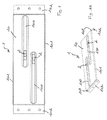
- the invention relates to a mounting plate 1 to be fixed on a support structure, such as a tray formed of a corrugated plate.
- Said plate 1 comprises a plate-like body 10 having at least one slot 100 formed along the longitudinal axis of the plate.
- said platinum body 1 is equipped with at least one nut piece 2 formed by a base member 21 extending on the side of the so-called lower face of the platinum body 1 and through which is provided a threaded hole 200 threaded located opposite the slot 100.
- the nut piece 2 is intended to receive a screw on which is to be threaded a fastener for holding an object, preferably a panel, such as a photovoltaic panel.
- the lower face of the plate is that intended to be oriented on the side of the support structure and the upper face is that intended to be oriented panel side.
- Said base element 21 has an overall width, taken orthogonally to the longitudinal axis of the slot 100, greater than the width of said slot, to prevent extraction of the base element 21 through the slot 100.
- said base element 21 is dimensioned so as to have at least one part extending, on one side of the platinum body, on either side of the longitudinal axis of the slot 100 to form an abutment. -extraction relative to the slot.
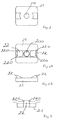
- Said nut piece 2 also comprising at least one head member 22 extending from the base member 21 through the slot 100.
- said nut piece 2 comprises two head members 22 distributed on either side of the axis of passage 200 of screw formed through the nut piece 2.
- Each head member 22 has two ears. 220 and the straight line passing through the two head members 22 are substantially parallel to the longitudinal axis of the corresponding slot 100.
- Each head member 22 has at least two parts, called lugs 220, which extend, with respect to the opening of the slot 100, on the side of the platinum body opposite the base member 21, on both sides. other of the longitudinal axis of the slot 100 so as to maintain the nut piece 2 captive of the slot 100.
- the two ears extend on either side of the slot relative to the plane orthogonal to the plane opening of the slot and passing through the longitudinal axis of the slot, in line with a longitudinal edge.
- Each lug 220 extends above and opposite a longitudinal edge of the slot to sandwich said longitudinal edge with the base member 21.
- Said base element 21 and each head element 22 are formed in one piece.
- the ears of the nut piece extend on the upper side of the plate and the base member is located on the lower side.
- the ears of the nut part extend lower side of the plate and that the base member is located on the upper side.
- the turntables are decks of length chosen to be mounted astride at least two waves.
- the support structure comprises platinums, called three-wave platters, the length of which is chosen so as to allow their mounting astride three waves.
- Said platen 1 comprises two slots 100 each enclosing a nut piece 2.
- Said slots 100 are oriented parallel to each other being spaced apart from each other in their longitudinal direction, and, secondly, spaced apart one of the other in a direction transverse to their longitudinal direction.
- Such a two-slot platen design makes it possible to improve the rigidity of each slot and thus to limit the risk of tearing of the nut through the slot while offering a wide range of possible positions of the fastener intended for be coupled to the nut piece for fixing a panel.
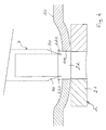
- Each slot 100 is made by cutting the platinum body flat, then driving the peripheral edge of the slot 100 towards the lower side of the platen body, so that the or each head member 22 of the nut part 2 which extends through the slot 100, does not protrude from the flush plane of the upper face of the platinum body.
- said peripheral edge of the slot protrudes from the lower face of the body of the plate, while maintaining a so-called flat slot edge, that is to say a slot border extending in a plane substantially parallel to the average plane of the body of the plate.
- the or each slot is made using a press provided with a punch of oblong section which is brought against the plate with an angle, preferably reduced, not to tear the material of the plate. Then another tool, called dithering, is brought against the edge of the slot to drive it slightly so as to perform a squelching operation of the slot.
- the trimming allows to increase the rigidity of the slot and thus limit the risk of tearing the nut piece through the slot. In addition, the trimming allows to lower the slot relative to the upper face of the plate so that the head members of the nut piece do not exceed the upper face of the plate.
- Each head member 22 is obtained by partially cutting and deforming a portion of the base member 21 such that each portion for forming the head member 22 projects from one side of said base member. 21 to be introduced through the slot.
- the deformation of the base element to form the head elements is obtained using a tool, called puncture, with two blades having two blades spaced apart by a distance corresponding to the desired head width before completion of ears of said head, that is to say a distance less than the width of the slot to allow the passage of each head element through the corresponding slot.
- punching means an incomplete cutting operation using a punch or shears, the knockout obtained being not completely detached from the workpiece.
- Each lug 220 is made by incising a top portion of the corresponding head member 22 and spacing said portion orthogonal to the longitudinal axis of the slot. In particular, each lug 220 is delimited between a free lateral edge of the corresponding head element 22 and the incision area made by the two-blade puncture tool.
- Each incision is preferably made using a tool 7 with two teeth or tips 70.
- Each tooth or tip 70 has a portion or straight cutting edge, with respect to the axis in which is intended to be moved. tool relative to the nut piece to form each lug, and an inclined cutting portion or cutting edge, with respect to said straight cutting portion or cutting edge, so as to move the incised portion of the head member towards, and especially in line with, a longitudinal edge of the slot.
- the longitudinal edges of the plate each have a folded portion back 101 on the lower face of the platen body so as to increase the rigidity of the plate.
- the end portions of the plate 1 are bent to have a portion 102 extending to the corresponding free end edge at a given angle with respect to the middle plane of the platinum body. Said inclined portions 102 of the opposite ends of the plate 1 are oriented in inverted V in the fixed position of the plate on said support structure.
- Said inclined parts allow mounting of the saddle board on several waves, preferably two or three, a tray.
- Said parties inclined each abut against a side of a wave, to be fixed by screwing on the outer flanks of the set of waves that the plate overlaps.
- each end portion of the plate has through holes.
- the end portions also each include a so-called straight portion, in return, substantially perpendicular to the middle plane of the platinum main body, which extends between the end inclined portion and the platinum main body.
- the fixing plate according to the invention with a captive nut can be produced according to the following method, using a plate-like body 10 having at least one slot 100 and a piece nut 2 formed by a base member 21 having two opposite faces through which is provided a hole 200 for screw passage.
Landscapes
- Engineering & Computer Science (AREA)
- Chemical & Material Sciences (AREA)
- Mechanical Engineering (AREA)
- Sustainable Development (AREA)
- Sustainable Energy (AREA)
- Thermal Sciences (AREA)
- Physics & Mathematics (AREA)
- Combustion & Propulsion (AREA)
- Life Sciences & Earth Sciences (AREA)
- General Engineering & Computer Science (AREA)
- Architecture (AREA)
- Civil Engineering (AREA)
- Structural Engineering (AREA)
- Connection Of Plates (AREA)
- Handling Of Sheets (AREA)
Applications Claiming Priority (1)
| Application Number | Priority Date | Filing Date | Title |
|---|---|---|---|
| FR1002520A FR2961276B1 (fr) | 2010-06-15 | 2010-06-15 | Platine de fixation et procede de fabrication correspondant. |
Publications (2)
| Publication Number | Publication Date |
|---|---|
| EP2398069A2 true EP2398069A2 (de) | 2011-12-21 |
| EP2398069A3 EP2398069A3 (de) | 2012-02-22 |
Family
ID=43530960
Family Applications (1)
| Application Number | Title | Priority Date | Filing Date |
|---|---|---|---|
| EP11169823A Withdrawn EP2398069A3 (de) | 2010-06-15 | 2011-06-14 | Befestigungsplatte und entsprechendes Herstellungsverfahren |
Country Status (2)
| Country | Link |
|---|---|
| EP (1) | EP2398069A3 (de) |
| FR (1) | FR2961276B1 (de) |
Families Citing this family (2)
| Publication number | Priority date | Publication date | Assignee | Title |
|---|---|---|---|---|
| US10505492B2 (en) | 2016-02-12 | 2019-12-10 | Solarcity Corporation | Building integrated photovoltaic roofing assemblies and associated systems and methods |
| CN112535470B (zh) * | 2020-12-11 | 2023-09-22 | 江西影创信息产业有限公司 | 一种杠杆式对插固定结构 |
Citations (1)
| Publication number | Priority date | Publication date | Assignee | Title |
|---|---|---|---|---|
| WO2007044197A2 (en) | 2005-10-06 | 2007-04-19 | Bp Corporation North America Inc. | System for mounting a solar module on a roof or the like and method of installing |
Family Cites Families (2)
| Publication number | Priority date | Publication date | Assignee | Title |
|---|---|---|---|---|
| JP4190339B2 (ja) * | 2003-04-23 | 2008-12-03 | 三洋電機株式会社 | 屋根に固定される太陽電池装置 |
| DE202008016000U1 (de) * | 2008-11-28 | 2009-03-05 | Haticon Ag | Geteilt ausgebildeter Dachhaken |
-
2010
- 2010-06-15 FR FR1002520A patent/FR2961276B1/fr active Active
-
2011
- 2011-06-14 EP EP11169823A patent/EP2398069A3/de not_active Withdrawn
Patent Citations (1)
| Publication number | Priority date | Publication date | Assignee | Title |
|---|---|---|---|---|
| WO2007044197A2 (en) | 2005-10-06 | 2007-04-19 | Bp Corporation North America Inc. | System for mounting a solar module on a roof or the like and method of installing |
Also Published As
| Publication number | Publication date |
|---|---|
| FR2961276B1 (fr) | 2012-06-29 |
| EP2398069A3 (de) | 2012-02-22 |
| FR2961276A1 (fr) | 2011-12-16 |
Similar Documents
| Publication | Publication Date | Title |
|---|---|---|
| EP3157837B1 (de) | Bandklemme mit durchgangsreifen und spannwerkzeug | |
| EP2481937B1 (de) | Verbindungsvorrichtung zum Zusammenbau von zwei Profilen | |
| EP3907411A1 (de) | Stift | |
| EP1963688B1 (de) | Anordnung zur zusammensetzung zweier teile durch schraubbefestigung über ein schrauben-muttern-system | |
| EP2398069A2 (de) | Befestigungsplatte und entsprechendes Herstellungsverfahren | |
| EP1945881A1 (de) | Verfahren zur befestigung von blättern an einer stützstruktur und verbessertes befestigungselement | |
| EP1684953B1 (de) | Vorrichtung zum schneiden von durchführungen in einen block aus isoliermaterial | |
| EP0869862B1 (de) | Verstellbare zange | |
| EP2657429B1 (de) | Befestigungssystem für Holzleisten zur Erstellung einer Terrasse | |
| WO2009018914A1 (fr) | Dispositif de fixation comportant au moins un boulon et un ecrou cooperants | |
| FR3004067A1 (fr) | Profile, notamment metallique, destine a permettre une fixation d'un film sur une structure de serre et systeme de fixation d'un film sur une structure de serre comprenant un tel profile | |
| EP3162980A1 (de) | Verstrebungsvorrichtung für die verkleidung einer struktur | |
| FR3044723A1 (fr) | Ensemble de montage a rainures inclinees | |
| EP1741938A1 (de) | Käfiganordnung für eine Käfigmutter | |
| FR2969744A1 (fr) | Element et methode de fixation d'au moins un panneau photovoltaique sur un rail et installation comprenant au moins un tel element | |
| EP1611786B1 (de) | Angelzubehör, insbesondere Drahtschneider | |
| WO2011003522A1 (fr) | Dispositif de fixation a elements de fixation multiples dont l'un est flottant | |
| EP3816458A1 (de) | Klammer zum halten von zwei flachen elementen | |
| EP3442852B1 (de) | Anordnung einer abschirmung und eines karosserieelements eines kraftfahrzeugs, insbesondere eines karosserieelements aus blech | |
| EP3093111B1 (de) | Schneidewerkzeug mit abnehmbarer klinge, und klinge für dieses werkzeug | |
| FR2998624A1 (fr) | Systeme d'assemblage de troncons de chemins de cables en tole perforee | |
| FR2677084A1 (fr) | Dispositif d'assemblage pour profiles creux. | |
| FR2953801A1 (fr) | Gabarit pour faciliter la mise en place de baguettes sur les portes d'un vehicule automobile | |
| FR2715699A1 (fr) | Organe d'assemblage pour deux pièces en bois munies d'une rainure. | |
| EP2000271B1 (de) | Herstellungsverfahren eines Holzlamellenpaneels und so erhaltenes Paneel |
Legal Events
| Date | Code | Title | Description |
|---|---|---|---|
| AK | Designated contracting states |
Kind code of ref document: A2 Designated state(s): AL AT BE BG CH CY CZ DE DK EE ES FI FR GB GR HR HU IE IS IT LI LT LU LV MC MK MT NL NO PL PT RO RS SE SI SK SM TR |
|
| AX | Request for extension of the european patent |
Extension state: BA ME |
|
| PUAI | Public reference made under article 153(3) epc to a published international application that has entered the european phase |
Free format text: ORIGINAL CODE: 0009012 |
|
| PUAL | Search report despatched |
Free format text: ORIGINAL CODE: 0009013 |
|
| AK | Designated contracting states |
Kind code of ref document: A3 Designated state(s): AL AT BE BG CH CY CZ DE DK EE ES FI FR GB GR HR HU IE IS IT LI LT LU LV MC MK MT NL NO PL PT RO RS SE SI SK SM TR |
|
| AX | Request for extension of the european patent |
Extension state: BA ME |
|
| RIC1 | Information provided on ipc code assigned before grant |
Ipc: F24J 2/52 20060101ALI20120119BHEP Ipc: H01L 31/048 20060101AFI20120119BHEP |
|
| 17P | Request for examination filed |
Effective date: 20120710 |
|
| STAA | Information on the status of an ep patent application or granted ep patent |
Free format text: STATUS: THE APPLICATION IS DEEMED TO BE WITHDRAWN |
|
| 18D | Application deemed to be withdrawn |
Effective date: 20150106 |