EP3674485A1 - Nutzfahrzeug - Google Patents
Nutzfahrzeug Download PDFInfo
- Publication number
- EP3674485A1 EP3674485A1 EP18855228.5A EP18855228A EP3674485A1 EP 3674485 A1 EP3674485 A1 EP 3674485A1 EP 18855228 A EP18855228 A EP 18855228A EP 3674485 A1 EP3674485 A1 EP 3674485A1
- Authority
- EP
- European Patent Office
- Prior art keywords
- posture
- engine hood
- box body
- cam
- manipulation
- Prior art date
- Legal status (The legal status is an assumption and is not a legal conclusion. Google has not performed a legal analysis and makes no representation as to the accuracy of the status listed.)
- Granted
Links
Images


Classifications
-
- E—FIXED CONSTRUCTIONS
- E02—HYDRAULIC ENGINEERING; FOUNDATIONS; SOIL SHIFTING
- E02F—DREDGING; SOIL-SHIFTING
- E02F9/00—Component parts of dredgers or soil-shifting machines, not restricted to one of the kinds covered by groups E02F3/00 - E02F7/00
- E02F9/16—Cabins, platforms, or the like, for drivers
- E02F9/166—Cabins, platforms, or the like, for drivers movable, tiltable or pivoting, e.g. movable seats, dampening arrangements of cabins
-
- E—FIXED CONSTRUCTIONS
- E02—HYDRAULIC ENGINEERING; FOUNDATIONS; SOIL SHIFTING
- E02F—DREDGING; SOIL-SHIFTING
- E02F9/00—Component parts of dredgers or soil-shifting machines, not restricted to one of the kinds covered by groups E02F3/00 - E02F7/00
- E02F9/08—Superstructures; Supports for superstructures
- E02F9/0858—Arrangement of component parts installed on superstructures not otherwise provided for, e.g. electric components, fenders, air-conditioning units
-
- E—FIXED CONSTRUCTIONS
- E02—HYDRAULIC ENGINEERING; FOUNDATIONS; SOIL SHIFTING
- E02F—DREDGING; SOIL-SHIFTING
- E02F9/00—Component parts of dredgers or soil-shifting machines, not restricted to one of the kinds covered by groups E02F3/00 - E02F7/00
- E02F9/20—Drives; Control devices
-
- E—FIXED CONSTRUCTIONS
- E02—HYDRAULIC ENGINEERING; FOUNDATIONS; SOIL SHIFTING
- E02F—DREDGING; SOIL-SHIFTING
- E02F9/00—Component parts of dredgers or soil-shifting machines, not restricted to one of the kinds covered by groups E02F3/00 - E02F7/00
- E02F9/20—Drives; Control devices
- E02F9/2004—Control mechanisms, e.g. control levers
Definitions
- the present invention relates to a work vehicle including a console box.
- Patent Document 1 discloses this type of work vehicle.
- PTL 1 discloses a revolving work vehicle including a driving manipulation unit.
- the driving manipulation unit includes a lever stand that is disposed laterally to a driver's seat, that is provided with a manipulation lever including a work lever and a lock lever, and that is turnable in conjunction with the manipulation lever.
- the work lever is coupled to a substantially y-shaped coupling arm at a location inside the lever stand.
- the lock lever is supported by the coupling arm such that the lock lever is turnable in a top-bottom direction.
- a driver's seat support frame is provided with a guide plate, which has a guide hole having a substantially inverted S-shape. Into the guide hole, a guide pin protruding from a cam is inserted in a slidable manner.
- the cam is configured to turn integrally with the lock lever.
- a spring configured to exert biasing force in a pulling direction is disposed. The spring biases the lock lever so that the lock lever turns forward and downward.
- a biasing member such as a gas damper, is interposed between the coupling arm and the driver's seat support frame. The biasing member biases the coupling arm in a direction in which the coupling arm turns downward.
- Patent Literature 2 (hereinafter, referred to as PTL 2) discloses a work vehicle including a lock lever that is configured to enable or disable manipulation of a manipulation lever and that is biased by a helical torsion spring.
- PTL 2 discloses, as a construction machine vehicle, a bulldozer including a driver's seat and a dashboard between which a boarding passageway region resides.
- a bulldozer including a driver's seat and a dashboard between which a boarding passageway region resides.
- lock levers are respectively provided on both sides of the driver's seat.
- the lock levers are configured to be turnable to lock or unlock a manipulation system of the bulldozer.
- the lock lever has a proximal end fixed to a lever shaft.
- the lever shaft has an intermediate portion rotatably supported by a bearing that is fixed to a frame member provided in a vehicle body. It should be noted that the frame member is not configured to turn.
- the lever shaft has a distal end fixed to an output lever, which has a distal end provided with a cam pin.
- the frame member supports a cam plate such that the cam plate is turnable.
- the cam plate has a cam groove engageable with the cam pin.
- the cam plate is coupled, via a rod, to a switching lever for a circuit on/off valve disposed in a pilot circuit of the manipulation system.
- a toggle spring which is made of a helical torsion spring, is interposed between the output lever of the lock lever and the frame member.
- the toggle spring biases the lock lever for positioning the lock lever at position A or position B.
- the lock lever is biased by the spring that is configured to exert biasing force in the pulling direction.
- the spring that is configured to exert biasing force in the pulling direction.
- a large space is required inside the lever stand, in consideration of deformation of the spring. This often leads to upsizing of the lever stand, and thus application thereof becomes difficult, especially to a small revolving work vehicle, for example.
- the helical torsion spring is disposed in such a manner that the helical torsion spring connects the output lever of the lock lever and the frame member. Therefore, it is difficult to make the configuration including the frame member, the cam plate, the output lever, and the helical torsion spring compact. In this point, improvements have been required for the configuration of PTL 2.
- the present invention was made in view of the above circumstances, and has an object to provide a console box having a compact configuration for biasing a lock lever.
- the console box includes a box body, a manipulation lever, a lock lever, a biasing member, and a lock cam.
- the box body is turnable between a first posture and a second posture, the second posture being achieved as a result of upward movement of the box body from the first posture.
- the manipulation lever is arranged to protrude from the box body.
- the lock lever is arranged to protrude from the box body, and is configured to be turnable.
- the biasing member is configured to bias the box body in a direction for bringing the box body into the second posture.
- the lock cam is configured to lock turning of the box body both in the first posture and in the second posture.
- the lock cam includes a guide member and a cam arm.
- the guide member has a cam groove.
- the cam arm is configured to turn integrally with the lock lever.
- the cam arm has an insertion portion inserted into the cam groove.
- a helical torsion spring is arranged to connect the cam arm and the guide member, the helical torsion spring being configured to bias the cam arm.
- the cam arm inverts a direction in which the box body is caused to turn by a biasing force of the helical torsion spring.
- the helical torsion spring has a coil portion arranged closer to a center in a left-right direction of the box body than is the guide member.
- the configuration adopting the helical torsion spring that has a minimum spring size and that is capable of providing a large stroke, the space inside the box body can be effectively used. Consequently, it is possible to easily make the console box compact.
- the cam arm includes an arm body having a plate shape and an inwardly protruding portion.
- the arm body is arranged closer to the center in the left-right direction of the box body than is the guide member.
- the inwardly protruding portion protrudes from the arm body toward the center in the left-right direction of the box body.
- the helical torsion spring has a spring wire having a first end attached to the guide member and a second end attached to the inwardly protruding portion.
- the cam arm can be biased by the helical torsion spring, which can contribute greatly to space saving.
- the work vehicle described above is preferably configured such that, both in a case where the box body is in the first posture and in a case where the box body is in the second posture, the coil portion of the helical torsion spring is above a portion of the guide member to which portion the spring wire is attached.
- the spring wire extends downward so as to be connected to the guide member. Consequently, the coil portion of the helical torsion spring hardly interferes with other components inside the box body. As a result, it is possible to achieve a compact structure.
- a work vehicle includes manipulation levers, a steering box, and a traveling speed stage changing device.
- the manipulation levers are respectively disposed on the left and right sides of a driver's seat.
- the steering box is arranged to protrude upward from a floor that is in front of the driver's seat.
- the traveling speed stage changing device is manipulated by an operator to change a traveling speed stage from one to another.
- the traveling speed stage changing device is disposed in an upper portion of the steering box.
- the traveling speed stage changing device is disposed at a position that can be viewed by the operator sitting on the driver's seat. This allows the operator to easily check which of a high speed stage and a low speed stage has been selected by manipulation.
- the traveling speed stage changing device is disposed in the steering box, which is located in front of the driver's seat. This allows the operator to perform manipulation for changing the traveling speed stage from one to another either with left hand or right hand, thereby making it possible to enhance the freedom in manipulation.
- the work vehicle described above preferably includes a display device arranged on the steering box, the display device being configured to display a manipulated state of the traveling speed stage changing device.
- the work vehicle described above preferably includes the following features. Namely, the work vehicle includes a traveling lever disposed in the steering box.
- the traveling speed stage changing device is arranged at a location shifted from the traveling lever viewed in a left-right direction of the steering box.
- the operator can manipulate the traveling lever with one hand and the traveling speed stage changing device with the other hand at the same time. This can enhance convenience for manipulation with both hands.
- the work vehicle described above preferably includes the following features. Namely, the work vehicle includes a first port, a second port, and a foot pedal, each of which is provided to drive an attachment work machine.
- the foot pedal is used by the operator to manipulate the attachment work machine with his/her foot.
- When the foot pedal is manipulated to be displaced from a neutral position toward a first side, operating oil is fed to the first port. Meanwhile, when the foot pedal is manipulated to be displaced toward a second side that is opposed to the first side, operating oil is fed to the second port.
- the operator can manipulate the double-acting cylinder by stepping on the single foot pedal toward the first side/the second side. This can provide the operator with intuitive and user-friendly manipulation feeling.
- a work vehicle includes an engine hood, a console box, a lock unit, and a safety device.
- the engine hood is supported by a rotation shaft, which is disposed in the rear of an engine, so as to be turnable about the rotation shaft.
- the engine hood covers the engine, and the engine hood can be opened or closed.
- the console box has a manipulation lever that is to be manipulated by the operator.
- the console box is turnably supported relative to the engine hood.
- the lock unit In a case where the console box is in the first posture and the engine hood is closed, the lock unit enables manipulation of the manipulation lever. Meanwhile, in cases other than the above, the lock unit disables manipulation of the manipulation lever. In a case where the console box is in the first posture, the safety device inhibits opening/closing of the engine hood. Meanwhile, in a case where the console box is in the second posture, the safety device permits opening/closing of the engine hood.
- the lock unit disables manipulation of the work machine. Accordingly, for example, even if the operator or the like unintentionally comes into contact with the manipulation lever when he/she opens the engine hood and performs work such as maintenance of the hydraulic circuit with the engine running, it is possible to prevent execution of an operation in response to the contact.
- the safety device it is possible to ensure that the console box is in the second posture during opening or closing of the engine hood. Consequently, even if the operator or the like unintentionally comes into contact with the manipulation lever when opening or closing the engine hood, it is possible to certainly prevent the work vehicle from operating in response to the contact.
- the work vehicle described above preferably includes the following features. Namely, the work vehicle includes a driver's seat.
- the safety device includes supporting columns and a regulating portion.
- the supporting columns are arranged in a pair so as to be spaced from each other in a width direction of the driver's seat.
- the regulating portion connects the supporting columns to each other.
- a second virtual circle defined by a radius equal to a distance between the turning center of the engine hood and the distal end of the manipulation lever being in the second posture and by a center that is the turning center of the engine hood.
- the regulating portion is at least partially arranged inside the first virtual circle.
- the regulating portion is entirely arranged outside the second virtual circle.
- the work vehicle described above preferably includes the following features. That is, focus on a third virtual circle defined by a radius equal to a distance between a turning center of the console box and the distal end of the manipulation lever and by a center that is the turning center of the console box in a state where the engine hood is closed.
- the regulating portion is entirely arranged outside the third virtual circle.
- the regulating portion is preferably formed so as to extend forward from its longitudinal center toward portions where the regulating portion is connected to the supporting columns.
- a work vehicle includes an engine hood, a first handle, and a second handle.
- the engine hood is supported by a rotation shaft, which is disposed in the rear of an engine, so as to be turnable about the rotation shaft.
- the engine hood covers the engine, and the engine hood can be opened or closed.
- the first handle is disposed in a front surface of the engine hood.
- the second handle is attached to the engine hood at a location higher than the first handle.
- the work vehicle described above preferably includes the following features. Namely, the work vehicle includes a driver's seat mounted on an upper surface of the engine hood.
- the second handle is at least partially storable in a space between the engine hood and the driver's seat.
- the second handle when the operator does not need to place his/her hand on the second handle, the second handle can be stored in a space in which the second handle does not hinder anything.
- the work vehicle described above preferably includes the following features. That is, the second handle is a thin elongated belt-shaped member having flexibility.
- the second handle has opposed ends in its longitudinal direction that are attached to the engine hood, and has an intermediate portion storable in the above-described space.
- the second handle may be configured to be movable in a sliding manner such that the second handle is storable in the above-described space when moving toward a first side.
- the second handle can be stored as needed.
- the work vehicle described above preferably includes the following features. That is, the work vehicle includes a lock mechanism that is capable of locking the engine hood with the engine hood closed and that is capable of unlocking the engine hood in response to manipulation of the first handle.
- the lock mechanism unlocks the engine hood with manipulation force that the operator applies to manipulate the first handle in a direction for opening the engine hood.
- the engine hood can be unlocked by the manipulation force applied in the direction for opening the engine hood.
- the manipulation force applied in the direction for opening the engine hood is possible to open the engine hood without labor required for unlocking.
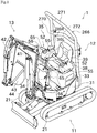
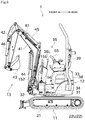
- FIG. 1 is a side view illustrating an overall structure of a revolving work vehicle 1 according to one embodiment of the present invention.
- the revolving work vehicle (work vehicle) 1 illustrated in, e.g., FIGs. 1 and 6 is a small backhoe, which includes a lower traveling body 11 and an upper revolving body 12 as main elements.
- the lower traveling body 11 includes left and right paired crawler traveling devices 21 and hydraulic motors 22 configured to drive the crawler traveling devices 21. As illustrated in FIG. 7 , the hydraulic motors 22 are respectively disposed in the left and right crawler traveling devices 21. By individually driving the left and right crawler traveling devices 21 in various directions at various speeds, it is possible to drive the lower traveling body 11 so that the lower traveling body 11 can travel straight forward or backward or make a turn, for example.
- the upper revolving body 12 includes a revolving frame 31, an engine 33, a hydraulic pump unit 34, an engine hood 38, a steering unit 35, and a work device 13.
- the revolving frame 31 is disposed above the lower traveling body 11.
- the revolving frame 31 is supported by the lower traveling body 11 such that the revolving frame 31 is turnable about a vertical axis.
- the revolving frame 31 can be driven by a revolving motor 32 so that the revolving frame 31 turns relative to the lower traveling body 11.
- the engine 33 is a diesel engine, for example.
- the engine 33 is disposed in a rear portion of the revolving frame 31.
- the hydraulic pump unit 34 is driven by the engine 33 to generate hydraulic force required for the revolving work vehicle 1 to travel and to perform work.
- the engine hood 38 covers and protects an upper surface and the like of the engine 33. As illustrated in FIG. 10 , the engine hood 38 has a rear portion coupled to the revolving frame 31 via left and right paired hinges 245 attached to a rear portion of the revolving frame 31.
- the engine hood 38 is turnable about a rotation shaft 245c, which extends in a left-right horizontal direction, relative to the revolving frame 31. Specifically, by turning the engine hood 38 upward and rearward, it is possible to open the engine hood 38. Meanwhile, by turning the engine hood 38 in a reverse direction, it is possible to close the engine hood 38.
- the steering unit 35 includes a driver's seat 39 on which an operator can sit, a steering box 152 disposed in a standing manner in front of the driver's seat 39, and various manipulation members.
- the manipulation members include left and right paired traveling manipulation levers (traveling levers) 36L and 36R supported by the steering box 152, work manipulation levers 65 respectively disposed on the left and right sides of the driver's seat 39, a traveling speed stage changing switch (traveling speed stage changing device) 155, and a power takeoff pedal (foot pedal) 156, for example.
- the work manipulation lever 65 corresponds to a manipulation lever. The operator can manipulate the manipulation members to give various instructions to the revolving work vehicle 1.
- the steering box 152 is disposed to protrude upward from a floor that is in front of the driver's seat 39.
- the steering box 152 has an upper surface on which the traveling speed stage changing switch 155, the traveling manipulation levers 36L and 36R, and various display devices are arranged.
- the traveling manipulation levers 36L and 36R are disposed side by side in a left-right direction in a portion of the upper surface of the steering box 152, the portion being close to the driver's seat 39 and to the center in the left-right direction.
- the two traveling manipulation levers 36L and 36R are arranged close to each other in the left-right direction, and are supported such that the traveling manipulation levers 36L and 36R protrude upward from the upper surface of the steering box 152.
- the operator can tilt the left and right traveling manipulation levers 36L and 36R forward or rearward to give an instruction to cause the left and right crawler traveling devices 21 to move forward or backward.
- the traveling speed stage changing switch 155 is an electric switch, specifically, a rocker switch whose fulcrum shaft extends in the left-right direction.
- the operator can push an end of the traveling speed stage changing switch 155 to change the posture of the switch like a seesaw.
- the traveling speed stage changing switch 155 is brought into a posture with its rear end tilted downward, the traveling speed stage changing switch 155 is turned on and the contact of the switch is closed.
- the traveling speed stage changing switch 155 is brought into a posture with its front end tilted downward, the traveling speed stage changing switch 155 is turned off and the contact of the switch is opened.
- the operator may turn on the traveling speed stage changing switch 155 to select a high-speed stage (second speed stage). Meanwhile, the operator may turn off the traveling speed stage changing switch 155 to select a low-speed stage (first speed stage).
- the power takeoff pedal 156 is disposed on the left of the steering box 152 and a little above the floor that is in front of the driver's seat 39.
- the operator steps on the power takeoff pedal 156 with his/her foot to drive an attachment work machine (e.g., an attachment for mowing work), which is not illustrated.
- an attachment work machine e.g., an attachment for mowing work
- a first port 181 and a second port 182 for supplying operating oil used to drive the attachment work machine are provided in suitable positions of the revolving work vehicle 1.
- the first port 181 and the second port 182 are disposed in a boom 41 of the work device 13, which will be described later.
- the revolving work vehicle 1 includes a direction selector valve configured to switch the direction of operating oil from one to another.
- the power takeoff pedal 156 causes displacement of the direction selector valve via a link mechanism (not illustrated) including an arm, a rod, and the like. The details of the direction selector valve will be described later. This configuration allows the first port 181 or the second port 182 to eject the operating oil, in response to operator's stepping on the power takeoff pedal 156 forward or rearward.
- the work device 13 includes the boom 41, an arm 42, a bucket 43, a boom cylinder 44, an arm cylinder 45, and a bucket cylinder 46.
- the boom 41, the arm 42, and the bucket 43 are respectively coupled to the hydraulic cylinders.
- By expanding and contracting the hydraulic cylinders it is possible to perform various kinds of work, such as excavation with the bucket 43.
- the boom 41 is an elongated member having an end turnably supported by a front portion of the upper revolving body 12. To the boom 41, the boom cylinder 44 is attached. By expanding and contracting the boom cylinder 44, the boom 41 can be turned.
- the arm 42 is an elongated member having an end turnably supported by a distal end of the boom 41. To the arm 42, the arm cylinder 45 is attached. By expanding and contracting the arm cylinder 45, the arm 42 can be turned.
- the bucket 43 is a container-shaped member having an end turnably supported by a distal end of the arm 42. To the bucket 43, the bucket cylinder 46 is attached. By expanding and contracting the bucket cylinder 46, the bucket 43 can be turned for a scooping motion or a damping motion.
- FIG. 8 is a view schematically illustrating the hydraulic circuit of the revolving work vehicle 1.
- the hydraulic pump unit 34 includes two variable displacement type hydraulic pumps 34a and 34b and an auxiliary hydraulic pump 34c.
- the revolving work vehicle 1 includes a first hydraulic circuit 9a and a second hydraulic circuit 9b.
- the first hydraulic circuit 9a is supplied with operating oil from the hydraulic pump 34a disposed on a first side
- the second hydraulic circuit 9b is supplied with operating oil from the hydraulic pump 34b disposed on a second side.
- the first hydraulic circuit 9a is connected to a hydraulic motor 22L for driving the crawler traveling device 21 disposed on the left side of the vehicle body.
- a direction selector valve 191 is disposed at a location between the hydraulic motor 22L and an ejection port of the hydraulic pump 34a.
- the second hydraulic circuit 9b is connected to a hydraulic motor 22R for driving the crawler traveling device 21 disposed on the right side of the vehicle body and to an attachment cylinder 90 for driving an attachment work machine.
- the attachment cylinder 90 is a double-acting cylinder, and is connected to the first port 181 and second port 182, which have been described above.
- a direction selector valve 192 is disposed at a location between an ejection port of the hydraulic pump 34b and the hydraulic motor 22R.
- a direction selector valve 93 is disposed at a location between the ejection port of the hydraulic pump 34b and the attachment cylinder 90.
- first hydraulic circuit 9a and the second hydraulic circuit 9b are connected with other hydraulic actuators for driving the work device 13 and the like.
- the direction selector valves 191 and 192 which are respectively connected to the left and right hydraulic motors 22L and 22R, each include a spool. Displacement of the spool from a neutral position, where pressure oil supply does not take place, toward one side causes a corresponding one of the hydraulic motors 22L and 22R to rotate forward. Meanwhile, displacement of the spool from the neutral position toward the other side causes a corresponding one of the hydraulic motors 22L and 22R to rotate in a reverse direction.
- the paired traveling manipulation levers 36L and 36R can be used to individually give, to the left and right crawler traveling devices 21, an instruction to travel forward, travel backward, or stop.
- the operator may tilt the traveling manipulation levers 36L and 36R forward from neutral positions to give an instruction to travel forward. Meanwhile, the operator may tilt the traveling manipulation levers 36L and 36R rearward from the neutral positions to give an instruction to travel backward.
- the revolving work vehicle 1 includes traveling manipulation lever remote controlling valves 95L and 95R, which are respectively provided for the paired traveling manipulation levers 36L and 36R.
- Each of the traveling manipulation lever remote controlling valves 95L and 95R has two output ports.
- Each of the traveling manipulation lever remote controlling valves 95L and 95R is configured to feed, to one of the ports corresponding to a direction (forward/backward) in which a corresponding one of the traveling manipulation levers 36L and 36R is manipulated, operating oil at a pressure corresponding to an amount by which the corresponding one of the traveling manipulation levers 36L and 36R is manipulated.
- the above-described direction selector valves 191 and 192 respectively have pilot ports, which are subjected to pilot pressures outputted from the traveling manipulation lever remote controlling valves 95L and 95R.
- the spools of the direction selector valves 191 and 192 are displaced in a direction and by an amount corresponding to the traveling direction and the traveling speed instructed with the traveling manipulation levers 36L and 36R. This can cause the hydraulic motors 22L and 22R to rotate in the direction and at the speed in accordance with the instruction given by the operator.
- the direction selector valve 93 has a spool connected to the power takeoff pedal 156 via the above-described link mechanism.
- the spool of the direction selector valve 93 is displaced in a direction corresponding to the direction instructed with the power takeoff pedal 156 and by an amount corresponding to the manipulation amount of the power takeoff pedal 156. This can cause the attachment cylinder 90 to operate in the direction and by the amount in accordance with the instruction given by the operator.
- the hydraulic pump unit 34 includes not only the hydraulic pumps 34a and 34b but also the auxiliary hydraulic pump 34c configured to adjust outputs from the hydraulic motors 22.
- the auxiliary hydraulic pump 34c can feed operating oil to a swash-plate driving mechanism, which is configured to adjust the angles of movable swash plates of the hydraulic motors 22L and 22R. Between the driving mechanism and the hydraulic motors 22L and 22R, an electromagnetic valve 194 for supplying or interrupting operating oil is provided.
- the electromagnetic valve 194 is electrically connected to the traveling speed stage changing switch 155. When the operator turns on the traveling speed stage changing switch 155, the electromagnetic valve 194 is opened. Meanwhile, when the operator turns off the traveling speed stage changing switch 155, the electromagnetic valve 194 is closed.
- the traveling speed stage changing switch 155 When the traveling speed stage changing switch 155 is turned off, the electromagnetic valve 194 is closed, and accordingly operating oil from the auxiliary hydraulic pump 34c is not supplied to the swash-plate driving mechanism. In this case, inclination angles of the movable swash plates in the hydraulic motors 22 are increased. As a result, the hydraulic motors 22 are driven at a speed corresponding to the first speed stage.
- the traveling speed stage changing switch 155 When the traveling speed stage changing switch 155 is turned on, the electromagnetic valve 194 is opened, and accordingly operating oil from the auxiliary hydraulic pump 34c is supplied to the swash-plate driving mechanism. Consequently, the inclination angles of the movable swash plates in the hydraulic motors 22 are reduced. As a result, the hydraulic motors 22 are driven at a speed corresponding to the second speed stage.
- FIG. 9 is a partial enlarged view illustrating a configuration of the traveling speed stage changing switch 155.
- the traveling speed stage changing switch 155 is positioned on the left of the traveling manipulation lever 36L in a width direction of the steering box 152 (i.e., in the left-right direction of the vehicle body). Namely, the traveling speed stage changing switch 155 is positioned so as to be shifted from the traveling manipulation levers 36L and 36R in the left-right width direction of the steering box 152. With this arrangement, the operator can manipulate the traveling manipulation levers 36L and/or 36R with right hand and the traveling speed stage changing switch 155 with left hand at the same time. Alternatively, the traveling speed stage changing switch 155 may be positioned on the right of the traveling manipulation lever 36R.
- the traveling speed stage changing switch 155 is arranged at a location that is on the left side of the upper surface of the steering box 152 and that is slightly close to the center of the upper surface of the steering box 152. With this arrangement, the operator can easily manipulate the traveling speed stage changing switch 155 either with left or right hand.
- the upper surface (top surface) of the traveling speed stage changing switch 155 has a rear-side portion indicating "ON” mark thereon and a front-side portion indicating "OFF” mark thereon. With this, the operator can easily determine which of the sides of the traveling speed stage changing switch 155 to push to turn on or off the traveling speed stage changing switch 155.
- the on-side portion of the top surface of the traveling speed stage changing switch 155 has a light transmitting portion 157.
- the traveling speed stage changing switch 155 internally includes a lamp (display device) 58 at a location where the light transmitting portion 157 resides.
- the lamp 58 can be configured to be illuminated in response to turning-on of the traveling speed stage changing switch 155. With this, the operator can easily check whether the traveling speed stage changing switch 155 is on or off even in dark environment (e.g., even at night).
- a small picture (icon) indicating a high speed stage is depicted on a portion of the upper surface of the traveling speed stage changing switch 155 in which portion the light transmitting portion 157 resides. This can clearly indicate, to the operator, a relation between the posture of the traveling speed stage changing switch 155 and the traveling speed stage. In addition, while the lamp 58 is illuminated, the icon emerges against light. This enables the operator to more easily check whether the traveling speed stage changing switch 155 is on or off.
- the traveling speed stage changing switch 155 is used to change the speed stage from one to another. Therefore, it is not necessary to impart the switching function of the speed stage to the power takeoff pedal 156.
- simple manipulation of the revolving work vehicle 1 to which an attachment work machine including a double-acting hydraulic actuator is attached can be achieved. Specifically, stepping on the power takeoff pedal 156 toward the first side drives the attachment work machine toward the first side, whereas stepping on the power takeoff pedal 156 toward the second side drives the attachment work machine toward the second side.
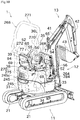
- console boxes 52 provided with the above-described work manipulation levers 65.
- the driver's seat 39 on which the operator can sit, is disposed at the center in the left-right direction of an upper surface of the upper revolving body 12.
- the driver's seat 39 is illustrated with the dashed lines in order to clearly indicate a belt 372 (describer later) and other elements.
- the driver's seat 39 is sandwiched by the left and right paired console boxes 52.
- the driver's seat 39 and the console boxes 52 are disposed on an upper surface of the engine hood 38 of the upper revolving body 12.
- each of the console boxes 52 includes a box body 55, the work manipulation lever 65 (described above), the lock lever 56, and an armrest 57.
- the console box 52 supports the work manipulation lever 65 and the lock lever 56.
- the box body 55 has a hollow structure for covering and protecting various mechanisms disposed therein (e.g., a lock cam 79, a pilot valve 77, and an electric switch 94, which will be describer later).
- various mechanisms disposed therein e.g., a lock cam 79, a pilot valve 77, and an electric switch 94, which will be describer later).
- each of the left and right console boxes 52 includes the pilot valve 77 disposed inside the box body 55. As illustrated in FIG. 11 , each of the left and right pilot valves 77 has one input port and four output ports.
- the input ports of the pilot valves 77 are connected to ejection ports of the hydraulic pumps included in the above-described hydraulic pump unit 34 via pipes (not illustrated). As illustrated in FIGs. 10 and 11 , the hydraulic pumps and the pilot valves 77 are connected to each other via an operating oil path including a solenoid valve (lock unit) 264 of the revolving work vehicle 1. As illustrated in FIG. 11 , between the hydraulic pumps of the hydraulic pump unit 34 and the solenoid valve 264, a relief valve for releasing pressure is provided.
- the output ports of the pilot valves 77 are connected to a control valve 284 of the revolving work vehicle 1 via pipes (not illustrated).
- Each of the pilot valves 77 opens or closes a space between the input port and the output ports according to operator's manipulating a corresponding one of the work manipulation levers 65 forward, rearward, leftward, or rightward.
- operating oil is fed from the pilot valve 77 to the control valve 284.
- the control valve 284 includes a plurality of spools for driving or stopping the hydraulic actuators of the work device 13 and the like.
- the spools of the control valve 284 are displaced by pilot pressures of streams of operating oil from the pilot valves 77. This can actuate the hydraulic actuators to cause the upper revolving body 12 to revolve and/or to cause the work device 13 to perform various kinds of work.
- the box bodies 55 are turnably supported, via support shafts 69 extending in the left-right direction, on base members 60 (described later) fixed on the upper surface of the engine hood 38.
- the operator can manipulate each of the lock levers 56 as appropriate to switch the posture of a corresponding one of the console boxes 52 between a first posture P1 and a second posture P2.
- the first posture P1 is indicated by the solid lines
- the second posture P2 is indicated by the dashed lines.
- the first posture P1 of each of the console boxes 52 in a state where the engine hood 38 is closed is a substantially horizontal posture, which is a normal posture allowing the operator to manipulate a corresponding one of the work manipulation levers 65.
- the second posture P2 is achieved as a result of upward and rearward movement of the console box 52 from the first posture P1.
- the second posture P2 is selected to temporarily retract the console box 52 into an upward and rearward space so that the operator can get on or off the revolving work vehicle 1.
- a direction in which the console box 52 turns to change its posture from the first posture P1 to the second posture P2 coincides with a direction in which the closed engine hood 38 turns so as to be opened.
- the console boxes 52 respectively have cam mechanisms (described later), each of which is capable of regulating unintentional turning of a corresponding one of the console boxes 52 with respect to the engine hood 38 from the current posture, both in a case where the console box 52 is in the first posture and in a case where the console box 52 is in the second posture.
- Each of the cam mechanisms may be any cam, such as a grooved cam.
- the work manipulation levers 65 and the lock levers 56 are arranged to protrude from the box bodies 55.
- the work manipulation levers 65 are disposed in upper portions of the console boxes 52 such that the work manipulation levers 65 protrude obliquely forward and upward.
- the operator can manipulate the work manipulation lever(s) 65 to give an instruction regarding an operation of the work device 13 or revolving of the upper revolving body 12.
- the lock levers 56 are disposed in lower portions of front surfaces of the console boxes 52 such that the lock levers 56 protrude obliquely forward and upward.
- the lock levers 56 are manipulated to change the postures of the console boxes 52.
- the lock levers 56 are supported by the box bodies 55 such that the lock levers 56 are turnable around axes extending in the left-right horizontal direction. The operator can turn the lock levers 56 to release the cam mechanisms' restriction against the turning so that the box bodies 55 (in other words, the console boxes 52) can turn from the first posture P1 to the second posture P2, or vice versa.
- the hydraulic circuit in the revolving work vehicle 1 has a lock function to disable manipulation of the work manipulation levers 65 while the console boxes 52 are in the second posture P2.
- the lock function can be achieved by controlling operating oil supply to the pilot valves 77, which are configured to be opened or closed in response to manipulation of the work manipulation levers 65, in the following manner. That is, if a sensor and/or the like detects that at least one of the console boxes 52 is in the second posture P2, the supply of the operating oil to the pilot valves 77 is interrupted.
- the operator in the revolving work vehicle 1 manipulates the work manipulation levers 65 after bringing the console boxes 52 into the first posture P1. Meanwhile, when the operator is to get on or off the revolving work vehicle 1, the operator brings at least one of the console boxes 52 into the second posture P2 to retract the at least one of the console boxes 52 so that the operator's body is not interfered with by the at least one of the console boxes 52.
- the structures of the left and right console boxes 52 are symmetric to each other, and thus are substantially identical to each other. Therefore, the following will representatively describe the console box 52 disposed on the left viewed from the operator sitting on the driver's seat 39.
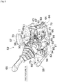
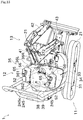
- FIG. 3 is a side perspective view of the console box 52 being in the first posture P1
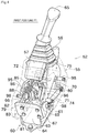
- FIG. 4 is a back perspective view of the console box 52 being in the first posture P1.
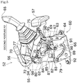
- FIG. 5 is a side perspective view of the console box 52 being in the second posture P2.
- FIGs. 3 to 5 shows a perspective view of the box body 55 depicted with the dashed lines to show details of an internal structure of the console box 52.
- the console box 52 includes not only the above-described configuration but also the base member 60, the support shaft 69, a main arm 70, a first reinforcing member 71, a second reinforcing member 72, a mount plate 75, a cam arm shaft 80, a cam arm 81, and a helical torsion spring 86 as main elements.
- the base member 60 is made of a plate-shaped member bent in a substantial U-shape viewed from the back side.
- the base member 60 has a necessary and sufficient width in the left-right direction, and has an internal space whose front and upper portions are opened.
- the inside (inner side/inward) in the left-right direction means a side close to the center (the center in the left-right direction) of the base member 60 at which the width of the base member 60 is divided into two equal parts
- the outside (outer side/outward) means a side located away from the center, unless otherwise explained.
- the center in the width direction of the base member 60 substantially coincides with the center in the width direction of the box body 55.
- the base member 60 includes a bottom plate 64, a first plate (guide member) 66, and a second plate 67.
- the bottom plate 64 is fixed to the upper surface of the engine hood 38 (see FIG. 1 ) via a bolt, which is a fastening member.
- the first plate 66 vertically extends from one of the left and right ends of the bottom plate 64 in a standing manner.
- the first plate 66 has a cam groove 88, which will be described in detail later.
- the second plate 67 vertically extends from the other of the left and right ends of the bottom plate 64 in a standing manner. The upper end of the second plate 67 is lower in height than that of the first plate 66.
- the base member 60 has a rear portion to which a back surface plate 63 is fixed. To the back surface plate 63, a first support plate 61 is fixed. The first support plate 61 is disposed above the second plate 67, and faces the first plate 66 in the left-right direction.
- the support shaft 69 is rotatably supported.
- the support shaft 69 is a thin elongated cylindrical member, and is arranged such that its longitudinal direction extends in the left-right direction.
- the support shaft 69 is a rotation shaft of the above-described box body 55 (namely, a console rotating body, which will be described later).
- the support shaft 69 has an end which is away from the first plate 66 and to which the main arm 70 is fixed.
- the main arm 70 is a plate-shaped member substantially inverted V-shaped in a lateral side view.
- the main arm 70 has a side which faces the first plate 66 and to which the first reinforcing member 71 for enhancing the rigidity is fixed.
- the armrest 57 is attached to the first reinforcing member 71.
- the main arm 70 and the second plate 67 are coupled to each other via a gas damper 74, which is a biasing member.
- the gas damper 74 gives the main arm 70 biasing force in a stretching direction. Namely, the main arm 70 is subjected to biasing force for turning the main arm 70 upward around the support shaft 69.
- the main arm 70 and the first reinforcing member 71 have upper ends to which the mount plate 75 is fixed. As illustrated in FIG. 3 , the pilot valve 77 is fixed to the mount plate 75. Above the pilot valve 77, the work manipulation lever 65 is disposed.
- the revolving work vehicle 1 includes the control valve 284, which is configured to change the supply mode of the operating oil to various actuators used for traveling and/or work.
- the pilot valve 77 is connected to the control valve 284 via a pipe (not illustrated) having flexibility.
- the pilot valve 77 controls a pilot hydraulic pressure with respect to the control valve 284. Consequently, it is possible to cause the upper revolving body 12 to revolve and/or perform a scooping motion with the bucket 43, for example.
- the second reinforcing member 72 is fixed so as to connect the mount plate 75 with the main arm 70.
- a second support plate 62 is fixed to the second reinforcing member 72.
- the second support plate 62 is positioned to face the main arm 70 in the left-right direction.
- the second support plate 62 is disposed in front of the first plate 66.
- a support bar 95 is fixed to the first reinforcing member 71. While the console box 52 is in the first posture P1, the support bar 95 is bent as appropriate to detour an upper portion of the first plate 66 and reach an outer side in the left-right direction of the first plate 66.
- the support bar 95 has a distal end to which a cylindrical attachment boss 98 having a female thread is fixed.
- Two attachment bosses 98 which have identical structures to that of the above-described attachment boss 98, are fixed to the main arm 70. Also, one attachment boss 98, which has an identical structure to that of the above-described attachment boss 98, is fixed to the second support plate 62. These attachment bosses 98 are arranged to protrude outward in the left-right direction. The attachment bosses 98 are fixed to the box body 55, which is made of a synthetic resin, via bolts, which are fastening members.
- the box body 55 is made of upper and lower divided members.
- the box body 55 is fixed to the attachment bosses 98 via the bolts with its upper and lower divided members combined to each other.
- the box body 55 has a lower surface with an opening through which the base member 60 protrudes.
- the box body 55 also has suitable openings through which the work manipulation lever 65, the lock lever 56, and the armrest 57 respectively protrude externally.
- the cam arm shaft 80 is rotatably supported.
- the cam arm shaft 80 is a thin elongated cylindrical member, and is arranged such that its longitudinal direction extends in the left-right direction.
- the cam arm shaft 80 is located in front of the base member 60.
- the lock lever 56 is fixed to the cam arm shaft 80.
- the lock lever 56 has a curved shape. In the first posture P1, a distal end of the lock lever 56 is directed obliquely upward.
- the cam arm shaft 80 has an end that is close to the first plate 66 and that has the cam arm 81 fixed thereto.
- the cam arm 81 includes an arm body 82, a guide projection (insertion portion) 83, and a spring holding member (inwardly protruding portion) 84.
- the arm body 82 is a thin elongated plate-shaped member. While the console box 52 is in the first posture P1, the arm body 82 extends substantially rearward from the cam arm shaft 80, and a distal end of the arm body 82 is inserted into an internal space of the base member 60. The arm body 82 is positioned close to an inner side in the left-right direction of the first plate 66. A thickness direction of the plate of the arm body 82 coincides with a thickness direction of the first plate 66.
- the guide projection 83 is fixed to the distal end of the arm body 82, and protrudes outward in the left-right direction therefrom.
- the first plate 66 has the cam groove 88 that is penetrated through the first plate 66. Into the cam groove 88, the guide projection 83 is inserted.
- the cam groove 88 can guide the distal end of the cam arm 81.
- the cam arm 81 described above and the first plate 66 constitute the lock cam 79. Both in a case where the box body 55 is in the first posture P1 and in a case where the box body 55 is in the second posture P2, the lock cam 79 can lock turning of the box body 55 (in other words, the console rotating body, which will be described later) both in the first posture P1 and in the second posture P2.
- the arm body 82 has an intermediate portion in its longitudinal direction at which a projection 85 is integrally formed.
- the projection 85 extends substantially vertically with respect to the longitudinal direction of the arm body 82.
- a spring holding member 84 is fixed to the projection 85.
- the spring holding member 84 is a small member protruding inward in the left-right direction (i.e., in a direction reverse to the direction in which the guide projection 83 protrudes from the arm body 82) from the arm body 82.
- the helical torsion spring 86 is disposed to connect a suitable portion of the first plate 66 to the spring holding member 84.
- the helical torsion spring 86 is positioned so that an axis of a coil portion, which is made of a wound spring wire, coincides with the left-right direction.
- the spring wire of the helical torsion spring 86 has a first end directed outward in the left-right direction and inserted into a small hole in the first plate 66.
- the spring wire has a second end directed inward in the left-right direction so as to be inserted into a small hole in the spring holding member 84.
- the cam groove 88 has a substantially constant width, and is smoothly curved in a substantial S-shape.
- the cam groove 88 has a section that is away from the cam arm shaft 80 and that is curved to extend downward and have an end directed substantially upward. A portion of the cam groove 88 that is close to this end corresponds to a first lock portion 91 of the cam groove 88.
- the cam groove 88 has another section that is close to the cam arm shaft 80 and that is bent at a substantially right angle and is directed substantially upward. The bent portion of the cam groove 88 corresponds to a second lock portion 92 of the cam groove 88.
- the second reinforcing member 72 has an electric switch 94 fixed thereto.
- the electric switch 94 includes a contact maker. In a state where the cam arm 81 is at the position shown in FIG. 3 , the contact maker is pushed by the arm body 82. Meanwhile, when the cam arm 81 turns clockwise from the position shown in FIG. 3 viewed from the second plate 67 side, the pushing is released.
- the electric switch 94 serves as a sensor for detecting turning of the cam arm 81 in this manner.
- the console box 52 of the present embodiment has the configuration described above, the console box 52 can be deemed as having a configuration in which a console rotating body is turnably supported by a base body.
- the base body includes the base member 60 and the back surface plate 63, for example.
- the console rotating body includes the work manipulation lever 65, the box body 55, the lock lever 56, the armrest 57, the main arm 70, the first reinforcing member 71, the second reinforcing member 72, the mount plate 75, and the second support plate 62, for example.
- changing of the posture of the box body 55 substantially means changing of the posture of the console rotating body.
- FIG. 3 shows a state where the box body 55 is in the first posture P1.
- the guide projection 83 disposed at the distal end of the cam arm 81 is at the first lock portion 91 of the cam groove 88.
- the helical torsion spring 86 generates spring force in a direction for expanding a distance between the opposed ends of the spring wire.
- the spring force thus generated acts in a direction for causing the cam arm 81 to turn counterclockwise viewed from the second plate 67 side. Consequently, the cam arm 81 is held with the guide projection 83 being at the first lock portion 91.
- the gas damper 74 constantly biases the main arm 70.
- force for lifting up the console rotating body to achieve the second posture P2 is applied.
- the console rotating body (box body 55) would not turn. In this manner, turning locking in the first posture P1 is achieved.
- the fulcrum point for the force between the opposed ends of the spring wire of the helical torsion spring 86 and the cam arm shaft 80 is passed over. Thereafter, the spring force of the helical torsion spring 86 acts in a direction for causing the cam arm 81 to turn clockwise viewed from the second plate 67 side.
- the console rotating body is lifted up by the biasing force of the gas damper 74, and accordingly the guide projection 83 of the cam arm 81 passes through the downwardly projecting curved portion of the cam groove 88, so as to move toward the second lock portion 92.
- the biasing force of the gas damper 74 is exerted continuously, and accordingly the console rotating body turns about the support shaft 69.
- the console rotating body is biased by the gas damper 74.
- the gas damper 74 it is possible to suppress or reduce a variation in biasing force over the whole range of the turning stroke of the console rotating body.
- the operator can attain stable assist force to turn the console rotating body to change the posture of the box body 55 from the first posture P1 to the second posture P2.
- the cam groove 88 is formed in a smooth curved line at least in its intermediate portion, the cam arm 81 and the like can move smoothly. This makes it possible to smoothly change the posture of the console rotating body.
- the second posture P2 shown in FIG. 5 is attained.
- the spring force of the helical torsion spring 86 acts in a direction for causing the cam arm 81 to turn clockwise viewed from the second plate 67 side. Consequently, the cam arm 81 is held with the guide projection 83 being at the second lock portion 92, which is bent.
- the turning stroke of the console rotating body is restricted by contact between a stopper 96, which is provided in the first reinforcing member 71, and an upper end of the back surface plate 63.
- the lock lever 56 is biased by the helical torsion spring 86, rather than by a tension spring or the like. Therefore, it is possible to achieve biasing force without causing great deformation in the coil portion.
- the console box 52 having a compact configuration can be easily achieved.
- a plurality of pipes (not illustrated) connected to the pilot valve 77.
- a margin allowing the deformation is required around the pipes.
- the configuration including the helical torsion spring 86 as in the present embodiment is effective.
- this configuration is suitable for a small revolving work vehicle that cannot include a console box 52 having a large width in a left-right direction due to a restricted turning radius of an upper revolving body 12.
- the coil portion of the helical torsion spring 86 is arranged inward in the left-right direction than is the first plate 66, which has the cam groove 88.
- the coil portion of the helical torsion spring 86 is positioned within the distance in the left-right direction from the first plate 66 to the spring holding member 84.
- the center of the coil portion is substantially in parallel with the axis line of the cam arm shaft 80. There is no member (e.g., a guide shaft) inserted into the coil portion. This makes it possible to determine the positions of the opposed ends of the spring wire more flexibly.
- the spring wire extends substantially upward from a portion where the spring wire is connected to the first support plate 61, and is then connected to the coil portion.
- the spring wire extends substantially upward also from a portion where the spring wire is connected to the spring holding member 84, and is then connected to the coil portion.
- the coil portion is disposed above the arm body 82.
- the helical torsion spring 86 extends to connect the first plate 66 with the spring holding member 84 while substantially detouring an upper portion of the arm body 82.
- the spring wire of the helical torsion spring 86 extends obliquely upward from the position where the spring wire is connected to the first support plate 61, and is then connected to the coil portion.
- the coil portion is positioned above the portion where the spring wire is attached to the first support plate 61.
- the spring wire extends downward so as to be connected to the first support plate 61.
- the revolving work vehicle 1 of the present embodiment includes an engine hood switch 275.
- the engine hood switch 275 is attached to a suitable position on the revolving frame 31.
- the engine hood switch 275 includes a contact maker, which is positioned so as to be pushed by a small actuating member fixed to the inner wall of the engine hood 38 when the engine hood 38 is closed.
- the engine hood switch 275 is configured as below. That is, the contact of the engine hood switch 275 is closed when the contact maker is pushed, whereas the contact of the engine hood switch 275 is opened when the contact maker is not pushed. With this configuration, the engine hood switch 275 is capable of detecting whether the engine hood is opened or closed.
- the engine hood switch 275 outputs, to the solenoid valve 264, the detection result regarding whether the engine hood 38 is opened or closed.
- each of the electric switches 94 is respectively attached to suitable positions inside the box bodies 55 of the left and right console boxes 52.
- Each of the electric switches 94 includes a contact maker, which is positioned at a location where the electric switch 94 is pushed by a suitable member (e.g., the cam arm 81, which is described above) while the console box 52 is in the first posture P1.
- a suitable member e.g., the cam arm 81, which is described above
- Each of the electric switches 94 is configured as below. That is, the contact of the electric switch 94 is closed when the contact maker is pushed, whereas the contact of the electric switch 94 is opened when the contact maker is not pushed.
- each of the electric switches 94 is capable of detecting the posture of its corresponding console box 52.
- the left and right electric switches 94 are electrically connected to the solenoid valve 264, and output, to the solenoid valve 264, the detection results regarding the postures of the console boxes 52.
- the solenoid valve 264 is opened when all of the contacts of the left and right electric switches 94 and the engine hood switch 275 are closed. Meanwhile, the solenoid valve 264 is closed when at least one of the contacts of the left and right electric switches 94 and the engine hood switch 275 is opened.
- the solenoid valve 264 supplies operating oil to the pilot valves 77 to enable manipulation of the work device 13 and/or the like with the work manipulation levers 65. Meanwhile, in cases other than the above, the solenoid valve 264 interrupts supply of the operating oil to the pilot valves 77 to disable manipulation of the work device 13 and/or the like with the work manipulation levers 65.
- the revolving frame 31 has a rear portion to which a safety frame (safety device) 266 is fixed.
- the safety frame 266 is configured to secure a space around the operator if the revolving work vehicle 1 turns over.
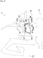
- FIG. 10 shows a perspective view of the safety frame 266 depicted with the dashed lines.
- the safety frame 266 is of a two columnar type, and has an inverted U-shape in a front view.
- the safety frame 266 has two supporting columns 270, a first coupling portion 271, and a second coupling portion (regulating portion) 272.
- Each of the supporting columns 270 is a member that is thin and elongated substantially in the top-bottom direction.
- the supporting columns 270 which are provided in a pair, are disposed on the left and right sides of the upper revolving body 12, respectively.
- the supporting columns 270 have lower portions that are respectively fixed to rear diagonal left and right portions of the revolving frame 31 in the rear of the engine 33.
- the two supporting columns 270 are adequately spaced from each other in the left-right direction of the upper revolving body 12. Therefore, the supporting columns 270 would not hinder opening/closing of the engine hood 38 and changing of the postures of the console boxes 52.
- the first coupling portion 271 is a member that is thin and elongated in the left-right direction.
- the first coupling portion 271 is integrally formed with the supporting columns 270 such that the first coupling portion 271 connects upper ends of the left and right supporting columns 270 with each other.
- the second coupling portion 272 is a member that is thin and elongated substantially in the left-right direction.
- the second coupling portion 272 is provided below the first coupling portion 271 such that the second coupling portion 272 connects the left and right supporting columns 270 with each other.
- the second coupling portion 272 has a curved portion whose longitudinal center extends forward toward its opposed ends (i.e., toward connecting portions between the second coupling portion 272 and the supporting columns 270).
- FIG. 12 shows a hatched cross section of the second coupling portion 272 cut in a virtual plane including an arched trajectory of the distal ends of the work manipulation levers 65 observed when the console boxes 52 are caused to turn.
- the first virtual circle C1 is defined by a radius equal to a distance between the rotation shaft 245c of the engine hood 38 and the distal end of either one of the work manipulation levers 65 being in the first posture P1 and by a center that is the rotation shaft 245c.
- focus on a second virtual circle C2 defined by a radius equal to a distance between the rotation shaft 245c and the distal end of either one of the work manipulation levers 65 being in the second posture P2 and by a center that is the rotation shaft 245c.
- the second coupling portion 272 is arranged inside the first virtual circle C1 and outside the second virtual circle C2.
- the third virtual circle C3 is defined by a radius equal to a distance between the support shaft 69, which is a turning center of the console box 52, and the distal end of either one of the work manipulation levers 65 and by a center that is the support shaft 69 in a state where the engine hood 38 is closed.
- the second coupling portion 272 is arranged outside the third virtual circle C3.
- Arranging the second coupling portion 272 brings about the following effects. That is, in a state where the console boxes 52 are in the first posture P1, even if an attempt to turn the engine hood 38 takes place, it is impossible to open the engine hood 38, since the work manipulation levers 65 are interfered with by the second coupling portion 272. However, in a state where the engine hood 38 is closed, the console boxes 52 in the first posture P1 can be turned into the second posture P2.
- the electric switches 94 detect that the console boxes 52 have been turned into the second posture P2. Consequently, the solenoid valve 264 is closed, and accordingly manipulation of the left and right work manipulation levers 65 is disabled.
- the solenoid valve 264 is closed, and accordingly manipulation of the left and right work manipulation levers 65 is disabled.
- the operator holds a suitable portion of the engine hood 38 with his/her hand and turns the engine hood 38 upward and rearward.
- the engine hood 38 is caused to turn to the position indicated by the dashed lines in FIG. 12 with its front portion opened. This allows easy access to the inside of the engine hood 38 (e.g., to the engine 33).
- the following situation may be considered. That is, the operator opens the engine hood 38 with the console boxes 52 being in the first posture P1 by mistake, and consequently the work manipulation lever(s) 65 come(s) into contact with the second coupling portion 272, so that the pilot valves 77 are actuated.
- the engine hood switch 275 detects that the engine hood 38 is opened, and opens its contact.
- the solenoid valve 264 has been turned into the closed state. Namely, before the work manipulation lever(s) 65 come(s) into contact with the second coupling portion 272, manipulation of the work manipulation levers 65 is disabled. Thus, it is possible to prevent the work device 13 and/or the like from operating.
- the closing operation of the engine hood 38 that is opened may be performed in a manner reverse to that of the above.
- the operator first closes the engine hood 38.
- the console boxes 52 are in the second posture P2.
- the engine hood switch 275 detects the closed state of the engine hood 38, and closes its contact.
- the operator turns the left and right console boxes 52 being in the second posture P2 into the first posture P1.
- the left and right electric switches 94 detect the first posture P1, and close their contacts. Consequently, manipulation of the work manipulation levers 65 is enabled by the solenoid valve 264.
- the second coupling portion 272 of the safety frame 266 inhibits opening or closing of the engine hood 38 unless the console boxes 52 are turned into the second posture P2.
- the operator it is possible to certainly make the operator follow the correct procedure for opening or closing the engine hood 38.
- the second coupling portion 272 has the curved portion whose longitudinal center extends forward toward the connecting portions between the second coupling portion 272 and the supporting columns 270. This provides the arrangement of the second coupling portion 272 that would not have the operator sitting on the driver's seat 39 feel constraint. This can provide interior comfort to the operator.
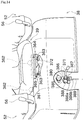
- FIG. 14 is a front perspective view of an unlocking handle 371 and a belt 372 of the first embodiment.
- the engine hood 38 is provided with a lock mechanism 380 capable of holding the engine hood 38 in a closed state.
- the lock mechanism 380 includes the unlocking handle (first handle) 371, which is disposed in a lower portion of the front surface of the engine hood 38.
- the lock mechanism 380 includes not only the unlocking handle 371 but also a supporting boss 385, a hooking plate 386, and a helical torsion spring 387.
- the left and right respectively mean the left and right viewed from the operator sitting on the driver's seat.
- the supporting boss 385 is a hollow cylindrical member, and is fixed to the inner wall of the engine hood 38 via a bracket 388.
- the supporting boss 385 has a shaft hole opened substantially in the front-rear direction.
- Abase portion of the unlocking handle 371, which is bent in an L-shape, is turnably supported by the shaft hole.
- the unlocking handle 371 protrudes forward from the supporting boss 385, passes through a through-hole (not illustrated) of the engine hood 38, and then is bent substantially at 90° to the left.
- the bent portion has a distal end fixed to a grip portion for use in manipulation.
- the hooking plate 386 is a plate-shaped member, and is fixed to an end of the unlocking handle 371 at a location inside the engine hood 38. Thus, the hooking plate 386 turns integrally with the unlocking handle 371.
- the hooking plate 386 has a hooking groove 386a below its turning center.
- the hooking groove 386a is a groove that is thin and elongated in the left-right direction, and has a right end that is opened.
- a thin elongated lock bar 389 is fixed to a suitable member of the revolving frame 31 .
- the lock bar 389 extends substantially upward from the revolving frame 31, and has an end bent in a hook shape. The distal end of the lock bar 389 can be inserted into the hooking groove 386a.
- the hooking plate 386 has an inclined guide portion 386b at a location below the hooking groove 386a.
- the inclined guide portion 386b can turn the hooking plate 386 when pushed by the distal end of the lock bar 389.
- the helical torsion spring 387 is arranged to connect the bracket 388 and the hooking plate 386.
- the helical torsion spring 387 functions as a biasing member.
- the helical torsion spring 387 applies, to the hooking plate 386, spring force in a clockwise direction in a front view, i.e., in a direction for causing the hooking groove 386a to be engaged with the distal end of the lock bar 389.
- the hooking plate 386 turns counterclockwise in a front view against the biasing force of the helical torsion spring 387. This releases the engagement between the hooking groove 386a and the lock bar 389. Consequently, the locking state is released, and accordingly the engine hood 38 becomes ready to be opened.
- the turning stroke of the unlocking handle 371 is restricted by contact between a suitable portion of the hooking plate 386 and the bracket 388.
- the pulling force that the operator applies to the unlocking handle 371 acts to cause the engine hood 38 to turn in an opening direction.
- the unlocking handle 371 serves also as a handle that can be gripped by the operator for lifting up and turning the engine hood 38.
- the opened engine hood 38 is closed in the following manner. That is, just before the engine hood 38 is completely closed, the distal end of the lock bar 389 comes into contact with the inclined guide portion 386b, and consequently the hooking plate 386 turns against the biasing force of the helical torsion spring 387. When the engine hood 38 is completely closed, the lock bar 389 enters the hooking groove 386a, thereby leading to the above-described locked state automatically.
- the driver's seat 39 is attached to an upper portion of the engine hood 38 with a front supporting member 361 and rear supporting members 362. This creates a gap between the driver's seat 39 and the upper surface of the engine hood 38 in the top-bottom direction.
- the front supporting member 361 is made of a metal plate bent in a substantial wide U-shape in a front view.
- the front supporting member 361 has, in its center, a bottom plate fixed at the center in the left-right direction of a front portion of the upper surface of the engine hood 38 with a pair of left and right bolts (fixing members) 363.
- the front supporting member 361 has left and right lateral plates to which substantially U-shaped brackets 364 fixed to a lower surface of the driver's seat 39 can be fixed via a fulcrum shaft 365.
- the left and right paired rear supporting members 362, each of which has a cylindrical vibration isolating rubber, are fixed to a rear portion of the upper surface of the engine hood 38.
- the lower surface of the driver's seat 39 can be attached.
- the belt 372 is a thin elongated strip having opposed ends fixed to buckles that are to be fixed to the engine hood 38.
- the buckles are made of, e.g., a metal or a synthetic resin, and are fixed to the engine hood 38 together with the front supporting member 361 via the above-described bolts 363.
- the belt 372 has an intermediate portion in its longitudinal direction that is made of, e.g., a polyester fiber material and that has flexibility.
- the belt 372 is longer than a distance between the attachment portions (i.e., the bolts 363) at the opposed ends of the belt 372.
- the belt 372 is slightly loosened. Therefore, the belt 372 can be arranged such that the intermediate portion of the belt 372 slightly protrudes forward from the front end of the driver's seat 39 and hangs down forward.
- the belt 372 is easily deformed, and thus hardly hinders the operator who is getting in or off the revolving work vehicle 1 even if the belt 372 comes into contact with him/her.
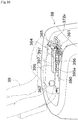
- FIG. 15 is a schematic side view for explaining a function of an engine hood stay 48.
- a stay supporting member 346 is fixed inside a space in the upper revolving body 12 which space is covered with the engine hood 38.
- the stay supporting member 346 is formed in a plate shape, and is arranged such that its thickness direction extends in the left-right direction.
- a guide member 47 In a suitable position of the inner wall of the engine hood 38, a guide member 47 is fixed.
- the guide member 47 has a guide groove 47a that is thin and elongated in the front-rear direction and that is penetrated through the guide member 47.
- the guide groove 47a has a first end that is short and bent.
- the stay supporting member 346 has a rear upper portion by which a first end of the bar-shaped engine hood stay 48 is turnably supported.
- the engine hood stay 48 has a second end inserted into the guide groove 47a of the guide member 47 so as to be slidable along the guide groove 47a.
- the operator performs the following operation as a preparation before opening the engine hood 38. That is, the operator manipulates the lock levers 56 of the left and right console boxes 52 show in, e.g., FIG. 13 to bring the two console boxes 52 into the second posture P2, which is achieved as a result of upward and rearward movement of the console boxes 52. Consequently, manipulation of the work manipulation levers 65 is disabled, as described above.
- the operator holds the unlocking handle 371 with one hand and the belt 372 with the other hand, and pulls the unlocking handle 371 and the belt 372 with both hands.
- the belt 372 is deformable. Therefore, not only a person with big hands but also a person with small hands can firmly hold the belt 372.
- the lock mechanism 380 is unlocked.
- the engine hood 38 turns upward and rearward about the rotation shaft 245c. With the above configuration, force is applied to the engine hood 38 at two locations, specifically, at the unlocking handle 371 and the belt 372.
- the operator can apply stable force to the engine hood 38 with both arms. Therefore, the engine hood 38 can turn smoothly even without a biasing device (assist device) such as a torsion bar.
- the engine hood stay 48 turns, and the distal end of the engine hood stay 48 moves along the guide groove 47a.
- the distal end of the engine hood stay 48 enters the bent portion of the guide groove 47a, as indicated by the dashed lines in FIG. 15 . Consequently, the engine hood stay 48 can pull and hold the engine hood 38 that otherwise tends to tilt rearward.
- the distal end of the engine hood stay 48 enters a short groove connected to the bent portion of the guide groove 47a, and thus the engine hood stay 48 is held at the end of the short groove with a tension. This prevents the engine hood 38 from being closed against the operator's will.
- the engine hood 38 opened as indicated by the dashed lines in FIG. 15 is closed in the following manner. That is, the operator or the like may pull the engine hood stay 48 slightly upward with his/her hand so that the distal end of the engine hood stay 48 is retracted from the above-described short groove of the guide groove 47a. Thereafter, the operator may hold the unlocking handle 371 and the belt 372 to turn the engine hood 38 in a direction reverse to the above.
- the engine hood 38 has two portions that can be held by hands.
- the operator can easily perform opening/closing operation of the engine hood 38 with both hands. Therefore, even for, e.g., a small revolving work vehicle including an engine hood 38 that is difficult to accommodate a torsion bar or the like therein due to its limited space, it is possible to enhance the ease of maintenance thanks to adoption of the configuration of the present embodiment.
- the revolving work vehicle 1 of the present embodiment includes the console boxes 52.
- Each of the console boxes 52 includes the box body 55, the work manipulation lever 65, the lock lever 56, the gas damper 74, and the lock cam 79.
- the box body 55 is turnable between the first posture P1 and the second posture P2, which is achieved as a result of upward movement of the box body 55 from the first posture P1.
- the work manipulation lever 65 is arranged to protrude from the box body 55.
- the lock lever 56 is arranged to protrude from the box body 55, and is configured to be turnable.
- the gas damper 74 biases the box body 55 in a direction for bringing the box body 55 into the second posture P2.
- the lock cam 79 can lock turning of the box body 55 both in the first posture P1 and in the second posture P2.
- the lock cam 79 includes the first plate 66 and the cam arm 81.
- the first plate 66 has the cam groove 88.
- the cam arm 81 is configured to turn integrally with the lock lever 56.
- the cam arm 81 has the guide projection 83 inserted into the cam groove 88.
- the helical torsion spring 86 which is configured to bias the cam arm shaft 80, is arranged to connect the cam arm 81 and the first plate 66.
- the cam arm 81 inverts the direction in which the box body 55 is caused to turn by the biasing force of the helical torsion spring 86.
- the coil portion of the helical torsion spring 86 is arranged closer to the center in the left-right direction of the box body 55 than is the first plate 66.
- the space inside the box body 55 can be effectively used.
- the space closer to the center in the left-right direction of the box body 55 than is the first plate 66 can be effectively used. Consequently, it is possible to easily make the console box 52 compact.
- the cam arm 81 includes the plate-shaped arm body 82 and the spring holding member 84.
- the arm body 82 is arranged closer to the center in the left-right direction of the box body 55 than is the first plate 66.
- the spring holding member 84 protrudes from the arm body 82 toward the center in the left-right direction of the box body 55.
- the first end of the spring wire of the helical torsion spring 86 is attached to the first plate 66, whereas the second end of the spring wire of the helical torsion spring 86 is attached to the spring holding member 84.
- the cam arm 81 can be biased by the helical torsion spring 86, which can contribute greatly to space saving.
- the revolving work vehicle 1 of the present embodiment is configured such that, in a case where the box body 55 is in the first posture P1 and in a case where the box body 55 is in the second posture P2, the coil portion of the helical torsion spring 86 is above a portion of the first plate 66 to which portion the spring wire is attached.
- the spring wire extends downward so as to be connected to the first plate 66. Consequently, the coil portion of the helical torsion spring 86 hardly interferes with other components inside the box body 55. As a result, it is possible to achieve a compact structure.
- the biasing member for biasing the box body 55 in a direction for bringing the box body 55 into the second posture P2 is the gas damper 74.
- the cam groove 88 is shaped in a smooth curved line.
- the revolving work vehicle 1 of the present embodiment includes the work manipulation levers 65, the steering boxes 152, and the traveling speed stage changing switch 155.
- the work manipulation levers 65 are respectively disposed on the left and right sides of the driver's seat.
- the steering box 152 is arranged to protrude upward from the floor that is in front of the driver's seat 39.
- the traveling speed stage changing switch 155 is manipulated by the operator to change the traveling speed stage from one to another.
- the traveling speed stage changing switch 155 is arranged in the upper portion of the steering box 152.
- the traveling speed stage changing switch 155 is disposed at a position that can be viewed by the operator sitting on the driver's seat 39. This allows the operator to easily check which of the high speed stage and the low speed stage has been selected by manipulation.
- the traveling speed stage changing switch 155 is disposed in the steering box 152, which is located in front of the driver's seat 39. This allows the operator to perform manipulation for changing the traveling speed stage from one to another either with left hand or right hand, thereby making it possible to enhance the freedom in manipulation.
- the steering box 152 is provided with the lamp 58 indicating the manipulated state of the traveling speed stage changing switch 155.
- the revolving work vehicle 1 of the present embodiment includes the traveling manipulation levers 36L and 36R disposed in the steering box 152.
- the traveling speed stage changing switch 155 is arranged at a position that is shifted from the traveling manipulation levers 36L and 36R viewed in the left-right direction of the steering box 152.
- the operator can manipulate the traveling manipulation levers 36L and/or 36R with one hand and the traveling speed stage changing switch 155 with the other hand at the same time. Namely, the operator can more easily perform manipulation with both hands.
- the revolving work vehicle 1 of the present embodiment includes the first port 181, the second port 182, and the power takeoff pedal 156, each of which is provided to drive the attachment work machine.
- the power takeoff pedal 156 is used by the operator to manipulate the attachment work machine with his/her foot. When the power takeoff pedal 156 is manipulated to be displaced from a neutral position toward a first side, operating oil is fed to the first port 181. Meanwhile, when the power takeoff pedal 156 is manipulated to be displaced toward a second side that is opposed to the first side, operating oil is fed to the second port 182.
- the operator can manipulate the attachment cylinder 90 by stepping on the power takeoff pedal 156 toward the first side/the second side. This can provide the operator with intuitive and user-friendly manipulation feeling.
- the revolving work vehicle 1 of the present embodiment includes the engine hood 38, the console boxes 52, the solenoid valve 264, and the safety frame 266.
- the engine hood 38 is supported by the rotation shaft 245c, which is disposed in the rear of the engine 33, so as to be turnable about the rotation shaft 245c.
- the engine hood 38 covers the engine 33, and the engine hood 38 can be opened or closed.
- Each of the console boxes 52 has the work manipulation lever 65 that is to be manipulated by the operator, and is turnably supported on the engine hood 38.
- the console boxes 52 in the second posture P2 can be turned into the first posture P1.
- the solenoid valve 264 enables manipulation of the work manipulation levers 65.
- the solenoid valve 264 disables manipulation of the work manipulation levers 65.
- the safety frame 266 inhibits opening/closing of the engine hood 38.
- the safety frame 266 permits opening/closing of the engine hood 38.
- the solenoid valve 264 disables manipulation of the work manipulation levers 65. Accordingly, for example, even if the operator or the like unintentionally comes into contact with the work manipulation lever(s) 65 when the operator opens the engine hood 38 and performs work such as maintenance of the hydraulic circuit with the engine 33 running, it is possible to prevent execution of an operation in response to the contact.
- the revolving work vehicle 1 of the present embodiment includes the driver's seat 39.
- the safety frame 266 includes the supporting columns 270 and the second coupling portion 272.
- the supporting columns 270 are arranged in a pair so as to be spaced from each other in the width direction of the driver's seat 39.
- the second coupling portion 272 connect the supporting columns 270 to each other.
- a virtual circle defined by a radius equal to the distance between the turning center (rotation shaft 245c) of the engine hood 38 and the distal end of either one of the work manipulation levers 65 being in the first posture P1 and by a center that is the turning center (rotation shaft 245c) of the engine hood 38 is the first virtual circle C1.
- a virtual circle defined by a radius equal to the distance between the rotation shaft 245c and the distal end of either one of the work manipulation levers 65 being in the second posture P2 and by a center that is the rotation shaft 245c is the second virtual circle C2.
- the second coupling portion 272 is entirely arranged inside the first virtual circle C1.
- the second coupling portion 272 is entirely arranged outside the second virtual circle C2.
- a virtual circle defined by a radius equal to the distance between the turning center (the support shaft 69) of the console boxes 52 and the distal end of either one of the work manipulation levers 65 and by a center that is the support shaft 69 in a state where the engine hood 38 is closed is the third virtual circle C3.
- the second coupling portion 272 is arranged outside the third virtual circle C3.
- the second coupling portion 272 is formed so as to extend forward from its longitudinal center toward the portions where the second coupling portion 272 is connected to the supporting columns 270.
- the revolving work vehicle 1 of the present embodiment includes the engine hood 38, the unlocking handle 371, and the belt 372.
- the engine hood 38 is supported by the rotation shaft 245c, which is disposed in the rear of the engine 33, so as to be turnable about the rotation shaft 245c.
- the engine hood 38 covers the engine 33, and the engine hood 38 can be opened or closed.
- the unlocking handle 371 is arranged in the front surface of the engine hood 38.
- the belt 372 is attached to the engine hood 38 at a location higher than the unlocking handle 371.
- the operator can grip the unlocking handle 371 with one hand and the belt 372 with the other hand.
- the operator can open or close the engine hood 38 with both hands. Therefore, it is possible to perform opening/closing operation of the engine hood 38 easily and smoothly.
- a configuration not including a torsion bar or the like for biasing the engine hood 38 in the opening direction it is possible to attain ease of maintenance of the engine 33 and the like thanks to adoption of the above configuration.
- the revolving work vehicle 1 of the present embodiment includes the driver's seat 39 mounted on the upper surface of the engine hood 38.
- the belt 372 is at least partially storable in the space between the engine hood 38 and the driver's seat 39.
- the belt 372 can be stored in a space in which the belt 372 does not hinder anything.
- the belt 372 is a thin elongated belt-shaped member having flexibility.
- the belt 372 has opposed ends in its longitudinal direction that are attached to the engine hood 38, and has an intermediate portion storable in the space between the engine hood 38 and the driver's seat 39.
- FIG. 16 is a perspective view illustrating details of a retractable handle 372x of the second embodiment.
- parts/members that are identical or similar to those of the above-described embodiment are given identical reference numerals in the drawings, and description of these parts may be omitted.
- the second embodiment includes the retractable handle 372x, which is provided to an engine hood 38.
- the second embodiment is different from the first embodiment.
- FIG. 16 illustrates a state where members around the driver's seat 39, such as console boxes 52, have been removed from the engine hood 38 as appropriate.
- the retractable handle 372x is attached to an upper surface of the engine hood 38 via a slide mechanism 390.
- the slide mechanism 390 includes a guide bracket 395, a pair of sliders 396, and two guide pins 397.
- the guide bracket 395 is a thin elongated member having an inverted-U cross section.
- the guide bracket 395 is arranged such that its longitudinal direction extends in the front-rear direction, and is fixed at the center in the left-right direction of a front portion of an upper surface of the engine hood 38.
- the guide bracket 395 has left and right lateral walls respectively having left and right guide grooves 395a that are identical in shape and that are penetrated through the lateral walls.
- Each of the guide grooves 395a has an E-shape placed sideways, and has three retaining grooves extending downward and being spaced from each other at equal intervals.
- the retaining grooves are respectively arranged at a front end, a rear end, and a center of a corresponding one of the guide grooves 395a.
- the sliders 396 are provided in a pair so as to sandwich the guide bracket 395 in the left-right direction.
- the sliders 396 are thin and elongated in the front-rear direction, and respectively have front ends fixed to both ends of the retractable handle 372x formed in a substantial C-shape in a plan view.
- Each of the two guide pins 397 is a thin elongated round-bar-shaped member.
- the guide pins 397 are arranged such that their longitudinal directions extend in the left-right direction, whereby the guide pins 397 couple the paired sliders 396 to each other.
- the guide pins 397 are inserted through the guide grooves 395a, which are formed on the opposed lateral walls of the guide bracket 395, so as to be movable along the guide grooves 395a.
- the guide pins 397 are spaced from each other in the front-rear direction, and are arranged in parallel with each other. A distance between the guide pins 397 is equal to a distance between adjacent ones of the three retaining grooves formed in each of the guide grooves 395a.
- the retractable handle 372x has a width shorter than a distance between lateral plates of the front supporting member 361.
- the retractable handle 372x is arranged such that its front end protrudes forward from the guide bracket 395.
- FIG. 16 illustrates a state where the retractable handle 372x is in the use position, where one of the two guide pins 397 is in the retaining grooves at the front ends of the guide grooves 395a and the other of the two guide pins 397 is in the retaining grooves at the centers of the guide grooves 395a.
- Pushing the retractable handle 372x rearward from the use position brings the retractable handle 372x into the retracted position, where the retractable handle 372x does not interfere with the operator who is getting on or off the revolving work vehicle 1.
- the retractable handle 372x is configured to be movable in a sliding manner. By causing the retractable handle 372x to move toward a first side, it is possible to store the retractable handle 372x in a space between the engine hood 38 and the driver's seat 39.
- the retractable handle 372x can be stored as needed.
- a traveling speed stage changing switch 155 may be arranged side by side with traveling manipulation levers 36L and 36R in the left-right direction. Alternatively, a traveling speed stage changing switch 155 may be arranged on a rear surface of an upper portion of a steering box 152.
- an electric switch of another type may be adopted.
- a lamp 58 disposed on a portion of an upper surface of a steering box 152 which portion is close to a traveling speed stage changing switch 155 may be adopted, for example.
- a power takeoff pedal 156 may be arranged on the right side of a steering box 152.
- the first plate 66 having the cam groove 88 is integrally formed with the bottom plate 64.
- a first plate 66 may be provided as an independent member separated from a bottom plate 64.
- a cam groove 88 that is not penetrated through a first plate 66 may be adopted.
- the cam groove 88 is not limited to above-described shape.
- a cam groove 88 may be formed in various shapes.
- Members such as a guide projection 83 and a spring holding member 84 may be integrally formed with a cam arm 81.
- the positional relation between the first support plate 61, the cam arm 81, the helical torsion spring 86, and/or the like may be reversed in the left-right direction.
- a configuration including a single console box 52 disposed on the left or right side may be adopted.
- the second coupling portion 272 does not need to be entirely arranged inside the first virtual circle C1. Alternatively, the second coupling portion 272 may be partially arranged inside the first virtual circle C1.
- the structure for detecting opening/closing of the engine hood 38 may be selected from various sensors such as an optical sensor and a potentiometer, instead of the engine hood switch 275.
- the structure for detecting the posture of the console box 52 may be selected from other various sensors, instead of the electric switch 94.
- a controller made of a computer may be provided.
- the controller may detect opening/closing of the engine hood switch 275 and the electric switches 94 by means of sensors and control opening/closing of the solenoid valve 264.
- the safety frame 266 may further include a canopy.
- the belt 372 and the retractable handle 372x are configured to protrude forward so as to allow the operator to place his/her hand on the engine hood 38 from the front side.
- the belt 372 or the retractable handle 372x may be attached so as to protrude leftward and/or rightward from the engine hood 38.
- both of the two handles be arranged closer to the front surface of the engine hood 38 (that is far away from the rotation shaft 245c). This is because that such arrangement allows the operator to open the engine hood 38 with small force.
- the unlocking handle 371 is the bar-shaped lever configured to turn about an axis extending in the front-rear direction.
- the unlocking handle may be a flap-type handle configured to turn about an axis extending in the left-right horizontal direction, for example.
- the handle is preferably configured to be lifted up to unlock the engine hood 38.
- the buckles of the belt 372 may be provided with an adjusting mechanism with which the length of the belt 372 can be adjusted to suit the size of the operator's hand, for example.
- a rope may be used, for example.
- the upper surface of the engine hood 38 may have a recessed portion in which the belt 372 pushed rearward is storable.
- the manipulation member for unlocking the engine hood 38 and the handle to be held for causing the engine hood 38 to turn may be individual members separated from each other.
- the slide mechanism 390 may be modified to include a hollow cylinder that slidably supports a rod, for example.
- the present invention is applicable not only to the revolving work vehicle but also to work vehicles having other various configurations and other various purposes.
Landscapes
- Engineering & Computer Science (AREA)
- Mining & Mineral Resources (AREA)
- Civil Engineering (AREA)
- General Engineering & Computer Science (AREA)
- Structural Engineering (AREA)
- Component Parts Of Construction Machinery (AREA)
Applications Claiming Priority (5)
| Application Number | Priority Date | Filing Date | Title |
|---|---|---|---|
| JP2017176442A JP6739413B2 (ja) | 2017-09-14 | 2017-09-14 | 作業車両 |
| JP2017180262A JP6894334B2 (ja) | 2017-09-20 | 2017-09-20 | 作業車両 |
| JP2017180259A JP7094679B2 (ja) | 2017-09-20 | 2017-09-20 | 作業車両 |
| JP2017180263A JP6985078B2 (ja) | 2017-09-20 | 2017-09-20 | 作業車両 |
| PCT/JP2018/031632 WO2019054165A1 (ja) | 2017-09-14 | 2018-08-28 | 作業車両 |
Publications (3)
| Publication Number | Publication Date |
|---|---|
| EP3674485A1 true EP3674485A1 (de) | 2020-07-01 |
| EP3674485A4 EP3674485A4 (de) | 2021-06-02 |
| EP3674485B1 EP3674485B1 (de) | 2023-10-04 |
Family
ID=65722724
Family Applications (1)
| Application Number | Title | Priority Date | Filing Date |
|---|---|---|---|
| EP18855228.5A Active EP3674485B1 (de) | 2017-09-14 | 2018-08-28 | Arbeitsfahrzeug |
Country Status (4)
| Country | Link |
|---|---|
| EP (1) | EP3674485B1 (de) |
| KR (3) | KR102271408B1 (de) |
| BR (1) | BR112020004836A2 (de) |
| WO (1) | WO2019054165A1 (de) |
Cited By (1)
| Publication number | Priority date | Publication date | Assignee | Title |
|---|---|---|---|---|
| EP4455410A1 (de) * | 2023-04-19 | 2024-10-30 | Yanmar Holdings Co., Ltd. | Betriebsvorrichtung und arbeitsmaschine |
Families Citing this family (3)
| Publication number | Priority date | Publication date | Assignee | Title |
|---|---|---|---|---|
| CN112962708B (zh) * | 2021-04-07 | 2023-12-12 | 雷沃工程机械集团有限公司 | 一种挖掘机扶手箱整套机构 |
| CN114875996B (zh) * | 2022-05-31 | 2025-08-08 | 柳州鸿嘉机械有限公司 | 一种装载机操纵箱的底座自锁结构 |
| JP2025142989A (ja) * | 2024-03-18 | 2025-10-01 | ヤンマーホールディングス株式会社 | 作業機械 |
Family Cites Families (10)
| Publication number | Priority date | Publication date | Assignee | Title |
|---|---|---|---|---|
| JP2770994B2 (ja) * | 1989-09-30 | 1998-07-02 | 井関農機株式会社 | 小型ショベルカーに於ける油圧操作レバーのロック装置 |
| JP3461461B2 (ja) * | 1999-05-24 | 2003-10-27 | 住友建機製造株式会社 | 建設機械の安全装置 |
| JP2001342647A (ja) | 2000-05-31 | 2001-12-14 | Yanmar Diesel Engine Co Ltd | 掘削作業車の旋回体上部構造 |
| JP4488329B2 (ja) * | 2000-12-05 | 2010-06-23 | 株式会社小松製作所 | 建設機械車両の操縦系ロックレバー装置 |
| JP2006274593A (ja) * | 2005-03-28 | 2006-10-12 | Kubota Corp | 旋回作業機 |
| JP4491623B2 (ja) * | 2006-09-11 | 2010-06-30 | 住友建機株式会社 | 建設機械の操作装置 |
| JP2009030248A (ja) * | 2007-07-24 | 2009-02-12 | Yanmar Co Ltd | 旋回作業車の運転操作部 |
| JP4882098B2 (ja) * | 2008-09-22 | 2012-02-22 | ヤンマー建機株式会社 | 掘削作業車 |
| JP2012057410A (ja) * | 2010-09-10 | 2012-03-22 | Hitachi Constr Mach Co Ltd | 作業機械 |
| JP5819760B2 (ja) | 2012-03-29 | 2015-11-24 | ヤンマー株式会社 | 旋回作業車のボンネット開閉構造 |
-
2018
- 2018-08-28 EP EP18855228.5A patent/EP3674485B1/de active Active
- 2018-08-28 BR BR112020004836-4A patent/BR112020004836A2/pt not_active Application Discontinuation
- 2018-08-28 KR KR1020197022698A patent/KR102271408B1/ko active Active
- 2018-08-28 WO PCT/JP2018/031632 patent/WO2019054165A1/ja not_active Ceased
- 2018-08-28 KR KR1020217019745A patent/KR102359400B1/ko active Active
- 2018-08-28 KR KR1020227003580A patent/KR102500122B1/ko active Active
Cited By (1)
| Publication number | Priority date | Publication date | Assignee | Title |
|---|---|---|---|---|
| EP4455410A1 (de) * | 2023-04-19 | 2024-10-30 | Yanmar Holdings Co., Ltd. | Betriebsvorrichtung und arbeitsmaschine |
Also Published As
| Publication number | Publication date |
|---|---|
| KR20190104370A (ko) | 2019-09-09 |
| WO2019054165A1 (ja) | 2019-03-21 |
| EP3674485A4 (de) | 2021-06-02 |
| KR20220018635A (ko) | 2022-02-15 |
| BR112020004836A2 (pt) | 2020-09-15 |
| KR20210080635A (ko) | 2021-06-30 |
| KR102271408B1 (ko) | 2021-06-30 |
| KR102500122B1 (ko) | 2023-02-14 |
| KR102359400B1 (ko) | 2022-02-08 |
| EP3674485B1 (de) | 2023-10-04 |
Similar Documents
| Publication | Publication Date | Title |
|---|---|---|
| EP3674485B1 (de) | Arbeitsfahrzeug | |
| KR100639809B1 (ko) | 건설기계의 조작레버장치 및 건설기계 | |
| JP5847624B2 (ja) | 旋回作業車両 | |
| EP1367474A2 (de) | Sitzvorrichtung für Nutzfahrzeug | |
| US9534354B2 (en) | Construction machine | |
| JP6739413B2 (ja) | 作業車両 | |
| JP6894334B2 (ja) | 作業車両 | |
| JP7289897B2 (ja) | 作業車両 | |
| EP4215674B1 (de) | Arbeitsfahrzeug | |
| JP3997028B2 (ja) | リバース式作業車の走行レバーの規制機構 | |
| JP6985078B2 (ja) | 作業車両 | |
| JP7780557B2 (ja) | 作業車両 | |
| JP4352420B2 (ja) | 田植機の植付部位置制御機構 | |
| JPH1136368A (ja) | 建設機械の操作レバー装置 | |
| JP2005222330A (ja) | 作業機のペダル装置 | |
| JPH0724440Y2 (ja) | 建設機械の作業機操縦装置 | |
| JP2025130534A (ja) | 操作機構及び作業車 | |
| JPH1046629A (ja) | 建設機械の操作レバー装置 | |
| JPH0717861U (ja) | 作業用走行車の安全装置 | |
| JPS63222941A (ja) | 乗用作業車における操作レバ−の安全装置 |
Legal Events
| Date | Code | Title | Description |
|---|---|---|---|
| STAA | Information on the status of an ep patent application or granted ep patent |
Free format text: STATUS: THE INTERNATIONAL PUBLICATION HAS BEEN MADE |
|
| PUAI | Public reference made under article 153(3) epc to a published international application that has entered the european phase |
Free format text: ORIGINAL CODE: 0009012 |
|
| STAA | Information on the status of an ep patent application or granted ep patent |
Free format text: STATUS: REQUEST FOR EXAMINATION WAS MADE |
|
| 17P | Request for examination filed |
Effective date: 20200327 |
|
| AK | Designated contracting states |
Kind code of ref document: A1 Designated state(s): AL AT BE BG CH CY CZ DE DK EE ES FI FR GB GR HR HU IE IS IT LI LT LU LV MC MK MT NL NO PL PT RO RS SE SI SK SM TR |
|
| AX | Request for extension of the european patent |
Extension state: BA ME |
|
| RAP1 | Party data changed (applicant data changed or rights of an application transferred) |
Owner name: YANMAR POWER TECHNOLOGY CO., LTD. |
|
| DAV | Request for validation of the european patent (deleted) | ||
| DAX | Request for extension of the european patent (deleted) | ||
| A4 | Supplementary search report drawn up and despatched |
Effective date: 20210506 |
|
| RIC1 | Information provided on ipc code assigned before grant |
Ipc: E02F 9/20 20060101AFI20210429BHEP |
|
| REG | Reference to a national code |
Ref country code: DE Ref legal event code: R079 Free format text: PREVIOUS MAIN CLASS: E02F0009200000 Ipc: E02F0009160000 Ref document number: 602018058873 Country of ref document: DE |
|
| GRAP | Despatch of communication of intention to grant a patent |
Free format text: ORIGINAL CODE: EPIDOSNIGR1 |
|
| STAA | Information on the status of an ep patent application or granted ep patent |
Free format text: STATUS: GRANT OF PATENT IS INTENDED |
|
| RIC1 | Information provided on ipc code assigned before grant |
Ipc: E02F 9/20 20060101ALI20230412BHEP Ipc: E02F 9/16 20060101AFI20230412BHEP |
|
| INTG | Intention to grant announced |
Effective date: 20230426 |
|
| GRAS | Grant fee paid |
Free format text: ORIGINAL CODE: EPIDOSNIGR3 |
|
| GRAA | (expected) grant |
Free format text: ORIGINAL CODE: 0009210 |
|
| STAA | Information on the status of an ep patent application or granted ep patent |
Free format text: STATUS: THE PATENT HAS BEEN GRANTED |
|
| AK | Designated contracting states |
Kind code of ref document: B1 Designated state(s): AL AT BE BG CH CY CZ DE DK EE ES FI FR GB GR HR HU IE IS IT LI LT LU LV MC MK MT NL NO PL PT RO RS SE SI SK SM TR |
|
| REG | Reference to a national code |
Ref country code: GB Ref legal event code: FG4D |
|
| REG | Reference to a national code |
Ref country code: CH Ref legal event code: EP |
|
| REG | Reference to a national code |
Ref country code: IE Ref legal event code: FG4D |
|
| REG | Reference to a national code |
Ref country code: DE Ref legal event code: R096 Ref document number: 602018058873 Country of ref document: DE |
|
| REG | Reference to a national code |
Ref country code: LT Ref legal event code: MG9D |
|
| REG | Reference to a national code |
Ref country code: NL Ref legal event code: MP Effective date: 20231004 |
|
| REG | Reference to a national code |
Ref country code: AT Ref legal event code: MK05 Ref document number: 1617906 Country of ref document: AT Kind code of ref document: T Effective date: 20231004 |
|
| PG25 | Lapsed in a contracting state [announced via postgrant information from national office to epo] |
Ref country code: NL Free format text: LAPSE BECAUSE OF FAILURE TO SUBMIT A TRANSLATION OF THE DESCRIPTION OR TO PAY THE FEE WITHIN THE PRESCRIBED TIME-LIMIT Effective date: 20231004 |
|
| PG25 | Lapsed in a contracting state [announced via postgrant information from national office to epo] |
Ref country code: GR Free format text: LAPSE BECAUSE OF FAILURE TO SUBMIT A TRANSLATION OF THE DESCRIPTION OR TO PAY THE FEE WITHIN THE PRESCRIBED TIME-LIMIT Effective date: 20240105 |
|
| PG25 | Lapsed in a contracting state [announced via postgrant information from national office to epo] |
Ref country code: IS Free format text: LAPSE BECAUSE OF FAILURE TO SUBMIT A TRANSLATION OF THE DESCRIPTION OR TO PAY THE FEE WITHIN THE PRESCRIBED TIME-LIMIT Effective date: 20240204 |
|
| PG25 | Lapsed in a contracting state [announced via postgrant information from national office to epo] |
Ref country code: LT Free format text: LAPSE BECAUSE OF FAILURE TO SUBMIT A TRANSLATION OF THE DESCRIPTION OR TO PAY THE FEE WITHIN THE PRESCRIBED TIME-LIMIT Effective date: 20231004 |
|
| PG25 | Lapsed in a contracting state [announced via postgrant information from national office to epo] |
Ref country code: AT Free format text: LAPSE BECAUSE OF FAILURE TO SUBMIT A TRANSLATION OF THE DESCRIPTION OR TO PAY THE FEE WITHIN THE PRESCRIBED TIME-LIMIT Effective date: 20231004 |
|
| PG25 | Lapsed in a contracting state [announced via postgrant information from national office to epo] |
Ref country code: ES Free format text: LAPSE BECAUSE OF FAILURE TO SUBMIT A TRANSLATION OF THE DESCRIPTION OR TO PAY THE FEE WITHIN THE PRESCRIBED TIME-LIMIT Effective date: 20231004 |
|
| PG25 | Lapsed in a contracting state [announced via postgrant information from national office to epo] |
Ref country code: LT Free format text: LAPSE BECAUSE OF FAILURE TO SUBMIT A TRANSLATION OF THE DESCRIPTION OR TO PAY THE FEE WITHIN THE PRESCRIBED TIME-LIMIT Effective date: 20231004 Ref country code: IS Free format text: LAPSE BECAUSE OF FAILURE TO SUBMIT A TRANSLATION OF THE DESCRIPTION OR TO PAY THE FEE WITHIN THE PRESCRIBED TIME-LIMIT Effective date: 20240204 Ref country code: GR Free format text: LAPSE BECAUSE OF FAILURE TO SUBMIT A TRANSLATION OF THE DESCRIPTION OR TO PAY THE FEE WITHIN THE PRESCRIBED TIME-LIMIT Effective date: 20240105 Ref country code: ES Free format text: LAPSE BECAUSE OF FAILURE TO SUBMIT A TRANSLATION OF THE DESCRIPTION OR TO PAY THE FEE WITHIN THE PRESCRIBED TIME-LIMIT Effective date: 20231004 Ref country code: BG Free format text: LAPSE BECAUSE OF FAILURE TO SUBMIT A TRANSLATION OF THE DESCRIPTION OR TO PAY THE FEE WITHIN THE PRESCRIBED TIME-LIMIT Effective date: 20240104 Ref country code: AT Free format text: LAPSE BECAUSE OF FAILURE TO SUBMIT A TRANSLATION OF THE DESCRIPTION OR TO PAY THE FEE WITHIN THE PRESCRIBED TIME-LIMIT Effective date: 20231004 Ref country code: PT Free format text: LAPSE BECAUSE OF FAILURE TO SUBMIT A TRANSLATION OF THE DESCRIPTION OR TO PAY THE FEE WITHIN THE PRESCRIBED TIME-LIMIT Effective date: 20240205 |
|
| PG25 | Lapsed in a contracting state [announced via postgrant information from national office to epo] |
Ref country code: SE Free format text: LAPSE BECAUSE OF FAILURE TO SUBMIT A TRANSLATION OF THE DESCRIPTION OR TO PAY THE FEE WITHIN THE PRESCRIBED TIME-LIMIT Effective date: 20231004 Ref country code: RS Free format text: LAPSE BECAUSE OF FAILURE TO SUBMIT A TRANSLATION OF THE DESCRIPTION OR TO PAY THE FEE WITHIN THE PRESCRIBED TIME-LIMIT Effective date: 20231004 Ref country code: PL Free format text: LAPSE BECAUSE OF FAILURE TO SUBMIT A TRANSLATION OF THE DESCRIPTION OR TO PAY THE FEE WITHIN THE PRESCRIBED TIME-LIMIT Effective date: 20231004 Ref country code: NO Free format text: LAPSE BECAUSE OF FAILURE TO SUBMIT A TRANSLATION OF THE DESCRIPTION OR TO PAY THE FEE WITHIN THE PRESCRIBED TIME-LIMIT Effective date: 20240104 Ref country code: LV Free format text: LAPSE BECAUSE OF FAILURE TO SUBMIT A TRANSLATION OF THE DESCRIPTION OR TO PAY THE FEE WITHIN THE PRESCRIBED TIME-LIMIT Effective date: 20231004 Ref country code: HR Free format text: LAPSE BECAUSE OF FAILURE TO SUBMIT A TRANSLATION OF THE DESCRIPTION OR TO PAY THE FEE WITHIN THE PRESCRIBED TIME-LIMIT Effective date: 20231004 |
|
| REG | Reference to a national code |
Ref country code: DE Ref legal event code: R097 Ref document number: 602018058873 Country of ref document: DE |
|
| PG25 | Lapsed in a contracting state [announced via postgrant information from national office to epo] |
Ref country code: DK Free format text: LAPSE BECAUSE OF FAILURE TO SUBMIT A TRANSLATION OF THE DESCRIPTION OR TO PAY THE FEE WITHIN THE PRESCRIBED TIME-LIMIT Effective date: 20231004 |
|
| PG25 | Lapsed in a contracting state [announced via postgrant information from national office to epo] |
Ref country code: CZ Free format text: LAPSE BECAUSE OF FAILURE TO SUBMIT A TRANSLATION OF THE DESCRIPTION OR TO PAY THE FEE WITHIN THE PRESCRIBED TIME-LIMIT Effective date: 20231004 |
|
| PG25 | Lapsed in a contracting state [announced via postgrant information from national office to epo] |
Ref country code: SK Free format text: LAPSE BECAUSE OF FAILURE TO SUBMIT A TRANSLATION OF THE DESCRIPTION OR TO PAY THE FEE WITHIN THE PRESCRIBED TIME-LIMIT Effective date: 20231004 |
|
| PG25 | Lapsed in a contracting state [announced via postgrant information from national office to epo] |
Ref country code: SM Free format text: LAPSE BECAUSE OF FAILURE TO SUBMIT A TRANSLATION OF THE DESCRIPTION OR TO PAY THE FEE WITHIN THE PRESCRIBED TIME-LIMIT Effective date: 20231004 Ref country code: SK Free format text: LAPSE BECAUSE OF FAILURE TO SUBMIT A TRANSLATION OF THE DESCRIPTION OR TO PAY THE FEE WITHIN THE PRESCRIBED TIME-LIMIT Effective date: 20231004 Ref country code: RO Free format text: LAPSE BECAUSE OF FAILURE TO SUBMIT A TRANSLATION OF THE DESCRIPTION OR TO PAY THE FEE WITHIN THE PRESCRIBED TIME-LIMIT Effective date: 20231004 Ref country code: IT Free format text: LAPSE BECAUSE OF FAILURE TO SUBMIT A TRANSLATION OF THE DESCRIPTION OR TO PAY THE FEE WITHIN THE PRESCRIBED TIME-LIMIT Effective date: 20231004 Ref country code: EE Free format text: LAPSE BECAUSE OF FAILURE TO SUBMIT A TRANSLATION OF THE DESCRIPTION OR TO PAY THE FEE WITHIN THE PRESCRIBED TIME-LIMIT Effective date: 20231004 Ref country code: DK Free format text: LAPSE BECAUSE OF FAILURE TO SUBMIT A TRANSLATION OF THE DESCRIPTION OR TO PAY THE FEE WITHIN THE PRESCRIBED TIME-LIMIT Effective date: 20231004 Ref country code: CZ Free format text: LAPSE BECAUSE OF FAILURE TO SUBMIT A TRANSLATION OF THE DESCRIPTION OR TO PAY THE FEE WITHIN THE PRESCRIBED TIME-LIMIT Effective date: 20231004 |
|
| PLBE | No opposition filed within time limit |
Free format text: ORIGINAL CODE: 0009261 |
|
| STAA | Information on the status of an ep patent application or granted ep patent |
Free format text: STATUS: NO OPPOSITION FILED WITHIN TIME LIMIT |
|
| 26N | No opposition filed |
Effective date: 20240705 |
|
| PG25 | Lapsed in a contracting state [announced via postgrant information from national office to epo] |
Ref country code: SI Free format text: LAPSE BECAUSE OF FAILURE TO SUBMIT A TRANSLATION OF THE DESCRIPTION OR TO PAY THE FEE WITHIN THE PRESCRIBED TIME-LIMIT Effective date: 20231004 |
|
| PG25 | Lapsed in a contracting state [announced via postgrant information from national office to epo] |
Ref country code: SI Free format text: LAPSE BECAUSE OF FAILURE TO SUBMIT A TRANSLATION OF THE DESCRIPTION OR TO PAY THE FEE WITHIN THE PRESCRIBED TIME-LIMIT Effective date: 20231004 |
|
| REG | Reference to a national code |
Ref country code: DE Ref legal event code: R119 Ref document number: 602018058873 Country of ref document: DE |
|
| REG | Reference to a national code |
Ref country code: CH Ref legal event code: PL |
|
| PG25 | Lapsed in a contracting state [announced via postgrant information from national office to epo] |
Ref country code: LU Free format text: LAPSE BECAUSE OF NON-PAYMENT OF DUE FEES Effective date: 20240828 |
|
| GBPC | Gb: european patent ceased through non-payment of renewal fee |
Effective date: 20240828 |
|
| PG25 | Lapsed in a contracting state [announced via postgrant information from national office to epo] |
Ref country code: CH Free format text: LAPSE BECAUSE OF NON-PAYMENT OF DUE FEES Effective date: 20240831 Ref country code: MC Free format text: LAPSE BECAUSE OF FAILURE TO SUBMIT A TRANSLATION OF THE DESCRIPTION OR TO PAY THE FEE WITHIN THE PRESCRIBED TIME-LIMIT Effective date: 20231004 |
|
| REG | Reference to a national code |
Ref country code: BE Ref legal event code: MM Effective date: 20240831 |
|
| PG25 | Lapsed in a contracting state [announced via postgrant information from national office to epo] |
Ref country code: DE Free format text: LAPSE BECAUSE OF NON-PAYMENT OF DUE FEES Effective date: 20250301 |
|
| PG25 | Lapsed in a contracting state [announced via postgrant information from national office to epo] |
Ref country code: GB Free format text: LAPSE BECAUSE OF NON-PAYMENT OF DUE FEES Effective date: 20240828 |
|
| PG25 | Lapsed in a contracting state [announced via postgrant information from national office to epo] |
Ref country code: BE Free format text: LAPSE BECAUSE OF NON-PAYMENT OF DUE FEES Effective date: 20240831 |
|
| PG25 | Lapsed in a contracting state [announced via postgrant information from national office to epo] |
Ref country code: FR Free format text: LAPSE BECAUSE OF NON-PAYMENT OF DUE FEES Effective date: 20240831 |
|
| PG25 | Lapsed in a contracting state [announced via postgrant information from national office to epo] |
Ref country code: IE Free format text: LAPSE BECAUSE OF NON-PAYMENT OF DUE FEES Effective date: 20240828 |
|
| PG25 | Lapsed in a contracting state [announced via postgrant information from national office to epo] |
Ref country code: FI Free format text: LAPSE BECAUSE OF FAILURE TO SUBMIT A TRANSLATION OF THE DESCRIPTION OR TO PAY THE FEE WITHIN THE PRESCRIBED TIME-LIMIT Effective date: 20231004 |
|
| PG25 | Lapsed in a contracting state [announced via postgrant information from national office to epo] |
Ref country code: CY Free format text: LAPSE BECAUSE OF FAILURE TO SUBMIT A TRANSLATION OF THE DESCRIPTION OR TO PAY THE FEE WITHIN THE PRESCRIBED TIME-LIMIT; INVALID AB INITIO Effective date: 20180828 |