EP3670880A1 - Dispositif d'entraînement pour dispositif d'injection de carburant - Google Patents
Dispositif d'entraînement pour dispositif d'injection de carburant Download PDFInfo
- Publication number
- EP3670880A1 EP3670880A1 EP19192807.6A EP19192807A EP3670880A1 EP 3670880 A1 EP3670880 A1 EP 3670880A1 EP 19192807 A EP19192807 A EP 19192807A EP 3670880 A1 EP3670880 A1 EP 3670880A1
- Authority
- EP
- European Patent Office
- Prior art keywords
- injection
- voltage
- valve body
- voltage source
- pulse width
- Prior art date
- Legal status (The legal status is an assumption and is not a legal conclusion. Google has not performed a legal analysis and makes no representation as to the accuracy of the status listed.)
- Pending
Links
Images


Classifications
-
- F—MECHANICAL ENGINEERING; LIGHTING; HEATING; WEAPONS; BLASTING
- F02—COMBUSTION ENGINES; HOT-GAS OR COMBUSTION-PRODUCT ENGINE PLANTS
- F02D—CONTROLLING COMBUSTION ENGINES
- F02D41/00—Electrical control of supply of combustible mixture or its constituents
- F02D41/20—Output circuits, e.g. for controlling currents in command coils
-
- F—MECHANICAL ENGINEERING; LIGHTING; HEATING; WEAPONS; BLASTING
- F02—COMBUSTION ENGINES; HOT-GAS OR COMBUSTION-PRODUCT ENGINE PLANTS
- F02D—CONTROLLING COMBUSTION ENGINES
- F02D41/00—Electrical control of supply of combustible mixture or its constituents
- F02D41/008—Controlling each cylinder individually
-
- F—MECHANICAL ENGINEERING; LIGHTING; HEATING; WEAPONS; BLASTING
- F02—COMBUSTION ENGINES; HOT-GAS OR COMBUSTION-PRODUCT ENGINE PLANTS
- F02D—CONTROLLING COMBUSTION ENGINES
- F02D41/00—Electrical control of supply of combustible mixture or its constituents
- F02D41/30—Controlling fuel injection
- F02D41/38—Controlling fuel injection of the high pressure type
- F02D41/3809—Common rail control systems
-
- F—MECHANICAL ENGINEERING; LIGHTING; HEATING; WEAPONS; BLASTING
- F02—COMBUSTION ENGINES; HOT-GAS OR COMBUSTION-PRODUCT ENGINE PLANTS
- F02D—CONTROLLING COMBUSTION ENGINES
- F02D41/00—Electrical control of supply of combustible mixture or its constituents
- F02D41/30—Controlling fuel injection
- F02D41/38—Controlling fuel injection of the high pressure type
- F02D41/40—Controlling fuel injection of the high pressure type with means for controlling injection timing or duration
- F02D41/401—Controlling injection timing
-
- F—MECHANICAL ENGINEERING; LIGHTING; HEATING; WEAPONS; BLASTING
- F02—COMBUSTION ENGINES; HOT-GAS OR COMBUSTION-PRODUCT ENGINE PLANTS
- F02D—CONTROLLING COMBUSTION ENGINES
- F02D41/00—Electrical control of supply of combustible mixture or its constituents
- F02D41/30—Controlling fuel injection
- F02D41/38—Controlling fuel injection of the high pressure type
- F02D41/40—Controlling fuel injection of the high pressure type with means for controlling injection timing or duration
- F02D41/402—Multiple injections
-
- F—MECHANICAL ENGINEERING; LIGHTING; HEATING; WEAPONS; BLASTING
- F02—COMBUSTION ENGINES; HOT-GAS OR COMBUSTION-PRODUCT ENGINE PLANTS
- F02M—SUPPLYING COMBUSTION ENGINES IN GENERAL WITH COMBUSTIBLE MIXTURES OR CONSTITUENTS THEREOF
- F02M51/00—Fuel-injection apparatus characterised by being operated electrically
- F02M51/06—Injectors peculiar thereto with means directly operating the valve needle
- F02M51/061—Injectors peculiar thereto with means directly operating the valve needle using electromagnetic operating means
-
- F—MECHANICAL ENGINEERING; LIGHTING; HEATING; WEAPONS; BLASTING
- F02—COMBUSTION ENGINES; HOT-GAS OR COMBUSTION-PRODUCT ENGINE PLANTS
- F02D—CONTROLLING COMBUSTION ENGINES
- F02D41/00—Electrical control of supply of combustible mixture or its constituents
- F02D41/20—Output circuits, e.g. for controlling currents in command coils
- F02D2041/2003—Output circuits, e.g. for controlling currents in command coils using means for creating a boost voltage, i.e. generation or use of a voltage higher than the battery voltage, e.g. to speed up injector opening
- F02D2041/2006—Output circuits, e.g. for controlling currents in command coils using means for creating a boost voltage, i.e. generation or use of a voltage higher than the battery voltage, e.g. to speed up injector opening by using a boost capacitor
-
- F—MECHANICAL ENGINEERING; LIGHTING; HEATING; WEAPONS; BLASTING
- F02—COMBUSTION ENGINES; HOT-GAS OR COMBUSTION-PRODUCT ENGINE PLANTS
- F02D—CONTROLLING COMBUSTION ENGINES
- F02D41/00—Electrical control of supply of combustible mixture or its constituents
- F02D41/20—Output circuits, e.g. for controlling currents in command coils
- F02D2041/2017—Output circuits, e.g. for controlling currents in command coils using means for creating a boost current or using reference switching
-
- F—MECHANICAL ENGINEERING; LIGHTING; HEATING; WEAPONS; BLASTING
- F02—COMBUSTION ENGINES; HOT-GAS OR COMBUSTION-PRODUCT ENGINE PLANTS
- F02D—CONTROLLING COMBUSTION ENGINES
- F02D41/00—Electrical control of supply of combustible mixture or its constituents
- F02D41/20—Output circuits, e.g. for controlling currents in command coils
- F02D2041/202—Output circuits, e.g. for controlling currents in command coils characterised by the control of the circuit
- F02D2041/2024—Output circuits, e.g. for controlling currents in command coils characterised by the control of the circuit the control switching a load after time-on and time-off pulses
- F02D2041/2027—Control of the current by pulse width modulation or duty cycle control
-
- F—MECHANICAL ENGINEERING; LIGHTING; HEATING; WEAPONS; BLASTING
- F02—COMBUSTION ENGINES; HOT-GAS OR COMBUSTION-PRODUCT ENGINE PLANTS
- F02D—CONTROLLING COMBUSTION ENGINES
- F02D41/00—Electrical control of supply of combustible mixture or its constituents
- F02D41/20—Output circuits, e.g. for controlling currents in command coils
- F02D2041/202—Output circuits, e.g. for controlling currents in command coils characterised by the control of the circuit
- F02D2041/2051—Output circuits, e.g. for controlling currents in command coils characterised by the control of the circuit using voltage control
-
- F—MECHANICAL ENGINEERING; LIGHTING; HEATING; WEAPONS; BLASTING
- F02—COMBUSTION ENGINES; HOT-GAS OR COMBUSTION-PRODUCT ENGINE PLANTS
- F02D—CONTROLLING COMBUSTION ENGINES
- F02D41/00—Electrical control of supply of combustible mixture or its constituents
- F02D41/20—Output circuits, e.g. for controlling currents in command coils
- F02D2041/202—Output circuits, e.g. for controlling currents in command coils characterised by the control of the circuit
- F02D2041/2055—Output circuits, e.g. for controlling currents in command coils characterised by the control of the circuit with means for determining actual opening or closing time
-
- F—MECHANICAL ENGINEERING; LIGHTING; HEATING; WEAPONS; BLASTING
- F02—COMBUSTION ENGINES; HOT-GAS OR COMBUSTION-PRODUCT ENGINE PLANTS
- F02D—CONTROLLING COMBUSTION ENGINES
- F02D41/00—Electrical control of supply of combustible mixture or its constituents
- F02D41/20—Output circuits, e.g. for controlling currents in command coils
- F02D2041/2068—Output circuits, e.g. for controlling currents in command coils characterised by the circuit design or special circuit elements
- F02D2041/2082—Output circuits, e.g. for controlling currents in command coils characterised by the circuit design or special circuit elements the circuit being adapted to distribute current between different actuators or recuperate energy from actuators
-
- F—MECHANICAL ENGINEERING; LIGHTING; HEATING; WEAPONS; BLASTING
- F02—COMBUSTION ENGINES; HOT-GAS OR COMBUSTION-PRODUCT ENGINE PLANTS
- F02D—CONTROLLING COMBUSTION ENGINES
- F02D41/00—Electrical control of supply of combustible mixture or its constituents
- F02D41/30—Controlling fuel injection
- F02D41/38—Controlling fuel injection of the high pressure type
- F02D2041/389—Controlling fuel injection of the high pressure type for injecting directly into the cylinder
-
- F—MECHANICAL ENGINEERING; LIGHTING; HEATING; WEAPONS; BLASTING
- F02—COMBUSTION ENGINES; HOT-GAS OR COMBUSTION-PRODUCT ENGINE PLANTS
- F02D—CONTROLLING COMBUSTION ENGINES
- F02D2200/00—Input parameters for engine control
- F02D2200/02—Input parameters for engine control the parameters being related to the engine
- F02D2200/06—Fuel or fuel supply system parameters
- F02D2200/0602—Fuel pressure
-
- Y—GENERAL TAGGING OF NEW TECHNOLOGICAL DEVELOPMENTS; GENERAL TAGGING OF CROSS-SECTIONAL TECHNOLOGIES SPANNING OVER SEVERAL SECTIONS OF THE IPC; TECHNICAL SUBJECTS COVERED BY FORMER USPC CROSS-REFERENCE ART COLLECTIONS [XRACs] AND DIGESTS
- Y02—TECHNOLOGIES OR APPLICATIONS FOR MITIGATION OR ADAPTATION AGAINST CLIMATE CHANGE
- Y02T—CLIMATE CHANGE MITIGATION TECHNOLOGIES RELATED TO TRANSPORTATION
- Y02T10/00—Road transport of goods or passengers
- Y02T10/10—Internal combustion engine [ICE] based vehicles
- Y02T10/40—Engine management systems
Definitions
- the present invention relates to a drive device for driving a fuel injection device of an internal combustion engine.
- a normally closed electromagnetic fuel injection valve (electromagnetic fuel injection device) has biasing means for generating a force in a valve closing direction.
- a drive portion includes a coil, a core and a mover. By supplying a current to the coil, a suction force is generated between the core and the mover. When the suction force exceeds the force in the valve closing direction, a valve body separates from the valve seat and a valve opening starts. Subsequently, by stopping the current supply to the coil, a valve closing starts when the suction force generated between the core and the mover decreases and becomes smaller than the force in the valve closing direction.
- a drive circuit of the electromagnetic fuel injection device first applies a high voltage from a high voltage source to the coil when the injection pulse is output, and then performs control to rapidly raise the current of the coil. Thereafter, after the mover moves away from the valve seat and moves in the direction toward the core, switching control is performed so that a constant current is supplied to the coil by switching the application of the voltage to a low voltage.
- the high voltage source stores the voltage of a low voltage source; however, in the case of performing re-injection of fuel under a condition that the injection interval of a multistage injection becomes small and the voltage value of the high voltage source does not return to the initial value, a current value flowing through the coil varies depending on a difference in the voltage applied to the coil, and the injection amount variation may occur even under a condition of supplying the same injection pulse width.
- Patent Literature 1 discloses a control method that estimates a voltage applied to a coil and lengthens a command injection period according to a decrease amount when the estimated value is lower than a specified value.
- Patent Literature 2 discloses a control device of a fuel injection device that measure a time Tp from the start of energization until a current reaches a peak current value, and delays the energization stop by a delay time than the falling time of an injection command signal, as the amount of time Tp is longer than the reference value.
- a magnetic attraction force is generated and/or extinguished in the mover to open and/or close the valve body.
- a condition of multistage injection the time from the stop of fuel injection of the other cylinder to the next fuel injection is shortened so that the voltage of a high voltage source of a drive device does not return to an initial value; accordingly, it is necessary to inject fuel under a condition that the applied voltage to the coil is small.
- the current flowing through the coil decreases and the magnetic attraction force acting on the mover decreases, so that the time until the valve body opens becomes long, and the injection amount injected before the valve opens decreases.
- the injection pulse is stopped when after reaching the switching control period such that the injection pulse is large or the voltage applied to the coil is switched to the low voltage and constant current is supplied, in the case where the voltage of the high voltage source is lower than when the voltage does not decrease, the injection amount decreases as the time until the valve body opens becomes longer.
- An object of the present invention is to correct variation in the injection amount and injection timing in the case where the voltage of the high voltage source of the drive device decreases.
- the present invention provides a drive device for a fuel injection device, the drive device being configured to open a valve body of an electromagnetic fuel injection device by energizing a solenoid to apply a magnetic attraction force between a fixed core and a mover, the drive device including a function of applying a high voltage to the solenoid when the valve body opens, and after the drive current flowing through the solenoid reaches a predetermined current value, switching the drive current to a holding current smaller than the predetermined current value to maintain a valve open state, the drive device for the fuel injection device being configured to generate an injection pulse and control a time for energizing the solenoid with a pulse width of the injection pulse, the drive device including a function of, when the pulse width of the injection pulse is set to an energization time at which the valve body is closed after the drive current is switched to the holding current, correcting the pulse width of the injection pulse in the case where the fuel injection timing or the fuel injection period overlaps between the cylinders so as to be
- the correction amount of the injection amount can be appropriately determined according to the range of the injection pulse width; therefore, it is possible to suppress variation in the injection amount due to voltage drop of the high voltage source.
- the injection pulse width so as to be smaller than the range where the injection pulse width is large in the range where the injection pulse width is small, it is possible to provide a drive device capable of reducing the controllable minimum injection amount.
- FIGS. 1 to 7 a fuel injection system including a fuel injection device, a pressure sensor, and a drive device according to the present invention will be described with reference to FIGS. 1 to 7 .
- FIG. 1 is a schematic diagram showing a configuration of a fuel injection system in a case where a fuel injection device, a pressure sensor, a drive device, and an engine control unit (ECU) according to a first embodiment of the present invention are mounted in an in-cylinder direct injection type engine.
- ECU engine control unit
- the fuel injection system of the present embodiment includes fuel injection devices 101A to 101D, a fuel rail 105, a pressure sensor 102, a fuel pump 106, a fuel pipe 120, a drive device 150, an ECU, and the like.
- the fuel injection devices 101A to 101D are installed in each cylinder so that fuel spray from an injection hole is directly injected into combustion chambers 107A to 107D.
- the fuel is boosted by the fuel pump 106, sent to the fuel rail 105, and delivered to the fuel injection devices 101A to 101D.
- Fuel pressure varies due to the flow rate of the fuel discharged by the fuel pump 106, and the balance of the injection amount of the fuel injected into the respective combustion chambers 107A to 107D by the fuel injection devices 101A to 101D provided in each cylinder of the engine; however, the fuel pressure is controlled such that a discharge amount from the fuel pump 106 is controlled with a predetermined pressure as a target value based on information from the pressure sensor 102 provided on the fuel rail 105.
- the number of cylinders and the number of the fuel injection devices 101A to 101D are not limited to the number of the present embodiment.
- the fuel injection from the fuel injection devices 101A to 101D is controlled by the injection pulse width sent from the ECU 104, this injection pulse is input to the drive circuit 103 of the fuel injection devices 101A to 101D, and the drive circuit 103 determines a drive current waveform based on a command from the ECU 104 and supplies the drive current waveform to the fuel injectors 101A to 101D for a time based on the injection pulse.
- the drive circuit 103 may be mounted as a component integrated with the ECU 104 or a board.
- the drive circuit 103 and the ECU 104 are collectively referred to as a drive device 150.
- the drive circuit 103 is provided in each of the fuel injection devices 101A to 101D. As will be described later, a boosting circuit 514 (see FIG. 5 ) in the drive circuit 103 may be shared by a plurality of fuel injection devices.
- the drive circuit 103 provided for each of the fuel injection devices 101A to 101D may be provided dispersedly on a plurality of substrates, or may be provided together on one substrate. Alternatively, the drive circuit 103 dispersedly provided on a plurality of substrates may be housed in one case.
- the drive circuit 103 of each fuel injection device 101A to 101D will be described without distinction.
- FIG. 2 is a longitudinal sectional view of the fuel injection devices 101A to 101D according to the present embodiment and an example of a configuration of the drive circuit 103 and the ECU 104 for driving the fuel injection devices 101A to 101D.
- the same symbols are used for components equivalent to those in FIG. 1 .
- the ECU 104 takes in a signal indicating the state of the engine from various sensors, and calculates the width of the injection pulse and the injection timing for controlling the injection amount of the fuel injected from the fuel injection devices 101A to 101D in accordance with the operating condition of the internal combustion engine.
- the ECU 104 is provided with an A/D converter and an I/O port for taking in signals from various sensors.
- the injection pulse output from the ECU 104 is input to the drive circuit 103 of the fuel injection devices 101A to 101D via the signal line 110.
- the drive circuit 103 controls the voltage to be applied to the solenoid 205 and supplies a current to the solenoid 205.
- the ECU 104 communicates with the drive circuit 103 through a communication line 111, can change the drive current generated by the drive circuit 103 according to the pressure of the fuel supplied to the fuel injection devices 101A to 101D and an operating condition and can change the set values of the current and time.
- FIG. 3 is an enlarged cross-sectional view showing a cross section of a drive portion of the fuel injection devices 101A to 101D according to the first embodiment of the present invention in an enlarged manner.
- the same symbols are used for components equivalent to those in FIG. 2 .
- the fuel injection devices 101A to 101D shown in FIGS. 2 and 3 are normally closed electromagnetic valves (electromagnetic fuel injection device), and when the solenoid 205 is not energized, a valve body 214 is urged in a valve closing direction by a spring 210 which is a first spring, and the valve body 214 is in close contact with a valve seat 218 and is in the closed state. In the valve closed state, an urging force by a second spring (return spring) 212 acting in the valve opening direction acts on a mover (movable core) 202.
- a second spring return spring
- valve body 214 and the mover 202 are configured to be displaceable relative to each other, and are enclosed in a nozzle holder 201.
- the nozzle holder 201 has an end face 303 which is a spring seat of the return spring 212. The force due to the spring 210 is adjusted at the time of assembly by the pushing amount of a spring retainer 224 fixed to the inner diameter of a fixed core 207.
- the fixed core 207, the mover 202, the nozzle holder 201, and the housing 203 constitute a magnetic circuit, and the fuel injection devices 101A to 101D have a gap between the mover 202 and the fixed core 207.
- a magnetic throttling part 211 is formed in a portion corresponding to a gap between the mover 202 of the nozzle holder 201 and the fixed core 207.
- the solenoid 205 is attached to the outer peripheral side of the nozzle holder 201 in a state of being wound around a bobbin 204.
- a rod guide 215 is provided so as to be fixed to the nozzle holder 201 in the vicinity of a tip portion of the valve body 214 on the side of the valve seat 218.
- the valve body 214 is guided by the movement in the valve axial direction by the two sliding parts of the inner peripheral surface of the fixed core 207 of the valve body 214 and the rod guide 215.
- An orifice cup 216 having the valve seat 218 and a fuel injection hole 219 is fixed to a tip portion of the nozzle holder 201, and seals an internal space (fuel passage) provided between the mover 202 and the valve body 214 from the outside.
- the fuel is supplied from the fuel rail 105 provided upstream of the fuel injectors 101A to 101D to the fuel injection devices 101A to 101D.
- the fuel supplied to the fuel injection devices 101A to 101D flows to a tip of the valve body 214 through a first fuel passage hole 231. While the valve body 214 maintains the closed state, the fuel is sealed by the seat portion formed at the end portion of the valve body 214 facing the valve seat 218 and the valve seat 218.
- a differential pressure is generated between the upper portion and the lower portion of the valve body 214 by the fuel pressure. This differential pressure is obtained by multiplying the fuel pressure and a pressure receiving area of a contact diameter (hereinafter referred to as a seat diameter) between the valve body 214 and the valve seat 218.
- the valve body 114 Due to the differential pressure and the load of the spring 210, the valve body 114 is pushed in the valve closing direction.
- a current is supplied from the drive circuit 103 to the solenoid 205 through a wiring member 209 in the valve closed state, a magnetic field is generated in the magnetic circuit.
- a magnetic flux passes between the fixed core 207 and the mover 202, and a magnetic attraction force acts on the mover 202.
- the mover 202 starts displacement (valve opening operation) toward the fixed core 207.
- the end face 302 of the mover 202 abuts against a position regulating portion (flange portion) 303 of the valve body 214, and the mover 202 and the valve body 214 are integrally displaced.
- the mover 202 moves to the position of the fixed core 207, and the mover 202 collides with the fixed core 207.
- the mover 202 performs an action of receiving a reaction force from the fixed core 207 and bouncing back; however, the mover 202 is attracted to the fixed core 207 by the magnetic attraction force acting on the mover 202, and then stops.
- a force acts on the mover 202 in the direction of the fixed core 207 by the return spring 212, it is possible to shorten the time until convergence of the rebound.
- the mover 202 and the valve body 214 which have completed the valve opening operation in this manner are stationary in the valve open state.
- a gap is formed between the valve body 202 and the valve seat 218, and fuel is injected from the injection hole 219.
- the fuel passes through a center hole 207a provided in the fixed core 207 and a lower fuel passage hole 305 provided in the mover 202 and flows in the downstream direction.
- the end face 302 of the mover 202 is in contact with the position regulating portion (flange portion) 303 of the valve body 214.
- the mover 202 when the valve body 214 is closed from the valve open state, after the valve body 214 comes into contact with the valve seat 218, the mover 202 separates from the position regulating portion (flange portion) 303 of the valve body 214 and continues displacement in the valve closing direction. After the displacement of the mover 202 in the valve closing direction is continued for a certain period of time, the mover 202 is returned to the initial position of the closed valve state by the return spring 212.
- the mass of the movable member at the moment when the valve body 214 collides with the valve seat 218 can be reduced by the mass of the mover 202. Therefore, the collision energy when the valve body 214 collides with the valve seat 218 can be reduced, thereby suppressing the bound of the valve body 214 caused by the collision of the valve body 214 against the valve seat 218.
- the valve body 214 and the mover 202 generate a relative displacement for a short period of time at the moment when the mover 202 collides with the fixed core 207 at the time of valve opening and at the moment when the valve body 214 collides with the valve seat 218 at the time of valve closing, so that it is possible to suppress the bound of the mover 202 with respect to the fixed core 207 and the bound of the valve body 214 with respect to the valve seat 218.
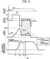
- FIG. 4 is a view showing a relationship between time and a general injection pulse, a driving voltage, a drive current that drive the fuel injection device, a displacement amount of a valve body, and a displacement of a mover.
- FIG. 5 is a view showing details of a drive device for the fuel injection device according to the first embodiment of the present invention.
- the drive circuit 103 When an injection pulse is input to the drive circuit 103, the drive circuit 103 energizes switching elements 505, 506 to apply a high voltage 401 from a high voltage source boosted to a voltage higher than the battery voltage to the solenoid 205, and starts to supply a current to a solenoid 205. When the current value reaches a peak current value I peak preset in the ECU 104, the application of the high voltage 401 is stopped.
- the drive circuit 103 supplies a current to the switching element 506, applies a battery voltage VB by energizing and de-energizing a switching element 507, and provides a switching period for performing control so that the predetermined current 403 is maintained.
- a fuel pressure supplied to the fuel injection device 540 increases, a fluid force acting on the valve body 214 increases, and the time until the valve body 214 reaches a target opening degree increases.
- an arrival timing to the target opening degree may be delayed with respect to an arrival time of the peak current I peak ; however, when the current is rapidly reduced similar to the current 402, the magnetic attraction force acting on the mover 202 rapidly decreases, so that the behavior of the valve body 214 becomes unstable.
- the valve closing may be started regardless of energization.
- the current is gradually decreased by turning ON the switching element 506 during transition of the current 403 from the peak current I peak , it is possible to suppress the decrease in the magnetic attraction force, ensure the stability of the valve body 214 at the high fuel pressure, and suppress the variation in the injection amount.
- the fuel injection device 540 (101 A to 101 D) is driven by such a supply current profile.
- the mover 202 and the valve body 214 start to displace at timing t 41 . Thereafter, the mover 202 and the valve body 214 reach the maximum opening degree.
- the mover 202 collides with the fixed core 207, and the mover 202 performs a bound operation with the fixed core 207. Since the valve body 214 is configured to be displaceable relative to the mover 202, the valve body 214 moves away from the mover 202, and the displacement of the valve body 214 overshoots beyond the maximum opening degree.
- the mover 202 is stationary at a position of a predetermined maximum opening degree.
- the valve body 214 is seated on the mover 202 and is stationary at the position of the maximum opening degree, and is in the valve opening state.
- the displacement amount of the valve body 214 does not become larger than the maximum opening degree.
- the amount of displacement of the mover 202 and the valve body 214 after reaching the maximum opening is equal.
- a CPU 501 is incorporated in the ECU 104, for example.
- the CPU 501 takes in a signal indicating the state of the engine of a pressure sensor 102 attached to the fuel rail 105, an A / F sensor for measuring the amount of air flowing into an engine cylinder, an oxygen sensor for detecting an oxygen concentration of an exhaust gas discharged from the engine cylinder, a crank angle sensor, and the like, and calculates a width Ti (that is, the injection amount) of the injection pulse and the injection timing for controlling the injection amount injected from the fuel injection device 540 (101A to 101D) according to the operating condition of the internal combustion engine.
- the CPU 501 outputs the injection pulse width Ti to a driving IC 502 of the fuel injection device through the communication line 504. Thereafter, the driving IC 502 is switched the energization and de-energization of the switching elements 505, 506, and 507 and supplies the drive current to the fuel injection device 540.
- the switching element 505 is connected between a high voltage source higher than a voltage source VB input to the drive circuit and a high voltage side terminal of the fuel injection device 540.
- the switching elements 505, 506, and 507 are configured by, for example, FETs, transistors, or the like, and can switch between energization and de-energization of the fuel injection device 540.
- a boosted voltage VH which is an initial voltage value of the high voltage source is, for example, 60 V, and is generated by boosting the battery voltage by the boosting circuit 514.
- the boosting circuit 514 includes, for example, a method using a DC/DC converter or the like, and a method using a coil 530, a transistor 531, a diode 532, and a capacitor 533.
- the boosting circuit 514 is configured by the latter method
- the transistor 531 when the transistor 531 is turned ON, the battery voltage VB flows to a ground potential 534 side; however, when the transistor 531 is turned OFF, a high voltage generated in the coil 530 is rectified through the diode 532, and electric charge is accumulated in the capacitor 533.
- This transistor is repeatedly turned ON and OFF until the boosted voltage VH is reached, and the voltage of the capacitor 533 is increased.
- the transistor 531 is connected to the IC 502 or the CPU 501, and the boosted voltage VH output from the boosting circuit 514 is detected by the IC 502 or the CPU 501.
- the boosted voltage VH is input to the IC 502 by a wiring 551, and the boosted voltage VH is detected by the IC 502.
- a diode 535 is provided so that a current flows from the boosting circuit 514 which is a second voltage source toward the solenoid 205 and the contact potential 515.
- a diode 511 is provided so that a current flows from a battery voltage source VB toward the solenoid 205 and the contact potential 515.
- a register and a memory are mounted in order to store numerical data necessary for engine control such as calculation of injection pulse width.
- the register and the memory are included in the drive device 150 or the CPU 501 in the drive device 150.
- the switching element 507 is connected between the low voltage source and the high voltage terminal of the fuel injection device.
- the low voltage source VB is, for example, a battery voltage, and its voltage value is about 12 to 14 V.
- the switching element 506 is connected between the low voltage side terminal of the fuel injection device 540 and the ground potential 515.
- the driving IC 502 detects the current value flowing through the fuel injection device 540 by means of the current detection resistors 508, 512, and 513. On the basis of the detected current value, energization and de-energization of the switching elements 505, 506, 507 is switched to generate a desired drive current.
- Diodes 509 and 510 are provided to apply a reverse voltage to solenoid 205 of the fuel injection device and to rapidly reduce the current being supplied to solenoid 205.
- the CPU 501 communicates with the driving IC 502 through a communication line 503. On the basis of the pressure of the fuel supplied to the fuel injection device 540 and operating conditions, it is possible to switch the drive current generated by the driving IC 502.
- Both ends of the resistors 508, 512, and 513 are connected to the A/D conversion port of the IC 502 by wirings 550, 551, 580, 581, 552, and 553, and are configured so that the voltage applied across the resistors 508, 512, and 513 can be detected by the IC 502.
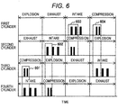
- FIG. 6 is a view showing a relationship of a fuel injection timing of each cylinder in a case where multistage fuel injection is performed three times in an intake stroke and twice in a compression stroke during one combustion cycle including the intake stroke, the compression stroke, an expansion stroke, and an exhaust stroke, for the drive device for the fuel injection device according to the first embodiment.
- FIG. 7 is a view showing a relationship between time and a voltage value of a high voltage source, an injection pulse, a drive current, and a valve body displacement amount in the period of 604 in FIG. 6 , for a first cylinder and a third cylinder.
- FIG. 6 is a view showing a relationship of a fuel injection timing of each cylinder in a case where multistage fuel injection is performed three times in an intake stroke and twice in a compression stroke during one combustion cycle including the intake stroke, the compression stroke, an expansion stroke, and an exhaust stroke, for the drive device for the fuel injection device according to the first embodiment.
- FIG. 7 is a view showing a relationship between time and a voltage value
- FIG. 8 is a view showing a relationship between an injection pulse width and a fuel injection amount and a relationship between an injection pulse width and an injection amount deviation in a case where the voltage value of the high voltage source does not decrease (Q 801 ) and the case where the voltage value of the high voltage source decreases (Q 802 ).
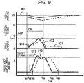
- FIG. 9 is a view showing a relationship between time and a voltage value of a high voltage source, an injection pulse, a drive current, and a valve body displacement amount under a condition that the injection pulse is small (a condition that an injection pulse width Ti is 804 in FIG. 8 ).
- FIG. 9 is a view showing a relationship between time and a voltage value of a high voltage source, an injection pulse, a drive current, and a valve body displacement amount under a condition that the injection pulse is small (a condition that an injection pulse width Ti is 804 in FIG. 8 ).
- FIG. 10 is a view showing a relationship between time and a voltage of a high voltage source, an injection pulse, a drive current, a magnetic attraction force acting on a mover 202, and a valve body displacement amount under a condition that the voltage value of the high voltage source does not decrease and a condition that the voltage decreases.
- FIG. 11 is a view showing a relationship between a boosted voltage and fuel injection timing under three conditions in which fuel pressure supplied to a fuel injection device is different, for the drive device for the fuel injection device according to the first embodiment.
- a method of correcting the injection amount will be described with reference to FIGS 6 , 7 , and 8 .
- a condition under which the injection timing overlaps among the cylinders will be described.
- combustion control is performed to achieve exhaust purification by PN suppression and improvement in fuel efficiency by performing weak stratified combustion.
- the injection timing (injection period) between the cylinders may overlap in some cases.
- FIG. 6 shows, when it is defined as the first, second, third and fourth cylinders from the preceding cylinder, a case of a general in-line four-cylinder engine igniting in order of the first cylinder, the third cylinder, the fourth cylinder, and the second cylinder.
- the injection in the compression stroke in the third cylinder and the injection in the intake stroke in the fourth cylinder overlap.
- the injection in the intake stroke in the second cylinder and the injection in the compression stroke in the fourth cylinder overlap.
- the injection in the intake stroke in the first cylinder and the injection in the compression stroke in the second cylinder overlap.
- the injection in the compression stroke in the first cylinder and the injection in the intake stroke in the third cylinder overlap In the period of 601, the injection in the compression stroke in the first cylinder and the injection in the intake stroke in the third cylinder overlap.
- boosting circuit 514 is provided for each of the odd-numbered cylinders 1, 3 and the even-numbered cylinders 2, 4, or one boosting circuit 514 is shared by the four cylinders.
- the number of switching elements including a transistor or the like securing withstand voltage and the number of capacitors capable of storing high voltage can be reduced, thereby reducing the cost of the drive circuit 103.
- the switching element 531 in order to store the electric charge in the capacitor 533, the switching element 531 is controlled to repeat ON/OFF at high frequency.
- the boosting circuit 514 generates heat, so that the time of applying a high voltage to the solenoid 202 or the current value that can be passed through the solenoid 202 may be restricted.
- heat generation of the drive circuit 103 can be suppressed.
- FIG. 7 shows, as an example, a condition (case) in which multistage injection is performed with a configuration in which one boosting circuit 514 is provided for each of the first and third odd-numbered cylinders and the second and fourth even-numbered cylinders.
- FIG. 7 shows the first and third odd-number cylinders, the second and fourth even-numbered cylinders are also the same as in FIG. 7 .
- the drive current of the preceding cylinder (first cylinder) and the valve body displacement amount in the case where the timing when the injection pulse is turned ON is matched with the timing when the injection pulse of the third cylinder is turned ON are indicated by broken lines 712 and 713.
- the voltage value of the high voltage source (boosting circuit) 514 is controlled to be the boosted voltage VH.
- a voltage is applied to the solenoid 205 from the high voltage source 514, and the electric charge stored in the capacitor 533 decreases, so that the voltage value of the high voltage source 514 decreases.
- the application of the voltage from the high voltage source 514 to the solenoid 205 is stopped and the battery voltage source VB or 0 V is applied to the solenoid 205.
- the voltage value of the high voltage source 514 After a timing t 72 , the voltage value of the high voltage source 514 returns toward the boosted voltage VH; however, before returning to the boosted voltage VH, the injection pulse in the compression stroke in the first cylinder is energized at timing t 73 , and the voltage value of the high voltage source 514 decreases. Thereafter, when the timing reaches the timing t 74 at which the current value of the first cylinder becomes the peak current I peak , the voltage application from the high voltage source 514 to the solenoid 205 is stopped; therefore, the current value returns to the boosted voltage value VH after a certain period of time has elapsed.
- a valve opening delay time of the first cylinder until the valve body 214 reaches the target opening degree after the injection pulse is turned ON becomes longer, and the injection amount decreases.
- the injection pulse width is corrected so as to be longer than the injection pulse width in the case where the voltage does not decrease, so that the injection amount is increased. This makes it possible to suppress variation in the injection amount between the cylinders between the first cylinder and the third cylinder.
- the pulse width of the injection pulse to the energization time (for example, the injection pulse width 815 in FIG. 8 ) that is closed after the drive current is switched to the holding current
- the pulse width of the injection pulse in the case where the fuel injection timing or the fuel injection period overlaps between the cylinders is corrected so as to be longer than the pulse width of the injection pulse in the case where the injection timing or the injection period does not overlap.
- the pulse width of the injection pulse in the case where the voltage of the high voltage source 514 decreases is corrected so as to be longer than the pulse width of the injection pulse in the case where the voltage of the high voltage source does not decrease.
- the amount of decrease in the injection amount depends on the voltage value of the high voltage source 514, it is preferable to determine the correction amount of the injection pulse according to the voltage value of the high voltage source 514. Further, by connecting a contact 516 to the IC 502 or an A/D conversion port of the CPU 501, voltage detection means for detecting the voltage value of the high voltage source, which is the output of the boosting circuit 514, may be provided. In the present embodiment, the contact 516 is connected to the A / D conversion port of the IC 502 via the wiring 551.
- the relationship between the injection amount, the voltage value of the high voltage source 514, and the injection pulse width is preferably given to the CPU 501 in advance. With such a configuration, it is possible to determine an appropriate injection pulse width Ti from the required injection amount calculated by the CPU 501 and the detected voltage value of the high voltage source 514.
- FIG. 7 shows a case where the pulse width Ti of the injection pulse is sufficiently long. This corresponds to the case where the injection pulse width Ti shown in FIG. 8 is longer than the pulse width at 814, and corresponds to a section indicated by the injection amount characteristic 830.
- the valve body 214 separates from the valve seat 218 and starts to displace; however, since the valve closing starts before the valve body 214 reaches the target opening degree, the injection amount decreases with respect to a one-dot chain line 820 extrapolated from a linear region 830 in which the relationship between the injection pulse width and the injection amount becomes linear.
- valve closing starts immediately after reaching the target opening degree, and the locus of the valve body 214 becomes parabolic motion.
- the kinetic energy of the valve body 214 in the valve opening direction is large and the magnetic attraction force acting on the mover 202 is large, so that the proportion of the time required for closing the valve body 214 increases, so that the injection amount increases with respect to the one-dot chain line 820.
- the valve body 214 starts to close at the timing when the bound amount of the valve body 214 caused by collision of the mover 202 with the fixed core 207 at the timing when the valve body 214 reaches the target opening degree is the maximum. Therefore, a repulsive force when the mover 202 and the fixed core 207 collide with each other acts on the mover 202, the valve closing delay time from when the injection pulse is turned OFF until when the valve body 214 closes becomes small. As a result, the injection amount decreases with respect to the one-dot chain line 820.
- the valve closing delay time becomes longer, and the injection amount increases with respect to the one-dot chain line 820.
- the valve opening delay time increases due to the kinetic energy of the mover 202. Therefore, even after the current supplied to the solenoid 205 reaches the holding current, the injection amount at the point 804 may become larger than the one-dot chain line 820 in some cases.
- the fuel injection amount linearly increases in accordance with the increase in the injection pulse width Ti.
- the injection pulse width is smaller than the linear region 830
- the injection amount becomes larger in the case where the voltage is lower than when the voltage of the high voltage source 514 does not decrease.
- the displacement amount of the valve body 214 until the valve body 214 reaches the target opening degree is equivalent to the point 805.
- the valve closing delay time is the same between the condition where the voltage of the high voltage source 514 does not decrease and the condition where the voltage of the high voltage source 514 decreases, the injection amount becomes smaller in the case where the voltage of the high voltage source 514 is lower than when where the voltage does not decrease.
- the injection amount is determined by the area of the displacement amount of the valve body 214; therefore, in the case where the voltage of the high voltage source 514 is lower than when it is not decreased, the injection amount increases.
- a drive current when the voltage value of the high voltage source 514 does not decrease is indicated by 910
- a displacement amount of the valve body is indicated by 911
- a drive current when the voltage of the high voltage source 514 decreases is indicated by 912
- a valve body displacement amount is indicated by 913.
- FIG. 7 the case where the pulse width Ti of the injection pulse is shorter than that in the case of FIG. 7 is shown. This corresponds to the case where the injection pulse width Ti shown in FIG. 8 is the pulse width at 813.
- a waveform denoted by reference numeral 921 in FIG. 9 is a holding current supplied from the battery power source VB when the injection pulse width Ti is assumed to be the same length as in FIG. 7 .
- the time it takes for the drive current to reach the peak current value I peak is delayed when the voltage of the high voltage source 514 is lower than when the voltage of the high voltage source 514 does not decrease.
- the drive current value at a timing t 94 at which the injection pulse is turned OFF increases.
- the magnetic attraction force increases and the valve closing delay time increases.
- the second reason for the increase in the injection amount is the bound of the valve body 214 that occurs after the mover 202 reaches the target opening degree.
- the valve body 214 starts to close from the target opening degree.
- the bound that occurs after the valve body 214 reaches the target opening degree does not converge and the valve closing operation is started while the mover 202 is moving in the direction of the target opening degree. Therefore, the valve closing delay time increases due to the kinetic energy of the mover 202.
- the injection amount is determined by a tradeoff between the valve opening delay time and the valve closing delay time.
- the injection amount until the injection pulse is turned OFF becomes small and the injection amount from the turning off of the injection pulse to the completion of closing of the valve body 214 becomes large.
- the injection pulse width 815 as compared with the injection pulse width 815 of a linear region (linear region) 830, there is a case that the injection amount becomes larger in the case where the deviation of the injection amount changes in a positive direction or the voltage is lower than when the voltage of the high voltage source 514 does not decrease.
- the injection pulse width 804 in FIG. 830 in the case where the voltage of the high voltage source 514 is lower than when the voltage of the high voltage source 514 does not decrease, it is preferable to correct so that the injection pulse width becomes long. Thus, it is possible to suppress the change in the injection amount caused by the valve opening delay. Such a correction of the injection pulse width is preferably performed by the drive device 150. On the other hand, in the case of setting the pulse width of the injection pulse to the energization time (the injection pulse width 804 in FIG.
- the pulse width of the injection pulse in the case where the voltage of the high voltage source 514 decreases may be corrected so as to be shorter than the pulse width of the injection pulse in the case where the voltage of the high voltage source does not decrease.
- the amount of change in the injection amount due to the decrease in the voltage of the high voltage source 514 depends on the voltage value of the high voltage source 514. Therefore, the contact 516 is connected to the IC 502 or the A/D conversion port of the CPU 501 so that the voltage value of the high voltage source 514 which is the output of the boosting circuit 514 can be detected, the relationship between the injection amount, the voltage value of the high voltage source 514, and the injection pulse width is preferably given to the CPU 501 in advance. With such a configuration, it is possible to determine an appropriate injection pulse width Ti from the required injection amount calculated by the CPU 501 and the detected voltage value of the high voltage source 514.
- the injection amount for the injection pulse width Ti from 813 to 814 under a condition that the voltage value of the high voltage source 514 decreases also depends on the current value at the timing at which the injection pulse is turned OFF. Both ends of the resistor 508 or the resistor 513 are connected to the A/D conversion port of the CPU 501 or the IC 502, and current detection means for detecting the current value after the drive current reaches the peak current I peak may be provided. With this configuration, a current is detected immediately before the timing when the injection pulse is stopped, and the current value at timing when the injection pulse is turned OFF can be estimated from the current value.
- the injection pulse width in the next injection may be corrected so that the injection amount for the amount of change in the injection amount in the previous injection under a condition of the next multistage injection in one combustion cycle is corrected.
- the total amount of the injection amount during one combustion cycle in the case of performing the multistage injection can be matched between cylinders and for each cycle. Therefore, it is possible to suppress an increase in PN caused by the deviation of the injection amount from the required value.
- the relationship between the injection amount, the voltage value of the high voltage source 514, the drive current value, and the injection pulse width Ti may be previously given to the CPU 501 or the IC 502 as MAP information or approximate expression.
- the correction amount of the injection pulse is calculated from the estimated current value, and the injection pulse width necessary for achieving the required injection amount can be appropriately determined.
- the current value at the timing when the injection pulse is turned OFF is influenced by the voltage value of the high voltage source 514 and the resistance value of the solenoid 205.
- the resistance value of the solenoid 205 increases as the solenoid 205 generates heat.
- the drive cycle of the fuel injection device 540 contributing to the heat generation of the solenoid 205, and the like are equal. Therefore, if the voltage value of the high voltage source 514 can be detected, the current value at the timing when the injection pulse is turned OFF can be estimated. Therefore, the voltage value of the high voltage source 514 may be detected immediately before the fuel injection timing, and the correction amount of the injection pulse width may be determined from the detected value.
- the time resolution of the A/D conversion port is restricted due to limitations of hardware.
- the injection amount deviation is indicated by the ratio of the injection amount Q 802 in the case where the voltage with respect to the injection amount Q 801 in the case where the voltage of the high voltage source 514 does not decrease decreases. Therefore, an injection amount deviation 860 is larger than the injection amount deviation 840. However, in the region where the injection amount deviation 840 occurs, since the injection amount Q 801 is larger than the injection amount Q 802 , the absolute value of the correction amount of the injection pulse width necessary for correcting the injection amount deviation 860 becomes smaller than the absolute value of the correction amount of the injection pulse width necessary for correcting the injection amount deviation 840.
- the absolute value of the correction amount of the injection pulse width necessary for correcting the injection amount deviation 860 in the injection pulse width 813 and further correcting the injection amount so as to match the one-dot chain line 820 extrapolated from the linear region 830 is smaller than the absolute value of the correction amount of the injection pulse width necessary for correcting the injection amount deviation 840 (the correction amount of the injection pulse width necessary for matching the injection amount Q 801 ).
- the injection pulse width is smaller than the injection pulse width 814 as compared with the region in which the injection pulse width is larger than the injection pulse width 814, it is preferable to correct so that the absolute value of the correction amount of the injection pulse width in the case where the voltage of the high voltage source 514 decreases becomes small.
- the absolute value of the correction amount of the pulse width of the injection pulse is lower than when the pulse width of the injection pulse is set to the energization time at which the valve body is closed after the drive current is switched to the holding current (for example, the injection pulse width 815 in FIG. 8 )
- fuel injection may be performed under a condition that the voltage of the high voltage source 514 decreases.
- the boosting circuit 514 is configured for each cylinder, fuel injection is performed under a condition that the voltage of the high voltage source 514 decreases; therefore, variation in the injection amount occurs in the first injection and the second injection during the corresponding stroke. Even in such a case, it is possible to suppress variation in the injection amount by correcting the injection pulse width described in FIGS. 6 , 7 , 8 , and 9 .
- valve body displacement amount shown in FIG. 10 the valve body displacement amount in the case where the voltage value of the high voltage source 514 at the timing when the injection pulse is turned ON becomes a boosted voltage VH that is an initial value and under a condition that the fuel pressure is small is indicated by 1001, and the valve body displacement amount under a condition that the fuel pressure is high is indicated by 1003. Furthermore, in FIG. 10
- valve body displacement amount in the case where the voltage value of the high voltage source 514 at the timing when the injection pulse is turned ON is lower than the initial value and under a condition that the fuel pressure is small is shown at 1002
- valve body displacement amount under a condition that the fuel pressure is high is shown at 1004.
- fuel pressures are 1101, 1102, and 1103 in descending order.
- the valve opening start timing of the valve body 214 is delayed, and the fuel injection timing is delayed.
- the injection timing of fuel is delayed under the condition of fuel injection in the compression stroke, the fuel spray easily adheres to the piston, and the formation state of the fuel spray is changed, so that the homogeneity of the spray decreases. Attachment of the fuel spray to the piston and decrease in homogeneity of the spray can lead to an increase in PN.
- the fuel injection timing is delayed, so that the timing of fuel injection is delayed with respect to the opening/closing timing of the intake valve.
- the homogeneity of the air-fuel mixture of the air flowing into the piston cylinder and the injected fuel varies for each cylinder or for each injection of multistage injection, so that the PN may increase.
- the voltage value of the high voltage source 514 or the current flowing through the solenoid 205 is detected by the CPU 502 or the IC 501, and the amount of decrease from the voltage value of the high voltage source 514 or the boosted voltage VH is calculated from the detected value to correct the energization timing of the injection pulse.
- the relationship between the voltage value of the high voltage source 514 and the fuel injection timing is substantially linear.
- the relationship between the voltage value of the high voltage source 514 and the injection timing is preferably given to the CPU 501 in advance.
- valve body 214 starts valve opening at the timing when the magnetic attraction force acting on the mover 102 exceeds the force in the valve closing direction acting on the valve body 214 and the mover 102.
- the resistance value R so of the solenoid 205 varies with the heat generation of the solenoid 205, by detecting the current Iso, the calculation accuracy of the correction value of the energization timing can be improved, as compared with the case where the energization timing is corrected only with the voltage value V Hi of the high voltage source. As a result, the correction accuracy of the valve opening start timing of the valve body 214 can be enhanced, and the effect of suppressing PN is enhanced.
- the correction of energization timing by the current value it is preferable to detect the current value before the valve body 214 starts to open after the start of energization to the solenoid 205, and to determine the correction amount of energization timing according to the detected current value.
- the detection of the current value it is preferable to use the energization timing as a trigger.
- the current value Iso during the period from the start of the energization to the solenoid 205 until the valve body 214 opens is detected at two or more points, and the correction amount of energization timing may be determined using the inclination of the current value Iso, that is, time differentiation or an approximate expression.
- the influence of the detection error of the current Iso can be reduced as compared with the case of detecting one point of the current value Iso, so that it is possible to improve the correction accuracy of the valve opening start timing.
- the relationship between the voltage value and the drive current of the high voltage source 514 and the correction amount of the energization timing of the injection pulse may be previously given to the CPU 501 as MAP data or an approximate expression.
- the energization timing can be appropriately determined from the current value detected by such a configuration and the voltage value of the high voltage source 514, and variation in the injection timing can be suppressed.
- the delay in the energization timing of the injection pulse when the voltage value of the high voltage source 514 decreases is influenced by the fuel pressure supplied to the fuel injection device 540.
- the sensitivity of the change in the fuel injection timing due to the decrease in the voltage value of the high voltage source 514 is different.
- the higher the fuel pressure the larger the inclination of the fuel injection timing with respect to the voltage value of the high voltage source 514.
- the force in the valve closing direction acting on the valve body 214 when the fuel pressure is small is indicated by 1007
- the force in the valve closing direction acting on the valve body 214 when the fuel pressure is high is indicated by 1006.
- the resultant force of the fluid force obtained by multiplying the cross sectional area of the diameter of the valve body 214 and the valve seat 218 by the fuel pressure and the spring load 210 acts as the force in the valve closing direction.
- a drive current is supplied to the solenoid 205, and a magnetic attraction force acts on the mover 202 with a time delay due to the influence of the eddy current.
- the valve body 214 starts to open after the timing t 102 at which the magnetic attraction force exceeds the force 1007 in the valve closing direction.
- the valve body 214 starts to open after the timing t 103 as indicated by 1002.
- valve opening start timing difference 1011 is larger than the valve opening start timing difference 1010.
- the magnetic attraction force acting on the mover 202 depends on the energy of the drive current, that is, the time integral value of the drive current.
- the inclination of the drive current decreases and the inclination of the magnetic attraction force also decreases.
- the delay of the valve opening start timing and the injection timing in the case where the voltage of the high voltage source 514 decreases is larger in 1006 where the fuel pressure is higher. Therefore, by detecting the fuel pressure supplied to the fuel injection device 540 detected, and determining the energization timing for correcting the injection timing according to the fuel pressure and the voltage value of the high voltage source 514, it is possible to suppress variations in the injection timing.
- the pressure signal detection means for detecting the fuel pressure.
- the detection of the fuel pressure may be carried out by detecting the fuel pressure at timing before the trigger, with the energization timing of the injection pulse calculated by the CPU 501 as a trigger.
- the pressure in a rail piping 133 fluctuates, and the pressure detected by disconnecting the pressure sensor 102 also varies.
- FIG. 12 is a view showing, in a case where a voltage value of a high voltage source does not decrease and a case where the voltage value decreases, a drive current and a valve body displacement amount at an injection pulse width at a point 815 in FIG. 8 , and a drive current and a valve body displacement amount at an injection pulse width at a point 802, for a drive device for a fuel injection device according to a second embodiment.
- a drive current waveform in the case where the voltage of the high voltage source 514 does not decrease compared with the initial value (boosted voltage VH) is indicated by 1201
- a valve body displacement amount is indicated by 1202
- a current waveform when the voltage of the high voltage source 514 decreases compared with the initial value is indicated by 1203, and a valve body displacement amount is indicated by 1204.
- a current waveform in the case where the voltage of the high voltage source 514 does not decrease compared with the initial value is indicated by 1205
- a displacement amount of the valve body is indicated by 1206
- a current waveform when the voltage of the high voltage source 514 decreases compared with the initial value is indicated by 1207
- a valve body displacement amount is indicated by 1208.
- valve closing starts immediately before reaching the target opening degree, and the locus of the valve body 214 becomes parabolic motion.
- the valve body 214 is driven under the condition of the half lift in which the valve body 214 is closed without reaching the target opening degree.
- the valve body displacement amount increases along with the valve closing delay time according to the injection pulse as compared with a condition that the energization is stopped after the valve body 214 reaches the target opening degree; therefore, the sensitivity of the injection pulse width to the injection amount is high.
- the drive current value at the timing of stopping energization is lower than when the voltage does not decrease. Furthermore, when the voltage of the high voltage source 514 decreases from the initial boosted voltage VH, the kinetic energy of the valve body 214 and the mover 202 is small at the timing of stopping energization as the valve opening start timing is delayed, as compared with the case where the valve body 214 and the mover 202 do not decrease. From these facts, the maximum value 1210 of the displacement amount of the valve body 214 becomes small.
- the present invention is not limited to the embodiments described above, but includes various modified examples.
- the above-described embodiments have been described in detail in order to explain the present invention in an easy-to-understand manner, and are not necessarily limited to those having all the configurations.
- a drive device for a fuel injection device is configured to open a valve body of an electromagnetic fuel injection device by energizing a solenoid to apply a magnetic attraction force between a fixed core and a mover, the drive device comprising a function of applying a high voltage to the solenoid when the valve body opens, and after the drive current flowing through the solenoid reaches a predetermined current value, switching the drive current to a holding current smaller than the predetermined current value to maintain a valve open state, the drive device of the fuel injection device being configured to generate an injection pulse and control a time for energizing the solenoid with a pulse width of the injection pulse, the drive device comprising a function of, when the pulse width of the injection pulse is set to an energization time at which the valve body is closed after the drive current is switched to the holding current, correcting the pulse width of the injection pulse in a case where the fuel injection timing or the fuel injection period overlaps between the cylinders so as to be longer than the pulse
- the drive device for the fuel injection device comprises:
- the drive device for the fuel injection device comprises:
- the drive device for the fuel injection device according to the third aspect wherein a fuel injection during one combustion stroke is performed while being divided into a plurality of times.
- the drive device for the fuel injection device according to the fourth aspect, wherein a correction amount of the injection pulse is calculated according to a voltage value of the second voltage source.
- the drive device for the fuel injection device comprises a function of, when a fuel injection is performed under a condition that the voltage value of the second voltage source decreases, performing correction to advance an application timing of the injection pulse as compared with the case where the voltage of the second voltage source does not decrease.
- the drive device for the fuel injection device comprises a function of acquiring a signal from a pressure sensor that detects a fuel pressure and correcting the application timing of the injection pulse earlier as a pressure acquired from the pressure sensor is larger.
Landscapes
- Engineering & Computer Science (AREA)
- Chemical & Material Sciences (AREA)
- Combustion & Propulsion (AREA)
- Mechanical Engineering (AREA)
- General Engineering & Computer Science (AREA)
- Physics & Mathematics (AREA)
- Electromagnetism (AREA)
- Electrical Control Of Air Or Fuel Supplied To Internal-Combustion Engine (AREA)
- Fuel-Injection Apparatus (AREA)
- Combined Controls Of Internal Combustion Engines (AREA)
Applications Claiming Priority (3)
| Application Number | Priority Date | Filing Date | Title |
|---|---|---|---|
| JP2014234099 | 2014-11-19 | ||
| PCT/JP2015/076600 WO2016080067A1 (fr) | 2014-11-19 | 2015-09-18 | Dispositif de commande pour dispositif d'injection de carburant |
| EP15861043.6A EP3222840B1 (fr) | 2014-11-19 | 2015-09-18 | Dispositif de commande pour dispositif d'injection de carburant |
Related Parent Applications (1)
| Application Number | Title | Priority Date | Filing Date |
|---|---|---|---|
| EP15861043.6A Division EP3222840B1 (fr) | 2014-11-19 | 2015-09-18 | Dispositif de commande pour dispositif d'injection de carburant |
Publications (1)
| Publication Number | Publication Date |
|---|---|
| EP3670880A1 true EP3670880A1 (fr) | 2020-06-24 |
Family
ID=56013627
Family Applications (2)
| Application Number | Title | Priority Date | Filing Date |
|---|---|---|---|
| EP15861043.6A Active EP3222840B1 (fr) | 2014-11-19 | 2015-09-18 | Dispositif de commande pour dispositif d'injection de carburant |
| EP19192807.6A Pending EP3670880A1 (fr) | 2014-11-19 | 2015-09-18 | Dispositif d'entraînement pour dispositif d'injection de carburant |
Family Applications Before (1)
| Application Number | Title | Priority Date | Filing Date |
|---|---|---|---|
| EP15861043.6A Active EP3222840B1 (fr) | 2014-11-19 | 2015-09-18 | Dispositif de commande pour dispositif d'injection de carburant |
Country Status (5)
| Country | Link |
|---|---|
| US (2) | US10161339B2 (fr) |
| EP (2) | EP3222840B1 (fr) |
| JP (3) | JP6254298B2 (fr) |
| CN (1) | CN107110053B (fr) |
| WO (1) | WO2016080067A1 (fr) |
Families Citing this family (24)
| Publication number | Priority date | Publication date | Assignee | Title |
|---|---|---|---|---|
| US9926874B2 (en) * | 2013-07-29 | 2018-03-27 | Hitachi Automotive Systems, Ltd. | Drive device for fuel injection device, and fuel injection system |
| JP6229598B2 (ja) * | 2014-06-11 | 2017-11-15 | トヨタ自動車株式会社 | 内燃機関の制御装置 |
| JP6723115B2 (ja) * | 2016-08-31 | 2020-07-15 | 日立オートモティブシステムズ株式会社 | 燃料噴射装置の制御装置 |
| JP6856387B2 (ja) | 2017-01-20 | 2021-04-07 | 日立Astemo株式会社 | 燃料噴射装置の駆動装置 |
| DE102017208273A1 (de) * | 2017-05-17 | 2018-11-22 | Robert Bosch Gmbh | Verfahren zum Umschalten eines Magnetventils |
| US10443533B2 (en) * | 2017-10-23 | 2019-10-15 | GM Global Technology Operations LLC | Mild hybrid powertrain with simplified fuel injector boost |
| JP7035466B2 (ja) * | 2017-11-10 | 2022-03-15 | 株式会社デンソー | 燃料噴射制御装置 |
| JP6957113B2 (ja) * | 2018-01-30 | 2021-11-02 | 住友重機械工業株式会社 | レーザ制御装置 |
| DE112019002301T5 (de) * | 2018-07-20 | 2021-02-18 | Hitachi Automotive Systems, Ltd. | Kraftstoffeinspritzungs-Steuervorrichtung |
| JP7143715B2 (ja) * | 2018-10-05 | 2022-09-29 | 株式会社デンソー | 燃料噴射弁およびエンジンシステム |
| WO2020110555A1 (fr) * | 2018-11-29 | 2020-06-04 | 日立オートモティブシステムズ株式会社 | Dispositif de commande pour moteur à combustion interne |
| CN110107726B (zh) * | 2019-05-08 | 2020-05-22 | 合肥工业大学 | 一种减少开关电磁阀关闭时延的控制方法 |
| JP7259640B2 (ja) * | 2019-08-22 | 2023-04-18 | 株式会社デンソー | 電磁弁制御装置 |
| US11230990B2 (en) * | 2019-11-11 | 2022-01-25 | Caterpillar Inc. | Method and system for valve movement detection |
| US11873775B2 (en) * | 2019-11-21 | 2024-01-16 | Hitachi Astemo, Ltd. | Fuel injection control device |
| JP7367614B2 (ja) * | 2020-05-28 | 2023-10-24 | 株式会社デンソー | 噴射制御装置 |
| JP7322816B2 (ja) * | 2020-05-28 | 2023-08-08 | 株式会社デンソー | 噴射制御装置 |
| JP7354940B2 (ja) * | 2020-06-29 | 2023-10-03 | 株式会社デンソー | 噴射制御装置 |
| RU2756292C1 (ru) * | 2020-08-24 | 2021-09-29 | Акционерное общество "Корпорация "Московский институт теплотехники" (АО "Корпорация "МИТ") | Способ управления электромагнитным клапаном и устройство для его осуществления |
| DE102020127539A1 (de) * | 2020-10-20 | 2022-04-21 | Faurecia Autositze Gmbh | Verfahren zur Ansteuerung eines Fahrzeugsitz-Ventils |
| US11220975B1 (en) * | 2021-03-17 | 2022-01-11 | Ford Global Technologies, Llc | Methods and systems for compensating for fuel injector closing time |
| US11698036B2 (en) * | 2021-07-28 | 2023-07-11 | Ford Global Technologies, Llc | Method and system for operating a refueling valve |
| US11795886B2 (en) | 2021-12-13 | 2023-10-24 | Caterpillar Inc. | Reduced energy waveform for energizing solenoid actuator in fuel injector valve |
| DE102022211461A1 (de) | 2022-10-28 | 2024-05-08 | Robert Bosch Gesellschaft mit beschränkter Haftung | Verfahren zur Prädiktion einer Ausgangsspannung an einem Gleichspannungswandler, Kraftstoffeinspritzsystem, Recheneinheit und Computerprogramm |
Citations (5)
| Publication number | Priority date | Publication date | Assignee | Title |
|---|---|---|---|---|
| JP2005171928A (ja) | 2003-12-12 | 2005-06-30 | Denso Corp | アクチュエータ駆動装置および燃料噴射装置 |
| US6923161B2 (en) * | 2002-03-28 | 2005-08-02 | Siemens Vdo Automotive Corporation | Fuel injection timer and current regulator |
| JP2011052631A (ja) | 2009-09-03 | 2011-03-17 | Denso Corp | 燃料噴射制御装置 |
| WO2014181166A2 (fr) * | 2013-05-10 | 2014-11-13 | Toyota Jidosha Kabushiki Kaisha | Appareil de commande pour soupape d'injection de carburant et procédé associé |
| EP3029309A1 (fr) * | 2013-07-29 | 2016-06-08 | Hitachi Automotive Systems, Ltd. | Dispositif de commande pour dispositif d'injecteur de carburant, et système d'injection de carburant |
Family Cites Families (27)
| Publication number | Priority date | Publication date | Assignee | Title |
|---|---|---|---|---|
| US5245261A (en) * | 1991-10-24 | 1993-09-14 | International Business Machines Corporation | Temperature compensated overcurrent and undercurrent detector |
| JPH07224708A (ja) * | 1994-02-10 | 1995-08-22 | Nippondenso Co Ltd | 内燃機関の燃料噴射制御装置 |
| EP0805999B1 (fr) * | 1995-01-27 | 1999-03-17 | Poul Johansen Development A/S | Transporteurs vibrants |
| US6208497B1 (en) * | 1997-06-26 | 2001-03-27 | Venture Scientifics, Llc | System and method for servo control of nonlinear electromagnetic actuators |
| US6942469B2 (en) * | 1997-06-26 | 2005-09-13 | Crystal Investments, Inc. | Solenoid cassette pump with servo controlled volume detection |
| DE10064505A1 (de) * | 2000-12-22 | 2002-07-04 | Bosch Gmbh Robert | Verfahren und Vorrichtung zur Überwachung eines Abstands zwischen zwei Einspritzvorgängen |
| JP3876788B2 (ja) | 2002-08-01 | 2007-02-07 | マツダ株式会社 | エンジンの燃料噴射制御装置 |
| JP2004251183A (ja) * | 2003-02-19 | 2004-09-09 | Toyota Motor Corp | 内燃機関の制御装置 |
| JP4032356B2 (ja) | 2004-04-14 | 2008-01-16 | 株式会社デンソー | 燃料噴射装置 |
| JP4396510B2 (ja) * | 2004-12-17 | 2010-01-13 | トヨタ自動車株式会社 | 内燃機関の制御装置 |
| JP2008190388A (ja) * | 2007-02-02 | 2008-08-21 | Denso Corp | 電磁弁駆動装置及び燃料噴射制御装置 |
| JP5327124B2 (ja) | 2010-04-09 | 2013-10-30 | 株式会社デンソー | 燃料噴射制御装置 |
| JP5519410B2 (ja) * | 2010-06-01 | 2014-06-11 | 本田技研工業株式会社 | 内燃機関の燃料供給装置 |
| JP5698938B2 (ja) * | 2010-08-31 | 2015-04-08 | 日立オートモティブシステムズ株式会社 | 燃料噴射装置の駆動装置及び燃料噴射システム |
| JP5772025B2 (ja) * | 2011-02-07 | 2015-09-02 | 日産自動車株式会社 | 内燃機関の制御装置 |
| JP2013007375A (ja) * | 2011-05-24 | 2013-01-10 | Nissan Motor Co Ltd | 内燃機関の燃料噴射制御装置 |
| GB201207289D0 (en) * | 2011-06-14 | 2012-06-06 | Sentec Ltd | Flux switch actuator |
| JP5838074B2 (ja) * | 2011-11-08 | 2015-12-24 | 日立オートモティブシステムズ株式会社 | 内燃機関の燃料噴射制御装置 |
| JP5754357B2 (ja) * | 2011-11-18 | 2015-07-29 | 株式会社デンソー | 内燃機関の燃料噴射制御装置 |
| JP5542884B2 (ja) * | 2012-08-30 | 2014-07-09 | 三菱電機株式会社 | 車載エンジン制御装置 |
| DE102012217121B4 (de) * | 2012-09-24 | 2022-02-03 | Vitesco Technologies GmbH | Elektrische Ansteuerung eines Ventils basierend auf Kenntnis des Schließzeitpunkts bzw. Öffnungszeitpunktes des Ventils |
| JP5462387B1 (ja) * | 2013-04-18 | 2014-04-02 | 三菱電機株式会社 | 車載エンジン制御装置及びその制御方法 |
| JP5831502B2 (ja) * | 2013-06-07 | 2015-12-09 | トヨタ自動車株式会社 | 燃料噴射弁の制御装置 |
| WO2015071686A1 (fr) * | 2013-11-15 | 2015-05-21 | Sentec Ltd | Unité de commande pour un injecteur de carburant |
| JP6307971B2 (ja) * | 2014-03-27 | 2018-04-11 | 株式会社デンソー | 燃料噴射制御装置 |
| JP6358163B2 (ja) * | 2015-04-24 | 2018-07-18 | 株式会社デンソー | 内燃機関の燃料噴射制御装置 |
| JP2017106354A (ja) * | 2015-12-08 | 2017-06-15 | 株式会社デンソー | 制御装置 |
-
2015
- 2015-09-18 CN CN201580059022.8A patent/CN107110053B/zh active Active
- 2015-09-18 US US15/527,060 patent/US10161339B2/en active Active
- 2015-09-18 EP EP15861043.6A patent/EP3222840B1/fr active Active
- 2015-09-18 EP EP19192807.6A patent/EP3670880A1/fr active Pending
- 2015-09-18 WO PCT/JP2015/076600 patent/WO2016080067A1/fr active Application Filing
- 2015-09-18 JP JP2016560096A patent/JP6254298B2/ja active Active
-
2017
- 2017-11-29 JP JP2017228764A patent/JP6462835B2/ja active Active
-
2018
- 2018-11-20 US US16/197,152 patent/US10634083B2/en active Active
- 2018-12-27 JP JP2018244961A patent/JP6677792B2/ja active Active
Patent Citations (5)
| Publication number | Priority date | Publication date | Assignee | Title |
|---|---|---|---|---|
| US6923161B2 (en) * | 2002-03-28 | 2005-08-02 | Siemens Vdo Automotive Corporation | Fuel injection timer and current regulator |
| JP2005171928A (ja) | 2003-12-12 | 2005-06-30 | Denso Corp | アクチュエータ駆動装置および燃料噴射装置 |
| JP2011052631A (ja) | 2009-09-03 | 2011-03-17 | Denso Corp | 燃料噴射制御装置 |
| WO2014181166A2 (fr) * | 2013-05-10 | 2014-11-13 | Toyota Jidosha Kabushiki Kaisha | Appareil de commande pour soupape d'injection de carburant et procédé associé |
| EP3029309A1 (fr) * | 2013-07-29 | 2016-06-08 | Hitachi Automotive Systems, Ltd. | Dispositif de commande pour dispositif d'injecteur de carburant, et système d'injection de carburant |
Also Published As
| Publication number | Publication date |
|---|---|
| JPWO2016080067A1 (ja) | 2017-07-20 |
| EP3222840B1 (fr) | 2019-09-11 |
| JP2018059511A (ja) | 2018-04-12 |
| CN107110053B (zh) | 2020-06-19 |
| US10634083B2 (en) | 2020-04-28 |
| CN107110053A (zh) | 2017-08-29 |
| EP3222840A1 (fr) | 2017-09-27 |
| US20190085783A1 (en) | 2019-03-21 |
| JP2019056378A (ja) | 2019-04-11 |
| US10161339B2 (en) | 2018-12-25 |
| US20180283306A1 (en) | 2018-10-04 |
| JP6677792B2 (ja) | 2020-04-08 |
| JP6462835B2 (ja) | 2019-01-30 |
| WO2016080067A1 (fr) | 2016-05-26 |
| EP3222840A4 (fr) | 2018-07-04 |
| JP6254298B2 (ja) | 2017-12-27 |
Similar Documents
| Publication | Publication Date | Title |
|---|---|---|
| US10634083B2 (en) | Drive device for fuel injection device | |
| US10823104B2 (en) | Drive device for fuel injection devices | |
| JP6400825B2 (ja) | 燃料噴射装置の駆動装置 | |
| US10677184B2 (en) | Drive device for fuel injection device | |
| US9347393B2 (en) | Fuel injection device | |
| US11098670B2 (en) | Drive device for fuel injection device | |
| US10883434B2 (en) | Control device for fuel injection device | |
| JP6457908B2 (ja) | 制御装置及び燃料噴射システム | |
| JP6524206B2 (ja) | 燃料噴射装置、燃料噴射装置の制御装置、燃料噴射装置の制御方法、燃料噴射システム | |
| WO2020195206A1 (fr) | Dispositif de commande pour dispositif d'injection de carburant | |
| JP7177458B2 (ja) | 燃料噴射装置を制御する制御装置 | |
| JP6670893B2 (ja) | 燃料噴射装置の駆動装置 | |
| US20210388790A1 (en) | Control Device for Vehicle Fuel Injection Control Method for Vehicle and Fuel Injection Control Program for Vehicle |
Legal Events
| Date | Code | Title | Description |
|---|---|---|---|
| PUAI | Public reference made under article 153(3) epc to a published international application that has entered the european phase |
Free format text: ORIGINAL CODE: 0009012 |
|
| STAA | Information on the status of an ep patent application or granted ep patent |
Free format text: STATUS: REQUEST FOR EXAMINATION WAS MADE |
|
| 17P | Request for examination filed |
Effective date: 20191001 |
|
| AC | Divisional application: reference to earlier application |
Ref document number: 3222840 Country of ref document: EP Kind code of ref document: P |
|
| AK | Designated contracting states |
Kind code of ref document: A1 Designated state(s): AL AT BE BG CH CY CZ DE DK EE ES FI FR GB GR HR HU IE IS IT LI LT LU LV MC MK MT NL NO PL PT RO RS SE SI SK SM TR |
|
| RAP3 | Party data changed (applicant data changed or rights of an application transferred) |
Owner name: HITACHI ASTEMO, LTD. |
|
| STAA | Information on the status of an ep patent application or granted ep patent |
Free format text: STATUS: EXAMINATION IS IN PROGRESS |
|
| 17Q | First examination report despatched |
Effective date: 20221118 |