EP3667662B1 - Dispositif d'annulation d'écho acoustique, procédé d'annulation d'écho acoustique et programme d'annulation d'écho acoustique - Google Patents
Dispositif d'annulation d'écho acoustique, procédé d'annulation d'écho acoustique et programme d'annulation d'écho acoustique Download PDFInfo
- Publication number
- EP3667662B1 EP3667662B1 EP19213522.6A EP19213522A EP3667662B1 EP 3667662 B1 EP3667662 B1 EP 3667662B1 EP 19213522 A EP19213522 A EP 19213522A EP 3667662 B1 EP3667662 B1 EP 3667662B1
- Authority
- EP
- European Patent Office
- Prior art keywords
- signal
- echo
- input signal
- pseudo
- pseudo echo
- Prior art date
- Legal status (The legal status is an assumption and is not a legal conclusion. Google has not performed a legal analysis and makes no representation as to the accuracy of the status listed.)
- Active
Links
- 238000000034 method Methods 0.000 title claims description 31
- 230000003111 delayed effect Effects 0.000 claims description 27
- 230000001934 delay Effects 0.000 claims description 8
- 230000003044 adaptive effect Effects 0.000 description 128
- 238000004364 calculation method Methods 0.000 description 72
- 238000012986 modification Methods 0.000 description 25
- 230000004048 modification Effects 0.000 description 25
- 238000012545 processing Methods 0.000 description 24
- 238000012935 Averaging Methods 0.000 description 19
- 238000004891 communication Methods 0.000 description 6
- 230000000694 effects Effects 0.000 description 5
- 238000002592 echocardiography Methods 0.000 description 4
- PXFBZOLANLWPMH-UHFFFAOYSA-N 16-Epiaffinine Natural products C1C(C2=CC=CC=C2N2)=C2C(=O)CC2C(=CC)CN(C)C1C2CO PXFBZOLANLWPMH-UHFFFAOYSA-N 0.000 description 1
- 230000001419 dependent effect Effects 0.000 description 1
- 230000006866 deterioration Effects 0.000 description 1
- 230000002542 deteriorative effect Effects 0.000 description 1
- 238000011161 development Methods 0.000 description 1
- 230000010354 integration Effects 0.000 description 1
- 238000004519 manufacturing process Methods 0.000 description 1
- 239000004065 semiconductor Substances 0.000 description 1
Images


Classifications
-
- G—PHYSICS
- G10—MUSICAL INSTRUMENTS; ACOUSTICS
- G10L—SPEECH ANALYSIS TECHNIQUES OR SPEECH SYNTHESIS; SPEECH RECOGNITION; SPEECH OR VOICE PROCESSING TECHNIQUES; SPEECH OR AUDIO CODING OR DECODING
- G10L19/00—Speech or audio signals analysis-synthesis techniques for redundancy reduction, e.g. in vocoders; Coding or decoding of speech or audio signals, using source filter models or psychoacoustic analysis
-
- H—ELECTRICITY
- H04—ELECTRIC COMMUNICATION TECHNIQUE
- H04M—TELEPHONIC COMMUNICATION
- H04M9/00—Arrangements for interconnection not involving centralised switching
- H04M9/08—Two-way loud-speaking telephone systems with means for conditioning the signal, e.g. for suppressing echoes for one or both directions of traffic
- H04M9/082—Two-way loud-speaking telephone systems with means for conditioning the signal, e.g. for suppressing echoes for one or both directions of traffic using echo cancellers
-
- G—PHYSICS
- G10—MUSICAL INSTRUMENTS; ACOUSTICS
- G10L—SPEECH ANALYSIS TECHNIQUES OR SPEECH SYNTHESIS; SPEECH RECOGNITION; SPEECH OR VOICE PROCESSING TECHNIQUES; SPEECH OR AUDIO CODING OR DECODING
- G10L21/00—Speech or voice signal processing techniques to produce another audible or non-audible signal, e.g. visual or tactile, in order to modify its quality or its intelligibility
- G10L21/02—Speech enhancement, e.g. noise reduction or echo cancellation
- G10L21/0208—Noise filtering
-
- G—PHYSICS
- G10—MUSICAL INSTRUMENTS; ACOUSTICS
- G10L—SPEECH ANALYSIS TECHNIQUES OR SPEECH SYNTHESIS; SPEECH RECOGNITION; SPEECH OR VOICE PROCESSING TECHNIQUES; SPEECH OR AUDIO CODING OR DECODING
- G10L21/00—Speech or voice signal processing techniques to produce another audible or non-audible signal, e.g. visual or tactile, in order to modify its quality or its intelligibility
- G10L21/02—Speech enhancement, e.g. noise reduction or echo cancellation
- G10L21/0208—Noise filtering
- G10L21/0216—Noise filtering characterised by the method used for estimating noise
- G10L21/0224—Processing in the time domain
-
- G—PHYSICS
- G10—MUSICAL INSTRUMENTS; ACOUSTICS
- G10L—SPEECH ANALYSIS TECHNIQUES OR SPEECH SYNTHESIS; SPEECH RECOGNITION; SPEECH OR VOICE PROCESSING TECHNIQUES; SPEECH OR AUDIO CODING OR DECODING
- G10L21/00—Speech or voice signal processing techniques to produce another audible or non-audible signal, e.g. visual or tactile, in order to modify its quality or its intelligibility
- G10L21/02—Speech enhancement, e.g. noise reduction or echo cancellation
- G10L21/0208—Noise filtering
- G10L21/0216—Noise filtering characterised by the method used for estimating noise
- G10L21/0232—Processing in the frequency domain
-
- H—ELECTRICITY
- H04—ELECTRIC COMMUNICATION TECHNIQUE
- H04M—TELEPHONIC COMMUNICATION
- H04M9/00—Arrangements for interconnection not involving centralised switching
- H04M9/08—Two-way loud-speaking telephone systems with means for conditioning the signal, e.g. for suppressing echoes for one or both directions of traffic
-
- H—ELECTRICITY
- H04—ELECTRIC COMMUNICATION TECHNIQUE
- H04R—LOUDSPEAKERS, MICROPHONES, GRAMOPHONE PICK-UPS OR LIKE ACOUSTIC ELECTROMECHANICAL TRANSDUCERS; DEAF-AID SETS; PUBLIC ADDRESS SYSTEMS
- H04R3/00—Circuits for transducers, loudspeakers or microphones
- H04R3/005—Circuits for transducers, loudspeakers or microphones for combining the signals of two or more microphones
-
- H—ELECTRICITY
- H04—ELECTRIC COMMUNICATION TECHNIQUE
- H04R—LOUDSPEAKERS, MICROPHONES, GRAMOPHONE PICK-UPS OR LIKE ACOUSTIC ELECTROMECHANICAL TRANSDUCERS; DEAF-AID SETS; PUBLIC ADDRESS SYSTEMS
- H04R3/00—Circuits for transducers, loudspeakers or microphones
- H04R3/02—Circuits for transducers, loudspeakers or microphones for preventing acoustic reaction, i.e. acoustic oscillatory feedback
-
- G—PHYSICS
- G10—MUSICAL INSTRUMENTS; ACOUSTICS
- G10L—SPEECH ANALYSIS TECHNIQUES OR SPEECH SYNTHESIS; SPEECH RECOGNITION; SPEECH OR VOICE PROCESSING TECHNIQUES; SPEECH OR AUDIO CODING OR DECODING
- G10L21/00—Speech or voice signal processing techniques to produce another audible or non-audible signal, e.g. visual or tactile, in order to modify its quality or its intelligibility
- G10L21/02—Speech enhancement, e.g. noise reduction or echo cancellation
- G10L21/0208—Noise filtering
- G10L2021/02082—Noise filtering the noise being echo, reverberation of the speech
-
- G—PHYSICS
- G10—MUSICAL INSTRUMENTS; ACOUSTICS
- G10L—SPEECH ANALYSIS TECHNIQUES OR SPEECH SYNTHESIS; SPEECH RECOGNITION; SPEECH OR VOICE PROCESSING TECHNIQUES; SPEECH OR AUDIO CODING OR DECODING
- G10L21/00—Speech or voice signal processing techniques to produce another audible or non-audible signal, e.g. visual or tactile, in order to modify its quality or its intelligibility
- G10L21/02—Speech enhancement, e.g. noise reduction or echo cancellation
- G10L21/0208—Noise filtering
- G10L21/0216—Noise filtering characterised by the method used for estimating noise
- G10L2021/02161—Number of inputs available containing the signal or the noise to be suppressed
- G10L2021/02165—Two microphones, one receiving mainly the noise signal and the other one mainly the speech signal
-
- G—PHYSICS
- G10—MUSICAL INSTRUMENTS; ACOUSTICS
- G10L—SPEECH ANALYSIS TECHNIQUES OR SPEECH SYNTHESIS; SPEECH RECOGNITION; SPEECH OR VOICE PROCESSING TECHNIQUES; SPEECH OR AUDIO CODING OR DECODING
- G10L21/00—Speech or voice signal processing techniques to produce another audible or non-audible signal, e.g. visual or tactile, in order to modify its quality or its intelligibility
- G10L21/02—Speech enhancement, e.g. noise reduction or echo cancellation
- G10L21/0208—Noise filtering
- G10L21/0216—Noise filtering characterised by the method used for estimating noise
- G10L2021/02161—Number of inputs available containing the signal or the noise to be suppressed
- G10L2021/02166—Microphone arrays; Beamforming
Definitions
- This disclosure relates to an acoustic echo cancellation device, an acoustic echo cancellation method, and an acoustic echo cancellation program that cancel an acoustic echo component of an input signal outputted from a microphone,.
- a microphonic two-way conversation system using a microphone and a speaker.
- a voice which a talker on a sender side utters is inputted to a microphone on the sender side, is transmitted to equipment on the receiver side via a communication line as a sender signal, and is reproduced by a speaker on the receiver side.
- a voice reproduced by the speaker on the receiver side propagates a space on the receiver side, is inputted to a microphone on the receiver side, and is transmitted to the sender side.
- a voice which a talker himself/herself utters and is transmitted through a lapse of a time during which the voice passes via the communication line and a time during which the voice propagates in a space on a receiver side is reproduced.
- the voice which propagates from the speaker on the receiver side to the microphone is referred to as an acoustic echo and brings about the deterioration of conversation quality.
- an echo canceller which suppresses an acoustic echo is used.
- Patent document US 6,404,886 B1 discloses a technique for echo cancellation in a communication system with a plurality of microphones.
- This disclosure is provided for overcoming the above-mentioned drawbacks, and it is an object of this disclosure to provide an acoustic echo cancellation device, an acoustic echo cancellation method, and a non-transitory computer readable recording medium recording an acoustic echo cancellation program which can maintain a conversation performance and can reduce an arithmetic amount for removing an acoustic echo.
- an echo canceller becomes necessary for each microphone. Accordingly, the number of echo cancellers is also increased corresponding to the number of microphones and hence, a total arithmetic amount of the plurality of echo cancellers is increased.
- the above-mentioned conventional multi-channel echo cancellation device has the same number of echo replica generating part as the microphones, and each of the echo replica generating parts has the same configuration. Accordingly, as the number of microphones is increased, the number of echo replica generating parts is also increased thus giving rise to a concern that an arithmetic amount for removing an acoustic echo is also increased.
- the frequency domain of the echo replica generating part is limited and hence, a frequency domain which is not learned is generated thus giving rise to a concern that the limitation of the frequency domain becomes a factor of deteriorating a conversation performance.
- an acoustic echo cancellation device includes: a first echo canceller which, using an input signal obtained from at least two microphones and a reproduced signal outputted to a speaker, produces a first pseudo echo signal which indicates a component of the reproduced signal contained in the input signal; and a second echo canceller which, using at least one input signal outputted from the at least two microphones and the first pseudo echo signal produced by the first echo canceller, produces a second pseudo echo signal which indicates a component of the first pseudo echo signal contained in the at least one input signal, and cancels an acoustic echo component of the at least one input signal using the produced second pseudo echo signal.
- the second pseudo echo signal is produced using the already produced first pseudo echo signal. Accordingly, a filter length (tap length) of an adaptive filter used in producing the second pseudo echo signal can be shortened and hence, a conversation performance can be maintained and, at the same time, an arithmetic amount for removing an acoustic echo can be reduced.
- the above-mentioned acoustic echo cancellation device may further include a delay part which delays at least one input signal outputted from the at least two microphones.
- the second echo canceller may produce a second pseudo echo signal which indicates a component of the first pseudo echo signal contained in the at least one delayed input signal using the at least one delayed input signal and the first pseudo echo signal produced by the first echo canceller, and may cancel an acoustic echo component of the at least one delayed input signal using the produced second pseudo echo signal.
- At least one input signal inputted to the second echo canceller is delayed and hence, a time difference between the first pseudo echo signal produced by the first echo canceller and the at least one input signal is eliminated whereby the second pseudo echo signal can be produced with certainty.
- the at least two microphones may include a first microphone which outputs a first input signal, and a second microphone which outputs a second input signal
- the delay part may include a first delay part which delays the first input signal and a second delay part which delays the second input signal.
- the acoustic echo cancellation device may further include an adder which adds the first input signal and the second input signal to each other.
- the first echo canceller may produce the first pseudo echo signal which indicates a component of the reproduced signal contained in an addition signal using the addition signal from the adder and the reproduced signal.
- the second echo canceller may include: a third echo canceller which produces a third pseudo echo signal which indicates a component of the first pseudo echo signal contained in the delayed first input signal using the delayed first input signal and the first pseudo echo signal produced by the first echo canceller, and cancels an acoustic echo component of the delayed first input signal using the produced third pseudo echo signal; and a fourth echo canceller which produces a fourth pseudo echo signal which indicates a component of the first pseudo echo signal contained in the delayed second input signal using the delayed second input signal and the first pseudo echo signal produced by the first echo canceller, and cancels an acoustic echo component of the delayed second input signal using the produced fourth pseudo echo signal.
- the at least two microphones may include a first microphone which outputs a first input signal, and a second microphone which outputs a second input signal.
- the acoustic echo cancellation device may further include an adder which adds the first input signal and the second input signal to each other.
- the first echo canceller may produce the first pseudo echo signal which indicates a component of the reproduced signal contained in an addition signal using the addition signal from the adder and the reproduced signal.
- the second echo canceller may include: a third echo canceller which produces a third pseudo echo signal which indicates a component of the first pseudo echo signal contained in the first input signal using the first input signal and the first pseudo echo signal produced by the first echo canceller, and cancels an acoustic echo component of the first input signal using the produced third pseudo echo signal; and a fourth echo canceller which produces a fourth pseudo echo signal which indicates a component of the first pseudo echo signal contained in the second input signal using the second input signal and the first pseudo echo signal produced by the first echo canceller, and cancels an acoustic echo component of the second input signal using the produced fourth pseudo echo signal.
- the at least two microphones may include a first microphone which outputs a first input signal, and a second microphone which outputs a second input signal
- the first echo canceller may produce the first pseudo echo signal which indicates a component of the reproduced signal contained in the first input signal using the first input signal and the reproduced signal, and cancel an acoustic echo component of the first input signal using the produced first pseudo echo signal
- the second echo canceller may produce a second pseudo echo signal which indicates a component of the first pseudo echo signal contained in the second input signal using the second input signal and the first pseudo echo signal produced by the first echo canceller, and cancel an acoustic echo component of the second input signal using the produced second pseudo echo signal.
- the second pseudo echo signal is produced using the already produced first pseudo echo signal. Accordingly, a filter length (tap length) of an adaptive filter used in producing the second pseudo echo signal can be shortened and hence, a conversation performance can be maintained and, at the same time, an arithmetic amount for removing an acoustic echo can be reduced.
- the at least two microphones may include a first microphone which outputs a first input signal, and a second microphone which outputs a second input signal
- the first echo canceller may include: a first calculation part that calculates a first error signal which indicates an error between the first input signal and the first pseudo echo signal; a second calculation part that calculates a second error signal which indicates an error between the second input signal and the first pseudo echo signal; an averaging processing part that averages an addition signal obtained by adding the first error signal and the second error signal to each other; and a producing part that produces the first pseudo echo signal which indicates a component of the reproduced signal contained in an average signal using the average signal from the averaging processing part and the reproduced signal
- the second echo canceller may include: a third echo canceller which produces a third pseudo echo signal which indicates a component of the first pseudo echo signal contained in the first input signal using the first input signal and the first pseudo echo signal produced by the first echo canceller, and cancels an a third echo canceller
- the arrangement positions of at least two microphones differ from each other. Accordingly, a waveform of a reflected wave (echo signal) inputted as an acoustic echo differs between the microphones.
- a phase of an echo signal is opposite to a phase of an input signal which is a voice of a talker
- the error signals of the first input signal and the second input signal from at least two microphones are added to each other and are averaged and hence, an effect of loss of a signal caused by interference of acoustic echoes can be reduced.
- the above-mentioned acoustic echo cancellation device may further include: a first converting part that converts the input signal in a time domain into an input signal in a frequency domain; a second converting part that converts the reproduced signal in a time domain into a reproduced signal in a frequency domain; a third converting part that converts the at least one input signal in a time domain into at least one input signal in a frequency domain; and a fourth converting part that converts the first pseudo echo signal in a time domain into a first pseudo echo signal in a frequency domain.
- the first echo canceller and the second echo canceller can produce a first pseudo echo signal and a second pseudo echo signal using an adaptive algorithm in a frequency domain, and a convolution operation can be executed by multiplication and hence, an arithmetic amount can be further reduced.
- a filter length of the second echo canceller may be shorter than a filter length of the first echo canceller.
- the first echo canceller may produce the first pseudo echo signal with respect to the microphone disposed at the position closest to the speaker.
- a first pseudo echo signal which indicates a component of a reproduced signal contained in an input signal is produced using an input signal outputted from the microphone disposed at the position closest to the speaker and the reproduced signal, and a second pseudo echo signal is produced using the produced first pseudo echo signal. Accordingly, a filter length (tap length) of an adaptive filter used in producing the second pseudo echo signal can be shortened.
- An acoustic echo cancellation method is an acoustic echo cancellation method in an acoustic echo cancellation device which cancels an acoustic echo component of an input signal outputted from a microphone, the method including: a step of producing a first pseudo echo signal which indicates a component of a reproduced signal contained in the input signal using an input signal obtained from the at least two microphones and the reproduced signal outputted to a speaker; a step of producing a second pseudo echo signal which indicates a component of the first pseudo echo signal contained in the at least one input signal using the at least one input signal outputted from the at least two microphones and the first pseudo echo signal produced by the first echo canceller; and a step of cancelling an acoustic echo component of the at least one input signal using the produced second pseudo echo signal.
- the second pseudo echo signal is produced using the already produced first pseudo echo signal. Accordingly, a filter length (tap length) of an adaptive filter used in producing the second pseudo echo signal can be shortened and hence, a conversation performance can be maintained and, at the same time, an arithmetic amount for removing an acoustic echo can be reduced.
- An acoustic echo cancellation program allows a computer to function as: a first echo canceller which, using an input signal obtained from at least two microphones and a reproduced signal outputted to a speaker, produces a first pseudo echo signal which indicates a component of the reproduced signal contained in the input signal; and a second echo canceller which, using at least one input signal outputted from the at least two microphones and the first pseudo echo signal produced by the first echo canceller, produces a second pseudo echo signal which indicates a component of the first pseudo echo signal contained in the at least one input signal, and cancels an acoustic echo component of the at least one input signal using the produced second pseudo echo signal.
- the second pseudo echo signal is produced using the already produced first pseudo echo signal. Accordingly, a filter length (tap length) of an adaptive filter used in producing the second pseudo echo signal can be shortened and hence, a conversation performance can be maintained and, at the same time, an arithmetic amount for removing an acoustic echo can be reduced.
- FIG. 1 is a view showing the configuration of a conversation device according to the first embodiment of this disclosure.
- the conversation device is used as a microphonic hand free conversation system mounted on an automobile or the like, a microphonic two-way communication conference system, an interphone system, and the like.
- the conversation device shown in FIG. 1 includes an acoustic echo cancellation device 1, a first microphone 11, a second microphone 12, an input terminal 14, a speaker 15, a first output terminal 20, and a second output terminal 21.
- the first microphone 11 and the second microphone 12 are disposed in a space where a talker is present, and collects a voice of the talker.
- the first microphone 11 outputs a first input signal which indicates the collected voice, to the acoustic echo cancellation device 1.
- the second microphone 12 outputs a second input signal which indicates the collected voice, to the acoustic echo cancellation device 1.
- the input terminal 14 outputs a reproduced signal received from a conversation device on a receiver side (not shown in the drawings) to the acoustic echo cancellation device 1 and the speaker 15.
- the speaker 15 outputs the inputted reproduced signal to the outside.
- a voice outputted from the speaker 15 is collected by the first microphone 11 and the second microphone 12, the voice uttered by a talker on the receiver side is reproduced from the speaker on the receiver side with a delay.
- a so-called acoustic echo is generated.
- the acoustic echo cancellation device 1 cancels acoustic echo components of the first input signal and the second input signal outputted from the first microphone 11 and the second microphone 12.
- the first output terminal 20 outputs the first input signal in which the acoustic echo component is cancelled by the acoustic echo cancellation device 1.
- the second output terminal 21 outputs the second input signal in which the acoustic echo component is cancelled by the acoustic echo cancellation device 1.
- the input terminal 14, the first output terminal 20, and the second output terminal 21 are connected to a communication part (not shown in the drawings).
- the communication part transmits the first input signal and the second input signal to the conversation device on the receiver side (not shown in the drawings) via a network, and receives the reproduced signal from the conversation device on the receiver side (not shown in the drawings) via the network.
- the network is, for example, the Internet.
- the acoustic echo cancellation device 1 includes an adder 13, a first echo canceller 16, and a second echo canceller 17.
- the adder 13 adds the first input signal from the first microphone 11 and the second input signal from the second microphone 12 to each other.
- the first echo canceller 16 produces a first pseudo echo signal which indicates a component of the reproduced signal contained in the input signal using the input signal obtained from at least two microphones and the reproduced signal outputted to the speaker.
- an input signal obtained from at least two microphones is an addition signal obtained by adding the first input signal from the first microphone 11 and the second input signal from the second microphone 12 to each other. That is, the first echo canceller 16 produces a first pseudo echo signal which indicates a component of the reproduced signal contained in the addition signal using the addition signal from the adder 13 and the reproduced signal.
- the first echo canceller 16 includes an adaptive filter 161 and an error calculation part 162.
- the adaptive filter 161 produces a first pseudo echo signal which indicates a component of the reproduced signal contained in the addition signal by convoluting the filter coefficient and the reproduced signal.
- the error calculation part 162 calculates an error signal between an addition signal from the adder 13 and the first pseudo echo signal from the adaptive filter 161, and outputs the calculated error signal to the adaptive filter 161.
- the adaptive filter 161 modifies a filter coefficient based on the inputted error signal, and produces the first pseudo echo signal by convoluting the modified filter coefficient and the reproduced signal.
- the adaptive filter 161 modifies the filter coefficient such that the error signal is minimized using the adaptive algorithm.
- NLMS normalized least mean square
- AP affine projection
- RLS recursive least square
- the second echo canceller 17 produces a second pseudo echo signal which indicates a component of the first pseudo echo signal contained in at least one input signal using at least one input signal outputted from at least two microphones and the first pseudo echo signal produced by the first echo canceller 16, and cancels an acoustic echo component of at least one input signal using the produced second pseudo echo signal.
- the second echo canceller 17 includes: a third echo canceller 18 which cancels an acoustic echo component of the first input signal; and a fourth echo canceller 19 which cancels an acoustic echo component of the second input signal.
- the first pseudo echo signal produced by the first echo canceller 16 is outputted to the third echo canceller 18 and the fourth echo canceller 19.
- the third echo canceller 18 produces a third pseudo echo signal which indicates a component of the first pseudo echo signal contained in the first input signal using the first input signal and the first pseudo echo signal produced by the first echo canceller 16, and cancels an acoustic echo component of the first input signal using the produced third pseudo echo signal.
- the third echo canceller 18 includes an adaptive filter 181 and an error calculation part 182.
- the adaptive filter 181 produces a third pseudo echo signal which indicates a component of the first pseudo echo signal contained in the first input signal by convoluting a filter coefficient and the first pseudo echo signal.
- the error calculation part 182 calculates an error signal between the first input signal from the first microphone 11 and the third pseudo echo signal from the adaptive filter 181, and outputs the calculated error signal to the adaptive filter 181.
- the adaptive filter 181 modifies a filter coefficient based on the inputted error signal, and produces the third pseudo echo signal by convoluting the modified filter coefficient and the first pseudo echo signal.
- the adaptive filter 181 modifies the filter coefficient such that the error signal is minimized using the adaptive algorithm.
- the adaptive algorithm for example, an NLMS method, an AP method, or an RLS method can be used.
- the error calculation part 182 cancels an acoustic echo component from the first input signal by subtracting the third pseudo echo signal from the adaptive filter 181 from the first input signal from the first microphone 11. Accordingly, the error calculation part 182 outputs the first input signal in which the acoustic echo component is cancelled to the first output terminal 20.
- the fourth echo canceller 19 produces a fourth pseudo echo signal which indicates a component of the first pseudo echo signal contained in the second input signal using the second input signal and the first pseudo echo signal produced by the first echo canceller 16, and cancels an acoustic echo component of the second input signal using the produced fourth pseudo echo signal.
- the fourth echo canceller 19 includes an adaptive filter 191 and an error calculation part 192.
- the adaptive filter 191 produces a fourth pseudo echo signal which indicates a component of the first pseudo echo signal contained in the second input signal by convoluting a filter coefficient and the first pseudo echo signal.
- the error calculation part 192 calculates an error signal between the second input signal from the second microphone 12 and the fourth pseudo echo signal from the adaptive filter 191, and outputs the calculated error signal to the adaptive filter 191.
- the adaptive filter 191 modifies a filter coefficient based on the inputted error signal, and produces the fourth pseudo echo signal by convoluting the modified filter coefficient and the first pseudo echo signal.
- the adaptive filter 191 modifies the filter coefficient such that the error signal is minimized using the adaptive algorithm.
- the adaptive algorithm for example, an NLMS method, an AP method, or an RLS method can be used.
- the error calculation part 192 cancels an acoustic echo component from the second input signal by subtracting the fourth pseudo echo signal from the adaptive filter 191 from the second input signal from the second microphone 12. Accordingly, the error calculation part 192 outputs the second input signal in which the acoustic echo component is cancelled to the second output terminal 21.
- a filter length of the second echo canceller 17 is shorter than a filter length of the first echo canceller 16. That is, a filter length of the adaptive filter 181 of the third echo canceller 18 is shorter than a filter length of the adaptive filter 161 of the first echo canceller 16, and a filter length of the adaptive filter 191 of the fourth echo canceller 19 is shorter than a filter length of the adaptive filter 161 of the first echo canceller 16.
- the conversation device includes two microphones.
- this disclosure is not particularly limited to such a case, and the conversation device may include three or more microphones.
- the adder 13 adds respective input signals from three or more microphones, and the first echo canceller 16 outputs the first pseudo echo signal to echo cancellers which are provided to the respective three or more microphones.
- the conversation device includes one speaker.
- this disclosure is not particularly limited to such a case, and the conversation device may include two or more speakers.
- the conversation device includes a plurality of speakers, it is necessary for the conversation device to include the same number of acoustic echo cancellation devices 1 as the plurality of speakers.
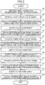
- FIG. 2 is a flowchart for describing an operation of the acoustic echo cancellation device according to the first embodiment of this disclosure.
- step S2 the adaptive filter 161 of the first echo canceller 16 produces a first pseudo echo signal which indicates a component of a reproduced signal contained in an addition signal by convoluting a filter coefficient and the reproduced signal.
- step S3 the error calculation part 162 calculates an error signal between the addition signal from the adder 13 and the first pseudo echo signal from the adaptive filter 161 by subtracting the first pseudo echo signal from the addition signal.
- the error calculation part 162 outputs the calculated error signal to the adaptive filter 161.
- step S4 the adaptive filter 161 modifies a filter coefficient based on the error signal inputted from the error calculation part 162.
- the adaptive filter 161 produces the first pseudo echo signal by convoluting the modified filter coefficient and the reproduced signal.
- step S5 the adaptive filter 161 outputs the produced first pseudo echo signal to the third echo canceller 18 and the fourth echo canceller 19.
- step S6 the adaptive filter 181 of the third echo canceller 18 produces a third pseudo echo signal which indicates a component of the first pseudo echo signal contained in the first input signal by convoluting the filter coefficient and the first pseudo echo signal.
- step S7 the error calculation part 182 calculates an error signal between the first input signal from the first microphone 11 and the third pseudo echo signal from the adaptive filter 181 by subtracting the third pseudo echo signal from the first input signal.
- the error calculation part 182 outputs the calculated error signal to the adaptive filter 181.
- step S8 the adaptive filter 181 modifies a filter coefficient based on the error signal inputted from the error calculation part 182.
- the adaptive filter 181 produces the third pseudo echo signal by convoluting the modified filter coefficient and the first pseudo echo signal.
- step S9 the error calculation part 182 outputs the first input signal in which the acoustic echo component is cancelled to the first output terminal 20. That is, the error calculation part 182 cancels an acoustic echo component from the first input signal by subtracting the third pseudo echo signal from the adaptive filter 181 from the first input signal from the first microphone 11.
- step S10 the adaptive filter 191 of the fourth echo canceller 19 produces a fourth pseudo echo signal which indicates a component of the first pseudo echo signal contained in the second input signal by convoluting the filter coefficient and the first pseudo echo signal.
- step S11 the error calculation part 192 calculates an error signal between the second input signal from the second microphone 12 and the fourth pseudo echo signal from the adaptive filter 191 by subtracting the fourth pseudo echo signal from the second input signal.
- the error calculation part 192 outputs the calculated error signal to the adaptive filter 191.
- step S12 the adaptive filter 191 modifies a filter coefficient based on the error signal inputted from the error calculation part 192.
- the adaptive filter 191 produces the fourth pseudo echo signal by convoluting the modified filter coefficient and the first pseudo echo signal.
- step S13 the error calculation part 192 outputs the second input signal in which the acoustic echo component is cancelled to the second output terminal 21. That is, the error calculation part 192 cancels an acoustic echo component from the second input signal by subtracting the fourth pseudo echo signal from the adaptive filter 191 from the second input signal from the second microphone 12.
- the filter coefficient is not sufficiently modified. Accordingly, an acoustic echo component cannot be sufficiently cancelled from the first input signal and the second input signal. However, by repeatedly performing processing in step S1 to step S13, the filter coefficient is sufficiently modified and hence, the acoustic echo component can be sufficiently cancelled from the first input signal and the second input signal.
- the first echo canceller 16 produces the first pseudo echo signal which indicates a component of the reproduced signal contained in the input signals obtained from at least two microphones
- the second echo canceller 17 produces a second pseudo echo signal which indicates a component of the first pseudo echo signal contained in at least one input signal, and cancels an acoustic echo component of at least one input signal using the produced second pseudo echo signal.
- the second pseudo echo signal is produced using the already produced first pseudo echo signal. Accordingly, a filter length (tap length) of the adaptive filter used in producing the second pseudo echo signal can be shortened and hence, a conversation performance can be maintained and, at the same time, an arithmetic amount for removing an acoustic echo can be reduced.
- echo cancelling processing by the echo canceller on a first stage has substantially the same filter length (arithmetic amount) compared to the prior art.
- echo cancelling processing by the echo cancellers on the second stage and succeeding stages uses the already produced first pseudo echo signal and hence, can have a short filter length compared to the prior art.
- an arithmetic amount can be reduced compared to the prior art. Accordingly, the larger the number of microphone becomes, the smaller an arithmetic amount becomes compared to the prior art.
- the first echo canceller 16 produces a first pseudo echo signal using an addition signal obtained by adding a first input signal from the first microphone 11 and a second input signal from the second microphone 12 and a reproduced signal transmitted to the speaker 15. In this case, it is considered that an acoustic echo inputted to a virtual microphone disposed at an intermediate position between the first microphone 11 and the second microphone 12 from the speaker 15 is estimated.
- the third echo canceller 18 produces a third pseudo echo signal using a first pseudo echo signal produced by the first echo canceller 16. In this case, it is considered that an acoustic echo corresponding to a differential between the position of a virtual microphone and the position of the first microphone 11 is estimated.
- a filter length of the adaptive filter 181 of the third echo canceller 18 can be set largely shorter than a filter length of the adaptive filter 161 of the first echo canceller 16.
- a filter length of the adaptive filter 191 of the fourth echo canceller 19 can be set largely shorter than the filter length of the adaptive filter 161 of the first echo canceller 16.
- arithmetic amounts of the third echo canceller 18 and the fourth echo canceller 19 can be reduced to approximately one tenth of an arithmetic amount of the first echo canceller 16. Accordingly, a total arithmetic amount of the first echo canceller 16, the third echo canceller 18, and the fourth echo canceller 19 can be set sufficiently small compared to a total arithmetic amount in the case where two echo cancellers having the same arithmetic amount as the first echo canceller 16 are provided to the first microphone 11 and the second microphone 12 respectively.
- the arrangement positions of the plurality of microphones differ from each other. Accordingly, a waveform of a reflected wave (echo signal) inputted as an acoustic echo differs between the plurality of microphones.
- a phase of an echo signal is opposite to a phase of an input signal which is a voice of a talker
- the input signal is eliminated. Accordingly, it is difficult to cancel an acoustic echo of the input signal.
- a first input signal and a second input signal from at least two microphones are added and hence, an effect of loss of a signal caused by interference of acoustic echoes can be reduced.
- a reproduced signal in a time domain and an addition signal in a time domain are inputted to the first echo canceller 16, and a first input signal in a time domain, a second input signal in the time domain, and a first pseudo echo signal in the time domain are inputted to the second echo canceller 17.
- this disclosure is not particularly limited to such a case.
- a reproduced signal in a frequency domain and an addition signal in the frequency domain may be inputted to the first echo canceller 16, and a first input signal in the frequency domain, a second input signal in the frequency domain, and a first pseudo echo signal in the frequency domain may be inputted to the second echo canceller 17.
- a modification 1 of the first embodiment is described.
- FIG. 3 is a view showing the configuration of a conversation device according to the modification 1 of the first embodiment of this disclosure.
- the conversation device shown in FIG. 3 includes an acoustic echo cancellation device 1A, a first microphone 11, a second microphone 12, an input terminal 14, a speaker 15, a first output terminal 20, and a second output terminal 21.
- constitutional elements equal to the corresponding constitutional elements of the first embodiment are given the same symbols, and the description of these constitutional elements is omitted.
- the acoustic echo cancellation device 1A includes an adder 13, a first echo canceller 16, a second echo canceller 17, fast Fourier transform parts 24, 25, 28, 29, and inverse fast Fourier transform parts 30, 31.
- the fast Fourier transform parts 24, 25, 28, 29 perform a discrete Fourier transform at a high speed.
- the fast Fourier transform part 24 transforms a reproduced signal in a time domain inputted to the first echo canceller 16 into a reproduced signal in a frequency domain.
- the fast Fourier transform part 25 transforms an addition signal (input signal) in a time domain inputted from the adder 13 to the first echo canceller 16 into an addition signal (input signal) in a frequency domain.
- the fast Fourier transform part 28 coverts a first input signal (at least one input signal) in a time domain inputted from the first microphone 11 to a third echo canceller 18 into a first input signal (at least one input signal) in a frequency domain.
- the fast Fourier transform part 29 transforms a second input signal (at least one input signal) in a time domain inputted from the second microphone 12 to a fourth echo canceller 19 into a second input signal (at least one input signal) in a frequency domain.
- the inverse fast Fourier transform parts 30, 31 perform an inverse discrete Fourier transform at a high speed.
- the inverse fast Fourier transform part 30 transforms a first input signal in a frequency domain inputted from the third echo canceller 18 to the first output terminal 20 into a first input signal in a time domain.
- the inverse fast Fourier transform part 31 transforms a second input signal in a frequency domain inputted from the fourth echo canceller 19 to the second output terminal 21 into a second input signal in a time domain.
- the first echo canceller 16 produces a first pseudo echo signal in a frequency domain using an addition signal in a frequency domain and a reproduced signal in a frequency domain.
- the third echo canceller 18 produces a third pseudo echo signal in a frequency domain using a first input signal in a frequency domain and a first pseudo echo signal in a frequency domain, and cancels an acoustic echo component of the first input signal in a frequency domain using the produced third pseudo echo signal in the frequency domain.
- the fourth echo canceller 19 produces a fourth pseudo echo signal in a frequency domain using a second input signal in a frequency domain and a first pseudo echo signal in a frequency domain, and cancels an acoustic echo component of the second input signal in the frequency domain using the produced fourth pseudo echo signal in the frequency domain.
- adaptive filters 161, 181, 191 can use an adaptive algorithm in a frequency domain, and a convolution operation can be performed by multiplication and hence, an arithmetic amount can be further reduced.
- the acoustic echo cancellation device may further include a delay part which delays at least one input signal outputted from at least two microphones.
- FIG. 10 is a view showing the configuration of a conversation device according to a modification 2 of the first embodiment of this disclosure.
- the conversation device shown in FIG. 10 includes an acoustic echo cancellation device IF, a first microphone 11, a second microphone 12, an input terminal 14, a speaker 15, a first output terminal 20, and a second output terminal 21.
- constitutional elements equal to the corresponding constitutional elements of the first embodiment are given the same symbols, and the description of these constitutional elements is omitted.
- the acoustic echo cancellation device IF includes an adder 13, a first echo canceller 16, a second echo canceller 17, and a delay part 80.
- the first delay part 81 is disposed between the first microphone 11 and a third echo canceller 18.
- the first delay part 81 delays a first input signal from the first microphone 11.
- the second delay part 82 is disposed between the second microphone 12 and a fourth echo canceller 19.
- the second delay part 82 delays a second input signal from the second microphone 12.
- the second echo canceller 17 produces a second pseudo echo signal which indicates a component of a first pseudo echo signal contained in at least one delayed input signal using at least one delayed input signal and the first pseudo echo signal produced by the first echo canceller 16, and cancels an acoustic echo component of at least one delayed input signal using the produced second pseudo echo signal.
- the third echo canceller 18 produces a third pseudo echo signal which indicates a component of a first pseudo echo signal contained in a delayed first input signal using the delayed first input signal and the first pseudo echo signal produced by the first echo canceller 16, and cancels an acoustic echo component of the delayed first input signal using the produced third pseudo echo signal.
- the fourth echo canceller 19 produces a fourth pseudo echo signal which indicates a component of a first pseudo echo signal contained in a delayed second input signal using the delayed second input signal and the first pseudo echo signal produced by the first echo canceller 16, and cancels an acoustic echo component of the delayed second input signal using the produced fourth pseudo echo signal.
- a first input signal delayed by the first delay part 81 is inputted to the third echo canceller 18, and a second input signal delayed by the second delay part 82 is inputted to the fourth echo canceller 19. Accordingly, a time difference between the first pseudo echo signal produced by the first echo canceller 16 and the first input signal is eliminated, and a time difference between the first pseudo echo signal and the second input signal is eliminated and hence, it is possible to produce a third pseudo echo signal and a fourth pseudo echo signal with certainty.
- the acoustic echo cancellation device 1A may include the first delay part 81 between the first microphone 11 and the fast Fourier transform part 28, and may include the second delay part 82 between the second microphone 12 and the fast Fourier transform part 29.
- the adder 13 adds a first input signal from the first microphone 11 and a second input signal from the second microphone 12 to each other, and the first echo canceller 16 produces a first pseudo echo signal which indicates a component of a reproduced signal contained in an addition signal using the addition signal and the reproduced signal.
- the acoustic echo cancellation device 1 may further include an averaging processing part which averages the addition signal from the adder 13.
- the first echo canceller 16 may produce a first pseudo echo signal which indicates a component of a reproduced signal contained in an averaging signal using the averaging signal from the averaging processing part and the reproduced signal.
- a first pseudo echo signal produced by the first echo canceller is outputted to the third echo canceller and the fourth echo canceller, the third echo canceller cancels an acoustic echo component of a first input signal using the first pseudo echo signal, and the fourth echo canceller cancels an acoustic echo component of a second input signal using the first pseudo echo signal.
- the first echo canceller produces a first pseudo echo signal, cancels an acoustic echo component of a first input signal using the first pseudo echo signal
- the second echo canceller cancels an acoustic echo component of a second input signal using the first pseudo echo signal.
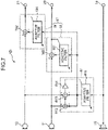
- FIG. 4 is a view showing the configuration of a conversation device according to the second embodiment of this disclosure.
- the conversation device shown in FIG. 4 includes an acoustic echo cancellation device IB, a first microphone 11, a second microphone 12, an input terminal 14, a speaker 15, a first output terminal 20, and a second output terminal 21.
- constitutional elements equal to the corresponding constitutional elements of the first embodiment are given the same symbols, and the description of these constitutional elements is omitted.
- the acoustic echo cancellation device 1B includes a first echo canceller 41 and a second echo canceller 42.
- the first echo canceller 41 produces a first pseudo echo signal which indicates a component of a reproduced signal contained in an input signal using an input signal obtained from at least two microphones and a reproduced signal outputted to the speaker.
- the first echo canceller 41 produce a first pseudo echo signal with respect to the microphone disposed at the position closest to the speaker 15.
- the first echo canceller 41 produces a first pseudo echo signal which indicates a component of a reproduced signal contained in an input signal using the input signal outputted from the microphone disposed at the position closest to the speaker 15 and the reproduced signal.
- the microphone disposed at the position closest to the speaker 15 is the first microphone 11.
- an input signal obtained from at least two microphones is a first input signal from the first microphone 11. That is, the first echo canceller 41 produces a first pseudo echo signal which indicates a component of a reproduced signal contained in the first input signal using the first input signal and the reproduced signal. Further, the first echo canceller 41 cancels an acoustic echo component of the first input signal using the produced first pseudo echo signal.
- the first echo canceller 41 includes an adaptive filter 411 and an error calculation part 412.
- the adaptive filter 411 produces a first pseudo echo signal which indicates a component of a reproduced signal contained in a first input signal by convoluting a filter coefficient and the reproduced signal.
- the error calculation part 412 calculates an error signal between the first input signal from the first microphone 11 and the first pseudo echo signal from the adaptive filter 411, and outputs a calculated error signal to the adaptive filter 411.
- the adaptive filter 411 modifies a filter coefficient based on an inputted error signal, and produces a first pseudo echo signal by convoluting a modified filter coefficient and a reproduced signal.
- the adaptive filter 411 modifies the filter coefficient such that the error signal is minimized using an adaptive algorithm.
- the adaptive algorithm for example, an NLMS method, an AP method, or an RLS method can be used.
- the error calculation part 412 cancels an acoustic echo component from a first input signal by subtracting a first pseudo echo signal from the adaptive filter 411 from a first input signal from the first microphone 11. Accordingly, the error calculation part 412 outputs a first input signal in which an acoustic echo component is cancelled to the first output terminal 20.
- a first pseudo echo signal produced by the first echo canceller 41 is outputted to the second echo canceller 42.
- the second echo canceller 42 produces a second pseudo echo signal which indicates a component of a first pseudo echo signal contained in a second input signal using a second input signal and a first pseudo echo signal produced by the first echo canceller 41, and cancels an acoustic echo component of a second input signal using a produced second pseudo echo signal.
- the second echo canceller 42 includes an adaptive filter 421 and an error calculation part 422.
- the adaptive filter 421 produces a second pseudo echo signal which indicates a component of the first pseudo echo signal contained in the second input signal by convoluting a filter coefficient and the first pseudo echo signal.
- the error calculation part 422 calculates an error signal between a second input signal from a second microphone 12 and the second pseudo echo signal from the adaptive filter 421, and outputs the calculated error signal to the adaptive filter 421.
- the adaptive filter 421 modifies a filter coefficient based on an inputted error signal, and produces a second pseudo echo signal by convoluting a modified filter coefficient and a first pseudo echo signal.
- the adaptive filter 421 modifies a filter coefficient such that an error signal is minimized using an adaptive algorithm.
- the adaptive algorithm for example, an NLMS method, an AP method, or an RLS method can be used.
- the error calculation part 422 cancels an acoustic echo component from a second input signal by subtracting a second pseudo echo signal from the adaptive filter 421 from a second input signal from the second microphone 12. Accordingly, the error calculation part 422 outputs a second input signal in which an acoustic echo component is cancelled to the second output terminal 21.
- the conversation device includes two microphones.
- this disclosure is not particularly limited to such a case, and the conversation device may include three or more microphones.
- the first echo canceller 41 outputs a first pseudo echo signal to echo cancellers which are provided to the respective microphones other than the first microphone 11.
- the conversation device includes one speaker.
- this disclosure is not particularly limited to such a case, and the conversation device may include two or more speakers.
- the conversation device includes a plurality of speakers, it is necessary for the conversation device to include the same number of acoustic echo cancellation devices 1B as the plurality of speakers.
- FIG. 5 is a flowchart for describing an operation of the acoustic echo cancellation device according to the second embodiment of this disclosure.
- step S21 the adaptive filter 411 of the first echo canceller 41 produces a first pseudo echo signal which indicates a component of a reproduced signal contained in a first input signal by convoluting a filter coefficient and the reproduced signal.
- step S22 the error calculation part 412 calculates an error signal between a first input signal from the first microphone 11 and a first pseudo echo signal from the adaptive filter 411 by subtracting the first pseudo echo signal from the first input signal.
- the error calculation part 412 outputs the calculated error signal to the adaptive filter 411.
- the adaptive filter 411 modifies a filter coefficient based on an error signal inputted from the error calculation part 412.
- the adaptive filter 411 produces a first pseudo echo signal by convoluting a modified filter coefficient and a reproduced signal.
- step S24 the error calculation part 412 outputs a first input signal in which an acoustic echo component is cancelled to the first output terminal 20. That is, the error calculation part 412 cancels an acoustic echo component from a first input signal by subtracting a first pseudo echo signal from the adaptive filter 411 from a first input signal from the first microphone 11.
- step S25 the adaptive filter 411 outputs a produced first pseudo echo signal to a second echo canceller 42.
- step S26 the adaptive filter 421 of the second echo canceller 42 produces a second pseudo echo signal which indicates a component of the first pseudo echo signal contained in the second input signal by convoluting a filter coefficient and a first pseudo echo signal.
- step S27 the error calculation part 422 calculates an error signal between a second input signal from the second microphone 12 and a second pseudo echo signal from the adaptive filter 421 by subtracting the second pseudo echo signal from the second input signal.
- the error calculation part 422 outputs the calculated error signal to the adaptive filter 421.
- step S28 the adaptive filter 421 modifies a filter coefficient based on the error signal inputted from the error calculation part 422.
- the adaptive filter 421 produces the second pseudo echo signal by convoluting the modified filter coefficient and the first pseudo echo signal.
- step S29 the error calculation part 422 outputs the second input signal in which the acoustic echo component is cancelled to the second output terminal 21. That is, the error calculation part 422 cancels an acoustic echo component from the second input signal by subtracting the second pseudo echo signal from the adaptive filter 421 from the second input signal from the second microphone 12.
- the filter coefficient is not sufficiently modified. Accordingly, an acoustic echo component cannot be sufficiently cancelled from the first input signal and the second input signal. However, by repeatedly performing processing in step S21 to step S29, the filter coefficient is sufficiently modified and hence, the acoustic echo component can be sufficiently cancelled from the first input signal and the second input signal.
- the first echo canceller 41 produces the first pseudo echo signal which indicates a component of the reproduced signal contained in the first input signal obtained from the first microphone 11, and cancels the acoustic echo component of the first input signal using the produced first pseudo echo signal
- the second echo canceller 42 produces a second pseudo echo signal which indicates a component of the first pseudo echo signal contained in the second input signal, and cancels an acoustic echo component of the second input signal using the produced second pseudo echo signal.
- the second pseudo echo signal is produced using the already produced first pseudo echo signal. Accordingly, a filter length (tap length) of the adaptive filter used in producing the second pseudo echo signal can be shortened and hence, a conversation performance can be maintained and, at the same time, an arithmetic amount for removing an acoustic echo can be reduced.
- echo cancelling processing by the echo canceller on a first stage has substantially the same filter length (arithmetic amount) compared to the prior art.
- echo cancelling processing by the echo cancellers on the second stage and succeeding stages uses the already produced first pseudo echo signal and hence, can have a short filter length compared to the prior art.
- an arithmetic amount can be reduced compared to the prior art. Accordingly, the larger the number of microphone becomes, the smaller an arithmetic amount becomes compared to the prior art.
- the first echo canceller 41 produces a first pseudo echo signal using a first input signal from the first microphone 11 and the reproduced signal transmitted to the speaker 15. In this case, it is considered that an acoustic echo inputted to the first microphone 11 from the speaker 15 is estimated.
- the second echo canceller 42 produces a second pseudo echo signal using a first pseudo echo signal produced by the first echo canceller 16. In this case, it is considered that an acoustic echo corresponding to a differential between the position of the first microphone 11 and the position of the second microphone 12 is estimated. Accordingly, a filter length of the adaptive filter 421 of the second echo canceller 42 can be set largely shorter than a filter length of the adaptive filter 411 of the first echo canceller 41.
- an arithmetic amount of the second echo canceller 42 can be reduced to approximately one tenth of an arithmetic amount of the first echo canceller 41. Accordingly, a total arithmetic amount of the first echo canceller 41 and the second echo canceller 42 can be set sufficiently small compared to a total arithmetic amount in the case where two echo cancellers having the same arithmetic amount as the first echo canceller 41 are provided to the first microphone 11 and the second microphone 12 respectively.
- the acoustic echo cancellation device IB may include a delay part between the second microphone 12 and the second echo canceller 42.
- a reproduced signal in a time domain and a first input signal in a time domain are inputted to the first echo canceller 41, and a second input signal in the time domain and a first pseudo echo signal in the time domain are inputted to the second echo canceller 42.
- this disclosure is not particularly limited to such a case.
- a reproduced signal in a frequency domain and a first input signal in a frequency domain may be inputted to the first echo canceller 41, and a second input signal in a frequency domain and a first pseudo echo signal in a frequency domain may be inputted to the second echo canceller 42.
- a modification of the second embodiment is described.
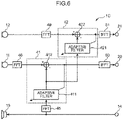
- FIG. 6 is a view showing the configuration of a conversation device according to a modification of the second embodiment of this disclosure.
- the conversation device shown in FIG. 6 includes an acoustic echo cancellation device 1C, a first microphone 11, a second microphone 12, an input terminal 14, a speaker 15, a first output terminal 20, and a second output terminal 21.
- constitutional elements equal to the corresponding constitutional elements of the second embodiment are given the same symbols, and the description of these constitutional elements is omitted.
- the acoustic echo cancellation device 1C includes a first echo canceller 41, a second echo canceller 42, fast Fourier transform parts 45, 46, 49, and inverse fast Fourier transform parts 50, 51.
- the fast Fourier transform parts 45, 46, 49 perform a discrete Fourier transform at a high speed.
- the fast Fourier transform part 45 transforms a reproduced signal in a time domain inputted to the first echo canceller 41 into a reproduced signal in a frequency domain.
- the fast Fourier transform part 46 transforms a first input signal in a time domain inputted from the first microphone 11 to the first echo canceller 41 into a first input signal in a frequency domain.
- the fast Fourier transform part 49 transforms a second input signal in a time domain inputted from the second microphone 12 to the second echo canceller 42 into a second input signal in a frequency domain.
- the inverse fast Fourier transform parts 50, 51 perform an inverse discrete Fourier transform at a high speed.
- the inverse fast Fourier transform part 50 transforms a first input signal in a frequency domain inputted from the first echo canceller 41 to the first output terminal 20 into a first input signal in a time domain.
- the inverse fast Fourier transform part 51 transforms a second input signal in a frequency domain inputted from the second echo canceller 42 to the second output terminal 21 into a second input signal in a time domain.
- the first echo canceller 41 produces a first pseudo echo signal in a frequency domain using a first input signal in a frequency domain and a reproduced signal in a frequency domain, and cancels an acoustic echo component of the first input signal in a frequency domain using the produced first pseudo echo signal in a frequency domain.
- the second echo canceller 42 produces a second pseudo echo signal in a frequency domain using the second input signal in a frequency domain and the first pseudo echo signal in a frequency domain, and cancels an acoustic echo component of the second input signal in a frequency domain using the produced second pseudo echo signal in a frequency domain.
- adaptive filters 411, 421 can use an adaptive algorithm in a frequency domain, and a convolution operation can be performed by multiplication and hence, an arithmetic amount can be further reduced.
- the acoustic echo cancellation device 1C may include a delay part between the second microphone 12 and the fast Fourier transform part 49.
- the first echo canceller produces a first pseudo echo signal which indicates a component of a reproduced signal contained in an addition signal using the addition signal from the adder and the reproduced signal.
- the first echo canceller calculates a first error signal which indicates an error between a first input signal and a first pseudo echo signal, calculates a second error signal which indicates an error between a second input signal and a first pseudo echo signal, averages an addition signal obtained by adding the first error signal and the second error signal to each other, and produces the first pseudo echo signal which indicates a component of a reproduced signal contained in the average signal using the average signal and the reproduced signal.
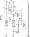
- FIG. 7 is a view showing the configuration of a conversation device according to the third embodiment of this disclosure.
- the conversation device shown in FIG. 7 includes an acoustic echo cancellation device ID, a first microphone 11, a second microphone 12, an input terminal 14, a speaker 15, a first output terminal 20, and a second output terminal 21.
- constitutional elements equal to the corresponding constitutional elements of the first embodiment are given the same symbols, and the description of these constitutional elements is omitted.
- the acoustic echo cancellation device ID includes a first echo canceller 61, and a second echo canceller 17.
- the first echo canceller 61 produces a first pseudo echo signal which indicates a component of the reproduced signal contained in the input signal using an input signal obtained from at least two microphones and a reproduced signal outputted to the speaker.
- an input signal obtained from at least two microphones is an average signal obtained by averaging an addition signal which is obtained by adding a first error signal which indicates an error between a first input signal and a first pseudo echo signal and a second error signal which indicates an error between a second input signal and the first pseudo echo signal to each other. That is, the first echo canceller 61 produces a first pseudo echo signal which indicates a component of a reproduced signal contained in an average signal using an average signal and the reproduced signal.
- the first echo canceller 61 includes an adaptive filter 611, a first error calculation part 612, a second error calculation part 613, and an averaging processing part 614.
- the adaptive filter 611 produces a first pseudo echo signal which indicates a component of a reproduced signal contained in an average signal by convoluting a filter coefficient and the reproduced signal.
- the first error calculation part 612 calculates a first error signal which indicates an error between a first input signal and a first pseudo echo signal.
- the first error calculation part 612 outputs the calculated first error signal to the second error calculation part 613.
- the second error calculation part 613 calculates a second error signal which indicates an error between a second input signal and a first pseudo echo signal, and adds the first error signal and the second error signal to each other.
- the second error calculation part 613 outputs an addition signal obtained by adding a first error signal and a second error signal to each other to the averaging processing part 614.
- the averaging processing part 614 averages the addition signal obtained by adding the first error signal and the second error signal to each other.
- the averaging processing part 614 outputs an average signal obtained by averaging an addition signal which is obtained by adding a first error signal and a second error signal to each other to the adaptive filter 611.
- the adaptive filter 611 produces a first pseudo echo signal which indicates a component of a reproduced signal contained in an average signal using an average signal from the averaging processing part 614 and a reproduced signal.
- the adaptive filter 611 modifies a filter coefficient based on an inputted average signal, and produces a first pseudo echo signal by convoluting a modified filter coefficient and a reproduced signal.
- the adaptive filter 611 modifies a filter coefficient such that an average signal is minimized using an adaptive algorithm.
- the adaptive algorithm for example, an NLMS method, an AP method, or an RLS method can be used.
- a first pseudo echo signal produced by the first echo canceller 61 is outputted to the third echo canceller 18 and the fourth echo canceller 19.
- the conversation device includes two microphones.
- this disclosure is not particularly limited to such a case, and the conversation device may include three or more microphones.
- the first echo canceller 61 performs adding and averaging of error signals between respective input signals from three or more microphones and a first pseudo echo signal, and outputs the first pseudo echo signal to echo cancellers which are provided to the respective three or more microphones.
- the conversation device includes one speaker.
- this disclosure is not particularly limited to such a case, and the conversation device may include two or more speakers.
- the conversation device includes a plurality of speakers, it is necessary for the conversation device to include the same number of acoustic echo cancellation devices ID as the plurality of speakers.
- FIG. 8 is a flowchart for describing an operation of the acoustic echo cancellation device according to the third embodiment of this disclosure.
- step S41 the adaptive filter 611 of the first echo canceller 61 produces a first pseudo echo signal which indicates a component of a reproduced signal contained in an average signal by convoluting a filter coefficient and the reproduced signal.
- step S42 the first error calculation part 612 calculates a first error signal which is a differential between the first input signal from the first microphone 11 and the first pseudo echo signal from the adaptive filter 611 by subtracting the first pseudo echo signal from the first input signal.
- the first error calculation part 612 outputs the calculated first error signal to the second error calculation part 613.
- step S43 the second error calculation part 613 calculates a second error signal which is a differential between the second input signal from the second microphone 12 and the first pseudo echo signal from the adaptive filter 611 by subtracting the first pseudo echo signal from the second input signal.
- step S44 the second error calculation part 613 adds the first error signal and the second error signal.
- the second error calculation part 613 outputs a calculated addition signal obtained by adding the first error signal and the second error signal to each other to the averaging processing part 614.
- step S45 the averaging processing part 614 averages the addition signal obtained by adding the first error signal and the second error signal to each other.
- the averaging processing part 614 outputs an average signal obtained by averaging the addition signal to the adaptive filter 611.
- step S46 the adaptive filter 611 modifies a filter coefficient based on the average signal inputted from the averaging processing part 614.
- the adaptive filter 611 produces the first pseudo echo signal by convoluting the modified filter coefficient and the reproduced signal.
- step S47 the adaptive filter 611 outputs the produced first pseudo echo signal to the third echo canceller 18 and the fourth echo canceller 19.
- step S48 the adaptive filter 181 of the third echo canceller 18 produces a third pseudo echo signal which indicates a component of the first pseudo echo signal contained in the first input signal by convoluting the filter coefficient and the first pseudo echo signal.
- step S49 the error calculation part 182 calculates a third error signal between the first input signal from the first microphone 11 and the third pseudo echo signal from the adaptive filter 181 by subtracting the third pseudo echo signal from the first input signal.
- the error calculation part 182 outputs the calculated third error signal to the adaptive filter 181.
- step S50 the adaptive filter 181 modifies a filter coefficient based on the third error signal inputted from the error calculation part 182.
- the adaptive filter 181 produces the third pseudo echo signal by convoluting the modified filter coefficient and the first pseudo echo signal.
- step S51 the error calculation part 182 outputs the first input signal in which the acoustic echo component is cancelled to the first output terminal 20. That is, the error calculation part 182 cancels an acoustic echo component from the first input signal by subtracting the third pseudo echo signal from the adaptive filter 181 from the first input signal from the first microphone 11.
- step S52 the adaptive filter 191 of the fourth echo canceller 19 produces a fourth pseudo echo signal which indicates a component of the first pseudo echo signal contained in the second input signal by convoluting the filter coefficient and the first pseudo echo signal.
- step S53 the error calculation part 192 calculates a fourth error signal between the second input signal from the second microphone 12 and the fourth pseudo echo signal from the adaptive filter 191 by subtracting the fourth pseudo echo signal from the second input signal.
- the error calculation part 192 outputs the calculated fourth error signal to the adaptive filter 191.
- step S54 the adaptive filter 191 modifies a filter coefficient based on the fourth error signal inputted from the error calculation part 192.
- the adaptive filter 191 produces the fourth pseudo echo signal by convoluting the modified filter coefficient and the first pseudo echo signal.
- step S55 the error calculation part 192 outputs the second input signal in which the acoustic echo component is cancelled to the second output terminal 21. That is, the error calculation part 192 cancels an acoustic echo component from the second input signal by subtracting the fourth pseudo echo signal from the adaptive filter 191 from the second input signal from the second microphone 12.
- the filter coefficient is not sufficiently modified. Accordingly, an acoustic echo component cannot be sufficiently cancelled from the first input signal and the second input signal. However, by repeatedly performing processing in step S41 to step S55, the filter coefficient is sufficiently modified and hence, the acoustic echo component can be sufficiently cancelled from the first input signal and the second input signal.
- the first echo canceller 61 produces the first pseudo echo signal which indicates a component of the reproduced signal contained in the input signals obtained from at least two microphones
- the second echo canceller 17 produces a second pseudo echo signal which indicates a component of the first pseudo echo signal contained in at least one input signal, and cancels an acoustic echo component of at least one input signal using the produced second pseudo echo signal.
- the second pseudo echo signal is produced using the already produced first pseudo echo signal. Accordingly, a filter length (tap length) of the adaptive filter used in producing the second pseudo echo signal can be shortened and hence, a conversation performance can be maintained and, at the same time, an arithmetic amount for removing an acoustic echo can be reduced.
- echo cancelling processing by the echo canceller on a first stage has substantially the same filter length (arithmetic amount) compared to the prior art.
- echo cancelling processing by the echo cancellers on the second stage and succeeding stages uses the already produced first pseudo echo signal and hence, can have a short filter length compared to the prior art.
- an arithmetic amount can be reduced compared to the prior art. Accordingly, the larger the number of microphone becomes, the smaller an arithmetic amount becomes compared to the prior art.
- the arrangement positions of the plurality of microphones differ from each other. Accordingly, a waveform of a reflected wave (echo signal) inputted as an acoustic echo differs between the plurality of microphones.
- a phase of an echo signal is opposite to a phase of an input signal which is a voice of a talker
- the input signal is eliminated. Accordingly, it is difficult to cancel an acoustic echo of the input signal.
- the respective error signals of the first input signal and the second input signal from at least two microphones are added to each other and are averaged and hence, an effect of loss of a signal caused by interference of acoustic echoes can be reduced.
- the acoustic echo cancellation device ID may include a first delay part 81 between the first microphone 11 and the third echo canceller 18, or may include a second delay part 82 between the second microphone 12 and the fourth echo canceller 19.
- a reproduced signal in a time domain, a first input signal in the time domain, and a second input signal in the time domain are inputted to the first echo canceller 61, and a first input signal in a time domain, a second input signal in the time domain, and a first pseudo echo signal in the time domain are inputted to the second echo canceller 17.
- this disclosure is not particularly limited to such a case.
- a reproduced signal in a frequency domain, a first input signal in the frequency domain, and a second input signal in the frequency domain may be inputted to the first echo canceller 61, and a first input signal in a frequency domain, a second input signal in the frequency domain, and a first pseudo echo signal in the frequency domain may be inputted to the second echo canceller 17.
- a modification of the third embodiment is described.
- FIG. 9 is a view showing the configuration of a conversation device according to a modification of the third embodiment of this disclosure.
- the conversation device shown in FIG. 9 includes an acoustic echo cancellation device IE, a first microphone 11, a second microphone 12, an input terminal 14, a speaker 15, a first output terminal 20, and a second output terminal 21.
- constitutional elements equal to the corresponding constitutional elements of the third embodiment are given the same symbols, and the description of these constitutional elements is omitted.
- the acoustic echo cancellation device IE includes a first echo canceller 61, a second echo canceller 17, fast Fourier transform parts 64, 65, 66, and inverse fast Fourier transform parts 69, 70.
- the fast Fourier transform parts 64, 65, 66 perform a discrete Fourier transform at a high speed.
- the fast Fourier transform part 64 transforms a reproduced signal in a time domain inputted to the first echo canceller 61 into a reproduced signal in a frequency domain.
- the fast Fourier transform part 65 transforms a first input signal in a time domain outputted from the first microphone 11 into a first input signal in a frequency domain.
- the fast Fourier transform part 66 transforms a second input signal in a time domain outputted from the second microphone 12 into a second input signal in a frequency domain.
- the inverse fast Fourier transform parts 69, 70 perform an inverse discrete Fourier transform at a high speed.
- the inverse fast Fourier transform part 69 transforms a first input signal in a frequency domain inputted from the third echo canceller 18 to the first output terminal 20 into a first input signal in a time domain.
- the inverse fast Fourier transform part 70 transforms a second input signal in a frequency domain inputted from the fourth echo canceller 19 to the second output terminal 21 into a second input signal in a time domain.
- the first echo canceller 61 produces a first pseudo echo signal in a frequency domain using a first input signal in a frequency domain, and a second input signal in a frequency domain, and a reproduced signal in a frequency domain.
- the third echo canceller 18 produces a third pseudo echo signal in a frequency domain using a first input signal in a frequency domain and a first pseudo echo signal in a frequency domain, and cancels an acoustic echo component of the first input signal in a frequency domain using the produced third pseudo echo signal in the frequency domain.
- the fourth echo canceller 19 produces a fourth pseudo echo signal in a frequency domain using a second input signal in a frequency domain and a first pseudo echo signal in a frequency domain, and cancels an acoustic echo component of the second input signal in the frequency domain using the produced fourth pseudo echo signal in the frequency domain.
- adaptive filters 611, 181, 191 can use an adaptive algorithm in a frequency domain, and a convolution operation can be performed by multiplication and hence, an arithmetic amount can be further reduced.
- the acoustic echo cancellation device IE may include the first delay part 81 between the first microphone 11 and the third echo canceller 18, and may include the second delay part 82 between the second microphone 12 and the fourth echo canceller 19.
- the fast Fourier transform part 65 is disposed between a branch point between the first microphone 11 and the error calculation part 182 and the first error calculation part 612, and the first delay part 81 and the fast Fourier transform part are disposed between the branch point and the error calculation part 182.
- the fast Fourier transform part 66 is disposed between a branch point between the second microphone 12 and the error calculation part 192 and the second error calculation part 613, and the second delay part 82 and the fast Fourier transform part are disposed between the branch point and the error calculation part 192.
- each constitutional element may be formed of a dedicated hardware, or may be realized by executing a software program suitable for each constitutional element.
- Each constitutional element may be realized by allowing a program executing part such as a CPU or a processor to read a software program recorded in a recording medium such as a hard disc or a semiconductor memory and to execute the software program.
- a part or the entirety of functions of the device according to the embodiment of this disclosure is typically realized in the form of large scale integration (LSI) which is an integrated circuit.
- LSI large scale integration
- These constitutional parts may be individually formed as one chip or may be formed as one chip such that one chip includes some of or all constitutional elements.
- the integrated circuit is not limited to LSI, and may be realized in the form of a dedicated circuit or a general-purpose processor. It is also possible to use a Field Programmable Gate Array (FPGA) which is programmable after manufacturing an LSI or a reconfigurable processor capable of reconstructing the connection and the setting of circuit cells in an LSI.
- FPGA Field Programmable Gate Array
- a part of or the entirety of functions of the device according to the embodiment of this disclosure may be realized by allowing a processor such as a CPU to execute a program.
- the acoustic echo cancellation device, the acoustic echo cancellation method and the acoustic echo cancellation program according to this disclosure can maintain a conversation performance and can reduce an arithmetic amount for removing an acoustic echo. Accordingly, the acoustic echo cancellation device, the acoustic echo cancellation method and the acoustic echo cancellation program are useful as an acoustic echo cancellation device, an acoustic echo cancellation method, and an acoustic echo cancellation program which cancel an acoustic echo component of an input signal outputted from a microphone.
Landscapes
- Engineering & Computer Science (AREA)
- Signal Processing (AREA)
- Acoustics & Sound (AREA)
- Physics & Mathematics (AREA)
- Health & Medical Sciences (AREA)
- Human Computer Interaction (AREA)
- Audiology, Speech & Language Pathology (AREA)
- Computational Linguistics (AREA)
- Multimedia (AREA)
- Quality & Reliability (AREA)
- General Health & Medical Sciences (AREA)
- Otolaryngology (AREA)
- Cable Transmission Systems, Equalization Of Radio And Reduction Of Echo (AREA)
- Telephone Function (AREA)
- Circuit For Audible Band Transducer (AREA)
Claims (6)
- Dispositif d'annulation d'écho acoustique, comprenant :un additionneur (13) configuré pour générer un signal d'addition en additionnant entre eux un premier signal d'entrée envoyé par un premier microphone (11) et un deuxième signal d'entrée envoyé par un deuxième microphone (12) ;un premier annuleur d'écho (17) configuré pour produire, à l'aide du signal d'addition et d'un signal reproduit envoyé à un haut-parleur (15), un premier signal de pseudo-écho qui indique une composante du signal reproduit contenue dans le signal d'addition ;un deuxième annuleur d'écho (18) configuré pour produire, à l'aide du premier signal d'entrée et du premier signal de pseudo-écho, un deuxième signal de pseudo-écho qui indique une composante du premier signal de pseudo-écho contenue dans le premier signal d'entrée, et pour annuler une composante d'écho acoustique du premier signal d'entrée à l'aide du deuxième signal de pseudo-écho produit ; etun troisième annuleur d'écho (19) configuré pour produire, à l'aide du deuxième signal d'entrée et du premier signal de pseudo-écho, un troisième signal de pseudo-écho qui indique une composante du premier signal de pseudo-écho contenue dans le deuxième signal d'entrée, et pour annuler une composante d'écho acoustique du deuxième signal d'entrée à l'aide du troisième signal de pseudo-écho produit.
- Dispositif d'annulation d'écho acoustique selon la revendication 1, comprenant en outre une première partie de retard (81) configurée pour retarder le premier signal d'entrée et une deuxième partie de retard (82) configurée pour retarder le deuxième signal d'entrée,dans lequel le deuxième annuleur d'écho (18) est en outre configuré pour produire le deuxième signal de pseudo-écho à l'aide du premier signal d'entrée retardé et du premier signal de pseudo-écho, et pour annuler la composante d'écho acoustique dans le premier signal d'entrée retardé ; etdans lequel le troisième annuleur d'écho (19) est en outre configuré pour produire le troisième signal de pseudo-écho à l'aide du deuxième signal d'entrée retardé et du premier signal de pseudo-écho, et pour annuler la composante d'écho acoustique dans le deuxième signal d'entrée retardé.
- Dispositif d'annulation d'écho acoustique selon la revendication 1 ou 2, comprenant en outre :une première partie de conversion (25) configurée pour convertir le signal d'addition dans un domaine temporel en un signal d'addition dans un domaine fréquentiel ;une deuxième partie de conversion (24) configurée pour convertir le signal reproduit dans un domaine temporel en un signal reproduit dans un domaine fréquentiel ;une troisième partie de conversion (28) configurée pour convertir le premier signal d'entrée dans un domaine temporel en un premier signal d'entrée dans un domaine fréquentiel ; etune quatrième partie de conversion (29) configurée pour convertir le deuxième signal d'entrée dans un domaine temporel en un deuxième signal d'entrée dans un domaine fréquentiel.
- Dispositif d'annulation d'écho acoustique selon l'une quelconque des revendications 1 à 3, dans lequel
la longueur de filtre du deuxième annuleur d'écho (18) est inférieure à la longueur de filtre du premier annuleur d'écho (16). - Procédé d'annulation d'écho acoustique dans un dispositif d'annulation d'écho acoustique qui annule une composante d'écho acoustique d'un premier signal d'entrée envoyé par un premier microphone (11) et d'un deuxième signal d'entrée envoyé par un deuxième microphone (12), le procédé comprenant :une étape de génération d'un signal d'addition en additionnant le premier signal d'entrée et le deuxième signal d'entrée ;une étape de production d'un premier signal de pseudo-écho qui indique une composante d'un signal reproduit contenue dans le signal d'addition à l'aide du signal d'addition et du signal reproduit envoyés à un haut-parleur ;une étape de production d'un deuxième signal de pseudo-écho qui indique une composante du premier signal de pseudo-écho contenue dans le premier signal d'entrée à l'aide du premier signal d'entrée et du premier signal de pseudo-écho ;une étape d'annulation d'une composante d'écho acoustique du premier signal d'entrée à l'aide du deuxième signal de pseudo-écho produit ;une étape de production d'un troisième signal de pseudo-écho qui indique une composante du premier signal de pseudo-écho contenu dans le deuxième signal d'entrée à l'aide du deuxième signal d'entrée et du premier signal de pseudo-écho ; etune étape d'annulation d'une composante d'écho acoustique du deuxième signal d'entrée à l'aide du troisième signal de pseudo-écho produit.
- Programme d'annulation d'écho acoustique configuré pour commander à un ordinateur de mettre en œuvre toutes les étapes d'un procédé selon la revendication 5.
Applications Claiming Priority (3)
| Application Number | Priority Date | Filing Date | Title |
|---|---|---|---|
| US201862778684P | 2018-12-12 | 2018-12-12 | |
| JP2019073738 | 2019-04-08 | ||
| JP2019163681A JP7373947B2 (ja) | 2018-12-12 | 2019-09-09 | 音響エコーキャンセル装置、音響エコーキャンセル方法及び音響エコーキャンセルプログラム |
Publications (2)
| Publication Number | Publication Date |
|---|---|
| EP3667662A1 EP3667662A1 (fr) | 2020-06-17 |
| EP3667662B1 true EP3667662B1 (fr) | 2022-08-10 |
Family
ID=68771498
Family Applications (1)
| Application Number | Title | Priority Date | Filing Date |
|---|---|---|---|
| EP19213522.6A Active EP3667662B1 (fr) | 2018-12-12 | 2019-12-04 | Dispositif d'annulation d'écho acoustique, procédé d'annulation d'écho acoustique et programme d'annulation d'écho acoustique |
Country Status (2)
| Country | Link |
|---|---|
| US (1) | US10999444B2 (fr) |
| EP (1) | EP3667662B1 (fr) |
Families Citing this family (1)
| Publication number | Priority date | Publication date | Assignee | Title |
|---|---|---|---|---|
| EP3667662B1 (fr) * | 2018-12-12 | 2022-08-10 | Panasonic Intellectual Property Corporation of America | Dispositif d'annulation d'écho acoustique, procédé d'annulation d'écho acoustique et programme d'annulation d'écho acoustique |
Family Cites Families (48)
| Publication number | Priority date | Publication date | Assignee | Title |
|---|---|---|---|---|
| JPS5826712B2 (ja) | 1976-06-28 | 1983-06-04 | 日本電信電話株式会社 | 冗長度抑圧符号化伝送方式 |
| JP2508574B2 (ja) * | 1992-11-10 | 1996-06-19 | 日本電気株式会社 | 多チャンネルエコ―除去装置 |
| JPH06216811A (ja) * | 1993-01-20 | 1994-08-05 | Toshiba Corp | エコーキャンセラを備えた音声通信装置 |
| JPH06232957A (ja) * | 1993-01-29 | 1994-08-19 | Toshiba Corp | 音声通信装置 |
| JP2538176B2 (ja) * | 1993-05-28 | 1996-09-25 | 松下電器産業株式会社 | エコ―制御装置 |
| JPH084243B2 (ja) | 1993-05-31 | 1996-01-17 | 日本電気株式会社 | 多チャンネルエコー除去方法および装置 |
| JP2765494B2 (ja) * | 1994-11-09 | 1998-06-18 | 日本電気株式会社 | 2線式音声会議装置 |
| JP2702423B2 (ja) * | 1994-11-11 | 1998-01-21 | 埼玉日本電気株式会社 | 切替式エコーキャンセラ |
| US6001131A (en) * | 1995-02-24 | 1999-12-14 | Nynex Science & Technology, Inc. | Automatic target noise cancellation for speech enhancement |
| US5631899A (en) * | 1995-05-31 | 1997-05-20 | Lucent Technologies Inc. | Acoustic echo canceler |
| US5663955A (en) * | 1995-08-25 | 1997-09-02 | Lucent Technologies Inc. | Echo canceller system with shared coefficient memory |
| JPH09289474A (ja) * | 1996-04-23 | 1997-11-04 | Saitama Nippon Denki Kk | ハンズフリー通話装置 |
| JPH10257583A (ja) * | 1997-03-06 | 1998-09-25 | Asahi Chem Ind Co Ltd | 音声処理装置およびその音声処理方法 |
| US6505057B1 (en) * | 1998-01-23 | 2003-01-07 | Digisonix Llc | Integrated vehicle voice enhancement system and hands-free cellular telephone system |
| JP3579245B2 (ja) * | 1998-03-31 | 2004-10-20 | 三洋電機株式会社 | エコーキャンセラの制御方法およびエコー除去装置 |
| GB9922654D0 (en) | 1999-09-27 | 1999-11-24 | Jaber Marwan | Noise suppression system |
| JP3552967B2 (ja) * | 1999-11-15 | 2004-08-11 | 沖電気工業株式会社 | エコーキャンセラ装置 |
| JP3608525B2 (ja) * | 2001-05-09 | 2005-01-12 | ヤマハ株式会社 | 2チャンネルエコーキャンセル用フィルタのインパルス応答設定方法および2チャンネルエコーキャンセラ並びに双方向2チャンネル音声伝送装置 |
| JP3568922B2 (ja) * | 2001-09-20 | 2004-09-22 | 三菱電機株式会社 | エコー処理装置 |
| US20040228474A1 (en) * | 2003-03-12 | 2004-11-18 | Matsushita Electric Industrial Co., Ltd. | Echo-canceling apparatus, an echo-canceling method, a program and a recording medium |
| JP2005033771A (ja) * | 2003-06-16 | 2005-02-03 | Matsushita Electric Ind Co Ltd | エコーキャンセル装置、エコーキャンセル方法および記録媒体 |
| JP4333369B2 (ja) * | 2004-01-07 | 2009-09-16 | 株式会社デンソー | 雑音除去装置、及び音声認識装置、並びにカーナビゲーション装置 |
| JP4283212B2 (ja) * | 2004-12-10 | 2009-06-24 | インターナショナル・ビジネス・マシーンズ・コーポレーション | 雑音除去装置、雑音除去プログラム、及び雑音除去方法 |
| EP1961204A1 (fr) * | 2005-09-27 | 2008-08-27 | Yamaha Corporation | Appareil d'elimination de sons de retroaction |
| JP2007124255A (ja) * | 2005-10-27 | 2007-05-17 | Toshiba Corp | Ip電話装置およびその制御方法 |
| US8126161B2 (en) * | 2006-11-02 | 2012-02-28 | Hitachi, Ltd. | Acoustic echo canceller system |
| TW200845717A (en) * | 2007-03-09 | 2008-11-16 | Fortemedia Inc | Telephone system and fill-duplex speakerphone adapter |
| JP5338040B2 (ja) * | 2007-06-04 | 2013-11-13 | ヤマハ株式会社 | 音声会議装置 |
| US8954324B2 (en) * | 2007-09-28 | 2015-02-10 | Qualcomm Incorporated | Multiple microphone voice activity detector |
| JP5076783B2 (ja) * | 2007-09-28 | 2012-11-21 | ヤマハ株式会社 | エコー除去装置 |
| US8175871B2 (en) * | 2007-09-28 | 2012-05-08 | Qualcomm Incorporated | Apparatus and method of noise and echo reduction in multiple microphone audio systems |
| US7907977B2 (en) * | 2007-10-02 | 2011-03-15 | Agere Systems Inc. | Echo canceller with correlation using pre-whitened data values received by downlink codec |
| WO2010043998A1 (fr) * | 2008-10-16 | 2010-04-22 | Nxp B.V. | Système de microphones et son procédé d’utilisation |
| US9226088B2 (en) | 2011-06-11 | 2015-12-29 | Clearone Communications, Inc. | Methods and apparatuses for multiple configurations of beamforming microphone arrays |
| US9065895B2 (en) * | 2012-02-22 | 2015-06-23 | Broadcom Corporation | Non-linear echo cancellation |
| JP5826712B2 (ja) | 2012-06-08 | 2015-12-02 | 日本電信電話株式会社 | マルチチャネルエコー消去装置、マルチチャネルエコー消去方法、およびプログラム |
| US9689960B1 (en) * | 2013-04-04 | 2017-06-27 | Amazon Technologies, Inc. | Beam rejection in multi-beam microphone systems |
| SG11201608263PA (en) | 2014-04-04 | 2016-10-28 | Ppg Ind Ohio Inc | Branched polyester polymers and soft touch coatings comprising the same |
| US10149047B2 (en) * | 2014-06-18 | 2018-12-04 | Cirrus Logic Inc. | Multi-aural MMSE analysis techniques for clarifying audio signals |
| US9516159B2 (en) * | 2014-11-04 | 2016-12-06 | Apple Inc. | System and method of double talk detection with acoustic echo and noise control |
| US9973633B2 (en) * | 2014-11-17 | 2018-05-15 | At&T Intellectual Property I, L.P. | Pre-distortion system for cancellation of nonlinear distortion in mobile devices |
| KR102306798B1 (ko) * | 2015-03-20 | 2021-09-30 | 삼성전자주식회사 | 에코 제거 방법 및 그 전자 장치 |
| US10225395B2 (en) * | 2015-12-09 | 2019-03-05 | Whatsapp Inc. | Techniques to dynamically engage echo cancellation |
| US9858944B1 (en) * | 2016-07-08 | 2018-01-02 | Apple Inc. | Apparatus and method for linear and nonlinear acoustic echo control using additional microphones collocated with a loudspeaker |
| US10341759B2 (en) * | 2017-05-26 | 2019-07-02 | Apple Inc. | System and method of wind and noise reduction for a headphone |
| US20180358032A1 (en) * | 2017-06-12 | 2018-12-13 | Ryo Tanaka | System for collecting and processing audio signals |
| JP7105663B2 (ja) | 2018-03-16 | 2022-07-25 | 朝日ウッドテック株式会社 | 床材の製造方法 |
| EP3667662B1 (fr) * | 2018-12-12 | 2022-08-10 | Panasonic Intellectual Property Corporation of America | Dispositif d'annulation d'écho acoustique, procédé d'annulation d'écho acoustique et programme d'annulation d'écho acoustique |
-
2019
- 2019-12-04 EP EP19213522.6A patent/EP3667662B1/fr active Active
- 2019-12-12 US US16/711,736 patent/US10999444B2/en active Active
Also Published As
| Publication number | Publication date |
|---|---|
| US10999444B2 (en) | 2021-05-04 |
| US20200195783A1 (en) | 2020-06-18 |
| EP3667662A1 (fr) | 2020-06-17 |
| CN111312268A (zh) | 2020-06-19 |
Similar Documents
| Publication | Publication Date | Title |
|---|---|---|
| JP4632047B2 (ja) | 信号処理方法および装置 | |
| JP3727258B2 (ja) | エコー抑制処理システム | |
| US9280965B2 (en) | Method for determining a noise reference signal for noise compensation and/or noise reduction | |
| JP4957810B2 (ja) | 音処理装置、音処理方法及び音処理プログラム | |
| US7181026B2 (en) | Post-processing scheme for adaptive directional microphone system with noise/interference suppression | |
| JP2013507804A (ja) | 時間領域・周波数領域統合反響消去装置及び方法 | |
| EP3667662B1 (fr) | Dispositif d'annulation d'écho acoustique, procédé d'annulation d'écho acoustique et programme d'annulation d'écho acoustique | |
| JP5908170B2 (ja) | エコー消去装置 | |
| JP3756839B2 (ja) | 反響低減方法、反響低減装置、反響低減プログラム | |
| JP4345208B2 (ja) | 反響及び雑音除去装置 | |
| JP7373947B2 (ja) | 音響エコーキャンセル装置、音響エコーキャンセル方法及び音響エコーキャンセルプログラム | |
| US20050008143A1 (en) | Echo canceller having spectral echo tail estimator | |
| US7231234B2 (en) | Method and apparatus for reducing echo in a communication system | |
| JP2006203358A (ja) | エコーキャンセル回路および移動無線端末装置 | |
| CN111312268B (zh) | 声学回声消除装置和声学回声消除方法以及记录介质 | |
| JP2000252891A (ja) | 信号処理装置 | |
| CN112863532A (zh) | 回音抑制装置、回音抑制方法以及存储介质 | |
| US11967304B2 (en) | Sound pick-up device, sound pick-up method and non-transitory computer-readable recording medium recording sound pick-up program | |
| JP2001148644A (ja) | エコーキャンセラ | |
| JPH11154894A (ja) | 方向変換エコー・キャンセラおよび方法 | |
| JP5631523B2 (ja) | エコー消去装置 | |
| US20230254640A1 (en) | Public address device, howling suppression device, and howling suppression method | |
| WO2023188661A1 (fr) | Dispositif de suppression de son d'interférence, procédé de suppression de son d'interférence et programme de suppression de son d'interférence | |
| JP5058052B2 (ja) | エコー消去装置 | |
| JP4324036B2 (ja) | エコーキャンセル装置 |
Legal Events
| Date | Code | Title | Description |
|---|---|---|---|
| PUAI | Public reference made under article 153(3) epc to a published international application that has entered the european phase |
Free format text: ORIGINAL CODE: 0009012 |
|
| STAA | Information on the status of an ep patent application or granted ep patent |
Free format text: STATUS: THE APPLICATION HAS BEEN PUBLISHED |
|
| AK | Designated contracting states |
Kind code of ref document: A1 Designated state(s): AL AT BE BG CH CY CZ DE DK EE ES FI FR GB GR HR HU IE IS IT LI LT LU LV MC MK MT NL NO PL PT RO RS SE SI SK SM TR |
|
| AX | Request for extension of the european patent |
Extension state: BA ME |
|
| STAA | Information on the status of an ep patent application or granted ep patent |
Free format text: STATUS: REQUEST FOR EXAMINATION WAS MADE |
|
| 17P | Request for examination filed |
Effective date: 20201211 |
|
| RBV | Designated contracting states (corrected) |
Designated state(s): AL AT BE BG CH CY CZ DE DK EE ES FI FR GB GR HR HU IE IS IT LI LT LU LV MC MK MT NL NO PL PT RO RS SE SI SK SM TR |
|
| GRAP | Despatch of communication of intention to grant a patent |
Free format text: ORIGINAL CODE: EPIDOSNIGR1 |
|
| STAA | Information on the status of an ep patent application or granted ep patent |
Free format text: STATUS: GRANT OF PATENT IS INTENDED |
|
| INTG | Intention to grant announced |
Effective date: 20220323 |
|
| GRAS | Grant fee paid |
Free format text: ORIGINAL CODE: EPIDOSNIGR3 |
|
| GRAA | (expected) grant |
Free format text: ORIGINAL CODE: 0009210 |
|
| STAA | Information on the status of an ep patent application or granted ep patent |
Free format text: STATUS: THE PATENT HAS BEEN GRANTED |
|
| AK | Designated contracting states |
Kind code of ref document: B1 Designated state(s): AL AT BE BG CH CY CZ DE DK EE ES FI FR GB GR HR HU IE IS IT LI LT LU LV MC MK MT NL NO PL PT RO RS SE SI SK SM TR |
|
| REG | Reference to a national code |
Ref country code: AT Ref legal event code: REF Ref document number: 1511141 Country of ref document: AT Kind code of ref document: T Effective date: 20220815 Ref country code: CH Ref legal event code: EP |
|
| REG | Reference to a national code |
Ref country code: IE Ref legal event code: FG4D |
|
| REG | Reference to a national code |
Ref country code: DE Ref legal event code: R096 Ref document number: 602019018059 Country of ref document: DE |
|
| REG | Reference to a national code |
Ref country code: NL Ref legal event code: MP Effective date: 20220810 |
|
| REG | Reference to a national code |
Ref country code: LT Ref legal event code: MG9D |
|
| PG25 | Lapsed in a contracting state [announced via postgrant information from national office to epo] |
Ref country code: SE Free format text: LAPSE BECAUSE OF FAILURE TO SUBMIT A TRANSLATION OF THE DESCRIPTION OR TO PAY THE FEE WITHIN THE PRESCRIBED TIME-LIMIT Effective date: 20220810 Ref country code: RS Free format text: LAPSE BECAUSE OF FAILURE TO SUBMIT A TRANSLATION OF THE DESCRIPTION OR TO PAY THE FEE WITHIN THE PRESCRIBED TIME-LIMIT Effective date: 20220810 Ref country code: PT Free format text: LAPSE BECAUSE OF FAILURE TO SUBMIT A TRANSLATION OF THE DESCRIPTION OR TO PAY THE FEE WITHIN THE PRESCRIBED TIME-LIMIT Effective date: 20221212 Ref country code: NO Free format text: LAPSE BECAUSE OF FAILURE TO SUBMIT A TRANSLATION OF THE DESCRIPTION OR TO PAY THE FEE WITHIN THE PRESCRIBED TIME-LIMIT Effective date: 20221110 Ref country code: NL Free format text: LAPSE BECAUSE OF FAILURE TO SUBMIT A TRANSLATION OF THE DESCRIPTION OR TO PAY THE FEE WITHIN THE PRESCRIBED TIME-LIMIT Effective date: 20220810 Ref country code: LV Free format text: LAPSE BECAUSE OF FAILURE TO SUBMIT A TRANSLATION OF THE DESCRIPTION OR TO PAY THE FEE WITHIN THE PRESCRIBED TIME-LIMIT Effective date: 20220810 Ref country code: LT Free format text: LAPSE BECAUSE OF FAILURE TO SUBMIT A TRANSLATION OF THE DESCRIPTION OR TO PAY THE FEE WITHIN THE PRESCRIBED TIME-LIMIT Effective date: 20220810 Ref country code: FI Free format text: LAPSE BECAUSE OF FAILURE TO SUBMIT A TRANSLATION OF THE DESCRIPTION OR TO PAY THE FEE WITHIN THE PRESCRIBED TIME-LIMIT Effective date: 20220810 |
|
| REG | Reference to a national code |
Ref country code: AT Ref legal event code: MK05 Ref document number: 1511141 Country of ref document: AT Kind code of ref document: T Effective date: 20220810 |
|
| PG25 | Lapsed in a contracting state [announced via postgrant information from national office to epo] |
Ref country code: PL Free format text: LAPSE BECAUSE OF FAILURE TO SUBMIT A TRANSLATION OF THE DESCRIPTION OR TO PAY THE FEE WITHIN THE PRESCRIBED TIME-LIMIT Effective date: 20220810 Ref country code: IS Free format text: LAPSE BECAUSE OF FAILURE TO SUBMIT A TRANSLATION OF THE DESCRIPTION OR TO PAY THE FEE WITHIN THE PRESCRIBED TIME-LIMIT Effective date: 20221210 Ref country code: HR Free format text: LAPSE BECAUSE OF FAILURE TO SUBMIT A TRANSLATION OF THE DESCRIPTION OR TO PAY THE FEE WITHIN THE PRESCRIBED TIME-LIMIT Effective date: 20220810 Ref country code: GR Free format text: LAPSE BECAUSE OF FAILURE TO SUBMIT A TRANSLATION OF THE DESCRIPTION OR TO PAY THE FEE WITHIN THE PRESCRIBED TIME-LIMIT Effective date: 20221111 |
|
| PG25 | Lapsed in a contracting state [announced via postgrant information from national office to epo] |
Ref country code: SM Free format text: LAPSE BECAUSE OF FAILURE TO SUBMIT A TRANSLATION OF THE DESCRIPTION OR TO PAY THE FEE WITHIN THE PRESCRIBED TIME-LIMIT Effective date: 20220810 Ref country code: RO Free format text: LAPSE BECAUSE OF FAILURE TO SUBMIT A TRANSLATION OF THE DESCRIPTION OR TO PAY THE FEE WITHIN THE PRESCRIBED TIME-LIMIT Effective date: 20220810 Ref country code: ES Free format text: LAPSE BECAUSE OF FAILURE TO SUBMIT A TRANSLATION OF THE DESCRIPTION OR TO PAY THE FEE WITHIN THE PRESCRIBED TIME-LIMIT Effective date: 20220810 Ref country code: DK Free format text: LAPSE BECAUSE OF FAILURE TO SUBMIT A TRANSLATION OF THE DESCRIPTION OR TO PAY THE FEE WITHIN THE PRESCRIBED TIME-LIMIT Effective date: 20220810 Ref country code: CZ Free format text: LAPSE BECAUSE OF FAILURE TO SUBMIT A TRANSLATION OF THE DESCRIPTION OR TO PAY THE FEE WITHIN THE PRESCRIBED TIME-LIMIT Effective date: 20220810 Ref country code: AT Free format text: LAPSE BECAUSE OF FAILURE TO SUBMIT A TRANSLATION OF THE DESCRIPTION OR TO PAY THE FEE WITHIN THE PRESCRIBED TIME-LIMIT Effective date: 20220810 |
|
| REG | Reference to a national code |
Ref country code: DE Ref legal event code: R097 Ref document number: 602019018059 Country of ref document: DE |
|
| PG25 | Lapsed in a contracting state [announced via postgrant information from national office to epo] |
Ref country code: SK Free format text: LAPSE BECAUSE OF FAILURE TO SUBMIT A TRANSLATION OF THE DESCRIPTION OR TO PAY THE FEE WITHIN THE PRESCRIBED TIME-LIMIT Effective date: 20220810 Ref country code: EE Free format text: LAPSE BECAUSE OF FAILURE TO SUBMIT A TRANSLATION OF THE DESCRIPTION OR TO PAY THE FEE WITHIN THE PRESCRIBED TIME-LIMIT Effective date: 20220810 |
|
| PLBE | No opposition filed within time limit |
Free format text: ORIGINAL CODE: 0009261 |
|
| STAA | Information on the status of an ep patent application or granted ep patent |
Free format text: STATUS: NO OPPOSITION FILED WITHIN TIME LIMIT |
|
| PG25 | Lapsed in a contracting state [announced via postgrant information from national office to epo] |
Ref country code: AL Free format text: LAPSE BECAUSE OF FAILURE TO SUBMIT A TRANSLATION OF THE DESCRIPTION OR TO PAY THE FEE WITHIN THE PRESCRIBED TIME-LIMIT Effective date: 20220810 |
|
| 26N | No opposition filed |
Effective date: 20230511 |
|
| REG | Reference to a national code |
Ref country code: CH Ref legal event code: PL |
|
| REG | Reference to a national code |
Ref country code: BE Ref legal event code: MM Effective date: 20221231 |
|
| PG25 | Lapsed in a contracting state [announced via postgrant information from national office to epo] |
Ref country code: SI Free format text: LAPSE BECAUSE OF FAILURE TO SUBMIT A TRANSLATION OF THE DESCRIPTION OR TO PAY THE FEE WITHIN THE PRESCRIBED TIME-LIMIT Effective date: 20220810 Ref country code: LU Free format text: LAPSE BECAUSE OF NON-PAYMENT OF DUE FEES Effective date: 20221204 |
|
| PG25 | Lapsed in a contracting state [announced via postgrant information from national office to epo] |
Ref country code: LI Free format text: LAPSE BECAUSE OF NON-PAYMENT OF DUE FEES Effective date: 20221231 Ref country code: IE Free format text: LAPSE BECAUSE OF NON-PAYMENT OF DUE FEES Effective date: 20221204 Ref country code: CH Free format text: LAPSE BECAUSE OF NON-PAYMENT OF DUE FEES Effective date: 20221231 |
|
| PG25 | Lapsed in a contracting state [announced via postgrant information from national office to epo] |
Ref country code: FR Free format text: LAPSE BECAUSE OF NON-PAYMENT OF DUE FEES Effective date: 20221231 Ref country code: BE Free format text: LAPSE BECAUSE OF NON-PAYMENT OF DUE FEES Effective date: 20221231 |
|
| PGFP | Annual fee paid to national office [announced via postgrant information from national office to epo] |
Ref country code: DE Payment date: 20231214 Year of fee payment: 5 |
|
| PG25 | Lapsed in a contracting state [announced via postgrant information from national office to epo] |
Ref country code: HU Free format text: LAPSE BECAUSE OF FAILURE TO SUBMIT A TRANSLATION OF THE DESCRIPTION OR TO PAY THE FEE WITHIN THE PRESCRIBED TIME-LIMIT; INVALID AB INITIO Effective date: 20191204 |
|
| PG25 | Lapsed in a contracting state [announced via postgrant information from national office to epo] |
Ref country code: CY Free format text: LAPSE BECAUSE OF FAILURE TO SUBMIT A TRANSLATION OF THE DESCRIPTION OR TO PAY THE FEE WITHIN THE PRESCRIBED TIME-LIMIT Effective date: 20220810 |