EP3667151B1 - Hochdruckbehältereinheit - Google Patents
Hochdruckbehältereinheit Download PDFInfo
- Publication number
- EP3667151B1 EP3667151B1 EP19209773.1A EP19209773A EP3667151B1 EP 3667151 B1 EP3667151 B1 EP 3667151B1 EP 19209773 A EP19209773 A EP 19209773A EP 3667151 B1 EP3667151 B1 EP 3667151B1
- Authority
- EP
- European Patent Office
- Prior art keywords
- container main
- reinforcing member
- main body
- vehicle
- case
- Prior art date
- Legal status (The legal status is an assumption and is not a legal conclusion. Google has not performed a legal analysis and makes no representation as to the accuracy of the status listed.)
- Active
Links
Images



Classifications
-
- B—PERFORMING OPERATIONS; TRANSPORTING
- B60—VEHICLES IN GENERAL
- B60K—ARRANGEMENT OR MOUNTING OF PROPULSION UNITS OR OF TRANSMISSIONS IN VEHICLES; ARRANGEMENT OR MOUNTING OF PLURAL DIVERSE PRIME-MOVERS IN VEHICLES; AUXILIARY DRIVES FOR VEHICLES; INSTRUMENTATION OR DASHBOARDS FOR VEHICLES; ARRANGEMENTS IN CONNECTION WITH COOLING, AIR INTAKE, GAS EXHAUST OR FUEL SUPPLY OF PROPULSION UNITS IN VEHICLES
- B60K15/00—Arrangement in connection with fuel supply of combustion engines or other fuel consuming energy converters, e.g. fuel cells; Mounting or construction of fuel tanks
- B60K15/03—Fuel tanks
-
- F—MECHANICAL ENGINEERING; LIGHTING; HEATING; WEAPONS; BLASTING
- F17—STORING OR DISTRIBUTING GASES OR LIQUIDS
- F17C—VESSELS FOR CONTAINING OR STORING COMPRESSED, LIQUEFIED OR SOLIDIFIED GASES; FIXED-CAPACITY GAS-HOLDERS; FILLING VESSELS WITH, OR DISCHARGING FROM VESSELS, COMPRESSED, LIQUEFIED, OR SOLIDIFIED GASES
- F17C1/00—Pressure vessels, e.g. gas cylinder, gas tank, replaceable cartridge
-
- F—MECHANICAL ENGINEERING; LIGHTING; HEATING; WEAPONS; BLASTING
- F17—STORING OR DISTRIBUTING GASES OR LIQUIDS
- F17C—VESSELS FOR CONTAINING OR STORING COMPRESSED, LIQUEFIED OR SOLIDIFIED GASES; FIXED-CAPACITY GAS-HOLDERS; FILLING VESSELS WITH, OR DISCHARGING FROM VESSELS, COMPRESSED, LIQUEFIED, OR SOLIDIFIED GASES
- F17C1/00—Pressure vessels, e.g. gas cylinder, gas tank, replaceable cartridge
- F17C1/02—Pressure vessels, e.g. gas cylinder, gas tank, replaceable cartridge involving reinforcing arrangements
- F17C1/08—Integral reinforcements, e.g. ribs
-
- B—PERFORMING OPERATIONS; TRANSPORTING
- B60—VEHICLES IN GENERAL
- B60K—ARRANGEMENT OR MOUNTING OF PROPULSION UNITS OR OF TRANSMISSIONS IN VEHICLES; ARRANGEMENT OR MOUNTING OF PLURAL DIVERSE PRIME-MOVERS IN VEHICLES; AUXILIARY DRIVES FOR VEHICLES; INSTRUMENTATION OR DASHBOARDS FOR VEHICLES; ARRANGEMENTS IN CONNECTION WITH COOLING, AIR INTAKE, GAS EXHAUST OR FUEL SUPPLY OF PROPULSION UNITS IN VEHICLES
- B60K15/00—Arrangement in connection with fuel supply of combustion engines or other fuel consuming energy converters, e.g. fuel cells; Mounting or construction of fuel tanks
- B60K15/03—Fuel tanks
- B60K15/063—Arrangement of tanks
- B60K15/067—Mounting of tanks
-
- B—PERFORMING OPERATIONS; TRANSPORTING
- B60—VEHICLES IN GENERAL
- B60K—ARRANGEMENT OR MOUNTING OF PROPULSION UNITS OR OF TRANSMISSIONS IN VEHICLES; ARRANGEMENT OR MOUNTING OF PLURAL DIVERSE PRIME-MOVERS IN VEHICLES; AUXILIARY DRIVES FOR VEHICLES; INSTRUMENTATION OR DASHBOARDS FOR VEHICLES; ARRANGEMENTS IN CONNECTION WITH COOLING, AIR INTAKE, GAS EXHAUST OR FUEL SUPPLY OF PROPULSION UNITS IN VEHICLES
- B60K15/00—Arrangement in connection with fuel supply of combustion engines or other fuel consuming energy converters, e.g. fuel cells; Mounting or construction of fuel tanks
- B60K15/03—Fuel tanks
- B60K15/063—Arrangement of tanks
- B60K15/067—Mounting of tanks
- B60K15/07—Mounting of tanks of gas tanks
-
- B—PERFORMING OPERATIONS; TRANSPORTING
- B60—VEHICLES IN GENERAL
- B60K—ARRANGEMENT OR MOUNTING OF PROPULSION UNITS OR OF TRANSMISSIONS IN VEHICLES; ARRANGEMENT OR MOUNTING OF PLURAL DIVERSE PRIME-MOVERS IN VEHICLES; AUXILIARY DRIVES FOR VEHICLES; INSTRUMENTATION OR DASHBOARDS FOR VEHICLES; ARRANGEMENTS IN CONNECTION WITH COOLING, AIR INTAKE, GAS EXHAUST OR FUEL SUPPLY OF PROPULSION UNITS IN VEHICLES
- B60K15/00—Arrangement in connection with fuel supply of combustion engines or other fuel consuming energy converters, e.g. fuel cells; Mounting or construction of fuel tanks
- B60K15/03—Fuel tanks
- B60K15/073—Tank construction specially adapted to the vehicle
-
- F—MECHANICAL ENGINEERING; LIGHTING; HEATING; WEAPONS; BLASTING
- F17—STORING OR DISTRIBUTING GASES OR LIQUIDS
- F17C—VESSELS FOR CONTAINING OR STORING COMPRESSED, LIQUEFIED OR SOLIDIFIED GASES; FIXED-CAPACITY GAS-HOLDERS; FILLING VESSELS WITH, OR DISCHARGING FROM VESSELS, COMPRESSED, LIQUEFIED, OR SOLIDIFIED GASES
- F17C13/00—Details of vessels or of the filling or discharging of vessels
- F17C13/08—Mounting arrangements for vessels
- F17C13/084—Mounting arrangements for vessels for small-sized storage vessels, e.g. compressed gas cylinders or bottles, disposable gas vessels, vessels adapted for automotive use
-
- B—PERFORMING OPERATIONS; TRANSPORTING
- B60—VEHICLES IN GENERAL
- B60K—ARRANGEMENT OR MOUNTING OF PROPULSION UNITS OR OF TRANSMISSIONS IN VEHICLES; ARRANGEMENT OR MOUNTING OF PLURAL DIVERSE PRIME-MOVERS IN VEHICLES; AUXILIARY DRIVES FOR VEHICLES; INSTRUMENTATION OR DASHBOARDS FOR VEHICLES; ARRANGEMENTS IN CONNECTION WITH COOLING, AIR INTAKE, GAS EXHAUST OR FUEL SUPPLY OF PROPULSION UNITS IN VEHICLES
- B60K15/00—Arrangement in connection with fuel supply of combustion engines or other fuel consuming energy converters, e.g. fuel cells; Mounting or construction of fuel tanks
- B60K15/03—Fuel tanks
- B60K2015/03032—Manufacturing of fuel tanks
-
- B—PERFORMING OPERATIONS; TRANSPORTING
- B60—VEHICLES IN GENERAL
- B60K—ARRANGEMENT OR MOUNTING OF PROPULSION UNITS OR OF TRANSMISSIONS IN VEHICLES; ARRANGEMENT OR MOUNTING OF PLURAL DIVERSE PRIME-MOVERS IN VEHICLES; AUXILIARY DRIVES FOR VEHICLES; INSTRUMENTATION OR DASHBOARDS FOR VEHICLES; ARRANGEMENTS IN CONNECTION WITH COOLING, AIR INTAKE, GAS EXHAUST OR FUEL SUPPLY OF PROPULSION UNITS IN VEHICLES
- B60K15/00—Arrangement in connection with fuel supply of combustion engines or other fuel consuming energy converters, e.g. fuel cells; Mounting or construction of fuel tanks
- B60K15/03—Fuel tanks
- B60K2015/03105—Fuel tanks with supplementary interior tanks inside the fuel tank
-
- B—PERFORMING OPERATIONS; TRANSPORTING
- B60—VEHICLES IN GENERAL
- B60K—ARRANGEMENT OR MOUNTING OF PROPULSION UNITS OR OF TRANSMISSIONS IN VEHICLES; ARRANGEMENT OR MOUNTING OF PLURAL DIVERSE PRIME-MOVERS IN VEHICLES; AUXILIARY DRIVES FOR VEHICLES; INSTRUMENTATION OR DASHBOARDS FOR VEHICLES; ARRANGEMENTS IN CONNECTION WITH COOLING, AIR INTAKE, GAS EXHAUST OR FUEL SUPPLY OF PROPULSION UNITS IN VEHICLES
- B60K15/00—Arrangement in connection with fuel supply of combustion engines or other fuel consuming energy converters, e.g. fuel cells; Mounting or construction of fuel tanks
- B60K15/03—Fuel tanks
- B60K2015/03118—Multiple tanks, i.e. two or more separate tanks
-
- B—PERFORMING OPERATIONS; TRANSPORTING
- B60—VEHICLES IN GENERAL
- B60K—ARRANGEMENT OR MOUNTING OF PROPULSION UNITS OR OF TRANSMISSIONS IN VEHICLES; ARRANGEMENT OR MOUNTING OF PLURAL DIVERSE PRIME-MOVERS IN VEHICLES; AUXILIARY DRIVES FOR VEHICLES; INSTRUMENTATION OR DASHBOARDS FOR VEHICLES; ARRANGEMENTS IN CONNECTION WITH COOLING, AIR INTAKE, GAS EXHAUST OR FUEL SUPPLY OF PROPULSION UNITS IN VEHICLES
- B60K15/00—Arrangement in connection with fuel supply of combustion engines or other fuel consuming energy converters, e.g. fuel cells; Mounting or construction of fuel tanks
- B60K15/03—Fuel tanks
- B60K2015/03118—Multiple tanks, i.e. two or more separate tanks
- B60K2015/03151—Mechanical connection between the tanks
-
- B—PERFORMING OPERATIONS; TRANSPORTING
- B65—CONVEYING; PACKING; STORING; HANDLING THIN OR FILAMENTARY MATERIAL
- B65D—CONTAINERS FOR STORAGE OR TRANSPORT OF ARTICLES OR MATERIALS, e.g. BAGS, BARRELS, BOTTLES, BOXES, CANS, CARTONS, CRATES, DRUMS, JARS, TANKS, HOPPERS, FORWARDING CONTAINERS; ACCESSORIES, CLOSURES, OR FITTINGS THEREFOR; PACKAGING ELEMENTS; PACKAGES
- B65D2501/00—Containers having bodies formed in one piece
- B65D2501/24—Boxes or like containers with moulded compartments or partitions
- B65D2501/24006—Details relating to bottle crates
- B65D2501/24197—Arrangements for locating the bottles
- B65D2501/24203—Construction of locating arrangements
- B65D2501/2421—Partitions
- B65D2501/24222—Partitions forming cells having a curved shape
-
- F—MECHANICAL ENGINEERING; LIGHTING; HEATING; WEAPONS; BLASTING
- F17—STORING OR DISTRIBUTING GASES OR LIQUIDS
- F17C—VESSELS FOR CONTAINING OR STORING COMPRESSED, LIQUEFIED OR SOLIDIFIED GASES; FIXED-CAPACITY GAS-HOLDERS; FILLING VESSELS WITH, OR DISCHARGING FROM VESSELS, COMPRESSED, LIQUEFIED, OR SOLIDIFIED GASES
- F17C2201/00—Vessel construction, in particular geometry, arrangement or size
- F17C2201/01—Shape
- F17C2201/0104—Shape cylindrical
-
- F—MECHANICAL ENGINEERING; LIGHTING; HEATING; WEAPONS; BLASTING
- F17—STORING OR DISTRIBUTING GASES OR LIQUIDS
- F17C—VESSELS FOR CONTAINING OR STORING COMPRESSED, LIQUEFIED OR SOLIDIFIED GASES; FIXED-CAPACITY GAS-HOLDERS; FILLING VESSELS WITH, OR DISCHARGING FROM VESSELS, COMPRESSED, LIQUEFIED, OR SOLIDIFIED GASES
- F17C2201/00—Vessel construction, in particular geometry, arrangement or size
- F17C2201/03—Orientation
- F17C2201/035—Orientation with substantially horizontal main axis
-
- F—MECHANICAL ENGINEERING; LIGHTING; HEATING; WEAPONS; BLASTING
- F17—STORING OR DISTRIBUTING GASES OR LIQUIDS
- F17C—VESSELS FOR CONTAINING OR STORING COMPRESSED, LIQUEFIED OR SOLIDIFIED GASES; FIXED-CAPACITY GAS-HOLDERS; FILLING VESSELS WITH, OR DISCHARGING FROM VESSELS, COMPRESSED, LIQUEFIED, OR SOLIDIFIED GASES
- F17C2201/00—Vessel construction, in particular geometry, arrangement or size
- F17C2201/05—Size
- F17C2201/052—Size large (>1000 m3)
-
- F—MECHANICAL ENGINEERING; LIGHTING; HEATING; WEAPONS; BLASTING
- F17—STORING OR DISTRIBUTING GASES OR LIQUIDS
- F17C—VESSELS FOR CONTAINING OR STORING COMPRESSED, LIQUEFIED OR SOLIDIFIED GASES; FIXED-CAPACITY GAS-HOLDERS; FILLING VESSELS WITH, OR DISCHARGING FROM VESSELS, COMPRESSED, LIQUEFIED, OR SOLIDIFIED GASES
- F17C2203/00—Vessel construction, in particular walls or details thereof
- F17C2203/01—Reinforcing or suspension means
- F17C2203/011—Reinforcing means
-
- F—MECHANICAL ENGINEERING; LIGHTING; HEATING; WEAPONS; BLASTING
- F17—STORING OR DISTRIBUTING GASES OR LIQUIDS
- F17C—VESSELS FOR CONTAINING OR STORING COMPRESSED, LIQUEFIED OR SOLIDIFIED GASES; FIXED-CAPACITY GAS-HOLDERS; FILLING VESSELS WITH, OR DISCHARGING FROM VESSELS, COMPRESSED, LIQUEFIED, OR SOLIDIFIED GASES
- F17C2203/00—Vessel construction, in particular walls or details thereof
- F17C2203/01—Reinforcing or suspension means
- F17C2203/011—Reinforcing means
- F17C2203/012—Reinforcing means on or in the wall, e.g. ribs
-
- F—MECHANICAL ENGINEERING; LIGHTING; HEATING; WEAPONS; BLASTING
- F17—STORING OR DISTRIBUTING GASES OR LIQUIDS
- F17C—VESSELS FOR CONTAINING OR STORING COMPRESSED, LIQUEFIED OR SOLIDIFIED GASES; FIXED-CAPACITY GAS-HOLDERS; FILLING VESSELS WITH, OR DISCHARGING FROM VESSELS, COMPRESSED, LIQUEFIED, OR SOLIDIFIED GASES
- F17C2205/00—Vessel construction, in particular mounting arrangements, attachments or identifications means
- F17C2205/01—Mounting arrangements
- F17C2205/0103—Exterior arrangements
-
- F—MECHANICAL ENGINEERING; LIGHTING; HEATING; WEAPONS; BLASTING
- F17—STORING OR DISTRIBUTING GASES OR LIQUIDS
- F17C—VESSELS FOR CONTAINING OR STORING COMPRESSED, LIQUEFIED OR SOLIDIFIED GASES; FIXED-CAPACITY GAS-HOLDERS; FILLING VESSELS WITH, OR DISCHARGING FROM VESSELS, COMPRESSED, LIQUEFIED, OR SOLIDIFIED GASES
- F17C2205/00—Vessel construction, in particular mounting arrangements, attachments or identifications means
- F17C2205/01—Mounting arrangements
- F17C2205/0103—Exterior arrangements
- F17C2205/0107—Frames
-
- F—MECHANICAL ENGINEERING; LIGHTING; HEATING; WEAPONS; BLASTING
- F17—STORING OR DISTRIBUTING GASES OR LIQUIDS
- F17C—VESSELS FOR CONTAINING OR STORING COMPRESSED, LIQUEFIED OR SOLIDIFIED GASES; FIXED-CAPACITY GAS-HOLDERS; FILLING VESSELS WITH, OR DISCHARGING FROM VESSELS, COMPRESSED, LIQUEFIED, OR SOLIDIFIED GASES
- F17C2205/00—Vessel construction, in particular mounting arrangements, attachments or identifications means
- F17C2205/01—Mounting arrangements
- F17C2205/0103—Exterior arrangements
- F17C2205/0111—Boxes
-
- F—MECHANICAL ENGINEERING; LIGHTING; HEATING; WEAPONS; BLASTING
- F17—STORING OR DISTRIBUTING GASES OR LIQUIDS
- F17C—VESSELS FOR CONTAINING OR STORING COMPRESSED, LIQUEFIED OR SOLIDIFIED GASES; FIXED-CAPACITY GAS-HOLDERS; FILLING VESSELS WITH, OR DISCHARGING FROM VESSELS, COMPRESSED, LIQUEFIED, OR SOLIDIFIED GASES
- F17C2205/00—Vessel construction, in particular mounting arrangements, attachments or identifications means
- F17C2205/01—Mounting arrangements
- F17C2205/0123—Mounting arrangements characterised by number of vessels
- F17C2205/013—Two or more vessels
- F17C2205/0134—Two or more vessels characterised by the presence of fluid connection between vessels
- F17C2205/0142—Two or more vessels characterised by the presence of fluid connection between vessels bundled in parallel
-
- F—MECHANICAL ENGINEERING; LIGHTING; HEATING; WEAPONS; BLASTING
- F17—STORING OR DISTRIBUTING GASES OR LIQUIDS
- F17C—VESSELS FOR CONTAINING OR STORING COMPRESSED, LIQUEFIED OR SOLIDIFIED GASES; FIXED-CAPACITY GAS-HOLDERS; FILLING VESSELS WITH, OR DISCHARGING FROM VESSELS, COMPRESSED, LIQUEFIED, OR SOLIDIFIED GASES
- F17C2205/00—Vessel construction, in particular mounting arrangements, attachments or identifications means
- F17C2205/01—Mounting arrangements
- F17C2205/0153—Details of mounting arrangements
- F17C2205/0169—Details of mounting arrangements stackable
-
- F—MECHANICAL ENGINEERING; LIGHTING; HEATING; WEAPONS; BLASTING
- F17—STORING OR DISTRIBUTING GASES OR LIQUIDS
- F17C—VESSELS FOR CONTAINING OR STORING COMPRESSED, LIQUEFIED OR SOLIDIFIED GASES; FIXED-CAPACITY GAS-HOLDERS; FILLING VESSELS WITH, OR DISCHARGING FROM VESSELS, COMPRESSED, LIQUEFIED, OR SOLIDIFIED GASES
- F17C2221/00—Handled fluid, in particular type of fluid
- F17C2221/01—Pure fluids
- F17C2221/012—Hydrogen
-
- F—MECHANICAL ENGINEERING; LIGHTING; HEATING; WEAPONS; BLASTING
- F17—STORING OR DISTRIBUTING GASES OR LIQUIDS
- F17C—VESSELS FOR CONTAINING OR STORING COMPRESSED, LIQUEFIED OR SOLIDIFIED GASES; FIXED-CAPACITY GAS-HOLDERS; FILLING VESSELS WITH, OR DISCHARGING FROM VESSELS, COMPRESSED, LIQUEFIED, OR SOLIDIFIED GASES
- F17C2221/00—Handled fluid, in particular type of fluid
- F17C2221/03—Mixtures
- F17C2221/032—Hydrocarbons
- F17C2221/033—Methane, e.g. natural gas, CNG, LNG, GNL, GNC, PLNG
-
- F—MECHANICAL ENGINEERING; LIGHTING; HEATING; WEAPONS; BLASTING
- F17—STORING OR DISTRIBUTING GASES OR LIQUIDS
- F17C—VESSELS FOR CONTAINING OR STORING COMPRESSED, LIQUEFIED OR SOLIDIFIED GASES; FIXED-CAPACITY GAS-HOLDERS; FILLING VESSELS WITH, OR DISCHARGING FROM VESSELS, COMPRESSED, LIQUEFIED, OR SOLIDIFIED GASES
- F17C2223/00—Handled fluid before transfer, i.e. state of fluid when stored in the vessel or before transfer from the vessel
- F17C2223/01—Handled fluid before transfer, i.e. state of fluid when stored in the vessel or before transfer from the vessel characterised by the phase
- F17C2223/0107—Single phase
- F17C2223/0123—Single phase gaseous, e.g. CNG, GNC
-
- F—MECHANICAL ENGINEERING; LIGHTING; HEATING; WEAPONS; BLASTING
- F17—STORING OR DISTRIBUTING GASES OR LIQUIDS
- F17C—VESSELS FOR CONTAINING OR STORING COMPRESSED, LIQUEFIED OR SOLIDIFIED GASES; FIXED-CAPACITY GAS-HOLDERS; FILLING VESSELS WITH, OR DISCHARGING FROM VESSELS, COMPRESSED, LIQUEFIED, OR SOLIDIFIED GASES
- F17C2223/00—Handled fluid before transfer, i.e. state of fluid when stored in the vessel or before transfer from the vessel
- F17C2223/03—Handled fluid before transfer, i.e. state of fluid when stored in the vessel or before transfer from the vessel characterised by the pressure level
- F17C2223/036—Very high pressure (>80 bar)
-
- F—MECHANICAL ENGINEERING; LIGHTING; HEATING; WEAPONS; BLASTING
- F17—STORING OR DISTRIBUTING GASES OR LIQUIDS
- F17C—VESSELS FOR CONTAINING OR STORING COMPRESSED, LIQUEFIED OR SOLIDIFIED GASES; FIXED-CAPACITY GAS-HOLDERS; FILLING VESSELS WITH, OR DISCHARGING FROM VESSELS, COMPRESSED, LIQUEFIED, OR SOLIDIFIED GASES
- F17C2270/00—Applications
- F17C2270/01—Applications for fluid transport or storage
- F17C2270/0165—Applications for fluid transport or storage on the road
- F17C2270/0168—Applications for fluid transport or storage on the road by vehicles
-
- F—MECHANICAL ENGINEERING; LIGHTING; HEATING; WEAPONS; BLASTING
- F17—STORING OR DISTRIBUTING GASES OR LIQUIDS
- F17C—VESSELS FOR CONTAINING OR STORING COMPRESSED, LIQUEFIED OR SOLIDIFIED GASES; FIXED-CAPACITY GAS-HOLDERS; FILLING VESSELS WITH, OR DISCHARGING FROM VESSELS, COMPRESSED, LIQUEFIED, OR SOLIDIFIED GASES
- F17C2270/00—Applications
- F17C2270/01—Applications for fluid transport or storage
- F17C2270/0165—Applications for fluid transport or storage on the road
- F17C2270/0168—Applications for fluid transport or storage on the road by vehicles
- F17C2270/0178—Cars
Definitions
- This disclosure relates to a high-pressure container unit.
- JP 2008-049961 A discloses a structure in which a plurality of high-pressure tanks is disposed in a unit case in which the upper side is open.
- JP 2008-049961 A a plurality of high-pressure tanks is disposed in a case, whereby assembly to a vehicle becomes easy.
- a reinforcing member is disposed in the case in order to improve collision resistance performance, it is necessary to reduce the capacity of the high-pressure tank.
- US6,257,360 discloses a high pressure container unit in accordance with the pre-characterising section of claim 1.
- This disclosure provides a high-pressure container unit capable of improving collision resistance performance while securing the capacity of a high-pressure container.
- the high-pressure container unit includes a box-shaped case mounted on a vehicle and configured to include a bottom portion, a ceiling portion, and a peripheral wall portion, a plurality of container main bodies arranged in an interior of the case and each having a cylindrical body portion, and a reinforcing member extending along an axial direction of the container main body, the reinforcing member being provided in at least one of a space surrounded by the container main bodies adjacent to each other and the bottom portion and, a space surrounded by the container main bodies adjacent to each other and the ceiling portion.
- the high-pressure container unit includes a box-shaped case that is mounted on the vehicle, and the case is configured to include a bottom portion, a ceiling portion, and a peripheral wall portion.
- a plurality of container main bodies is arranged in the interior of the case, and each of the container main bodies has a cylindrical body portion.
- a reinforcing member extends along the axial direction of the container main body. In this way, an external force such as a collision load input to one side in the axial direction of the container main body can be transmitted to the other side in the axial direction, and thus it is possible to improve collision resistance performance.
- the reinforcing member is provided in at least one of a space surrounded by the container main bodies adjacent to each other and the bottom portion and a space surrounded by the container main bodies adjacent to each other and the ceiling portion. In this way, it is possible to dispose the reinforcing member without reducing the diameter of the container main body. That is, it is not necessary to reduce the capacity of the container main body.
- the reinforcing members include a lower reinforcing member provided in a space surrounded by the container main bodies adjacent to each other and the bottom portion, and an upper reinforcing member provided in a space surrounded by the container main bodies adjacent to each other and the ceiling portion.
- the high-pressure container unit further includes a connecting member connecting the lower reinforcing member and the upper reinforcing member in a vertical direction.
- a gap may be provided between at least one end portion in the axial direction of the container main body and the peripheral wall portion of the case, and both end portions in a longitudinal direction of the reinforcing member may be fixed to the peripheral wall portion.
- both end portions in the longitudinal direction of the reinforcing member are fixed to the peripheral wall portion of the case, and therefore, a load input to the peripheral wall portion to which the one end side of the reinforcing member is fixed can be reliably transmitted to the peripheral wall portion at the other end portion.
- a gap is provided between at least one end portion in the axial direction of the container main body and the peripheral wall portion, and therefore, it is possible to restrain the container main body from being pinched by the peripheral wall portion of the case.
- the reinforcing member may extend in a vehicle width direction in a state of being mounted on the vehicle.
- the collision resistance performance at the time of a side collision can be improved.
- a high-pressure container unit 10 will be described with reference to the drawings.
- An arrow FR, an arrow UP, and an arrow RH appropriately stated in each drawing respectively indicate a forward direction of a vehicle, an upward direction, and a right side of the vehicle in a state where the high-pressure container unit 10 is mounted on a fuel cell vehicle.
- the front and rear, the top and bottom, and the right and left shall indicate the front and rear in a front-rear direction of the vehicle, the top and bottom in an up-down direction of the vehicle, and the right and left in a vehicle width direction in a case of facing in a traveling direction.
- the high-pressure container unit 10 is disposed on the vehicle lower side of a floor panel configuring a floor surface (not shown) of the vehicle.
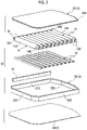
- the high-pressure container unit 10 is configured to include a case 12, a container main body 14, a manifold 16, and a lower reinforcing member 18 as a reinforcing member.
- the case 12 is a metal member formed in a substantially box shape and is configured to include a bottom portion 24, a ceiling portion 20, and a peripheral wall portion 22.
- the bottom portion 24 is formed in a substantially rectangular shape when viewed in a plan view and is configured with a flat plate member in which a thickness direction thereof is in the up-down direction.
- the ceiling portion 20 is provided on the side opposite to the bottom portion 24 with the peripheral wall portion 22 interposed therebetween and is formed in a shape corresponding to the bottom portion 24 when viewed in a plan view.
- a joining portion 20A is formed at a peripheral end portion of the ceiling portion 20, and the joining portion 20A is formed at a position one step lower than a general portion. Then, the joining portion 20A is joined to the upper end surface of the peripheral wall portion 22, whereby an opening on the upper side of the case 12 is closed.
- the peripheral wall portion 22 is provided to be erected on the bottom portion 24, thereby configuring a peripheral wall of the case 12.
- the peripheral wall portion 22 includes a front wall 22A extending in the vehicle width direction on the vehicle front side, and a right wall 22B extends from a right end portion of the front wall 22A toward the vehicle rear side.
- a left wall 22C extends from a left end portion of the front wall 22A toward the vehicle rear side, and a rear end of the right wall 22B and a rear end of the left wall 22C are connected to each other by a rear wall 22D extending in the vehicle width direction.
- each of the front wall 22A, the right wall 22B, the left wall 22C, and the rear wall 22D is formed in a closed cross-sectional shape by extrusion molding or the like. Both end portions in the vehicle width direction of the front wall 22A and both end portions in the vehicle width direction of the rear wall 22D are bent in order to prevent interference with peripheral members.
- a plurality of container main bodies 14 is arranged in the interior of the case 12, and, as an example, ten container main bodies 14 are arranged in the front-rear direction of the vehicle.
- Each of the container main bodies 14 is provided with a substantially cylindrical body portion 14A in which an axial direction thereof is in the vehicle width direction.
- the body portion 14A extends in the vehicle width direction with a constant diameter in the axial direction, and hemispherical dome portions 14B are integrally formed at both end portions in the axial direction (vehicle width direction) of the body portion 14A.
- the container main body 14 is formed mainly of an aluminum alloy.
- the container main body 14 may be formed mainly of resin.
- a cap 26 is mounted to the dome portion 14B on the right side of the vehicle in the container main body 14. Then, the cap 26 is assembled to the manifold 16.
- the manifold 16 extends in the front-rear direction of the vehicle, and a flow path communicating with an internal space of each of the container main bodies 14 is formed in the interior of the manifold 16. In this way, the internal spaces of all the container main bodies 14 communicate with each other by the manifold 16, and the ten container main bodies 14 are configured to function as a single high-pressure container.
- a valve (not shown) is mounted to the manifold 16, and a high-pressure gas filled in the interior of the container main body 14 can be replenished and supplied through the valve.
- the dome portion 14B on the left side of the vehicle in the container main body 14 is fixed to the left wall 22C of the peripheral wall portion 22 of the case 12.
- a mounting portion 14C extends from the dome portion 14B on the vehicle left side of the container main body 14 toward the left side of the vehicle, and the mounting portion 14C is mounted to a mounted portion (not shown) provided at the left wall 22C.
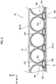
- a gap is provided between one end portion (an end portion on the vehicle right side) in the axial direction of the container main body 14 and the right wall 22B (the peripheral wall portion 22) of the case 12, and a gap is not provided between the other end portion (an end portion on the vehicle left side) in the axial direction of the container main body 14 and the left wall 22C (the peripheral wall portion 22) of the case 12. That is, the end portion on the vehicle left side of the container main body 14 is fixed to the case 12 so as not to move, and in the state of being fixed to the case 12, a slight gap is provided between the container main bodies 14 adjacent to each other, as shown in FIG. 4 .
- the lower reinforcing member 18 made of metal is provided in a space surrounded by the container main bodies 14 adjacent to each other and the bottom portion 24 of the case 12. As shown in FIG. 3 , a plurality of lower reinforcing members 18 is provided and arranged in the front-rear direction of the vehicle. Each of the lower reinforcing members 18 extends with a longitudinal direction thereof being in the vehicle width direction. In other words, the lower reinforcing member 18 extends along the axial direction of the container main body 14.
- the lower reinforcing member 18 is formed such that a cross section as viewed in the vehicle width direction has a substantially trapezoidal shape, and is configured in a closed cross-sectional shape including an upper surface portion 18A, a lower surface portion 18B, and a side surface portion 18C.
- the lower surface portion 18B is formed longer than the upper surface portion 18A in the front-rear direction of the vehicle and is superimposed on the bottom portion 24 of the case 12. Then, the lower surface portion 18B of the lower reinforcing member 18 is fixed to the bottom portion 24.
- the side surface portion 18C of the lower reinforcing member 18 is slightly curved so as to correspond to the circumferential surface of the container main body 14 and is in contact with the container main body 14.
- one end portion of the lower reinforcing member 18 is fixed to the right wall 22B configuring the peripheral wall portion 22, and the other end portion of the lower reinforcing member 18 is fixed to the left wall 22C configuring the peripheral wall portion 22.
- the plurality of container main bodies 14 is arranged in the interior of the case 12, and the lower reinforcing member 18 extends along the axial direction of the container main body 14. In this way, it is possible to reinforce the container main body 14. An external force such as a collision load input to one side in the axial direction of the container main body 14 can be transmitted to the other side in the axial direction, and thus it is possible to improve the collision resistance performance.
- the lower reinforcing member 18 is provided in the space surrounded by the container main bodies 14 adjacent to each other and the bottom portion 24. In this way, it is possible to dispose the lower reinforcing member 18 without reducing the diameter of the container main body 14. That is, since a dead space is utilized, it is not necessary to reduce the capacity of the container main body 14. As a result, it is possible to improve the collision resistance performance while securing the capacity of the container main body 14.
- the lower reinforcing member 18 extends in the vehicle width direction. In this way, at the time of a side collision, a collision load input to one side in the vehicle width direction can be effectively transmitted to the other end side in the vehicle width direction by the lower reinforcing member 18, and thus it is possible to improve the collision resistance performance at the time of the side collision.
- Both end portions in the longitudinal direction of the lower reinforcing member 18 are respectively fixed to the right wall 22B and the left wall 22C of the peripheral wall portion 22. In this way, it is possible to reliably transmit the collision load to the anti-collision side, compared to a configuration in which the length of the lower reinforcing member 18 is shorter than the length between the right wall 22B and the left wall 22C.
- a gap is provided between the container main body 14 and the right wall 22B.
- the collision load can be received by the lower reinforcing member 18. That is, the container main body 14 can be restrained from being pinched between the right wall 22B and the left wall 22C of the peripheral wall portion 22. As a result, it is possible to improve the collision resistance performance.
- a lower reinforcing member 52 is provided in a space surrounded by the container main bodies 14 adjacent to each other and the bottom portion 24 of the case 12.
- an upper reinforcing member 54 is provided in a space surrounded by the container main bodies 14 adjacent to each other and the ceiling portion 20 of the case 12.
- the lower reinforcing member 52 extends along the axial direction of the container main body 14, and in this embodiment, the lower reinforcing member 52 extends with a longitudinal direction thereof being in the vehicle width direction.
- the lower reinforcing member 52 is formed such that a cross section as viewed in the vehicle width direction has a substantially triangular shape, and is configured to include a lower surface portion 52A and a pair of side surface portions 52B.
- the lower surface portion 52A is fixed to the bottom portion 24 of the case 12 in a state of being superimposed on the bottom portion 24.
- the side surface portions 52B obliquely extend from both end portions of the lower surface portion 52A toward the I vehicle upper side, and the tips thereof are connected to form an apex of a triangle.
- the upper reinforcing member 54 extends substantially parallel to the lower reinforcing member 52 along the axial direction of the container main body 14.
- the upper reinforcing member 54 is provided at a position corresponding to the lower reinforcing member 52, and is formed such that a cross section as viewed in the vehicle width direction has a substantially triangular shape.
- the upper reinforcing member 54 is configured to include an upper surface portion 54A and a pair of side surface portions 54B, and the upper surface portion 54A is fixed to the ceiling portion 20 of the case 12 in a state of being superimposed on the ceiling portion 20.
- the side surface portions 54B obliquely extend from both end portions of the upper surface portion 54A toward the vehicle lower side, and the tips thereof are connected to form an apex of a triangle.
- the lower reinforcing member 52 and the upper reinforcing member 54 are connected up and down by a connecting member 56.
- the connecting member 56 is formed of a flat plate-like member in which a thickness direction thereof is in the front-rear direction of the vehicle, and in this embodiment, the connecting member 56 extends in the vehicle width direction together with the lower reinforcing member 52 and the upper reinforcing member 54.
- a lower end portion of the connecting member 56 is joined to an upper end portion of the lower reinforcing member 52, and an upper end portion of the connecting member 56 is joined to a lower end portion of the upper reinforcing member 54.
- each of the lower reinforcing member 52 and the upper reinforcing member 54 has one end portion fixed to the right wall 22B of the peripheral wall portion 22 of the case 12 and the other end portion fixed to the left wall 22C, similarly to the lower reinforcing member 18 of figures 1-4 (refer to FIG. 2 ).
- both the lower reinforcing member 52 and the upper reinforcing member 54 are provided, and therefore, the collision resistance performance can be further improved compared to a structure in which only one of the lower reinforcing member 52 and the upper reinforcing member 54 is provided.
- Both the space surrounded by the container main bodies 14 adjacent to each other and the bottom portion 24 and the space surrounded by the container main bodies 14 adjacent to each other and the ceiling portion 20 are dead spaces, and therefore, even in a case where the lower reinforcing member 52 and the upper reinforcing member 54 are disposed in these spaces, it is not necessary to reduce the capacity of the container main body 14.
- the lower reinforcing member 52 and the upper reinforcing member 54 are connected up and down by the connecting member 56, and therefore, in a case where a collision load is input, the collision load can be dispersed between the lower reinforcing member 52 and the upper reinforcing member 54. As a result, the collision resistance performance can be improved compared to a structure in which the connecting member 56 is not provided.
- the high pressure container units have been described above. However, of course, various aspects can be made within a scope that does not depart from the gist of this disclosure.
- the cross section of the lower reinforcing member 18 is made to be a substantially trapezoidal shape
- the cross section of the lower reinforcing member 52 is made to be a substantially triangular shape.
- the lower reinforcing member 52 of the embodiment may be formed to have a substantially trapezoidal cross section.
- the upper reinforcing member 54 may be formed to have a substantially trapezoidal cross section.
- the left end portion of the container main body 14 is fixed to the case 12.
- a configuration may be made in which the left end portion of the container main body 14 is supported by a bracket or the like provided on the bottom portion 24, so that a gap is provided between the left end portion of the container main body 14 and the case 12.
- a structure is made in which both end portions in the axial direction of the container main body 14 are separated from the peripheral wall portion 22 of the case 12, and therefore, at the time of a collision such as a side collision, before a collision load is input to the container main body 14, the collision load can be reliably received by the reinforcing member.
- the container main body is mounted on the vehicle such that the axial direction of the container main body 14 is in the vehicle width direction.
- the container main body may be mounted on the vehicle such that the axial direction of the container main body 14 is in the front-rear direction of the vehicle.
- a two-stage structure may be made in which a plurality of container main bodies 14 is arranged with the axial direction thereof being in the front-rear direction of the vehicle on the container main bodies 14 arranged with the axial direction thereof being in the vehicle width direction.
Landscapes
- Engineering & Computer Science (AREA)
- Mechanical Engineering (AREA)
- Life Sciences & Earth Sciences (AREA)
- Sustainable Development (AREA)
- Sustainable Energy (AREA)
- Chemical & Material Sciences (AREA)
- Combustion & Propulsion (AREA)
- Transportation (AREA)
- General Engineering & Computer Science (AREA)
- Cooling, Air Intake And Gas Exhaust, And Fuel Tank Arrangements In Propulsion Units (AREA)
- Filling Or Discharging Of Gas Storage Vessels (AREA)
Claims (3)
- Hochdruckbehältereinheit (10), die Folgendes umfasst:ein kastenförmiges Gehäuse (12), das an einem Fahrzeug angebracht ist und so gestaltet ist, dass es einen Bodenabschnitt (24), einen Deckenabschnitt (20) und einen Umfangswandabschnitt (22) aufweist;eine Vielzahl von Behälterhauptkörpern (14), die in einem Innenraum des Gehäuses (12) angeordnet sind und jeweils einen zylindrischen Körperabschnitt (14A) aufweisen; undVerstärkungselemente (18; 52, 54), die sich entlang einer axialen Richtung des Behälterhauptkörpers (14) erstrecken, wobei die Verstärkungselemente (18; 52, 54) in mindestens einem von einem Raum, der von den Behälterhauptkörpern (14) umgeben ist, die aneinander und an den Bodenabschnitt (24) angrenzen, und einem Raum, der von den aneinander angrenzenden Behälterhauptkörpern (14) und dem Deckenabschnitt (20) umgeben ist, vorgesehen sind.wobei die Verstärkungselemente (52, 54) Folgendes umfassen: ein unteres Verstärkungselement (52), das in einem Raum vorgesehen ist, der von den aneinander angrenzenden Behälterhauptkörpern (14) und dem Bodenabschnitt (24) umgeben ist, und ein oberes Verstärkungselement (54), das in einem Raum vorgesehen ist, der von den aneinander angrenzenden Behälterhauptkörpern (14) und dem Deckenabschnitt (20) umgeben ist,dadurch gekennzeichnet, dass es ferner ein Verbindungselement (56) umfasst, das das untere Verstärkungselement (52) und das obere Verstärkungselement (54) in einer vertikalen Richtung verbindet.
- Hochdruckbehältereinheit (10) nach Anspruch 1, wobei:ein Spalt zwischen mindestens einem Endabschnitt in der axialen Richtung des Behälterhauptkörpers (14) und dem Umfangswandabschnitt (22) des Gehäuses (12) vorgesehen ist; undbeide Endabschnitte in einer Längsrichtung der Verstärkungselemente (18; 52, 54) an dem Umfangswandabschnitt (22) befestigt sind.
- Hochdruckbehältereinheit (10) nach einem der Ansprüche 1 und 2, wobei sich die Verstärkungselemente (18; 52, 54) in einem Zustand, in dem sie am Fahrzeug montiert sind, in Richtung der Fahrzeugbreite erstrecken.
Applications Claiming Priority (1)
| Application Number | Priority Date | Filing Date | Title |
|---|---|---|---|
| JP2018231955A JP7215128B2 (ja) | 2018-12-11 | 2018-12-11 | 高圧容器ユニット |
Publications (2)
| Publication Number | Publication Date |
|---|---|
| EP3667151A1 EP3667151A1 (de) | 2020-06-17 |
| EP3667151B1 true EP3667151B1 (de) | 2022-12-14 |
Family
ID=68610014
Family Applications (1)
| Application Number | Title | Priority Date | Filing Date |
|---|---|---|---|
| EP19209773.1A Active EP3667151B1 (de) | 2018-12-11 | 2019-11-18 | Hochdruckbehältereinheit |
Country Status (4)
| Country | Link |
|---|---|
| US (1) | US11447005B2 (de) |
| EP (1) | EP3667151B1 (de) |
| JP (1) | JP7215128B2 (de) |
| CN (1) | CN111306437B (de) |
Families Citing this family (8)
| Publication number | Priority date | Publication date | Assignee | Title |
|---|---|---|---|---|
| DE102021102694A1 (de) * | 2021-02-05 | 2022-08-11 | Bayerische Motoren Werke Aktiengesellschaft | Druckbehälterbaugruppe und Kraftfahrzeug |
| DE102021106038A1 (de) | 2021-03-12 | 2021-05-12 | Bayerische Motoren Werke Aktiengesellschaft | Druckbehältersystem mit einer Druckbehälterbaugruppe |
| NO20210349A1 (en) * | 2021-03-18 | 2022-09-19 | Deep Purple As | Submersible system for storing tanks and method of storing tanks on a seabed. |
| US11703185B2 (en) * | 2021-03-22 | 2023-07-18 | Ezng Solutions, Llc | Apparatus, systems, and methods for storing and transporting compressed fluids |
| KR102948443B1 (ko) * | 2021-07-14 | 2026-04-06 | 현대자동차주식회사 | 차량용 플로어구조 |
| US20230235859A1 (en) * | 2022-01-25 | 2023-07-27 | HyDaaS Inc. | Mobile liquid hydrogen refueling station |
| DE102022102964A1 (de) | 2022-02-09 | 2023-08-10 | Bayerische Motoren Werke Aktiengesellschaft | Kraftfahrzeug und Druckbehältersystem mit nachgiebiger Unterbodenverkleidung |
| DE102022132218A1 (de) | 2022-12-05 | 2024-06-06 | Bayerische Motoren Werke Aktiengesellschaft | Druckbehältersystem mit einer Druckbehälterbaugruppe |
Family Cites Families (21)
| Publication number | Priority date | Publication date | Assignee | Title |
|---|---|---|---|---|
| US4522159A (en) * | 1983-04-13 | 1985-06-11 | Michigan Consolidated Gas Co. | Gaseous hydrocarbon fuel storage system and power plant for vehicles and associated refueling apparatus |
| US5154556A (en) * | 1990-08-30 | 1992-10-13 | Camco International Inc. | Retention device for metal cylindrical containers |
| US5658013A (en) * | 1995-09-20 | 1997-08-19 | The Babcock & Wilcox Company | Fuel tank for vehicles for holding and dispensing both a liquid and gaseous fuel therein |
| US5673939A (en) * | 1995-09-20 | 1997-10-07 | The Babcock & Wilcox Company | Fuel tank for storing and dispensing hydrogen and oxygen gas to a fuel cell |
| MY125147A (en) * | 1998-10-27 | 2006-07-31 | Univ Johns Hopkins | Compressed gas manifold |
| JP2004026088A (ja) | 2002-06-27 | 2004-01-29 | Nissan Motor Co Ltd | 燃料タンクの取付構造 |
| US7189040B2 (en) * | 2004-02-03 | 2007-03-13 | Dynetek Industries Ltd. | Composite impact assembly |
| US7624753B2 (en) * | 2004-08-10 | 2009-12-01 | Gm Global Technology Operations, Inc. | Container for gas storage tanks in a vehicle |
| US7270209B2 (en) * | 2004-08-10 | 2007-09-18 | General Motors Corporation | Modular fuel storage system for a vehicle |
| JP4825583B2 (ja) | 2005-06-28 | 2011-11-30 | 本田技研工業株式会社 | 車体構造 |
| JP2008049961A (ja) | 2006-08-28 | 2008-03-06 | Toyota Motor Corp | タンクの搭載構造 |
| DE102010018093A1 (de) * | 2010-04-24 | 2011-10-27 | Gm Global Technology Operations Llc (N.D.Ges.D. Staates Delaware) | Tankmodul für ein Kraftfahrzeug |
| DE102010045705A1 (de) * | 2010-09-16 | 2011-07-07 | Daimler AG, 70327 | Drucktank in einem Kraftfahrzeug mit einem Zugelement |
| US9174531B2 (en) * | 2013-06-19 | 2015-11-03 | Fca Us Llc | Modular fuel storage system |
| CN204567277U (zh) * | 2015-03-09 | 2015-08-19 | 南京金龙客车制造有限公司 | 一种车用cng气瓶的安装组件 |
| KR101745269B1 (ko) * | 2016-07-01 | 2017-06-09 | 현대자동차주식회사 | 압력용기 고정장치 및 그 제조방법 |
| CN106240352A (zh) * | 2016-08-28 | 2016-12-21 | 安徽安凯汽车股份有限公司 | 一种底置气瓶安装结构 |
| US10422477B2 (en) * | 2017-04-07 | 2019-09-24 | United Technologies Corporation | Composite vessel assembly and method of manufacture |
| US10717356B2 (en) | 2017-08-09 | 2020-07-21 | Toyota Jidosha Kabushiki Kaisha | High pressure canister unit and fuel cell vehicle |
| JP7067241B2 (ja) | 2017-08-09 | 2022-05-16 | トヨタ自動車株式会社 | 高圧容器ユニット及び燃料電池車両 |
| CN207772885U (zh) * | 2017-11-29 | 2018-08-28 | 中材高新成都能源技术有限公司 | 一种侧置式天然气气瓶支架总成 |
-
2018
- 2018-12-11 JP JP2018231955A patent/JP7215128B2/ja active Active
-
2019
- 2019-11-18 EP EP19209773.1A patent/EP3667151B1/de active Active
- 2019-11-21 CN CN201911149822.5A patent/CN111306437B/zh active Active
- 2019-11-26 US US16/695,188 patent/US11447005B2/en active Active
Also Published As
| Publication number | Publication date |
|---|---|
| US11447005B2 (en) | 2022-09-20 |
| CN111306437B (zh) | 2024-04-30 |
| CN111306437A (zh) | 2020-06-19 |
| EP3667151A1 (de) | 2020-06-17 |
| US20200180428A1 (en) | 2020-06-11 |
| JP7215128B2 (ja) | 2023-01-31 |
| JP2020093630A (ja) | 2020-06-18 |
Similar Documents
| Publication | Publication Date | Title |
|---|---|---|
| EP3667151B1 (de) | Hochdruckbehältereinheit | |
| US10399607B2 (en) | Vehicle floor structure | |
| US9440678B2 (en) | Vehicle frame structure | |
| US11485223B2 (en) | High-pressure vessel mounting structure | |
| US9764705B2 (en) | Vehicle connecting member and vehicle front section structure | |
| US20160332588A1 (en) | Vehicle front portion structure | |
| CN104349970B (zh) | 车身构造 | |
| EP2915703A1 (de) | Vorderaufbau eines Fahrzeugaufbaus | |
| US20180148106A1 (en) | Vehicle body lower portion structure | |
| EP3064389A1 (de) | Batterieeinheitmontagestruktur | |
| US9944326B2 (en) | Vehicle body side portion structure | |
| EP2889187A2 (de) | Fahrzeugkarosseriestoßabsorptionsstruktur | |
| US20170050598A1 (en) | Vehicle frame structure | |
| US9260136B2 (en) | Vehicle lower portion structure | |
| EP3007923B1 (de) | Kraftstoffbehälter | |
| CN112455546A (zh) | 车辆用副车架 | |
| JP6835511B2 (ja) | 樹脂燃料タンク | |
| CN111186495A (zh) | 车辆前部结构 | |
| US10589622B2 (en) | Fuel tank having a sub-tank provided on the inside of the fuel tank body | |
| JP4475088B2 (ja) | タンク支持構造 | |
| JP2014019307A (ja) | 車体前部構造 | |
| JP2011189806A (ja) | インパネリインフォースメント | |
| CN108725183B (zh) | 车辆用燃料配管保护结构 | |
| JP6123663B2 (ja) | 燃料タンク | |
| CN105365890A (zh) | 车辆框架结构 |
Legal Events
| Date | Code | Title | Description |
|---|---|---|---|
| PUAI | Public reference made under article 153(3) epc to a published international application that has entered the european phase |
Free format text: ORIGINAL CODE: 0009012 |
|
| STAA | Information on the status of an ep patent application or granted ep patent |
Free format text: STATUS: REQUEST FOR EXAMINATION WAS MADE |
|
| 17P | Request for examination filed |
Effective date: 20191118 |
|
| AK | Designated contracting states |
Kind code of ref document: A1 Designated state(s): AL AT BE BG CH CY CZ DE DK EE ES FI FR GB GR HR HU IE IS IT LI LT LU LV MC MK MT NL NO PL PT RO RS SE SI SK SM TR |
|
| AX | Request for extension of the european patent |
Extension state: BA ME |
|
| GRAP | Despatch of communication of intention to grant a patent |
Free format text: ORIGINAL CODE: EPIDOSNIGR1 |
|
| STAA | Information on the status of an ep patent application or granted ep patent |
Free format text: STATUS: GRANT OF PATENT IS INTENDED |
|
| INTG | Intention to grant announced |
Effective date: 20220921 |
|
| GRAS | Grant fee paid |
Free format text: ORIGINAL CODE: EPIDOSNIGR3 |
|
| GRAA | (expected) grant |
Free format text: ORIGINAL CODE: 0009210 |
|
| STAA | Information on the status of an ep patent application or granted ep patent |
Free format text: STATUS: THE PATENT HAS BEEN GRANTED |
|
| AK | Designated contracting states |
Kind code of ref document: B1 Designated state(s): AL AT BE BG CH CY CZ DE DK EE ES FI FR GB GR HR HU IE IS IT LI LT LU LV MC MK MT NL NO PL PT RO RS SE SI SK SM TR |
|
| REG | Reference to a national code |
Ref country code: GB Ref legal event code: FG4D |
|
| REG | Reference to a national code |
Ref country code: CH Ref legal event code: EP |
|
| REG | Reference to a national code |
Ref country code: DE Ref legal event code: R096 Ref document number: 602019023116 Country of ref document: DE |
|
| REG | Reference to a national code |
Ref country code: IE Ref legal event code: FG4D |
|
| REG | Reference to a national code |
Ref country code: AT Ref legal event code: REF Ref document number: 1537871 Country of ref document: AT Kind code of ref document: T Effective date: 20230115 |
|
| REG | Reference to a national code |
Ref country code: LT Ref legal event code: MG9D |
|
| REG | Reference to a national code |
Ref country code: NL Ref legal event code: MP Effective date: 20221214 |
|
| PG25 | Lapsed in a contracting state [announced via postgrant information from national office to epo] |
Ref country code: SE Free format text: LAPSE BECAUSE OF FAILURE TO SUBMIT A TRANSLATION OF THE DESCRIPTION OR TO PAY THE FEE WITHIN THE PRESCRIBED TIME-LIMIT Effective date: 20221214 Ref country code: NO Free format text: LAPSE BECAUSE OF FAILURE TO SUBMIT A TRANSLATION OF THE DESCRIPTION OR TO PAY THE FEE WITHIN THE PRESCRIBED TIME-LIMIT Effective date: 20230314 Ref country code: LT Free format text: LAPSE BECAUSE OF FAILURE TO SUBMIT A TRANSLATION OF THE DESCRIPTION OR TO PAY THE FEE WITHIN THE PRESCRIBED TIME-LIMIT Effective date: 20221214 Ref country code: FI Free format text: LAPSE BECAUSE OF FAILURE TO SUBMIT A TRANSLATION OF THE DESCRIPTION OR TO PAY THE FEE WITHIN THE PRESCRIBED TIME-LIMIT Effective date: 20221214 |
|
| REG | Reference to a national code |
Ref country code: AT Ref legal event code: MK05 Ref document number: 1537871 Country of ref document: AT Kind code of ref document: T Effective date: 20221214 |
|
| PG25 | Lapsed in a contracting state [announced via postgrant information from national office to epo] |
Ref country code: RS Free format text: LAPSE BECAUSE OF FAILURE TO SUBMIT A TRANSLATION OF THE DESCRIPTION OR TO PAY THE FEE WITHIN THE PRESCRIBED TIME-LIMIT Effective date: 20221214 Ref country code: LV Free format text: LAPSE BECAUSE OF FAILURE TO SUBMIT A TRANSLATION OF THE DESCRIPTION OR TO PAY THE FEE WITHIN THE PRESCRIBED TIME-LIMIT Effective date: 20221214 Ref country code: HR Free format text: LAPSE BECAUSE OF FAILURE TO SUBMIT A TRANSLATION OF THE DESCRIPTION OR TO PAY THE FEE WITHIN THE PRESCRIBED TIME-LIMIT Effective date: 20221214 Ref country code: GR Free format text: LAPSE BECAUSE OF FAILURE TO SUBMIT A TRANSLATION OF THE DESCRIPTION OR TO PAY THE FEE WITHIN THE PRESCRIBED TIME-LIMIT Effective date: 20230315 |
|
| REG | Reference to a national code |
Ref country code: DE Ref legal event code: R084 Ref document number: 602019023116 Country of ref document: DE |
|
| PG25 | Lapsed in a contracting state [announced via postgrant information from national office to epo] |
Ref country code: NL Free format text: LAPSE BECAUSE OF FAILURE TO SUBMIT A TRANSLATION OF THE DESCRIPTION OR TO PAY THE FEE WITHIN THE PRESCRIBED TIME-LIMIT Effective date: 20221214 |
|
| PG25 | Lapsed in a contracting state [announced via postgrant information from national office to epo] |
Ref country code: SM Free format text: LAPSE BECAUSE OF FAILURE TO SUBMIT A TRANSLATION OF THE DESCRIPTION OR TO PAY THE FEE WITHIN THE PRESCRIBED TIME-LIMIT Effective date: 20221214 Ref country code: RO Free format text: LAPSE BECAUSE OF FAILURE TO SUBMIT A TRANSLATION OF THE DESCRIPTION OR TO PAY THE FEE WITHIN THE PRESCRIBED TIME-LIMIT Effective date: 20221214 Ref country code: PT Free format text: LAPSE BECAUSE OF FAILURE TO SUBMIT A TRANSLATION OF THE DESCRIPTION OR TO PAY THE FEE WITHIN THE PRESCRIBED TIME-LIMIT Effective date: 20230414 Ref country code: ES Free format text: LAPSE BECAUSE OF FAILURE TO SUBMIT A TRANSLATION OF THE DESCRIPTION OR TO PAY THE FEE WITHIN THE PRESCRIBED TIME-LIMIT Effective date: 20221214 Ref country code: EE Free format text: LAPSE BECAUSE OF FAILURE TO SUBMIT A TRANSLATION OF THE DESCRIPTION OR TO PAY THE FEE WITHIN THE PRESCRIBED TIME-LIMIT Effective date: 20221214 Ref country code: CZ Free format text: LAPSE BECAUSE OF FAILURE TO SUBMIT A TRANSLATION OF THE DESCRIPTION OR TO PAY THE FEE WITHIN THE PRESCRIBED TIME-LIMIT Effective date: 20221214 Ref country code: AT Free format text: LAPSE BECAUSE OF FAILURE TO SUBMIT A TRANSLATION OF THE DESCRIPTION OR TO PAY THE FEE WITHIN THE PRESCRIBED TIME-LIMIT Effective date: 20221214 |
|
| PG25 | Lapsed in a contracting state [announced via postgrant information from national office to epo] |
Ref country code: SK Free format text: LAPSE BECAUSE OF FAILURE TO SUBMIT A TRANSLATION OF THE DESCRIPTION OR TO PAY THE FEE WITHIN THE PRESCRIBED TIME-LIMIT Effective date: 20221214 Ref country code: PL Free format text: LAPSE BECAUSE OF FAILURE TO SUBMIT A TRANSLATION OF THE DESCRIPTION OR TO PAY THE FEE WITHIN THE PRESCRIBED TIME-LIMIT Effective date: 20221214 Ref country code: IS Free format text: LAPSE BECAUSE OF FAILURE TO SUBMIT A TRANSLATION OF THE DESCRIPTION OR TO PAY THE FEE WITHIN THE PRESCRIBED TIME-LIMIT Effective date: 20230414 Ref country code: AL Free format text: LAPSE BECAUSE OF FAILURE TO SUBMIT A TRANSLATION OF THE DESCRIPTION OR TO PAY THE FEE WITHIN THE PRESCRIBED TIME-LIMIT Effective date: 20221214 |
|
| REG | Reference to a national code |
Ref country code: DE Ref legal event code: R097 Ref document number: 602019023116 Country of ref document: DE |
|
| PLBE | No opposition filed within time limit |
Free format text: ORIGINAL CODE: 0009261 |
|
| STAA | Information on the status of an ep patent application or granted ep patent |
Free format text: STATUS: NO OPPOSITION FILED WITHIN TIME LIMIT |
|
| PG25 | Lapsed in a contracting state [announced via postgrant information from national office to epo] |
Ref country code: DK Free format text: LAPSE BECAUSE OF FAILURE TO SUBMIT A TRANSLATION OF THE DESCRIPTION OR TO PAY THE FEE WITHIN THE PRESCRIBED TIME-LIMIT Effective date: 20221214 |
|
| 26N | No opposition filed |
Effective date: 20230915 |
|
| PG25 | Lapsed in a contracting state [announced via postgrant information from national office to epo] |
Ref country code: SI Free format text: LAPSE BECAUSE OF FAILURE TO SUBMIT A TRANSLATION OF THE DESCRIPTION OR TO PAY THE FEE WITHIN THE PRESCRIBED TIME-LIMIT Effective date: 20221214 |
|
| PG25 | Lapsed in a contracting state [announced via postgrant information from national office to epo] |
Ref country code: IT Free format text: LAPSE BECAUSE OF FAILURE TO SUBMIT A TRANSLATION OF THE DESCRIPTION OR TO PAY THE FEE WITHIN THE PRESCRIBED TIME-LIMIT Effective date: 20221214 |
|
| REG | Reference to a national code |
Ref country code: DE Ref legal event code: R119 Ref document number: 602019023116 Country of ref document: DE |
|
| REG | Reference to a national code |
Ref country code: CH Ref legal event code: PL |
|
| PG25 | Lapsed in a contracting state [announced via postgrant information from national office to epo] |
Ref country code: MC Free format text: LAPSE BECAUSE OF FAILURE TO SUBMIT A TRANSLATION OF THE DESCRIPTION OR TO PAY THE FEE WITHIN THE PRESCRIBED TIME-LIMIT Effective date: 20221214 |
|
| PG25 | Lapsed in a contracting state [announced via postgrant information from national office to epo] |
Ref country code: LU Free format text: LAPSE BECAUSE OF NON-PAYMENT OF DUE FEES Effective date: 20231118 |
|
| PG25 | Lapsed in a contracting state [announced via postgrant information from national office to epo] |
Ref country code: CH Free format text: LAPSE BECAUSE OF NON-PAYMENT OF DUE FEES Effective date: 20231130 |
|
| GBPC | Gb: european patent ceased through non-payment of renewal fee |
Effective date: 20231118 |
|
| PG25 | Lapsed in a contracting state [announced via postgrant information from national office to epo] |
Ref country code: MC Free format text: LAPSE BECAUSE OF FAILURE TO SUBMIT A TRANSLATION OF THE DESCRIPTION OR TO PAY THE FEE WITHIN THE PRESCRIBED TIME-LIMIT Effective date: 20221214 Ref country code: LU Free format text: LAPSE BECAUSE OF NON-PAYMENT OF DUE FEES Effective date: 20231118 Ref country code: CH Free format text: LAPSE BECAUSE OF NON-PAYMENT OF DUE FEES Effective date: 20231130 |
|
| REG | Reference to a national code |
Ref country code: BE Ref legal event code: MM Effective date: 20231130 |
|
| REG | Reference to a national code |
Ref country code: IE Ref legal event code: MM4A |
|
| PG25 | Lapsed in a contracting state [announced via postgrant information from national office to epo] |
Ref country code: DE Free format text: LAPSE BECAUSE OF NON-PAYMENT OF DUE FEES Effective date: 20240601 Ref country code: IE Free format text: LAPSE BECAUSE OF NON-PAYMENT OF DUE FEES Effective date: 20231118 |
|
| PG25 | Lapsed in a contracting state [announced via postgrant information from national office to epo] |
Ref country code: GB Free format text: LAPSE BECAUSE OF NON-PAYMENT OF DUE FEES Effective date: 20231118 |
|
| PG25 | Lapsed in a contracting state [announced via postgrant information from national office to epo] |
Ref country code: BE Free format text: LAPSE BECAUSE OF NON-PAYMENT OF DUE FEES Effective date: 20231130 |
|
| PG25 | Lapsed in a contracting state [announced via postgrant information from national office to epo] |
Ref country code: FR Free format text: LAPSE BECAUSE OF NON-PAYMENT OF DUE FEES Effective date: 20231130 |
|
| PG25 | Lapsed in a contracting state [announced via postgrant information from national office to epo] |
Ref country code: IE Free format text: LAPSE BECAUSE OF NON-PAYMENT OF DUE FEES Effective date: 20231118 Ref country code: GB Free format text: LAPSE BECAUSE OF NON-PAYMENT OF DUE FEES Effective date: 20231118 Ref country code: FR Free format text: LAPSE BECAUSE OF NON-PAYMENT OF DUE FEES Effective date: 20231130 Ref country code: DE Free format text: LAPSE BECAUSE OF NON-PAYMENT OF DUE FEES Effective date: 20240601 Ref country code: BE Free format text: LAPSE BECAUSE OF NON-PAYMENT OF DUE FEES Effective date: 20231130 |
|
| PG25 | Lapsed in a contracting state [announced via postgrant information from national office to epo] |
Ref country code: BG Free format text: LAPSE BECAUSE OF FAILURE TO SUBMIT A TRANSLATION OF THE DESCRIPTION OR TO PAY THE FEE WITHIN THE PRESCRIBED TIME-LIMIT Effective date: 20221214 |
|
| PG25 | Lapsed in a contracting state [announced via postgrant information from national office to epo] |
Ref country code: BG Free format text: LAPSE BECAUSE OF FAILURE TO SUBMIT A TRANSLATION OF THE DESCRIPTION OR TO PAY THE FEE WITHIN THE PRESCRIBED TIME-LIMIT Effective date: 20221214 |
|
| PG25 | Lapsed in a contracting state [announced via postgrant information from national office to epo] |
Ref country code: CY Free format text: LAPSE BECAUSE OF FAILURE TO SUBMIT A TRANSLATION OF THE DESCRIPTION OR TO PAY THE FEE WITHIN THE PRESCRIBED TIME-LIMIT; INVALID AB INITIO Effective date: 20191118 |
|
| PG25 | Lapsed in a contracting state [announced via postgrant information from national office to epo] |
Ref country code: HU Free format text: LAPSE BECAUSE OF FAILURE TO SUBMIT A TRANSLATION OF THE DESCRIPTION OR TO PAY THE FEE WITHIN THE PRESCRIBED TIME-LIMIT; INVALID AB INITIO Effective date: 20191118 |
|
| PG25 | Lapsed in a contracting state [announced via postgrant information from national office to epo] |
Ref country code: TR Free format text: LAPSE BECAUSE OF FAILURE TO SUBMIT A TRANSLATION OF THE DESCRIPTION OR TO PAY THE FEE WITHIN THE PRESCRIBED TIME-LIMIT Effective date: 20221214 |