EP3667041B1 - Gasmotor mit hilfskammer - Google Patents
Gasmotor mit hilfskammer Download PDFInfo
- Publication number
- EP3667041B1 EP3667041B1 EP18861842.5A EP18861842A EP3667041B1 EP 3667041 B1 EP3667041 B1 EP 3667041B1 EP 18861842 A EP18861842 A EP 18861842A EP 3667041 B1 EP3667041 B1 EP 3667041B1
- Authority
- EP
- European Patent Office
- Prior art keywords
- chamber
- precombustion
- tip portion
- thin region
- tip
- Prior art date
- Legal status (The legal status is an assumption and is not a legal conclusion. Google has not performed a legal analysis and makes no representation as to the accuracy of the status listed.)
- Not-in-force
Links
Images


Classifications
-
- F—MECHANICAL ENGINEERING; LIGHTING; HEATING; WEAPONS; BLASTING
- F02—COMBUSTION ENGINES; HOT-GAS OR COMBUSTION-PRODUCT ENGINE PLANTS
- F02B—INTERNAL-COMBUSTION PISTON ENGINES; COMBUSTION ENGINES IN GENERAL
- F02B19/00—Engines characterised by precombustion chambers
- F02B19/16—Chamber shapes or constructions not specific to sub-groups F02B19/02 - F02B19/10
- F02B19/18—Transfer passages between chamber and cylinder
-
- F—MECHANICAL ENGINEERING; LIGHTING; HEATING; WEAPONS; BLASTING
- F02—COMBUSTION ENGINES; HOT-GAS OR COMBUSTION-PRODUCT ENGINE PLANTS
- F02B—INTERNAL-COMBUSTION PISTON ENGINES; COMBUSTION ENGINES IN GENERAL
- F02B19/00—Engines characterised by precombustion chambers
- F02B19/10—Engines characterised by precombustion chambers with fuel introduced partly into pre-combustion chamber, and partly into cylinder
- F02B19/1004—Engines characterised by precombustion chambers with fuel introduced partly into pre-combustion chamber, and partly into cylinder details of combustion chamber, e.g. mounting arrangements
- F02B19/1014—Engines characterised by precombustion chambers with fuel introduced partly into pre-combustion chamber, and partly into cylinder details of combustion chamber, e.g. mounting arrangements design parameters, e.g. volume, torch passage cross sectional area, length, orientation, or the like
-
- F—MECHANICAL ENGINEERING; LIGHTING; HEATING; WEAPONS; BLASTING
- F02—COMBUSTION ENGINES; HOT-GAS OR COMBUSTION-PRODUCT ENGINE PLANTS
- F02B—INTERNAL-COMBUSTION PISTON ENGINES; COMBUSTION ENGINES IN GENERAL
- F02B19/00—Engines characterised by precombustion chambers
- F02B19/16—Chamber shapes or constructions not specific to sub-groups F02B19/02 - F02B19/10
-
- F—MECHANICAL ENGINEERING; LIGHTING; HEATING; WEAPONS; BLASTING
- F02—COMBUSTION ENGINES; HOT-GAS OR COMBUSTION-PRODUCT ENGINE PLANTS
- F02B—INTERNAL-COMBUSTION PISTON ENGINES; COMBUSTION ENGINES IN GENERAL
- F02B19/00—Engines characterised by precombustion chambers
- F02B19/12—Engines characterised by precombustion chambers with positive ignition
-
- F—MECHANICAL ENGINEERING; LIGHTING; HEATING; WEAPONS; BLASTING
- F02—COMBUSTION ENGINES; HOT-GAS OR COMBUSTION-PRODUCT ENGINE PLANTS
- F02B—INTERNAL-COMBUSTION PISTON ENGINES; COMBUSTION ENGINES IN GENERAL
- F02B43/00—Engines characterised by operating on gaseous fuels; Plants including such engines
-
- F—MECHANICAL ENGINEERING; LIGHTING; HEATING; WEAPONS; BLASTING
- F02—COMBUSTION ENGINES; HOT-GAS OR COMBUSTION-PRODUCT ENGINE PLANTS
- F02M—SUPPLYING COMBUSTION ENGINES IN GENERAL WITH COMBUSTIBLE MIXTURES OR CONSTITUENTS THEREOF
- F02M21/00—Apparatus for supplying engines with non-liquid fuels, e.g. gaseous fuels stored in liquid form
- F02M21/02—Apparatus for supplying engines with non-liquid fuels, e.g. gaseous fuels stored in liquid form for gaseous fuels
- F02M21/0218—Details on the gaseous fuel supply system, e.g. tanks, valves, pipes, pumps, rails, injectors or mixers
- F02M21/0248—Injectors
- F02M21/0281—Adapters, sockets or the like to mount injection valves onto engines; Fuel guiding passages between injectors and the air intake system or the combustion chamber
-
- Y—GENERAL TAGGING OF NEW TECHNOLOGICAL DEVELOPMENTS; GENERAL TAGGING OF CROSS-SECTIONAL TECHNOLOGIES SPANNING OVER SEVERAL SECTIONS OF THE IPC; TECHNICAL SUBJECTS COVERED BY FORMER USPC CROSS-REFERENCE ART COLLECTIONS [XRACs] AND DIGESTS
- Y02—TECHNOLOGIES OR APPLICATIONS FOR MITIGATION OR ADAPTATION AGAINST CLIMATE CHANGE
- Y02T—CLIMATE CHANGE MITIGATION TECHNOLOGIES RELATED TO TRANSPORTATION
- Y02T10/00—Road transport of goods or passengers
- Y02T10/10—Internal combustion engine [ICE] based vehicles
- Y02T10/12—Improving ICE efficiencies
Definitions
- the present disclosure relates to a precombustion chamber gas engine for combusting an air-fuel mixture in a main combustion chamber by injecting a plurality of combustion flames generated in a precombustion chamber via a plurality of nozzle holes to the main combustion chamber.
- a precombustion chamber gas engine including a main combustion chamber (main chamber) defined between a piston and a cylinder head and a precombustion chamber (auxiliary chamber) communicating with the main combustion chamber via a plurality of nozzle holes is known (for example, Patent Document 1).
- the precombustion chamber gas engine ignites an air-fuel mixture in the precombustion chamber by an ignition device such as an ignition plug, and jets combustion flames generated by the ignition via each of the nozzle holes disposed at the tip of the precombustion chamber, by which a lean premixed gas in the main combustion chamber is combusted.
- Patent Document 1 discloses that the inner wall of the precombustion chamber expands with increasing (raising) temperature of the inner wall to about 1000°C, and the expanded inner wall contracts with decreasing temperature, and that the repeated expansion and contraction of the inner wall of the precombustion chamber causes heat fatigue, which may cause a crack in the inner wall. Further, JP5357926B discloses that the crack often occurs in the vicinity of the precombustion-chamber-side opening edge of the nozzle hole.
- the precombustion-chamber-side opening edge of the nozzle hole is formed with a curved surface having a certain curvature radius to reduce the temperature difference between the opening edge and the surrounding portion.
- EP 1 777 385 A2 US 5,950,593 , EP 2 700 796 A1 and WO 91/12418 A1 disclose precombustion chamber gas engines with the pre-characterizing features of claims 1 and 2.
- JP5357926B the occurrence of crack at the precombustion-chamber-side opening edge is suppressed compared to when the precombustion-chamber-side opening edge is not formed with a curved surface, but the effect obtained by forming the curved surface is limited, and a further measure is necessary to further suppress the occurrence of crack.
- an object of at least one embodiment of the present invention is to provide a precombustion chamber gas engine that can reduce thermal stress generated around nozzle holes and suppress the occurrence of crack around the nozzle holes.
- a precombustion chamber gas engine comprises: a main-chamber forming portion forming a main combustion chamber; and a precombustion-chamber forming portion forming a precombustion chamber communicating with the main combustion chamber via a plurality of nozzle holes.
- the precombustion-chamber forming portion includes a cylindrical portion extending along an extension direction of a precombustion chamber central axis of the precombustion-chamber forming portion, and a tip portion closing a main-combustion-chamber-side end of the cylindrical portion and having the nozzle holes.
- the tip portion includes a thin region having a thickness T satisfying T ⁇ L where L is a length of each nozzle hole.
- the thin region includes a plurality of recesses formed in a region including a portion of the tip portion between each of a pair of nozzle holes adjacent each other in a circumferential direction of the tip portion; wherein each recess is shaped into a slit extending from an internal bottom surface or from an external tip surface of the tip portion in the extension direction of the precombustion-chamber central axis.
- the tip portion of the precombustion-chamber forming portion has a thin region having a thickness T satisfying T ⁇ L, where L is the length of the nozzle hole. Since the tip portion has a plurality of nozzle holes, the thin region is formed around the nozzle holes. When such a thin region is formed around the nozzle holes of the tip portion, which are largely affected by heat of the combustion flame, it is possible to reduce the heat capacity and stiffness around the nozzle holes, and it is possible to flatten the temperature distribution (temperature difference) around the nozzle holes at temperature rise.
- Reducing the heat capacity and stiffness around the nozzle holes facilitates thermal deformation (thermal expansion and thermal contraction) around the nozzle holes, thus reducing thermal strain around the nozzle holes and thermal stress generated due to confinement of the thermal strain. Further, flattening the temperature distribution around the nozzle holes at temperature rise suppresses non-uniform thermal deformation around the nozzle holes, thus reducing thermal strain around the nozzle holes and thermal stress generated due to confinement of the thermal strain. Consequently, it is possible to suppress the occurrence of crack around the nozzle holes due to heat fatigue.
- a precombustion chamber gas engine comprises: a main-chamber forming portion forming a main combustion chamber; and a precombustion-chamber forming portion forming a precombustion chamber communicating with the main combustion chamber via a plurality of nozzle holes.
- the precombustion-chamber forming portion includes a cylindrical portion extending along an extension direction of a precombustion chamber central axis of the precombustion-chamber forming portion, and a tip portion closing a main-combustion-chamber-side end of the cylindrical portion and having the nozzle holes.
- the tip portion is located on a main combustion chamber side of a reference plane that extends in a direction perpendicular to the precombustion chamber central axis at a position away from an upper edge of a precombustion-chamber-side opening of each nozzle hole by a length predetermined times a diameter of each nozzle hole in a direction opposite to the main combustion chamber along the extension direction of the precombustion chamber central axis.
- the tip portion includes a thin region having a thickness T satisfying T ⁇ T0 where T0 is a thickness of the precombustion-chamber forming portion at the reference plane.
- the thin region includes a plurality of recesses formed in a region including a portion of the tip portion between each of a pair of nozzle holes adjacent each other in a circumferential direction of the tip portion; wherein each recess is shaped into a slit extending from an internal bottom surface or from an external tip surface of the tip portion in the extension direction of the precombustion-chamber central axis.
- the tip portion of the precombustion-chamber forming portion is located on the main combustion chamber side of the reference plane that extends in a direction perpendicular to the precombustion chamber central axis at a position away from the upper edge of the precombustion-chamber-side opening of each nozzle hole by a length predetermined times, e.g., three times, the diameter of each nozzle hole in a direction opposite to the main combustion chamber along the extension direction of the precombustion chamber central axis.
- the tip portion has a thin region having a thickness T satisfying T ⁇ T0, where T0 is the thickness of the precombustion-chamber forming portion at the reference plane.
- the thickness of the thin region is less than that at the reference plane which is less affected by the combustion flame.
- a thin region is formed around the nozzle holes of the tip portion, which are largely affected by heat of the combustion flame, it is possible to reduce the heat capacity and stiffness around the nozzle holes, and it is possible to flatten the temperature distribution (temperature difference) around the nozzle holes at temperature rise. Reducing the heat capacity and stiffness around the nozzle holes facilitates thermal deformation (thermal expansion and thermal contraction) around the nozzle holes, thus reducing thermal strain around the nozzle holes and thermal stress generated due to confinement of the thermal strain.
- the thin region includes a tip of the tip portion.
- the thin region includes the tip of the tip portion, the thickness of the tip of the tip portion is reduced compared to when the thin region is not present in the tip of the tip portion.
- the heat capacity and stiffness around the nozzle holes are reduced, and the temperature distribution around the nozzle holes at temperature rise is flattened. As a result, it is possible to suppress the occurrence of crack around the nozzle holes due to heat fatigue.
- the thin region includes at least a part of a peripheral edge of a main-combustion-side opening of each nozzle hole in the tip portion.
- the thin region includes at least a part of the peripheral edge of the main-combustion-chamber-side opening of the nozzle hole in the tip portion, the thickness around the nozzle holes is reduced.
- the heat capacity and stiffness around the nozzle holes are reduced, and the temperature distribution around the nozzle holes at temperature rise is flattened. As a result, it is possible to suppress the occurrence of crack around the nozzle holes due to heat fatigue.
- the thin region includes a portion of the tip portion between a pair of nozzle holes adjacent each other in a circumferential direction of the tip portion.
- the thin region includes a portion of the tip portion between a pair of nozzle holes adjacent in the circumferential direction of the tip portion, the thickness of the portion between the pair of circumferentially adjacent nozzle holes is reduced.
- the heat capacity and stiffness around the pair of nozzle holes are reduced, and the temperature distribution around the pair of nozzle holes at temperature rise is flattened. As a result, it is possible to suppress the occurrence of crack around the nozzle holes due to heat fatigue.
- the thin region includes at least one outer recess formed in an outer peripheral surface of the tip portion facing the main combustion chamber.
- the thin region includes at least one outer recess formed in an outer peripheral surface of the tip portion facing the main combustion chamber.
- the thin region is defined by the at least one outer recess formed in the outer peripheral surface of the tip portion, it is possible to reduce thermal strain around the main-combustion-chamber-side openings of the nozzle holes and thermal stress generated due to confinement of the thermal strain.
- the thin region includes at least one inner recess formed in an inner peripheral surface of the tip portion facing the precombustion chamber.
- the thin region includes at least one inner recess formed in an inner peripheral surface of the tip portion facing the precombustion chamber.
- the thin region is defined by the at least one inner recess formed in the inner peripheral surface of the tip portion, it is possible to reduce thermal strain around the precombustion-chamber-side openings of the nozzle holes and thermal stress generated due to confinement of the thermal strain.
- At least one embodiment of the present invention provides a precombustion chamber gas engine that can reduce thermal stress generated around the nozzle hole and suppress the occurrence of crack around the nozzle hole.
- an expression of relative or absolute arrangement such as “in a direction”, “along a direction”, “parallel”, “orthogonal”, “centered”, “concentric” and “coaxial” shall not be construed as indicating only the arrangement in a strict literal sense, but also includes a state where the arrangement is relatively displaced by a tolerance, or by an angle or a distance whereby it is possible to achieve the same function.
- an expression of an equal state such as “same” “equal” and “uniform” shall not be construed as indicating only the state in which the feature is strictly equal, but also includes a state in which there is a tolerance or a difference that can still achieve the same function.
- an expression of a shape such as a rectangular shape or a cylindrical shape shall not be construed as only the geometrically strict shape, but also includes a shape with unevenness or chamfered corners within the range in which the same effect can be achieved.
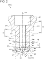
- FIG. 1 is a schematic cross-sectional view of a precombustion chamber gas engine according to an example (not part of the invention).
- the precombustion chamber gas engine 1 according to some examples and embodiments includes a main-chamber forming portion 2 forming a main combustion chamber 20 (main chamber) of the engine, and a precombustion-chamber forming portion 3 forming a precombustion chamber 30 communicating with the main combustion chamber 20 via a plurality of nozzle holes 4.
- the precombustion chamber gas engine 1 includes: a cylinder 13 including a cylinder block 11 having therein a tubular structure of cylindrical shape and a cylinder head 12 having therein a recessed structure capable of capping the top of the tubular structure; a piston 14 reciprocably disposed within the cylinder 13; and a precombustion chamber cap 19 made of nickel-based alloy, for example.
- the main combustion chamber 20 is defined between the cylinder 13 and the piston 14.
- the precombustion chamber 30 is defined by the precombustion chamber cap 19 disposed on the cylinder head 12 so as to be positioned above the main combustion chamber 20 (on the opposite side from the piston 14).
- the cylinder 13 and the piston 14 form the main-chamber forming portion 2
- the precombustion chamber cap 19 forms the precombustion-chamber forming portion 3.
- the precombustion-chamber forming portion 3 includes a plurality of nozzle holes 4 connecting the precombustion chamber 30 formed in the precombustion-chamber forming portion 3 to the outside.
- the main combustion chamber 20 communicates with the precombustion chamber 30 via the plurality of nozzle holes 4.
- the precombustion-chamber forming portion 3 includes a small-diameter-cylinder forming portion 31 which forms a small-diameter cylinder chamber 310 of cylindrical shape having a predetermined inner diameter and connected to the plurality of nozzle holes 4 and a large-diameter-cylinder forming portion 32 which forms a large-diameter cylinder chamber 320 of cylindrical shape having an inner diameter larger than that of the small-diameter cylinder chamber 310. That is, the precombustion chamber 30 includes the small-diameter cylinder chamber 310 and the large-diameter cylinder chamber 320.
- the precombustion chamber 30 may have other shape, for example, a cylindrical shape having a constant inner diameter.
- the precombustion chamber central axis CS coincides with the central axis of the small-diameter cylinder chamber 310.
- the main chamber central axis CM coincides with the precombustion chamber central axis CS
- the precombustion chamber central axis CS may be inclined with respect to the main chamber central axis CM.
- the central axis of the small-diameter cylinder chamber 310 may not coincide with the central axis of the large-diameter cylinder chamber 320.
- the precombustion chamber gas engine 1 further includes an ignition device 6 disposed in the large-diameter cylinder chamber 320 of the precombustion chamber 30, and a precombustion-chamber-gas supply device 7 for directly supplying a precombustion chamber fuel gas to the precombustion chamber 30 not via the main combustion chamber 20.
- the ignition device 6 has an ignition portion 61 capable of igniting an air-fuel mixture.
- the ignition device 6 is an ignition plug, and the ignition device 6 is mounted on the engine so that an electrode (ignition portion 61) of the ignition plug is positioned on the precombustion chamber central axis CS.
- the ignition device 6 may be disposed such that the ignition portion 61 is at a predetermined distance from the precombustion chamber central axis CS.
- the precombustion-chamber-gas supply device 7 is configured to supply a precombustion chamber fuel gas to the large-diameter cylinder chamber 320, and the supply of the precombustion chamber fuel gas to the precombustion chamber 30 is controlled by a precombustion-chamber-fuel-gas supply valve 71.
- the precombustion chamber gas engine 1 further includes an intake port 15 and an exhaust port 16 connected around the cylinder head 12; an intake valve 17 for opening and closing the intake port 15; and an exhaust valve 18 for opening and closing the exhaust port 16.
- the precombustion chamber gas engine 1 having the above configuration opens the intake valve 17 and closes the exhaust valve 18 when the piston 14 moves downward in the intake stroke, for instance.
- a lean premixed gas containing fuel gas and air is introduced into the cylinder 13 through the intake port 15 connected to the intake valve 17.
- the precombustion-chamber-fuel-gas supply valve 71 opens, the precombustion chamber fuel gas is introduced into the precombustion chamber 30. Meanwhile, in the compression stroke, the precombustion-chamber-fuel-gas supply valve 71 closes when the piston 14 moves upward.
- the lean premixed gas introduced into the cylinder 13 through the intake port 15 is compressed as the piston 14 moves upward, and a part of the lean premixed gas is introduced into the precombustion chamber 30 through each of the nozzle holes 4 of the precombustion chamber 30.
- the lean premixed gas introduced from the main combustion chamber 20 to the precombustion chamber 30 is mixed with the precombustion chamber fuel gas to produce an air-fuel mixture having a concentration suitable for ignition in the precombustion chamber 30.
- the air-fuel mixture in the precombustion chamber 30 is ignited by the ignition device 6 at a predetermined timing when the piston 14 arrives at the vicinity of the compression top dead center, so that the air-fuel mixture in the precombustion chamber 30 is combusted. Combustion flames generated by this combustion is injected into the cylinder 13 through each of the nozzle holes and ignite the lean premixed gas in the cylinder 13, which leads to combustion of the lean premixed gas in the main combustion chamber 20.
- the present inventors have found that, as described later, when the precombustion-chamber forming portion 3 has a thin region 5 or a thin region 8 to reduce the heat capacity and stiffness around the nozzle holes 4 and to flatten the temperature distribution (temperature difference) around the nozzle holes, it is possible to reduce thermal stress around the nozzle holes 4, and suppress the occurrence of crack around the nozzle holes 4.
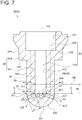
- FIGs. 2 , 3 , 5 , and 7 are each a schematic cross-sectional view of a precombustion-chamber forming portion according to an embodiment or an example.
- FIG. 3 is a diagram for describing an outer recess formed in an outer peripheral surface of a tip portion facing a main combustion chamber.
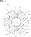
- FIG. 4 is a schematic cross-sectional view taken along line A-A in FIG. 3 .
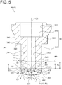
- FIG. 5 is a diagram for describing a thin region formed in a tip portion.
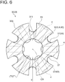
- FIG. 6 is a schematic cross-sectional view taken along line B-B in FIG. 5 .
- FIG. 7 is a diagram for describing an inner recess formed in an inner peripheral surface of a tip portion facing a precombustion chamber.
- FIG. 3 is a diagram for describing an outer recess formed in an outer peripheral surface of a tip portion facing a main combustion chamber.
- FIG. 4 is a schematic cross-sectional view taken along line A-A in FIG. 3 .
- FIG. 8 is a schematic cross-sectional view taken along line C-C in FIG. 7 .
- the line A-A in FIG. 3 , the line B-B in FIG. 5 , and the line C-C in FIG. 7 pass through an upper edge 411 of a precombustion-chamber-side opening 41 of the nozzle hole 4 and extend in a direction perpendicular to the precombustion chamber central axis CS.
- the precombustion-chamber forming portion 3 of the precombustion chamber gas engine 1 includes a cylindrical portion 34 extending along the extension direction (vertical direction in the figures) of the precombustion chamber central axis CS of the precombustion-chamber forming portion 3, and a tip portion 33 closing one end (lower end) of the cylindrical portion 34 closer to the main combustion chamber 20.
- the cylindrical portion 34 includes a small-diameter cylindrical portion 341 of cylindrical shape and a large-diameter cylindrical portion 342 of cylindrical shape having a larger outer diameter than the small-diameter cylindrical portion 341.
- a stepped surface 343 is formed between an outer peripheral surface 344 of the small-diameter cylindrical portion 341 and an outer peripheral surface 345 of the large-diameter cylindrical portion 342.
- the stepped surface 343 of the cylindrical portion 34 abuts on an unillustrated portion of the cylinder head 12, or is in contact with the cylinder head 12 via an unillustrated component such as a seal member so that the precombustion-chamber forming portion 3 is supported by the cylinder head 12.
- the large-diameter cylinder chamber 320 of the precombustion-chamber forming portion 3 is formed in cylindrical shape having a constant internal diameter, and a stepped surface 322 is formed between a wall surface 321 of the large-diameter cylinder chamber 320 and a wall surface 312 of the small-diameter cylinder chamber 310.
- the tip portion 33 has a plurality of nozzle holes 4 whose central axes CP are inclined with respect to the precombustion chamber central axis CS.
- D represents the nozzle hole diameter
- L represents the nozzle hole length of the nozzle hole 4.
- the nozzle hole diameter D and the nozzle hole length L are determined by the combustion performance of the precombustion chamber gas engine 1 and the internal pressure of the precombustion-chamber forming portion 3.
- the nozzle holes 4 are arranged at intervals in the circumferential direction, as shown in FIGs. 4 , 6 , and 8 .
- the tip portion 33 is formed integrally with a lower end of the small-diameter cylindrical portion 341 opposite to an upper end that is formed integrally with the large-diameter cylindrical portion 342.
- the tip portion 33 protrudes from the lower end of the small-diameter cylindrical portion 341 and has a convex tip surface 332.
- the tip portion 33 may be recessed inward from the lower end of the small-diameter cylindrical portion 341 and has a concave tip surface.
- the tip portion 33 may be formed so as to extend along a direction perpendicular to the extension direction of the precombustion chamber central axis CS and has a flat tip surface.
- the tip portion 33 has a thin region 5 having a thickness T satisfying T ⁇ L, where L is the length of the nozzle hole 4.
- the tip portion 33 of the precombustion-chamber forming portion 3 has the thin region 5 having a thickness T satisfying T ⁇ L, where L is the length of the nozzle hole 4. Since the tip portion 33 has the plurality of nozzle holes 4, the thin region 5 is formed around the nozzle holes 4. When such a thin region 5 is formed around the nozzle holes 4 of the tip portion 33, which are largely affected by heat of the combustion flame, it is possible to reduce the heat capacity and stiffness around the nozzle holes 4, and it is possible to flatten the temperature distribution (temperature difference) around the nozzle holes 4 at temperature rise.
- Reducing the heat capacity and stiffness around the nozzle holes 4 facilitates thermal deformation (thermal expansion and thermal contraction) around the nozzle holes 4, thus reducing thermal strain around the nozzle holes 4 and thermal stress generated due to confinement of the thermal strain. Further, flattening the temperature distribution around the nozzle holes 4 at temperature rise suppresses non-uniform thermal deformation around the nozzle holes 4, thus reducing thermal strain around the nozzle holes 4 and thermal stress generated due to confinement of the thermal strain. Consequently, it is possible to suppress the occurrence of crack around the nozzle holes 4 due to heat fatigue.
- the thin region 5 includes a tip 331 of the tip portion 33.
- the tip 331 of the tip portion 33 is an end opposite to an end integrally connected with the cylindrical portion 34 with respect to the extension direction of the precombustion chamber central axis CS.
- the precombustion-chamber forming portion 3 includes a precombustion-chamber forming portion 3A, 3C having the thin region 5 including a first thin region 51.
- the tip portion 33 of the precombustion-chamber forming portion 3A, 3C has a thickness gradually decreasing toward the tip 331 in a region from a lower edge 422 of a main-combustion-chamber-side opening 42 of the nozzle hole 4 to the tip 331 in the extension direction of the precombustion chamber central axis CS.
- a tip surface 332 is formed which has a smaller curvature than an outer peripheral surface 333 forming an outer periphery of a portion whose thickness is equal to the nozzle hole length L. Accordingly, the thickness T of a portion where the tip surface 332 of the tip portion 33 forms the outer periphery is smaller than the nozzle hole length L of the nozzle hole 4.
- the first thin region 51 is formed from the tip 331 to a lower side of a lower edge 412 of the precombustion-chamber-side opening 41 in the extension direction of the precombustion chamber central axis CS.
- the first thin region 51 does not include the peripheral edge of the nozzle hole 4, i.e., the precombustion-chamber-side opening 41 and the main-combustion-chamber-side opening 42 of the nozzle hole 4.
- the thin region 5 (first thin region 51) includes the tip 331 of the tip portion 33, the thickness of the tip 331 of the tip portion 33 is reduced compared to when the thin region 5 is not present in the tip 331 of the tip portion 33.
- the heat capacity and stiffness around the nozzle holes 4 are reduced, and the temperature distribution around the nozzle holes 4 at temperature rise is flattened.
- the thin region 5 including the tip 331 of the tip portion 33 can be easily formed in the precombustion-chamber forming portion 3 having no thin region 5 in the tip 331 of the tip portion 33, by cutting or the like.
- the thin region 5 (second thin region 52, third thin region 53) includes a portion of the tip portion 33 between a pair of nozzle holes 4 adjacent in the circumferential direction of the tip portion 33.
- the thickness T1 of a part of the precombustion-chamber forming portion 3 in the circumferential direction in a plane passing through the upper edge 411 of the precombustion-chamber-side opening 41 of the nozzle hole 4 and extending in a direction perpendicular to the precombustion chamber central axis CS is equal to the nozzle hole length L of the nozzle hole 4.
- the precombustion-chamber forming portion 3 includes a precombustion-chamber forming portion 3B having the thin region 5 including a second thin region 52.
- the precombustion-chamber forming portion 3C has the thin region 5 including, in addition to the first thin region 51 described above, the second thin region 52.
- the second thin region 52 is formed in the tip portion 33 between each pair of nozzle holes 4 adjacent in the circumferential direction of the tip portion 33.
- the precombustion-chamber forming portion 3 includes a precombustion-chamber forming portion 3D having the thin region 5 including a third thin region 53.
- the third thin region 53 is formed in the tip portion 33 between each pair of nozzle holes 4 adjacent in the circumferential direction of the tip portion 33.
- the thin region 5 (second thin region 52, third thin region 53) includes a portion of the tip portion 33 between a pair of nozzle holes 4 adjacent in the circumferential direction of the tip portion 33, the thickness of the portion between the pair of circumferentially adjacent nozzle holes 4 is reduced.
- the heat capacity and stiffness around the pair of nozzle holes 4 are reduced, and the temperature distribution around the pair of nozzle holes 4 at temperature rise is flattened. As a result, it is possible to suppress the occurrence of crack around the nozzle holes 4 due to heat fatigue.
- the second thin region 52 includes at least one outer recess 36, 37 (recess 35) formed in an outer peripheral surface (tip surface 332, outer peripheral surface 333) of the tip portion 33 facing the main combustion chamber 20.
- the outer recess 36, 37 is formed at least from the lower edge 422 of the main-combustion-chamber-side opening 42 to the upper edge 411 of the precombustion-chamber-side opening 41 in the extension direction of the precombustion chamber central axis CS.
- a plurality of outer recesses 36, 37 are formed in the tip portion 33.
- the outer recesses 36, 37 are arranged at intervals in the circumferential direction of the tip portion 33, one between each pair of nozzle holes 4 adjacent in the circumferential direction of the tip portion 33.
- the precombustion-chamber forming portion 3B has a constant thickness in portions, not provided with the outer recess 36, of the tip portion 33 and the cylindrical portion 34 from the stepped surface 343 to the tip portion 33 in the extension direction of the precombustion chamber central axis CS.
- each outer recess 36 is shaped into a slit extending from the tip surface 332 of the tip portion 33 to the stepped surface 343 of the cylindrical portion 34 in the extension direction of the precombustion chamber central axis CS.
- the outer recesses 36 are recessed from the tip surface 332 of the tip portion 33 and the outer peripheral surface 344 of the small-diameter cylindrical portion 341 so as to have arc-shaped bottom surfaces on the inner side (a side facing the precombustion chamber 30). Accordingly, as shown in FIG. 4 , the thickness T of a part of the tip portion 33 in the circumferential direction provided with the outer recess 36 is less than the thickness T1 of a remaining part in the circumferential direction not provided with the outer recess 36.
- the thickness T1 is equal to the nozzle hole length L of the nozzle hole 4, as described above.
- the precombustion-chamber forming portion 3C has a constant thickness in portions, not provided with the outer recess 37, of the cylindrical portion 34 from the stepped surface 343 to the tip portion 33 in the extension direction of the precombustion chamber central axis CS and of the tip portion 33 including the lower edge 422 of the main-combustion-chamber-side opening 42 of the nozzle hole 4 and adjacent to the cylindrical portion 34.
- each outer recess 37 is shaped into a slit extending from the tip surface 332 of the tip portion 33 to the lower end of the small-diameter cylindrical portion 341 in the extension direction of the precombustion chamber central axis CS.
- the outer recesses 37 are recessed from the outer peripheral surface 333 of the tip portion 33 and the outer peripheral surface 344 of the small-diameter cylindrical portion 341 so as to have a contact depth and an arc-shaped bottom surface on the inner side (a side facing the precombustion chamber 30). Accordingly, as shown in FIG. 6 , the thickness T of a part of the tip portion 33 in the circumferential direction provided with the outer recess 37 is less than the thickness T1 of a remaining part in the circumferential direction not provided with the outer recess 37.
- the thickness T1 is equal to the nozzle hole length L of the nozzle hole 4 as described above.
- the thin region 5 (second thin region 52) includes at least one outer recess 36, 37 formed in an outer peripheral surface (tip surface 332, outer peripheral surface 333) of the tip portion 33 facing the main combustion chamber 20.
- the thin region 5 is defined by the at least one outer recess 36, 37 formed in the outer peripheral surface of the tip portion 33, it is possible to reduce thermal strain around the main-combustion-chamber-side openings 42 of the nozzle holes 4 and thermal stress generated due to confinement of the thermal strain.
- the outer recess 36, 37 can be easily formed in the outer peripheral surface of the tip portion 33, by cutting or the like.
- the third thin region 53 includes at least one inner recess 38 (recess 35) formed in an inner peripheral surface (bottom surface 311, wall surface 312) of the tip portion 33 facing the precombustion chamber 30.
- the inner recess 38 is formed at least from the lower edge 422 of the main-combustion-chamber-side opening 42 to the upper edge 411 of the precombustion-chamber-side opening 41 in the extension direction of the precombustion chamber central axis CS.
- a plurality of inner recesses 38 are formed in the tip portion 33. The inner recesses 38 are arranged at intervals in the circumferential direction of the tip portion 33, one between each pair of nozzle holes 4 adjacent in the circumferential direction of the tip portion 33.
- the precombustion-chamber forming portion 3D has a constant thickness in a portion, not provided with the inner recess 38, of the tip portion 33 and of the cylindrical portion 34 from the stepped surface 343 to the tip portion 33 in the extension direction of the precombustion chamber central axis CS.
- each inner recess 38 is shaped into a slit extending from the bottom surface 311 of the small-diameter cylinder chamber 310 to the stepped surface 322 of the large-diameter cylinder chamber 320 in the extension direction of the precombustion chamber central axis CS.
- the inner recesses 38 are recessed from the bottom surface 311 and the wall surface 312 of the small-diameter cylinder chamber 310 so as to have a contact depth and an arc-shaped bottom surface on the inner side (a side facing the main combustion chamber 20). As shown in FIG. 8 , the inner recesses 38 are connected to each other at the bottom surface 311 of the small-diameter cylinder chamber 310. Accordingly, as shown in FIG. 8 , the thickness T of a part of the tip portion 33 in the circumferential direction provided with the inner recess 38 is less than the thickness T1 of a remaining part in the circumferential direction not provided with the inner recess 38.
- the thickness T1 is equal to the nozzle hole length L of the nozzle hole 4 as described above.
- the thin region 5 (third thin region 53) includes at least one inner recess 38 formed in an inner peripheral surface (bottom surface 311, wall surface 312) of the tip portion 33 facing the precombustion chamber 30.
- the thin region 5 is defined by the at least one inner recess 38 formed in the inner peripheral surface of the tip portion 33, it is possible to reduce thermal strain around the precombustion-chamber-side openings 41 of the nozzle holes 4 and thermal stress generated due to confinement of the thermal strain.
- the inner recess 38 is formed to the stepped surface 343 of the cylindrical portion 34 in the extension direction of the precombustion chamber central axis CS, the inner recess 38 can be easily formed on the inner side of the tip portion 33 by cutting or the like.
- the recess 35 extends from the tip portion 33 over at least a part of the cylindrical portion 34 across the reference plane RP along the extension direction of the precombustion chamber central axis CS.
- the recess 35 extends from the tip portion 33 over at least a part of the cylindrical portion 34 along the extension direction of the precombustion chamber central axis CS, the at least part of the cylindrical portion 34 adjacent to the tip portion 33 has a reduced thickness.
- the at least part of the cylindrical portion 34 adjacent to the tip portion 33 can be easily deformed by heat, so that heat in the tip portion 33 easily transfers to the cylindrical portion 34.
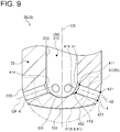
- FIG. 9 is a schematic enlarged cross-sectional view of the vicinity of a tip portion of a precombustion-chamber forming portion according to another example for describing a chamfered shape formed on the edge of a precombustion-chamber-side opening of a nozzle hole.
- the precombustion-chamber forming portion 3 includes a precombustion-chamber forming portion 3E having a chamfered portion 414 on the precombustion-chamber-side opening 4. As shown in FIG.
- the precombustion-chamber forming portion 3E has the same configuration as the precombustion-chamber forming portion 3C except that the chamfered portion 414 of C-chamfer plane is formed over the entire peripheral edge of the precombustion-chamber-side opening 41.
- the chamfered portion 414 may be formed on the precombustion-chamber-side opening 41 of the precombustion-chamber forming portion 3A, 3B, 3D, and 3G described later. Further, the chamfered portion may be formed over the entire periphery of the main-combustion-chamber-side opening 42.
- the precombustion-chamber forming portion 3E has the chamfered portion 414 on the precombustion-chamber-side opening 41, the temperature of the portion forming the precombustion-chamber-side opening 41 is reduced compared to when the chamfered portion 414 is not provided.
- Temperature analysis was performed on the basis of temperature analysis and temperature analysis results for the precombustion-chamber forming portion 3 of the precombustion chamber gas engine 1 according to the above embodiments. Details will be described. Temperature analysis was performed with varying thermal conditions, e.g., varying atmosphere temperature and heat transfer coefficient during engine operation, according to each surface such as the tip surface 332 and the outer peripheral surface 333 of the tip portion 33 of the precombustion-chamber forming portion 3 (precombustion chamber cap 19) disposed on the cylinder head 12, the stepped surface 343 and the outer peripheral surface 344 of the cylindrical portion 34, and the bottom surface 311 and the wall surface 312 of the small-diameter cylinder chamber 310, to estimate the temperature change of the precombustion-chamber forming portion 3.
- thermal conditions e.g., varying atmosphere temperature and heat transfer coefficient during engine operation
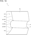
- FIG. 10 is a diagram for describing temperature analysis result and stress analysis result around a nozzle hole of a precombustion-chamber forming portion.
- the temperature of the precombustion-chamber-side opening 41 of the nozzle hole 4 shown in FIG. 10 more rapidly changed than the other part of the precombustion-chamber forming portion 3 and was raised to higher temperature than the other part of the precombustion-chamber forming portion 3.
- stress analysis was performed to estimate strain change and calculate a strain range at each of measurement points P1 to P3.
- the measurement point P1 is located on the upper edge 411 of the precombustion-chamber-side opening 41, and the measurement point P3 is located on the lower edge 412 of the precombustion-chamber-side opening 41.
- the measurement point P2 is located on an intermediate edge 413 between the upper edge 411 and the lower edge 412 of the precombustion-chamber-side opening 41 in the extension direction of the precombustion chamber central axis CS. If the precombustion-chamber-side opening 41 has the chamfered portion 414 as described above, as shown in FIG. 9 , the upper edge 411, the lower edge 412, and the intermediate edge 413 are disposed on the peripheral edge of the chamfered portion 414 closer to the main combustion chamber 20.
- FIG. 11 is a table showing a dimensionless strain range of a precombustion-chamber-side opening of a precombustion-chamber forming portion having a first thin region, compared to a precombustion-chamber forming portion not having the thin region.
- FIG. 12 is a table showing a dimensionless strain range of a precombustion-chamber-side opening of a precombustion-chamber forming portion having a first thin region, a second thin region, and a chamfered shape on the edge of a precombustion-chamber-side opening, compared to a precombustion-chamber forming portion not having the thin region.
- 3F in FIGs. 11 and 12 is a precombustion-chamber forming portion having a tip as shown by the two-dot chain line in FIG. 2 and not having the thin region 5.
- strain ranges of the precombustion-chamber forming portion 3F and the precombustion-chamber forming portion 3A at each measurement point P1 to P3 are expressed dimensionlessly as the ratio when the strain range of the precombustion-chamber forming portion 3F is 1, and the reduction rate of the precombustion-chamber forming portion 3A with respect to the precombustion-chamber forming portion 3F is shown.
- the precombustion-chamber forming portion 3A having the first thin region 51 has a reduced strain range at the measurement point P2, compared to the precombustion-chamber forming portion 3F.
- the precombustion-chamber forming portion 3A can suppress the occurrence of crack generated between a pair of circumferentially adjacent nozzle holes 4, compared to the precombustion-chamber forming portion 3F.
- strain ranges of the precombustion-chamber forming portion 3F and the precombustion-chamber forming portion 3E at each measurement point P1 to P3 are expressed dimensionlessly as the ratio when the strain range of the precombustion-chamber forming portion 3F is 1, and the reduction rate of the precombustion-chamber forming portion 3E with respect to the precombustion-chamber forming portion 3F is shown. As shown in FIG. 12 , strain ranges of the precombustion-chamber forming portion 3F and the precombustion-chamber forming portion 3E at each measurement point P1 to P3 are expressed dimensionlessly as the ratio when the strain range of the precombustion-chamber forming portion 3F is 1, and the reduction rate of the precombustion-chamber forming portion 3E with respect to the precombustion-chamber forming portion 3F is shown. As shown in FIG.
- the precombustion-chamber forming portion 3E having the first thin region 51, the second thin region 52, and the chamfered portion 414 on the precombustion-chamber-side opening 41 has reduced strain ranges at all measurement points P1 to P3, compared to the precombustion-chamber forming portion 3F.
- the precombustion-chamber forming portion 3E has a larger reduction rate with respect to the precombustion-chamber forming portion 3F than the precombustion-chamber forming portion 3A shown in FIG. 11 .
- the precombustion-chamber forming portion 3E can reduce thermal stress generated around the nozzle holes 4 and suppress the occurrence of crack, compared to the precombustion-chamber forming portions 3A and 3F.
- the tip portion 33 has the thin region 5 having a thickness T satisfies T ⁇ L
- the tip portion 33 has a thin region 8 having a thickness T satisfies T ⁇ T0. Details will be described.
- the precombustion-chamber forming portion 3 of the precombustion chamber gas engine 1 includes the cylindrical portion 34 extending along the extension direction (vertical direction in the figures) of the precombustion chamber central axis CS of precombustion-chamber forming portion 3, and the tip portion 33 closing one end (lower end) of the cylindrical portion 34 closer to the main combustion chamber 20.
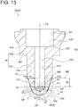
- FIG. 13 is a schematic cross-sectional view of a precombustion-chamber forming portion according to another embodiment.
- the reference plane RP passes through a position 346 away from the upper edge 411 of the precombustion-chamber-side opening 41 of the nozzle hole 4 by a reference length RL in a direction opposite to the main combustion chamber 20 (lower side in the figures) along the extension direction of the precombustion chamber central axis CS and extends in a direction perpendicular to the precombustion chamber central axis CS.
- the reference length RL is three times (predetermined times) the nozzle hole diameter D of the nozzle hole 4. As shown in FIGs.
- the tip portion 33 is located on the main combustion chamber 20 side of the reference plane RP.
- the reference plane RP is away from the nozzle hole 4 and thus is less affected by heat of the combustion flame.
- the tip portion 33 located closer to the main combustion chamber 20 than the reference plane RP is greatly affected by heat of the combustion flame. Accordingly, the provision of the thin region 8 is more effective in the tip portion 33 than in the cylindrical portion 34.
- the tip portion 33 has the thin region 8 having a thickness T satisfying T ⁇ T0, where T0 is the thickness of the precombustion-chamber forming portion 3 at the reference plane RP.
- T0 is the thickness of the precombustion-chamber forming portion 3 at the reference plane RP.
- a portion of the precombustion-chamber forming portion 3 between the reference plane RP and a plane passing through the upper edge 411 of the precombustion-chamber-side opening 41 of the nozzle hole 4 and extending in a direction perpendicular to the precombustion chamber central axis CS has a cylindrical shape with a constant cross-sectional shape along a direction perpendicular to the precombustion chamber central axis CS.
- the thickness T1 of a part of the tip portion 33 in the circumferential direction in a cross-section passing through the upper edge 411 of the precombustion-chamber-side opening 41 of the nozzle hole 4 and extending in a direction perpendicular to the precombustion chamber central axis CS is equal to the thickness T0 at the reference plane RP.
- the thickness T1 is equal to the nozzle hole length L of the nozzle hole 4.
- the thickness is not constant in the circumferential direction, in this case, the maximum thickness in the circumferential direction is the thickness T0 or the thickness T1.
- the thin region 8 includes a first thin region 81 that is identical to the first thin region 51 of the thin region 5.
- the thin region 8 includes a second thin region 82 that is identical to the second thin region 52 of the thin region 5.
- the second thin region 82 includes a portion of the tip portion 33 between a pair of nozzle holes 4 adjacent in the circumferential direction of the tip portion 33.
- the second thin region 82 includes at least one outer recess 36, 37 formed in an outer peripheral surface (tip surface 332, outer peripheral surface 333) of the tip portion 33 facing the main combustion chamber 20.
- the thin region 8 includes a third thin region 83 that is identical to the third thin region 53 of the thin region 5. Accordingly, the third thin region 83 includes a portion of the tip portion 33 between a pair of nozzle holes 4 adjacent in the circumferential direction of the tip portion 33. Further, the third thin region 83 includes at least one inner recess 38 (recess 35) formed in an inner peripheral surface (bottom surface 311, wall surface 312) of the tip portion 33 facing the precombustion chamber 30.
- the precombustion-chamber forming portion 3 includes a precombustion-chamber forming portion 3G having the thin region 8 including a fourth thin region 84.
- the tip portion 33 of the precombustion-chamber forming portion 3G has a thickness gradually decreasing toward the tip 331 in a region from the upper edge 421 of the main-combustion-chamber-side opening 42 of the nozzle hole 4 to the cylindrical portion 34 in the extension direction of the precombustion chamber central axis CS and a constant thickness equal to the nozzle hole length L1 in a region from the upper edge 421 to the tip 331.
- the thickness T of the tip portion 33 is less than the thickness T0 at the reference plane RP.
- the fourth thin region 84 is formed from the tip 331 to an upper side of the upper edge 421 of the main-combustion-chamber-side opening 42 in the extension direction of the precombustion chamber central axis CS.
- the tip portion 33 of the precombustion-chamber forming portion 3 is located on the main combustion chamber 20 side of the reference plane RP passing through a position 346 away from the upper edge 411 of the precombustion-chamber-side opening 41 of the nozzle hole 4 by a reference length RL, i.e., by a length three times (predetermined times) the nozzle hole diameter D of the nozzle hole 4, in a direction opposite to the main combustion chamber 20 along the extension direction of the precombustion chamber central axis CS and extending in a direction perpendicular to the precombustion chamber central axis CS.
- the tip portion 33 has the thin region 8 having a thickness T satisfying T ⁇ T0, where T0 is the thickness of the precombustion-chamber forming portion 3 at the reference plane RP.
- T0 is the thickness of the precombustion-chamber forming portion 3 at the reference plane RP.
- the thickness T of the thin region 8 is less than that at the reference plane RP which is less affected by the combustion flame.
- Reducing the heat capacity and stiffness around the nozzle holes 4 facilitates thermal deformation (thermal expansion and thermal contraction) around the nozzle holes 4, thus reducing thermal strain around the nozzle holes 4 and thermal stress generated due to confinement of the thermal strain. Further, flattening the temperature distribution around the nozzle holes 4 at temperature rise suppresses non-uniform thermal deformation around the nozzle holes 4, thus reducing thermal strain around the nozzle holes 4 and thermal stress generated due to confinement of the thermal strain. Consequently, it is possible to suppress the occurrence of crack around the nozzle holes 4 due to heat fatigue.
- the thin region 8 (first thin region 81, fourth thin region 84) includes the tip 331.
- the thin region 8 (first thin region 81, fourth thin region 84) includes the tip 331 of the tip portion 33, the thickness of the tip 331 of the tip portion 33 is reduced compared to when the thin region 8 is not present in the tip 331 of the tip portion 33.
- the heat capacity and stiffness around the nozzle holes 4 are reduced, and the temperature distribution around the nozzle holes 4 at temperature rise is flattened.
- the thin region 8 including the tip 331 of the tip portion 33 can be easily formed in the precombustion-chamber forming portion 3 having no thin region 8 in the tip 331 of the tip portion 33, by cutting or the like.
- the thin region 8 (fourth thin region 84) includes at least a part of the peripheral edge of the main-combustion-chamber-side opening 42 of the nozzle hole 4 in the tip portion 33.
- the peripheral edge of the main-combustion-chamber-side opening 42 includes the upper edge 421 and the lower edge 422 as shown in FIG. 13 .
- the fourth thin region 84 includes both the upper edge 421 and the lower edge 422 of the main-combustion-chamber-side opening 42 of the nozzle hole 4.
- the thin region 8 (fourth thin region 84) includes at least a part of the peripheral edge of the main-combustion-chamber-side opening 42 of the nozzle hole 4 in the tip portion 33, the thickness around the nozzle holes 4 is reduced.
- the heat capacity and stiffness around the nozzle holes 4 are reduced, and the temperature distribution around the nozzle holes 4 at temperature rise is flattened. As a result, it is possible to suppress the occurrence of crack around the nozzle holes 4 due to heat fatigue.
- the reference length RL between the upper edge 411 and the position 346 is three times (predetermined times) the nozzle hole diameter D of the nozzle hole 4, the reference length RL may be longer or shorter than three times the nozzle hole diameter D, for example, equal to or twice the nozzle hole diameter D of the nozzle hole 4.
- the reference length RL may be zero.
- the reference plane RP may be disposed in a position according to the reference length RL.
- the thin region 5 is a region having a thickness T satisfying T ⁇ T0
- the thin region 8 is a region having a thickness T satisfying T ⁇ L
- the thickness T of the thin region 5 or the thin region 8 may be set to a minimum that can withstand the internal pressure applied to the precombustion-chamber forming portion 3.
- a thinner thickness T provides less strength than a thicker thickness T, but provides less heat capacity and stiffness around the nozzle holes 4, thus reducing thermal stress generated around the nozzle holes 4.
- the thin region 5 or the thin region 8 is within the above range, it is possible to effectively suppress the occurrence of crack while maintaining strength necessary for the precombustion-chamber forming portion 3.
- the thin region 5 or the thin region 8 does not include the peripheral edge of the precombustion-chamber-side opening 41 and the main-combustion-chamber-side opening 42 of the nozzle hole 4. In this case, since the nozzle hole diameter D and the nozzle hole length L of the nozzle hole 4 are maintained, it is possible to maintain the performance of the combustion flame injected from the nozzle hole 4.
- the recess 35 is formed along the extension direction of the precombustion chamber central axis CS.
- the recess may be formed along another direction.
- the recess may be formed along the circumferential direction of the tip portion 33 or the cylindrical portion 34.
Landscapes
- Engineering & Computer Science (AREA)
- Chemical & Material Sciences (AREA)
- Combustion & Propulsion (AREA)
- Mechanical Engineering (AREA)
- General Engineering & Computer Science (AREA)
- Combustion Methods Of Internal-Combustion Engines (AREA)
Claims (7)
- Gasmotor mit Vorverbrennungskammer, umfassend:einen Hauptkammerbildungsabschnitt (2), der eine Hauptverbrennungskammer (20) bildet; undeinen Vorverbrennungskammerbildungsabschnitt (3), der eine Vorverbrennungskammer (30) bildet, die mit der Hauptverbrennungskammer (20) über eine Vielzahl von Düsenlöchern (4) kommuniziert,wobei der Vorverbrennungskammerbildungsabschnitt (3) einen zylindrischen Abschnitt (34), der sich entlang einer Ausdehnungsrichtung einer Vorverbrennungskammermittelachse (CS) des Vorverbrennungskammerbildungsabschnitts (3) erstreckt, und einen Spitzenabschnitt (33), der ein Hauptverbrennungskammerseitenende des zylindrischen Abschnitts (34) schließt und die Düsenlöcher (4) aufweist, beinhaltet,wobei der Spitzenabschnitt (33) eine dünne Region (52), aufweisend eine Dicke T einer Wandoberfläche (312) des Spitzenabschnitts (33), beinhaltet, die T<L erfüllt, wo L eine Länge jedes Düsenlochs (4) ist, unddadurch gekennzeichnet, dass
die dünne Region (52) eine Vielzahl von Vertiefungen (35) beinhaltet, die in einer Region gebildet sind, die einen Abschnitt des Spitzenabschnitts (33) zwischen jedem eines Paars von Düsenlöchern (4) nebeneinander in einer Umfangsrichtung des Spitzenabschnitts (33) beinhaltet; wobei jede Vertiefung (35) zu einem Schlitz geformt ist, der sich von einer internen Bodenfläche (311) oder von einer externen Spitzenfläche (332) des Spitzenabschnitts (33) in der Ausdehnungsrichtung der Vorverbrennungskammermittelachse (CS) erstreckt. - Gasmotor mit Vorverbrennungskammer, umfassendeinen Hauptkammerbildungsabschnitt (2), der eine Hauptverbrennungskammer (20) bildet; undeinen Vorverbrennungskammerbildungsabschnitt (3, 3A-3G), der eine Vorverbrennungskammer (30) bildet, die mit der Hauptverbrennungskammer (20) über eine Vielzahl von Düsenlöchern (4) kommuniziert,wobei der Vorverbrennungskammerbildungsabschnitt (3, 3A-3G) einen zylindrischen Abschnitt (34), der sich entlang einer Ausdehnungsrichtung einer Vorverbrennungskammermittelachse des Vorverbrennungskammerbildungsabschnitts (3, 3A-3G) erstreckt, und einen Spitzenabschnitt (33), der ein Hauptverbrennungskammerseitenende des zylindrischen Abschnitts (34) schließt und die Düsenlöcher (4) aufweist, beinhaltet,wobei der Spitzenabschnitt (33) an einer Hauptverbrennungskammerseite einer Referenzebene (RP), die sich in einer Richtung senkrecht zu der Vorverbrennungskammermittelachse erstreckt, an einer Position, die von einer oberen Kante (411) einer Vorverbrennungskammerseitenöffnung (41) jedes Düsenlochs (4) um eine Länge (RL), die ein vorgegebenes Vielfaches eines Durchmessers (D) jedes Düsenlochs (4) ist, in einer Richtung entgegengesetzt zu der Hauptverbrennungskammer (2) entlang der Ausdehnungsrichtung der Vorverbrennungskammermittelachse entfernt ist, liegt,wobei der Spitzenabschnitt (33) eine dünne Region (8) mit einer Dicke T einer Wandoberfläche (312) des Spitzenabschnitts (33) beinhaltet, die T<T0 erfüllt, wo T0 eine Dicke des Vorverbrennungskammerbildungsabschnitts an der Referenzebene (RP) ist, unddadurch gekennzeichnet, dassdie dünne Region (8) eine Vielzahl von Vertiefungen (35) beinhaltet, die in einer Region gebildet sind, die einen Abschnitt des Spitzenabschnitts (33) zwischen jedem eines Paars von Düsenlöchern (4) nebeneinander in einer Umfangsrichtung des Spitzenabschnitts (33) beinhaltet; wobei jede Vertiefung (35) zu einem Schlitz geformt ist, der sich von einer internen Bodenfläche (311) oder von einer externen Spitzenfläche (332) des Spitzenabschnitts (33) in der Ausdehnungsrichtung der Vorverbrennungskammermittelachse (CS) erstreckt.
- Gasmotor mit Vorverbrennungskammer nach Anspruch 1,
wobei die dünne Region (5) eine Spitze (331) des Spitzenabschnitts (33) beinhaltet. - Gasmotor mit Vorverbrennungskammer nach Anspruch 2,
wobei die dünne Region (5) eine Spitze (331) des Spitzenabschnitts (33) beinhaltet. - Gasmotor mit Vorverbrennungskammer nach Anspruch 2 oder 4,
wobei die dünne Region (5) zumindest einen Teil einer Umfangskante einer Hauptverbrennungsseitenöffnung jedes Düsenlochs (4) in dem Spitzenabschnitt (33) beinhaltet. - Gasmotor mit Vorverbrennungskammer nach einem der Ansprüche 1 bis 5,
wobei die dünne Region (5) zumindest eine äußere Vertiefung beinhaltet, die in einer äußeren Umfangsfläche des Spitzenabschnitts (33) gebildet ist, die der Hauptverbrennungskammer (20) zugewandt ist. - Gasmotor mit Vorverbrennungskammer nach einem der Ansprüche 1 bis 5,
wobei die dünne Region (5) zumindest eine innere Vertiefung beinhaltet, die in einer inneren Umfangsfläche des Spitzenabschnitts (33) gebildet ist, die der Vorverbrennungskammer (30) zugewandt ist.
Applications Claiming Priority (2)
| Application Number | Priority Date | Filing Date | Title |
|---|---|---|---|
| JP2017190263A JP7002272B2 (ja) | 2017-09-29 | 2017-09-29 | 副室式ガスエンジン |
| PCT/JP2018/031833 WO2019065053A1 (ja) | 2017-09-29 | 2018-08-28 | 副室式ガスエンジン |
Publications (3)
| Publication Number | Publication Date |
|---|---|
| EP3667041A1 EP3667041A1 (de) | 2020-06-17 |
| EP3667041A4 EP3667041A4 (de) | 2020-07-22 |
| EP3667041B1 true EP3667041B1 (de) | 2021-10-13 |
Family
ID=65901338
Family Applications (1)
| Application Number | Title | Priority Date | Filing Date |
|---|---|---|---|
| EP18861842.5A Not-in-force EP3667041B1 (de) | 2017-09-29 | 2018-08-28 | Gasmotor mit hilfskammer |
Country Status (4)
| Country | Link |
|---|---|
| US (1) | US11300039B2 (de) |
| EP (1) | EP3667041B1 (de) |
| JP (1) | JP7002272B2 (de) |
| WO (1) | WO2019065053A1 (de) |
Families Citing this family (3)
| Publication number | Priority date | Publication date | Assignee | Title |
|---|---|---|---|---|
| GB2574201B (en) | 2018-05-28 | 2021-10-27 | Caterpillar Energy Solutions Gmbh | Pre-chamber body for an internal combustion engine |
| JP7001634B2 (ja) * | 2019-05-07 | 2022-01-19 | 日本特殊陶業株式会社 | スパークプラグ |
| JP2024140537A (ja) * | 2023-03-28 | 2024-10-10 | 三菱自動車工業株式会社 | 副燃焼室付き内燃機関 |
Family Cites Families (16)
| Publication number | Priority date | Publication date | Assignee | Title |
|---|---|---|---|---|
| JPS5949720U (ja) | 1982-09-25 | 1984-04-02 | トヨタ自動車株式会社 | デイ−ゼルエンジンの予燃焼室構造 |
| WO1991012418A1 (en) * | 1990-02-06 | 1991-08-22 | Caterpillar Inc. | Fuel combustion system, method, and nozzle member therefor |
| JP3374478B2 (ja) | 1993-10-29 | 2003-02-04 | いすゞ自動車株式会社 | 2層副室を有する遮熱型ガスエンジン |
| JPH09256850A (ja) * | 1996-03-25 | 1997-09-30 | Isuzu Ceramics Kenkyusho:Kk | 副室式ガスエンジン |
| US6854439B2 (en) * | 2002-03-02 | 2005-02-15 | Jose Francisco Regueiro | Prechamber combustion system |
| JP3872704B2 (ja) * | 2002-03-04 | 2007-01-24 | 三菱重工業株式会社 | 燃料噴射弁冷却構造 |
| JP2007113536A (ja) | 2005-10-24 | 2007-05-10 | Nissan Motor Co Ltd | 副室式内燃機関 |
| EP2520780A4 (de) | 2009-12-28 | 2013-07-24 | Kawasaki Heavy Ind Ltd | Gasmotor mit hilfskammer |
| JP5357926B2 (ja) | 2010-12-27 | 2013-12-04 | 川崎重工業株式会社 | 副室式ガスエンジン |
| US9225151B2 (en) * | 2012-02-09 | 2015-12-29 | Cummins Ip, Inc. | Spark plug for removing residual exhaust gas and associated combustion chamber |
| EP2700796B1 (de) * | 2012-08-22 | 2016-08-10 | Caterpillar Motoren GmbH & Co. KG | Vorbrennkammer für einen Verbrennungsmotor und Betriebsverfahren dafür |
| AT512532B1 (de) | 2012-09-26 | 2013-09-15 | Ge Jenbacher Gmbh & Co Og | Vorkammersystem für eine Brennkraftmaschine |
| US10024220B2 (en) * | 2013-03-12 | 2018-07-17 | Prometheus Applied Technologies, Llc | Active scavenge prechamber |
| AT514813B1 (de) * | 2013-09-25 | 2015-04-15 | Ge Jenbacher Gmbh & Co Og | Anordnung aus einem Zylinderkopf und einem Vorkammersystem |
| US9739192B2 (en) * | 2015-05-04 | 2017-08-22 | Caterpillar Inc. | Fuel combustion system, nozzle for prechamber assembly with curved orifices, and method of making same |
| GB2574201B (en) * | 2018-05-28 | 2021-10-27 | Caterpillar Energy Solutions Gmbh | Pre-chamber body for an internal combustion engine |
-
2017
- 2017-09-29 JP JP2017190263A patent/JP7002272B2/ja active Active
-
2018
- 2018-08-28 EP EP18861842.5A patent/EP3667041B1/de not_active Not-in-force
- 2018-08-28 US US16/649,864 patent/US11300039B2/en active Active
- 2018-08-28 WO PCT/JP2018/031833 patent/WO2019065053A1/ja not_active Ceased
Also Published As
| Publication number | Publication date |
|---|---|
| US20210363914A1 (en) | 2021-11-25 |
| JP2019065742A (ja) | 2019-04-25 |
| WO2019065053A1 (ja) | 2019-04-04 |
| EP3667041A4 (de) | 2020-07-22 |
| EP3667041A1 (de) | 2020-06-17 |
| US11300039B2 (en) | 2022-04-12 |
| JP7002272B2 (ja) | 2022-02-04 |
Similar Documents
| Publication | Publication Date | Title |
|---|---|---|
| EP1936144B1 (de) | Ottomotor | |
| KR101488053B1 (ko) | 연소 기관의 프리-챔버 유닛 | |
| US9010296B2 (en) | Piston for spark-ignition engine | |
| EP3667041B1 (de) | Gasmotor mit hilfskammer | |
| US11008931B2 (en) | Pre-chamber type internal combustion engine | |
| CN111206983B (zh) | 带副室内燃机 | |
| EP1949512B1 (de) | Zündkerze | |
| US10934927B2 (en) | Pre-chamber type internal combustion engine | |
| US10024221B2 (en) | Piston for prechamber-type gas engine and prechamber-type gas engine | |
| EP3536923A1 (de) | Gasmotor mit einer hilfskammer | |
| CN112567120B (zh) | 预燃室装置 | |
| US20150020766A1 (en) | Prechamber device for an internal combustion engine | |
| US12037964B2 (en) | Hydrogen engine | |
| JP7266449B2 (ja) | 内燃機関用のスパークプラグ及びこれを備えた内燃機関 | |
| CN113169524B (zh) | 具有经过倒圆的绝缘体底座区段的火花塞 | |
| JP6060126B2 (ja) | 内燃機関 | |
| JP6654917B2 (ja) | ピストン | |
| JPH0134663Y2 (de) | ||
| JPH0217151Y2 (de) | ||
| JPH029066Y2 (de) | ||
| JPH0134661Y2 (de) | ||
| JP2021042751A (ja) | 内燃機関のピストン | |
| JP2005135709A (ja) | 内燃機関の点火プラグ装置 | |
| JP2019105209A (ja) | 内燃機関用の点火装置 | |
| JP2015222055A (ja) | 火花点火式内燃機関 |
Legal Events
| Date | Code | Title | Description |
|---|---|---|---|
| STAA | Information on the status of an ep patent application or granted ep patent |
Free format text: STATUS: THE INTERNATIONAL PUBLICATION HAS BEEN MADE |
|
| PUAI | Public reference made under article 153(3) epc to a published international application that has entered the european phase |
Free format text: ORIGINAL CODE: 0009012 |
|
| STAA | Information on the status of an ep patent application or granted ep patent |
Free format text: STATUS: REQUEST FOR EXAMINATION WAS MADE |
|
| 17P | Request for examination filed |
Effective date: 20200309 |
|
| AK | Designated contracting states |
Kind code of ref document: A1 Designated state(s): AL AT BE BG CH CY CZ DE DK EE ES FI FR GB GR HR HU IE IS IT LI LT LU LV MC MK MT NL NO PL PT RO RS SE SI SK SM TR |
|
| AX | Request for extension of the european patent |
Extension state: BA ME |
|
| A4 | Supplementary search report drawn up and despatched |
Effective date: 20200619 |
|
| RIC1 | Information provided on ipc code assigned before grant |
Ipc: F02B 19/10 20060101ALI20200615BHEP Ipc: F02M 21/02 20060101ALN20200615BHEP Ipc: F02B 43/00 20060101ALI20200615BHEP Ipc: F02B 19/12 20060101ALN20200615BHEP Ipc: F02B 19/18 20060101ALI20200615BHEP Ipc: F02B 19/16 20060101AFI20200615BHEP |
|
| STAA | Information on the status of an ep patent application or granted ep patent |
Free format text: STATUS: EXAMINATION IS IN PROGRESS |
|
| DAV | Request for validation of the european patent (deleted) | ||
| DAX | Request for extension of the european patent (deleted) | ||
| 17Q | First examination report despatched |
Effective date: 20201216 |
|
| RIC1 | Information provided on ipc code assigned before grant |
Ipc: F02B 19/16 20060101AFI20210415BHEP Ipc: F02B 43/00 20060101ALI20210415BHEP Ipc: F02B 19/10 20060101ALI20210415BHEP Ipc: F02B 19/18 20060101ALI20210415BHEP Ipc: F02B 19/12 20060101ALN20210415BHEP Ipc: F02M 21/02 20060101ALN20210415BHEP |
|
| GRAP | Despatch of communication of intention to grant a patent |
Free format text: ORIGINAL CODE: EPIDOSNIGR1 |
|
| STAA | Information on the status of an ep patent application or granted ep patent |
Free format text: STATUS: GRANT OF PATENT IS INTENDED |
|
| INTG | Intention to grant announced |
Effective date: 20210601 |
|
| GRAS | Grant fee paid |
Free format text: ORIGINAL CODE: EPIDOSNIGR3 |
|
| GRAA | (expected) grant |
Free format text: ORIGINAL CODE: 0009210 |
|
| STAA | Information on the status of an ep patent application or granted ep patent |
Free format text: STATUS: THE PATENT HAS BEEN GRANTED |
|
| AK | Designated contracting states |
Kind code of ref document: B1 Designated state(s): AL AT BE BG CH CY CZ DE DK EE ES FI FR GB GR HR HU IE IS IT LI LT LU LV MC MK MT NL NO PL PT RO RS SE SI SK SM TR |
|
| REG | Reference to a national code |
Ref country code: GB Ref legal event code: FG4D |
|
| REG | Reference to a national code |
Ref country code: CH Ref legal event code: EP |
|
| REG | Reference to a national code |
Ref country code: DE Ref legal event code: R096 Ref document number: 602018025158 Country of ref document: DE |
|
| REG | Reference to a national code |
Ref country code: IE Ref legal event code: FG4D |
|
| REG | Reference to a national code |
Ref country code: AT Ref legal event code: REF Ref document number: 1438356 Country of ref document: AT Kind code of ref document: T Effective date: 20211115 |
|
| REG | Reference to a national code |
Ref country code: LT Ref legal event code: MG9D |
|
| REG | Reference to a national code |
Ref country code: NL Ref legal event code: MP Effective date: 20211013 |
|
| REG | Reference to a national code |
Ref country code: AT Ref legal event code: MK05 Ref document number: 1438356 Country of ref document: AT Kind code of ref document: T Effective date: 20211013 |
|
| PG25 | Lapsed in a contracting state [announced via postgrant information from national office to epo] |
Ref country code: RS Free format text: LAPSE BECAUSE OF FAILURE TO SUBMIT A TRANSLATION OF THE DESCRIPTION OR TO PAY THE FEE WITHIN THE PRESCRIBED TIME-LIMIT Effective date: 20211013 Ref country code: LT Free format text: LAPSE BECAUSE OF FAILURE TO SUBMIT A TRANSLATION OF THE DESCRIPTION OR TO PAY THE FEE WITHIN THE PRESCRIBED TIME-LIMIT Effective date: 20211013 Ref country code: FI Free format text: LAPSE BECAUSE OF FAILURE TO SUBMIT A TRANSLATION OF THE DESCRIPTION OR TO PAY THE FEE WITHIN THE PRESCRIBED TIME-LIMIT Effective date: 20211013 Ref country code: BG Free format text: LAPSE BECAUSE OF FAILURE TO SUBMIT A TRANSLATION OF THE DESCRIPTION OR TO PAY THE FEE WITHIN THE PRESCRIBED TIME-LIMIT Effective date: 20220113 Ref country code: AT Free format text: LAPSE BECAUSE OF FAILURE TO SUBMIT A TRANSLATION OF THE DESCRIPTION OR TO PAY THE FEE WITHIN THE PRESCRIBED TIME-LIMIT Effective date: 20211013 |
|
| PG25 | Lapsed in a contracting state [announced via postgrant information from national office to epo] |
Ref country code: IS Free format text: LAPSE BECAUSE OF FAILURE TO SUBMIT A TRANSLATION OF THE DESCRIPTION OR TO PAY THE FEE WITHIN THE PRESCRIBED TIME-LIMIT Effective date: 20220213 Ref country code: SE Free format text: LAPSE BECAUSE OF FAILURE TO SUBMIT A TRANSLATION OF THE DESCRIPTION OR TO PAY THE FEE WITHIN THE PRESCRIBED TIME-LIMIT Effective date: 20211013 Ref country code: PT Free format text: LAPSE BECAUSE OF FAILURE TO SUBMIT A TRANSLATION OF THE DESCRIPTION OR TO PAY THE FEE WITHIN THE PRESCRIBED TIME-LIMIT Effective date: 20220214 Ref country code: PL Free format text: LAPSE BECAUSE OF FAILURE TO SUBMIT A TRANSLATION OF THE DESCRIPTION OR TO PAY THE FEE WITHIN THE PRESCRIBED TIME-LIMIT Effective date: 20211013 Ref country code: NO Free format text: LAPSE BECAUSE OF FAILURE TO SUBMIT A TRANSLATION OF THE DESCRIPTION OR TO PAY THE FEE WITHIN THE PRESCRIBED TIME-LIMIT Effective date: 20220113 Ref country code: NL Free format text: LAPSE BECAUSE OF FAILURE TO SUBMIT A TRANSLATION OF THE DESCRIPTION OR TO PAY THE FEE WITHIN THE PRESCRIBED TIME-LIMIT Effective date: 20211013 Ref country code: LV Free format text: LAPSE BECAUSE OF FAILURE TO SUBMIT A TRANSLATION OF THE DESCRIPTION OR TO PAY THE FEE WITHIN THE PRESCRIBED TIME-LIMIT Effective date: 20211013 Ref country code: HR Free format text: LAPSE BECAUSE OF FAILURE TO SUBMIT A TRANSLATION OF THE DESCRIPTION OR TO PAY THE FEE WITHIN THE PRESCRIBED TIME-LIMIT Effective date: 20211013 Ref country code: GR Free format text: LAPSE BECAUSE OF FAILURE TO SUBMIT A TRANSLATION OF THE DESCRIPTION OR TO PAY THE FEE WITHIN THE PRESCRIBED TIME-LIMIT Effective date: 20220114 Ref country code: ES Free format text: LAPSE BECAUSE OF FAILURE TO SUBMIT A TRANSLATION OF THE DESCRIPTION OR TO PAY THE FEE WITHIN THE PRESCRIBED TIME-LIMIT Effective date: 20211013 |
|
| REG | Reference to a national code |
Ref country code: DE Ref legal event code: R097 Ref document number: 602018025158 Country of ref document: DE |
|
| PG25 | Lapsed in a contracting state [announced via postgrant information from national office to epo] |
Ref country code: SM Free format text: LAPSE BECAUSE OF FAILURE TO SUBMIT A TRANSLATION OF THE DESCRIPTION OR TO PAY THE FEE WITHIN THE PRESCRIBED TIME-LIMIT Effective date: 20211013 Ref country code: SK Free format text: LAPSE BECAUSE OF FAILURE TO SUBMIT A TRANSLATION OF THE DESCRIPTION OR TO PAY THE FEE WITHIN THE PRESCRIBED TIME-LIMIT Effective date: 20211013 Ref country code: RO Free format text: LAPSE BECAUSE OF FAILURE TO SUBMIT A TRANSLATION OF THE DESCRIPTION OR TO PAY THE FEE WITHIN THE PRESCRIBED TIME-LIMIT Effective date: 20211013 Ref country code: EE Free format text: LAPSE BECAUSE OF FAILURE TO SUBMIT A TRANSLATION OF THE DESCRIPTION OR TO PAY THE FEE WITHIN THE PRESCRIBED TIME-LIMIT Effective date: 20211013 Ref country code: DK Free format text: LAPSE BECAUSE OF FAILURE TO SUBMIT A TRANSLATION OF THE DESCRIPTION OR TO PAY THE FEE WITHIN THE PRESCRIBED TIME-LIMIT Effective date: 20211013 Ref country code: CZ Free format text: LAPSE BECAUSE OF FAILURE TO SUBMIT A TRANSLATION OF THE DESCRIPTION OR TO PAY THE FEE WITHIN THE PRESCRIBED TIME-LIMIT Effective date: 20211013 |
|
| PLBE | No opposition filed within time limit |
Free format text: ORIGINAL CODE: 0009261 |
|
| STAA | Information on the status of an ep patent application or granted ep patent |
Free format text: STATUS: NO OPPOSITION FILED WITHIN TIME LIMIT |
|
| 26N | No opposition filed |
Effective date: 20220714 |
|
| PG25 | Lapsed in a contracting state [announced via postgrant information from national office to epo] |
Ref country code: AL Free format text: LAPSE BECAUSE OF FAILURE TO SUBMIT A TRANSLATION OF THE DESCRIPTION OR TO PAY THE FEE WITHIN THE PRESCRIBED TIME-LIMIT Effective date: 20211013 |
|
| PG25 | Lapsed in a contracting state [announced via postgrant information from national office to epo] |
Ref country code: SI Free format text: LAPSE BECAUSE OF FAILURE TO SUBMIT A TRANSLATION OF THE DESCRIPTION OR TO PAY THE FEE WITHIN THE PRESCRIBED TIME-LIMIT Effective date: 20211013 |
|
| PG25 | Lapsed in a contracting state [announced via postgrant information from national office to epo] |
Ref country code: MC Free format text: LAPSE BECAUSE OF FAILURE TO SUBMIT A TRANSLATION OF THE DESCRIPTION OR TO PAY THE FEE WITHIN THE PRESCRIBED TIME-LIMIT Effective date: 20211013 |
|
| REG | Reference to a national code |
Ref country code: CH Ref legal event code: PL |
|
| GBPC | Gb: european patent ceased through non-payment of renewal fee |
Effective date: 20220828 |
|
| PG25 | Lapsed in a contracting state [announced via postgrant information from national office to epo] |
Ref country code: LU Free format text: LAPSE BECAUSE OF NON-PAYMENT OF DUE FEES Effective date: 20220828 Ref country code: LI Free format text: LAPSE BECAUSE OF NON-PAYMENT OF DUE FEES Effective date: 20220831 Ref country code: CH Free format text: LAPSE BECAUSE OF NON-PAYMENT OF DUE FEES Effective date: 20220831 |
|
| REG | Reference to a national code |
Ref country code: BE Ref legal event code: MM Effective date: 20220831 |
|
| PG25 | Lapsed in a contracting state [announced via postgrant information from national office to epo] |
Ref country code: IT Free format text: LAPSE BECAUSE OF FAILURE TO SUBMIT A TRANSLATION OF THE DESCRIPTION OR TO PAY THE FEE WITHIN THE PRESCRIBED TIME-LIMIT Effective date: 20211013 |
|
| PG25 | Lapsed in a contracting state [announced via postgrant information from national office to epo] |
Ref country code: IE Free format text: LAPSE BECAUSE OF NON-PAYMENT OF DUE FEES Effective date: 20220828 Ref country code: FR Free format text: LAPSE BECAUSE OF NON-PAYMENT OF DUE FEES Effective date: 20220831 |
|
| PG25 | Lapsed in a contracting state [announced via postgrant information from national office to epo] |
Ref country code: BE Free format text: LAPSE BECAUSE OF NON-PAYMENT OF DUE FEES Effective date: 20220831 |
|
| PG25 | Lapsed in a contracting state [announced via postgrant information from national office to epo] |
Ref country code: GB Free format text: LAPSE BECAUSE OF NON-PAYMENT OF DUE FEES Effective date: 20220828 |
|
| PG25 | Lapsed in a contracting state [announced via postgrant information from national office to epo] |
Ref country code: CY Free format text: LAPSE BECAUSE OF FAILURE TO SUBMIT A TRANSLATION OF THE DESCRIPTION OR TO PAY THE FEE WITHIN THE PRESCRIBED TIME-LIMIT Effective date: 20211013 |
|
| PG25 | Lapsed in a contracting state [announced via postgrant information from national office to epo] |
Ref country code: MK Free format text: LAPSE BECAUSE OF FAILURE TO SUBMIT A TRANSLATION OF THE DESCRIPTION OR TO PAY THE FEE WITHIN THE PRESCRIBED TIME-LIMIT Effective date: 20211013 Ref country code: HU Free format text: LAPSE BECAUSE OF FAILURE TO SUBMIT A TRANSLATION OF THE DESCRIPTION OR TO PAY THE FEE WITHIN THE PRESCRIBED TIME-LIMIT; INVALID AB INITIO Effective date: 20180828 |
|
| PG25 | Lapsed in a contracting state [announced via postgrant information from national office to epo] |
Ref country code: TR Free format text: LAPSE BECAUSE OF FAILURE TO SUBMIT A TRANSLATION OF THE DESCRIPTION OR TO PAY THE FEE WITHIN THE PRESCRIBED TIME-LIMIT Effective date: 20211013 |
|
| PG25 | Lapsed in a contracting state [announced via postgrant information from national office to epo] |
Ref country code: MT Free format text: LAPSE BECAUSE OF FAILURE TO SUBMIT A TRANSLATION OF THE DESCRIPTION OR TO PAY THE FEE WITHIN THE PRESCRIBED TIME-LIMIT Effective date: 20211013 |
|
| PGFP | Annual fee paid to national office [announced via postgrant information from national office to epo] |
Ref country code: DE Payment date: 20240702 Year of fee payment: 7 |
|
| REG | Reference to a national code |
Ref country code: DE Ref legal event code: R119 Ref document number: 602018025158 Country of ref document: DE |