EP3666469B1 - Cloueur pneumatique doté d'un dispositif de sécurité - Google Patents
Cloueur pneumatique doté d'un dispositif de sécurité Download PDFInfo
- Publication number
- EP3666469B1 EP3666469B1 EP18212051.9A EP18212051A EP3666469B1 EP 3666469 B1 EP3666469 B1 EP 3666469B1 EP 18212051 A EP18212051 A EP 18212051A EP 3666469 B1 EP3666469 B1 EP 3666469B1
- Authority
- EP
- European Patent Office
- Prior art keywords
- control valve
- damper
- compressed air
- valve member
- nail gun
- Prior art date
- Legal status (The legal status is an assumption and is not a legal conclusion. Google has not performed a legal analysis and makes no representation as to the accuracy of the status listed.)
- Active
Links
- 238000000034 method Methods 0.000 claims description 42
- 230000008569 process Effects 0.000 claims description 42
- 230000033001 locomotion Effects 0.000 claims description 39
- 230000001960 triggered effect Effects 0.000 claims description 11
- 230000005540 biological transmission Effects 0.000 claims description 6
- 238000013016 damping Methods 0.000 claims description 5
- 230000000694 effects Effects 0.000 claims description 5
- 239000012530 fluid Substances 0.000 claims description 3
- 230000008859 change Effects 0.000 claims description 2
- 238000013022 venting Methods 0.000 description 5
- 238000009423 ventilation Methods 0.000 description 4
- 210000003746 feather Anatomy 0.000 description 3
- 230000003213 activating effect Effects 0.000 description 2
- 238000011109 contamination Methods 0.000 description 2
- 230000001419 dependent effect Effects 0.000 description 2
- 230000010354 integration Effects 0.000 description 2
- 238000007789 sealing Methods 0.000 description 2
- 101100390736 Danio rerio fign gene Proteins 0.000 description 1
- 101100390738 Mus musculus Fign gene Proteins 0.000 description 1
- 208000027418 Wounds and injury Diseases 0.000 description 1
- 230000008901 benefit Effects 0.000 description 1
- 230000000903 blocking effect Effects 0.000 description 1
- 230000001680 brushing effect Effects 0.000 description 1
- 230000008878 coupling Effects 0.000 description 1
- 238000010168 coupling process Methods 0.000 description 1
- 238000005859 coupling reaction Methods 0.000 description 1
- 230000006378 damage Effects 0.000 description 1
- 208000014674 injury Diseases 0.000 description 1
- 230000003993 interaction Effects 0.000 description 1
- 239000007788 liquid Substances 0.000 description 1
- 230000007246 mechanism Effects 0.000 description 1
- 239000000523 sample Substances 0.000 description 1
- 239000007787 solid Substances 0.000 description 1
Images


Classifications
-
- B—PERFORMING OPERATIONS; TRANSPORTING
- B25—HAND TOOLS; PORTABLE POWER-DRIVEN TOOLS; MANIPULATORS
- B25C—HAND-HELD NAILING OR STAPLING TOOLS; MANUALLY OPERATED PORTABLE STAPLING TOOLS
- B25C1/00—Hand-held nailing tools; Nail feeding devices
- B25C1/008—Safety devices
-
- B—PERFORMING OPERATIONS; TRANSPORTING
- B25—HAND TOOLS; PORTABLE POWER-DRIVEN TOOLS; MANIPULATORS
- B25C—HAND-HELD NAILING OR STAPLING TOOLS; MANUALLY OPERATED PORTABLE STAPLING TOOLS
- B25C1/00—Hand-held nailing tools; Nail feeding devices
- B25C1/04—Hand-held nailing tools; Nail feeding devices operated by fluid pressure, e.g. by air pressure
- B25C1/041—Hand-held nailing tools; Nail feeding devices operated by fluid pressure, e.g. by air pressure with fixed main cylinder
- B25C1/043—Trigger valve and trigger mechanism
-
- B—PERFORMING OPERATIONS; TRANSPORTING
- B25—HAND TOOLS; PORTABLE POWER-DRIVEN TOOLS; MANIPULATORS
- B25C—HAND-HELD NAILING OR STAPLING TOOLS; MANUALLY OPERATED PORTABLE STAPLING TOOLS
- B25C1/00—Hand-held nailing tools; Nail feeding devices
- B25C1/04—Hand-held nailing tools; Nail feeding devices operated by fluid pressure, e.g. by air pressure
- B25C1/044—Hand-held nailing tools; Nail feeding devices operated by fluid pressure, e.g. by air pressure with movable main cylinder
- B25C1/046—Trigger valve and trigger mechanism
-
- B—PERFORMING OPERATIONS; TRANSPORTING
- B25—HAND TOOLS; PORTABLE POWER-DRIVEN TOOLS; MANIPULATORS
- B25C—HAND-HELD NAILING OR STAPLING TOOLS; MANUALLY OPERATED PORTABLE STAPLING TOOLS
- B25C1/00—Hand-held nailing tools; Nail feeding devices
- B25C1/04—Hand-held nailing tools; Nail feeding devices operated by fluid pressure, e.g. by air pressure
- B25C1/047—Mechanical details
Definitions
- the invention relates to a pneumatic nailer with a safety device which can move the pneumatic nailer from a ready-to-trigger state to a locked state and which is controlled by a pressure in a safety control chamber.
- Such a safety device can prevent the pneumatic nailer from carrying out an unintentional driving process, as will be explained below using the example of a pneumatic nailer with a placement sensor. If such a pneumatic nailer is placed on a workpiece, the placement sensor is displaced against the force of a spring until a muzzle tool rests or almost rests on the workpiece. A driving process can only be triggered when the contact sensor is actuated in this way.
- Some pneumatic nailers with a touch-on sensor can be used in two different operating modes: With the so-called single trigger, the pneumatic nailer is first placed on a workpiece and the touch-on sensor is thereby activated. A trigger on the pneumatic nailer is then activated by hand, thereby triggering a single driving process.
- contact triggering also known as “touching”
- the user already holds the trigger pressed while placing the pneumatic nailer on the workpiece.
- the placement sensor is activated, thereby triggering a driving process.
- the pneumatic nailer can be applied repeatedly in quick succession, which enables very quick work, especially if a lot of fasteners have to be driven in for sufficient fastening, the positioning accuracy of which has only low requirements.
- the contact triggering process poses an increased risk of injury.
- the user holds the hand-operated trigger not only when he wants to place the pneumatic nailer on one and the same workpiece at a distance of a few centimeters from the last fastener driven in, but also when he changes to another, distant workpiece, if an object or item is accidentally touched
- a driving process can be triggered on the body part using the contact sensor. For example, accidents can occur if a user climbs a ladder with the pneumatic nailer (ignoring important safety regulations), while holding down the trigger and accidentally brushing his leg with the landing probe.
- Some well-known pneumatic nailers try to reduce this risk associated with the contact release operation with the help of a safety device that only allows contact release for a short period of time after the trigger is pressed or after a driving process. Once the period has elapsed, the trigger must first be released again.
- the pneumatic nailer described therein which is according to the preamble of claim 1, has a trigger and a placement sensor, each of which is assigned a control valve.
- the known device also has a safety device with a control chamber, the pressure of which acts on a locking piston. In a certain position of the locking piston, the triggering of a driving process is prevented.
- the control chamber is ventilated via the control valve assigned to the trigger and a throttle. As a result, after activating the trigger, contact triggering is only possible until the pressure in the control chamber has exceeded a predetermined pressure threshold.
- the pneumatic nailer is then locked until the trigger is released and the pressure in the control chamber has fallen below the pressure threshold again.
- the pressure prevailing in the control chamber acts on a valve sleeve that surrounds the control valve and ultimately shifts this valve sleeve into a blocking position in which complete actuation of the valve pin can no longer vent the main control line, so that contact triggering is not possible.
- a pneumatic nailer with a safety device has also become known, which in one embodiment has a small piston that changes the position of a rocker integrated into a trigger device.
- the piston is pressurized in a control chamber and displaced against the force of a spring.
- the safety device has a sleeve arranged around a valve pin, which can be displaced against the force of a spring.
- the position of the sleeve is also controlled by the pressure in a control chamber. In both cases, the triggering of a driving process is prevented if the piston or sleeve is in a certain position.
- the control chamber is ventilated from the working volume during each driving process and then slowly vented via a small ventilation opening.
- a common feature of the examples discussed from the prior art is that the time course of the pressure in the control chamber is significantly influenced by gradual venting or ventilation through a throttle or other small opening.
- the timing of the safety device achieved in this way depends on the cross section of the opening used in each case. Particularly in connection with small control chambers, relatively small opening cross sections must be used, which makes the known solutions structurally complex and sensitive to contamination.
- a pneumatic nailer has become known which can be used in a contact release operation.
- a triggering device of the known pneumatic nailer includes a placement sensor and a trigger in which a rocker is pivotally articulated.
- the contact sensor takes a free end of the rocker with it on its way up, so that when the trigger is actuated, a control valve is actuated by the rocker, which leads to the triggering of a driving process.
- a downward movement of the rocker is slowed down by a damper so that further contact triggering is possible within a predetermined period of time.
- the publication WO 2018/159491 A1 describes a pneumatic nailer with a safety device that can move the pneumatic nailer from a ready-to-trigger state to a locked state.
- the safety device has a damper that causes a rotational movement of a small gear on which a The pivoting lever on the axle rolls and brakes.
- the safety device is not controlled by a pressure in a control chamber.
- the publication WO 2018/159500 A1 shows a pneumatic nailer with a safety device that is constructed similarly to the one from the publication WO 2018/159491 A1 . Deviating from this, the rotational position of the lever is not influenced by a damper, but by an electrically operated actuator.
- the publication US 2018/117748 A1 describes a pneumatic nailer with a selector switch that can be used to switch between two operating modes. In the first operating mode, only individual triggering is possible. In the second operating mode, the positions of a contact sensor and a trigger are recorded with sensors and evaluated with an electronic control.
- the object of the invention is to provide a pneumatic nailer with a simple and robust safety device.
- the pneumatic nailer is used to drive fasteners such as nails, pins or staples.
- the pneumatic nailer can have a magazine for the fasteners, from which one fastener is fed to a receptacle of a mouth tool of the pneumatic nailer.
- a working piston of the pneumatic nailer is supplied with compressed air.
- the working piston drives a driving plunger that is connected to the working piston.
- the driving plunger strikes a rear end of the fastener in the receptacle of the muzzle tool and drives the fastener into the workpiece.
- the triggering device can in particular have a manually operable trigger, for example in the form of a trigger lever or slide.
- the triggering device can have a control valve or a plurality of control valves, which is or are actuated by the trigger and optionally by further elements of the triggering device, for example a contact sensor and/or a force transmission device coupled thereto and/or to the trigger.
- a driving process is triggered as long as the pneumatic nailer is in its ready-to-trigger state. However, if the pneumatic nailer is in its locked state, it is not possible to trigger a driving process by activating the triggering device.
- the pneumatic nailer has a safety device which is designed to move the pneumatic nailer from the ready-to-trigger state to the secured state.
- An example of this change of state is resetting the pneumatic nailer from a contact tripping mode to a single tripping mode.
- Another example could be a shutdown of the pneumatic nailer, which requires the pneumatic nailer to be started up again for a further driving process, for example by pressing a reset button. In order to switch off the pneumatic nailer, it could, for example, be completely vented.
- the invention also has a control chamber that controls the safety device.
- the safety device can be designed in such a way that it moves the pneumatic nailer from the ready-to-trigger state to the secured state when the pressure in the control chamber passes a predetermined pressure threshold, i.e. either exceeds or falls below this pressure threshold.
- the pressure in the control chamber is not or at least not significantly dependent on a gradual inflow or outflow of air through a throttle or the like.
- the pressure in the control chamber is controlled using a control valve, the control valve member of which is movable along an adjustment path and is coupled to a damper.
- the damper influences the timing of the movement of the control valve member.
- the control chamber can be ventilated or vented, for example, when the control valve member reaches a predetermined position (hereinafter also referred to as the first switching point) along its adjustment path.
- the damper can be coordinated with the control valve and the processes that occur during certain work steps so that this predetermined position is reached after a predetermined period of time has elapsed.
- the predetermined period of time can begin with a specific event, for example with an actuation of a trigger and/or a placement sensor and/or a driving process.
- the damper is a mechanical component that dampens movement in a certain direction by counteracting the movement with a counterforce acting in the opposite direction. This counterforce can be dependent in particular on the speed of the movement, in particular essentially proportional.
- the movement that is dampened by the damper can be generated by a force that is exerted, for example, by a spring or pneumatically.
- Suitable dampers are available in a wide variety of designs. They can be integrated into the pneumatic nailer in a variety of ways.
- control valve member is influenced in the desired manner, ie in such a way that the pressure in the control chamber is controlled in such a way that the safety device
- the pneumatic nailer reliably moves from the ready-to-use to the secured state in a situation that is recognized as potentially dangerous.
- a particular advantage of the invention over the known pneumatic nailers with a control chamber is that the pressure in the control chamber can be controlled without a throttle or any other, comparably small opening cross section. This means that the pneumatic nailer is less susceptible to contamination, which is often difficult to avoid in harsh practical use.
- the pressure in the control chamber can be brought much more quickly to a value required for the proper functioning of the safety device using the control valve provided for this purpose, which can also improve the reliability of the safety device.
- the damper is coupled to the control valve member in such a way that it slows down movement of the control valve member at least along a portion of the adjustment path. This slowing of the movement achieves the desired timing.
- the triggering device has a placement sensor which is designed to move the control valve member into a fully actuated position when the pneumatic nailer is placed on a workpiece.
- the attachment sensor can be a mechanical component that protrudes beyond the front end of a mouth tool and is held in this position by a spring, for example, until the pneumatic nailer is attached to a workpiece. Then the placement sensor is moved against the driving direction until a mouth tool of the pneumatic nailer rests or almost rests on the workpiece.
- the attachment sensor acts indirectly or directly on the control valve member in such a way that the control valve member is in this fully actuated position of the attachment sensor is also in a fully activated position.
- the pneumatic nailer can in particular be constructed in such a way that this effect of the placement sensor on the control valve member occurs independently of the position of a trigger.
- the attachment sensor can fulfill other functions, for example triggering successive driving processes in a contact release operation. These additional functions can generally be fulfilled using a separate control valve that interacts with the attachment sensor.
- the different functions can be fulfilled in particular with the aid of a control valve arrangement in which the control valve that controls the pressure in the control chamber is integrated.
- the embodiment of the invention with an attachment sensor is characterized in that the control valve, with which the pressure in the control chamber is controlled, is moved into a defined position in a simple and reliable manner when the attachment sensor is actuated.
- the control valve member can remain in this defined position until the pneumatic nailer is removed from the workpiece.
- control valve member has a first switching point at which the control valve ventilates or vents the control chamber, and the damper is coupled to the control valve member in such a way that after removing the pneumatic nailer from a workpiece, the control valve member reaches the first switching point starting from the full actuated position is reached after a predetermined period of time has elapsed.
- the safety device moves the pneumatic nailer from the ready-to-trigger state to the locked state after the predetermined period of time has elapsed. Within the specified period of time, the pneumatic nailer remains in the ready-to-trigger state, so that contact triggering in particular is possible if the pneumatic nailer is set up for this purpose.
- the pneumatic nailer has a main control line that must be ventilated or vented to trigger a driving process
- the control valve member has a second switching point at which the control valve vents or ventilates the main control line.
- a driving process can be initiated in different ways using the main control line. For example, a version with a main valve and a pilot valve that is controlled via the main control line is known. However, other designs with or without a pilot control valve are also conceivable. For the embodiment of the invention described here, it is only important that the driving process is triggered by ventilating or venting the main control line.
- This design usually requires that, before another driving process can be triggered, the main control line is vented (if the main control line is to be ventilated to trigger a driving process) or that the main control line is ventilated (if the main control line is to be ventilated to trigger a driving process). venting is).
- This requirement is met as soon as the control valve member reaches its second switching point.
- the second switching point can be reached very quickly starting from the fully actuated position of the control valve member, for example when the pneumatic nailer has been removed from a workpiece by, for example, 1 mm and the placement sensor is still correspondingly close to its fully actuated position.
- the second switching point can be reached well before the first switching point, starting from the fully actuated position of the control valve member.
- the damper is designed and coupled to the control valve member such that it does not dampen movement of the control valve member from the fully actuated position to the second switching point. Through this measure the damper does not delay reaching the second switching point, which also enables contacts to be triggered in quick succession.
- a fastening of the damper has an elongated hole, so that a relative movement of two components connected via the damper is not dampened by the damper over a portion of a possible range of movement.
- Such an elongated hole is a simple structural solution to achieve undamped movement in a range of motion defined by the elongated hole.
- a damping effect of the damper is limited to one of two possible directions of movement of the damper.
- the damper can be designed in such a way that it does not become effective when the control valve member is moved into a fully actuated position. It then specifically dampens only the backward movement of the control valve member, which is important for the desired time behavior. In the other direction of movement, the control valve member can be easily relocated, which enables smooth movement and avoids unnecessary wear.
- the damper has two elements that can move relative to one another and whose relative movement it dampens, with one of the two elements being attached and/or articulated to a part of the pneumatic nailer that is fixed to the housing and the other of the two elements being attached and/or articulated to the contact sensor, to the control valve member or to a force transmission device that is designed to transmit a force from the contact sensor to the control valve member.
- the three variants of this embodiment relate to different design solutions for the integration of the damper into the pneumatic nailer.
- the damper dampens the relative movement between Contact sensor and housing of the pneumatic nailer. The relative movement of the contact sensor with respect to the housing is essentially straight and over a defined, relatively long distance.
- the damper dampens the relative movement between the control valve element and the housing of the pneumatic nailer. Unlike in the previous variant, the damper acts directly on the control valve element. Such direct damping of the movement of the control valve element can be designed to be particularly compact.
- the damper dampens the relative movement between a force transmission device and the housing of the pneumatic nailer.
- the force transmission device can be, for example, a rocker or a lever that is coupled to the contact sensor in order to act on the control valve element. This variant also enables effective integration of a damper in a compact design.
- the damper is a linear damper or a rotation damper. Both designs are suitable for the invention and are available in different versions.
- the damper is a fluid damper or a friction damper.
- damping is achieved by the flow resistance of a gas or liquid; in a friction damper, it is achieved by the friction between two solid bodies. Both mechanisms are suitable for the invention and are available in different versions.
- the safety device has a safety actuator, which is between a triggering position in which an actuation of the triggering device can trigger a driving process, and a securing position in which an actuation the triggering device cannot trigger a driving process, can be moved, with the pressure in the control chamber exerting a force on the safety actuator.
- An additional counterforce acting on the safety actuator can also be generated pneumatically and/or by a spring.
- the safety actuator can be designed to intervene in a triggering or driving process in the safety position in such a way that proper actuation of the triggering device does not trigger a driving process.
- the safety actuator is moved from the release position to the safety position when the pressure in the control chamber passes a predetermined pressure threshold. If the pressure in the control chamber corresponds to the predetermined pressure threshold, the force exerted by the pressure in the control chamber on the one hand and a counterforce exerted on the safety actuator in another way can be in balance.
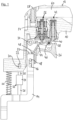
- the pneumatic nailer from which in Figure 1 Only a section is shown, has a compressed air connection and a working cylinder in which a working piston connected to a driving plunger is slidably guided.
- the working cylinder is closed at the top by a main valve, which has a pilot control valve is controlled.
- a main valve which has a pilot control valve is controlled.
- FIG. 1 On the other hand, a section of a housing 10, which also forms a section of the handle 12, is clearly visible.
- a placement sensor 14 is guided on the housing 10 so as to be displaceable in the vertical direction, with an in Figure 1
- the pneumatic nailer is not attached to a workpiece.
- the attachment sensor 14 At its upper end, the attachment sensor 14 has an elongated hole 16 in which a pin 18 attached to the housing 10 is arranged. From the position of this pin 18 in the elongated hole 16, it is clearly visible in all figures in which position the attachment sensor 14 is currently located.
- a spring 20 is arranged between the housing 10 and the attachment sensor 14, which presses the attachment sensor 14 downwards.
- a damper 22 is arranged between the housing 10 and the attachment sensor 14, which in the example shown is a cylindrical damper housing 24, in which a damper tappet 26 is slidably guided.
- the damper plunger 26 protrudes from the lower end of the damper housing 24 and is attached to the attachment sensor 14 at its free end.
- the damper 22 has a fastening section 28 which is firmly connected to the damper housing 24.
- the upper, free end of this fastening section 28 is articulated with a horizontally arranged pin 30 on an elongated hole 32 formed in the housing 10.
- the length of the elongated hole 32 is smaller than the length of the elongated hole 16, in the example about half as large.
- the damper 22 is designed so that it dampens a movement of the damper tappet 26 downwards, i.e. out of the damper housing 24, but not a movement in the opposite direction, i.e. into the damper housing 24.
- the interaction of the spring 20 with the damper 22 determines the speed at which the placement sensor 14 moves downward again when the pin 30 rests on the lower end of the elongated hole 32 and for the further downward movement of the damper plunger 26 must be pulled out of the damper housing 24.
- a triggering device of the pneumatic nailer includes a trigger 36 which is pivotally mounted at its front end about a horizontal axis 34.
- the trigger 36 has an actuating surface 38 for actuating a valve pin 40 of a trigger valve 42.
- the triggering device comprises a force transmission element in the form of a lever 44, which is pivotally mounted at its rear end about an axis 46 arranged horizontally and fixed to the housing. The free end 48 of the lever 44 rests on an upper surface 50 of the attachment sensor 14.
- An actuating surface 52 arranged on the top of the lever 44 serves to actuate a control valve member 54 of a control valve 56 designed as a valve pin.
- a main control line 58 is supplied with compressed air from a ventilated housing interior 60 via the trigger valve 42 and the control valve 56.
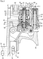
- FIG. 2 shows an enlarged section Fig. 1 .
- the attachment sensor 14 is still in its lower end position and the trigger 36 is not activated.
- the control valve member 54 which can be moved along an adjustment path, is also in a lower end position, which corresponds to a completely unactuated position of the control valve 56.
- the valve pin 40 of the trigger valve 42 is also unactuated. It has a lower O-ring 62 that is not in sealing and an upper O-ring 64 that is in sealing.
- a transverse bore 66 which is located in a sleeve 68 of the trigger valve 42, is connected to outside air via an annular gap 70 and past the lower O-ring 62.
- the ventilated housing interior 60 is blocked off from the transverse bore 66 and the line 72 by the upper O-ring 64 located in the seal.
- the control valve member 54 is movably guided in a two-part sleeve with an inner sleeve part 74 and an outer sleeve part 76 which is fixed to the housing.
- the outer sleeve part 76 is surrounded by a safety actuator 78, which is also sleeve-shaped.
- the safety actuator 78 is accommodated in the housing 10 in a vertically displaceable manner. It is from a spring 80 in its in the Fig. 2 shown, upper end position pressed, which corresponds to a ready-to-release state of the pneumatic nailer.
- the safety actuator 54 has four O-rings: A first O-ring 82 seals against the inner sleeve part 74 in every position of the control valve member 54. Between a second O-ring 84 and a third O-ring 86, both of which are not in a seal, a transverse bore 88 ends in the control valve member 54, which has a longitudinal bore 90 in the control valve member 54 and a further transverse bore 92 in the control valve member 54 connected to outside air. A fourth O-ring 94 is located in Fig. 2 in poetry. The control valve member 54 is pressed into its lower end position by a spring 96.
- a control chamber 98 is arranged below the safety actuator 78.
- a pressure prevailing in this control chamber 98 exerts an upward force on the safety actuator 78.
- the control chamber 98 is connected to outside air via a transverse bore 100 in the outer sleeve part 76 and a transverse bore 102 in the inner sleeve part 74 past the second O-ring 84 via the bores 88, 90, 92 in the safety actuator 54.
- the main control line 58 is also vented, namely via a transverse bore 104 in the safety actuator 78, past an O-ring 106 which is not in a seal and which is arranged between the outer sleeve part 76 and the safety actuator 78, a transverse bore 108 in the outer sleeve part 76 and past the third O-ring 86 through the bores 88, 90, 92 in the control valve member 54.
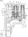
- the upper surface 50 of the attachment sensor 14 has taken the free end 48 of the lever 44 with it, so that the actuating surface 52 has shifted the control valve member 54 to its fully actuated position.
- the second O-ring 84 and the third O-ring 86 are now sealed, so that between the bores 88, 90, 92 (see Fig. 2 ) there is no longer any connection in the control valve member 54 and the transverse bore 108, 104 and the annular gap between them.
- the fourth O-ring 94 has moved out of the seal, so that the line 72 is now connected to the main control line 58 via the transverse bore 108. Since the line 72 is still connected to outside air via the trigger valve 42, this does not yet trigger a driving process.
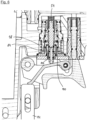
- Fig. 4 position shown.
- the valve pin 40 has been moved upward and is now in a fully actuated position in which the lower O-ring 62 is in seal and the upper O-ring 64 has moved out of the seal.
- the line 72 is ventilated past the upper O-ring 64 via the bore 66 from the housing interior 60.
- the control chamber 98 is also ventilated, namely from the line 72 past the fourth O-ring 94, through a transverse bore 110 in the outer sleeve part 76, which forms a check valve with a further O-ring 112, and through an annular gap 114 between the external one Sleeve part 76 and the safety actuator 78.
- the force exerted on the safety actuator 78 by the pressure in the control chamber 98 and the spring 80 is so great that it outweighs the force exerted by the pressure in the space 116 above the safety actuator 78, so that the safety actuator 78 initially remains in its upper end position.
- This upper end position of the safety actuator 78 can also be referred to as the release position.
- the pneumatic nailer After lifting the pneumatic nailer from the workpiece, the pneumatic nailer gets into the in very quickly Fig. 5 Position shown, in which the attachment sensor 14 has already moved a little downwards, until the pin 30 rests on the lower end of the elongated hole 32 and the effect of the damper 22 begins.
- the downward movement of the placement sensor 14 is coupled via the lever 44 to a downward movement of the control valve member 54 because the control valve member 54 is on the actuating surface 52 of the lever 44 due to the force exerted by the spring 96 and the free end 48 of the lever 44 is at the upper end 50 of the Attachment sensor 14 is present.
- the placement sensor 14 continues its downward movement from that corresponding to the second switching point of the control valve member 54, in which Fig. 5 Position shown slows down under the influence of the damper 22. After a predetermined period of time has elapsed, which can be between 1 second and 5 seconds, for example, it reaches the in Fig. 6 position shown, which is slightly above its completely unactuated position Fig. 2 lies.
- Figure 7 shows the condition of the pneumatic nailer again a short time later.
- the placement sensor 14 has reached its completely unactuated position and the control valve member 54 has exceeded the first switching point, so that the control chamber 98 is connected to outside air and no longer exerts any force on the safety actuator 78.
- the force exerted on the safety actuator 78 by the pressure in the space 116 then outweighs the force of the spring 80, so that the safety actuator 78 has shifted to its lower end position.
- This lower end position is a safety position in which no further driving processes can be triggered, in particular not by contact triggering by placing the pneumatic nailer again on a workpiece.
- the pneumatic nailer is therefore in a locked state.
- the main control line 58 can no longer be ventilated because the transverse bore 104 passes through the O-ring 106, which is now in a seal, and the two O-rings 118, which are always in a seal and 120 is closed.
- the O-rings 122, 124 are no longer sealed. Between these O-rings 122, 124 there is a hole, not shown, which additionally connects the control chamber 98 and the main control line 58 with outside air.
- FIG. 7 shows Fig. 7 at the same time the state of the pneumatic nailer, which occurs when the trigger 36 is actuated before the attachment sensor 14 is actuated.
- the safety actuator 78 is displaced into its safety position by the pressure built up in the space 116, while the control chamber 98 remains connected to outside air. That is why, with the pneumatic nailer explained as an example, a first driving process must always be carried out individually.
Landscapes
- Engineering & Computer Science (AREA)
- Mechanical Engineering (AREA)
- Physics & Mathematics (AREA)
- Fluid Mechanics (AREA)
- Portable Nailing Machines And Staplers (AREA)
Claims (14)
- Cloueuse pneumatique dotée• d'un piston de travail qui est relié à un poussoir d'enfoncement destiné à enfoncer un moyen de fixation et qui est alimenté en air comprimé lors du déclenchement d'une opération d'enfoncement, et• d'un dispositif de déclenchement pour déclencher une opération d'enfoncement,• un dispositif de sécurité commandé par une pression dans une chambre de commande (98) qui est conçu pour faire passer la cloueuse pneumatique d'un état prêt à déclencher à un état verrouillé, et• une soupape de commande (56) destinée à commander la pression dans la chambre de commande (98), la soupape de commande (56) comportant un élément de soupape de commande (54) mobile le long d'un trajet de déplacement,• caractérisée par un amortisseur (22) couplé à l'élément de soupape de commande (54).
- Cloueuse pneumatique selon la revendication 1, caractérisée en ce que l'amortisseur (22) est couplé à l'élément de soupape de commande (54) de sorte à ralentir un mouvement de l'élément de soupape de commande (54) au moins le long d'une partie du trajet de déplacement.
- Cloueuse pneumatique selon la revendication 1 ou 2, caractérisée en ce que le dispositif de déclenchement présente un capteur de pose (14) qui est conçu pour déplacer l'élément de soupape de commande (54) dans une position entièrement actionnée lorsque la cloueuse pneumatique est posée sur une pièce à usiner.
- Cloueuse pneumatique selon la revendication 3, caractérisée en ce que l'élément de soupape de commande (54) présente un premier point de commutation au niveau duquel la chambre de commande (98) est ventilée ou purgée par la soupape de commande (56) et que l'amortisseur (22) est couplé à l'élément de soupape de commande (54) de telle sorte qu'après le retrait de la cloueuse pneumatique d'une pièce à usiner, l'élément de soupape de commande (54) atteint le premier point de commutation à partir de la position complètement actionnée après l'écoulement d'une durée prédéfinie.
- Cloueuse pneumatique selon la revendication 3 ou 4, caractérisée en ce que la cloueuse pneumatique comporte une ligne de commande principale (58) qui doit être ventilée pour déclencher un processus d'enfoncement et l'élément de soupape de commande (54) présente un deuxième point de commutation au niveau duquel la ligne de commande principale (56) est purgée par la soupape de commande (56).
- Cloueuse pneumatique selon la revendication 3 ou 4, caractérisée en ce que la cloueuse pneumatique comporte une ligne de commande principale (58) qui doit être purgée pour déclencher un processus d'enfoncement et l'élément de soupape de commande (54) présente un deuxième point de commutation au niveau duquel la ligne de commande principale (58) est ventilée par la soupape de commande (56).
- Cloueuse pneumatique selon la revendication 5 ou 6, caractérisée en ce que l'amortisseur est conçu et couplé à l'élément de soupape de commande (54) de sorte à ne pas amortir un mouvement de l'élément de soupape de commande (54) de la position complètement actionnée jusqu'au deuxième point de commutation.
- Cloueuse pneumatique selon l'une des revendications 1 à 7, caractérisée en ce qu'une fixation de l'amortisseur (22) présente un trou oblong (32) de sorte qu'un mouvement relatif de deux composants reliés par l' amortisseur (22) sur une partie d'une plage de déplacement possible n'est pas amorti par l'amortisseur (22).
- Cloueuse pneumatique selon l'une des revendications 1 à 8, caractérisée en ce qu'un effet d'amortissement de l'amortisseur (22) est limité à l'une des deux directions de déplacement possibles de l'amortisseur (22).
- Cloueuse pneumatique selon l'une des revendications 1 à 9, caractérisée en ce que l'amortisseur (22) présente deux éléments mobiles l'un par rapport à l'autre dont il amortit le mouvement relatif, l'un des deux éléments étant fixé et/ou articulé sur une partie solidaire du boîtier de la cloueuse pneumatique et l'autre des deux éléments étant conçu, fixé et/ou articulé sur le capteur de pose (14), l'élément de soupape de commande (54) ou un dispositif de transmission de force qui est conçu pour transmettre une force du capteur de pose (14) à l'élément de soupape de commande (54).
- Cloueuse pneumatique selon l'une des revendications 1 à 10, caractérisée en ce que l'amortisseur (22) est un amortisseur linéaire ou un amortisseur rotatif.
- Cloueuse pneumatique selon l'une des revendications 1 à 11, caractérisée en ce que l'amortisseur (22) est un amortisseur par fluide ou un amortisseur à friction.
- Cloueuse pneumatique selon l'une des revendications 1 à 12, caractérisée en ce que le dispositif de sécurité présente un actionneur de sécurité (78) qui peut être déplacé entre une position de déclenchement dans laquelle une action sur le dispositif de déclenchement peut déclencher un processus d'enfoncement et une position de sécurité dans laquelle une action sur le dispositif de déclenchement ne peut déclencher aucun processus d'enfoncement, la pression dans la chambre de commande (98) exerçant une force sur l'actionneur de sécurité (78).
- Cloueuse pneumatique selon la revendication 13, caractérisée en ce que l'actionneur de sécurité (78) est déplacé de la position de déclenchement vers la position de sécurité lorsque la pression dans la chambre de commande (78) dépasse un seuil de pression prédéfini.
Priority Applications (3)
| Application Number | Priority Date | Filing Date | Title |
|---|---|---|---|
| EP18212051.9A EP3666469B1 (fr) | 2018-12-12 | 2018-12-12 | Cloueur pneumatique doté d'un dispositif de sécurité |
| AU2019279911A AU2019279911A1 (en) | 2018-12-12 | 2019-12-09 | Pneumatic nailer with a safety device |
| US16/712,491 US11364609B2 (en) | 2018-12-12 | 2019-12-12 | Pneumatic nailer with a safety device |
Applications Claiming Priority (1)
| Application Number | Priority Date | Filing Date | Title |
|---|---|---|---|
| EP18212051.9A EP3666469B1 (fr) | 2018-12-12 | 2018-12-12 | Cloueur pneumatique doté d'un dispositif de sécurité |
Publications (2)
| Publication Number | Publication Date |
|---|---|
| EP3666469A1 EP3666469A1 (fr) | 2020-06-17 |
| EP3666469B1 true EP3666469B1 (fr) | 2024-03-27 |
Family
ID=64665177
Family Applications (1)
| Application Number | Title | Priority Date | Filing Date |
|---|---|---|---|
| EP18212051.9A Active EP3666469B1 (fr) | 2018-12-12 | 2018-12-12 | Cloueur pneumatique doté d'un dispositif de sécurité |
Country Status (3)
| Country | Link |
|---|---|
| US (1) | US11364609B2 (fr) |
| EP (1) | EP3666469B1 (fr) |
| AU (1) | AU2019279911A1 (fr) |
Families Citing this family (4)
| Publication number | Priority date | Publication date | Assignee | Title |
|---|---|---|---|---|
| JP6575679B2 (ja) * | 2016-04-28 | 2019-09-18 | 工機ホールディングス株式会社 | 打込機 |
| EP3479963B1 (fr) * | 2017-11-01 | 2020-12-09 | Joh. Friedrich Behrens AG | Cloueur à air comprimé pourvu d'un système de soupape de sécurité |
| JP7222305B2 (ja) * | 2019-04-26 | 2023-02-15 | マックス株式会社 | 空気圧工具 |
| US11618146B2 (en) * | 2020-12-21 | 2023-04-04 | Zhejiang Rongpeng Air Tools Co., Ltd. | Safety structure used in the anti-auto-firing device of electric nail guns |
Family Cites Families (10)
| Publication number | Priority date | Publication date | Assignee | Title |
|---|---|---|---|---|
| US3964659A (en) | 1975-03-12 | 1976-06-22 | Senco Products, Inc. | Safety firing control means for a fluid operated tool |
| US5522532A (en) * | 1995-03-14 | 1996-06-04 | Testo Industry Corp. | Single-shooting/continuous-shooting control switch for penumatic nail guns |
| ES2618859T3 (es) * | 2013-02-19 | 2017-06-22 | Joh. Friedrich Behrens Ag | Clavadora neumática con un disparador accionable manualmente y un sensor de contacto |
| DE102013106657A1 (de) | 2013-06-25 | 2015-01-08 | Illinois Tool Works Inc. | Eintreibwerkzeug zum Eintreiben von Befestigungsmitteln in ein Werkstück |
| US9662776B2 (en) | 2013-12-17 | 2017-05-30 | Illinois Tool Works Inc. | Fastener-driving tool including a reversion trigger with a damper |
| CN105789148A (zh) | 2014-12-25 | 2016-07-20 | 讯芯电子科技(中山)有限公司 | 滤波器封装结构及滤波器封装结构的制作方法 |
| JP6408944B2 (ja) * | 2015-03-24 | 2018-10-17 | 株式会社マキタ | 打ち込み工具 |
| ES2704139T3 (es) | 2016-06-15 | 2019-03-14 | Behrens Ag Friedrich Joh | Remachadora de aire comprimido con cámara de control de seguridad |
| JP6824781B2 (ja) * | 2017-03-01 | 2021-02-03 | 株式会社マキタ | 打ち込み工具 |
| JP6833565B2 (ja) * | 2017-03-01 | 2021-02-24 | 株式会社マキタ | 打ち込み工具 |
-
2018
- 2018-12-12 EP EP18212051.9A patent/EP3666469B1/fr active Active
-
2019
- 2019-12-09 AU AU2019279911A patent/AU2019279911A1/en active Pending
- 2019-12-12 US US16/712,491 patent/US11364609B2/en active Active
Also Published As
| Publication number | Publication date |
|---|---|
| EP3666469A1 (fr) | 2020-06-17 |
| US11364609B2 (en) | 2022-06-21 |
| US20200189078A1 (en) | 2020-06-18 |
| AU2019279911A1 (en) | 2020-07-02 |
Similar Documents
| Publication | Publication Date | Title |
|---|---|---|
| EP3666469B1 (fr) | Cloueur pneumatique doté d'un dispositif de sécurité | |
| EP2767365B1 (fr) | Cloueur à air comprimé avec déclencheur manuel et capteur de contact | |
| EP3446833B1 (fr) | Cloueur à air comprimé pourvu de dispositif de soupape de sécurité | |
| EP3257633B1 (fr) | Cloueur a air comprime comprenant une chambre de commande de securite | |
| DE1703110C3 (de) | Druckluftwerkzeug, insbesondere Druckluftnagler | |
| DE3014803C2 (de) | Druckluftnagler | |
| DE3142237A1 (de) | Pneumatisch betaetigbares befestigungsmitteleintreibgeraet | |
| DE2011890C3 (de) | Auslösesicherung an einem Preßluftnag ler | |
| EP3697573B1 (fr) | Clouseuse à air comprimé pourvue d'un actionneur de sécurité | |
| EP3471921B1 (fr) | Cloueur a air comprime comprenant un declenchement sequentiel et par contact | |
| EP3703911B1 (fr) | Cloueur à air comprimé pourvu d'un système de soupape de sécurité | |
| EP3509797B1 (fr) | Cloueuse pneumatique à mode automatique et comprenant un capteur de contact | |
| DE2718942C3 (de) | Auslösesicherung an einem Druckluftnagler | |
| DE4032231C2 (fr) | ||
| DE202013001537U1 (de) | Druckluftnagler mit einem handbetätigbaren Auslöser und einem Aufsetzfühler | |
| DE3100703C2 (de) | Sicherheitsvorrichtung für einen pneumatisch oder elektrisch betriebenen Nagler | |
| DE19804456C1 (de) | Auslösegesichertes Eintreibgerät für Befestigungsmittel | |
| EP3760379B1 (fr) | Cloueur pneumatique doté d'un dispositif de sécurité | |
| EP1650050B1 (fr) | Ensemble pour l'alimentation d'air sous pression à un dispositif d'estampage | |
| DE202018105352U1 (de) | Sicherheitsvorschaltgerät für ein druckluftbetriebenes Gerät | |
| DE2524780C3 (de) | Überwachungs- und Sicherheitseinrichtung für eine zweihandbetätigte Steuereinrichtung | |
| DE1902196A1 (de) | Druckgetriebenes Werkzeug | |
| DE102004057229B4 (de) | Prägevorrichtung mit Druckluftantrieb | |
| DE2223684B2 (de) | Druckluftnagler mit Auslösesperre | |
| DE2037815B2 (de) | Ventileinrichtung für den Arbeitshubraum eines Druckluftnaglers |
Legal Events
| Date | Code | Title | Description |
|---|---|---|---|
| PUAI | Public reference made under article 153(3) epc to a published international application that has entered the european phase |
Free format text: ORIGINAL CODE: 0009012 |
|
| STAA | Information on the status of an ep patent application or granted ep patent |
Free format text: STATUS: THE APPLICATION HAS BEEN PUBLISHED |
|
| AK | Designated contracting states |
Kind code of ref document: A1 Designated state(s): AL AT BE BG CH CY CZ DE DK EE ES FI FR GB GR HR HU IE IS IT LI LT LU LV MC MK MT NL NO PL PT RO RS SE SI SK SM TR |
|
| AX | Request for extension of the european patent |
Extension state: BA ME |
|
| STAA | Information on the status of an ep patent application or granted ep patent |
Free format text: STATUS: REQUEST FOR EXAMINATION WAS MADE |
|
| 17P | Request for examination filed |
Effective date: 20201207 |
|
| RBV | Designated contracting states (corrected) |
Designated state(s): AL AT BE BG CH CY CZ DE DK EE ES FI FR GB GR HR HU IE IS IT LI LT LU LV MC MK MT NL NO PL PT RO RS SE SI SK SM TR |
|
| RAP1 | Party data changed (applicant data changed or rights of an application transferred) |
Owner name: BEA GMBH |
|
| P01 | Opt-out of the competence of the unified patent court (upc) registered |
Effective date: 20230515 |
|
| GRAP | Despatch of communication of intention to grant a patent |
Free format text: ORIGINAL CODE: EPIDOSNIGR1 |
|
| STAA | Information on the status of an ep patent application or granted ep patent |
Free format text: STATUS: GRANT OF PATENT IS INTENDED |
|
| INTG | Intention to grant announced |
Effective date: 20231009 |
|
| GRAS | Grant fee paid |
Free format text: ORIGINAL CODE: EPIDOSNIGR3 |
|
| GRAA | (expected) grant |
Free format text: ORIGINAL CODE: 0009210 |
|
| STAA | Information on the status of an ep patent application or granted ep patent |
Free format text: STATUS: THE PATENT HAS BEEN GRANTED |
|
| AK | Designated contracting states |
Kind code of ref document: B1 Designated state(s): AL AT BE BG CH CY CZ DE DK EE ES FI FR GB GR HR HU IE IS IT LI LT LU LV MC MK MT NL NO PL PT RO RS SE SI SK SM TR |
|
| REG | Reference to a national code |
Ref country code: GB Ref legal event code: FG4D Free format text: NOT ENGLISH |
|
| REG | Reference to a national code |
Ref country code: CH Ref legal event code: EP |
|
| REG | Reference to a national code |
Ref country code: DE Ref legal event code: R096 Ref document number: 502018014313 Country of ref document: DE |
|
| REG | Reference to a national code |
Ref country code: IE Ref legal event code: FG4D Free format text: LANGUAGE OF EP DOCUMENT: GERMAN |
|
| REG | Reference to a national code |
Ref country code: SE Ref legal event code: TRGR |