EP3666328B1 - Treating a tumor or the like with electric fields at different orientations - Google Patents
Treating a tumor or the like with electric fields at different orientations Download PDFInfo
- Publication number
- EP3666328B1 EP3666328B1 EP20152897.3A EP20152897A EP3666328B1 EP 3666328 B1 EP3666328 B1 EP 3666328B1 EP 20152897 A EP20152897 A EP 20152897A EP 3666328 B1 EP3666328 B1 EP 3666328B1
- Authority
- EP
- European Patent Office
- Prior art keywords
- electrodes
- field
- cells
- electric field
- cell
- Prior art date
- Legal status (The legal status is an assumption and is not a legal conclusion. Google has not performed a legal analysis and makes no representation as to the accuracy of the status listed.)
- Active
Links
- 230000005684 electric field Effects 0.000 title claims description 134
- 206010028980 Neoplasm Diseases 0.000 title description 82
- 230000006378 damage Effects 0.000 claims description 36
- 230000032823 cell division Effects 0.000 claims description 12
- 239000011248 coating agent Substances 0.000 claims description 8
- 238000000576 coating method Methods 0.000 claims description 8
- 230000010363 phase shift Effects 0.000 claims description 8
- 230000012010 growth Effects 0.000 claims description 7
- 238000003491 array Methods 0.000 claims description 4
- 230000001360 synchronised effect Effects 0.000 claims description 3
- 230000002401 inhibitory effect Effects 0.000 claims description 2
- 238000005259 measurement Methods 0.000 claims 1
- 210000004027 cell Anatomy 0.000 description 217
- 210000001519 tissue Anatomy 0.000 description 77
- 239000004020 conductor Substances 0.000 description 61
- 238000011282 treatment Methods 0.000 description 50
- 230000000694 effects Effects 0.000 description 36
- 239000000499 gel Substances 0.000 description 33
- 239000012528 membrane Substances 0.000 description 33
- 239000000463 material Substances 0.000 description 32
- 238000000034 method Methods 0.000 description 32
- 230000007246 mechanism Effects 0.000 description 22
- 230000035755 proliferation Effects 0.000 description 22
- 230000008569 process Effects 0.000 description 19
- 238000009826 distribution Methods 0.000 description 18
- 210000004881 tumor cell Anatomy 0.000 description 18
- 208000032612 Glial tumor Diseases 0.000 description 16
- 206010018338 Glioma Diseases 0.000 description 16
- 230000015556 catabolic process Effects 0.000 description 16
- 210000000170 cell membrane Anatomy 0.000 description 14
- 238000010438 heat treatment Methods 0.000 description 14
- 230000006870 function Effects 0.000 description 13
- 201000001441 melanoma Diseases 0.000 description 13
- 239000000523 sample Substances 0.000 description 13
- 238000002474 experimental method Methods 0.000 description 12
- 230000001965 increasing effect Effects 0.000 description 12
- 210000000056 organ Anatomy 0.000 description 12
- 210000003463 organelle Anatomy 0.000 description 12
- 238000009413 insulation Methods 0.000 description 11
- 150000002500 ions Chemical class 0.000 description 11
- 239000000853 adhesive Substances 0.000 description 10
- 210000000481 breast Anatomy 0.000 description 9
- 239000003990 capacitor Substances 0.000 description 9
- 210000000805 cytoplasm Anatomy 0.000 description 9
- 230000001070 adhesive effect Effects 0.000 description 8
- 230000015572 biosynthetic process Effects 0.000 description 8
- 230000004663 cell proliferation Effects 0.000 description 8
- 210000000349 chromosome Anatomy 0.000 description 8
- 230000001419 dependent effect Effects 0.000 description 8
- 210000003722 extracellular fluid Anatomy 0.000 description 8
- 201000011510 cancer Diseases 0.000 description 7
- 238000009422 external insulation Methods 0.000 description 7
- 239000012212 insulator Substances 0.000 description 7
- 238000009421 internal insulation Methods 0.000 description 7
- 210000005061 intracellular organelle Anatomy 0.000 description 7
- 230000004936 stimulating effect Effects 0.000 description 7
- 241000894006 Bacteria Species 0.000 description 6
- GWEVSGVZZGPLCZ-UHFFFAOYSA-N Titan oxide Chemical compound O=[Ti]=O GWEVSGVZZGPLCZ-UHFFFAOYSA-N 0.000 description 6
- 238000013459 approach Methods 0.000 description 6
- 230000008901 benefit Effects 0.000 description 6
- 230000007423 decrease Effects 0.000 description 6
- 238000001727 in vivo Methods 0.000 description 6
- 230000002147 killing effect Effects 0.000 description 6
- 230000003902 lesion Effects 0.000 description 6
- 229920002521 macromolecule Polymers 0.000 description 6
- 230000001681 protective effect Effects 0.000 description 6
- 238000010276 construction Methods 0.000 description 5
- 239000013078 crystal Substances 0.000 description 5
- 230000005764 inhibitory process Effects 0.000 description 5
- 239000011810 insulating material Substances 0.000 description 5
- 230000005855 radiation Effects 0.000 description 5
- 230000009467 reduction Effects 0.000 description 5
- 238000010408 sweeping Methods 0.000 description 5
- 238000012404 In vitro experiment Methods 0.000 description 4
- 102000029749 Microtubule Human genes 0.000 description 4
- 108091022875 Microtubule Proteins 0.000 description 4
- 230000031016 anaphase Effects 0.000 description 4
- 210000004718 centriole Anatomy 0.000 description 4
- 239000003795 chemical substances by application Substances 0.000 description 4
- 238000002512 chemotherapy Methods 0.000 description 4
- 238000003776 cleavage reaction Methods 0.000 description 4
- 239000007822 coupling agent Substances 0.000 description 4
- 230000021953 cytokinesis Effects 0.000 description 4
- 238000010586 diagram Methods 0.000 description 4
- 238000006073 displacement reaction Methods 0.000 description 4
- 238000005868 electrolysis reaction Methods 0.000 description 4
- 238000007917 intracranial administration Methods 0.000 description 4
- 230000003211 malignant effect Effects 0.000 description 4
- 229910052751 metal Inorganic materials 0.000 description 4
- 239000002184 metal Substances 0.000 description 4
- 210000004688 microtubule Anatomy 0.000 description 4
- 210000004940 nucleus Anatomy 0.000 description 4
- 230000007017 scission Effects 0.000 description 4
- 230000035945 sensitivity Effects 0.000 description 4
- 208000026310 Breast neoplasm Diseases 0.000 description 3
- -1 Ca++ ions Chemical class 0.000 description 3
- 108091060290 Chromatid Proteins 0.000 description 3
- 241000195493 Cryptophyta Species 0.000 description 3
- 241000233866 Fungi Species 0.000 description 3
- 206010058467 Lung neoplasm malignant Diseases 0.000 description 3
- 241000699666 Mus <mouse, genus> Species 0.000 description 3
- 210000003169 central nervous system Anatomy 0.000 description 3
- 230000008859 change Effects 0.000 description 3
- 210000004756 chromatid Anatomy 0.000 description 3
- 230000000295 complement effect Effects 0.000 description 3
- 238000007796 conventional method Methods 0.000 description 3
- 230000001351 cycling effect Effects 0.000 description 3
- 239000007933 dermal patch Substances 0.000 description 3
- 238000010291 electrical method Methods 0.000 description 3
- 238000004520 electroporation Methods 0.000 description 3
- 239000004744 fabric Substances 0.000 description 3
- 239000000835 fiber Substances 0.000 description 3
- 238000007667 floating Methods 0.000 description 3
- 210000003205 muscle Anatomy 0.000 description 3
- 230000037361 pathway Effects 0.000 description 3
- 230000000149 penetrating effect Effects 0.000 description 3
- 239000004033 plastic Substances 0.000 description 3
- 229920003023 plastic Polymers 0.000 description 3
- 230000031877 prophase Effects 0.000 description 3
- 238000001959 radiotherapy Methods 0.000 description 3
- 230000000638 stimulation Effects 0.000 description 3
- 230000016853 telophase Effects 0.000 description 3
- 206010006187 Breast cancer Diseases 0.000 description 2
- 201000009030 Carcinoma Diseases 0.000 description 2
- 241000196324 Embryophyta Species 0.000 description 2
- 206010061218 Inflammation Diseases 0.000 description 2
- 241001465754 Metazoa Species 0.000 description 2
- 241000204031 Mycoplasma Species 0.000 description 2
- 206010029098 Neoplasm skin Diseases 0.000 description 2
- 240000004808 Saccharomyces cerevisiae Species 0.000 description 2
- 208000000453 Skin Neoplasms Diseases 0.000 description 2
- 238000002679 ablation Methods 0.000 description 2
- 208000009956 adenocarcinoma Diseases 0.000 description 2
- 210000004102 animal cell Anatomy 0.000 description 2
- 239000002246 antineoplastic agent Substances 0.000 description 2
- 229910002113 barium titanate Inorganic materials 0.000 description 2
- 230000000747 cardiac effect Effects 0.000 description 2
- 230000001413 cellular effect Effects 0.000 description 2
- 239000000919 ceramic Substances 0.000 description 2
- 229940127089 cytotoxic agent Drugs 0.000 description 2
- 230000003247 decreasing effect Effects 0.000 description 2
- 238000011161 development Methods 0.000 description 2
- 208000037265 diseases, disorders, signs and symptoms Diseases 0.000 description 2
- 208000035475 disorder Diseases 0.000 description 2
- 239000013013 elastic material Substances 0.000 description 2
- 239000003792 electrolyte Substances 0.000 description 2
- 210000003527 eukaryotic cell Anatomy 0.000 description 2
- 230000005294 ferromagnetic effect Effects 0.000 description 2
- PCHJSUWPFVWCPO-UHFFFAOYSA-N gold Chemical compound [Au] PCHJSUWPFVWCPO-UHFFFAOYSA-N 0.000 description 2
- 239000010931 gold Substances 0.000 description 2
- 229910052737 gold Inorganic materials 0.000 description 2
- 239000000017 hydrogel Substances 0.000 description 2
- 230000001939 inductive effect Effects 0.000 description 2
- 230000004054 inflammatory process Effects 0.000 description 2
- 230000016507 interphase Effects 0.000 description 2
- 230000003834 intracellular effect Effects 0.000 description 2
- 210000002977 intracellular fluid Anatomy 0.000 description 2
- 239000007788 liquid Substances 0.000 description 2
- GQYHUHYESMUTHG-UHFFFAOYSA-N lithium niobate Chemical compound [Li+].[O-][Nb](=O)=O GQYHUHYESMUTHG-UHFFFAOYSA-N 0.000 description 2
- 201000005202 lung cancer Diseases 0.000 description 2
- 208000020816 lung neoplasm Diseases 0.000 description 2
- 244000005700 microbiome Species 0.000 description 2
- 230000011278 mitosis Effects 0.000 description 2
- 210000005036 nerve Anatomy 0.000 description 2
- 230000003287 optical effect Effects 0.000 description 2
- 230000036961 partial effect Effects 0.000 description 2
- 230000037368 penetrate the skin Effects 0.000 description 2
- 230000000737 periodic effect Effects 0.000 description 2
- 230000010076 replication Effects 0.000 description 2
- 230000004044 response Effects 0.000 description 2
- 208000037803 restenosis Diseases 0.000 description 2
- 230000000717 retained effect Effects 0.000 description 2
- 231100000241 scar Toxicity 0.000 description 2
- 238000000926 separation method Methods 0.000 description 2
- 238000007493 shaping process Methods 0.000 description 2
- 238000001356 surgical procedure Methods 0.000 description 2
- 210000001550 testis Anatomy 0.000 description 2
- 239000004408 titanium dioxide Substances 0.000 description 2
- 238000012546 transfer Methods 0.000 description 2
- 230000001052 transient effect Effects 0.000 description 2
- 230000004614 tumor growth Effects 0.000 description 2
- 210000003708 urethra Anatomy 0.000 description 2
- 210000001215 vagina Anatomy 0.000 description 2
- 230000002792 vascular Effects 0.000 description 2
- WSMQKESQZFQMFW-UHFFFAOYSA-N 5-methyl-pyrazole-3-carboxylic acid Chemical compound CC1=CC(C(O)=O)=NN1 WSMQKESQZFQMFW-UHFFFAOYSA-N 0.000 description 1
- 229920001817 Agar Polymers 0.000 description 1
- 201000003076 Angiosarcoma Diseases 0.000 description 1
- 206010003571 Astrocytoma Diseases 0.000 description 1
- 206010004146 Basal cell carcinoma Diseases 0.000 description 1
- 206010004446 Benign prostatic hyperplasia Diseases 0.000 description 1
- 206010004593 Bile duct cancer Diseases 0.000 description 1
- 206010005003 Bladder cancer Diseases 0.000 description 1
- 208000003174 Brain Neoplasms Diseases 0.000 description 1
- 206010006784 Burning sensation Diseases 0.000 description 1
- 229910002966 CaCu3Ti4O12 Inorganic materials 0.000 description 1
- 206010008342 Cervix carcinoma Diseases 0.000 description 1
- 208000005243 Chondrosarcoma Diseases 0.000 description 1
- 201000009047 Chordoma Diseases 0.000 description 1
- 208000006332 Choriocarcinoma Diseases 0.000 description 1
- 208000032544 Cicatrix Diseases 0.000 description 1
- 206010009944 Colon cancer Diseases 0.000 description 1
- 229920000742 Cotton Polymers 0.000 description 1
- 208000009798 Craniopharyngioma Diseases 0.000 description 1
- 208000002699 Digestive System Neoplasms Diseases 0.000 description 1
- 201000009051 Embryonal Carcinoma Diseases 0.000 description 1
- 206010014967 Ependymoma Diseases 0.000 description 1
- 208000006168 Ewing Sarcoma Diseases 0.000 description 1
- 201000008808 Fibrosarcoma Diseases 0.000 description 1
- 108010010803 Gelatin Proteins 0.000 description 1
- 208000001258 Hemangiosarcoma Diseases 0.000 description 1
- 208000018142 Leiomyosarcoma Diseases 0.000 description 1
- 229910003327 LiNbO3 Inorganic materials 0.000 description 1
- 206010025323 Lymphomas Diseases 0.000 description 1
- 208000007054 Medullary Carcinoma Diseases 0.000 description 1
- 208000000172 Medulloblastoma Diseases 0.000 description 1
- 206010027406 Mesothelioma Diseases 0.000 description 1
- 206010027476 Metastases Diseases 0.000 description 1
- 241000699670 Mus sp. Species 0.000 description 1
- 206010029260 Neuroblastoma Diseases 0.000 description 1
- 239000004677 Nylon Substances 0.000 description 1
- 201000010133 Oligodendroglioma Diseases 0.000 description 1
- 241000283973 Oryctolagus cuniculus Species 0.000 description 1
- 206010033128 Ovarian cancer Diseases 0.000 description 1
- 206010061535 Ovarian neoplasm Diseases 0.000 description 1
- 206010061902 Pancreatic neoplasm Diseases 0.000 description 1
- 208000007641 Pinealoma Diseases 0.000 description 1
- 206010035226 Plasma cell myeloma Diseases 0.000 description 1
- 208000007452 Plasmacytoma Diseases 0.000 description 1
- ZLMJMSJWJFRBEC-UHFFFAOYSA-N Potassium Chemical compound [K] ZLMJMSJWJFRBEC-UHFFFAOYSA-N 0.000 description 1
- 208000006994 Precancerous Conditions Diseases 0.000 description 1
- 206010060862 Prostate cancer Diseases 0.000 description 1
- 208000004403 Prostatic Hyperplasia Diseases 0.000 description 1
- 208000000236 Prostatic Neoplasms Diseases 0.000 description 1
- 201000004681 Psoriasis Diseases 0.000 description 1
- 208000006265 Renal cell carcinoma Diseases 0.000 description 1
- 201000000582 Retinoblastoma Diseases 0.000 description 1
- 208000025747 Rheumatic disease Diseases 0.000 description 1
- 206010039491 Sarcoma Diseases 0.000 description 1
- 201000010208 Seminoma Diseases 0.000 description 1
- 208000024313 Testicular Neoplasms Diseases 0.000 description 1
- 208000006105 Uterine Cervical Neoplasms Diseases 0.000 description 1
- 208000014070 Vestibular schwannoma Diseases 0.000 description 1
- 208000008383 Wilms tumor Diseases 0.000 description 1
- 208000027418 Wounds and injury Diseases 0.000 description 1
- 238000009825 accumulation Methods 0.000 description 1
- 208000004064 acoustic neuroma Diseases 0.000 description 1
- 230000004913 activation Effects 0.000 description 1
- 230000002411 adverse Effects 0.000 description 1
- 239000008272 agar Substances 0.000 description 1
- 238000002399 angioplasty Methods 0.000 description 1
- 239000003242 anti bacterial agent Substances 0.000 description 1
- 229940088710 antibiotic agent Drugs 0.000 description 1
- 210000001367 artery Anatomy 0.000 description 1
- 210000003050 axon Anatomy 0.000 description 1
- JRPBQTZRNDNNOP-UHFFFAOYSA-N barium titanate Chemical compound [Ba+2].[Ba+2].[O-][Ti]([O-])([O-])[O-] JRPBQTZRNDNNOP-UHFFFAOYSA-N 0.000 description 1
- 201000007180 bile duct carcinoma Diseases 0.000 description 1
- 238000001574 biopsy Methods 0.000 description 1
- 201000001531 bladder carcinoma Diseases 0.000 description 1
- 210000004556 brain Anatomy 0.000 description 1
- 210000005013 brain tissue Anatomy 0.000 description 1
- 208000003362 bronchogenic carcinoma Diseases 0.000 description 1
- 230000003047 cage effect Effects 0.000 description 1
- 238000010888 cage effect Methods 0.000 description 1
- 238000004113 cell culture Methods 0.000 description 1
- 230000003915 cell function Effects 0.000 description 1
- 230000010261 cell growth Effects 0.000 description 1
- 210000002230 centromere Anatomy 0.000 description 1
- 201000010881 cervical cancer Diseases 0.000 description 1
- 239000013043 chemical agent Substances 0.000 description 1
- 238000006243 chemical reaction Methods 0.000 description 1
- 239000013611 chromosomal DNA Substances 0.000 description 1
- 238000004140 cleaning Methods 0.000 description 1
- 239000011231 conductive filler Substances 0.000 description 1
- 239000000470 constituent Substances 0.000 description 1
- 208000035250 cutaneous malignant susceptibility to 1 melanoma Diseases 0.000 description 1
- 238000005520 cutting process Methods 0.000 description 1
- 208000002445 cystadenocarcinoma Diseases 0.000 description 1
- 230000002380 cytological effect Effects 0.000 description 1
- 239000003989 dielectric material Substances 0.000 description 1
- 238000004720 dielectrophoresis Methods 0.000 description 1
- 239000000539 dimer Substances 0.000 description 1
- NKZSPGSOXYXWQA-UHFFFAOYSA-N dioxido(oxo)titanium;lead(2+) Chemical compound [Pb+2].[O-][Ti]([O-])=O NKZSPGSOXYXWQA-UHFFFAOYSA-N 0.000 description 1
- 238000007599 discharging Methods 0.000 description 1
- 239000003814 drug Substances 0.000 description 1
- 239000008151 electrolyte solution Substances 0.000 description 1
- 210000002889 endothelial cell Anatomy 0.000 description 1
- 238000005516 engineering process Methods 0.000 description 1
- 230000002708 enhancing effect Effects 0.000 description 1
- 208000037828 epithelial carcinoma Diseases 0.000 description 1
- 230000003203 everyday effect Effects 0.000 description 1
- 230000005284 excitation Effects 0.000 description 1
- 210000002950 fibroblast Anatomy 0.000 description 1
- 230000005669 field effect Effects 0.000 description 1
- 239000000945 filler Substances 0.000 description 1
- 239000012530 fluid Substances 0.000 description 1
- 239000006260 foam Substances 0.000 description 1
- 229920001821 foam rubber Polymers 0.000 description 1
- 239000002223 garnet Substances 0.000 description 1
- 229920000159 gelatin Polymers 0.000 description 1
- 235000019322 gelatine Nutrition 0.000 description 1
- 235000011852 gelatine desserts Nutrition 0.000 description 1
- 238000001415 gene therapy Methods 0.000 description 1
- 239000011521 glass Substances 0.000 description 1
- 210000003313 haploid nucleated cell Anatomy 0.000 description 1
- 210000005003 heart tissue Anatomy 0.000 description 1
- 230000017525 heat dissipation Effects 0.000 description 1
- 201000002222 hemangioblastoma Diseases 0.000 description 1
- 206010073071 hepatocellular carcinoma Diseases 0.000 description 1
- 230000003463 hyperproliferative effect Effects 0.000 description 1
- 230000002977 hyperthermial effect Effects 0.000 description 1
- 230000006872 improvement Effects 0.000 description 1
- 238000000338 in vitro Methods 0.000 description 1
- 230000006698 induction Effects 0.000 description 1
- 208000014674 injury Diseases 0.000 description 1
- 238000003780 insertion Methods 0.000 description 1
- 230000037431 insertion Effects 0.000 description 1
- 230000003993 interaction Effects 0.000 description 1
- MTRJKZUDDJZTLA-UHFFFAOYSA-N iron yttrium Chemical compound [Fe].[Y] MTRJKZUDDJZTLA-UHFFFAOYSA-N 0.000 description 1
- 230000002427 irreversible effect Effects 0.000 description 1
- 208000011379 keloid formation Diseases 0.000 description 1
- 210000003734 kidney Anatomy 0.000 description 1
- 208000032839 leukemia Diseases 0.000 description 1
- 230000000670 limiting effect Effects 0.000 description 1
- 206010024627 liposarcoma Diseases 0.000 description 1
- 210000004185 liver Anatomy 0.000 description 1
- 230000007774 longterm Effects 0.000 description 1
- 210000004072 lung Anatomy 0.000 description 1
- 201000005296 lung carcinoma Diseases 0.000 description 1
- 208000037829 lymphangioendotheliosarcoma Diseases 0.000 description 1
- 208000012804 lymphangiosarcoma Diseases 0.000 description 1
- 230000036244 malformation Effects 0.000 description 1
- 208000015486 malignant pancreatic neoplasm Diseases 0.000 description 1
- 230000001404 mediated effect Effects 0.000 description 1
- 208000023356 medullary thyroid gland carcinoma Diseases 0.000 description 1
- 230000021121 meiosis Effects 0.000 description 1
- 206010027191 meningioma Diseases 0.000 description 1
- 230000031864 metaphase Effects 0.000 description 1
- 208000037819 metastatic cancer Diseases 0.000 description 1
- 208000011575 metastatic malignant neoplasm Diseases 0.000 description 1
- 230000037230 mobility Effects 0.000 description 1
- 201000000050 myeloid neoplasm Diseases 0.000 description 1
- 210000001087 myotubule Anatomy 0.000 description 1
- 208000001611 myxosarcoma Diseases 0.000 description 1
- 208000025189 neoplasm of testis Diseases 0.000 description 1
- 210000004126 nerve fiber Anatomy 0.000 description 1
- 230000007935 neutral effect Effects 0.000 description 1
- 229920001778 nylon Polymers 0.000 description 1
- 238000005457 optimization Methods 0.000 description 1
- 230000008520 organization Effects 0.000 description 1
- 201000008968 osteosarcoma Diseases 0.000 description 1
- 238000013021 overheating Methods 0.000 description 1
- ZBSCCQXBYNSKPV-UHFFFAOYSA-N oxolead;oxomagnesium;2,4,5-trioxa-1$l^{5},3$l^{5}-diniobabicyclo[1.1.1]pentane 1,3-dioxide Chemical compound [Mg]=O.[Pb]=O.[Pb]=O.[Pb]=O.O1[Nb]2(=O)O[Nb]1(=O)O2 ZBSCCQXBYNSKPV-UHFFFAOYSA-N 0.000 description 1
- 201000002528 pancreatic cancer Diseases 0.000 description 1
- 208000008443 pancreatic carcinoma Diseases 0.000 description 1
- 208000004019 papillary adenocarcinoma Diseases 0.000 description 1
- 201000010198 papillary carcinoma Diseases 0.000 description 1
- 230000003071 parasitic effect Effects 0.000 description 1
- 230000000849 parathyroid Effects 0.000 description 1
- 230000002093 peripheral effect Effects 0.000 description 1
- 210000000578 peripheral nerve Anatomy 0.000 description 1
- 208000024724 pineal body neoplasm Diseases 0.000 description 1
- 201000004123 pineal gland cancer Diseases 0.000 description 1
- 230000010287 polarization Effects 0.000 description 1
- 229920000728 polyester Polymers 0.000 description 1
- 239000011148 porous material Substances 0.000 description 1
- 229910052700 potassium Inorganic materials 0.000 description 1
- 239000011591 potassium Substances 0.000 description 1
- 238000003825 pressing Methods 0.000 description 1
- 238000011321 prophylaxis Methods 0.000 description 1
- 238000010926 purge Methods 0.000 description 1
- 230000002829 reductive effect Effects 0.000 description 1
- 230000012191 relaxation of muscle Effects 0.000 description 1
- 201000009410 rhabdomyosarcoma Diseases 0.000 description 1
- 230000000552 rheumatic effect Effects 0.000 description 1
- 150000003839 salts Chemical class 0.000 description 1
- 230000037387 scars Effects 0.000 description 1
- 238000012216 screening Methods 0.000 description 1
- 201000008407 sebaceous adenocarcinoma Diseases 0.000 description 1
- 230000035807 sensation Effects 0.000 description 1
- 208000000587 small cell lung carcinoma Diseases 0.000 description 1
- 238000001228 spectrum Methods 0.000 description 1
- 230000007480 spreading Effects 0.000 description 1
- 238000003892 spreading Methods 0.000 description 1
- 206010041823 squamous cell carcinoma Diseases 0.000 description 1
- 239000000725 suspension Substances 0.000 description 1
- 201000010965 sweat gland carcinoma Diseases 0.000 description 1
- 206010042863 synovial sarcoma Diseases 0.000 description 1
- 230000008685 targeting Effects 0.000 description 1
- 230000002123 temporal effect Effects 0.000 description 1
- 201000003120 testicular cancer Diseases 0.000 description 1
- 229940124597 therapeutic agent Drugs 0.000 description 1
- 230000001225 therapeutic effect Effects 0.000 description 1
- 238000002560 therapeutic procedure Methods 0.000 description 1
- 210000001685 thyroid gland Anatomy 0.000 description 1
- 230000008467 tissue growth Effects 0.000 description 1
- 230000000472 traumatic effect Effects 0.000 description 1
- 210000005239 tubule Anatomy 0.000 description 1
- 230000004222 uncontrolled growth Effects 0.000 description 1
- 208000010570 urinary bladder carcinoma Diseases 0.000 description 1
- 210000001835 viscera Anatomy 0.000 description 1
- 230000029663 wound healing Effects 0.000 description 1
Images


Classifications
-
- A—HUMAN NECESSITIES
- A61—MEDICAL OR VETERINARY SCIENCE; HYGIENE
- A61N—ELECTROTHERAPY; MAGNETOTHERAPY; RADIATION THERAPY; ULTRASOUND THERAPY
- A61N1/00—Electrotherapy; Circuits therefor
- A61N1/40—Applying electric fields by inductive or capacitive coupling ; Applying radio-frequency signals
-
- A—HUMAN NECESSITIES
- A61—MEDICAL OR VETERINARY SCIENCE; HYGIENE
- A61N—ELECTROTHERAPY; MAGNETOTHERAPY; RADIATION THERAPY; ULTRASOUND THERAPY
- A61N1/00—Electrotherapy; Circuits therefor
- A61N1/18—Applying electric currents by contact electrodes
- A61N1/32—Applying electric currents by contact electrodes alternating or intermittent currents
- A61N1/326—Applying electric currents by contact electrodes alternating or intermittent currents for promoting growth of cells, e.g. bone cells
Definitions
- This invention concerns selective destruction of rapidly dividing cells in a localized area, and more particularly, selectively destroying dividing cells without destroying nearby non-dividing cells by applying an electric field with specific characteristics to a target area in a living patient.
- All living organisms proliferate by cell division, including cell cultures, microorganisms (such as bacteria, mycoplasma, yeast, protozoa, and other single-celled organisms), fungi, algae, plant cells, etc.
- Dividing cells of organisms can be destroyed, or their proliferation controlled, by methods that are based on the sensitivity of the dividing cells of these organisms to certain agents. For example, certain antibiotics stop the multiplication process of bacteria.
- cytokinesis begins as the cleavage furrow begins to form at the equator of the cell.
- late anaphase is the point at which pinching the cell membrane begins.
- cytokinesis is nearly complete and spindles disappear. Only a relatively narrow membrane connection joins the two cytoplasms. Finally, the membranes separate fully, cytokinesis is complete and the cell returns to interphase.
- the cell undergoes a second division, involving separation of sister chromosomes to opposite poles of the cell along spindle fibers, followed by formation of a cleavage furrow and cell division.
- this division is not preceded by chromosome replication, yielding a haploid germ cell.
- Bacteria also divide by chromosome replication, followed by cell separation. However, since the daughter chromosomes separate by attachment to membrane components; there is no visible apparatus that contributes to cell division as in eukaryotic cells.
- tumors particularly malignant or cancerous tumors
- Such expedited growth enables tumors to occupy an ever-increasing space and to damage or destroy tissue adjacent thereto.
- certain cancers are characterized by an ability to transmit cancerous "seeds", including single cells or small cell clusters (metastases), to new locations where the metastatic cancer cells grow into additional tumors.
- the rapid growth of tumors, in general, and malignant tumors in particular, as described above, is the result of relatively frequent cell division or multiplication of these cells compared to normal tissue cells.
- the distinguishably frequent cell division of cancer cells is the basis for the effectiveness of existing cancer treatments, e.g., irradiation therapy and the use of various chemo-therapeutic agents.
- Such treatments are based on the fact that cells undergoing division are more sensitive to radiation and chemo-therapeutic agents than non-dividing cells.
- tumors cells divide much more frequently than normal cells, it is possible, to a certain extent, to selectively damage or destroy tumor cells by radiation therapy and/or chemotherapy.
- the actual sensitivity of cells to radiation, therapeutic agents, etc. is also dependent on specific characteristics of different types of normal or malignant cell types.
- tumor cells are not sufficiently higher than that many types of normal tissues. This diminishes the ability to distinguish between tumor cells and normal cells, and therefore, existing cancer treatments typically cause significant damage to normal tissues, thus limiting the therapeutic effectiveness of such treatments. Furthermore, the inevitable damage to other tissue renders treatments very traumatic to the patients and, often, patients are unable to recover from a seemingly successful treatment. Also, certain types of tumors are not sensitive at all to existing methods of treatment.
- Another use of electric fields for medical purposes involves the utilization of high frequency oscillating fields transmitted from a source that emits an electric wave, such as an RF wave or a microwave source that is directed at the part of the body that is of interest (i.e., target).
- an electric wave such as an RF wave or a microwave source that is directed at the part of the body that is of interest (i.e., target).
- the energy is transmitted to the body by radiation or induction.
- the electric energy generated by the source reaches the vicinity of the body via a conductor and is transmitted from it through air or some other electric insulating material to the human body.
- Electric fields that can be used in medical applications can thus be separated generally into two different modes.
- the electric fields are applied to the body or tissues by means of conducting electrodes. These electric fields can be separated into two types, namely (1) steady fields or fields that change at relatively slow rates, and alternating fields of low frequencies that induce corresponding electric currents in the body or tissues, and (2) high frequency alternating fields (above 1 MHz) applied to the body by means of the conducting electrodes.
- the electric fields are high frequency alternating fields applied to the body by means of insulated electrodes.
- the first type of electric field is used, for example, to stimulate nerves and muscles, pace the heart, etc.
- such fields are used in nature to propagate signals in nerve and muscle fibers, central nervous system (CNS), heart, etc.
- the recording of such natural fields is the basis for the ECG, EEG, EMG, ERG, etc.
- the field strength in these applications is simply the voltage applied to the stimulating/recording electrodes divided by the distance between them.
- These currents can be calculated by Ohm's law and can have dangerous stimulatory effects on the heart and CNS and can result in potentially harmful ion concentration changes. Also, if the currents are strong enough, they can cause excessive heating in the tissues. This heating can be calculated by the power dissipated in the tissue (the product of the voltage and the current).
- one negative effect is the changes in ionic concentration in the various "compartments" within the system, and the harmful products of the electrolysis taking place at the electrodes, or the medium in which the tissues are imbedded.
- the changes in ion concentrations occur whenever the system includes two or more compartments between which the organism maintains ion concentration differences. For example, for most tissues, [Ca ++ ] in the extracellular fluid is about 2 ⁇ 10 -3 M, while in the cytoplasm of typical cells its concentration can be as low as 10 -7 M.
- a current induced in such a system by a pair of electrodes flows in part from the extracellular fluid into the cells and out again into the extracellular medium. About 2% of the current flowing into the cells is carried by the Ca ++ ions. In contrast, because the concentration of intracellular Ca ++ is much smaller, only a negligible fraction of the currents that exits the cells is carried by these ions. Thus, Ca ++ ions accumulate in the cells such that their concentrations in the cells increases, while the concentration in the extracellular compartment may decrease. These effects are observed for both DC and alternating currents (AC). The rate of accumulation of the ions depends on the current intensity ion mobilities, membrane ion conductance, etc.
- US-A-6,043,066 ('066) to Mangano, a method and device are presented which enable discrete objects having a conducting inner core, surrounded by a dielectric membrane to be selectively inactivated by electric fields via irreversible breakdown of their dielectric membrane.
- One potential application for this is in the selection and purging of certain biological cells in a suspension.
- an electric field is applied for targeting selected cells to cause breakdown of the dielectric membranes of these tumor cells, while purportedly not adversely affecting other desired subpopulations of cells.
- the cells are selected on the basis of intrinsic or induced differences in a characteristic electroporation threshold. The differences in this threshold can depend upon a number of parameters, including the difference in cell size.
- the method of the '066 patent is therefore based on the assumption that the electroporation threshold of tumor cells is sufficiently distinguishable from that of normal cells because of differences in cell size and differences in the dielectric properties of the cell membranes. Based upon this assumption, the larger size of many types of tumor cells makes these cells more susceptible to electroporation and thus, it may be possible to selectively damage only the larger tumor cell membranes by applying an appropriate electric field.
- One disadvantage of this method is that the ability to discriminate is highly dependent upon cell type, for example, the size difference between normal cells and tumor cells is significant only in certain types of cells.
- Another drawback of this method is that the voltages which are applied can damage some of the normal cells and may not damage all of the tumor cells because the differences in size and membrane dielectric properties are largely statistical and the actual cell geometries and dielectric properties can vary significantly.
- US-A-4346715 discloses an apparatus for delivering electromagnetic energy to a localized area of a patient's body in a hyperthermic treatment.
- US-A-2004/0176804 discloses an apparatus and method for computing the optimal spatial and temporal characteristics for combating tumor growth within a body on the basis of cytological (as provided by biopsies, etc.) and anatomical (as provided by CT, MRI, PET, etc.) data, as well as the electric properties of the different elements.
- US-A-2003/097152 discloses a method and apparatus for selectively destroying dividing cells in living tissue formed of dividing cells and non-dividing cells.
- the present invention provides the apparatus of claim 1. Preferred embodiments of the invention are disclosed in the dependent claims.
- the selective destruction of rapidly dividing cells can therefore be accomplished by imposing an AC electric field in a target region for extended periods of time. Some of the cells that divide while the field is applied will be damaged, but the cells that do not divide will not be harmed. This selectively damages rapidly dividing cells like tumor cells, but does not harm normal cells that are not dividing. Since the vulnerability of the dividing cells is strongly related to the alignment between the long axis of the dividing cells and the lines of force of the electric field, improved results are obtained by sequentially imposing the field in different directions.
- a major use of the present apparatus is in the treatment of tumors by selective destruction of tumor cells with substantially no effect on normal tissue cells, and thus, the exemplary apparatus is described below in the context of selective destruction of tumor cells.
- the term . "cell” may also refer to a single-celled organism (eubacteria, bacteria, yeast, protozoa), multi-celled organisms (fungi, algae, mold), and plants as or parts thereof that are not normally classified as "cells”.
- the exemplary apparatus enables selective destruction of cells undergoing division in a way that is more effective and more accurate (e.g., more adaptable to be aimed at specific targets) than existing methods.
- the present apparatus causes minimal damage, if any, to normal tissue and, thus, reduces or eliminates many side-effects associated with existing selective destruction methods, such as radiation therapy and chemotherapy.
- the selective destruction of dividing cells using the present apparatus does not depend on the sensitivity of the cells to chemical agents or radiation. Instead, the selective destruction of dividing cells is based on distinguishable geometrical characteristics of cells undergoing division, in comparison to non-dividing cells, regardless of the cell geometry of the type of cells being treated.
- cell geometry-dependent selective destruction of living tissue is performed by inducing a non-homogenous electric field in the i cells using an electronic apparatus.
- telophase transient period
- the cell structure is basically that of two sub-cells interconnected by a narrow "bridge" formed of the cell material.
- the division process is completed when the "bridge" between the two sub-cells is broken.
- the selective destruction of tumor cells using the present electronic apparatus utilizes this unique geometrical feature of dividing cells.
- a cell or a group of cells When a cell or a group of cells are under natural conditions or environment, i.e., part of a living tissue, they are disposed surrounded by a conductive environment consisting mostly of an electrolytic inter-cellular fluid and other cells that are composed mostly of an electrolytic intra-cellular liquid.
- a conductive environment consisting mostly of an electrolytic inter-cellular fluid and other cells that are composed mostly of an electrolytic intra-cellular liquid.
- the electric current flow pattern for cells undergoing division is very different and unique as compared to non-dividing cells.
- Such cells including first and second sub-cells, namely an "original” cell and a newly formed cell, that are connected by a cytoplasm "bridge” or "neck".
- the currents penetrate the first sub-cell through part of the membrane ("the current source pole”); however, they do not exit the first sub-cell through a portion of its membrane closer to the opposite pole ("the current sink pole”). Instead, the lines of current flow converge at the neck or cytoplasm bridge, whereby the density of the current flow lines is greatly increased.
- the movement of the cellular organelles towards the bridge disrupts the cell structure and results in increased pressure in the vicinity of the connecting bridge membrane.
- This pressure of the organelles on the bridge membrane is expected to break the bridge membrane and, thus, it is expected that the dividing cell will "explode” in response to this pressure.
- the ability to break the membrane and disrupt other cell structures can be enhanced by applying a pulsating alternating electric field that has a frequency from about 50 KHz to about 500 KHz.
- the forces exerted on the intercellular organelles have a "hammering" effect, whereby force pulses (or beats) are applied to the organelles numerous times per second, enhancing the movement of organelles of different sizes and masses towards the bridge (or neck) portion from both of the sub-cells, thereby increasing the probability of breaking the cell membrane at the bridge portion.
- the forces exerted on the intracellular organelles also affect the organelles themselves and may collapse or break the organelles.
- the apparatus for applying the electric field is an electronic apparatus that generates the desired electric signals in the shape of waveforms or trains of pulses.
- the electronic apparatus includes a generator that generates an alternating voltage waveform at frequencies in the range from about 50 KHz to about 500 KHz.
- the generator is operatively connected to conductive leads which are connected at their other ends to insulated, conductors/electrodes (also referred to as isolects) that are activated by the generated waveforms.
- the insulated electrodes consist of a conductor in contact with a dielectric (insulating layer) that is in contact with the conductive tissue, thus forming a capacitor.
- the electric fields that are generated by the present apparatus can be applied in several different modes depending upon the precise treatment application.
- the electric fields are applied by external insulated electrodes which are incorporated into an article of clothing and which are constructed so that the applied electric fields are of a local type that target a specific, localized area of tissue (e.g., a tumor).
- This embodiment is designed to treat tumors and lesions that are at or below the skin surface by wearing the article of clothing over the target tissue so that the electric fields generated by the insulated electrodes are directed at the tumors (lesions, etc.).
- the apparatus is used in an internal type application in that the insulated electrodes are in the form of a probe or catheter etc., that enter the body through natural pathways, such as the urethra or vagina, or are configured to penetrate living tissue, until the insulated electrodes are positioned near the internal target area (e.g., an internal tumor).
- the internal target area e.g., an internal tumor
- the present apparatus utilizes electric fields that fall into a special intermediate category relative to previous high and low frequency applications in that the present electric fields are bio-effective fields that have no meaningful stimulatory effects and no thermal effects.
- the present electric fields are bio-effective fields that have no meaningful stimulatory effects and no thermal effects.
- the present electronic apparatus and the generated electric fields target dividing cells, such as tumors or the like, and do not target non-dividing cells that is found around in healthy tissue surrounding the target area.
- the present apparatus utilizes insulated electrodes, the above mentioned negative effects, obtained when conductive electrodes are used, i.e., ion concentration changes in the cells and the formation of harmful agents by electrolysis, do not occur with the present apparatus. This is because, in general, no actual transfer of charges takes place between the electrodes and the medium, and there is no charge flow in the medium where the currents are capacitive.
- the present electronic apparatus can also be used in applications other than treatment of tumors in the living body.
- the selective destruction utilizing the present apparatus can be used in conjunction with any organism that proliferates by division, for example, tissue cultures, microorganisms, such as bacteria, mycoplasma, protozoa, fungi, algae, plant cells, etc.
- Such organisms divide by the formation of a groove or cleft as described above. As the groove or cleft deepens, a narrow bridge is formed between the two parts of the organism, similar to the bridge formed between the sub-cells of dividing animal cells.
- FIGS. 1A-1E schematically illustrate various stages of a cell division process.
- FIG. 1A illustrates a cell 1 0 at its normal geometry, which can be generally spherical (as illustrated in the drawings), ellipsoidal, cylindrical, "pancake-like” or any other cell geometry, as is known in the art.
- FIGS. 1B-1D illustrate cell 10 during different stages of its division process, which results in the formation of two new cells 18 and 20, shown in FIG. IE.
- the division process of cell 10 is characterized by a slowly growing cleft 12 which gradually separates cell 10 into two units, namely sub-cells 14 and 16, which eventually evolve into new cells 18 and 20 (FIG. IE).
- FIG. ID the division process is characterized by a transient period during which the structure of cell 10 is basically that of the two sub-cells 14 and 16 interconnected by a narrow "bridge" 22 containing cell material (cytoplasm surrounded by cell membrane).
- FIGS. 2A and 2B schematically illustrate non-dividing cell 10 being subjected to an electric field produced by applying an alternating electric potential, at a relatively low frequency and at a relatively high frequency, respectively.
- Cell 10 includes intracellular organelles, e.g., a nucleus 30. Alternating electric potential is applied across electrodes 28 and 32 that can be attached externally to a patient at a predetermined region, e.g., in the vicinity of the tumor being treated.
- a conductive environment hereinafter referred to as a "volume conductor" consisting mostly of electrolytic inter-cellular liquid.
- the specific distribution of the electric field lines which is substantially consistent with the direction of current flow in this instance, depends on the geometry and the electric properties of the system components, e.g., the relative conductivities and dielectric constants of the system components, that can be frequency dependent. For low frequencies, e.g., frequencies lower than 10 KHz, the conductance properties of the components completely dominate the current flow and the field distribution, and the field distribution is generally as depicted in FIG. 2A . At higher frequencies, e.g., at frequencies of between 10 KHz and 1 MHz, the dielectric properties of the components becomes more significant and eventually dominate the field distribution, resulting in field distribution lines as depicted generally in FIG. 2B .
- the dielectric properties of the various components are not significant in determining and computing the field distribution. Therefore, as a first approximation, with regard to the electric field distribution, the system can be reasonably represented by the relative impedances of its various components. Using this approximation, the intercellular (i.e., extracellular) fluid and the intracellular fluid each has a relatively low impedance, while the cell membrane 11 has a relatively high impedance. Thus, under low frequency conditions, only a fraction of the electric field lines (or currents induced by the electric field) penetrate membrane 11 of the cell 10.
- the impedance of membrane 11 relative to the intercellular and intracellular fluids decreases, and thus, the fraction of currents penetrating the cells increases significantly. It should be noted that at very high frequencies, i.e., above 1 MHz, the membrane capacitance can short the membrane resistance and, therefore, the total membrane resistance can become negligible.
- the electric field lines penetrate cell 10 from a portion of the membrane 11 closest to one of the electrodes generating the current, e.g., closest to positive electrode 28 (also referred to herein as "source”).
- the current flow pattern across cell 10 is generally uniform because, under the above approximation, the field induced inside the cell is substantially homogeneous.
- the currents exit cell 10 through a portion of membrane 11 closest to the opposite electrode, e.g., negative electrode 32 (also referred to herein as "sink").
- field lines and current flow can depend on a number of factors, for example, on the frequency of the applied electric potential and on whether electrodes 28 and 32 are electrically insulated.
- insulated electrodes applying a DC or low frequency alternating voltage, there is practically no current flow along the lines of the electric field.
- the displacement currents are induced in the tissue due to charging and discharging of the electrode insulation and the cell membranes (which act as capacitors to a certain extent), and such currents follow the lines of the electric field.
- Fields generated by non-insulated electrodes in contrast, always generate some form of current flow, specifically, DC or low frequency alternating fields generate conductive current flow along the field lines, and high frequency alternating fields generate both conduction and displacement currents along the field lines.
- the electric fields that are used are alternating fields having frequencies that are in the range from about 50 KHz to about 500 KHz, and preferably from about 100 KHz to about 300 KHz.
- these type of electric fields are also referred to below as "TC fields”, which is an abbreviation of "Tumor Curing electric fields”, since these electric fields fall into an intermediate category (between high and low frequency ranges) that have bio-effective field properties while having no meaningful stimulatory and thermal effects.
- These frequencies are sufficiently low so that the system behavior is determined by the system's Ohmic (conductive) properties but sufficiently high enough not to have any stimulation effect on excitable tissues.
- Such a system consists of two types of elements, namely, the intercellular, or extracellular fluid, or medium and the individual cells.
- the intercellular fluid is mostly an electrolyte with a specific resistance of about 40-100 Ohm ⁇ cm.
- the cells are characterized by three elements, namely (1) a thin, highly electric resistive membrane that coats the cell; (2) internal cytoplasm that is mostly an electrolyte that contains numerous macromolecules and micro-organelles, including the nucleus; and (3) membranes, similar in their electric properties to the cell membrane, cover the micro-organelles.
- FIG. 2 schematically depicts the resulting field distribution in the system.
- the lines of force which also depict the lines of potential current flow across the cell volume mostly in parallel with the undistorted lines of force (the main direction of the electric field).
- the field inside the cells is mostly homogeneous.
- the fraction of the field or current that penetrates the cells is determined by the cell membrane impedance value relative to that of the extracellular fluid. Since the equivalent electric circuit of the cell membrane is that of a resistor and capacitor in parallel, the impedance is a function of the frequency. The higher the frequency, the lower the impedance, the larger the fraction of penetrating current and the smaller the field distortion ( Rotshenker S. & Y. Palti, Changes in fraction of current penetrating an axon as a function of duration of stimulating pulse, J. Theor. Biol. 41; 401-407 (1973 ).
- FIGS. 3A-3C schematically illustrate the electric current flow pattern in cell 10 during its division process, under the influence of alternating fields (TC fields) in the frequency range from about 100 KHz to about 300 KHz in accordance with one exemplary embodiment.
- the field lines or induced currents penetrate cell 10 through a part of the membrane of sub-cell 16 closer to electrode 28. However, they do not exit through the cytoplasm bridge 22 that connects sub-cell 16 with the newly formed yet still attached sub-cell 14, or through a part of the membrane in the vicinity of the bridge 22.
- sub-cell 16 the electric field or current flow lines--that are relatively widely separated in sub-cell 16--converge as they approach bridge 22 (also referred to as "neck” 22) and, thus, the current/field line density within neck 22 is increased dramatically.
- a "mirror image” process takes place in sub-cell 14, whereby the converging field lines in bridge 22 diverge as they approach the exit region of sub-cell 14.
- the direction of movement of polarized and charged objects is towards the higher density electric field lines, i.e., towards the cytoplasm bridge 22 between sub-cells 14 and 16.
- all intracellular organelles for example, nuclei 24 and 26 of sub-cells 14 and 16, respectively, are polarizable and, thus, such intracellular organelles are electrically forced in the direction of the bridge 22. Since the movement is always from lower density currents to the higher density currents, regardless of the field polarity, the forces applied by the alternating electric field to organelles, such as nuclei 24 and 26, are always in the direction of bridge 22.
- dielectrophoresis a phenomenon referred to as "dielectrophoresis” is described extensively in literature, e.g., in C. L. Asbury & G. van den Engh, Biophys. J. 74, 1024-1030, 1998 .
- the movement of the organelles 24 and 26 towards the bridge 22 disrupts the structure of the dividing cell, change the concentration of the various cell constituents and, eventually, the pressure of the converging organelles on bridge membrane 22 results in the breakage of cell membrane 11 at the vicinity of the bridge 22, as shown schematically in FIG. 3C ,
- the ability to break membrane 1 1 at bridge 22 and to otherwise disrupt the cell structure and organization can be enhanced by applying a pulsating AC electric field, rather than a steady AC field.
- a pulsating field is applied, the forces acting on organelles 24 and 26 have a "hammering" effect, whereby pulsed forces beat on the intracellular organelles towards the neck 22 from both sub-cells 14 and 16, thereby increasing the probability of breaking cell membrane 11 in the vicinity of neck 22.
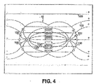
- FIG. 4 a dividing cell 10 is illustrated, at an earlier stage as compared to FIGS. 3A and 3B , under the influence of external TC fields (e.g., alternating fields in the frequency range of about 100 KHz to about 300 KHz), generally indicated as lines 100, with a corresponding spindle mechanism generally indicated at 120.
- the lines 120 are microtubules that are known to have a very strong dipole moment. This strong polarization makes the tubules, as well as other polar macromolecules and especially those that have a specific orientation within the cells or its surrounding, susceptible to electric fields.
- the present apparatus utilizes insulated electrodes
- the above-mentioned negative effects obtained when conductive electrodes are used i.e., ion concentration changes in the cells and the formation of harmful agents by electrolysis, do not occur when the present apparatus is used. This is because, in general, no actual transfer of charges takes place between the electrodes and the medium and there is no charge flow in the medium where the currents are capacitive, i.e., are expressed only as rotation of charges, etc.
- FIG. 5 is a simple schematic diagram of the electronic apparatus 200 illustrating the major components thereof.
- the electronic apparatus 200 generates the desired electric signals (TC signals) in the shape of waveforms or trains of pulses.
- the apparatus 200 includes a generator 210 and a pair of conductive leads 220 that are attached at one end thereof to the generator 210. The opposite ends of the leads 220 are connected to insulated conductors 230 that are activated by the electric signals (e.g., waveforms).
- the insulated conductors 230 are also referred to hereinafter as isolects 230.
- the apparatus 200 includes a temperature sensor 240 and a control box 250 which are both added to control the amplitude of the electric field generated so as not to generate excessive heating in the area that is treated.
- the generator 210 generates an alternating voltage waveform at frequencies in the range from about 50 KHz to about 500 KHz (preferably from about 100 KHz to about 300 KHz) (i.e., the TC fields).
- the required voltages are such that the electric field intensity in the tissue to be treated is in the range of about 0.1 V/cm to about 10 V/cm.
- the actual potential difference between the two conductors in the isolects 230 is determined by the relative impedances of the system components, as described below.
- control box 250 When the control box 250 is included, it controls the output of the generator 210 so that it will remain constant at the value preset by the user or the control box 250 sets the output at the maximal value that does not cause excessive heating, or the control box 250 issues a warning or the like when the temperature (sensed by temperature sensor 240) exceeds a preset limit.
- the leads 220 are standard isolated conductors with a flexible metal shield, preferably grounded so that it prevents the spread of the electric field generated by the leads 220.
- the isolects 230 have specific shapes and positioning so as to generate an electric field of the desired configuration, direction and intensity at the target volume and only there so as to focus the treatment.
- the specifications of the apparatus 200 as a whole and its individual components are largely influenced by the fact that at the frequency of the present TC fields (50 KHz-500 KHz), living systems behave according to their "Ohmic", rather than their dielectric properties.
- the only elements in the apparatus 200 that behave differently are the insulators of the isolects 230 (see FIGS. 7-9 ).
- the isolects 200 consist of a conductor in contact with a dielectric that is in contact with the conductive tissue thus forming a capacitor.
- the details of the construction of the isolects 230 is based on their electric behavior that can be understood from their simplified electric circuit when in contact with tissue as generally illustrated in FIG. 6 .
- the potential drop or the electric field distribution between the different components is determined by their relative electric impedance, i.e., the fraction of the field on each component is given by the value of its impedance divided by the total circuit impedance.
- the potential drop on element ⁇ V A A/(A+B+C+D+E).
- the impedance of the capacitance of the capacitors is dominant and determines the field distribution. Therefore, in order to increase the effective voltage drop across the tissues (field intensity), the impedance of the capacitors is to be decreased (i.e., increase their capacitance). This can be achieved by increasing the effective area of the "plates" of the capacitor, decrease the thickness of the dielectric or use a dielectric with high dielectric constant.
- the isolects 230 are configured differently depending upon the application in which the isolects 230 are to be used. There are two principle modes for applying the present electric fields (TC fields). First, the TC fields can be applied by external isolects and second, the TC fields can be applied by internal isolects.
- Electric fields (TC fields) that are applied by external isolects can be of a local type or widely distributed type.
- the first type includes, for example, the treatment of skin tumors and treatment of lesions close to the skin surface.
- FIG. 7 illustrates an exemplary embodiment where the isolects 230 are incorporated in a skin patch 300.
- the skin patch 300 can be a self-adhesive flexible patch with one or more pairs of isolects 230.
- the patch 300 includes internal insulation 310 (formed of a dielectric material) and the external insulation 260 and is applied to skin surface 301 that contains a tumor 303 either on the skin surface 301 or slightly below the skin surface 301.
- Tissue is generally indicated at 305.
- the internal insulation 310 must have a relatively high capacity. This can be achieved by a large surface area; however, this may not be desired as it will result in the spread of the field over a large area (e.g., an area larger than required to treat the tumor).
- the internal insulation 310 can be made very thin and/or the internal insulation 310 can be of a high dielectric constant. As the skin resistance between the electrodes (labeled as A and E in FIG. 6 ) is normally significantly higher than that of the tissue (labeled as C in FIG. 6 ) underneath it (1-10 K ⁇ vs. 0.1-1 K ⁇ ), most of the potential drop beyond the isolects occurs there.
- the characteristics of the internal insulation 310 should be such that they have impedance preferably under 100 K ⁇ at the frequencies of the present TC fields (e.g., 50 KHz to 500 KHz).
- the impedance preferably under 100 K ⁇ at the frequencies of the present TC fields (e.g., 50 KHz to 500 KHz).
- the impedance should be about 10 K Ohms or less, such that over 1% of the applied voltage falls on the tissues, for isolects with a surface area of 10 mm 2 , at frequencies of 200 KHz, the capacity should be on the order of 10 -10 F., which means that using standard insulations with a dielectric constant of 2-3, the thickness of the insulating layer 310 should be about 50-100 microns. An internal field 10 times stronger would be obtained with insulators with a dielectric constant of about 20-50.
- Using an insulating material with a high dielectric constant increases the capacitance of the electrodes, which results in a reduction of the electrodes' impedance to the AC signal that is applied by the generator 1 (shown in FIG. 5 ). Because the electrodes A, E are wired in series with the target tissue C, as shown in FIG. 6 , this reduction in impedance reduces the voltage drop in the electrodes, so that a larger portion of the applied AC voltage appears across the tissue C. Since a larger portion of the voltage appears across the tissue, the voltage that is being applied by the generator 1 can be advantageously lowered for a given field strength in the tissue.
- the desired field strength in the tissue being treated is preferably between about 0.1 V/cm and about 10 V/cm, and more preferably between about 2 V/cm and 3 V/cm or between about 1 V/cm and about 5 V/cm.
- the dielectric constant used in the electrode is sufficiently high, the impedance of the electrodes A, E drops down to the same order of magnitude as the series combination of the skin and tissue B, C, D.
- a suitable material with an extremely high dielectric constant is CaCu 3 Ti 4 O 12 , which has a dielectric constant of about 11,000 (measured at 100 kHz). When the dielectric constant is this high, useful fields can be obtained using a generator voltage that is on the order of a few tens of Volts.
- the insulation can be replaced by very high dielectric constant insulating materials, such as titanium dioxide (e.g., rutile), the dielectric constant can reach values of about 200.
- dielectric constant insulating materials such as titanium dioxide (e.g., rutile)
- the dielectric constant can reach values of about 200.
- lithium niobate LiNbO 3
- YIG yttrium iron garnet
- barium titanate BaTiO 3
- potassium tantalate KTaO 3
- KTaO 3 potassium tantalate
- LiTaO 3 lithium tantalate
- Insulator ceramics with high dielectric constants may also be used, such as a ceramic made of a combination of Lead Magnesium Niobate and Lead Titanate. It will be understood that the aforementioned exemplary materials can be used in combination with the present device where it is desired to use a material having a high dielectric constant.
- the isolects 230 can be shaped so as to conform with the body structure and/or (2) an intervening filler 270 (as illustrated in FIG. 10C ), such as a gel, that has high conductance and a high effective dielectric constant, can be added to the structure.
- the shaping can be pre-structured (see FIG.
- the gel can be contained in place by having an elevated rim as depicted in FIGS. 10C and 10C' .
- the gel can be made of hydrogels, gelatins, agar, etc., and can have salts dissolved in it to increase its conductivity.
- FIGS. 10A-10C' illustrate various exemplary configurations for the isolects 230.
- the exact thickness of the gel is not important so long as it is of sufficient thickness that the gel layer does not dry out during the treatment. In one exemplary embodiment, the thickness of the gel is about 0.5 mm to about 2 mm.
- the gel has high conductivity, is tacky, and is biocompatible for extended periods of time.
- One suitable gel is AG603 Hydrogel, which is available from AmGel Technologies, 1667 S. Mission Road, Fallbrook, CA 92028-4115, USA.
- the dielectric coating of each should be very thin, for example from between 1-50 microns. Since the coating is so thin, the isolects 230 can easily be damaged mechanically or undergo dielectric breakdown. This problem can be overcome by adding a protective feature to the isolect's structure so as to provide desired protection from such damage.
- the isolect 230 can be coated, for example, with a relatively loose net 340 that prevents access to the surface but has only a minor effect on the effective surface area of the isolect 230 (i.e., the capacity of the isolects 230 (cross section presented in FIG. 12B ). The loose net 340 does not effect the capacity and ensures good contact with the skin, etc.
- the loose net 340 can be formed of a number of different materials; however, in one exemplary embodiment, the net 340 is formed of nylon, polyester, cotton, etc.
- a very thin conductive coating 350 can be applied to the dielectric portion (insulating layer) of the isolect 230.
- One exemplary conductive coating is formed of a metal and more particularly of gold. The thickness of the coating 350 depends upon the particular application and also on the type of material used to form the coating 350; however, when gold is used, the coating has a thickness from about 0.1 micron to about 0.1 mm.
- the rim illustrated in FIG. 10 can also provide some mechanical protection.
- the dielectric strength of the internal insulation 310 determines at what field intensity the insulation will be "shorted" and cease to act as an intact insulation.
- insulators such as plastics, have dielectric strength values of about 100V per micron or more. As a high dielectric constant reduces the field within the internal insulator 310, a combination of a high dielectric constant and a high dielectric strength gives a significant advantage.
- FIGS. 8 and 9 illustrate a second type of treatment using the isolects 230, namely electric field generation by internal isolects 230.
- a body to which the isolects 230 are implanted is generally indicated at 311 and includes a skin surface 313 and a tumor 315.
- the isolects 230 can have the shape of plates, wires or other shapes that can be inserted subcutaneously or a deeper location within the body 311 so as to generate an appropriate field at the target area (tumor 315).
- the mode of isolects application is not restricted to the above descriptions.
- the distance between each member of the pair of isolects 230 can be large.
- the pairs can even by positioned opposite sides of a torso 410, as illustrated in FIG. 11 .
- the arrangement of the isolects 230 in FIG. 11 is particularly useful for treating a tumor 415 associated with lung cancer or gastro-intestinal tumors.
- the electric fields (TC fields) spread in a wide fraction of the body.
- the isolects insulating material should have minimal dielectric losses at the frequency ranges to be used during the treatment process. This factor can be taken into consideration when choosing the particular frequencies for the treatment.
- the direct heating of the tissues will most likely be dominated by the heating due to current flow (given by the I ⁇ R product).
- the isolect (insulated electrode) 230 and its surroundings should be made of materials that facilitate heat losses and its general structure should also facilitate head losses, i.e., minimal structures that block heat dissipation to the surroundings (air) as well as high heat conductivity.
- head losses i.e., minimal structures that block heat dissipation to the surroundings (air) as well as high heat conductivity.
- Using larger electrodes also minimizes the local sensation of heating, since it spreads the energy that is being transferred into the patient over a larger surface area.
- the heating is minimized to the point where the patient's skin temperature never exceeds about 39° C.
- Another way to reduce heating is to apply the field to the tissue being treated intermittently, by applying a field with a duty cycle between about 20% and about 50% instead of using a continuous field.
- a field with a duty cycle between about 20% and about 50% instead of using a continuous field.
- the field would be repetitively switched on for one second, then switched off for two seconds.
- the efficacy of treatment using a field with a 33% duty cycle is roughly the same as for a field with a duty cycle of 100%.
- the field could be switched on for one hour then switched off for one hour to achieve a duty cycle of 50%.
- switching at a rate of once per hour would not help minimize short-term heating.
- the effectiveness of the treatment can be enhanced by an arrangement of isolects 230 that focuses the field at the desired target while leaving other sensitive areas in low field density (i.e., protected areas).
- the proper placement of the isolects 230 over the body can be maintained using any number of different techniques, including using a suitable piece of clothing that keeps the isolects at the appropriate positions.
- FIG. 13 illustrates such an arrangement in which an area labeled as "P" represents a protected area. The lines of field force do not penetrate this protected area and the field there is much smaller than near the isolects 230 where target areas can be located and treated well. In contrast, the field intensity near the four poles is very high.
- the only areas that were visible discernable on the skin were the marks that represented the points of insertion of the isolects 230.
- the fact that the tumor was eliminated at the treated side was further demonstrated by cutting and inversing the skin so that its inside face was exposed. Such a procedure indicated that the tumor has been substantially, if not completely, eliminated on the treated side of the mouse.
- the success of the treatment was also further verified by histopathological examination.
- the present apparatus can further include a device for rotating the TC field relative to the living tissue.
- the alternating electric potential applies to the tissue being treated is rotated relative to the tissue using conventional devices, such as a mechanical device that upon activation, rotates various components of the present system.
- the TC fields are applied to different pairs of the insulated electrodes 230 in a consecutive manner.
- the generator 210 and the control system thereof can be arranged so that signals are sent at periodic intervals to select pairs of insulated electrodes 230, thereby causing the generation of the TC fields of different directions by these insulated electrodes 230. Because the signals are sent at select times from the generator to the insulated electrodes 230, the TC fields of changing directions are generated consecutively by different insulated electrodes 230.
- This arrangement has a number of advantages and is provided in view of the fact that the TC fields have maximal effect when they are parallel to the axis of cell division. Since the orientation of cell division is in most cases random, only a fraction of the dividing cells are affected by any given field. Thus, using fields of two or more orientations increases the effectiveness since it increases the chances that more dividing cells are affected by a given TC field.
- the inventor has recognized that applying the field in different directions sequentially will increase the overall killing power, because the field orientation that is most effectively in killing dividing cells will be applied to a larger population of the dividing cells.
- a number of examples for applying the field in different directions are discussed below.
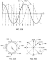
- FIGS. 27A, 27B, and 27C show a set of 6 electrodes E1-E6, and how the direction of the field through the target tissue 1510 can be changed by applying the AC signal from the generator 1 (shown in FIG. 1 ) across different pairs of electrodes. For example, if the AC signal is applied across electrodes E1 and E4, the field lines F would be vertical (as shown in FIG. 27A ), and if the signal is applied across electrodes E2 and E5, or across electrodes E3 and E6, the field lines F would be diagonal (as shown in FIGS. 27B and 27C , respectively). Additional field directions can be obtained by applying the AC signal across other pairs of electrodes. For example, a roughly horizontal field could be obtained by applying the signal across electrodes E2 and E6.
- the AC signal is applied between the various pairs of electrodes sequentially.
- An example of this arrangement is to apply the AC signal across electrodes E1 and E4 for one second, then apply the AC signal across electrodes E2 and E5 for one second, and then apply the AC signal across electrodes E3 and E6 for one second. This three-part sequence is then repeated for the desired period of treatment. Because the efficacy in cell-destruction is strongly dependant on the cell's orientation, cycling the field between the different directions increases the chance that the field will be oriented in a direction that favors cell destruction at least part of the time.
- FIGS. 27A-C is just one of many possible arrangement of multiple electrodes, and many other configurations of three or more electrodes could be used based on the same principles.
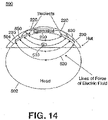
- FIG. 28 shows how the sequential application of signals across different sets of electrodes can be extended to three dimensions.
- a first array of electrodes A1-A9 is arranged around body part 1500, and a last array of electrodes N1-N9 is arranged around the body part 1500 a distance W away from the first array. Additional arrays of electrodes may optionally be added between the first array and the last array, but these additional arrays are not illustrated for clarity (so as not to obscure the electrodes A5-A9 and B5-B8 on the back of the body part 1500).
- the direction of the field through the target tissue can be changed by applying the AC signal from the generator 1 (shown in FIG. 1 ) across different pairs of electrodes.
- applying the AC signal between electrodes A2 and A7 would result in a field in a front-to-back direction between those two electrodes, and applying the AC signal between electrodes A5 and A9 would result in a roughly vertical field between those two electrodes.
- applying the AC signal across electrodes A2 and N7 would generate diagonal field lines in one direction through the body part 1500, and applying the AC signal across electrodes A2 and B7 would generate diagonal field lines in another direction through the body part.
- Using a three-dimensional array of electrodes also makes it possible to energize multiple pairs of electrodes simultaneously to induce fields in the desired directions. For example, if suitable switching is provided so that electrodes A2 through N2 are all connected to one terminal of the generator, and so that electrodes A7 through N7 are all connected to the other terminal of the generator, the resulting field would be a sheet that extends in a front-to-back direction for the entire width W. After the front-to-back field is maintained for a suitable duration (e.g., one second), the switching system (not shown) is reconfigured to connect electrodes A3 through N3 to one terminal of the generator, and electrodes A8 through N8 to the other terminal of the generator.
- a suitable duration e.g., one second
- the rotating sheet-shaped field may be added (sequentially in time) to the diagonal fields described above, to better target cells that are oriented along those diagonal axes.
- the signals may optionally be applied to combinations of electrodes simultaneously in order to form a desired resultant vector.
- a field that is rotated about the X axis by 20° with respect to the initial position can be obtained by switching electrodes A2 through N2 and A3 through N3 all to one terminal of the generator, and switching electrodes A7 through N7 and A8 through N8 all to the other terminal of the generator.
- Applying the signals to other combinations of electrodes will result in fields in other directions, as will be appreciated by persons skilled in the relevant arts. If appropriate computer control of the voltages is implemented, the field's direction can even be swept through space in a continuous (i.e., smooth) manner, as opposed to the stepwise manner described above.
- FIGS. 29A and 29B depict the results of in vitro experiments that show how the killing power of the applied field against dividing cells is a function of the field strength.
- B16F1 melanoma cells were subjected to a 100 kHz AC field at different field strengths, for a period of 24 hours at each strength.
- F-98 glioma cells were subjected to a 200 kHz AC field at different field strengths, for a period of 24 hours at each strength.
- the strength of the field (EF) is measured in Volts per cm.
- TER GR C ⁇ GR T GR C
- FIGS. 30A and 30B depict the results of in vitro experiments that show how the killing power of the applied field is a function of the frequency of the field.
- B16F1 melanoma cells FIG. 30A
- F-98 glioma cells FIG. 30B
- FIGS. 30A and 30B show the change in the growth rate, normalized to the field intensity (TER/EF). Data are shown as mean + SE.
- TER/EF field intensity
- a field with a frequency of about 120 kHz would be appropriate for destroying melanoma cells, and a field with a frequency on the order of 200 kHz would be appropriate for destroying glioma cells.
- the cells of any given type will have the exact same size. Instead, the cells will have a distribution of sizes, with some cells being smaller and some cells being larger. It is believed that the best frequency for damaging a particular cell is related to the physical characteristics (e.g., the size) of that particular cell. Thus, to best damage a population of cells with a distribution of sizes, it can be advantageous to apply a distribution of different frequencies to the population, where the selection of frequencies is optimized based on the expected size distribution of the target cells. For example, the data on FIG. 30B indicates that using two frequencies of 170 kHz and 250 kHz to destroy a population of glioma cells would be more effective than using a single frequency of 200 kHz.
- the various frequencies may be applied sequentially in time.
- field frequencies of 100, 150, 170, 200, 250, and 300 kHz may be applied during the first, second, third, fourth, fifth, and sixth minutes of treatment, respectively. That cycle of frequencies would then repeat during each successive six minutes of treatment.
- the frequency of the field is swept in a stepless manner , e.g. from 100 to 300 kHz. According to the invention, this frequency cycling is combined with the directional cycling described above.
- FIG. 31A is an example of such a combination using three directions (D1, D2, and D3) and three frequencies (F1, F2, and F3).
- FIG.31B illustrates a combination using three directions (D1, D2, and D3), together with sweeping the frequency , e.g. from 100 kHz to 300 kHz. Note that the break in the time axis between t1 and t2 provides the needed time for the sweeping frequency to rise to just under 300 kHz.
- the frequency sweeping (or stepping) may be synchronized with directional changes, as shown in FIG. 31A . Alternatively, the frequency sweeping (or stepping) may be asynchronous with respect to the directional changes, as shown in FIG. 31B .
- a signal that contains two or more frequencies components simultaneously is applied to the electrodes to treat a populations of cells that have a distribution of sizes.
- the various signals will add by superposition to create a field that includes all of the applied frequency components.
- the article of clothing 500 is in the form of a hat or cap or other type of clothing designed for placement on a head of a person.
- a head 502 is shown with the hat 500 being placed thereon and against a skin surface 504 of the head 502.
- An intra-cranial tumor or the like 510 is shown as being formed within the head 502 underneath the skin surface 504 thereof.
- the hat 500 is therefore intended for placement on the head 502 of a person who has a tumor 510 or the like.
- the insulated electrodes 230 in this embodiment are specifically contoured and arranged for a specific application.
- the treatment of intra-cranial tumors or other lesions or the like typically requires a treatment that is of a relatively long duration, e.g., days to weeks, and therefore, it is desirable to provide as much comfort as possible to the patient.
- the hat 500 is specifically designed to provide comfort during the lengthy treatment process while not jeopardizing the effectiveness of the treatment.
- the hat 500 includes a predetermined number of insulated electrodes 230 that are preferably positioned so as to produce the optimal TC fields at the location of the tumor 510.
- the lines of force of the TC field are generally indicated at 520.
- the tumor 510 is positioned within these lines of force 520.
- the insulated electrodes 230 are positioned within the hat 500 such that a portion or surface thereof is free to contact the skin surface 504 of the head 502.
- the insulated electrodes 230 are placed in contact with the skin surface 504 of the head 502 in positions that are selected so that the TC fields generated thereby are focused at the tumor 510 while leaving surrounding areas in low density.
- hair on the head 502 is shaved in selected areas to permit better contact between the insulated electrodes 230 and the skin surface 504; however, this is not critical.
- the hat 500 preferably includes a mechanism 530 that applies a force to the insulated electrodes 230 so that they are pressed against the skin surface 502.
- the mechanism 530 can be of a biasing type that applies a biasing force to the insulated electrodes 230 to cause the insulated electrodes 230 to be directed outwardly away from the hat 500.
- the mechanism 530 can slightly recoil to provide a comfortable fit between the insulated electrodes 230 and the head 502.
- the mechanism 530 is a spring based device that is disposed within the hat 500 and has one section that is coupled to and applies a force against the insulated electrodes 230.
- the insulated electrodes 230 are coupled to the generator 210 by means of conductors 220.
- the generator 210 can be either disposed within the hat 500 itself so as to provide a compact, self-sufficient, independent system or the generator 210 can be disposed external to the hat 500 with the conductors 220 exiting the hat 500 through openings or the like and then running to the generator 210.
- the generator 210 can be located in any number of different locations, some of which are in close proximity to the hat 500 itself, while others can be further away from the hat 500.
- the generator 210 can be disposed within a carrying bag or the like (e.g., a bag that extends around the patient's waist) which is worn by the patient or it can be strapped to an extremity or around the torso of the patient.
- the generator 210 can also be disposed in a protective case that is secured to or carried by another article of clothing that is worn by the patient.
- the protective case can be inserted into a pocket of a sweater, etc.
- FIG. 14 illustrates an embodiment where the generator 210 is incorporated directly into the hat 500.
- a number of insulated electrodes 230 along with the mechanism 530 are preferably formed as an independent unit, generally indicated at 540, that can be inserted into the hat 500 and electrically connected to the generator (not shown) via the conductors (not shown).
- the patient can easily insert and/or remove the units 540 from the hat 500 when they may need cleaning, servicing and/or replacement.
- the hat 500 is constructed to include select areas 550 that are formed in the hat 500 to receive and hold the units 540.
- each area 550 is in the form of an opening (pore) that is formed within the hat 500.
- the unit 540 has a body 542 and includes the mechanism 530 and one or more insulated electrodes 230.
- the mechanism 530 is arranged within the unit 540 so that a portion thereof (e.g., one end thereof) is in contact with a face of each insulated electrode 230 such that the mechanism 530 applies a biasing force against the face of the insulated electrode 230.
- the hat 500 can include pivotable clip members that pivot between an open position in which the opening 550 is free and a closed position in which the pivotable clip members engage portions (e.g., peripheral edges) of the insulated electrodes to retain and hold the insulated electrodes 230 in place. To remove the insulated electrodes 230, the pivotable clip members are moved to the open position. In the embodiment illustrated in FIG.
- the insulated electrodes 230 are retained within the openings 550 by an adhesive element 560 which in one embodiment is a two sided self-adhesive rim member that extends around the periphery of the insulated electrode 230.
- an adhesive element 560 which in one embodiment is a two sided self-adhesive rim member that extends around the periphery of the insulated electrode 230.
- a protective cover of one side of the adhesive rim 560 is removed and it is applied around the periphery of the exposed face of the insulated electrode 230, thereby securely attaching the adhesive rim 560 to the hat 500 and then the other side of the adhesive rim 560 is removed for application to the skin surface 504 in desired locations for positioning and securing the insulated electrode 230 to the head 502 with the tumor being positioned relative thereto for optimization of the TC fields.
- one side of the adhesive rim 560 is in contact with and secured to the skin surface 540, this is why it is desirable for the head 502 to be
- the adhesive rim 560 is designed to securely attach the unit 540 within the opening 550 in a manner that permits the unit 540 to be easily removed from the hat 500 when necessary and then replaced with another unit 540 or with the same unit 540.
- the unit 540 includes the biasing mechanism 530 for pressing the insulated electrode 230 against the skin surface 504 when the hat 500 is worn.
- the unit 540 can be constructed so that side opposite the insulated electrode 230 is a support surface formed of a rigid material, such as plastic, so that the biasing mechanism 530 (e.g., a spring) can be compressed therewith under the application of force and when the spring 530 is in a relaxed state, the spring 530 remains in contact with the support surface and the applies a biasing force at its other end against the insulated electrode 230.
- the biasing mechanism 530 e.g., spring
- the biasing mechanism 530 preferably has a contour corresponding to the skin surface 504 so that the insulated electrode 230 has a force applied thereto to permit the insulated electrode 230 to have a contour complementary to the skin surface 504, thereby permitting the two to seat flushly against one another.
- the mechanism 530 can be a spring, there are a number of other embodiments that can be used instead of a spring.
- the mechanism 530 can be in the form of an elastic material, such as a foam rubber, a foam plastic, or a layer containing air bubbles, etc.
- the unit 540 has an electric connector 570 that can be hooked up to a corresponding electric connector, such as a conductor 220, that is disposed within the hat 500.
- the conductor 220 connects at one end to the unit 540 and at the other end is connected to the generator 210.
- the generator 210 can be incorporated directly into the hat 500 or the generator 210 can be positioned separately (remotely) on the patient or on a bedside support, etc.
- a coupling agent such as a conductive gel
- a coupling agent is preferably used to ensure that an effective conductive environment is provided between the insulated electrode 230 and the skin surface 504.
- Suitable gel materials have been disclosed hereinbefore in the discussion of earlier embodiments.
- the coupling agent is disposed on the insulated electrode 230 and preferably, a uniform layer of the agent is provided along the surface of the electrode 230.
- One of the reasons that the units 540 need replacement at periodic times is that the coupling agent needs to be replaced and/or replenished. In other words, after a predetermined time period or after a number of uses, the patient removes the units 540 so that the coupling agent can be applied again to the electrode 230.
- FIGS. 17 and 18 illustrate another article of clothing which has the insulated electrodes 230 incorporated as part thereof.
- a bra or the like 700 is illustrated and includes a body that is formed of a traditional bra material, generally indicated at 705, to provide shape, support and comfort to the wearer.
- the bra 700 also includes a fabric support layer 710 on one side thereof.
- the support layer 710 is preferably formed of a suitable fabric material that is constructed to provide necessary and desired support to the bra 700.
- the bra 700 includes one or more insulated electrodes 230 disposed within the bra material 705.
- the one or more insulated electrodes are disposed along an inner surface of the bra 700 opposite the support 710 and are intended to be placed proximate to a tumor or the like that is located within one breast or in the immediately surrounding area.
- the insulated electrodes 230 in this embodiment are specifically constructed and configured for application to a breast or the immediate area.
- the insulated electrodes 230 used in this application do not have a planar surface construction but rather have an arcuate shape that is complementary to the general curvature found in a typical breast.
- a lining 720 is disposed across the insulated electrodes 230 so as to assist in retaining the insulated electrodes in their desired locations along the inner surface for placement against the breast itself.
- the lining 720 can be formed of any number of thin materials that are comfortable to wear against one's skin and in one exemplary embodiment, the lining 720 is formed of a fabric material.
- the bra 700 also preferably includes a biasing mechanism 800 as in some of the earlier embodiments.
- the biasing mechanism 800 is disposed within the bra material 705 and extends from the support 710 to the insulated electrode 230 and applies a biasing force to the insulated electrode 230 so that the electrode 230 is pressed against the breast. This ensures that the insulated electrode 230 remains in contact with the skin surface as opposed to lifting away from the skin surface, thereby creating a gap that results in a less effective treatment since the gap diminishes the efficiency of the TC fields.
- the biasing mechanism 800 can be in the form of a spring arrangement or it can be an elastic material that applies the desired biasing force to the insulated electrodes 230 so as to press the insulated electrodes 230 into the breast.
- the biasing mechanism 800 applies a force against the insulated electrodes 230 and when the patient places the bra 700 on their body, the insulated electrodes 230 are placed against the breast which itself applies a force that counters the biasing force, thereby resulting in the insulated electrodes 230 being pressed against the patient's breast.
- the biasing mechanism 800 is in the form of springs that are disposed within the bra material 705.
- a conductive gel 810 can be provided on the insulated electrode 230 between the electrode and the lining 720.
- the conductive gel layer 810 is formed of materials that have been previously described herein for performing the functions described above.
- An electric connector 820 is provided as part of the insulated electrode 230 and electrically connects to the conductor 220 at one end thereof, with the other end of the conductor 220 being electrically connected to the generator 210.
- the conductor 220 runs within the bra material 705 to a location where an opening is formed in the bra 700.
- the conductor 220 extends through this opening and is routed to the generator 210, which in this embodiment is disposed in a location remote from the bra 700.
- the generator 210 can be disposed within the bra 700 itself in another embodiment.
- the bra 700 can have a compartment formed therein which is configured to receive and hold the generator 210 in place as the patient wears the bra 700.
- the compartment can be covered with a releasable strap that can open and close to permit the generator 210 to be inserted therein or removed therefrom.
- the strap can be formed of the same material that is used to construct the bra 700 or it can be formed of some other type of material.
- the strap can be releasably attached to the surrounding bra body by fastening means, such as a hook and loop material, thereby permitting the patient to easily open the compartment by separating the hook and loop elements to gain access to the compartment for either inserting or removing the generator 210.
- the generator 210 also has a connector 211 for electrical connection to the conductor 220 and this permits the generator 210 to be electrically connected to the insulated electrodes 230.
- the insulated electrodes 230 are arranged in the bra 700 to focus the electric field (TC fields) on the desired target (e.g., a tumor).
- TC fields electric field
- the location of the insulated electrodes 230 within the bra 700 will vary depending upon the location of the tumor.
- the physician will then devise an arrangement of insulated electrodes 230 and the bra 700 is constructed in view of this arrangement so as to optimize the effects of the TC fields on the target area (tumor).
- the number and position of the insulated electrodes 230 will therefore depend upon the precise location of the tumor or other target area that is being treated.
- the exact size and shape of the insulated electrodes 230 can likewise vary. For example, if the insulated electrodes 230 are placed on the bottom section of the bra 700 as opposed to a more central location, the insulated electrodes 230 will have different shapes since the shape of the breast (as well as the bra) differs in these areas.
- FIG. 19 illustrates yet another embodiment in which the insulated electrodes 230 are in the form of internal electrodes that are incorporated into in the form of a probe or catheter 600 that is configured to enter the body through a natural pathway, such as the urethra, vagina, etc.
- the insulated electrodes 230 are disposed on an outer surface of the probe 600 and along a length thereof.
- the conductors 220 are electrically connected to the electrodes 230 and run within the body of the probe 600 to the generator 210 which can be disposed within the probe body or the generator 210 can be disposed independent of the probe 600 in a remote location, such as on the patient or at some other location close to the patient.
- the probe 600 can be configured to penetrate the skin surface or other tissues to reach an internal target that lies within the body.
- the probe 600 can penetrate the skin surface and then be positioned adjacent to or proximate to a tumor that is located within the body.
- the probe 600 is inserted through the natural pathway and then is positioned in a desired location so that the insulated electrodes 230 are disposed near the target area (i.e., the tumor).
- the generator 210 is then activated to cause the insulated electrodes 230 to generate the TC fields which are applied to the tumor for a predetermined length of time.
- the illustrated probe 600 is merely exemplary in nature and that the probe 600 can have other shapes and configurations so long as they can perform the intended function.
- the conductors (e.g., wires) leading from the insulated electrodes 230 to the generator 210 are twisted or shielded so as not to generate a field along the shaft.
- the probes can contain only one insulated electrode while the other can be positioned on the body surface.
- This external electrode should be larger or consist of numerous electrodes so as to result in low lines of force-current density so as not to affect the untreated areas.
- the placing of electrodes should be designed to minimize the field at potentially sensitive areas.
- the external electrodes may be held against the skin surface by a vacuum force (e.g., suction).
- FIG. 20 illustrates yet another embodiment in which a high standing collar member 900 (or necklace type structure) can be used to treat thyroid, parathyroid, laryngeal lesions, etc.
- FIG. 20 illustrates the collar member 900 in an unwrapped, substantially flat condition.
- the insulated electrodes 230 are incorporated into a body 910 of the collar member 900 and are configured for placement against a neck area of the wearer.
- the insulated electrodes 230 are coupled to the generator 210 according to any of the manner described hereinbefore and it will be appreciated that the generator 210 can be disposed within the body 910 or it can be disposed in a location external to the body 910.
- the collar body 910 can be formed of any number of materials that are traditionally used to form collars 900 that are disposed around a person's neck.
- the collar 900 preferably includes a means 920 for adjusting the collar 900 relative to the neck.
- complementary fasteners can be disposed on ends of the collar 900 to permit adjustment of the collar diameter.
- the construction of the present devices are particularly well suited for applications where the devices are incorporated into articles of clothing to permit the patient to easily wear a traditional article of clothing while at the same time the patient undergoes treatment.
- an extra level of comfort can be provided to the patient and the effectiveness of the treatment can be increased by incorporating some or all of the device components into the article of clothing.
- the precise article of clothing that the components are incorporated into will obviously vary depending upon the target area of the living tissue where tumor, lesion or the like exists.
- an article of clothing in the form of a sock-like structure or wrap can be provided and is configured to be worn around the testicle area of the patient in such a manner that the insulated electrodes thereof are positioned relative to the tumor such that the TC fields are directed at the target tissue.
- the precise nature or form of the article of clothing can vary greatly since the device components can be incorporated into most types of articles of clothing and therefore, can be used to treat any number of different areas of the patient's body where a condition may be present.
- FIGS. 21-22 in which another aspect of the present device is shown.
- a body 1000 such as any number of parts of a human or animal body, is illustrated.
- two or more insulated electrodes 230 are disposed in proximity to the body 1000 for treatment of a tumor or the like (not shown) using TC fields, as has been previously described in great detail in the above discussion of other embodiments.
- the insulated electrode 230 has a conductive component and has external insulation 260 that surrounds the conductive component thereof.
- Each insulated electrode 230 is preferably connected to a generator (not shown) by the lead 220.
- a conductive filler material e.g., conductive gel member 270
- the insulated electrodes 230 are spaced apart from one another and when the generator is actuated, the insulated electrodes 230 generate the TC fields that have been previously described in great detail.
- the lines of the electric field (TC field) are generally illustrated at 1010. As shown, the electric field lines 1010 extend between the insulated electrodes 230 and through the conductive gel member 270.
- the external insulation 260 of the insulated electrode 230 can begin to breakdown at any given location thereof.
- FIG. 22 illustrates that the external insulation 260 of one of the insulated electrodes 230 has experienced a breakdown 1020 at a face thereof which is adjacent the conductive gel member 270.
- the breakdown 1020 of the external insulation 260 results in the formation of a strong current flow-current density at this point (i.e., at the breakdown 1020).
- the increased current density is depicted by the increased number of electric field lines 1010 and the relative positioning and distance between adjacent electric field lines 1010.
- an overheated area 1030 is illustrated and is a region or area of the tissues/skin where an increased current density exits due to the breakdown 1020 in the external insulation 260.
- a patient can experience discomfort and pain in this area 1030 due to the strong current that exists in the area and the increased heat and possible burning sensation that exist in area 1030.
- FIG. 23 illustrates yet another embodiment in which a further application of the insulated electrodes 230 is shown.
- the conductive gel member 270 that is disposed between the insulated electrode 230 and the body 1000 includes a conductor 1100 that is floating in that the gel material forming the member 270 completely surrounds the conductor 1100.
- the conductor 1100 is a thin metal sheet plate that is disposed within the conductor 1100.
- a conductor such as the plate 1100
- the conductor 1100 practically has no effect on the field (except that the two opposing faces of the conductor 1100 are equipotential and the corresponding equipotentials are slightly shifted).
- the conductor 1100 is disposed parallel to the electric field, there is a significant distortion of the electric field.
- the area in the immediate proximity of the conductor 1100 is not equipotential, in contrast to the situation where there is no conductor 1100 present.
- the conductor 1100 When the conductor 1100 is disposed within the gel member 270, the conductor 1100 will typically not effect the electric field (TC field) for the reasons discussed above, namely that the conductor 1100 is normal to the lines of the electric field.
- the conductor 1100 will cause distortion of the electric field.
- the distortion can cause spreading of the lines of force (low field density-intensity) or concentration of the lines of field (higher density) of the electric field, according to the particular geometries of the insert and its surroundings, and thus, the conductor 1100 can exhibit, for example, a screening effect.
- the conductor 1100 completely encircles an organ 1101, the electric field in the organ itself will be zero since this type of arrangement is a Faraday cage.
- a conductive net or similar structure can be used to cover, completely or partially, the organ, thereby resulting in the electric field in the organ itself being zero or about zero.
- a net can be made of a number of conductive wires that are arranged relative to one another to form the net or a set of wires can be arranged to substantially encircle or otherwise cover the organ 1101.
- an organ 1103 to be treated (the target organ) is not covered with a member having a Faraday cage effect but rather is disposed in the electric field 1010 (TC fields).
- FIG. 24 illustrates an embodiment where the conductor 1100 is disposed within the body (i.e., under the skin) and it is located near a target (e.g., a target organ).
- a target e.g., a target organ.
- high field density of the TC fields
- another nearby organ can be protected by disposing the above described protective conductive net or the like around this nearby organ so as to protect this organ from the fields.
- a high field density condition can be provided near or at the target.
- the conductor 1100 permits the TC fields to be focused at a particular area (i.e., a target).
- the gel members 260 can each include a conductor as described with reference to FIG. 23 .
- the conductor in the gel member 260 protects the skin surface (tissues) from any side effects that may be realized if a breakdown in the insulation of the insulated electrode 230 occurs.
- the conductor 1100 creates a high field density near the target.
- a first insulated electrode 1200 and a second insulated electrode 1210 are provided and are disposed about a body 1300.
- Each insulated electrode includes a conductor that is preferably surrounded by an insulating material, thus the term "insulated electrode”.
- the conductive gel member 270 is provided between each of the first and second electrodes 1200, 1210 and the body 1300. Electric field lines are generally indicated at 1220 for this type of arrangement.
- the first insulated electrode 1200 has dimensions that are significantly greater than the dimensions of the second insulated electrode 1210 (the conductive gel member for the second insulated electrode 1210 will likewise be smaller).
- the pattern of the electric field lines 1220 is varied. More specifically, the electric field tapers inwardly toward the second insulated electrode 1210 due to the smaller dimensions of the second insulated electrode 1210.
- An area of high field density forms near the interface between the gel member 270 associated with the second insulated electrode 1210 and the skin surface. The various components of the system are manipulated so that the tumor within the skin or on the skin is within this high field density so that the area to be treated (the target) is exposed to electric field lines of a higher field density.
- FIG. 26 also illustrates a tapering TC field when a conductor 1400 (e.g., a conductive plate) is disposed in each of the conductive gel members 270.
- a conductor 1400 e.g., a conductive plate
- the size of the gel members 270 and the size of the conductors 1400 are the same or about the same despite the differences in the sizes of the insulated electrodes 1200, 1210.
- the conductors 1400 again can be characterized as "floating plates" since each conductor 1400 is surrounded by the material that forms the gel member 270. As shown in FIG.
- the decrease in the field density is generally indicated at 1410.
- a very inhomogeneous tapering field generally indicated at 1420, changing from very low density to very high density is formed between the one conductor 1400 and the insulated electrode 1210.
- One benefit of this exemplary configuration is that it permits the size of the insulated electrode to be reduced without causing an increase in the nearby field density.
- Electrodes that having very high dielectric constant insulation can be very expensive.
- Some insulated electrodes for example, can cost $500.00 or more; and further, the price is sensitive to the particular area of treatment. Thus, a reduction in the size of the insulated electrodes directly leads to a reduction in cost.
- microtubule spindles which contain highly polar elements (dimers), and the dividing cells themselves when they are in the cytokinesis stage (i.e. when they assume the shape of an hour-glass, with a narrow neck or "furrow” that connects the two daughter cells) become polarized in the presence of an applied electric field.
- polar entities When placed in a homogenous field, such polar entities will experience a rotating torque as equal forces of opposite direction act on the positive and negative charges.
- the force acting on any dipole in a field is a function of the angle between the dipole moment and the field. More specifically, the force is a function of the sine of the angle, with a maximum when the angle is 90° and zero force when the angle is zero.
- This torque tends to rotate the structures about their axis in a direction that would cause the dipole to orient along the lines of the field with the positive end of the structure facing the negative pole of the field.
- a homogenous field is applied to a structure that can rotate, eventually the structure will rotate to a position in which the field no longer exerts any torque on the structure.
- the direction of the field can be changed in discrete steps, as described above in connection with FIGS. 27 and 28 , to try to follow the rotation of the polar structures.
- the direction of the field can be changed in a continuous manner to try to follow the rotation of the polar structures.
- the rate of rotation of the field should be selected to match the rate of rotation of the dipole structures when those structures are subjected to the field. Under those circumstances, as the field undergoes 90° of rotation, the dipole will also undergo the same amount of rotation, and the force generating the rotation momentum remains maximal and constant.
- Two approaches may be used to obtain a rotating field that rotates in a continuous manner (as opposed to a step-wise manner).
- One approach which is usually not practical for in-vivo application, is to physically rotate the electrodes themselves.
- the other, more preferred, approach is to use 3 or more electrodes that surround the target region, and to simultaneously drive those electrodes with electric potentials in synchrony with one another, but with phase shifts between the driving signals.
- FIG. 32A illustrates a preferred embodiment that provides a full circular field rotation in one plane using two pairs of electrodes that do not share a common ground.
- a preferred placement for the electrodes is to place a first pair one pair of electrodes 1620 on opposite sides of the body 1610, and another pair of electrodes 1630 on opposite sides of the body 1610, offset by 90° from the first set of electrodes 1620.
- the electrodes are connected to a multi-output voltage source (not shown), with the multiple outputs synchronized to one another.
- one set of outputs of the voltage source is hooked up to the first pair of electrodes 1620 to generate a first AC potential difference between those two electrodes
- another set of outputs of the voltage source is hooked up to the second pair of electrodes 1630 to generate a second AC potential difference between those two electrodes.
- both sets of outputs are sinusoids with the same frequency and the first set of outputs is shifted in phase by 90° from the second set of outputs, the field will rotate in the target area 1612 within the body 1610.
- FIG. 32B is an example of a set of such waveforms, where the first AC waveform 1640 is applied across the first pair of electrodes 1620, and the second AC waveform 1650 is applied across the second pair of electrodes 1630.
- the second waveform 1650 is shifted by 90° with respect to the first waveform 1640.
- FIG. 32B only depicts the voltage waveforms 1640, 1650 at one electrode from the first pair of electrodes 1620 and at one electrode from the second pair of electrodes 1630.
- the voltage waveform at the other electrode in each of those pairs will be the inverse of the depicted voltage waveforms 1640, 1650.
- other electrode configurations may be used to obtain similar results when they are driven by appropriate outputs from the multi-output voltage source.
- three electrodes may be physically positioned around the target mass spaced 120° apart, and driven by three sinusoids that are phase-shifted by 120° with respect to each other (like the three-phase AC electrical power that is commonly used in the United States) to create a similar rotating field.
- FIG. 32C depicts the direction of the electric field vector at the target mass 1612 at various times when the waveforms 1640, 1650 (shown in FIG. 32B ) are applied to the electrodes 1620, 1630 (shown in FIG. 32A ).
- the tip of the vector 1660 traces a circle 1662 with time in the direction of the arrow 1664.
- the frequency of the rotation in this specific example is the same as the frequency of the field, so the time to make a complete rotation is the reciprocal of the field frequency.
- FIG. 33 depicts another set of waveforms that can be used to rotate the field, for the same electrode arrangement that is shown FIG. 32A .
- the voltage sources produce alternating waveforms 1670, 1680, the amplitude of each being modulated at some chosen frequency that is much lower than the frequency of the waveforms being modulated.
- the two modulating waveforms 1675, 1685 are provided with a phase shift between them.
- the vector sum of these two fields is a field that rotates with time and also has a "beat" or modulation of its amplitude with time.
- the modulation frequency is 10 times slower than the field alternation frequency and the phase shift is 90°.
- This arrangement can be used to rotate the field much more slowly than when the waveforms of FIG. 32B are used, and makes the rate of rotation independent of the underlying frequency of the waveform that is being modulated.
- the circular rotations described above in connection with FIGS. 32 and 33 can be modified, for example, to form ellipsoids by replacing sin( ⁇ +90°) with, for example, sin( ⁇ + ⁇ (t)).
- the number of electrodes and/or the positioning of the electrodes may be varies to achieve different rotations in either 2D or 3D space, based on the desired directional results and the accessibility of various body parts to the electrodes.
- the phase shifts between the various waves can be adjusted dynamically, being determined by some factor within the target area, as measured by a sensor (not shown) or some predetermined protocol.
- the protocol may, for example, be designed to sequentially target different polar macromolecules associated with a specific cell function. The switching from one frequency to the next may be determined by the products of some cellular reaction or function.
- FIG. 34A depicts the observed results when the field direction was changed every 10, 20, 50, 100, 200, 250, 500 and 1000 mSec back and forth between the two perpendicular directions, plus a control result where the field direction remained constant.
- the relative proliferation rates in FIG. 34A are expressed as ratios of cell proliferation compared to the proliferation when no field is applied. Thus, lower numbers denote more inhibition, and a proliferation rate of 1.0 is the rate of proliferation when no field is applied.
- the N values above each bar represent the number of experiments that were performed at each rate. The results indicate that the tested two-directional fields were more effective than continuous one-directional treatment, with the proliferation rate at 50-250 mSec field durations being 20-25% lower than for a constant direction field.
- In vivo experiments in which a Vx2 tumor was induced in rabbit kidneys show similar improvement in treatment efficacy using 50 and 250 mSec field durations as compared to a 1 Sec. field durations.
- FIG. 34B depicts the observed results when the field was rotated with rotation times of 5 ⁇ Sec, 9 mSec, 124 mSec, 250 mSec, 1 Sec, and 2 Sec, plus a control result where the field direction remained constant, with all the fields being applied for an overall time of 24 hours.
- the relative proliferation rates in FIG. 34B are expressed as ratios of cell proliferation compared to the proliferation when a one-orientation AC field (not shown) is applied. Thus, lower numbers denote more inhibition, and a proliferation rate of 1.0 is the rate of proliferation when the field orientation remains constant.
- FIG. 34C depicts the results of an experimental comparison between rotating and two-directional treatment, using a 250 mSec rotation rate and a 250 mSec field duration, respectively.
- the relative proliferation rates in this figure are expressed as ratios of cell proliferation compared to the proliferation when no field is applied. Thus, lower numbers denote more inhibition, and a proliferation rate of 1.0 is the rate of proliferation when no field is applied.
- the observed results indicate that using two-directional fields was significantly more effective than using a rotating field.
- FIG. 34D depicts the observed results for field frequencies of 140, 200, 300, and 500 kHz.
- the relative proliferation rates in this figure are expressed as ratios of cell proliferation compared to the proliferation when a one-orientation AC field (not shown) is applied. Thus, lower numbers denote more inhibition, and a proliferation rate of 1.0 is the rate of proliferation when the field orientation remains constant. Since the results show that cell proliferation was the smallest for a field frequency of 200 kHz (which has a field rotation rate of rates of 5 ⁇ Sec), a frequency of about 200 kHz is preferable for treating F-98 rat glioma.
- the rotating and multi-direction fields described herein may be used in vivo or in vitro, and the frequencies, field strengths, rates of rotation, and rates of direction switching may be varied depending on the application (e.g., for treating cancers other than rat glioma).
- tumor refers to a malignant tissue comprising transformed cells that grow uncontrollably.
- Tumors include leukemias, lymphomas, myelomas, plasmacytomas, and the like; and solid tumors.
- solid tumors include sarcomas and carcinomas such as, but not limited to: fibrosarcoma, myxosarcoma, liposarcoma, chondrosarcoma, osteogenic sarcoma, chordoma, angiosarcoma, endotheliosarcoma, lymphangiosarcoma, lymphangioendotheliosarcoma, synovioma, mesothelioma, Ewing's tumor, leiomyosarcoma, rhabdomyosarcoma, colon carcinoma, pancreatic cancer, breast cancer, ovarian cancer, prostate cancer, squamous cell carcinoma, basal cell carcinoma, adenocarcinom
- the invention is particularly advantageous for treating brain tumors, which are difficult to treat with surgery and radiation, and often inaccessible to chemotherapy or gene therapies.
- the present invention is suitable for use in treating skin and breast tumors ⁇ because of the ease of localized treatment provided by the present invention.
- the present invention can control uncontrolled growth associated with non-malignant or pre-malignant conditions, and other disorders involving inappropriate cell or tissue growth by application of an electric field in accordance with the invention to the tissue undergoing inappropriate growth.
- the invention is useful for the treatment of arteriovenous (AV) malformations, particularly in intracranial sites.
- AV arteriovenous
- the invention may also be used to treat psoriasis, a dermatologic condition that is characterized by inflammation and vascular proliferation; and benign prostatic hypertrophy, a condition associated with inflammation and possibly vascular proliferation. Treatment of other hyperproliferative disorders is also contemplated.
- undesirable fibroblast and endothelial cell proliferation associated with wound healing, leading to scar and keloid formation after surgery or injury, and restenosis after angioplasty or placement of coronary stents can be inhibited by application of an electric field in accordance with the present invention.
- the non-invasive nature of this invention makes it particularly desirable for these types of conditions, particularly to prevent development of internal scars and adhesions, or to inhibit restenosis of coronary, carotid, and other important arteries.
- the above-described embodiments may also be used prophylactically to prevent tumors from ever reaching a detectable size in the first place.
- the bra embodiment described above in connection with FIGS. 17 and 18 may be worn by a woman for an 8 hour session every day for a week, with the week-long course of treatment being repeated every few months to kill any cells that have become cancerous and started to proliferate.
- This mode of usage is particularly appropriate for people who are at high risk for a particular type of cancer (e.g., women with a strong history of breast cancer in their families, or people who have survived a bout of cancer and are at risk of a relapse).
- the course of prophylactic treatment may be tailored based on the type of cancer being targeted and/or to suit the convenience of the patient. For example, undergoing a four 16 hour sessions during the week of treatment may be more convenient for some patients than seven 8 hour session, and may be equally effective.
- the present invention provides an effective and simple means of selectively destroying dividing cells, e.g., tumor cells and parasitic organisms, while non-dividing cells or organisms are left unaffected by application of the invention on living tissue containing both types of cells or organisms.
- the present invention does not damage the normal cells or organisms.
- the present invention does not discriminate based upon cell type (e.g., cells having differing sizes) and therefore may be used to treat any number of types of sizes having a wide spectrum of characteristics, including varying dimensions.
Landscapes
- Health & Medical Sciences (AREA)
- Life Sciences & Earth Sciences (AREA)
- General Health & Medical Sciences (AREA)
- Engineering & Computer Science (AREA)
- Biomedical Technology (AREA)
- Nuclear Medicine, Radiotherapy & Molecular Imaging (AREA)
- Radiology & Medical Imaging (AREA)
- Animal Behavior & Ethology (AREA)
- Public Health (AREA)
- Veterinary Medicine (AREA)
- Orthopedic Medicine & Surgery (AREA)
- Cell Biology (AREA)
- Electrotherapy Devices (AREA)
- Micro-Organisms Or Cultivation Processes Thereof (AREA)
- Apparatus Associated With Microorganisms And Enzymes (AREA)
Applications Claiming Priority (3)
| Application Number | Priority Date | Filing Date | Title |
|---|---|---|---|
| US63987304P | 2004-12-27 | 2004-12-27 | |
| PCT/IB2005/004169 WO2006085150A2 (en) | 2004-12-27 | 2005-12-27 | Treating a tumor or the like with electric fields at different orientations |
| EP05856273A EP1833554A2 (en) | 2004-12-27 | 2005-12-27 | Treating a tumor or the like with electric fields at different orientations |
Related Parent Applications (1)
| Application Number | Title | Priority Date | Filing Date |
|---|---|---|---|
| EP05856273A Division EP1833554A2 (en) | 2004-12-27 | 2005-12-27 | Treating a tumor or the like with electric fields at different orientations |
Publications (2)
| Publication Number | Publication Date |
|---|---|
| EP3666328A1 EP3666328A1 (en) | 2020-06-17 |
| EP3666328B1 true EP3666328B1 (en) | 2022-04-06 |
Family
ID=36791623
Family Applications (2)
| Application Number | Title | Priority Date | Filing Date |
|---|---|---|---|
| EP05856273A Ceased EP1833554A2 (en) | 2004-12-27 | 2005-12-27 | Treating a tumor or the like with electric fields at different orientations |
| EP20152897.3A Active EP3666328B1 (en) | 2004-12-27 | 2005-12-27 | Treating a tumor or the like with electric fields at different orientations |
Family Applications Before (1)
| Application Number | Title | Priority Date | Filing Date |
|---|---|---|---|
| EP05856273A Ceased EP1833554A2 (en) | 2004-12-27 | 2005-12-27 | Treating a tumor or the like with electric fields at different orientations |
Country Status (6)
| Country | Link |
|---|---|
| US (1) | US7565206B2 (zh) |
| EP (2) | EP1833554A2 (zh) |
| JP (1) | JP5559460B2 (zh) |
| CN (2) | CN102488967B (zh) |
| CA (1) | CA2594231C (zh) |
| WO (1) | WO2006085150A2 (zh) |
Families Citing this family (136)
| Publication number | Priority date | Publication date | Assignee | Title |
|---|---|---|---|---|
| US7599746B2 (en) | 2000-02-17 | 2009-10-06 | Standen Ltd | Apparatus and method for preventing the spread of cancerous metastases and for elimination of metastases |
| US8447395B2 (en) * | 2000-02-17 | 2013-05-21 | Novocure Ltd | Treating bacteria with electric fields |
| US7136699B2 (en) * | 2002-10-02 | 2006-11-14 | Standen, Ltd. | Apparatus for destroying dividing cells |
| JP5280600B2 (ja) | 2000-02-17 | 2013-09-04 | パルティ、ヨーラム | 分裂中の細胞を破壊するための方法および装置 |
| US7089054B2 (en) * | 2002-10-02 | 2006-08-08 | Standen Ltd. | Apparatus and method for treating a tumor or the like |
| US8175698B2 (en) * | 2000-02-17 | 2012-05-08 | Novocure Ltd. | Treating bacteria with electric fields |
| US8131371B2 (en) * | 2002-04-08 | 2012-03-06 | Ardian, Inc. | Methods and apparatus for monopolar renal neuromodulation |
| US9636174B2 (en) | 2002-04-08 | 2017-05-02 | Medtronic Ardian Luxembourg S.A.R.L. | Methods for therapeutic renal neuromodulation |
| US20070129761A1 (en) | 2002-04-08 | 2007-06-07 | Ardian, Inc. | Methods for treating heart arrhythmia |
| US8774922B2 (en) | 2002-04-08 | 2014-07-08 | Medtronic Ardian Luxembourg S.A.R.L. | Catheter apparatuses having expandable balloons for renal neuromodulation and associated systems and methods |
| US9308043B2 (en) | 2002-04-08 | 2016-04-12 | Medtronic Ardian Luxembourg S.A.R.L. | Methods for monopolar renal neuromodulation |
| US7756583B2 (en) | 2002-04-08 | 2010-07-13 | Ardian, Inc. | Methods and apparatus for intravascularly-induced neuromodulation |
| US8145316B2 (en) | 2002-04-08 | 2012-03-27 | Ardian, Inc. | Methods and apparatus for renal neuromodulation |
| US7162303B2 (en) | 2002-04-08 | 2007-01-09 | Ardian, Inc. | Renal nerve stimulation method and apparatus for treatment of patients |
| US7620451B2 (en) | 2005-12-29 | 2009-11-17 | Ardian, Inc. | Methods and apparatus for pulsed electric field neuromodulation via an intra-to-extravascular approach |
| US7853333B2 (en) | 2002-04-08 | 2010-12-14 | Ardian, Inc. | Methods and apparatus for multi-vessel renal neuromodulation |
| US20070135875A1 (en) | 2002-04-08 | 2007-06-14 | Ardian, Inc. | Methods and apparatus for thermally-induced renal neuromodulation |
| US8150519B2 (en) | 2002-04-08 | 2012-04-03 | Ardian, Inc. | Methods and apparatus for bilateral renal neuromodulation |
| US8774913B2 (en) | 2002-04-08 | 2014-07-08 | Medtronic Ardian Luxembourg S.A.R.L. | Methods and apparatus for intravasculary-induced neuromodulation |
| US8145317B2 (en) | 2002-04-08 | 2012-03-27 | Ardian, Inc. | Methods for renal neuromodulation |
| US20080213331A1 (en) | 2002-04-08 | 2008-09-04 | Ardian, Inc. | Methods and devices for renal nerve blocking |
| US8347891B2 (en) | 2002-04-08 | 2013-01-08 | Medtronic Ardian Luxembourg S.A.R.L. | Methods and apparatus for performing a non-continuous circumferential treatment of a body lumen |
| US7653438B2 (en) | 2002-04-08 | 2010-01-26 | Ardian, Inc. | Methods and apparatus for renal neuromodulation |
| US20140018880A1 (en) | 2002-04-08 | 2014-01-16 | Medtronic Ardian Luxembourg S.A.R.L. | Methods for monopolar renal neuromodulation |
| US7617005B2 (en) | 2002-04-08 | 2009-11-10 | Ardian, Inc. | Methods and apparatus for thermally-induced renal neuromodulation |
| US6978174B2 (en) | 2002-04-08 | 2005-12-20 | Ardian, Inc. | Methods and devices for renal nerve blocking |
| US9308044B2 (en) | 2002-04-08 | 2016-04-12 | Medtronic Ardian Luxembourg S.A.R.L. | Methods for therapeutic renal neuromodulation |
| US8175711B2 (en) | 2002-04-08 | 2012-05-08 | Ardian, Inc. | Methods for treating a condition or disease associated with cardio-renal function |
| US20040082859A1 (en) | 2002-07-01 | 2004-04-29 | Alan Schaer | Method and apparatus employing ultrasound energy to treat body sphincters |
| DE10260149A1 (de) * | 2002-12-20 | 2004-07-01 | BSH Bosch und Siemens Hausgeräte GmbH | Vorrichtung zur Bestimmung des Leitwertes von Wäsche, Wäschetrockner und Verfahren zur Verhinderung von Schichtbildung auf Elektroden |
| PL376467A1 (en) * | 2003-01-27 | 2005-12-27 | Compumedics Limited | Online source reconstruction for eeg/meg and ecg/mcg |
| JP4750784B2 (ja) | 2004-04-23 | 2011-08-17 | ノヴォキュアー・リミテッド | 異なる周波数の電界による腫瘍等の治療 |
| PT2364748T (pt) * | 2004-12-07 | 2018-03-26 | Novocure Ltd | Eléctrodos para aplicar um campo eléctrico in-vivo ao longo de um extenso período de tempo |
| US20070021803A1 (en) | 2005-07-22 | 2007-01-25 | The Foundry Inc. | Systems and methods for neuromodulation for treatment of pain and other disorders associated with nerve conduction |
| EP3804809B1 (en) * | 2005-10-03 | 2023-12-27 | Novocure GmbH | Optimizing characteristics of an electric field to increase the field's effect on proliferating cells |
| US8019414B2 (en) | 2006-04-05 | 2011-09-13 | Novocure Ltd. | Treating cancer using electromagnetic fields in combination with other treatment regimens |
| EP2068739A4 (en) * | 2006-09-14 | 2013-01-23 | Lazure Technologies Llc | DEVICE AND METHOD FOR THE DESTRUCTION OF CANCER CELLS |
| PT2167194T (pt) * | 2007-03-06 | 2017-06-15 | Novocure Ltd | Tratamento do cancro utilizando campos electromagnéticos em combinação com terapia fotodinámica |
| PT2183024T (pt) * | 2007-08-14 | 2019-08-01 | Novocure Ltd | Tratando parasitas com campos elétricos |
| WO2009036459A1 (en) * | 2007-09-14 | 2009-03-19 | Lazure Technologies, Llc | Multi-tine probe and treatment by activation of opposing tines |
| WO2009036457A1 (en) * | 2007-09-14 | 2009-03-19 | Lazure Technologies, Llc | Multi-layer electrode ablation probe and related methods |
| WO2009036468A1 (en) * | 2007-09-14 | 2009-03-19 | Lazure Technologies, Llc | Transurethral systems and methods for ablation treatment of prostate tissue |
| DE102008013827A1 (de) * | 2008-03-12 | 2009-10-01 | Hans-Ulrich Dr. May | Behandlungsvorrichtung für Tiere |
| US20100100093A1 (en) * | 2008-09-16 | 2010-04-22 | Lazure Technologies, Llc. | System and method for controlled tissue heating for destruction of cancerous cells |
| US8652129B2 (en) | 2008-12-31 | 2014-02-18 | Medtronic Ardian Luxembourg S.A.R.L. | Apparatus, systems, and methods for achieving intravascular, thermally-induced renal neuromodulation |
| EP2376011B1 (en) | 2009-01-09 | 2019-07-03 | ReCor Medical, Inc. | Apparatus for treatment of mitral valve insufficiency |
| US8728139B2 (en) | 2009-04-16 | 2014-05-20 | Lazure Technologies, Llc | System and method for energy delivery to a tissue using an electrode array |
| US9526911B1 (en) | 2010-04-27 | 2016-12-27 | Lazure Scientific, Inc. | Immune mediated cancer cell destruction, systems and methods |
| CN103313671B (zh) | 2010-10-25 | 2017-06-06 | 美敦力Af卢森堡有限责任公司 | 用于神经调节治疗的估算及反馈的装置、系统及方法 |
| JP6078471B2 (ja) * | 2010-11-19 | 2017-02-08 | セント・ジュード・メディカル・エイトリアル・フィブリレーション・ディヴィジョン・インコーポレーテッド | 直流組織治療のための不関電極を有する電極カテーテル機器 |
| US9233257B1 (en) | 2010-11-22 | 2016-01-12 | Jacob Zabara | Electromagnetic radiation treatment |
| US8684901B1 (en) | 2010-11-22 | 2014-04-01 | Jacob Zabara | Electromagnetic radiation treatment for cancer and pathological genetic regulations |
| ES2967784T3 (es) | 2011-02-15 | 2024-05-03 | Hemosonics Llc | Caracterización de la hemostasia sanguínea y los parámetros de transporte de oxígeno |
| US8756792B2 (en) * | 2011-06-08 | 2014-06-24 | The Boeing Company | Digitally designed shims for joining parts of an assembly |
| WO2013134548A2 (en) | 2012-03-08 | 2013-09-12 | Medtronic Ardian Luxembourg S.A.R.L. | Ovarian neuromodulation and associated systems and methods |
| AU2013229776B2 (en) | 2012-03-08 | 2016-12-15 | Medtronic Af Luxembourg S.A.R.L. | Biomarker sampling in the context of neuromodulation devices and associated systems |
| US20140110296A1 (en) | 2012-10-19 | 2014-04-24 | Medtronic Ardian Luxembourg S.A.R.L. | Packaging for Catheter Treatment Devices and Associated Devices, Systems, and Methods |
| CN103908744A (zh) * | 2013-01-06 | 2014-07-09 | 张涛 | 一种低强度电流电场癌症治疗设备及方法 |
| US10779875B2 (en) | 2013-05-06 | 2020-09-22 | Novocure Gmbh | Optimizing treatment using TTfields by changing the frequency during the course of long term tumor treatment |
| US9655669B2 (en) | 2013-05-06 | 2017-05-23 | Novocure Limited | Optimizing treatment using TTFields by changing the frequency during the course of long term tumor treatment |
| US9980766B1 (en) | 2014-03-28 | 2018-05-29 | Medtronic Ardian Luxembourg S.A.R.L. | Methods and systems for renal neuromodulation |
| US10194980B1 (en) | 2014-03-28 | 2019-02-05 | Medtronic Ardian Luxembourg S.A.R.L. | Methods for catheter-based renal neuromodulation |
| US10194979B1 (en) | 2014-03-28 | 2019-02-05 | Medtronic Ardian Luxembourg S.A.R.L. | Methods for catheter-based renal neuromodulation |
| CN105476081A (zh) * | 2015-02-12 | 2016-04-13 | 北京至感传感器技术研究院有限公司 | 胸罩组件 |
| US9726647B2 (en) | 2015-03-17 | 2017-08-08 | Hemosonics, Llc | Determining mechanical properties via ultrasound-induced resonance |
| CN104984479B (zh) * | 2015-05-15 | 2017-10-17 | 陈初生 | 电子对撞对异性细胞的抑制系统及抑制方法 |
| US10188851B2 (en) | 2015-10-28 | 2019-01-29 | Novocure Limited | TTField treatment with optimization of electrode positions on the head based on MRI-based conductivity measurements |
| US10275565B2 (en) | 2015-11-06 | 2019-04-30 | The Boeing Company | Advanced automated process for the wing-to-body join of an aircraft with predictive surface scanning |
| US10521551B2 (en) | 2015-11-16 | 2019-12-31 | The Boeing Company | Methods for shimming flexible bodies |
| US10821283B2 (en) | 2016-04-04 | 2020-11-03 | Novocure Gmbh | Reducing motility of cancer cells using tumor treating fields (TTFields) |
| CA3029468A1 (en) | 2016-06-30 | 2018-01-04 | Zeev Bomzon | Arrays for longitudinal delivery of ttfields to a body |
| WO2018134733A1 (en) | 2017-01-19 | 2018-07-26 | Moshe Giladi | System for viewing cell cultures under a microscope whilst applying ttfields |
| CN106823145A (zh) * | 2017-03-24 | 2017-06-13 | 长沙普特斯科技有限公司 | 一种采用调幅电场治疗肿瘤的装置 |
| CN106823125A (zh) * | 2017-03-24 | 2017-06-13 | 长沙利星医药科技开发有限公司 | 一种采用调幅电场增强药物疗效的装置 |
| CN107362445A (zh) * | 2017-08-30 | 2017-11-21 | 东北师范大学 | 抗癌靶向药物指向静电场合成矢量增强装置 |
| CN109432601A (zh) * | 2017-10-20 | 2019-03-08 | 湖南安泰康成生物科技有限公司 | 用于破坏和抑制患者体内病变组织快速生长的设备 |
| CN107981860B (zh) * | 2017-12-08 | 2019-12-31 | 浙江大学 | 一种非接触非侵入无损伤的癫痫路径可达方式监测预警干预系统及获取干扰脑电分布的方法 |
| CN108158579B (zh) * | 2017-12-08 | 2020-01-21 | 浙江大学 | 一种非接触非侵入无损伤的癫痫自组织监测预警干预系统及获取干扰脑电分布的方法 |
| JP2021508533A (ja) | 2017-12-26 | 2021-03-11 | ギャラリー,インコーポレイテッド | 様々な用途のためのエネルギー送達の最適化 |
| EP3755416A1 (en) | 2018-02-20 | 2020-12-30 | University Of Iowa Research Foundation | Therapeutic systems using magnetic and electric fields |
| US11850440B2 (en) | 2019-08-22 | 2023-12-26 | University Of Iowa Research Foundation | Therapeutic systems using magnetic fields |
| US10953209B2 (en) | 2018-03-28 | 2021-03-23 | Board Of Regents Of The University Of Texas System | Treating tumors using TTFields combined with a PARP inhibitor |
| JP7139448B2 (ja) | 2018-04-09 | 2022-09-20 | ノボキュア ゲーエムベーハー | TTFields及びオーロラキナーゼ阻害剤による腫瘍の治療 |
| KR20200141478A (ko) | 2018-04-10 | 2020-12-18 | 지브 봄존 | 서로 다른 반복 시간을 가지는 두 개의 MRI 이미지들로부터 얻어진 1MHz 미만 저주파 교류 전도도 추산치 |
| CN116603165A (zh) | 2018-07-03 | 2023-08-18 | 斯坦福大学托管董事会 | 使用交变电场提高细胞膜通透性 |
| US11179322B2 (en) | 2018-07-10 | 2021-11-23 | Novocure Gmbh | Methods and compositions for treating tumors with TTFields and sorafenib |
| CA3103070C (en) | 2018-07-10 | 2024-01-09 | Novocure Gmbh | Inhibiting viral infection using alternating electric fields |
| JP7267393B2 (ja) | 2018-07-18 | 2023-05-01 | ノボキュア ゲーエムベーハー | 腫瘍治療場(tt場)の線量を定量化するための電力損失密度および関連する処置の使用 |
| DK3804648T3 (da) | 2018-08-23 | 2022-04-11 | Novocure Gmbh | Anvendelse af elektriske vekseltrømsfelter til forøgelse af permeabilitet af blodhjernebarrieren |
| US11160977B2 (en) | 2018-09-04 | 2021-11-02 | Novocure Gmbh | Delivering tumor treating fields (TTFields) to the infratentorial brain |
| JP2022501098A (ja) * | 2018-09-07 | 2022-01-06 | ノボキュア ゲーエムベーハー | T細胞の増殖を低減する交流電場を使用する自己免疫性疾患の治療 |
| US10712730B2 (en) | 2018-10-04 | 2020-07-14 | The Boeing Company | Methods of synchronizing manufacturing of a shimless assembly |
| EP3984590B1 (en) | 2018-10-15 | 2022-12-07 | Novocure GmbH | Generating tumor treating fields (ttfields) with high uniformity throughout the brain |
| EP3870271A1 (en) | 2018-10-25 | 2021-09-01 | Zeev Bomzon | Delivering alternating electric fields (e.g., ttfields) to a subject's spinal anatomy |
| MX2021002624A (es) | 2018-11-19 | 2021-05-12 | Novocure Gmbh | Arreglos para suministrar campos de tratamiento de tumores (ttfields) con subelementos direccionables selectivamente. |
| CA3110453C (en) | 2018-11-29 | 2024-02-27 | Novocure Gmbh | Enhanced-flexibility transducer arrays for delivering ttfields (tumor treating fields) |
| EP3961565A1 (en) | 2019-01-08 | 2022-03-02 | Novocure GmbH | Evaluating quality of segmentation of an image into different types of tissue for planning treatment using tumor treating fields (ttfields) |
| CN113573774A (zh) | 2019-02-26 | 2021-10-29 | 诺沃库勒有限责任公司 | 基于靶向癌细胞的电特性确定TTfield治疗的频率 |
| CN113453638A (zh) | 2019-02-27 | 2021-09-28 | 诺沃库勒有限责任公司 | 使用可植入换能器阵列递送肿瘤治疗场(TTFields) |
| CN109717841B (zh) * | 2019-03-12 | 2022-02-22 | 西南医科大学 | 一种皮肤病变内源性电场测量装置及方法 |
| JP7419391B2 (ja) | 2019-03-29 | 2024-01-22 | ノボキュア ゲーエムベーハー | PTGER3阻害剤によりTTFields-耐性がん細胞におけるTTFieldsに対する感受性を回復させるための方法 |
| PL3960232T3 (pl) | 2019-04-17 | 2023-05-15 | Novocure Gmbh | Załadowanie danych z układu izolowanego bez naruszania izolacji |
| WO2021019403A1 (en) | 2019-07-31 | 2021-02-04 | Yoram Wasserman | Applying tumor treating fields (ttfields) via electrodes embedded into skull implants |
| JP2022545794A (ja) | 2019-08-30 | 2022-10-31 | ノボキュア ゲーエムベーハー | 頸部への腫瘍治療電界(TTFields)の印加 |
| CN112652213B (zh) * | 2019-10-12 | 2022-09-02 | 王宪 | 一种细胞有丝分裂动态模拟教具 |
| US20210169568A1 (en) * | 2019-12-09 | 2021-06-10 | Biosense Webster (Israel) Ltd. | Oriented irreversible-electroporation (ire) pulses to compensate for cell size and orientation |
| KR20220122679A (ko) | 2019-12-31 | 2022-09-02 | 노보큐어 게엠베하 | 채널들의 스위칭 및 진폭 조정 중 스파이크들을 방지하는 고전압, 고효율 사인파 생성기 |
| WO2021136960A1 (en) * | 2019-12-31 | 2021-07-08 | Novocure Gmbh | Methods, systems, and apparatuses for combined tumor treating fields and mental health therapy |
| CN114901344A (zh) | 2019-12-31 | 2022-08-12 | 诺沃库勒有限责任公司 | 具有可单独访问的电极元件和温度传感器的用于传递肿瘤治疗场(tt场)的阵列 |
| EP4168108A1 (en) | 2020-06-19 | 2023-04-26 | The Methodist Hospital dba Houston Methodist Hospital | Method and apparatus for oncomagnetic treatment |
| US11818943B2 (en) | 2020-06-25 | 2023-11-14 | Novocure Gmbh | Fabricating organic light emitting diodes (OLEDs) using tubulin |
| TWI830958B (zh) * | 2020-10-16 | 2024-02-01 | 瑞士商諾沃庫勒有限責任公司 | 用於判定傳感器陣列在個體之身體上之最佳位置以及規劃電極元件集合在個體之身體上之定位的方法 |
| KR102556846B1 (ko) * | 2020-10-26 | 2023-07-18 | 주식회사 뉴아인 | 비정상 분열 세포에 대한 사멸 유도 장치 및 이의 구동 방법 |
| CN112690757B (zh) * | 2020-12-17 | 2022-06-14 | 成都柔电云科科技有限公司 | 压力性损伤监测及反馈设备、反馈调节系统 |
| CN112834573A (zh) * | 2020-12-30 | 2021-05-25 | 武汉大学 | 一种中频微电场生物效应快速试验方法 |
| CN113005037A (zh) * | 2021-04-12 | 2021-06-22 | 深圳市第二人民医院(深圳市转化医学研究院) | 一种用于细胞培养的电极绝缘垫及其非接触电场装置和方法 |
| CN113122448A (zh) * | 2021-04-12 | 2021-07-16 | 深圳市第二人民医院(深圳市转化医学研究院) | 一种用于细胞培养的非接触电场装置及其细胞培养方法 |
| CN113476746A (zh) * | 2021-07-20 | 2021-10-08 | 杭州维纳安可医疗科技有限责任公司 | 抑制病变细胞分裂的设备、控制方法及控制装置 |
| CN113616922A (zh) * | 2021-07-20 | 2021-11-09 | 杭州维纳安可医疗科技有限责任公司 | 目标电场的发生装置及控制方法 |
| CN113546322A (zh) * | 2021-07-26 | 2021-10-26 | 昆仑智鼎(北京)医疗技术有限公司 | 治疗用三维磁环装置及其应用 |
| CN113577562A (zh) * | 2021-07-26 | 2021-11-02 | 昆仑智鼎(北京)医疗技术有限公司 | 用于选择性破坏或抑制肿瘤细胞有丝分裂的交变电场装置 |
| CN113546316A (zh) * | 2021-07-26 | 2021-10-26 | 昆仑智鼎(北京)医疗技术有限公司 | 三维磁环的交变电场装置 |
| CN113521542A (zh) * | 2021-07-26 | 2021-10-22 | 昆仑智鼎(北京)医疗技术有限公司 | 一种治疗用磁环阵列装置 |
| CN113521541A (zh) * | 2021-07-26 | 2021-10-22 | 昆仑智鼎(北京)医疗技术有限公司 | 用于选择性破坏或抑制肿瘤细胞有丝分裂的装置 |
| CN113521543A (zh) * | 2021-07-26 | 2021-10-22 | 昆仑智鼎(北京)医疗技术有限公司 | 磁环阵列治疗装置 |
| CN113546323A (zh) * | 2021-07-26 | 2021-10-26 | 昆仑智鼎(北京)医疗技术有限公司 | 治疗用磁环阵列装置 |
| CN113667599A (zh) * | 2021-08-19 | 2021-11-19 | 杭州维纳安可医疗科技有限责任公司 | 抑制细菌增殖的系统及其控制方法 |
| CN114099961A (zh) * | 2021-12-22 | 2022-03-01 | 江苏海莱新创医疗科技有限公司 | 电极贴片的贴敷方法 |
| CN114534091B (zh) * | 2022-02-17 | 2022-09-09 | 湖南安泰康成生物科技有限公司 | 利用电场抑制肿瘤增殖的设备及其控制装置 |
| WO2024003791A1 (en) * | 2022-06-30 | 2024-01-04 | Novocure Gmbh | Electrode assembly for applying tumor treating fields (ttfields) that includes a plurality of thermally linked but electrically isolated graphite sheets |
| WO2024069504A1 (en) * | 2022-09-30 | 2024-04-04 | Novocure Gmbh | Reducing electrosensation while treating a subject using alternating electric fields by controlling ramp-up characteristics |
| WO2024069523A1 (en) | 2022-09-30 | 2024-04-04 | Novocure Gmbh | Changing the orientation of tumor treating fields (ttfields) by adjusting the amplitudes of two or more electric fields that are all in-phase with each other |
| WO2024090939A1 (ko) * | 2022-10-25 | 2024-05-02 | 주식회사 필드큐어 | 전기장 전달 시스템 및 방법 |
| CN115779273A (zh) * | 2022-11-03 | 2023-03-14 | 赛福凯尔(绍兴)医疗科技有限公司 | 电场能量聚焦的发射装置及方法 |
| CN116269733B (zh) * | 2023-03-20 | 2024-05-03 | 成都飞云科技有限公司 | 一种脉冲消融导管、装置及脉冲消融方法 |
| CN116196554B (zh) * | 2023-03-23 | 2024-03-12 | 湖南安泰康成生物科技有限公司 | 一种使用多个电场覆盖肿瘤细胞敏感频率以治疗肿瘤的系统 |
Family Cites Families (62)
| Publication number | Priority date | Publication date | Assignee | Title |
|---|---|---|---|---|
| FR446660A (fr) | 1911-09-02 | 1912-12-12 | Gottlieb Schuettel | Dispositif pour métiers continus à anneaux pour monter les curseurs sur les anneaux |
| US3991770A (en) | 1974-01-24 | 1976-11-16 | Leveen Harry H | Method for treating benign and malignant tumors utilizing radio frequency, electromagnetic radiation |
| JPS5134585A (ja) * | 1974-09-18 | 1976-03-24 | Katsuzo Ishige | Koshuhairyoki |
| US4016886A (en) | 1974-11-26 | 1977-04-12 | The United States Of America As Represented By The United States Energy Research And Development Administration | Method for localizing heating in tumor tissue |
| US4121592A (en) | 1975-08-04 | 1978-10-24 | Critical Systems, Inc. | Apparatus for heating tissue |
| DE2813068A1 (de) | 1978-03-25 | 1979-10-04 | Philips Patentverwaltung | Verfahren und vorrichtung zur ermittlung von inneren koerperstrukturen |
| US4346715A (en) * | 1978-07-12 | 1982-08-31 | The United States Of America As Represented By The Administrator Of The National Aeronautics And Space Administration | Hyperthermia heating apparatus |
| US4472506A (en) | 1981-01-13 | 1984-09-18 | Liburdy Robert P | Method for determining cell membrane dielectric breakdown |
| US4467809A (en) | 1982-09-17 | 1984-08-28 | Biolectron, Inc. | Method for non-invasive electrical stimulation of epiphyseal plate growth |
| US4622952A (en) | 1983-01-13 | 1986-11-18 | Gordon Robert T | Cancer treatment method |
| CA1244889A (en) | 1983-01-24 | 1988-11-15 | Kureha Chemical Ind Co Ltd | HYPERTHERMIA DEVICE |
| DE3323415C2 (de) * | 1983-06-29 | 1985-04-25 | Kernforschungsanlage Jülich GmbH, 5170 Jülich | Verwendung eines Verfahrens und einer Vorrichtung zur Bestimmung von Zellinhaltstoffe sezernierenden Zellen |
| SE455920B (sv) | 1986-01-29 | 1988-08-22 | Hans Wiksell | Anordning for hypertermibehandling av tumorer |
| US4923814A (en) | 1986-05-09 | 1990-05-08 | Electropore, Inc. | High speed, high power apparatus for vesicle prealignment, poration, loading and fusion in uniform electric fields and method therefor |
| CN86103803B (zh) | 1986-06-05 | 1987-11-18 | 北京信息工程学院 | 静电场治疗装置 |
| US4822470A (en) | 1987-10-09 | 1989-04-18 | Baylor College Of Medicine | Method of and apparatus for cell poration and cell fusion using radiofrequency electrical pulses |
| US4936303A (en) | 1987-11-20 | 1990-06-26 | Ultrathermics | Ultrasonic heating apparatus and method |
| JPH0629196B2 (ja) | 1987-12-01 | 1994-04-20 | 甲子郎 梅村 | 超音波による腫瘍治療用生理作用増強剤 |
| US5389069A (en) | 1988-01-21 | 1995-02-14 | Massachusetts Institute Of Technology | Method and apparatus for in vivo electroporation of remote cells and tissue |
| FR2627987B3 (fr) | 1988-03-04 | 1990-02-02 | Indiba Sa | Appareil electronique pour la therapie medicale et cosmetique |
| US5158071A (en) | 1988-07-01 | 1992-10-27 | Hitachi, Ltd. | Ultrasonic apparatus for therapeutical use |
| JPH0265876A (ja) * | 1988-08-31 | 1990-03-06 | Shimadzu Corp | キャビティ型ハイパーサーミア装置 |
| GB8904998D0 (en) | 1989-03-04 | 1989-04-19 | Matthews Tony | Anaesthetising apparatus |
| US5099756A (en) | 1989-06-01 | 1992-03-31 | Harry H. Leveen | Radio frequency thermotherapy |
| JP2643457B2 (ja) * | 1989-06-28 | 1997-08-20 | 三菱電機株式会社 | プラズマ処理装置及びその方法 |
| US5441746A (en) | 1989-12-22 | 1995-08-15 | Molecular Bioquest, Inc. | Electromagnetic wave absorbing, surface modified magnetic particles for use in medical applications, and their method of production |
| US5236410A (en) | 1990-08-02 | 1993-08-17 | Ferrotherm International, Inc. | Tumor treatment method |
| WO1992019286A1 (en) | 1991-05-03 | 1992-11-12 | University Technologies International, Inc. | Biofilm reduction method |
| US5441532A (en) | 1991-06-26 | 1995-08-15 | Massachusetts Institute Of Technology | Adaptive focusing and nulling hyperthermia annular and monopole phased array applicators |
| US5683366A (en) * | 1992-01-07 | 1997-11-04 | Arthrocare Corporation | System and method for electrosurgical tissue canalization |
| US5468223A (en) | 1992-11-30 | 1995-11-21 | C.N.R.S. Paris | Electrochemotherapy |
| US5386837A (en) | 1993-02-01 | 1995-02-07 | Mmtc, Inc. | Method for enhancing delivery of chemotherapy employing high-frequency force fields |
| JPH06242269A (ja) * | 1993-02-19 | 1994-09-02 | Yokogawa Electric Corp | 超音波メータ |
| FR2703253B1 (fr) | 1993-03-30 | 1995-06-23 | Centre Nat Rech Scient | Applicateur d'impulsions electriques pour traitement de tissus biologiques. |
| US5501703A (en) * | 1994-01-24 | 1996-03-26 | Medtronic, Inc. | Multichannel apparatus for epidural spinal cord stimulator |
| IL108775A (en) | 1994-02-25 | 2003-09-17 | Univ Ramot | Method for efficient incorporation of molecules into cells |
| US5704355A (en) | 1994-07-01 | 1998-01-06 | Bridges; Jack E. | Non-invasive system for breast cancer detection |
| US6447499B2 (en) | 1995-07-28 | 2002-09-10 | James R. Gray | Use of a polarized field to modify the efficacy of a bioactive agent |
| US5606971A (en) | 1995-11-13 | 1997-03-04 | Artann Corporation, A Nj Corp. | Method and device for shear wave elasticity imaging |
| US5718246A (en) | 1996-01-03 | 1998-02-17 | Preferential, Inc. | Preferential induction of electrically mediated cell death from applied pulses |
| US5984882A (en) | 1996-08-19 | 1999-11-16 | Angiosonics Inc. | Methods for prevention and treatment of cancer and other proliferative diseases with ultrasonic energy |
| US5869326A (en) | 1996-09-09 | 1999-02-09 | Genetronics, Inc. | Electroporation employing user-configured pulsing scheme |
| US6241701B1 (en) * | 1997-08-01 | 2001-06-05 | Genetronics, Inc. | Apparatus for electroporation mediated delivery of drugs and genes |
| US6055453A (en) | 1997-08-01 | 2000-04-25 | Genetronics, Inc. | Apparatus for addressing needle array electrodes for electroporation therapy |
| WO1999011771A1 (en) | 1997-09-04 | 1999-03-11 | Science Research Laboratory, Inc. | Cell separation using electric fields |
| US6027488A (en) | 1998-06-03 | 2000-02-22 | Genetronics, Inc. | Flow-through electroporation system for ex vivo gene therapy |
| US5976092A (en) | 1998-06-15 | 1999-11-02 | Chinn; Douglas O. | Combination stereotactic surgical guide and ultrasonic probe |
| US6319901B1 (en) | 1998-10-15 | 2001-11-20 | Ichor Medical Systems, Inc. | Methods for prolonging cell membrane permeability |
| JP4102031B2 (ja) | 1999-03-09 | 2008-06-18 | サーメイジ インコーポレイテッド | 組織を治療するのための装置および方法 |
| US6678558B1 (en) | 1999-03-25 | 2004-01-13 | Genetronics, Inc. | Method and apparatus for reducing electroporation-mediated muscle reaction and pain response |
| US6366808B1 (en) | 2000-03-13 | 2002-04-02 | Edward A. Schroeppel | Implantable device and method for the electrical treatment of cancer |
| US6853864B2 (en) | 2000-02-02 | 2005-02-08 | Catholic University Of America, The | Use of electromagnetic fields in cancer and other therapies |
| JP5280600B2 (ja) * | 2000-02-17 | 2013-09-04 | パルティ、ヨーラム | 分裂中の細胞を破壊するための方法および装置 |
| US7016725B2 (en) * | 2001-11-06 | 2006-03-21 | Standen Ltd. | Method and apparatus for destroying dividing cells |
| US7146210B2 (en) * | 2000-02-17 | 2006-12-05 | Standen Ltd. | Apparatus and method for optimizing tumor treatment efficiency by electric fields |
| US6868289B2 (en) * | 2002-10-02 | 2005-03-15 | Standen Ltd. | Apparatus for treating a tumor or the like and articles incorporating the apparatus for treatment of the tumor |
| US6546290B1 (en) | 2000-04-12 | 2003-04-08 | Roamitron Holding S.A. | Method and apparatus for electromedical therapy |
| KR20020074599A (ko) * | 2001-03-20 | 2002-10-04 | 서동학 | 열변색 고분자 수화겔(thermochromic polymer hydrogel)조성물 및 그의 제조방법 |
| US7083580B2 (en) * | 2001-04-06 | 2006-08-01 | Mattioli Engineering Ltd. | Method and apparatus for skin absorption enhancement and transdermal drug delivery |
| US6994706B2 (en) | 2001-08-13 | 2006-02-07 | Minnesota Medical Physics, Llc | Apparatus and method for treatment of benign prostatic hyperplasia |
| JP4750784B2 (ja) | 2004-04-23 | 2011-08-17 | ノヴォキュアー・リミテッド | 異なる周波数の電界による腫瘍等の治療 |
| PT2364748T (pt) | 2004-12-07 | 2018-03-26 | Novocure Ltd | Eléctrodos para aplicar um campo eléctrico in-vivo ao longo de um extenso período de tempo |
-
2005
- 2005-12-27 EP EP05856273A patent/EP1833554A2/en not_active Ceased
- 2005-12-27 CN CN201110226148.3A patent/CN102488967B/zh active Active
- 2005-12-27 CN CN200580048335XA patent/CN101124011B/zh active Active
- 2005-12-27 EP EP20152897.3A patent/EP3666328B1/en active Active
- 2005-12-27 CA CA2594231A patent/CA2594231C/en active Active
- 2005-12-27 WO PCT/IB2005/004169 patent/WO2006085150A2/en active Application Filing
- 2005-12-27 JP JP2007547714A patent/JP5559460B2/ja active Active
- 2005-12-27 US US11/318,702 patent/US7565206B2/en not_active Expired - Lifetime
Also Published As
| Publication number | Publication date |
|---|---|
| WO2006085150A2 (en) | 2006-08-17 |
| CN102488967A (zh) | 2012-06-13 |
| WO2006085150A3 (en) | 2006-10-19 |
| EP1833554A2 (en) | 2007-09-19 |
| JP2008525080A (ja) | 2008-07-17 |
| JP5559460B2 (ja) | 2014-07-23 |
| CN101124011B (zh) | 2011-08-31 |
| EP3666328A1 (en) | 2020-06-17 |
| CN102488967B (zh) | 2016-03-30 |
| CA2594231C (en) | 2016-04-19 |
| CN101124011A (zh) | 2008-02-13 |
| US7565206B2 (en) | 2009-07-21 |
| US20060167499A1 (en) | 2006-07-27 |
| CA2594231A1 (en) | 2006-08-17 |
Similar Documents
| Publication | Publication Date | Title |
|---|---|---|
| EP3666328B1 (en) | Treating a tumor or the like with electric fields at different orientations | |
| US8706261B2 (en) | Treating a tumor or the like with electric fields at different frequencies | |
| US7890183B2 (en) | Treating parasites with electric fields | |
| CA2697012C (en) | Treating bacteria with electric fields | |
| US7912540B2 (en) | Article of clothing for treating a tumor or the like | |
| US6868289B2 (en) | Apparatus for treating a tumor or the like and articles incorporating the apparatus for treatment of the tumor |
Legal Events
| Date | Code | Title | Description |
|---|---|---|---|
| PUAI | Public reference made under article 153(3) epc to a published international application that has entered the european phase |
Free format text: ORIGINAL CODE: 0009012 |
|
| STAA | Information on the status of an ep patent application or granted ep patent |
Free format text: STATUS: THE APPLICATION HAS BEEN PUBLISHED |
|
| AC | Divisional application: reference to earlier application |
Ref document number: 1833554 Country of ref document: EP Kind code of ref document: P |
|
| AK | Designated contracting states |
Kind code of ref document: A1 Designated state(s): AT BE BG CH CY CZ DE DK EE ES FI FR GB GR HU IE IS IT LI LT LU LV MC NL PL PT RO SE SI SK TR |
|
| RAP1 | Party data changed (applicant data changed or rights of an application transferred) |
Owner name: NOVOCURE GMBH |
|
| STAA | Information on the status of an ep patent application or granted ep patent |
Free format text: STATUS: REQUEST FOR EXAMINATION WAS MADE |
|
| 17P | Request for examination filed |
Effective date: 20200807 |
|
| RBV | Designated contracting states (corrected) |
Designated state(s): AT BE BG CH CY CZ DE DK EE ES FI FR GB GR HU IE IS IT LI LT LU LV MC NL PL PT RO SE SI SK TR |
|
| REG | Reference to a national code |
Ref country code: HK Ref legal event code: DE Ref document number: 40028857 Country of ref document: HK |
|
| STAA | Information on the status of an ep patent application or granted ep patent |
Free format text: STATUS: EXAMINATION IS IN PROGRESS |
|
| 17Q | First examination report despatched |
Effective date: 20210817 |
|
| GRAP | Despatch of communication of intention to grant a patent |
Free format text: ORIGINAL CODE: EPIDOSNIGR1 |
|
| STAA | Information on the status of an ep patent application or granted ep patent |
Free format text: STATUS: GRANT OF PATENT IS INTENDED |
|
| GRAS | Grant fee paid |
Free format text: ORIGINAL CODE: EPIDOSNIGR3 |
|
| GRAJ | Information related to disapproval of communication of intention to grant by the applicant or resumption of examination proceedings by the epo deleted |
Free format text: ORIGINAL CODE: EPIDOSDIGR1 |
|
| GRAL | Information related to payment of fee for publishing/printing deleted |
Free format text: ORIGINAL CODE: EPIDOSDIGR3 |
|
| STAA | Information on the status of an ep patent application or granted ep patent |
Free format text: STATUS: EXAMINATION IS IN PROGRESS |
|
| RIC1 | Information provided on ipc code assigned before grant |
Ipc: A61N 1/40 20060101ALI20211118BHEP Ipc: A61N 1/32 20060101AFI20211118BHEP |
|
| INTG | Intention to grant announced |
Effective date: 20211214 |
|
| INTC | Intention to grant announced (deleted) | ||
| GRAJ | Information related to disapproval of communication of intention to grant by the applicant or resumption of examination proceedings by the epo deleted |
Free format text: ORIGINAL CODE: EPIDOSDIGR1 |
|
| GRAP | Despatch of communication of intention to grant a patent |
Free format text: ORIGINAL CODE: EPIDOSNIGR1 |
|
| GRAP | Despatch of communication of intention to grant a patent |
Free format text: ORIGINAL CODE: EPIDOSNIGR1 |
|
| STAA | Information on the status of an ep patent application or granted ep patent |
Free format text: STATUS: GRANT OF PATENT IS INTENDED |
|
| GRAA | (expected) grant |
Free format text: ORIGINAL CODE: 0009210 |
|
| STAA | Information on the status of an ep patent application or granted ep patent |
Free format text: STATUS: THE PATENT HAS BEEN GRANTED |
|
| INTG | Intention to grant announced |
Effective date: 20220225 |
|
| AC | Divisional application: reference to earlier application |
Ref document number: 1833554 Country of ref document: EP Kind code of ref document: P |
|
| AK | Designated contracting states |
Kind code of ref document: B1 Designated state(s): AT BE BG CH CY CZ DE DK EE ES FI FR GB GR HU IE IS IT LI LT LU LV MC NL PL PT RO SE SI SK TR |
|
| REG | Reference to a national code |
Ref country code: GB Ref legal event code: FG4D |
|
| REG | Reference to a national code |
Ref country code: CH Ref legal event code: EP |
|
| REG | Reference to a national code |
Ref country code: AT Ref legal event code: REF Ref document number: 1480727 Country of ref document: AT Kind code of ref document: T Effective date: 20220415 |
|
| REG | Reference to a national code |
Ref country code: DE Ref legal event code: R096 Ref document number: 602005057380 Country of ref document: DE |
|
| REG | Reference to a national code |
Ref country code: IE Ref legal event code: FG4D |
|
| REG | Reference to a national code |
Ref country code: LT Ref legal event code: MG9D |
|
| REG | Reference to a national code |
Ref country code: NL Ref legal event code: MP Effective date: 20220406 |
|
| REG | Reference to a national code |
Ref country code: AT Ref legal event code: MK05 Ref document number: 1480727 Country of ref document: AT Kind code of ref document: T Effective date: 20220406 |
|
| PG25 | Lapsed in a contracting state [announced via postgrant information from national office to epo] |
Ref country code: NL Free format text: LAPSE BECAUSE OF FAILURE TO SUBMIT A TRANSLATION OF THE DESCRIPTION OR TO PAY THE FEE WITHIN THE PRESCRIBED TIME-LIMIT Effective date: 20220406 |
|
| PG25 | Lapsed in a contracting state [announced via postgrant information from national office to epo] |
Ref country code: SE Free format text: LAPSE BECAUSE OF FAILURE TO SUBMIT A TRANSLATION OF THE DESCRIPTION OR TO PAY THE FEE WITHIN THE PRESCRIBED TIME-LIMIT Effective date: 20220406 Ref country code: PT Free format text: LAPSE BECAUSE OF FAILURE TO SUBMIT A TRANSLATION OF THE DESCRIPTION OR TO PAY THE FEE WITHIN THE PRESCRIBED TIME-LIMIT Effective date: 20220808 Ref country code: LT Free format text: LAPSE BECAUSE OF FAILURE TO SUBMIT A TRANSLATION OF THE DESCRIPTION OR TO PAY THE FEE WITHIN THE PRESCRIBED TIME-LIMIT Effective date: 20220406 Ref country code: GR Free format text: LAPSE BECAUSE OF FAILURE TO SUBMIT A TRANSLATION OF THE DESCRIPTION OR TO PAY THE FEE WITHIN THE PRESCRIBED TIME-LIMIT Effective date: 20220707 Ref country code: FI Free format text: LAPSE BECAUSE OF FAILURE TO SUBMIT A TRANSLATION OF THE DESCRIPTION OR TO PAY THE FEE WITHIN THE PRESCRIBED TIME-LIMIT Effective date: 20220406 Ref country code: ES Free format text: LAPSE BECAUSE OF FAILURE TO SUBMIT A TRANSLATION OF THE DESCRIPTION OR TO PAY THE FEE WITHIN THE PRESCRIBED TIME-LIMIT Effective date: 20220406 Ref country code: BG Free format text: LAPSE BECAUSE OF FAILURE TO SUBMIT A TRANSLATION OF THE DESCRIPTION OR TO PAY THE FEE WITHIN THE PRESCRIBED TIME-LIMIT Effective date: 20220706 Ref country code: AT Free format text: LAPSE BECAUSE OF FAILURE TO SUBMIT A TRANSLATION OF THE DESCRIPTION OR TO PAY THE FEE WITHIN THE PRESCRIBED TIME-LIMIT Effective date: 20220406 |
|
| PG25 | Lapsed in a contracting state [announced via postgrant information from national office to epo] |
Ref country code: PL Free format text: LAPSE BECAUSE OF FAILURE TO SUBMIT A TRANSLATION OF THE DESCRIPTION OR TO PAY THE FEE WITHIN THE PRESCRIBED TIME-LIMIT Effective date: 20220406 Ref country code: LV Free format text: LAPSE BECAUSE OF FAILURE TO SUBMIT A TRANSLATION OF THE DESCRIPTION OR TO PAY THE FEE WITHIN THE PRESCRIBED TIME-LIMIT Effective date: 20220406 Ref country code: IS Free format text: LAPSE BECAUSE OF FAILURE TO SUBMIT A TRANSLATION OF THE DESCRIPTION OR TO PAY THE FEE WITHIN THE PRESCRIBED TIME-LIMIT Effective date: 20220806 |
|
| REG | Reference to a national code |
Ref country code: DE Ref legal event code: R097 Ref document number: 602005057380 Country of ref document: DE |
|
| PG25 | Lapsed in a contracting state [announced via postgrant information from national office to epo] |
Ref country code: SK Free format text: LAPSE BECAUSE OF FAILURE TO SUBMIT A TRANSLATION OF THE DESCRIPTION OR TO PAY THE FEE WITHIN THE PRESCRIBED TIME-LIMIT Effective date: 20220406 Ref country code: RO Free format text: LAPSE BECAUSE OF FAILURE TO SUBMIT A TRANSLATION OF THE DESCRIPTION OR TO PAY THE FEE WITHIN THE PRESCRIBED TIME-LIMIT Effective date: 20220406 Ref country code: EE Free format text: LAPSE BECAUSE OF FAILURE TO SUBMIT A TRANSLATION OF THE DESCRIPTION OR TO PAY THE FEE WITHIN THE PRESCRIBED TIME-LIMIT Effective date: 20220406 Ref country code: DK Free format text: LAPSE BECAUSE OF FAILURE TO SUBMIT A TRANSLATION OF THE DESCRIPTION OR TO PAY THE FEE WITHIN THE PRESCRIBED TIME-LIMIT Effective date: 20220406 Ref country code: CZ Free format text: LAPSE BECAUSE OF FAILURE TO SUBMIT A TRANSLATION OF THE DESCRIPTION OR TO PAY THE FEE WITHIN THE PRESCRIBED TIME-LIMIT Effective date: 20220406 |
|
| PLBE | No opposition filed within time limit |
Free format text: ORIGINAL CODE: 0009261 |
|
| STAA | Information on the status of an ep patent application or granted ep patent |
Free format text: STATUS: NO OPPOSITION FILED WITHIN TIME LIMIT |
|
| 26N | No opposition filed |
Effective date: 20230110 |
|
| PG25 | Lapsed in a contracting state [announced via postgrant information from national office to epo] |
Ref country code: SI Free format text: LAPSE BECAUSE OF FAILURE TO SUBMIT A TRANSLATION OF THE DESCRIPTION OR TO PAY THE FEE WITHIN THE PRESCRIBED TIME-LIMIT Effective date: 20220406 |
|
| PGFP | Annual fee paid to national office [announced via postgrant information from national office to epo] |
Ref country code: DE Payment date: 20221228 Year of fee payment: 18 |
|
| P01 | Opt-out of the competence of the unified patent court (upc) registered |
Effective date: 20230517 |
|
| REG | Reference to a national code |
Ref country code: CH Ref legal event code: PL |
|
| REG | Reference to a national code |
Ref country code: BE Ref legal event code: MM Effective date: 20221231 |
|
| PG25 | Lapsed in a contracting state [announced via postgrant information from national office to epo] |
Ref country code: LU Free format text: LAPSE BECAUSE OF NON-PAYMENT OF DUE FEES Effective date: 20221227 |
|
| PG25 | Lapsed in a contracting state [announced via postgrant information from national office to epo] |
Ref country code: LI Free format text: LAPSE BECAUSE OF NON-PAYMENT OF DUE FEES Effective date: 20221231 Ref country code: IE Free format text: LAPSE BECAUSE OF NON-PAYMENT OF DUE FEES Effective date: 20221227 Ref country code: CH Free format text: LAPSE BECAUSE OF NON-PAYMENT OF DUE FEES Effective date: 20221231 |
|
| PG25 | Lapsed in a contracting state [announced via postgrant information from national office to epo] |
Ref country code: BE Free format text: LAPSE BECAUSE OF NON-PAYMENT OF DUE FEES Effective date: 20221231 |
|
| PGFP | Annual fee paid to national office [announced via postgrant information from national office to epo] |
Ref country code: GB Payment date: 20231227 Year of fee payment: 19 |
|
| PG25 | Lapsed in a contracting state [announced via postgrant information from national office to epo] |
Ref country code: IT Free format text: LAPSE BECAUSE OF FAILURE TO SUBMIT A TRANSLATION OF THE DESCRIPTION OR TO PAY THE FEE WITHIN THE PRESCRIBED TIME-LIMIT Effective date: 20220406 |
|
| PGFP | Annual fee paid to national office [announced via postgrant information from national office to epo] |
Ref country code: FR Payment date: 20231227 Year of fee payment: 19 |
|
| PG25 | Lapsed in a contracting state [announced via postgrant information from national office to epo] |
Ref country code: HU Free format text: LAPSE BECAUSE OF FAILURE TO SUBMIT A TRANSLATION OF THE DESCRIPTION OR TO PAY THE FEE WITHIN THE PRESCRIBED TIME-LIMIT; INVALID AB INITIO Effective date: 20051227 |
|
| PG25 | Lapsed in a contracting state [announced via postgrant information from national office to epo] |
Ref country code: CY Free format text: LAPSE BECAUSE OF FAILURE TO SUBMIT A TRANSLATION OF THE DESCRIPTION OR TO PAY THE FEE WITHIN THE PRESCRIBED TIME-LIMIT Effective date: 20220406 |
|
| PGFP | Annual fee paid to national office [announced via postgrant information from national office to epo] |
Ref country code: DE Payment date: 20231229 Year of fee payment: 19 |