EP3664630B1 - Heizelement - Google Patents
Heizelement Download PDFInfo
- Publication number
- EP3664630B1 EP3664630B1 EP19801125.6A EP19801125A EP3664630B1 EP 3664630 B1 EP3664630 B1 EP 3664630B1 EP 19801125 A EP19801125 A EP 19801125A EP 3664630 B1 EP3664630 B1 EP 3664630B1
- Authority
- EP
- European Patent Office
- Prior art keywords
- heating element
- heating
- vaporizer
- tines
- cartridge
- Prior art date
- Legal status (The legal status is an assumption and is not a legal conclusion. Google has not performed a legal analysis and makes no representation as to the accuracy of the status listed.)
- Active
Links
- 238000010438 heat treatment Methods 0.000 title claims description 633
- 239000006200 vaporizer Substances 0.000 claims description 284
- 239000000463 material Substances 0.000 claims description 224
- 230000008016 vaporization Effects 0.000 claims description 23
- 238000004891 communication Methods 0.000 claims description 15
- 239000012530 fluid Substances 0.000 claims description 11
- 239000007788 liquid Substances 0.000 description 53
- 238000007747 plating Methods 0.000 description 43
- 239000000443 aerosol Substances 0.000 description 23
- 239000000758 substrate Substances 0.000 description 18
- 238000000034 method Methods 0.000 description 16
- 239000012071 phase Substances 0.000 description 16
- 238000009834 vaporization Methods 0.000 description 16
- 230000008859 change Effects 0.000 description 10
- 241000196324 Embryophyta Species 0.000 description 9
- 238000003780 insertion Methods 0.000 description 9
- 230000037431 insertion Effects 0.000 description 9
- 238000004519 manufacturing process Methods 0.000 description 9
- 230000008878 coupling Effects 0.000 description 8
- 238000010168 coupling process Methods 0.000 description 8
- 238000005859 coupling reaction Methods 0.000 description 8
- 230000006870 function Effects 0.000 description 8
- 238000012546 transfer Methods 0.000 description 8
- 230000008569 process Effects 0.000 description 7
- 239000007787 solid Substances 0.000 description 7
- 238000001514 detection method Methods 0.000 description 6
- 230000003993 interaction Effects 0.000 description 6
- 238000005259 measurement Methods 0.000 description 6
- 239000000203 mixture Substances 0.000 description 6
- 230000000717 retained effect Effects 0.000 description 6
- SNICXCGAKADSCV-JTQLQIEISA-N (-)-Nicotine Chemical compound CN1CCC[C@H]1C1=CC=CN=C1 SNICXCGAKADSCV-JTQLQIEISA-N 0.000 description 5
- 238000013459 approach Methods 0.000 description 5
- 230000000694 effects Effects 0.000 description 5
- 230000000670 limiting effect Effects 0.000 description 5
- 229960002715 nicotine Drugs 0.000 description 5
- SNICXCGAKADSCV-UHFFFAOYSA-N nicotine Natural products CN1CCCC1C1=CC=CN=C1 SNICXCGAKADSCV-UHFFFAOYSA-N 0.000 description 5
- 239000004033 plastic Substances 0.000 description 5
- 230000009471 action Effects 0.000 description 4
- 239000004480 active ingredient Substances 0.000 description 4
- 238000004140 cleaning Methods 0.000 description 4
- 238000004590 computer program Methods 0.000 description 4
- 230000014759 maintenance of location Effects 0.000 description 4
- 229910052751 metal Inorganic materials 0.000 description 4
- 239000002184 metal Substances 0.000 description 4
- 241000208125 Nicotiana Species 0.000 description 3
- 235000002637 Nicotiana tabacum Nutrition 0.000 description 3
- 230000002745 absorbent Effects 0.000 description 3
- 239000002250 absorbent Substances 0.000 description 3
- 229910045601 alloy Inorganic materials 0.000 description 3
- 239000000956 alloy Substances 0.000 description 3
- 230000009286 beneficial effect Effects 0.000 description 3
- 238000002844 melting Methods 0.000 description 3
- 230000008018 melting Effects 0.000 description 3
- 238000011176 pooling Methods 0.000 description 3
- 230000003014 reinforcing effect Effects 0.000 description 3
- 239000010935 stainless steel Substances 0.000 description 3
- 229910001220 stainless steel Inorganic materials 0.000 description 3
- 238000003860 storage Methods 0.000 description 3
- 229920000742 Cotton Polymers 0.000 description 2
- XEEYBQQBJWHFJM-UHFFFAOYSA-N Iron Chemical compound [Fe] XEEYBQQBJWHFJM-UHFFFAOYSA-N 0.000 description 2
- PXHVJJICTQNCMI-UHFFFAOYSA-N Nickel Chemical compound [Ni] PXHVJJICTQNCMI-UHFFFAOYSA-N 0.000 description 2
- KDLHZDBZIXYQEI-UHFFFAOYSA-N Palladium Chemical compound [Pd] KDLHZDBZIXYQEI-UHFFFAOYSA-N 0.000 description 2
- 239000004743 Polypropylene Substances 0.000 description 2
- VYPSYNLAJGMNEJ-UHFFFAOYSA-N Silicium dioxide Chemical compound O=[Si]=O VYPSYNLAJGMNEJ-UHFFFAOYSA-N 0.000 description 2
- BQCADISMDOOEFD-UHFFFAOYSA-N Silver Chemical compound [Ag] BQCADISMDOOEFD-UHFFFAOYSA-N 0.000 description 2
- 230000004913 activation Effects 0.000 description 2
- 238000005452 bending Methods 0.000 description 2
- 230000008901 benefit Effects 0.000 description 2
- 238000002788 crimping Methods 0.000 description 2
- 238000005520 cutting process Methods 0.000 description 2
- 238000010586 diagram Methods 0.000 description 2
- 238000012544 monitoring process Methods 0.000 description 2
- 229910001120 nichrome Inorganic materials 0.000 description 2
- 229910000623 nickel–chromium alloy Inorganic materials 0.000 description 2
- 239000002245 particle Substances 0.000 description 2
- 238000001259 photo etching Methods 0.000 description 2
- BASFCYQUMIYNBI-UHFFFAOYSA-N platinum Chemical compound [Pt] BASFCYQUMIYNBI-UHFFFAOYSA-N 0.000 description 2
- -1 polypropylene Polymers 0.000 description 2
- 229920001155 polypropylene Polymers 0.000 description 2
- 230000002829 reductive effect Effects 0.000 description 2
- 230000002441 reversible effect Effects 0.000 description 2
- 229910052709 silver Inorganic materials 0.000 description 2
- 239000004332 silver Substances 0.000 description 2
- 239000000126 substance Substances 0.000 description 2
- 239000000725 suspension Substances 0.000 description 2
- 230000001052 transient effect Effects 0.000 description 2
- 230000007704 transition Effects 0.000 description 2
- RYGMFSIKBFXOCR-UHFFFAOYSA-N Copper Chemical compound [Cu] RYGMFSIKBFXOCR-UHFFFAOYSA-N 0.000 description 1
- 229910000990 Ni alloy Inorganic materials 0.000 description 1
- HCHKCACWOHOZIP-UHFFFAOYSA-N Zinc Chemical compound [Zn] HCHKCACWOHOZIP-UHFFFAOYSA-N 0.000 description 1
- 230000006978 adaptation Effects 0.000 description 1
- 230000001070 adhesive effect Effects 0.000 description 1
- 229910052782 aluminium Inorganic materials 0.000 description 1
- XAGFODPZIPBFFR-UHFFFAOYSA-N aluminium Chemical compound [Al] XAGFODPZIPBFFR-UHFFFAOYSA-N 0.000 description 1
- 238000003491 array Methods 0.000 description 1
- 230000004888 barrier function Effects 0.000 description 1
- 230000033228 biological regulation Effects 0.000 description 1
- 230000015572 biosynthetic process Effects 0.000 description 1
- 230000015556 catabolic process Effects 0.000 description 1
- 239000000919 ceramic Substances 0.000 description 1
- 238000006243 chemical reaction Methods 0.000 description 1
- 239000011248 coating agent Substances 0.000 description 1
- 238000000576 coating method Methods 0.000 description 1
- 230000006835 compression Effects 0.000 description 1
- 238000007906 compression Methods 0.000 description 1
- 239000012141 concentrate Substances 0.000 description 1
- 238000009833 condensation Methods 0.000 description 1
- 230000005494 condensation Effects 0.000 description 1
- 239000004020 conductor Substances 0.000 description 1
- 238000001816 cooling Methods 0.000 description 1
- 229910052802 copper Inorganic materials 0.000 description 1
- 239000010949 copper Substances 0.000 description 1
- 238000006731 degradation reaction Methods 0.000 description 1
- 230000001419 dependent effect Effects 0.000 description 1
- 238000000151 deposition Methods 0.000 description 1
- 238000009792 diffusion process Methods 0.000 description 1
- 238000009826 distribution Methods 0.000 description 1
- 239000003571 electronic cigarette Substances 0.000 description 1
- 230000008030 elimination Effects 0.000 description 1
- 238000003379 elimination reaction Methods 0.000 description 1
- 230000007613 environmental effect Effects 0.000 description 1
- 238000005530 etching Methods 0.000 description 1
- 238000009472 formulation Methods 0.000 description 1
- PCHJSUWPFVWCPO-UHFFFAOYSA-N gold Chemical compound [Au] PCHJSUWPFVWCPO-UHFFFAOYSA-N 0.000 description 1
- 229910052737 gold Inorganic materials 0.000 description 1
- 239000010931 gold Substances 0.000 description 1
- 230000006872 improvement Effects 0.000 description 1
- 239000005414 inactive ingredient Substances 0.000 description 1
- 230000002452 interceptive effect Effects 0.000 description 1
- 229910052742 iron Inorganic materials 0.000 description 1
- 238000003698 laser cutting Methods 0.000 description 1
- 239000011344 liquid material Substances 0.000 description 1
- 239000007791 liquid phase Substances 0.000 description 1
- 238000011068 loading method Methods 0.000 description 1
- 238000012423 maintenance Methods 0.000 description 1
- 238000010297 mechanical methods and process Methods 0.000 description 1
- 230000005226 mechanical processes and functions Effects 0.000 description 1
- 230000000116 mitigating effect Effects 0.000 description 1
- 238000002156 mixing Methods 0.000 description 1
- 229910052759 nickel Inorganic materials 0.000 description 1
- 230000003287 optical effect Effects 0.000 description 1
- 230000008520 organization Effects 0.000 description 1
- 229910052763 palladium Inorganic materials 0.000 description 1
- 230000036961 partial effect Effects 0.000 description 1
- 239000013618 particulate matter Substances 0.000 description 1
- 229910052697 platinum Inorganic materials 0.000 description 1
- 238000012805 post-processing Methods 0.000 description 1
- 238000003825 pressing Methods 0.000 description 1
- 230000037452 priming Effects 0.000 description 1
- 230000001007 puffing effect Effects 0.000 description 1
- 230000009467 reduction Effects 0.000 description 1
- 230000004044 response Effects 0.000 description 1
- 239000000377 silicon dioxide Substances 0.000 description 1
- 230000000391 smoking effect Effects 0.000 description 1
- 239000011343 solid material Substances 0.000 description 1
- 239000007790 solid phase Substances 0.000 description 1
- 239000000243 solution Substances 0.000 description 1
- 239000007921 spray Substances 0.000 description 1
- 238000006467 substitution reaction Methods 0.000 description 1
- 238000004381 surface treatment Methods 0.000 description 1
- 239000012808 vapor phase Substances 0.000 description 1
- 239000011800 void material Substances 0.000 description 1
- 239000002699 waste material Substances 0.000 description 1
- XLYOFNOQVPJJNP-UHFFFAOYSA-N water Substances O XLYOFNOQVPJJNP-UHFFFAOYSA-N 0.000 description 1
- 238000003466 welding Methods 0.000 description 1
- 238000009736 wetting Methods 0.000 description 1
- 229910052725 zinc Inorganic materials 0.000 description 1
- 239000011701 zinc Substances 0.000 description 1
Images


Classifications
-
- A—HUMAN NECESSITIES
- A24—TOBACCO; CIGARS; CIGARETTES; SIMULATED SMOKING DEVICES; SMOKERS' REQUISITES
- A24F—SMOKERS' REQUISITES; MATCH BOXES; SIMULATED SMOKING DEVICES
- A24F40/00—Electrically operated smoking devices; Component parts thereof; Manufacture thereof; Maintenance or testing thereof; Charging means specially adapted therefor
- A24F40/40—Constructional details, e.g. connection of cartridges and battery parts
-
- A—HUMAN NECESSITIES
- A61—MEDICAL OR VETERINARY SCIENCE; HYGIENE
- A61M—DEVICES FOR INTRODUCING MEDIA INTO, OR ONTO, THE BODY; DEVICES FOR TRANSDUCING BODY MEDIA OR FOR TAKING MEDIA FROM THE BODY; DEVICES FOR PRODUCING OR ENDING SLEEP OR STUPOR
- A61M11/00—Sprayers or atomisers specially adapted for therapeutic purposes
- A61M11/04—Sprayers or atomisers specially adapted for therapeutic purposes operated by the vapour pressure of the liquid to be sprayed or atomised
- A61M11/041—Sprayers or atomisers specially adapted for therapeutic purposes operated by the vapour pressure of the liquid to be sprayed or atomised using heaters
- A61M11/042—Sprayers or atomisers specially adapted for therapeutic purposes operated by the vapour pressure of the liquid to be sprayed or atomised using heaters electrical
-
- A—HUMAN NECESSITIES
- A24—TOBACCO; CIGARS; CIGARETTES; SIMULATED SMOKING DEVICES; SMOKERS' REQUISITES
- A24F—SMOKERS' REQUISITES; MATCH BOXES; SIMULATED SMOKING DEVICES
- A24F40/00—Electrically operated smoking devices; Component parts thereof; Manufacture thereof; Maintenance or testing thereof; Charging means specially adapted therefor
- A24F40/10—Devices using liquid inhalable precursors
-
- A—HUMAN NECESSITIES
- A24—TOBACCO; CIGARS; CIGARETTES; SIMULATED SMOKING DEVICES; SMOKERS' REQUISITES
- A24F—SMOKERS' REQUISITES; MATCH BOXES; SIMULATED SMOKING DEVICES
- A24F40/00—Electrically operated smoking devices; Component parts thereof; Manufacture thereof; Maintenance or testing thereof; Charging means specially adapted therefor
- A24F40/40—Constructional details, e.g. connection of cartridges and battery parts
- A24F40/42—Cartridges or containers for inhalable precursors
-
- A—HUMAN NECESSITIES
- A24—TOBACCO; CIGARS; CIGARETTES; SIMULATED SMOKING DEVICES; SMOKERS' REQUISITES
- A24F—SMOKERS' REQUISITES; MATCH BOXES; SIMULATED SMOKING DEVICES
- A24F40/00—Electrically operated smoking devices; Component parts thereof; Manufacture thereof; Maintenance or testing thereof; Charging means specially adapted therefor
- A24F40/40—Constructional details, e.g. connection of cartridges and battery parts
- A24F40/44—Wicks
-
- A—HUMAN NECESSITIES
- A24—TOBACCO; CIGARS; CIGARETTES; SIMULATED SMOKING DEVICES; SMOKERS' REQUISITES
- A24F—SMOKERS' REQUISITES; MATCH BOXES; SIMULATED SMOKING DEVICES
- A24F40/00—Electrically operated smoking devices; Component parts thereof; Manufacture thereof; Maintenance or testing thereof; Charging means specially adapted therefor
- A24F40/40—Constructional details, e.g. connection of cartridges and battery parts
- A24F40/46—Shape or structure of electric heating means
-
- A—HUMAN NECESSITIES
- A24—TOBACCO; CIGARS; CIGARETTES; SIMULATED SMOKING DEVICES; SMOKERS' REQUISITES
- A24F—SMOKERS' REQUISITES; MATCH BOXES; SIMULATED SMOKING DEVICES
- A24F40/00—Electrically operated smoking devices; Component parts thereof; Manufacture thereof; Maintenance or testing thereof; Charging means specially adapted therefor
- A24F40/70—Manufacture
-
- H—ELECTRICITY
- H05—ELECTRIC TECHNIQUES NOT OTHERWISE PROVIDED FOR
- H05B—ELECTRIC HEATING; ELECTRIC LIGHT SOURCES NOT OTHERWISE PROVIDED FOR; CIRCUIT ARRANGEMENTS FOR ELECTRIC LIGHT SOURCES, IN GENERAL
- H05B3/00—Ohmic-resistance heating
- H05B3/40—Heating elements having the shape of rods or tubes
- H05B3/42—Heating elements having the shape of rods or tubes non-flexible
- H05B3/44—Heating elements having the shape of rods or tubes non-flexible heating conductor arranged within rods or tubes of insulating material
-
- A—HUMAN NECESSITIES
- A61—MEDICAL OR VETERINARY SCIENCE; HYGIENE
- A61M—DEVICES FOR INTRODUCING MEDIA INTO, OR ONTO, THE BODY; DEVICES FOR TRANSDUCING BODY MEDIA OR FOR TAKING MEDIA FROM THE BODY; DEVICES FOR PRODUCING OR ENDING SLEEP OR STUPOR
- A61M2205/00—General characteristics of the apparatus
- A61M2205/33—Controlling, regulating or measuring
- A61M2205/3368—Temperature
-
- H—ELECTRICITY
- H05—ELECTRIC TECHNIQUES NOT OTHERWISE PROVIDED FOR
- H05B—ELECTRIC HEATING; ELECTRIC LIGHT SOURCES NOT OTHERWISE PROVIDED FOR; CIRCUIT ARRANGEMENTS FOR ELECTRIC LIGHT SOURCES, IN GENERAL
- H05B2203/00—Aspects relating to Ohmic resistive heating covered by group H05B3/00
- H05B2203/021—Heaters specially adapted for heating liquids
Definitions
- the subject matter described herein relates to vaporizer devices, including heating elements for vaporizer devices.
- Vaporizing devices which can be referred to as vaporizers, electronic vaporizer devices or e-vaporizer devices, can be used for delivery of an aerosol (or "vapor") containing one or more active ingredients by inhalation of the aerosol by a user of the vaporizer device.
- aerosol or "vapor"
- ETS electronic nicotine delivery systems
- vaporizer devices that are battery powered and that may be used to simulate the experience of smoking, but without burning of tobacco or other substances.
- a vaporizer device In use of a vaporizer device, the user inhales an aerosol, commonly called vapor, which may be generated by a heating element that vaporizes (e.g., causing a liquid or solid to at least partially transition to the gas phase) a vaporizable material, which may be liquid, a solution, a solid, a wax, or any other form as may be compatible with use of a specific vaporizer device.
- the vaporizable material used with a vaporizer can be provided within a cartridge (e.g., a separable part of the vaporizer that contains the vaporizable material in a reservoir) that includes a mouthpiece (e.g., for inhalation by a user).
- a user may, in certain examples, activate the vaporizer device by taking a puff, by pressing a button, or by some other approach.
- a puff refers to inhalation by the user in a manner that causes a volume of air to be drawn into the vaporizer device such that the inhalable aerosol is generated by a combination of vaporized vaporizable material with the air.
- a typical approach by which a vaporizer device generates an inhalable aerosol from a vaporizable material involves heating the vaporizable material in a vaporization chamber (or a heater chamber) to cause the vaporizable material to be converted to the gas (or vapor) phase.
- a vaporization chamber generally refers to an area or volume in the vaporizer device within which a heat source (e.g., conductive, convective, and/or radiative) causes heating of a vaporizable material to produce a mixture of air and vaporized vaporizable material to form a vapor for inhalation by a user of the vaporization device.
- a heat source e.g., conductive, convective, and/or radiative
- vaporizer device generally refers to portable, self-contained devices that are convenient for personal use. Typically, such devices are controlled by one or more switches, buttons, touch sensitive devices, or other user input functionality or the like (which can be referred to generally as controls) on the vaporizer, although a number of devices that may wirelessly communicate with an external controller (e.g., a smartphone, a smart watch, other wearable electronic devices, etc.) have recently become available.
- an external controller e.g., a smartphone, a smart watch, other wearable electronic devices, etc.
- Control refers generally to an ability to influence one or more of a variety of operating parameters, which may include without limitation any of causing the heater to be turned on and/or off, adjusting a minimum and/or maximum temperature to which the heater is heated during operation, various games or other interactive features that a user might access on a device, and/or other operations.
- Various vaporizable materials having a variety of contents and proportions of such contents can be contained in the cartridge. Some vaporizable materials, for example, may have a smaller percentage of active ingredients per total volume of vaporizable material, such as due to regulations requiring certain active ingredient percentages.
- US 2016/309786 A1 describes a heating element for an e-vapor device, comprising: a planar portion including at least one filament, the filament defining an air channel through the planar portion; and first and second lead portions extending away from the planar portion, the planar portion, the first lead portion, and the second lead portion being a unitary body.
- US 9,986,761 B2 describes a system comprising: a capillary wick and at least one electric heater for heating the capillary wick to form aerosol, the at least one electric heater including a positive connector blade extending parallel to a negative connector blade, a heating element extending between the positive and negative connector blades, a lower reinforcing strut extending from the positive connector blade towards the negative connector blade, and an upper reinforcing strut extending from the negative connector blade towards the positive connector blade, the upper and lower reinforcing struts extending at least partially around the capillary wick so as to maintain the heating element in contact with the capillary wick.
- WO 2016/079155 A1 describes a system for generating a vapor from a liquid comprising: a) an electric heater having a body comprising at least one sidewall that defines an interior void, at least one inner surface, at least one outer surface, and a plurality of apertures through the at least one sidewall, the electric heater comprising an electrically resistive material contained within a heat diffusing material; b) an elongate wick having a longitudinal axis, a first end, a second end, and an outer surface, the elongate wick comprising a durable elongate structure having a plurality of liquid-conducting features on the outer surface; wherein at least a portion of the liquid-conducting features of the elongate wick proximate the first end engage at least a portion of the at least one inner surface of the electric heater and at least a portion of the liquid-conducting features of the elongate wick are capable of conducting a the liquid from a source proximate the second end
- US 2018/027879 A1 describes a cartridge of an e-vaping device, the cartridge comprising: a housing extending in a longitudinal direction; a reservoir in the housing, the reservoir configured to store a pre-vapor formulation; a first connector piece defining a first channel extending therethrough; a post extending through the first channel, the post defining a second channel therethrough; a heater in the housing, the heater having a sinusoidal shaped member translating about an elliptical shape to define a third channel in fluid communication with the second channel, the heater connected to and supported on the post; an absorbent material at least partially surrounding the sinusoidal shaped member, the absorbent material in fluid communication with the reservoir; and a sheath at least partially surrounding the absorbent material.
- a heating element for use in a vaporizer device relate to a heating element for use in a vaporizer device.
- a heating element and a vaporizer device according to the present invention are defined in the independent claims.
- Preferred features are defined in the dependent claims.
- the following implementations describes aspects useful for understanding the invention.
- a heating element includes a heating portion and at least two legs.
- the heating portion includes at least two tines spaced apart from one another.
- the heating portion is preformed to define an interior volume configured to receive the wicking element such that the heating portion secures at least a portion of the wicking element to the heating element.
- the heating portion is configured to contact at least two separate surfaces of the wicking element.
- the at least two legs are coupled to the at least two tines and spaced apart from the heating portion.
- the at least two legs are configured to electrically communicate with a power source. Power is configured to be supplied to the heating portion from the power source to generate heat, thereby vaporizing the vaporizable material stored within the wicking element.
- the at least two legs includes four legs.
- the heating portion is configured to contact at least three separate surfaces of the wicking element.
- the at least two tines includes a first side tine portion, a second side tine portion opposing the first side tine portion, and a platform tine portion connecting the first side tine portion with the second side tine portion.
- the platform tine portion may be positioned approximately perpendicular to a portion of the first side tine portion and the second side tine portion.
- the first side tine portion, the second side tine portion, and the platform tine portion defines the interior volume in which the wicking element is positioned.
- the at least two legs are located away from the heating portion by a bridge.
- each of the at least two legs includes a cartridge contact positioned at an end of each of the at least two legs.
- the cartridge contact may electrically communicate with the power source.
- the cartridge contact may be angled and extend away from the heating portion.
- the at least two tines includes a first pair of tines and a second pair of tines.
- the tines of the first pair of tines are evenly spaced from one another.
- the tines of the first pair of tines are spaced apart by a width.
- the width is greater at an inner region of the heating element adjacent the platform tine portion than the width at an outer region of the heating element adjacent an outer edge of the first side tine portion opposite the inner region.
- the vaporizer device is configured to measure a resistance of the heating element at each of the four legs to control a temperature of the heating element.
- the heating element includes a heat shield configured to insulate the heating portion from a body of the vaporizer device.
- the vaporizer device further includes a heat shield configured to surround at least a portion of the heating element and insulate the heating portion from a body of a wick housing configured to surround at least a portion of the wicking element and the heating element.
- the heating portion is folded between the heating portion and the at least two legs to isolate the heating portion from the at least two legs.
- the heating portion further includes at least one tab that extends from a side of the at least two tines to allow for easier entry of the wicking element to the interior volume of the heating portion. In some implementations, the at least one tab extends away from the interior volume at an angle.
- the at least two legs includes a capillary feature.
- the capillary feature may cause an abrupt change in capillary pressure to thereby prevent the vaporizable material from flowing beyond the capillary feature.
- the capillary feature comprises one or more bends in the at least two legs.
- the at least two legs extend at an angle towards the interior volume of the heating portion, the angled at least two legs defining the capillary feature.
- a vaporizer device includes a reservoir containing vaporizable material, a wicking element in fluid communication with the reservoir, and a heating element.
- the heating element includes a heating portion and at least two legs.
- the heating portion may include at least two tines spaced apart from one another.
- the heating portion may be preformed to define an interior volume configured to receive the wicking element such that the heating portion secures at least a portion of the wicking element to the heating element.
- the heating portion may be configured to contact at least two separate surfaces of the wicking element.
- At least two legs may be coupled to the at least two tines and spaced apart from the heating portion.
- the at least two legs may be configured to electrically communicate with a power source. Power is configured to be supplied to the heating portion from the power source to generate heat, thereby vaporizing the vaporizable material stored within the wicking element.
- a method useful for understanding the invention of forming an atomizer assembly for a vaporizer device may include securing a wicking element to an interior volume of a heating element.
- the heating element may include a heating portion comprising at least two tines spaced apart from one another, and at least two legs spaced from the heating portion. The legs may be configured to electrically communicate with a power source of the vaporizer device.
- the heating portion is configured to contact at least two surfaces of the wicking element.
- the method may also include coupling the heating element to a wick housing configured to surround at least a portion of the wicking element and the heating element.
- the securing may also include sliding the wicking element into the interior volume of the heating element.
- a vaporizer device in some implementations useful for understanding the invention, includes a heating portion comprising one or more heater traces integrally formed and spaced apart from one another, the one or more heater traces configured to contact at least a portion of a wicking element of the vaporizer device, a connecting portion configured to receive power from a power source and direct the power to the heating portion, and a plating layer having a plating material that is different from a material of the heating portion.
- the plating layer may be configured to reduce contact resistance between the heating element and the power source, thereby localizing heating of the heating element to the heating portion.
- Implementations of the current subject matter include devices relating to vaporizing of one or more materials for inhalation by a user.
- Examples of vaporizers consistent with implementations of the current subject matter include electronic vaporizers, electronic cigarettes, e-cigarettes, or the like.
- the vaporizable material used with a vaporizer may optionally be provided within a cartridge (e.g., a part of the vaporizer that contains the vaporizable material in a reservoir or other container and that can be refillable when empty or disposable in favor of a new cartridge containing additional vaporizable material of a same or different type).
- a vaporizer may be a cartridge-using vaporizer, a cartridge-less vaporizer, or a multi-use vaporizer capable of use with or without a cartridge.
- a multi-use vaporizer may include a heating chamber (e.g., an oven) configured to receive a vaporizable material directly in the heating chamber and also to receive a cartridge or other replaceable device having a reservoir, a volume, or the like for at least partially containing a usable amount of vaporizable material.
- a vaporizer may be configured for use with liquid vaporizable material (e.g., a carrier solution in which an active and/or inactive ingredient(s) are suspended or held in solution or a neat liquid form of the vaporizable material itself) or a solid vaporizable material.
- liquid vaporizable material e.g., a carrier solution in which an active and/or inactive ingredient(s) are suspended or held in solution or a neat liquid form of the vaporizable material itself
- solid vaporizable material e.g., a carrier solution in which an active and/or inactive ingredient(s) are suspended or held in solution or a neat liquid
- a solid vaporizable material may include a plant material that emits some part of the plant material as the vaporizable material (e.g., such that some part of the plant material remains as waste after the vaporizable material is emitted for inhalation by a user) or optionally can be a solid form of the vaporizable material itself (e.g., a "wax") such that all of the solid material can eventually be vaporized for inhalation.
- a liquid vaporizable material can likewise be capable of being completely vaporized or can include some part of the liquid material that remains after all of the material suitable for inhalation has been consumed.
- a vaporizer 10 typically includes a power source 8 (such as a battery which may be a rechargeable battery), and a controller 19 (e.g., a processor, circuitry, etc. capable of executing logic) for controlling delivery of heat to an atomizer 26 (also referred to herein as an "atomizer assembly") to cause a vaporizable material to be converted from a condensed form (e.g., a solid, a liquid, a solution, a suspension, a part of an at least partially unprocessed plant material, etc.) to the gas phase.
- the controller 19 may be part of one or more printed circuit boards (PCBs) consistent with certain implementations of the current subject matter.
- At least some of the gas-phase vaporizable material may condense to form particulate matter in at least a partial local equilibrium with the gas phase as part of an aerosol, which can form some or all of an inhalable dose provided by the vaporizer 10 for a given puff or draw on the vaporizer.
- the interplay between gas and condensed phases in an aerosol generated by a vaporizer can be complex and dynamic, as factors such as ambient temperature, relative humidity, chemistry, flow conditions in airflow paths (both inside the vaporizer and in the airways of a human or other animal), mixing of the gas-phase or aerosol-phase vaporizable material with other air streams, etc., may affect one or more physical parameters of an aerosol.
- the inhalable dose may exist predominantly in the gas phase (i.e., formation of condensed phase particles may be very limited). In other examples, the converse may be true.
- Vaporizers for use with liquid vaporizable materials typically include an atomizer 26 in which a wicking element (also referred to herein as a wick (not shown in FIG. 1A ), which can include any component (e.g., a fibrous wick, a sintered material, a structure having a narrow gap or channel between surfaces wettable by a liquid vaporizable material) capable of drawing liquid from a reservoir or fluid storage component under capillary pressure), conveys an amount of a liquid vaporizable material to a part of the atomizer that includes a heating element (also not shown in FIG. 1A ).
- a wicking element also referred to herein as a wick (not shown in FIG. 1A )
- a heating element also not shown in FIG. 1A
- the wicking element is generally configured to draw liquid vaporizable material from a reservoir configured to contain (and that may in use contain) the liquid vaporizable material such that the liquid vaporizable material may be vaporized by heat delivered from a heating element.
- the wicking element may also optionally allow air to enter the reservoir to replace the volume of liquid removed. In other words, capillary action pulls liquid vaporizable material into the wick for vaporization by the heating element (described below), and air may, in some implementations of the current subject matter, return to the reservoir through the wick to at least partially equalize pressure in the reservoir.
- the pressure inside the reservoir is reduced, thereby creating a vacuum and acting against the capillary action.
- This can reduce the effectiveness of the wick to draw the vaporizable material into the atomizer, thereby reducing the effectiveness of the vaporization device to vaporize a desired amount of vaporizable material, such as when a user takes a puff on the vaporizer device.
- the vacuum created in the reservoir can ultimately result in the inability to draw all of the vaporizable material into the atomizer, thereby wasting vaporizable material.
- improved vaporization devices and/or vaporization cartridges that improve upon or overcome these issues is desired.
- Other approaches to allowing air back into the reservoir to equalize pressure are also within the scope of the current subject matter.
- the heating element can be or include one or more of a conductive heater, a radiative heater, and a convective heater.
- a resistive heating element which can be constructed of or at least include a material (e.g., a metal or alloy, for example a nickel-chromium alloy, or a non-metallic resistor) configured to dissipate electrical power in the form of heat when electrical current is passed through one or more resistive segments of the heating element.
- an atomizer can include a heating element that includes a resistive coil or other heating element wrapped around, positioned within, integrated into a bulk shape of, pressed into thermal contact with, or otherwise arranged to deliver heat to a wicking element to cause a liquid vaporizable material drawn by the wicking element from a reservoir to be vaporized for subsequent inhalation by a user in a gas and/or a condensed (e.g., aerosol particles or droplets) phase.
- wicking element, heating element, and/or atomizer assembly configurations are also possible, as discussed further below.
- a heating element consistent with implementations of the current subject matter may desirably be shaped to receive a wicking element and/or crimped or pressed at least partially around the wicking element.
- the heating element may be bent such that the heating element is configured to secure the wicking element between at least two or three portions of the heating element.
- the heating element may be bent to conform to a shape of at least a portion of the wicking element.
- the heating element may be more easily manufacturable than typical heating elements.
- the heating element consistent with implementations of the current subject matter may also be made of an electrically conductive metal suitable for resistive heating and in some implementations, the heating element may include selective plating of another material to allow the heating element (and thus, the vaporizable material) to be more efficiently heated.
- Certain vaporizers not covered by the claims may also or alternatively be configured to create an inhalable dose of gas-phase and/or aerosol-phase vaporizable material via heating of a non-liquid vaporizable material, such as for example a solid-phase vaporizable material (e.g., a wax or the like) or plant material (e.g., tobacco leaves and/or parts of tobacco leaves) containing the vaporizable material.
- a resistive heating element may be part of or otherwise incorporated into or in thermal contact with the walls of an oven or other heating chamber into which the non-liquid vaporizable material is placed.
- a resistive heating element or elements may be used to heat air passing through or past the non-liquid vaporizable material to cause convective heating of the non-liquid vaporizable material.
- a resistive heating element or elements may be disposed in intimate contact with plant material such that direct conductive heating of the plant material occurs from within a mass of the plant material (e.g., as opposed to only by conduction inward from walls of an oven).
- the heating element may be activated (e.g., a controller, which is optionally part of a vaporizer body as discussed below, may cause current to pass from the power source through a circuit including the resistive heating element, which is optionally part of a vaporizer cartridge as discussed below), in association with a user puffing (e.g., drawing, inhaling, etc.) on a mouthpiece 21 of the vaporizer to cause air to flow from an air inlet, along an airflow path that passes an atomizer (e.g., one or more wicking elements and one or more heating elements in combination), optionally through one or more condensation areas or chambers, to an air outlet in the mouthpiece.
- a controller which is optionally part of a vaporizer body as discussed below, may cause current to pass from the power source through a circuit including the resistive heating element, which is optionally part of a vaporizer cartridge as discussed below
- a user puffing e.g., drawing, inhaling, etc.
- Incoming air passing along the airflow path passes over, around, through, etc., the atomizer, where gas phase vaporizable material is entrained into the air.
- the entrained gas-phase vaporizable material may condense as it passes through the remainder of the airflow path such that an inhalable dose of the vaporizable material in an aerosol form can be delivered from the air outlet (e.g., in a mouthpiece 21 for inhalation by a user).
- Activation of the heating element may be caused by automatic detection of the puff based on one or more of signals generated by one or more sensors 29, such as for example a pressure sensor or sensors disposed to detect pressure along the airflow path relative to ambient pressure (or optionally to measure changes in absolute pressure), one or more motion sensors of the vaporizer, one or more flow sensors of the vaporizer, and/or a capacitive lip sensor of the vaporizer; in response to detection of interaction of a user with one or more input devices 41 (e.g., buttons or other tactile control devices of the vaporizer 10), receipt of one or more signals from a computing device in communication with the vaporizer; and/or via other approaches for determining that a puff is occurring or imminent.
- sensors 29 such as for example a pressure sensor or sensors disposed to detect pressure along the airflow path relative to ambient pressure (or optionally to measure changes in absolute pressure), one or more motion sensors of the vaporizer, one or more flow sensors of the vaporizer, and/or a capacitive lip sensor of the vaporizer;
- a vaporizer consistent with implementations of the current subject matter may be configured to connect (e.g., wirelessly or via a wired connection) to a computing device (or optionally two or more devices) in communication with the vaporizer.
- the controller 19 may include communication hardware 49.
- the controller may also include a memory 43.
- a computing device can be a component of a vaporizer system that also includes the vaporizer 10, and can include its own communication hardware, which can establish a wireless communication channel with the communication hardware 49 of the vaporizer 10.
- a computing device used as part of a vaporizer system may include a general purpose computing device (e.g., a smartphone, a tablet, a personal computer, some other portable device such as a smartwatch, or the like) that executes software to produce a user interface for enabling a user of the device to interact with a vaporizer.
- a general purpose computing device e.g., a smartphone, a tablet, a personal computer, some other portable device such as a smartwatch, or the like
- a general purpose computing device e.g., a smartphone, a tablet, a personal computer, some other portable device such as a smartwatch, or the like
- such a device used as part of a vaporizer system can be a dedicated piece of hardware such as a remote control or other wireless or wired device having one or more physical or soft (e.g., configurable on a screen or other display device and selectable via user interaction with a touch-sensitive screen or some other input device like a mouse, pointer, trackball, cursor buttons, or the like) interface controls.
- the vaporizer can also include one or more output 37 features or devices for providing information to the user.
- a computing device that is part of a vaporizer system as defined above can be used for any of one or more functions, such as controlling dosing (e.g., dose monitoring, dose setting, dose limiting, user tracking, etc.), controlling sessioning (e.g., session monitoring, session setting, session limiting, user tracking, etc.), controlling nicotine delivery (e.g., switching between nicotine and non-nicotine vaporizable material, adjusting an amount of nicotine delivered, etc.), obtaining locational information (e.g., location of other users, retailer/commercial venue locations, vaping locations, relative or absolute location of the vaporizer itself, etc.), vaporizer personalization (e.g., naming the vaporizer, locking/password protecting the vaporizer, adjusting one or more parental controls, associating the vaporizer with a user group, registering the vaporizer with a manufacturer or warranty maintenance organization, etc.), engaging in social activities (e.g., games, social media communications, interacting with one or more groups, etc.) with other users,
- the terms “sessioning”, “session”, “vaporizer session,” or “vapor session,” are used generically to refer to a period devoted to the use of the vaporizer.
- the period can include a time period, a number of doses, an amount of vaporizable material, and/or the like.
- a computing device provides signals related to activation of the resistive heating element
- the computing device executes one or more computer instructions sets to provide a user interface and underlying data handling.
- detection by the computing device of user interaction with one or more user interface elements can cause the computing device to signal the vaporizer 10 to activate the heating element, either to a full operating temperature for creation of an inhalable dose of vapor/aerosol or to a lower temperature to begin heating the heating element.
- Other functions of the vaporizer may be controlled by interaction of a user with a user interface on a computing device in communication with the vaporizer.
- the temperature of a resistive heating element of a vaporizer may depend on a number of factors, including a material of the heating element, an amount of electrical power delivered to the resistive heating element and/or a duty cycle at which the electrical power is delivered, conductive heat transfer to other parts of the electronic vaporizer and/or to the environment, latent heat losses due to vaporization of a vaporizable material from the wicking element and/or the atomizer as a whole, and convective heat losses due to airflow (e.g., air moving across the heating element or the atomizer as a whole when a user inhales on the electronic vaporizer).
- a vaporizer may, in some implementations of the current subj ect matter, make use of signals from a pressure sensor to determine when a user is inhaling.
- the pressure sensor can be positioned in the airflow path and/or can be connected (e.g., by a passageway or other path) to an airflow path connecting an inlet for air to enter the device and an outlet via which the user inhales the resulting vapor and/or aerosol such that the sensor experiences pressure changes concurrently with air passing through the vaporizer device from the air inlet to the air outlet.
- the heating element may be activated in association with a user's puff, for example by automatic detection of the puff, for example by the pressure sensor detecting a pressure change in the airflow path.
- the heating element may be entirely and/or selectively plated with one or more other materials to enhance heating performance of the heating element.
- the pressure sensor (and/or any other sensors 29) can be positioned on or coupled (e.g., electrically or electronically connected, either physically or via a wireless connection) to the controller 19 (e.g., a printed circuit board assembly or other type of circuit board).
- the controller 19 e.g., a printed circuit board assembly or other type of circuit board.
- the seal 60 which can be a gasket, may be configured to at least partially surround the pressure sensor such that connections of the pressure sensor to internal circuitry of the vaporizer are separated from a part of the pressure sensor exposed to the airflow path.
- the seal or gasket 60 may also separate parts of one or more electrical connections between a vaporizer body 50 and a vaporizer cartridge 52.
- Such arrangements of a gasket or seal 60 in a vaporizer 10 can be helpful in mitigating against potentially disruptive impacts on vaporizer components resulting from interactions with environmental factors such as water in the vapor or liquid phases, other fluids such as the vaporizable material, etc., and/or to reduce escape of air from the designed airflow path in the vaporizer.
- Unwanted air, liquid or other fluid passing over and/or contacting circuitry of the vaporizer can cause various unwanted effects, such as altered pressure readings, and/or can result in the buildup of unwanted material, such as moisture, the vaporizable material, etc., in parts of the vaporizer where they may result in poor pressure signal, degradation of the pressure sensor or other components, and/or a shorter life of the vaporizer.
- Leaks in the seal or gasket 60 can also result in a user inhaling air that has passed over parts of the vaporizer device containing or constructed of materials that may not be desirable to be inhaled.
- a general class of vaporizers that have recently gained popularity includes a vaporizer body 50 that includes a controller 19, a power source 8 (e.g., battery), one or more sensors, charging contacts, a gasket or seal 60, and a cartridge receptacle 69 configured to receive a vaporizer cartridge 52 for coupling with the vaporizer body 50 through one or more of a variety of attachment structures.
- vaporizer cartridge 52 includes a reservoir 55 for containing a liquid vaporizable material and a mouthpiece 21 for delivering an inhalable dose to a user.
- the vaporizer cartridge can include an atomizer 26 having a wicking element and a heating element, or alternatively, one or both of the wicking element and the heating element can be part of the vaporizer body 50.
- the vaporizer can be configured to supply liquid vaporizable material from a reservoir in the vaporizer cartridge to the atomizer part(s) included in the vaporizer body.
- a vaporizer cartridge may include a mass of a plant material that is processed and formed to have direct contact with parts of one or more resistive heating elements, and such a vaporizer cartridge may be configured to be coupled mechanically and electrically to a vaporizer body that includes a processor, a power source, and electrical contacts for connecting to corresponding cartridge contacts for completing a circuit with the one or more resistive heating elements.
- the vaporizer 10 may include electrical connection features (e.g., means for completing a circuit) for completing a circuit that includes the controller (e.g., a printed circuit board, a microcontroller, or the like), the power source, and the heating element.
- electrical connection features e.g., means for completing a circuit
- the controller e.g., a printed circuit board, a microcontroller, or the like
- These features may include at least two, four, or more contacts on a bottom, side, internal, external, or other surface of the vaporizer cartridge 52 (referred to herein as cartridge contacts 65) and at least two, four, or more contacts disposed near a base of the cartridge receptacle (referred to herein as receptacle contacts 62) of the vaporizer 10 such that the cartridge contacts 65 and the receptacle contacts 62 make electrical connections when the vaporizer cartridge 52 is inserted into and coupled with the cartridge receptacle 69.
- At least a portion of the cartridge contacts 65 may face a direction that is approximately perpendicular to the bottom surface of the vaporizer cartridge.
- at least a portion of the cartridge contacts 65 may be approximately parallel to sides of the vaporizer cartridge and/or may face outwardly towards lateral sides of the vaporizer cartridge.
- the cartridge contacts 65 may either be exposed and accessible external to an outer shell of the vaporizer cartridge and/or be positioned within a portion of the vaporizer cartridge, such as within an outer shell of the vaporizer cartridge.
- the cartridge contacts 65 may face an interior wall of the outer shell of the vaporizer cartridge or another portion of the vaporizer cartridge.
- the receptacle contacts 62 of the vaporizer 10 may pass into a portion of the vaporizer cartridge, such as the outer shell of the vaporizer cartridge to electrically connect with the cartridge contacts 65 when the vaporizer cartridge 52 is inserted into and coupled with the cartridge receptacle 69.
- the receptacle contacts 65 may be positioned between a portion of the vaporizer cartridge 52 (e.g., the outer shell of the vaporizer cartridge) and the cartridge contacts 65.
- At least a portion of the vaporizer cartridge 52 may include a female portion that receives at least a portion of the cartridge receptacle 69 that includes the receptacle contacts 62 such that the cartridge contacts 65 and the receptacle contacts 62 mate within at least a portion of the vaporizer cartridge 52.
- the cartridge contacts 65 and/or the receptacle contacts 62 may include one or more wiping or brush-type contacts that are configured to clean the connection between the contacts 65, 62 and other contacts or power source.
- the wiping and/or brush type contacts may include two parallel, but offset, bosses that frictionally engage and slide against one another in a direction that is parallel or perpendicular to the insertion direction.
- the cartridge contacts 65 as explained below, may form a portion of the heating element of the vaporizer cartridge.
- the circuit completed by these electrical connections between the cartridge contacts 65 and the receptacle contacts 62 can allow delivery of electrical current to the resistive heating element and may further be used for additional functions, such as for example for measuring a resistance of the resistive heating element for use in determining and/or controlling a temperature of the resistive heating element based on a thermal coefficient of resistivity of the resistive heating element, for identifying a cartridge based on one or more electrical characteristics of a resistive heating element or the other circuitry of the vaporizer cartridge, etc.
- the cartridge contacts and the receptacle contacts can be configured to electrically connect in either of at least two orientations.
- one or more circuits necessary for operation of the vaporizer can be completed by insertion of a vaporizer cartridge 52 in the cartridge receptacle 69 in a first rotational orientation (around an axis along which the end of the vaporizer cartridge 52 having the cartridge contacts 65 is inserted into the cartridge receptacle 69 of the vaporizer body 50 and/or at least a portion of the cartridge receptacle 69 having the receptacle contacts 62 is inserted into at least a portion of the vaporizer cartridge 52 having the cartridge contacts 65) such that a first cartridge contact of the cartridge contacts 65 is electrically connected to a first receptacle contact of the receptacle contacts 62, a second cartridge contact opposite the first cartridge contact of the cartridge contacts 65 is electrically connected to a second receptacle contact of the receptacle contacts 62, and so
- the one or more circuits necessary for operation of the vaporizer can be completed by insertion of a vaporizer cartridge 52 in the cartridge receptacle 69 in a second rotational orientation such that the first cartridge contact is electrically connected to the second receptacle contact and the second cartridge contact is electrically connected to the first receptacle contact.
- a vaporizer cartridge 52 being reversibly insertable into a cartridge receptacle 69 of the vaporizer body 50 is described further below.
- the cartridge contacts 65 and the receptacle contacts 62 may mate, such as face-to-face, or as interlocking, with one another.
- the one or more cartridge and/or receptacle contacts 65, 62 can include angled or shaped surfaces, which are symmetrical, so as to be able to mate with one another in any one of two reversible orientations.
- the vaporizer body 50 includes a detent (e.g., a dimple, protrusion, spring, etc.) protruding inwardly from an inner surface the cartridge receptacle 69.
- a detent e.g., a dimple, protrusion, spring, etc.
- One or more exterior surfaces (e.g., surfaces positioned along an exterior of the vaporizer cartridge or an externally accessible surface positioned within the vaporizer cartridge) of the vaporizer cartridge 52 can include corresponding recesses (not shown in FIG. 1A ) that can fit, receive, and/or otherwise snap over such detents when an end of the vaporizer cartridge 52 is inserted into the cartridge receptacle 69 on the vaporizer body 50.
- the detent in the vaporizer body 50 may fit within and/or otherwise be held within the recesses of the vaporizer cartridge 52 to hold the vaporizer cartridge 52 in place when assembled.
- Such a detent-recess assembly can provide enough support to hold the vaporizer cartridge 52 in place to ensure good contact between the at least two cartridge contacts 65 and the at least two receptacle contacts 62, while allowing release of the vaporizer cartridge 52 from the vaporizer body 50 when a user pulls with reasonable force on the vaporizer cartridge 52 to disengage the vaporizer cartridge 52 from the cartridge receptacle 69.
- the shape of the vaporizer cartridge 52, or at least a shape of the end of the vaporizer cartridge that is configured for insertion into the cartridge receptacle 69 may have rotational symmetry of at least order two.
- the vaporizer cartridge 52 or at least the insertable end of the vaporizer cartridge 52 may be symmetric upon a rotation of 180° around an axis along which the vaporizer cartridge 52 is inserted into the cartridge receptacle 69.
- the circuitry of the vaporizer may support identical operation regardless of which symmetrical orientation of the vaporizer cartridge 52 occurs.
- the vaporizer cartridge 52 or at least an end of the vaporizer cartridge 52 configured for insertion in the cartridge receptacle 69 may have a non-circular cross-section transverse to the axis along which the vaporizer cartridge 52 is inserted into the cartridge receptacle 69.
- the non-circular cross-section may be approximately rectangular, approximately elliptical (e.g., have an approximately oval shape), non-rectangular but with two sets of parallel or approximately parallel opposing sides (e.g., having a parallelogram-like shape), or other shapes having rotational symmetry of at least order two.
- the at least two cartridge contacts 65 and the at least two receptacle contacts 62 can take various forms.
- one or both sets of contacts may include conductive pins, tabs, posts, receiving holes for pins or posts, or the like.
- Some types of contacts may include springs or other urging features to cause better physical and electrical contact between the contacts on the vaporizer cartridge and the vaporizer body.
- the electrical contacts may optionally be gold-plated, and/or can include other materials.
- FIG. 1B illustrates an embodiment of the vaporizer body 50 having a cartridge receptacle 69 into which the vaporizer cartridge 52 may be releasably inserted.
- FIG. 1B shows a top view of the vaporization device 10 illustrating the cartridge being positioned for insertion into the vaporizer body 50.
- air may pass between an outer surface of the vaporizer cartridge 52 and an inner surface of a cartridge receptacle 69 on the vaporizer body 50. Air can then be drawn into an insertable end 3 of the cartridge, through the vaporization chamber that includes or contains the heating element and wick, and out through an outlet of the mouthpiece 21 for delivery of the inhalable aerosol to a user.
- FIG. 1C illustrates example features that can be included in embodiments of the vaporizer device 10 consistent with implementations of the current subject matter.
- FIG. 1C shows a top view of an example of the vaporizer device 10 after connecting the vaporizer cartridge 52 to the vaporizer body 50.
- FIG. ID illustrates an exploded view of an embodiment of the vaporizer cartridge 52
- FIG. IE illustrates a perspective view of an embodiment of the vaporizer cartridge 52
- FIG. IF illustrates a bottom perspective view of an embodiment of the vaporizer cartridge 52.
- the vaporizer cartridge 52 includes a housing 7 and an atomizer assembly (or the atomizer) 26.
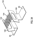
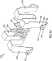
- the atomizer assembly 26 may include a wicking element 70, a heating element 100, and a wick housing 98. As explained in more detail below, at least a portion of the heating element 100 is positioned between the housing 7 and the wick housing 98 and is exposed to be coupled with a portion of the vaporizer body 50 (e.g., electrically coupled with the receptacle contacts 62).
- the wick housing 98 may include four sides.
- the wick housing 98 may include two opposing short sides and two opposing long sides. The two opposing long sides may each include at least one (two or more) recess 87 (see FIGS. 56 , 68A ).
- the recesses 87 may be positioned along the long side of the wick housing 98 and adjacent to respective intersections between the long sides and the short sides of the wick housing 98.
- the recesses 87 may be shaped to releasably couple with a corresponding feature (e.g., a spring) on the vaporizer body 50 to secure the vaporizer cartridge 52 to the vaporizer body 50 within the cartridge receptacle 69.
- the recesses 87 provides a mechanically stable securement means to couple the vaporizer cartridge 52 to the vaporizer body 50.
- the wick housing 98 also includes an identification chip 95, which may be configured to communicate with a corresponding chip reader located on the vaporizer.
- the identification chip 95 may be glued and/or otherwise adhered to the wick housing 98, such as on a short side of the wick housing 98.
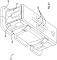
- the wick housing 98 may additionally or alternatively include a chip recess 83 (see FIG. 57 ) that is configured to receive the identification chip 95.
- the chip recess 83 may be surrounded by two, four, or more walls.
- the chip recess 83 may be shaped to secure the identification chip 95 to the wick housing 98.
- the vaporizer cartridge 52 may generally include a reservoir, an air path, and an atomizer 26.
- the heating element and/or atomizer described in accordance with implementations of the current subject matter can be implemented directly into a vaporizer body and/or may not be removable from the vaporizer body.
- the vaporizer body may not include a removable cartridge.
- a heating element of a vaporizer device may desirably be made (e.g., stamped) from a sheet of material and either crimped around at least a portion of a wicking element or bent to provide a preformed element configured to receive the wicking element (e.g., the wicking element is pushed into the heating element and/or the heating element is held in tension and is pulled over the wicking element).
- the heating element may be bent such that the heating element secures the wicking element between at least two or three portions of the heating element.
- the heating element may be bent to conform to a shape of at least a portion of the wicking element. Configurations of the heating element allows for more consistent and enhanced quality manufacturing of the heating element. Consistency of manufacturing quality of the heating element may be especially important during scaled and/or automated manufacturing processes. For example, the heating element consistent with implementations of the current subject matter helps to reduce tolerance issues that may arise during manufacturing processes when assembling a heating element having multiple components.
- accuracy of measurements taken from the heating element may be improved due at least in part to the improved consistency in manufacturability of the heating element having reduced tolerance issues. Greater accuracy in measurements can provide an enhanced user experience when using the vaporizer device.
- the vaporizer 10 may receive a signal to activate the heating element, either to a full operating temperature for creation of an inhalable dose of vapor/aerosol or to a lower temperature to begin heating the heating element.
- the temperature of the heating element of the vaporizer may depend on a number of factors, as noted above, and several of these factors can be made more predictable by elimination of potential variations in fabrication and assembly of atomizer components.
- a heating element made (e.g., stamped) from a sheet of material and either crimped around at least a portion of a wicking element or bent to provide a preformed element desirably helps to minimize heat losses and helps to ensure that the heating element behaves predictably to be heated to the appropriate temperature.
- the heating element may be entirely and/or selectively plated with one or more materials to enhance heating performance of the heating element.
- Plating all or a portion of the heating element may help to minimize heat losses.
- Plating may also help in concentrating the heated portion of the heating element in the proper location, providing a more efficiently heated heating element and further reducing heat losses.
- Selective plating may help to direct the current provided to the heating element to the proper location.
- Selective plating may also help to reduce the amount of plating material and/or costs associated with manufacturing the heating element.
- the heating element may be crimped around the wicking element and/or bent into the proper position to receive the wicking element.
- the wicking element may, in some implementations, be a fibrous wick, formed as an at least approximately flat pad or with other cross-sectional shapes such as circles, ovals, etc.
- a flat pad can allow for the rate that the vaporizable material is drawn into the wicking element to be controlled more precisely and/or accurately. For example, a length, width, and/or thickness can be adjusted for optimal performance.
- a wicking element forming a flat pad may also provide a greater transfer surface area, which may allow for increased flow of the vaporizable material from the reservoir into the wicking element for vaporization by the heating element (in other words, larger mass transfer of vaporizable material), and from the wicking element to air flowing past it.
- the heating element may contact the wicking element in multiple directions (e.g., on at least two sides of the wicking element) to increase efficiency of the process of drawing vaporizable material into the wicking element and vaporizing the vaporizable material.
- the flat pad may also be more easily shaped and/or cut, and thus may be more easily assembled with the heating element.
- the heating element may be configured to contact the wicking element on only one side of the wicking element.
- the wicking element may include one or more rigid or compressible materials, such as cotton, silica, ceramic, and/or the like. Relative to some other materials, a cotton wicking element may allow for an increased and/or more controllable flow rate of vaporizable material from the reservoir of the vaporizer cartridge into the wicking element to be vaporized.
- the wicking element forms an at least approximately flat pad that is configured to contact the heating element and/or be secured between at least two portions of the heating element.
- the at least approximately flat pad may have at least a first pair of opposing sides that are approximately parallel to one another.
- the at least approximately flat pad may also have at least a second pair of opposing sides that are approximately parallel to one another, and approximately perpendicular to the first pair of opposing sides.
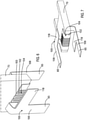
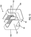
- FIGS. 2-5 illustrate schematic views of a heating element 100 consistent with implementations of the current subject matter.
- FIG. 2 illustrates a schematic view of a heating element 100 in an unfolded position. As shown, in the unfolded position, the heating element 100 forms a planar heating element.
- the heating element 100 may be initially formed of a substrate material. The substrate material is then cut and/or stamped into the proper shape via various mechanical processes, including but not limited to stamping, laser cutting, photo-etching, chemical etching, and/or the like.
- the substrate material may be made of an electrically conductive metal suitable for resistive heating.
- the heating element 100 includes a nickel-chromium alloy, a nickel alloy, stainless steel, and/or the like. As discussed below, the heating element 100 may be plated with a coating in one or more locations on a surface of the substrate material to enhance, limit, or otherwise alter the resistivity of the heating element in the one or more locations of the substrate material (which can be all or a portion of the heating element 100).
- the heating element 100 includes one or more tines 102 (e.g., heating segments) located in a heating portion 104, one or more legs or connecting portions 106 (e.g., one, two, or more) located in a transition region 108, and a cartridge contact 65 located in an electrical contact region 110 and formed at an end portion of each of the one or more legs 106.
- the tines 102, the legs 106, and the cartridge contacts 65 may be integrally formed.
- the tines 102, the legs 106, and the cartridge contacts 65 form portions of the heating element 100 that is stamped and/or cut from the substrate material.
- the heating element 100 also includes a heat shield 118 that extends from one or more of the legs 106 and also may be integrally formed with the tines 102, the legs 106, and the cartridge contacts 65.
- the heating portion 104 of the heating element 100 is configured to interface with the vaporizable material drawn into the wicking element from the reservoir 55 of the vaporizer cartridge 52.
- the heating portion 104 of the heating element 100 may be shaped, sized, and/or otherwise treated to create a desired resistance.
- the tines 102 located in the heating portion 104 may be designed so that the resistance of the tines 102 matches the appropriate amount of resistance to influence localized heating in the heating portion 104 to more efficiently and effectively heat the vaporizable material from the wicking element.
- the tines 102 form thin path heating segments or traces in series and/or in parallel to provide the desired amount of resistance.
- the tines 102 may include various shapes, sizes, and configurations. In some configurations, one or more of the tines 102 may be spaced to allow the vaporizable material to be wicked out of the wicking element and from there, vaporized off side edges of each of the tines 102.
- the shape, length, width, composition, etc., among other properties of the tines 102 may be optimized to maximize the efficiency of generating an aerosol by vaporizing vaporizable material from within the heating portion of the heating element 100 and to maximize electrical efficiency.
- the shape, length, width, composition, etc., among other properties of the tines 102 may additionally or alternatively be optimized to uniformly distribute heat across the length of the tines 102 (or a portion of the tines 102, such as at the heating portion 104).
- the width of the tines 102 may be uniform or variable along a length of the tines 102 to control the temperature profile across at least the heating portion 104 of the heating element 100.
- the length of the tines 102 may be controlled to achieve a desired resistance along at least a portion of the heating element 100, such as at the heating portion 104.
- the tines 102 each have the same size and shape.
- the tines 102 include an outer edge 103 that is approximately aligned and have a generally rectangular shape, with flat or squared outer edges 103 (see also FIGS. 6-10 , and) or rounded outer edges 103 (see FIGS. 11 and 12 ).
- one or more of the tines 102 may include outer edges 103 that are not aligned and/or may be differently sized or shaped (see FIGS. 14-19 ).
- the tines 102 may be evenly spaced or have variable spacing between adjacent tines 102 (see FIGS. 44-49 ).
- the particular geometry of the tines 102 may be desirably selected to produce a particular localized resistance for heating the heating portion 104, and to maximize performance of the heating element 100 to heat the vaporizable material and generate an aerosol.
- the heating element 100 may include portions of wider and/or thicker geometry, and/or differing composition relative to the tines 102. These portions may form electrical contact areas and/or more conductive parts, and/or may include features for mounting the heating element 100 within the vaporizer cartridge.
- the legs 106 of the heating element 100 extend from an end of each outermost tine 102A. The legs 106 form a portion of the heating element 100 that has a width and/or thickness that is typically wider than a width of each of the tines 102. Though, in some implementations, the legs 106 have a width and/or thickness that is the same as or narrower than the width of each of the tines 102.
- the legs 106 couple the heating element 100 to the wick housing 98 or another portion of the vaporizer cartridge 52, so that the heating element 100 is at least partially or fully enclosed by the housing 7.
- the legs 106 provide rigidity to encourage the heating element 100 to be mechanically stable during and after manufacturing.
- the legs 106 also connect the cartridge contacts 65 with the tines 102 located in the heating portion 104.
- the legs 106 are shaped and sized to allow the heating element 100 to maintain the electrical requirements of the heating portion 104. As shown in FIG. 5 , the legs 106 space the heating portion 104 from an end of the vaporizer cartridge 52 when the heating element 100 is assembled with the vaporizer cartridge 52.
- the legs 106 may also include a capillary feature 198, which limits or prevents fluid from flowing out of the heating portion 104 to other portions of the heating element 100.
- one or more of the legs 106 includes one or more locating features 116.
- the locating features 116 may be used for relative locating of the heating element 100 or portions thereof during and/or after assembly by interfacing with other (e.g., adjacent) components of the vaporizer cartridge 52.
- the locating features 116 may be used during or after manufacturing to properly position the substrate material for cutting and/or stamping the substrate material to form the heating element 100 or post-processing of the heating element 100.
- the locating features 116 may be sheared off and/or cut off before crimping or otherwise bending the heating element 100.
- the heating element 100 includes one or more heat shields 118.
- the heat shields 118 form a portion of the heating element 100 that extends laterally from the legs 106. When folded and/or crimped, the heat shields 118 are positioned offset in a first direction and/or a second direction opposite the first direction in the same plane from the tines 102.
- the heat shields 118 are configured to be positioned between the tines 102 (and the heating portion 104) and the body (e.g., plastic body) of the vaporizer cartridge 52.
- the heat shields 118 can help to insulate the heating portion 104 from the body of the vaporizer cartridge 52.
- the heat shields 118 help to minimize the effects of the heat emanating from the heating portion 104 on the body of the vaporizer cartridge 52 to protect the structural integrity of the body of the vaporizer cartridge 52 and to prevent melting or other deformation of the vaporizer cartridge 52.
- the heat shields 118 may also help to maintain a consistent temperature at the heating portion 104 by retaining heat within the heating portion 104, thereby preventing or limiting heat losses while vaporization is occurring.
- the vaporizer cartridge 52 may also or alternatively include a heat shield 118A that is separate from the heating element 100 (see FIG. 59 ).
- the heating element 100 includes at least two cartridge contacts 65 that form an end portion of each of the legs 106.
- the cartridge contacts 65 may form the portion of the legs 106 that is folded along a fold line 107.
- the cartridge contacts 65 may be folded at an angle of approximately 90 degrees relative to the legs 106.
- the cartridge contacts 65 may be folded at other angles, such as at an angle of approximately 15 degrees, 25 degrees, 35 degrees, 45 degrees, 55 degrees, 65 degrees, 75 degrees or other ranges therebetween, relative to the legs 106.
- the cartridge contacts 65 may be folded towards or away from the heating portion 104, depending on the implementation.
- the cartridge contacts 65 may also be formed on another portion of the heating element 100, such as along a length of at least one of the legs 106.
- the cartridge contacts 65 are configured to be exposed to the environment when assembled in the vaporizer cartridge 52 (see FIG. 10 ).
- the cartridge contacts 65 may form conductive pins, tabs, posts, receiving holes, or surfaces for pins or posts, or other contact configurations. Some types of cartridge contacts 65 may include springs or other urging features to cause better physical and electrical contact between the cartridge contacts 65 on the vaporizer cartridge and receptacle contacts 62 on the vaporizer body 50.
- the cartridge contacts 65 include wiping contacts that are configured to clean the connection between the cartridge contacts 65 and other contacts or power source.
- the wiping contacts would include two parallel, but offset, bosses that frictionally engage and slide against one another in a direction that is parallel or perpendicular to the insertion direction.
- the cartridge contacts 65 are configured to interface with the receptacle contacts 62 disposed near a base of the cartridge receptacle of the vaporizer 10 such that the cartridge contacts 65 and the receptacle contacts 62 make electrical connections when the vaporizer cartridge 52 is inserted into and coupled with the cartridge receptacle 69.
- the cartridge contacts 65 may electrically communicate with the power source 8 of the vaporizer device (such as via the receptacle contacts 62, etc.).
- the circuit completed by these electrical connections can allow delivery of electrical current to the resistive heating element to heat at least a portion of the heating element 100 and may further be used for additional functions, such as for example for measuring a resistance of the resistive heating element for use in determining and/or controlling a temperature of the resistive heating element based on a thermal coefficient of resistivity of the resistive heating element, for identifying a cartridge based on one or more electrical characteristics of a resistive heating element or the other circuitry of the vaporizer cartridge, etc.
- the cartridge contacts 65 may be treated, as explained in more detail below, to provide improved electrical properties (e.g., contact resistance) using, for example, conductive plating, surface treatment, and/or deposited materials.
- the heating element 100 may be processed through a series of crimping and/or bending operations to shape the heating element 100 into a desired three-dimensional shape.
- the heating element 100 may be preformed to receive or crimped about a wicking element 70 to secure the wicking element between at least two portions (e.g., approximately parallel portions) of the heating element 100 (such as between opposing portions of the heating portion 104).
- the heating element 100 may be bent along fold lines 120 towards one another. Folding the heating element 100 along fold lines 120 forms a platform tine portion 124 defined by the region between the fold lines 120 and side tine portions 126 defined by the region between the fold lines 120 and the outer edges 103 of the tines 102.
- the platform tine portion 124 is configured to contact one end of the wicking element 70.
- the side tine portions 126 are configured to contact opposite sides of the wicking element 70.
- the platform tine portion 124 and the side tine portions 126 form a pocket that is shaped to receive the wicking element 70 and/or conform to the shape of at least a portion of the wicking element 70.
- the pocket allows the wicking element 70 to be secured and retained by the heating element 100 within the pocket.
- the platform tine portion 124 and the side tine portions 126 contact the wicking element 70 to provide a multi-dimensional contact between the heating element 100 and the wicking element 70.
- Multi-dimensional contact between the heating element 100 and the wicking element 70 provides for a more efficient and/or faster transfer of the vaporizable material from the reservoir 55 of the vaporizer cartridge 52 to the heating portion 104 (via the wicking element 70) to be vaporized.
- portions of the legs 106 of the heating element 100 may also be bent along fold lines 122 away from one another. Folding the portions of the legs 106 of the heating element 100 along fold lines 122 away from one another locates the legs 106 at a position spaced away from the heating portion 104 (and tines 102) of the heating element 100 in a first and/or second direction opposite the first direction (e.g., in the same plane). Thus, folding the portions of the legs 106 of the heating element 100 along fold lines 122 away from one another spaces the heating portion 104 from the body of the vaporizer cartridge 52.
- FIG. 3 illustrates a schematic of the heating element 100 that has been folded along the fold lines 120 and fold lines 122 about the wicking element 70. As shown in FIG. 3 , the wicking element is positioned within the pocket formed by folding the heating element 100 along fold lines 120 and 122.
- the heating element 100 may also be bent along fold lines 123.
- the cartridge contacts 65 may be bent towards one another (into and out of the page shown in FIG. 4 ) along the fold lines 123.
- the cartridge contacts 65 may be exposed to the environment to contact the receptacle contacts, while the remaining portions of the heating element 100 are positioned within the vaporizer cartridge 52 (see FIGS. 5 and 10 ).
- the heating element 100 may be activated, e.g., by automatic detection of the puff via a pressure sensor, by detection of a pushing of a button by the user, by signals generated from a motion sensor, a flow sensor, a capacitive lip sensor, and/or another approach capable of detecting that a user is taking or about to be taking a puff or otherwise inhaling to cause air to enter the vaporizer device 10 and travel at least along the air path.
- Power can be supplied from the vaporizer device to the heating element 100 at the cartridge contacts 65, when the heating element 100 is activated.
- the heating element 100 When the heating element 100 is activated, a temperature increase results due to current flowing through the heating element 100 to generate heat.
- the heat is transferred to some amount of the vaporizable material through conductive, convective, and/or radiative heat transfer such that at least a portion of the vaporizable material vaporizes.
- the heat transfer can occur to vaporizable material in the reservoir and/or to vaporizable material drawn into the wicking element 70 retained by the heating element 100.
- the vaporizable material can vaporize along one or more edges of the tines 102, as mentioned above.
- the air passing into the vaporizer device flows along the air path across the heating element 100, stripping away the vaporized vaporizable material from the heating element 100.
- the vaporized vaporizable material can be condensed due to cooling, pressure changes, etc., such that it exits the mouthpiece 21 as an aerosol for inhalation by a user.
- the heating element 100 may be made of various materials, such as nichrome, stainless steel, or other resistive heater materials. Combinations of two or more materials may be included in the heating element 100, and such combinations can include both homogeneous distributions of the two or more materials throughout the heating element or other configurations in which relative amounts of the two or more materials are spatially heterogeneous.
- the tines 102 may have portions that are more resistive and thereby be designed to grow hotter than other sections of the tines or heating element 100.
- at least the tines 102 (such as within the heating portion 104) may include a material that has high conductivity and heat resistance.
- the heating element 100 may be entirely or selectively plated with one or more materials. Since the heating element 100 is made of a thermally and/or electrically conductive material, such as stainless steel, nichrome, or other thermally and/or electrically conductive alloy, the heating element 100 may experience electrical or heating losses in the path between the cartridge contacts 65 and the tines 102 in the heating portion 104 of the heating element 100. To help to reduce heating and/or electrical losses, at least a portion of the heating element 100 may be plated with one or more materials to reduce resistance in the electrical path leading to the heating portion 104.
- the heating portion 104 e.g., the tines 102
- the heating portion 104 to remain unplated, with at least a portion of the legs 106 and/or cartridge contacts 65 being plated with a plating material that reduces resistance (e.g., either or both of bulk and contact resistance) in those portions.
- the heating element 100 may include various portions that are plated with different materials.
- the heating element 100 may be plated with layered materials. Plating at least a portion of the heating element 100 helps to concentrate current flowing to the heating portion 104 to reduce electrical and/or heat losses in other portions of the heating element 100. In some implementations, it is desirable to maintain a low resistance in the electrical path between the cartridge contacts 65 and the tines 102 of the heating element 100 to reduce electrical and/or heat losses in the electrical path and to compensate for the voltage drop that is concentrated across the heating portion 104.
- the cartridge contacts 65 may be selectively plated. Selectively plating the cartridge contacts 65 with certain materials may minimize or eliminate contact resistance at the point where the measurements are taken and the electrical contact is made between the cartridge contacts 65 and the receptacle contacts. Providing a low resistance at the cartridge contacts 65 can provide more accurate voltage, current, and/or resistance measurements and readings, which can be beneficial for accurately determining the current actual temperature of the heating portion 104 of the heating element 100.
- At least a portion of the cartridge contacts 65 and/or at least a portion of the legs 106 may be plated with one or more outer plating materials 150.
- at least a portion of the cartridge contacts 65 and/or at least a portion of the legs 106 may be plated with at least gold, or another material that provides low contact resistance, such as platinum, palladium, silver, copper, or the like.
- a surface of the heating element 100 may be plated with an adhering plating material.
- the adhering plating material may be deposited onto the surface of the heating element 100 and the outer plating material may be deposited onto the adhering plating material, defining first and second plating layers, respectively.
- the adhering plating material includes a material with adhesive properties when the outer plating material is deposited onto the adhering plating material.
- the adhering plating material may include nickel, zinc, aluminum, iron, alloys thereof, or the like.
- FIGS. 36-38 illustrate examples of the heating element 100 in which the cartridge contacts 65 have been selectively plated with the adhering plating material and/or the outer plating material.
- the surface of the heating element 100 may be primed for the outer plating material to be deposited onto the heating element 100 using non-plating priming, rather than by plating the surface of the heating element 100 with the adhering plating material.
- the surface of the heating element 100 may be primed using etching rather than by depositing the adhering plating material.
- all or a portion of the legs 106 and the cartridge contacts 65 may be plated with the adhering plating material and/or the outer plating material.
- the cartridge contacts 65 may include at least a portion that has an outer plating material having a greater thickness relative to the remaining portions of the cartridge contacts 65 and/or the legs 106 of the heating element 100.
- the cartridge contacts 65 and/or the legs 106 may have a greater thickness relative to the tines 102 and/or the heating portion 104.
- the heating element 100 may be formed of various materials that are coupled together (e.g., via laser welding, diffusion processes, etc.). The materials of each portion of the heating element 100 that is coupled together may be selected to provide a low or no resistance at the cartridge contacts 65 and a high resistance at the tines 102 or heating portion 104 relative to the other portions of the heating element 100.
- the heating element 100 may be electroplated with silver ink and/or spray coated with one or more plating materials, such as the adhering plating material and the outer plating material.
- the heating element 100 may include various shapes, sizes, and geometries to more efficiently heat the heating portion 104 of the heating element 100 and more efficiently vaporize the vaporizable material.
- FIGS. 6-10 illustrate an example of a heating element 100 consistent with implementations of the current subject matter.
- the heating element 100 includes the one or more tines 102 located in the heating portion 104, the one or more legs 106 extending from the tines 102, the cartridge contacts 65 formed at the end portion of each of the one or more legs 106, and the heat shields 118 extending from the one or more legs 106.
- each of the tines 102 have the same or similar shape and size.
- the tines 102 have a squared and/or flat outer edge 103.
- the tines 102 have been crimped about a wicking element 70 (e.g., a flat pad) to secure the wicking element 70 within the pocket of the tines 102.
- a wicking element 70 e.g., a flat pad
- FIGS. 11-12 illustrate another example of a heating element 100 consistent with implementations of the current subject matter in an unbent position ( FIG. 11 ) and a bent position ( FIG. 12 ).
- the heating element 100 includes the one or more tines 102 located in the heating portion 104, the one or more legs 106 extending from the tines 102, the cartridge contacts 65 formed at the end portion of each of the one or more legs 106, and the heat shields 118 extending from the one or more legs 106.
- each of the tines 102 have the same or similar shape and size and the tines 102 have a rounded and/or semicircular outer edge 103.
- FIG. 13 illustrates another example of a heating element 100 in a bent position consistent with implementations of the current subject matter that is similar to the example heating element 100 shown in FIGS. 11-12 , but in this example, each of the tines 102 have the same or similar shape and size and the tines 102 have a squared and/or flat outer edge 103.
- FIGS. 14-19 illustrate other examples of the heating element 100 in which at least one of the tines 102 has a size, shape, or position that is different from the remaining tines 102.
- the heating element 100 includes the one or more tines 102 located in the heating portion 104, the one or more legs 106 extending from the tines 102, and the cartridge contacts 65 formed at the end portion of each of the one or more legs 106.
- the tines 102 include a first set of tines 105A and a second set of tines 105B. The first and second sets of tines 105A, 105B are offset from one another.
- the outer edges 103 of the first and second sets of tines 105A, 105B are not aligned with one another. As shown in FIG. 15 , when the heating portion 104 is in the bent position, the first set of tines 105A appear to be shorter than the second set of tines 105B in the first portion of the heating element 100, and the first set of tines 105A appear to be longer than the second set of tines 105B in the second portion of the heating element 100.
- the heating element 100 includes the one or more tines 102 located in the heating portion 104, the one or more legs 106 extending from the tines 102, and the cartridge contacts 65 formed at the end portion of each of the one or more legs 106.
- the tines 102 include a first set of tines 109A and a second set of tines 109B.
- the first and second sets of tines 109A, 109B are offset from one another.
- the outer edges 103 of the first and second sets of tines 109A, 109B are not aligned with one another.
- the second set of tines 109B includes a single outermost tine 102A. As shown in FIGS.
- the first set of tines 109A appear to be longer than the second set of tines 109B.
- the tines 102 are not bent. Rather, the tines 102 are located on a first portion and a second portion of the heating element 100 that is positioned approximately parallel to and opposite the first portion.
- the first set of tines positioned on the first portion of the heating element 100 are separated from the second set of tines positioned on the second portion of the heating element 100 by a platform portion 130 that is positioned between and spaced from both of the first and second set of tines.
- the platform portion 130 is configured to contact an end of the wicking element 70.
- the platform portion 130 includes a cutout portion 132.
- the cutout portion 132 may provide additional edges along which the vaporizable material can vaporize from when the heating element 100 is activated.
- the heating element 100 includes the one or more tines 102 located in the heating portion 104, the one or more legs 106 extending from the tines 102, and the cartridge contacts 65 formed at the end portion of each of the one or more legs 106.
- the tines 102 include a first set of tines 109A and a second set of tines 109B.
- the first and second sets of tines 109A, 109B are offset from one another.
- the outer edges 103 of the first and second sets of tines 109A, 109B are not aligned with one another.
- each of the first and the second set of tines 109A, 109B includes two tines 102. As shown in FIGS.
- the first set of tines 109A appear to be shorter than the second set of tines 109B.
- the tines 102 are not bent. Rather, the tines 102 are located on a first portion and a second portion (that is parallel and opposite the first portion) of the heating element 100.
- the first set of tines positioned on the first portion are separated from the second set of tines positioned on the second portion by a platform portion that is positioned between and spaced from both of the first and second set of tines.
- the platform portion is configured to contact an end of the wicking element 70.
- the platform portion includes a cutout portion. The cutout portion may provide additional edges along which the vaporizable material can vaporize from when the heating element 100 is activated.
- FIGS. 20-25 illustrate another example of a heating element 100 not covered by the claims and consistent with implementations of the current subject matter in an unbent position ( FIG. 20 ) and a bent position ( FIGS. 21-25 ).
- the heating element 100 includes the one or more tines 102 located in the heating portion 104, the one or more legs 106 extending from the tines 102, the cartridge contacts 65 formed at the end portion of each of the one or more legs 106, and the heat shields 118 extending from the one or more legs 106.
- the heating element 100 is configured to be crimped around and/or bent to receive a cylindrical-shaped wicking element 70 or a wicking element 70 having a circular cross-section.
- Each of the tines 102 include apertures 140.
- the apertures 140 may provide additional edges along which the vaporizable material can vaporize from when the heating element 100 is activated.
- the apertures 140 also reduce the amount of material used to form the heating element 100, reducing the weight of the heating element 100 and the amount of material used for the heating element 100, thereby reducing material costs.
- FIGS. 26-35 illustrate a heating element 100 not covered by the claims and consistent with implementations of the current subject matter in which the heating element 100 is pressed against one side of the wicking element 70.
- the heating element 100 includes the one or more tines 102 located in the heating portion 104, the one or more legs 106 extending from the tines 102, and the cartridge contacts 65 formed at the end portion of each of the one or more legs 106.
- the legs 106 and the cartridge contacts 65 are configured to bend in a third direction, rather than in a first-second direction that is perpendicular to the third direction.
- the tines 102 of the heating portion 104 form a planar platform that faces outwardly from the heating element 100 and is configured to be pressed against the wicking element 70 (e.g., on one side of the wicking element 70).
- FIGS. 28-31 illustrate several examples of the heating element 100 not covered by the claims and consistent with implementations of the current subject matter including tines 102 configured in various geometries. As mentioned above, the tines 102 form a planar platform that is pressed against one side of the wicking element 70 in use. The legs 106, rather than the tines 102, bend in the bent position.
- FIG. 32 illustrates an example of the heating element 100 shown in FIG. 28 assembled with a component of the vaporizer cartridge 52, such as a wick housing (e.g., the wick housing 98) that houses the wicking element 70 and the heating element 100 and
- FIG. 33 illustrates the heating element 100 assembled with an example vaporizer cartridge 52 consistent with implementations of the current subject matter. As shown the cartridge contacts 65 are bent towards one another in a lateral direction.
- FIGS. 34 and 35 illustrate another example of the heating element 100 not covered by the claims in which the tines 102 form a platform that is configured to be pressed against the wicking element 70.
- the legs 106 may form spring-like structures that force the tines 102 to be pressed against the wicking element 70 when a lateral inward force is applied to each of the legs 106.
- FIG. 35 illustrates an example of the tines 102 being pressed against the wicking element 70 when power (e.g., a current) is supplied to the heating element 100, such as via the cartridge contacts 65.
- power e.g., a current
- FIGS. 39-43 illustrate another example of a heating element 100 consistent with implementations of the current subject matter.
- the heating element 100 includes the one or more tines 102 located in the heating portion 104, the one or more legs 106 extending from the tines 102, and the cartridge contacts 65 formed at the end portion and/or as part of each of the one or more legs 106.
- each of the tines 102 have the same or similar shape and size, and are spaced apart from one another at equal distances.
- the tines 102 have a rounded outer edge 103.
- the tines 102 have been crimped about a wicking element 70 (e.g., a flat pad) to secure the wicking element 70 within the pocket formed by the tines 102.
- the tines 102 may be folded and/or crimped to define the pocket in which the wicking element 70 resides.
- the tines 102 include a platform tine portion 124 and side tine portions 126.
- the platform tine portion 124 is configured to contact one side of the wicking element 70 and the side tine portions 126 are configured to contact other opposite sides of the wicking element 70.
- the platform tine portion 124 and the side tine portions 126 form the pocket that is shaped to receive the wicking element 70 and/or conform to the shape of at least a portion of the wicking element 70.
- the pocket allows the wicking element 70 to be secured and retained by the heating element 100 within the pocket.
- the side tine portions 126 and the platform tine portion 124 retain the wicking element 70 via compression (e.g., at least a portion of the wicking element 70 is compressed between the opposing side tine portions 126 and/or the platform tine portion 124).
- the platform tine portion 124 and the side tine portions 126 contact the wicking element 70 to provide a multi-dimensional contact between the heating element 100 and the wicking element 70.
- Multi-dimensional contact between the heating element 100 and the wicking element 70 provides for a more efficient and/or faster transfer of the vaporizable material from the reservoir 55 of the vaporizer cartridge 52 to the heating portion 104 (via the wicking element 70) to be vaporized.
- the one or more legs 106 of the example heating element 100 shown in FIGS. 39-43 includes four legs 106.
- Each of the legs 106 may include and/or define a cartridge contact 65 that is configured to contact a corresponding receptacle contact 62 of the vaporizer 10.
- each pair of legs 106 (and the cartridge contacts 65) may contact a single receptacle contact 62.
- the legs 106 may be spring-loaded to allow the legs 106 to maintain contact with the receptacle contacts 62.
- the legs 106 may include a portion that extends along a length of the legs 106 that is curved to help to maintain contact with the receptacle contacts 62.
- Spring-loading the legs 106 and/or the curvature of the legs 106 may help to increase and/or maintain consistent pressure between the legs 106 and the receptacle contacts 62.
- the legs 106 are coupled with a support 97 that helps to increase and/or maintain consistent pressure between the legs 106 and the receptacle contacts 62.
- the support 97 may include plastic, rubber, or other materials to help maintain contact between the legs 106 and the receptacle contacts 62.
- the support 97 is formed as a part of the legs 106.
- the legs 106 may contact one or more wiping contacts that are configured to clean the connection between the cartridge contacts 65 and other contacts or power source.
- the wiping contacts would include at least two parallel, but offset, bosses that frictionally engage and slide against one another in a direction that is parallel or perpendicular to the insertion direction.
- the one or more legs 106 of the heating element 100 includes four legs 106.
- FIGS. 48-49 , 54A-55B , and 66-67 show examples of the heating element 100 in the unbent position.
- the heating element 100 has an H-shape, defined by the four legs 106 and the tines 102. This configuration allows for resistance across the heater to be measured more accurately, and reduces variability in the resistance measurements, thereby allowing for more efficiency aerosol generation and higher quality aerosol generation.
- the heating element 100 includes two pairs of opposing legs 106.
- the tines 102 are coupled (e.g., intersect) with each of the pairs of opposing legs 106 at or near a center of each of the pairs of opposing legs 106.
- the heating portion 104 is positioned between the pairs of opposing legs 106.
- FIG. 66 illustrates an example of the heating element 100 before the heating element 100 has been stamped and/or otherwise formed from a substrate material 177.
- Excess substrate material 177A may be coupled with the heating element 100 at one, two, or more coupling locations 177B.
- the excess substrate material 177A may be coupled with the heating element 100 at two coupling locations 177B, near opposing lateral ends 173 of the platform portion of the heating element and/or heating portion 104 of the heating element 100.
- the heating element 100 may be first be stamped from the substrate material 177, and then removed from the excess substrate material 177A at the coupling locations 177B (e.g., by twisting, pulling, stamping, cutting, etc., the heating element 100).
- the heating element 100 may be bent or otherwise folded along fold lines 123, 122A, 122B, 120 towards or away from one another (see, for example, FIG. 55A ). Though the fold lines are illustrated in FIG. 55A , the example heating elements 100 described and shown in FIGS. 1D-72C may also be crimped, folded, or otherwise bent along the fold lines. Folding the heating element 100 along fold lines 120 forms a platform tine portion 124 defined by the region between the fold lines 120 and/or between side tine portions 126 defined by the region between the fold lines 120 and the outer edges 103 of the tines 102. The platform tine portion 124 may contact one end and/or support one end of the wicking element 70.
- the side tine portions 126 may contact opposite sides of the wicking element 70.
- the platform tine portion 124 and the side tine portions 126 define an interior volume of the heating element that forms a pocket shaped to receive the wicking element 70 and/or conform to the shape of at least a portion of the wicking element 70.
- the interior volume allows the wicking element 70 to be secured and retained by the heating element 100 within the pocket.
- the platform tine portion 124 and the side tine portions 126 contact the wicking element 70 to provide a multi-dimensional contact between the heating element 100 and the wicking element 70.
- Multi-dimensional contact between the heating element 100 and the wicking element 70 provides for a more efficient and/or faster transfer of the vaporizable material from the reservoir 55 of the vaporizer cartridge 52 to the heating portion 104 (via the wicking element 70) to be vaporized.
- portions of the legs 106 of the heating element 100 may also be bent along fold lines 122A, 122B. Folding the portions of the legs 106 of the heating element 100 along fold lines 122 away from one another locates the legs 106 at a position spaced away from the heating portion 104 (and tines 102) of the heating element 100 in a first and/or second direction opposite the first direction (e.g., in the same plane). Thus, folding the portions of the legs 106 of the heating element 100 along fold lines 122 away from one another spaces the heating portion 104 from the body of the vaporizer cartridge 52. Folding the portions of the legs 106 along the fold lines 122A, 122B forms a bridge 185.
- the bridge 185 helps to reduce or eliminate overflow of vaporizable material from the heating portion 104, such as due to capillary action.
- the bridge 185 also helps to isolate the heating portion 104 from the legs 106, so that the heat generated at the heating portion 104 does not reach the legs 106. This also helps to localize heating of the heating element 100 to within the heating portion 104.
- the heating element 100 may also be bent along fold lines 123 to define the cartridge contacts 65.
- the cartridge contacts 65 may be exposed to the environment or may otherwise be accessible (and may be positioned within an interior of a portion of the cartridge, such as the outer shell) to contact the receptacle contacts, while other portions, such as the heating portion 104 of the heating element 100, are positioned within an inaccessible part of the vaporizer cartridge 52, such as the wick housing.
- the legs 106 include retainer portions 99 that are configured to be bent around at least a portion of a wick housing 98 that surrounds at least a portion of the wicking element 70 and heating element 100 (such as the heating portion 104).
- the retainer portions 99 form an end of the legs 106.
- the retainer portions 99 help to secure the heating element 100 and wicking element 70 to the wick housing 98 (and the vaporizer cartridge 52).
- the retainer portions 99 may alternatively be bent away from at least a portion of the wick housing 98.
- FIGS. 44-49 illustrate another example of a heating element 100 consistent with implementations of the current subject matter.
- the heating element 100 includes the one or more tines 102 located in the heating portion 104, the one or more legs 106 extending from the tines 102, and the cartridge contacts 65 formed at the end portion and/or as part of each of the one or more legs 106.
- the tines 102 may be folded and/or crimped to define the pocket in which a wicking element 70 (e.g., a flat pad) resides.
- the tines 102 include a platform tine portion 124 and side tine portions 126.
- the platform tine portion 124 is configured to contact one side of the wicking element 70 and the side tine portions 126 are configured to contact other opposite sides of the wicking element 70.
- the platform tine portion 124 and the side tine portions 126 form the pocket that is shaped to receive the wicking element 70 and/or conform to the shape of at least a portion of the wicking element 70.
- the pocket allows the wicking element 70 to be secured and retained by the heating element 100 within the pocket.
- each of the side tine portions 126 includes at least four tines 102.
- each of the adjacent tines 102 is spaced apart at an equal distance from an inner region 176 positioned near the platform tine portion 124 to an outer region 178 positioned near the outer edge 103.
- the adjacent tines 102 are spaced apart by a varying distance from the inner region 176 to the outer region 178.
- the adjacent tines 102 of the second pair 172 are spaced apart by a width that is greater at the inner region 176 than at the outer region 178. These configurations may help to maintain a constant and uniform temperature along the length of the tines 102 of the heating portion 104. Maintaining a constant temperature along the length of the tines 102 may provide higher quality aerosol, as the maximum temperature is more uniformly maintainable across the entire heating portion 104.
- each of the legs 106 may include and/or define a cartridge contact 65 that is configured to contact a corresponding receptacle contact 62 of the vaporizer 10.
- each pair of legs 106 (and the cartridge contacts 65) may contact a single receptacle contact 62.
- the legs 106 include retainer portions 99 that are configured to be bent and generally extend away from the heating portion 104.
- the retainer portions 99 are configured to be positioned within a corresponding recess in the wick housing 98.
- the retainer portions 99 form an end of the legs 106.
- the retainer portions 99 help to secure the heating element 100 and wicking element 70 to the wick housing 98 (and the vaporizer cartridge 52).
- the retainer portions 99 may have a tip portion 99A that extends from an end of the retainer portion 99 towards the heating portion 104 of the heating element 100. This configuration reduces the likelihood that the retainer portion will contact another portion of the vaporizer cartridge 52, or a cleaning device for cleaning the vaporizer cartridge 52.
- the outer edge 103 of the tines 102 in the heating portion 104 may include a tab 180.
- the tab 180 may include one, two, three, four, or more tabs 180.
- the tab 180 may extend outwardly from the outer edge 103 and extend away from a center of the heating element 100.
- the tab 180 may be positioned along an edge of the heating element 100 surrounding an internal volume defined by at least the side tine portions 126 for receiving the wicking element 70.
- the tab 180 may extend outwardly away from the internal volume of the wicking element 70.
- the tab 180 may also extend away in a direction opposite the platform tine portion 124.
- tabs 180 positioned on opposing sides of the internal volume of the wicking element 70 may extend away from one another.
- This configuration helps to widen the opening leading to the internal volume of the wicking element 70, thereby helping to reduce the likelihood that the wicking element 70 will catch, tear, and/or become damaged when assembled with the heating element 100. Due to the material of the wicking element 70, the wicking element 70 may easily catch, tear, and/or otherwise become damaged when assembled (e.g., positioned within or inserted into) with the heating element 100. Contact between the wicking element 70 and the outer edge 103 of the tines 102 may also cause damage to the heating element.
- the shape and/or positioning of the tab 180 may allow the wicking element 70 to more easily be positioned within or into the pocket (e.g., the internal volume of the heating element 100) formed by the tines 102, thereby preventing or reducing the likelihood that the wicking element 70 and/or the heating element will be damaged.
- the tabs 180 help to reduce or prevent damage caused to the heating element 100 and/or the wicking element 70 upon entry of the wicking element 70 into thermal contact with the heating element 100.
- the shape of the tab 180 also helps to minimize impact on the resistance of the heating portion 104.
- At least a portion of the cartridge contacts 65 and/or at least a portion of the legs 106 may be plated with one or more outer plating materials 150 to reduce contact resistance at the point where the heating element 100 contacts the receptacle contacts 62.
- FIGS. 50A-55B illustrate another example of a heating element 100 consistent with implementations of the current subject matter.
- the heating element 100 includes the one or more tines 102 located in the heating portion 104, the one or more legs 106 extending from the tines 102, and the cartridge contacts 65 formed at the end portion and/or as part of each of the one or more legs 106.
- the tines 102 may be folded and/or crimped to define the pocket in which a wicking element 70 (e.g., flat pad) resides.
- the tines 102 include a platform tine portion 124 and side tine portions 126.
- the platform tine portion 124 is configured to contact one side of the wicking element 70 and the side tine portions 126 are configured to contact other opposite sides of the wicking element 70.
- the platform tine portion 124 and the side tine portions 126 form the pocket that is shaped to receive the wicking element 70 and/or conform to the shape of at least a portion of the wicking element 70.
- the pocket allows the wicking element 70 to be secured and retained by the heating element 100 within the pocket.
- the tines 102 have the same shape and size and are spaced apart from one another at equal distances.
- the tines 102 include a first side tine portion 126A and a second side tine portion 126B that are spaced apart by the platform tine portion 124.
- Each of the first and second side tine portions 126A, 126B include an inner region 176 positioned near the platform tine portion 124 to an outer region 178 positioned near the outer edge 103.
- the first side tine portion 126A is positioned approximately parallel to the second tine portion 126B.
- the first side tine portion 126A is positioned offset from the second tine portion 126B and the first and second side tine portions 126A, 126B are not parallel.
- This configuration may help to maintain a constant and uniform temperature along the length of the tines 102 of the heating portion 104. Maintaining a constant temperature along the length of the tines 102 may provide higher quality aerosol, as the maximum temperature is more uniformly maintainable across the entire heating portion 104.
- each of the legs 106 may include and/or define a cartridge contact 65 that is configured to contact a corresponding receptacle contact 62 of the vaporizer 10.
- each pair of legs 106 (and the cartridge contacts 65) may contact a single receptacle contact 62.
- the legs 106 include retainer portions 99 that are configured to be bent and generally extend away from the heating portion 104.
- the retainer portions 99 are configured to be positioned within a corresponding recess in the wick housing 98.
- the retainer portions 99 form an end of the legs 106.
- the retainer portions 99 help to secure the heating element 100 and wicking element 70 to the wick housing 98 (and the vaporizer cartridge 52).
- the retainer portions 99 may have a tip portion 99A that extends from an end of the retainer portion 99 towards the heating portion 104 of the heating element 100. This configuration reduces the likelihood that the retainer portion will contact another portion of the vaporizer cartridge 52, or a cleaning device for cleaning the vaporizer cartridge 52.
- the outer edge 103 of the tines 102 in the heating portion 104 may include a tab 180.
- the tab 180 may extend outwardly from the outer edge 103 and extend away from a center of the heating element 100.
- the tab 180 may be shaped to allow the wicking element 70 to more easily be positioned within the pocket formed by the tines 102, thereby preventing or reducing the likelihood that the wicking element 70 will get caught on the outer edge 103.
- the shape of the tab 180 helps to minimize impact on the resistance of the heating portion 104.
- At least a portion of the cartridge contacts 65 and/or at least a portion of the legs 106 may be plated with one or more outer plating materials 150 to reduce contact resistance at the point where the heating element 100 contacts the receptacle contacts 65.
- FIGS. 56-57 illustrate an example of the atomizer assembly 26, with the heating element 100 assembled with the wick housing 98
- FIG. 58 illustrates an exploded view of the atomizer assembly 26, consistent with implementations of the current subject matter.
- the wick housing 98 may be made of plastic, polypropylene, and the like.
- the wick housing 98 includes four recesses 192 in which at least a portion of each of the legs 106 of the heating element 100 may be positioned and secured.
- the wick housing 98 also includes an opening 193 providing access to an internal volume 194, in which at least the heating portion 104 of the heating element 100 and the wicking element 70 are positioned.
- the wick housing 98 may also include a separate heat shield 118A, which is shown in FIG. 59 .
- the heat shield 118A is positioned within the internal volume 194 within the wick housing 98 between the walls of the wick housing 98 and the heating element 100.
- the heat shield 118A is shaped to at least partially surround the heating portion 104 of the heating element 100 and to space the heating element 100 from the side walls of the wick housing 98.
- the heat shield 118A can help to insulate the heating portion 104 from the body of the vaporizer cartridge 52 and/or the wick housing 98.
- the heat shield 118A helps to minimize the effects of the heat emanating from the heating portion 104 on the body of the vaporizer cartridge 52 and/or the wick housing 98 to protect the structural integrity of the body of the vaporizer cartridge 52 and/or the wick housing 98 and to prevent melting or other deformation of the vaporizer cartridge 52 and/or the wick housing 98.
- the heat shield 118A may also help to maintain a consistent temperature at the heating portion 104 by retaining heat within the heating portion 104, thereby preventing or limiting heat losses.
- the heat shield 118A includes one or more slots 190 (e.g., three slots) at one end that align with one or more slots (e.g., one, two, three, four, five, six, or seven or more slots) 196 formed in a portion of the wick housing 98 opposite the opening 193, such as a base of the wick housing 98 (see FIGS. 57 and 69 ).
- the one or more slots 190, 196 allow for the escape of pressure caused by the flow of liquid vaporizable material within the heater portion 104 and vaporization of vaporizable material, without affecting liquid flow of the vaporizable material.
- flooding may occur between the heating element 100 (e.g., the legs 106) and an outer wall of the wick housing 98 (or between portions of the heating element 100).
- liquid vaporizable material may build up due to capillary pressure between the legs 106 of the heating element 100 and the outer wall of the wick housing 98, as indicated by liquid path 199. In such cases, there may be sufficient capillary pressure to draw the liquid vaporizable material out of the reservoir and/or the heating portion 104.
- the wick housing 98 and/or the heating element 100 may include a capillary feature that causes an abrupt change in capillary pressure, thereby forming a liquid barrier that prevents the liquid vaporizable material from passing the feature without the use of an additional seal (e.g., a hermetic seal).
- the capillary feature may define a capillary break, formed by a sharp point, a bend, a curved surface, or other surface in the wick housing 98 and/or the heating element 100.
- the capillary feature allows a conductive element (e.g., the heating element 100) to be positioned within both a wet and dry region.
- the capillary feature may be positioned on and/or form a part of the heating element 100 and/or the wick housing 98 and causes an abrupt change in capillary pressure.
- the capillary feature may include a bend, sharp point, curved surface, angled surface, or other surface feature that causes an abrupt change in capillary pressure between the heating element and the wick housing, along a length of the heating element, or another component of the vaporizer cartridge.
- the capillary feature may also include a protrusion or other portion of the heating element and/or wick housing that widens a capillary channel, such as a capillary channel formed between portions of the heating element, between the heating element and the wick housing, and the like, that is sufficient to reduce the capillary pressure within the capillary channel (e.g., the capillary feature spaces the heating element from the wick housing) such that the capillary channel does not draw liquid into the capillary channel.
- the capillary feature prevents or limits liquid from flowing along a liquid path beyond the capillary feature, due at least in part to the abrupt change and/or reduction in capillary pressure.
- the size and/or shape of the capillary feature may be a function of a wetting angle formed between materials, such as the heating element and wick housing, or other walls of a capillary channel formed between components, may be a function of a material of the heating element and/or the wick housing or other component, and/or may be a function of a size of a gap formed between two components, such as the heating element and/or wick housing defining the capillary channel, among other properties.
- FIGS. 60A and 60B illustrate the wick housing 98 having a capillary feature 198 that causes an abrupt change in capillary pressure.
- the capillary feature 198 prevents or limits liquid from flowing along the liquid path 199 beyond the capillary feature 198, and helps to prevent liquid from pooling between the legs 106 and the wick housing 98.
- the capillary feature 198 on the wick housing 98 spaces the heating element 100 (e.g., a component made of metal, etc.) away from the wick housing 98 (e.g., a component made of plastic, etc.), thereby reducing the capillary strength between the two components.
- the capillary feature 198 shown in FIGS. 60A and 60B also includes a sharp edge at an end of an angled surface of the wick housing that limits or prevents liquid from flowing beyond the capillary feature 198.
- the legs 106 of the heating element 100 may also be angled inwardly towards the interior volume of the heating element 100 and/or wick housing 98.
- the angled legs 106 may form a capillary feature that helps to limit or prevent liquid from flowing over an outer surface of the heating element and along the legs 106 of the heating element 100.
- the heating element 100 may include a capillary feature (e.g., a bridge 185) that is formed with the one or more legs 106 and spaces the legs 106 away from the heating portion 104 (See FIGS. 39-55 ).
- the bridge 185 may be formed by folding the heating element 100 along the fold lines 120, 122.
- the bridge 185 helps to reduce or eliminate overflow of vaporizable material from the heating portion 104, such as due to capillary action.
- the bridge 185 is angled and/or includes a bend to help limit fluid flow out of the heating portion 104.
- the heating element 100 may include a capillary feature 198 that defines a sharp point to causes an abrupt change in capillary pressure, thereby preventing liquid vaporizable material from flowing beyond the capillary feature 198.
- FIG. 61 shows an example of the heating element 100 having the capillary feature 198, consistent with implementations of the current subject matter.
- the capillary feature 198 may form an end of the bridge 185 that extends outwardly away from the heating portion by a distance that is greater than a distance between the legs 106 and the heating portion 104.
- the end of the bridge 185 may be a sharp edge to further help prevent liquid vaporizable material from passing to the legs 106 and/or out of the heating portion 104, thereby reducing leaking and increasing the amount of vaporizable material that remains within the heating portion 104.
- FIGS. 62-63 illustrate a variation of the heating element 100 shown in FIGS. 44-49 .
- the legs 106 of the heating element 100 include a bend at an inflection region 111.
- the bend in the legs 106 may form a capillary feature 198, which helps to prevent liquid vaporizable material from flowing beyond the capillary feature 198.
- the bend may create an abrupt change in capillary pressure, which may also help to limit or prevent liquid vaporizable material from flowing beyond the bend and/or from pooling between the legs 106 and the wick housing 98, and may help to limit or prevent liquid vaporizable material from flowing out of the heating portion 104.
- FIGS. 64-65 illustrate a variation of the heating elements 100 shown in FIGS. 50A-55B .
- the legs 106 of the heating element 100 include a bend at an inflection region 111.
- the bend in the legs 106 may form a capillary feature 198, which helps to prevent liquid vaporizable material from flowing beyond the capillary feature 198.
- the bend may create an abrupt change in capillary pressure, which also helps to limit or prevent liquid vaporizable material from flowing beyond the bend and/or from pooling between the legs 106 and the wick housing 98, and may help to limit or prevent liquid vaporizable material from flowing out of the heating portion 104.
- FIGS. 68A-69 illustrate another example of the atomizer assembly 26, with the heating element 100 assembled with the wick housing 98 and the heat shield 118A
- FIG. 70 illustrates an exploded view of the atomizer assembly 26, consistent with implementations of the current subject matter.
- the wick housing 98 may be made of plastic, polypropylene, and the like.
- the wick housing 98 includes four recesses 192 in which at least a portion of each of the legs 106 of the heating element 100 may be positioned and secured. Within the recesses 192, the wick housing 98 may include one or more wick housing retention features 93 (see FIG.
- the wick housing retention features 93 may also help to space the heating element 100 from a surface of the wick housing 98, to help prevent heat from acting on the wick housing and melting a portion of the wick housing 98.
- the wick housing 98 also includes an opening 193 providing access to an internal volume 194, in which at least the heating portion 104 of the heating element 100 and the wicking element 70 are positioned.
- the wick housing 98 may also include one or more other cutouts that help to space the heating element 100 from a surface of the wick housing 98 to reduce the amount of heat that contacts the surface of the wick housing 98.
- the wick housing 98 may include cutouts 91.
- the cutouts 91 may be formed along an outer surface of the wick housing 98 proximate to the opening 193.
- the cutouts 91 may also include a capillary feature, such as the capillary feature 198.
- the capillary feature of the cutouts 91 may define a surface (e.g., curved surface 198) that breaks tangency points between adjacent (or intersecting) walls (such as the walls of the wick housing).
- the curved surface 198 may have a radius that is sufficient to reduce or eliminate the capillarity formed between the adjacent outer walls of the wick housing.
- the wick housing 98 may include a tab 89.
- the tab 89 may help to properly position and/or orient the wick housing during assembly of the vaporizer cartridge, with respect to one or more other components of the vaporizer cartridge. For example, added material forming the tab 89 shifts the center of mass of the wick housing 98. Due to the shifted center of mass, the wick housing 98 may rotate or slide in a certain orientation to align with a corresponding feature of another component of the vaporizer cartridge during assembly.
- FIGS. 71A-71C illustrate an example method of forming the atomizer assembly 26 of the vaporizer cartridge 52, including the wick housing 98, the wicking element 70, and the heating element 100, consistent with implementations of the current subject matter.
- the wicking element 70 may be inserted into the pocket formed in the heating element 100 (e.g., formed by the side tine portions 126 and the platform tine portion 124.
- the wicking element 70 expands after being secured to the heating element 100, when vaporizable material is introduced to the wicking element 70.
- FIG. 71B shows the wicking element 70 and the heating element 100 being coupled to the wick housing 98
- FIG. 71C shows an example of the wicking element 70 and the heating element 100 assembled with the wick housing 98.
- At least a portion of the heating element 100, such as the heating portion 104 may be positioned within the internal volume of the wick housing 98.
- the legs 106 e.g., the retainer portions 99 of the heating element 100 may couple with the outer walls of the wick housing 98 via, for example, a snap-fit arrangement.
- the retainer portions 99 of the legs 106 may couple with and be positioned at least partially within the recesses in the wick housing 98.
- FIGS. 72A-72C illustrate another example method of forming the atomizer assembly 26 of the vaporizer cartridge 52, including the wick housing 98, the wicking element 70, and the heating element 100, consistent with implementations of the current subject matter.
- the heating element 100 may be coupled to the wick housing 98, for example, by inserting or otherwise positioning the at least a portion of the heating element 100, such as the heating portion 104 within the internal volume of the wick housing 98.
- the legs 106 e.g., the retainer portions 99
- the retainer portions 99 or another portion of the legs 106 may couple with and be positioned at least partially within the recesses in the wick housing 98, for example, by coupling with the wick housing retention features 93.
- the wicking element 70 may be inserted into the pocket formed in the heating element 100 (e.g., formed by the side tine portions 126 and the platform tine portion 124. In some implementations, the wicking element 70 is compressed as the wicking element 70 is coupled with the heating element 70. In some implementations, the wicking element 70 fits within the heating element 70 and expands after being secured to the heating element 100, when vaporizable material is introduced to the wicking element 70.
- FIG. 72C shows an example of the wicking element 70 and the heating element 100 assembled with the wick housing 98 to form the atomizer assembly 26.
- FIG. 73 illustrates an example process 3600 for assembling the heating element 100 consistent with implementations of the current subject matter.
- the process flow chart 3600 illustrates features of a method, which may optionally include some or all of the following.
- a planar substrate having resistive heating properties is provided.
- the planar substrate may be cut and/or stamped into the desired geometry.
- at least a portion of the heating element 100 may be plated.
- a plating material e.g., an adhering plating material and/or an outer plating material
- the heating portion 104 (e.g., the tines 102) may be bent and/or otherwise crimped about a wicking element to match the shape of the wicking element and to secure the wicking element to the heating element.
- the cartridge contacts 65 which in some implementations form an end portion of the legs 106 of the heating element 100, may be bent in a first or second direction along a plane or a third direction that is perpendicular to the first or second direction.
- the heating element 100 may be assembled into a vaporizer cartridge 52 and fluid communication between the wicking element 70 and a reservoir of vaporizable material may be caused.
- the vaporizable material may be drawn into the wicking element 70, which may be positioned in contact with at least two surfaces of the heating portion 104 of the heating element 100.
- a heating means may be provided to the cartridge contacts 65 of the heating element to heat the heating element 100 at least the heating portion 104. The heating causes vaporization of the vaporizable material.
- the vaporized vaporizable material is entrained in a flow of air to a mouthpiece of the vaporization cartridge in which the heating element is positioned.
- references to a structure or feature that is disposed "adjacent" another feature may have portions that overlap or underlie the adjacent feature.
- phrases such as "at least one of' or “one or more of' may occur followed by a conjunctive list of elements or features.
- the term “and/or” may also occur in a list of two or more elements or features. Unless otherwise implicitly or explicitly contradicted by the context in which it used, such a phrase is intended to mean any of the listed elements or features individually or any of the recited elements or features in combination with any of the other recited elements or features.
- the phrases “at least one of A and B;” “one or more of A and B;” and “A and/or B” are each intended to mean "A alone, B alone, or A and B together.”
- a similar interpretation is also intended for lists including three or more items.
- phrases “at least one of A, B, and C;” “one or more of A, B, and C;” and “A, B, and/or C” are each intended to mean “A alone, B alone, C alone, A and B together, A and C together, B and C together, or A and B and C together.”
- Use of the term “based on,” above and in the claims is intended to mean, “based at least in part on,” such that an unrecited feature or element is also permissible.
- spatially relative terms such as “forward”, “rearward”, “under”, “below”, “lower”, “over”, “upper” and the like, may be used herein for ease of description to describe one element or feature's relationship to another element(s) or feature(s) as illustrated in the figures. It will be understood that the spatially relative terms are intended to encompass different orientations of the device in use or operation in addition to the orientation depicted in the figures. For example, if a device in the figures is inverted, elements described as “under” or “beneath” other elements or features would then be oriented “over” the other elements or features. Thus, the exemplary term “under” can encompass both an orientation of over and under.
- the device may be otherwise oriented (rotated 90 degrees or at other orientations) and the spatially relative descriptors used herein interpreted accordingly.
- the terms “upwardly”, “downwardly”, “vertical”, “horizontal” and the like are used herein for the purpose of explanation only unless specifically indicated otherwise.
- first and second may be used herein to describe various features/elements (including steps), these features/elements should not be limited by these terms, unless the context indicates otherwise. These terms may be used to distinguish one feature/element from another feature/element. Thus, a first feature/element discussed below could be termed a second feature/element, and similarly, a second feature/element discussed below could be termed a first feature/element without departing from the teachings provided herein.
- a numeric value may have a value that is +/- 0.1% of the stated value (or range of values), +/- 1% of the stated value (or range of values), +/- 2% of the stated value (or range of values), +/- 5% of the stated value (or range of values), +/- 10% of the stated value (or range of values), etc.
- Any numerical values given herein should also be understood to include about or approximately that value, unless the context indicates otherwise. For example, if the value "10" is disclosed, then “about 10" is also disclosed. Any numerical range recited herein is intended to include all sub-ranges subsumed therein.
- One or more aspects or features of the subject matter described herein can be realized in digital electronic circuitry, integrated circuitry, specially designed application specific integrated circuits (ASICs), field programmable gate arrays (FPGAs) computer hardware, firmware, software, and/or combinations thereof.
- ASICs application specific integrated circuits
- FPGAs field programmable gate arrays
- These various aspects or features can include implementation in one or more computer programs that are executable and/or interpretable on a programmable system including at least one programmable processor, which can be special or general purpose, coupled to receive data and instructions from, and to transmit data and instructions to, a storage system, at least one input device, and at least one output device.
- the programmable system or computing system may include clients and servers.
- a client and server are generally remote from each other and typically interact through a communication network. The relationship of client and server arises by virtue of computer programs running on the respective computers and having a client-server relationship to each other.
- machine-readable signal refers to any signal used to provide machine instructions and/or data to a programmable processor.
- the machine-readable medium can store such machine instructions non-transitorily, such as for example as would a non-transient solid-state memory or a magnetic hard drive or any equivalent storage medium.
- the machine-readable medium can alternatively or additionally store such machine instructions in a transient manner, such as for example as would a processor cache or other random access memory associated with one or more physical processor cores.
Claims (14)
- Heizelement (100) für eine Verdampfervorrichtung (10), umfassend ein Reservoir (55), in dem sich verdampfbares Material befindet, und ein Dochtelement (70), das in Fluidverbindung mit dem Reservoir steht, wobei das Heizelement umfasst:einen Heizabschnitt (104), der wenigstens zwei voneinander beabstandete Zinken (102) umfasst,wobei die wenigstens zwei Zinken einen ersten seitlichen Zinkenabschnitt (126A), einen dem ersten seitlichen Zinkenabschnitt gegenüberliegenden zweiten seitlichen Zinkenabschnitt (126B) und einen den ersten seitlichen Zinkenabschnitt und den zweiten seitlichen Zinkenabschnitt verbindenden Plattformzinkenabschnitt (124) umfassen,wobei der Heizabschnitt (104) vorgeformt ist, um ein Innenvolumen zu definieren, das derart konfiguriert ist, dass es das Dochtelement (70) aufnimmt, sodass der Heizabschnitt (104) wenigstens einen Abschnitt des Dochtelements an dem Heizelement befestigt,wobei das Innenvolumen durch den ersten seitlichen Zinkenabschnitt, den zweiten seitlichen Zinkenabschnitt und den Plattformzinkenabschnitt definiert ist, wobei der Heizabschnitt derart konfiguriert ist, dass er wenigstens zwei separate Flächen des Dochtelements berührt; undwenigstens zwei Schenkel (106), die mit den wenigstens zwei Zinken (102) gekoppelt und von dem Heizabschnitt (104) beabstandet sind, wobei die wenigstens zwei Schenkel derart konfiguriert sind, dass sie elektrisch mit einer Stromquelle (8) in Verbindung stehen,wobei Strom derart konfiguriert ist, dass er dem Heizabschnitt (104) von der Stromquelle (8) zugeführt wird, um Wärme zu erzeugen, wodurch das in dem Dochtelement gelagerte verdampfbare Material verdampft wird.
- Heizelement nach Anspruch 1, wobei die wenigstens zwei Schenkel (106) vier Schenkel umfassen.
- Heizelement nach einem der vorhergehenden Ansprüche, wobei der Heizabschnitt (104) derart konfiguriert ist, dass er wenigstens drei separate Flächen des Dochtelements berührt.
- Heizelement nach einem der vorhergehenden Ansprüche, wobei
der Plattformzinkenabschnitt (124) ungefähr senkrecht zu einem Abschnitt des ersten seitlichen Zinkenabschnitts (126A) und des zweiten seitlichen Zinkenabschnitts (126B) angeordnet ist. - Heizelement nach einem der vorhergehenden Ansprüche, wobei die wenigstens zwei Schenkel (106) durch eine Brücke (185) von dem Heizabschnitt entfernt liegen.
- Heizelement nach einem der vorhergehenden Ansprüche, wobei jeder der wenigstens zwei Schenkel (106) einen Kartuschenkontakt (65) aufweist, der an einem Ende jedes der wenigstens zwei Schenkel angeordnet ist, wobei der Kartuschenkontakt derart konfiguriert ist, dass er elektrisch mit der Stromquelle (8) in Verbindung steht, wobei der Kartuschenkontakt abgewinkelt ist und sich von dem Heizabschnitt weg erstreckt.
- Heizelement nach einem der vorhergehenden Ansprüche, wobei die wenigstens zwei Zinken ein erstes Paar Zinken und ein zweites Paar Zinken aufweisen.
- Heizelement nach Anspruch 7, wobei die Zinken des ersten Paars Zinken gleichmäßig voneinander beabstandet sind.
- Heizelement nach Anspruch 7 oder 8, wobei die Zinken des ersten Paars Zinken um eine Breite beabstandet sind.
- Heizelement nach Anspruch 9, wobei die Breite in einem inneren Bereich (176) des Heizelements neben dem Plattformzinkenabschnitt (124) größer ist als die Breite in einem äußeren Bereich des Heizelements neben einer Außenkante des ersten seitlichen Zinkenabschnitts (126A) gegenüber dem inneren Bereich.
- Heizelement nach Anspruch 2, wobei die Verdampfervorrichtung derart konfiguriert ist, dass sie einen Widerstand des Heizelements an jedem der vier Schenkel (106) misst, um eine Temperatur des Heizelements zu steuern.
- Heizelement nach einem der vorhergehenden Ansprüche, ferner umfassend einen Hitzeschild (118A), der derart konfiguriert ist, dass er den Heizabschnitt gegenüber einem Körper der Verdampfervorrichtung isoliert.
- Verdampfervorrichtung (10), umfassend:ein Reservoir (55), in dem sich verdampfbares Material befindet;ein Dochtelement (70), das in Fluidverbindung mit dem Reservoir steht; undein Heizelement (100) wie in einem der Ansprüche 1 bis 12 definiert.
- Verdampfervorrichtung nach Anspruch 13, ferner umfassend einen Hitzeschild (118A), der derart konfiguriert ist, dass er wenigstens einen Abschnitt des Heizelements umgibt und den Heizabschnitt gegenüber einem Körper eines Dochtgehäuses (98) isoliert, das derart konfiguriert ist, dass es wenigstens einen Abschnitt des Dochtelements und des Heizelements umgibt.
Priority Applications (2)
| Application Number | Priority Date | Filing Date | Title |
|---|---|---|---|
| PL19801125T PL3664630T3 (pl) | 2018-10-15 | 2019-10-15 | Element grzejny |
| EP21213039.7A EP3997990A3 (de) | 2018-10-15 | 2019-10-15 | Heizelement |
Applications Claiming Priority (5)
| Application Number | Priority Date | Filing Date | Title |
|---|---|---|---|
| US201862745589P | 2018-10-15 | 2018-10-15 | |
| US201862747099P | 2018-10-17 | 2018-10-17 | |
| US201962812161P | 2019-02-28 | 2019-02-28 | |
| US201962913135P | 2019-10-09 | 2019-10-09 | |
| PCT/US2019/056343 WO2020081569A2 (en) | 2018-10-15 | 2019-10-15 | Heating element |
Related Child Applications (2)
| Application Number | Title | Priority Date | Filing Date |
|---|---|---|---|
| EP21213039.7A Division EP3997990A3 (de) | 2018-10-15 | 2019-10-15 | Heizelement |
| EP21213039.7A Division-Into EP3997990A3 (de) | 2018-10-15 | 2019-10-15 | Heizelement |
Publications (2)
| Publication Number | Publication Date |
|---|---|
| EP3664630A2 EP3664630A2 (de) | 2020-06-17 |
| EP3664630B1 true EP3664630B1 (de) | 2022-02-16 |
Family
ID=68502007
Family Applications (2)
| Application Number | Title | Priority Date | Filing Date |
|---|---|---|---|
| EP21213039.7A Pending EP3997990A3 (de) | 2018-10-15 | 2019-10-15 | Heizelement |
| EP19801125.6A Active EP3664630B1 (de) | 2018-10-15 | 2019-10-15 | Heizelement |
Family Applications Before (1)
| Application Number | Title | Priority Date | Filing Date |
|---|---|---|---|
| EP21213039.7A Pending EP3997990A3 (de) | 2018-10-15 | 2019-10-15 | Heizelement |
Country Status (23)
| Country | Link |
|---|---|
| US (2) | US10905835B2 (de) |
| EP (2) | EP3997990A3 (de) |
| JP (1) | JP2022503262A (de) |
| KR (1) | KR20210076078A (de) |
| CN (2) | CN111053297A (de) |
| AU (1) | AU2019361939A1 (de) |
| BE (1) | BE1026672A9 (de) |
| CA (1) | CA3103708A1 (de) |
| DE (1) | DE112019005156T5 (de) |
| DK (1) | DK3664630T3 (de) |
| ES (1) | ES2908410T3 (de) |
| FR (1) | FR3087093A1 (de) |
| GB (5) | GB2588057B (de) |
| HU (1) | HUE058096T2 (de) |
| IE (1) | IE20190171A3 (de) |
| MX (1) | MX2021004144A (de) |
| NL (1) | NL2024023B1 (de) |
| PH (1) | PH12021550819A1 (de) |
| PL (1) | PL3664630T3 (de) |
| PT (1) | PT3664630T (de) |
| SG (1) | SG11202103757VA (de) |
| TW (1) | TW202031148A (de) |
| WO (1) | WO2020081569A2 (de) |
Cited By (1)
| Publication number | Priority date | Publication date | Assignee | Title |
|---|---|---|---|---|
| US11911557B2 (en) | 2018-10-15 | 2024-02-27 | Juul Labs, Inc. | Heating element |
Families Citing this family (13)
| Publication number | Priority date | Publication date | Assignee | Title |
|---|---|---|---|---|
| ES2929474T3 (es) | 2018-07-23 | 2022-11-29 | Juul Labs Inc | Gestión del flujo de aire para dispositivo vaporizador |
| US11413409B2 (en) | 2018-09-12 | 2022-08-16 | Juul Labs, Inc. | Vaporizer including positive temperature coefficient of resistivity (PTCR) heating element |
| JP6946472B2 (ja) | 2018-10-19 | 2021-10-06 | ジュール・ラブズ・インコーポレイテッドJuul Labs, Inc. | 気化器電力供給システム |
| WO2020142351A1 (en) * | 2019-01-04 | 2020-07-09 | Juul Labs, Inc. | Vaporizer mouthpiece |
| US11253001B2 (en) | 2019-02-28 | 2022-02-22 | Juul Labs, Inc. | Vaporizer device with vaporizer cartridge |
| DE102020112095B3 (de) | 2020-05-05 | 2021-10-14 | Infineon Technologies Ag | Elektronische Inhalationsvorrichtung, elektronische Inhalationseinrichtung und Verfahren zum Bilden einer elektronischen Inhalationsvorrichtung |
| CN111642810A (zh) * | 2020-06-24 | 2020-09-11 | 深圳雾芯科技有限公司 | 一种雾化装置 |
| US20220183361A1 (en) * | 2020-12-10 | 2022-06-16 | Blackship Technologies Development Llc | Thin plate heating elements for micro-vaporizers |
| US11910826B2 (en) | 2021-01-18 | 2024-02-27 | Altria Client Services Llc | Heat-not-burn (HNB) aerosol-generating devices and capsules |
| JP2024503136A (ja) * | 2021-01-20 | 2024-01-24 | 深▲ゼン▼市華誠達精密工業有限公司 | 高強度の霧化モジュール及び霧化装置 |
| DE102021202546A1 (de) | 2021-03-16 | 2022-09-22 | Alveon GmbH | Inhalator |
| US20230363452A1 (en) * | 2021-07-23 | 2023-11-16 | Shenzhen Huachengda Precision Industry Co. Ltd. | Atomization assembly capable of realizing reliable connection of electrodes, and atomization device |
| WO2023157256A1 (ja) * | 2022-02-18 | 2023-08-24 | 日本たばこ産業株式会社 | 非燃焼型香味吸引器の本体ユニット及び非燃焼型香味吸引器 |
Family Cites Families (175)
| Publication number | Priority date | Publication date | Assignee | Title |
|---|---|---|---|---|
| US3271719A (en) | 1961-06-21 | 1966-09-06 | Energy Conversion Devices Inc | Resistance switches and the like |
| TW334399B (en) | 1995-04-26 | 1998-06-21 | Canon Kk | Liquid ejecting head, and device and method of liquid ejection |
| KR100289448B1 (ko) | 1997-07-23 | 2001-05-02 | 미즈노 마사루 | 향미발생장치 |
| ATE390960T1 (de) | 1999-02-14 | 2008-04-15 | Pfeiffer Erich Gmbh & Co Kg | Spender für fliessfähige medien |
| EP1205198A1 (de) | 2000-11-13 | 2002-05-15 | The Technology Partnership Public Limited Company | Aerosol-Medizinabgabevorrichtung mit Lufteinlassventil zur Unterdruckregulierung während der Abgabe |
| US6682186B2 (en) | 2001-06-08 | 2004-01-27 | Hewlett-Packard Development Company, Lp. | Graded capillarity structures for passive gas management, and methods |
| US6869273B2 (en) | 2002-05-15 | 2005-03-22 | Hewlett-Packard Development Company, L.P. | Microelectromechanical device for controlled movement of a fluid |
| CN100435632C (zh) | 2002-06-06 | 2008-11-26 | 约翰逊父子公司 | 局部表面挥发装置 |
| US7167776B2 (en) | 2004-09-02 | 2007-01-23 | Philip Morris Usa Inc. | Method and system for controlling a vapor generator |
| US8991389B2 (en) | 2006-04-20 | 2015-03-31 | Ric Investments, Llc | Drug solution level sensor for an ultrasonic nebulizer |
| EP2100525A1 (de) | 2008-03-14 | 2009-09-16 | Philip Morris Products S.A. | Elektrisch beheiztes Aerosolerzeugungssystem und Verfahren |
| WO2010040103A1 (en) | 2008-10-03 | 2010-04-08 | Micronics, Inc. | Microfluidic apparatus and methods for performing blood typing and crossmatching |
| AT507187B1 (de) | 2008-10-23 | 2010-03-15 | Helmut Dr Buchberger | Inhalator |
| CN201379072Y (zh) | 2009-02-11 | 2010-01-13 | 韩力 | 一种改进的雾化电子烟 |
| US8970180B2 (en) | 2009-04-07 | 2015-03-03 | Qualcomm Incorporated | Wireless power transmission scheduling |
| EP2340729A1 (de) * | 2009-12-30 | 2011-07-06 | Philip Morris Products S.A. | Verbessertes Heizgerät für ein elektrisch beheiztes Aerosolerzeugungssystem |
| US9259035B2 (en) | 2010-05-15 | 2016-02-16 | R. J. Reynolds Tobacco Company | Solderless personal vaporizing inhaler |
| US9999250B2 (en) | 2010-05-15 | 2018-06-19 | Rai Strategic Holdings, Inc. | Vaporizer related systems, methods, and apparatus |
| US8689786B2 (en) | 2010-05-25 | 2014-04-08 | British American Tobacco (Investments) Limited | Aerosol generator |
| EP2460422A1 (de) | 2010-12-03 | 2012-06-06 | Philip Morris Products S.A. | Aerosolerzeugungssystem mit Vorbeugung gegen Kondensatleckagen |
| AT510837B1 (de) | 2011-07-27 | 2012-07-15 | Helmut Dr Buchberger | Inhalatorkomponente |
| HUE026804T2 (en) | 2011-02-11 | 2016-07-28 | Batmark Ltd | Inhaler component |
| US8528569B1 (en) | 2011-06-28 | 2013-09-10 | Kyle D. Newton | Electronic cigarette with liquid reservoir |
| WO2013025921A1 (en) | 2011-08-16 | 2013-02-21 | Ploom, Inc. | Low temperature electronic vaporization device and methods |
| KR200461404Y1 (ko) | 2011-09-23 | 2012-07-13 | 주식회사 페로젠 | 스마트 전자 담배 |
| HUE045286T2 (hu) | 2011-09-28 | 2019-12-30 | Philip Morris Products Sa | Permeábilis elektromos hõálló fólia folyadékok elpárologtatására egy párologtatómembránnal rendelkezõ, egyszer használatos szopókákból |
| AT511344B1 (de) | 2011-10-21 | 2012-11-15 | Helmut Dr Buchberger | Inhalatorkomponente |
| KR102029510B1 (ko) | 2011-10-27 | 2019-10-07 | 필립모리스 프로덕츠 에스.에이. | 향상된 에어로졸 생산을 가진 에어로졸 발생시스템 |
| US8820330B2 (en) | 2011-10-28 | 2014-09-02 | Evolv, Llc | Electronic vaporizer that simulates smoking with power control |
| MY168320A (en) | 2011-11-21 | 2018-10-30 | Philip Morris Products Sa | Extractor for an aerosol-generating device |
| CN202385728U (zh) | 2011-11-25 | 2012-08-22 | 周学武 | 内置雾化器电子香烟 |
| JP5687178B2 (ja) | 2011-11-30 | 2015-03-18 | 株式会社豊田中央研究所 | 化学蓄熱システム |
| US9498588B2 (en) | 2011-12-14 | 2016-11-22 | Atmos Nation, LLC | Portable pen sized electric herb vaporizer with ceramic heating chamber |
| MY168355A (en) | 2011-12-30 | 2018-10-31 | Philip Morris Products Sa | Aerosol generating device with improved temperature distribution |
| EP2800488B1 (de) | 2012-01-03 | 2015-12-23 | Philip Morris Products S.a.s. | Nicht rollbare aerosolerzeugungsvorrichtung |
| US9282772B2 (en) * | 2012-01-31 | 2016-03-15 | Altria Client Services Llc | Electronic vaping device |
| WO2013113173A1 (zh) * | 2012-02-03 | 2013-08-08 | Maas Bernard Karel | 一种电子仿真烟及其雾化器 |
| US20130228190A1 (en) | 2012-03-01 | 2013-09-05 | Craig Weiss | Electronic cigarette sleeve |
| US9427022B2 (en) | 2012-03-12 | 2016-08-30 | UpToke, LLC | Electronic vaporizing device and methods for use |
| KR20130107658A (ko) | 2012-03-22 | 2013-10-02 | 이영인 | 기화 용액의 공급을 위한 카트리지 |
| US20130255675A1 (en) | 2012-04-01 | 2013-10-03 | Huizhou Kimree Technology Co., Ltd. | Electronic Cigarette and Mouthpiece Part Thereof |
| US20130284192A1 (en) | 2012-04-25 | 2013-10-31 | Eyal Peleg | Electronic cigarette with communication enhancements |
| AU2012385404B2 (en) | 2012-07-09 | 2017-04-27 | Huizhou Kimree Technology Co., Ltd. | Electronic cigarette |
| GB2504074A (en) | 2012-07-16 | 2014-01-22 | Nicoventures Holdings Ltd | Electronic cigarette |
| EP2895930B1 (de) | 2012-09-11 | 2016-11-02 | Philip Morris Products S.A. | Vorrichtung und verfahren zum steuern einer elektroheizung zur regelung der temperatur |
| CN202873795U (zh) * | 2012-10-23 | 2013-04-17 | 深圳市合元科技有限公司 | 电子烟用雾化装置及电子烟 |
| US10154691B2 (en) | 2012-11-26 | 2018-12-18 | Nu Mark Innovations Ltd. | Bonding for an electronic cigarette cartridge |
| US10034988B2 (en) | 2012-11-28 | 2018-07-31 | Fontem Holdings I B.V. | Methods and devices for compound delivery |
| WO2014085719A1 (en) | 2012-11-28 | 2014-06-05 | E-Nicotine Technology, Inc. | Methods and devices for compound delivery |
| US9271529B2 (en) | 2013-02-05 | 2016-03-01 | Atmos Nation Llc | Portable vaporization apparatus |
| CN103987142A (zh) * | 2013-02-08 | 2014-08-13 | 刘秋明 | 一种发热元件、电子烟以及形成发热元件的方法 |
| KR102282683B1 (ko) | 2013-03-14 | 2021-07-27 | 레이 스트라티직 홀딩스, 인크. | 에어로졸 송달 장치용 분무기 및 관련 입력부, 에어로졸 생산 조립체, 및 분무기 형성 방법 |
| US9277770B2 (en) | 2013-03-14 | 2016-03-08 | R. J. Reynolds Tobacco Company | Atomizer for an aerosol delivery device formed from a continuously extending wire and related input, cartridge, and method |
| EP4018859A1 (de) | 2013-03-15 | 2022-06-29 | RAI Strategic Holdings, Inc. | Heizelemente aus einem materialblatt, eingaben und verfahren zur herstellung von zerstäubern, kartusche für eine aerosolabgabevorrichtung und verfahren zum zusammenbau einer kartusche für einen rauchartikel |
| US9609893B2 (en) | 2013-03-15 | 2017-04-04 | Rai Strategic Holdings, Inc. | Cartridge and control body of an aerosol delivery device including anti-rotation mechanism and related method |
| US10130123B2 (en) | 2013-03-15 | 2018-11-20 | Juul Labs, Inc. | Vaporizer devices with blow discrimination |
| US9491974B2 (en) | 2013-03-15 | 2016-11-15 | Rai Strategic Holdings, Inc. | Heating elements formed from a sheet of a material and inputs and methods for the production of atomizers |
| MX368237B (es) | 2013-03-15 | 2019-09-25 | Philip Morris Products Sa | Un sistema generador de aerosol con cubierta de boquilla reemplazable. |
| US9220302B2 (en) | 2013-03-15 | 2015-12-29 | R.J. Reynolds Tobacco Company | Cartridge for an aerosol delivery device and method for assembling a cartridge for a smoking article |
| PL2984947T3 (pl) | 2013-04-10 | 2018-07-31 | Shenzhen Kimsen Technology Co., Ltd | Papieros elektroniczny z wbudowaną częścią zasilającą |
| CN203329913U (zh) | 2013-05-07 | 2013-12-11 | 深圳市合元科技有限公司 | 一种有棉雾化器及电子烟 |
| US9220303B2 (en) | 2013-05-08 | 2015-12-29 | Shenzhen First Union Technology Co., Ltd. | Cartridge, atomizing device and electronic cigarette having same |
| CN111642812A (zh) | 2013-06-14 | 2020-09-11 | 尤尔实验室有限公司 | 电子汽化设备中的具有单独的可汽化材料的多个加热元件 |
| US20140376895A1 (en) | 2013-06-19 | 2014-12-25 | Sihui Han | Dual-tube electronic cigarette atomizer |
| US9848645B2 (en) | 2013-07-24 | 2017-12-26 | Sis Resources Ltd. | Cartomizer structure for automated assembly |
| CN203353689U (zh) | 2013-07-24 | 2013-12-25 | 刘秋明 | 电子烟 |
| US10010109B2 (en) | 2013-07-24 | 2018-07-03 | Altria Client Services Llc | Electronic smoking article with alternative air flow paths |
| EP3925464B1 (de) | 2013-07-30 | 2023-03-29 | Altria Client Services LLC | Elektronische rauchvorrichtung |
| EP4233587A1 (de) | 2013-08-20 | 2023-08-30 | VMR Products, LLC | Verdampfer |
| WO2015024219A1 (zh) | 2013-08-21 | 2015-02-26 | 吉瑞高新科技股份有限公司 | 一种雾化组件及电子烟 |
| WO2015042412A1 (en) | 2013-09-20 | 2015-03-26 | E-Nicotine Technology. Inc. | Devices and methods for modifying delivery devices |
| EA032048B1 (ru) | 2013-09-26 | 2019-03-29 | Олтриа Клайент Сервисиз Ллк | Электронное курительное изделие |
| US9016274B1 (en) | 2013-10-14 | 2015-04-28 | Jackie L. White | Devices for vaporizing and delivering an aerosol agent |
| CN103519350B (zh) | 2013-10-15 | 2016-01-27 | 深圳市合元科技有限公司 | 电子烟雾化装置、电池装置和电子香烟 |
| US10980273B2 (en) | 2013-11-12 | 2021-04-20 | VMR Products, LLC | Vaporizer, charger and methods of use |
| EP3068244A4 (de) | 2013-11-15 | 2017-07-05 | VMR Products, LLC | Verdampfer mit abdeckhülse |
| WO2015073854A2 (en) | 2013-11-15 | 2015-05-21 | Jj 206, Llc | Systems and methods for a vaporization device and product usage control and documentation |
| US20160270442A1 (en) | 2013-11-18 | 2016-09-22 | Qiuming Liu | Atomizer and electronic cigarette |
| CA3068027C (en) * | 2013-11-21 | 2022-04-05 | Avanzato Technology Corporation | Improved vaporization and dosage control for electronic vaporizing inhaler |
| JP2016539773A (ja) | 2013-11-28 | 2016-12-22 | エイチケー トライアングル カンパニー リミテッド | 電子たばこ用アトマイザ |
| WO2015095207A1 (en) | 2013-12-16 | 2015-06-25 | VMR Products, LLC | Cartridge for a vaporizer |
| US10058129B2 (en) | 2013-12-23 | 2018-08-28 | Juul Labs, Inc. | Vaporization device systems and methods |
| KR102256889B1 (ko) | 2013-12-23 | 2021-05-31 | 쥴 랩스, 인크. | 기화 디바이스 시스템 및 방법 |
| US9549573B2 (en) | 2013-12-23 | 2017-01-24 | Pax Labs, Inc. | Vaporization device systems and methods |
| US10159282B2 (en) * | 2013-12-23 | 2018-12-25 | Juul Labs, Inc. | Cartridge for use with a vaporizer device |
| US9861133B2 (en) | 2013-12-31 | 2018-01-09 | Shenzhen First Union Technology Co., Ltd. | Electronic cigarette |
| PL3698832T3 (pl) | 2014-01-22 | 2023-01-30 | Fontem Ventures B.V. | Sposoby i urządzenia do łagodzenia potrzeby palenia |
| CN103859604B (zh) | 2014-01-23 | 2017-05-31 | 深圳市康尔科技有限公司 | 电子香烟的发热组件和雾化结构 |
| GB201401520D0 (en) | 2014-01-29 | 2014-03-12 | Batmark Ltd | Aerosol-forming member |
| US9744320B2 (en) | 2014-02-04 | 2017-08-29 | George Wakalopulos | Electric wick and heater for portable vaporizer |
| GB201402654D0 (en) | 2014-02-14 | 2014-04-02 | Isis Innovation | In situ control of fluid menisci |
| CA3205347A1 (en) | 2014-02-28 | 2015-09-03 | Altria Client Services Llc | Electronic vaping device with induction heating |
| CN203986095U (zh) | 2014-04-03 | 2014-12-10 | 惠州市吉瑞科技有限公司 | 一种雾化器以及电子烟 |
| US9877510B2 (en) | 2014-04-04 | 2018-01-30 | Rai Strategic Holdings, Inc. | Sensor for an aerosol delivery device |
| CN204273230U (zh) * | 2014-04-24 | 2015-04-22 | 惠州市吉瑞科技有限公司 | 一种雾化器以及电子烟 |
| EP3136901B1 (de) | 2014-04-29 | 2018-06-06 | JT International S.A. | Verpackungsanordnung |
| US9010335B1 (en) | 2014-05-13 | 2015-04-21 | Njoy, Inc. | Mechanisms for vaporizing devices |
| EP3142506B1 (de) | 2014-05-13 | 2018-12-19 | Fontem Holdings 4 B.V. | Elektronische rauchvorrichtung und datenaustauschanwendungen |
| CN203913391U (zh) | 2014-05-15 | 2014-11-05 | 深圳市合元科技有限公司 | 电子烟及供电装置 |
| US9955726B2 (en) | 2014-05-23 | 2018-05-01 | Rai Strategic Holdings, Inc. | Sealed cartridge for an aerosol delivery device and related assembly method |
| CN104055224B (zh) | 2014-06-09 | 2017-01-11 | 矽力杰半导体技术(杭州)有限公司 | 一种用于电子烟的集成电路及电子烟 |
| US10888119B2 (en) | 2014-07-10 | 2021-01-12 | Rai Strategic Holdings, Inc. | System and related methods, apparatuses, and computer program products for controlling operation of a device based on a read request |
| BR112016030927B1 (pt) | 2014-08-13 | 2022-01-18 | Philip Morris Products S.A. | Sistema gerador de aerossol operado eletricamente e conjunto gerador de aerossol |
| WO2016029225A1 (en) | 2014-08-22 | 2016-02-25 | Fontem Holdings 2 B.V. | Method, system and device for controlling a heating element |
| WO2016029471A1 (zh) | 2014-08-29 | 2016-03-03 | 深圳麦克韦尔股份有限公司 | 电子烟及其雾化组件安装座 |
| EP4285757A2 (de) | 2014-09-17 | 2023-12-06 | Fontem Ventures B.V. | Vorrichtung zum speichern und verdampfen flüssiger medien |
| US20170224021A1 (en) * | 2014-10-27 | 2017-08-10 | Huizhou Kimree Technology Co., Ltd. | Forming method for heating element of electronic cigarette and manufacturing method for atomization assembly |
| CN204317492U (zh) | 2014-11-14 | 2015-05-13 | 深圳市合元科技有限公司 | 适用于液体基质的雾化装置及电子烟 |
| US10226076B2 (en) | 2014-11-17 | 2019-03-12 | Mcneil Ab | Disposable cartridge for use in an electronic nicotine delivery system |
| ES2738730T3 (es) | 2014-11-17 | 2020-01-24 | Mcneil Ab | Sistema electrónico de administración de nicotina |
| CN104731127B (zh) | 2015-01-22 | 2017-06-30 | 卓尔悦欧洲控股有限公司 | 温控系统及其控制方法、含有温控系统的电子烟 |
| WO2016123763A1 (zh) * | 2015-02-04 | 2016-08-11 | 惠州市吉瑞科技有限公司 | 雾化组件和电子烟 |
| CN104738816A (zh) | 2015-02-04 | 2015-07-01 | 深圳市合元科技有限公司 | 雾化器和电子烟以及适于更换的储液器件 |
| US10172388B2 (en) | 2015-03-10 | 2019-01-08 | Rai Strategic Holdings, Inc. | Aerosol delivery device with microfluidic delivery component |
| WO2016151029A1 (en) | 2015-03-23 | 2016-09-29 | Stamford Devices Limited | An aerosol generator |
| EP4241591A3 (de) * | 2015-04-23 | 2023-11-08 | Altria Client Services LLC | Einheitliches erwärmungselement und erwärmeranordnungen, kartuschen und e-vapor-vorrichtungen mit einem einheitlichen erwärmungselement |
| US9763478B2 (en) | 2015-05-15 | 2017-09-19 | Lunatech, Llc | Electronic vapor device in cooperation with wireless communication device |
| ES2659414T3 (es) * | 2015-05-18 | 2018-03-15 | E.G.O. Elektro-Gerätebau GmbH | Dispositivo calentador para el calentamiento de fluidos y método para la puesta en funcionamiento de un dispositivo calentador de este tipo |
| US9723877B2 (en) | 2015-05-29 | 2017-08-08 | Shanghai Green Vaper Technology Co., Ltd. | Electronic cigarette |
| US10368399B2 (en) * | 2015-06-10 | 2019-07-30 | Altria Client Services Llc | E-vaping device |
| CN107690289B (zh) | 2015-06-12 | 2021-04-13 | 菲利普莫里斯生产公司 | 施配机构 |
| JP6971964B2 (ja) | 2015-07-10 | 2021-11-24 | ジュール・ラブズ・インコーポレイテッドJuul Labs, Inc. | 芯のない蒸発装置と方法 |
| CN105011375B (zh) | 2015-07-21 | 2017-12-15 | 昆山祥维电子科技有限公司 | 一种雾化丝阻值能够自动控制的电子烟 |
| EP3127441B1 (de) | 2015-08-06 | 2018-12-05 | Fontem Holdings 1 B.V. | Elektronische rauchvorrichtung mit einem glaskapillarrohr |
| CN108135258B (zh) | 2015-08-20 | 2020-07-17 | 富特姆控股第一有限公司 | 具有毛细缓冲器的电子吸烟装置 |
| EP3358972B1 (de) | 2015-10-08 | 2021-01-27 | Fontem Holdings 1 B.V. | Flüssigkeitsversorgung für eine elektronische rauchvorrichtung |
| US10021910B2 (en) | 2015-11-13 | 2018-07-17 | Altria Client Services Llc | E-vaping section and e-vaping device, and a method of manufacturing thereof |
| PL3170414T3 (pl) | 2015-11-19 | 2019-09-30 | Fontem Holdings 1 B.V. | Moduł do zasilania części elektronicznego urządzenia do palenia |
| US10412995B2 (en) | 2015-12-01 | 2019-09-17 | Altria Client Services Llc | E-vapor device including puncture device and sealed packet of pre-vapor formulation |
| US20180343922A1 (en) | 2015-12-03 | 2018-12-06 | Jt International S.A. | Heating system and method for an inhaler device |
| US10250052B2 (en) | 2015-12-03 | 2019-04-02 | Qualcomm Incorporated | Charge rate optimization for enhanced battery cycle life |
| US10258086B2 (en) | 2016-01-12 | 2019-04-16 | Rai Strategic Holdings, Inc. | Hall effect current sensor for an aerosol delivery device |
| EP3419443A4 (de) | 2016-02-11 | 2019-11-20 | Juul Labs, Inc. | Sicheres befestigen von kartuschen für verdampfervorrichtungen |
| DE202017007467U1 (de) | 2016-02-11 | 2021-12-08 | Juul Labs, Inc. | Befüllbare Verdampferkartusche |
| US10757976B2 (en) * | 2016-02-12 | 2020-09-01 | Altria Client Services Llc | Aerosol-generating system with puff detector |
| US10258087B2 (en) * | 2016-03-10 | 2019-04-16 | Altria Client Services Llc | E-vaping cartridge and device |
| US10231486B2 (en) | 2016-03-10 | 2019-03-19 | Pax Labs, Inc. | Vaporization device having integrated games |
| GB201605101D0 (en) | 2016-03-24 | 2016-05-11 | Nicoventures Holdings Ltd | Electronic vapour provision system |
| GB201605103D0 (en) * | 2016-03-24 | 2016-05-11 | Nicoventures Holdings Ltd | Vapour provision device |
| GB201605100D0 (en) * | 2016-03-24 | 2016-05-11 | Nicoventures Holdings Ltd | Vapour provision system |
| NL2016548B1 (en) | 2016-04-04 | 2017-10-10 | Sluis Cigar Machinery Bv | E-cigarette |
| US10463077B2 (en) | 2016-06-24 | 2019-11-05 | Altria Client Services Llc | Cartridge for e-vaping device with open-microchannels |
| US10085485B2 (en) | 2016-07-06 | 2018-10-02 | Rai Strategic Holdings, Inc. | Aerosol delivery device with a reservoir housing and a vaporizer assembly |
| US10327477B2 (en) | 2016-07-25 | 2019-06-25 | Altria Client Services Llc | Cartridge for an aerosol-generating system with heater protection |
| US10575560B2 (en) | 2016-07-29 | 2020-03-03 | Altria Client Services Llc | Method of making a heater of an electronic vaping device |
| US10051894B2 (en) | 2016-08-01 | 2018-08-21 | Altria Client Services Llc | Cartridge and e-vaping device with serpentine heater |
| US10143239B2 (en) | 2016-08-01 | 2018-12-04 | Altria Client Services Llc | Cartridge and e-vaping device |
| CN115736391A (zh) | 2016-08-05 | 2023-03-07 | 尤尔实验室有限公司 | 蒸发器的风速辅助控制 |
| WO2018031593A1 (en) | 2016-08-08 | 2018-02-15 | Juul Labs, Inc. | Storage containers for vaporizer cartridges |
| US11660403B2 (en) | 2016-09-22 | 2023-05-30 | Juul Labs, Inc. | Leak-resistant vaporizer device |
| MA46629A (fr) | 2016-10-27 | 2019-09-04 | Mcneil Ab | Dispositif de production de vapeur et procédé de production de vapeur |
| US10653185B2 (en) | 2016-11-29 | 2020-05-19 | Altria Client Services Llc | Aerosol-generating system and method of dispensing liquid aerosol-forming substrate with pumped air |
| EA039375B1 (ru) | 2016-12-27 | 2022-01-20 | Джуул Лэбз, Инк. | Термический фитиль для электронных вапорайзеров |
| US10015991B1 (en) * | 2016-12-29 | 2018-07-10 | Altria Client Services Llc | Hybrid E-vaping cartridge, E-vaping device including a hybrid E-vaping cartridge, and method of making thereof |
| GB201704674D0 (en) * | 2017-03-24 | 2017-05-10 | Nicoventures Holdings Ltd | Aerosol source for a vapour provision system |
| WO2018183492A1 (en) | 2017-03-28 | 2018-10-04 | Advanced Grow Labs Technologies, Llc | Vaporizing device system and method |
| US11127988B2 (en) | 2017-03-29 | 2021-09-21 | Joyetech Europe Holding Gmbh | Cartridge, battery assembly and electronic cigarette |
| US20200046033A1 (en) | 2017-05-03 | 2020-02-13 | Philip Morris Products S.A. | A system and method for temperature control in an electrically heated aerosol-generating device |
| CN109259313A (zh) | 2017-07-17 | 2019-01-25 | 湖南中烟工业有限责任公司 | 一种电子烟雾化器 |
| CN207011686U (zh) | 2017-07-17 | 2018-02-16 | 湖南中烟工业有限责任公司 | 一种电子烟雾化器 |
| US11278058B2 (en) | 2017-08-28 | 2022-03-22 | Juul Labs, Inc. | Wick for vaporizer device |
| US20190104764A1 (en) * | 2017-10-11 | 2019-04-11 | Altria Client Services Llc | Folded heater for electronic vaping device |
| US10772356B2 (en) | 2017-10-11 | 2020-09-15 | Altria Client Services Llc | Electronic vaping device including transfer pad with oriented fibers |
| IL263217B (en) | 2017-11-24 | 2022-06-01 | Juul Labs Inc | Emission sensing and power circuit for vaporizers |
| WO2019104441A1 (en) | 2017-12-02 | 2019-06-06 | Michael Alexander Trzecieski | Vaporizer device with removable cartridge and apparatus and method for filling removable cartridge |
| CN108158039B (zh) | 2018-01-03 | 2023-07-11 | 云南中烟工业有限责任公司 | 一种集成多个Pt温度传感器的MEMS发热芯片及其制造方法 |
| CN108158044B (zh) | 2018-03-12 | 2023-10-10 | 惠州市新泓威科技有限公司 | 具有双腔双气道雾化器的电子烟 |
| CN109588779B (zh) | 2018-03-27 | 2024-03-29 | 深圳瀚星翔科技有限公司 | 电子雾化设备及其防干烧控制装置 |
| CN112312785A (zh) | 2018-06-07 | 2021-02-02 | 尤尔实验室有限公司 | 用于蒸发器装置的料盒 |
| ES2929474T3 (es) | 2018-07-23 | 2022-11-29 | Juul Labs Inc | Gestión del flujo de aire para dispositivo vaporizador |
| BR112020026871A2 (pt) * | 2018-07-30 | 2021-04-06 | Philip Morris Products S.A. | Dispositivo de vaporização eletrônico incluindo esponja de transferência com fibras orientadas |
| EP3863436A1 (de) * | 2018-10-08 | 2021-08-18 | Juul Labs, Inc. | Heizelement |
| FR3087093A1 (fr) | 2018-10-15 | 2020-04-17 | Juul Labs, Inc. | Element chauffant |
| US20200128874A1 (en) | 2018-10-17 | 2020-04-30 | Juul Labs, Inc. | Cartridge for a vaporizer device |
| CN110226778A (zh) | 2019-06-27 | 2019-09-13 | 深圳雾芯科技有限公司 | 电子雾化器、电子雾化器装置主体及电子雾化器装置 |
-
2019
- 2019-10-15 FR FR1911496A patent/FR3087093A1/fr active Pending
- 2019-10-15 PL PL19801125T patent/PL3664630T3/pl unknown
- 2019-10-15 TW TW108137109A patent/TW202031148A/zh unknown
- 2019-10-15 AU AU2019361939A patent/AU2019361939A1/en active Pending
- 2019-10-15 CA CA3103708A patent/CA3103708A1/en active Pending
- 2019-10-15 HU HUE19801125A patent/HUE058096T2/hu unknown
- 2019-10-15 PT PT198011256T patent/PT3664630T/pt unknown
- 2019-10-15 JP JP2019566774A patent/JP2022503262A/ja active Pending
- 2019-10-15 CN CN201910979984.5A patent/CN111053297A/zh active Pending
- 2019-10-15 KR KR1020217014335A patent/KR20210076078A/ko unknown
- 2019-10-15 CN CN201921725923.8U patent/CN211932559U/zh active Active
- 2019-10-15 GB GB2020106.7A patent/GB2588057B/en active Active
- 2019-10-15 DK DK19801125.6T patent/DK3664630T3/da active
- 2019-10-15 EP EP21213039.7A patent/EP3997990A3/de active Pending
- 2019-10-15 US US16/653,455 patent/US10905835B2/en active Active
- 2019-10-15 GB GB2116083.3A patent/GB2599252B/en active Active
- 2019-10-15 DE DE112019005156.3T patent/DE112019005156T5/de active Pending
- 2019-10-15 GB GB1917178.4A patent/GB2580213B/en active Active
- 2019-10-15 MX MX2021004144A patent/MX2021004144A/es unknown
- 2019-10-15 NL NL2024023A patent/NL2024023B1/en not_active IP Right Cessation
- 2019-10-15 GB GB2116084.1A patent/GB2599513B/en active Active
- 2019-10-15 BE BE20195703A patent/BE1026672A9/fr not_active IP Right Cessation
- 2019-10-15 GB GB2211988.7A patent/GB2606976B/en active Active
- 2019-10-15 IE IE20190171A patent/IE20190171A3/en unknown
- 2019-10-15 WO PCT/US2019/056343 patent/WO2020081569A2/en active Application Filing
- 2019-10-15 SG SG11202103757VA patent/SG11202103757VA/en unknown
- 2019-10-15 ES ES19801125T patent/ES2908410T3/es active Active
- 2019-10-15 EP EP19801125.6A patent/EP3664630B1/de active Active
-
2021
- 2021-01-28 US US17/161,590 patent/US11911557B2/en active Active
- 2021-04-13 PH PH12021550819A patent/PH12021550819A1/en unknown
Cited By (1)
| Publication number | Priority date | Publication date | Assignee | Title |
|---|---|---|---|---|
| US11911557B2 (en) | 2018-10-15 | 2024-02-27 | Juul Labs, Inc. | Heating element |
Also Published As
Similar Documents
| Publication | Publication Date | Title |
|---|---|---|
| EP3664630B1 (de) | Heizelement | |
| CN212139299U (zh) | 蒸发器装置及用于其的料盒 | |
| JP2021532782A (ja) | カートリッジベースの非燃焼加熱式気化器 | |
| CN211185876U (zh) | 蒸发器充电适配器组件 | |
| US11611223B2 (en) | Charging adapter for vaporizer device | |
| US20220304382A1 (en) | Vaporizer device including metallic bifunctional wick-heater assembly | |
| RU2794234C2 (ru) | Нагревательный элемент | |
| US20220264944A1 (en) | Safety Feature for Battery Cell Design | |
| WO2020247857A1 (en) | Vaporizer device | |
| US20210321668A1 (en) | Vaporizer mouthpiece |
Legal Events
| Date | Code | Title | Description |
|---|---|---|---|
| STAA | Information on the status of an ep patent application or granted ep patent |
Free format text: STATUS: UNKNOWN |
|
| STAA | Information on the status of an ep patent application or granted ep patent |
Free format text: STATUS: THE INTERNATIONAL PUBLICATION HAS BEEN MADE |
|
| PUAI | Public reference made under article 153(3) epc to a published international application that has entered the european phase |
Free format text: ORIGINAL CODE: 0009012 |
|
| STAA | Information on the status of an ep patent application or granted ep patent |
Free format text: STATUS: REQUEST FOR EXAMINATION WAS MADE |
|
| 17P | Request for examination filed |
Effective date: 20191125 |
|
| AK | Designated contracting states |
Kind code of ref document: A2 Designated state(s): AL AT BE BG CH CY CZ DE DK EE ES FI FR GB GR HR HU IE IS IT LI LT LU LV MC MK MT NL NO PL PT RO RS SE SI SK SM TR |
|
| AX | Request for extension of the european patent |
Extension state: BA ME |
|
| R17D | Deferred search report published (corrected) |
Effective date: 20200806 |
|
| RIN1 | Information on inventor provided before grant (corrected) |
Inventor name: THAWER, ALIM Inventor name: ROSSER, CHRISTOPHER J. Inventor name: HOOPAI, ALEXANDER M. Inventor name: LEON DUQUE, ESTEBAN Inventor name: STRATTON, ANDREW J. Inventor name: BELISLE, CHRISTOPFER, L. Inventor name: JOHNSON, ERIC J. Inventor name: KING, JASON Inventor name: WESTLEY, JAMES P. Inventor name: CHRISTENSEN, STEVEN Inventor name: RIOS, MATTHEW Inventor name: ATKINS, ARIEL |
|
| REG | Reference to a national code |
Ref country code: HK Ref legal event code: DE Ref document number: 40031091 Country of ref document: HK |
|
| RIN1 | Information on inventor provided before grant (corrected) |
Inventor name: THAWER, ALIM Inventor name: ROSSER, CHRISTOPHER J. Inventor name: KING, JASON Inventor name: LEON DUQUE, ESTEBAN Inventor name: ATKINS, ARIEL Inventor name: STRATTON, ANDREW J. Inventor name: RIOS, MATTHEW Inventor name: WESTLEY, JAMES P. Inventor name: JOHNSON, ERIC JOSEPH Inventor name: HOOPAI, ALEXANDER M. Inventor name: CHRISTENSEN, STEVEN Inventor name: BELISLE, CHRISTOPHER L. |
|
| GRAP | Despatch of communication of intention to grant a patent |
Free format text: ORIGINAL CODE: EPIDOSNIGR1 |
|
| STAA | Information on the status of an ep patent application or granted ep patent |
Free format text: STATUS: GRANT OF PATENT IS INTENDED |
|
| DAV | Request for validation of the european patent (deleted) | ||
| DAX | Request for extension of the european patent (deleted) | ||
| INTG | Intention to grant announced |
Effective date: 20211102 |
|
| GRAS | Grant fee paid |
Free format text: ORIGINAL CODE: EPIDOSNIGR3 |
|
| GRAA | (expected) grant |
Free format text: ORIGINAL CODE: 0009210 |
|
| STAA | Information on the status of an ep patent application or granted ep patent |
Free format text: STATUS: THE PATENT HAS BEEN GRANTED |
|
| AK | Designated contracting states |
Kind code of ref document: B1 Designated state(s): AL AT BE BG CH CY CZ DE DK EE ES FI FR GB GR HR HU IE IS IT LI LT LU LV MC MK MT NL NO PL PT RO RS SE SI SK SM TR |
|
| REG | Reference to a national code |
Ref country code: GB Ref legal event code: FG4D |
|
| REG | Reference to a national code |
Ref country code: CH Ref legal event code: EP |
|
| REG | Reference to a national code |
Ref country code: RO Ref legal event code: EPE |
|
| REG | Reference to a national code |
Ref country code: DE Ref legal event code: R096 Ref document number: 602019011735 Country of ref document: DE |
|
| REG | Reference to a national code |
Ref country code: AT Ref legal event code: REF Ref document number: 1468341 Country of ref document: AT Kind code of ref document: T Effective date: 20220315 |
|
| REG | Reference to a national code |
Ref country code: IE Ref legal event code: FG4D Ref country code: PT Ref legal event code: SC4A Ref document number: 3664630 Country of ref document: PT Date of ref document: 20220316 Kind code of ref document: T Free format text: AVAILABILITY OF NATIONAL TRANSLATION Effective date: 20220309 |
|
| REG | Reference to a national code |
Ref country code: DK Ref legal event code: T3 Effective date: 20220315 |
|
| REG | Reference to a national code |
Ref country code: SE Ref legal event code: TRGR |
|
| REG | Reference to a national code |
Ref country code: NL Ref legal event code: FP |
|
| REG | Reference to a national code |
Ref country code: ES Ref legal event code: FG2A Ref document number: 2908410 Country of ref document: ES Kind code of ref document: T3 Effective date: 20220429 |
|
| REG | Reference to a national code |
Ref country code: GR Ref legal event code: EP Ref document number: 20220400610 Country of ref document: GR Effective date: 20220418 |
|
| REG | Reference to a national code |
Ref country code: LT Ref legal event code: MG9D |
|
| REG | Reference to a national code |
Ref country code: HU Ref legal event code: AG4A Ref document number: E058096 Country of ref document: HU |
|
| PG25 | Lapsed in a contracting state [announced via postgrant information from national office to epo] |
Ref country code: RS Free format text: LAPSE BECAUSE OF FAILURE TO SUBMIT A TRANSLATION OF THE DESCRIPTION OR TO PAY THE FEE WITHIN THE PRESCRIBED TIME-LIMIT Effective date: 20220216 Ref country code: NO Free format text: LAPSE BECAUSE OF FAILURE TO SUBMIT A TRANSLATION OF THE DESCRIPTION OR TO PAY THE FEE WITHIN THE PRESCRIBED TIME-LIMIT Effective date: 20220516 Ref country code: LT Free format text: LAPSE BECAUSE OF FAILURE TO SUBMIT A TRANSLATION OF THE DESCRIPTION OR TO PAY THE FEE WITHIN THE PRESCRIBED TIME-LIMIT Effective date: 20220216 Ref country code: HR Free format text: LAPSE BECAUSE OF FAILURE TO SUBMIT A TRANSLATION OF THE DESCRIPTION OR TO PAY THE FEE WITHIN THE PRESCRIBED TIME-LIMIT Effective date: 20220216 Ref country code: BG Free format text: LAPSE BECAUSE OF FAILURE TO SUBMIT A TRANSLATION OF THE DESCRIPTION OR TO PAY THE FEE WITHIN THE PRESCRIBED TIME-LIMIT Effective date: 20220516 |
|
| PG25 | Lapsed in a contracting state [announced via postgrant information from national office to epo] |
Ref country code: LV Free format text: LAPSE BECAUSE OF FAILURE TO SUBMIT A TRANSLATION OF THE DESCRIPTION OR TO PAY THE FEE WITHIN THE PRESCRIBED TIME-LIMIT Effective date: 20220216 Ref country code: FI Free format text: LAPSE BECAUSE OF FAILURE TO SUBMIT A TRANSLATION OF THE DESCRIPTION OR TO PAY THE FEE WITHIN THE PRESCRIBED TIME-LIMIT Effective date: 20220216 |
|
| PG25 | Lapsed in a contracting state [announced via postgrant information from national office to epo] |
Ref country code: IS Free format text: LAPSE BECAUSE OF FAILURE TO SUBMIT A TRANSLATION OF THE DESCRIPTION OR TO PAY THE FEE WITHIN THE PRESCRIBED TIME-LIMIT Effective date: 20220617 |
|
| PG25 | Lapsed in a contracting state [announced via postgrant information from national office to epo] |
Ref country code: SM Free format text: LAPSE BECAUSE OF FAILURE TO SUBMIT A TRANSLATION OF THE DESCRIPTION OR TO PAY THE FEE WITHIN THE PRESCRIBED TIME-LIMIT Effective date: 20220216 Ref country code: SK Free format text: LAPSE BECAUSE OF FAILURE TO SUBMIT A TRANSLATION OF THE DESCRIPTION OR TO PAY THE FEE WITHIN THE PRESCRIBED TIME-LIMIT Effective date: 20220216 Ref country code: EE Free format text: LAPSE BECAUSE OF FAILURE TO SUBMIT A TRANSLATION OF THE DESCRIPTION OR TO PAY THE FEE WITHIN THE PRESCRIBED TIME-LIMIT Effective date: 20220216 |
|
| REG | Reference to a national code |
Ref country code: DE Ref legal event code: R097 Ref document number: 602019011735 Country of ref document: DE |
|
| PG25 | Lapsed in a contracting state [announced via postgrant information from national office to epo] |
Ref country code: AL Free format text: LAPSE BECAUSE OF FAILURE TO SUBMIT A TRANSLATION OF THE DESCRIPTION OR TO PAY THE FEE WITHIN THE PRESCRIBED TIME-LIMIT Effective date: 20220216 |
|
| REG | Reference to a national code |
Ref country code: GB Ref legal event code: 732E Free format text: REGISTERED BETWEEN 20221117 AND 20221123 |
|
| PLBE | No opposition filed within time limit |
Free format text: ORIGINAL CODE: 0009261 |
|
| STAA | Information on the status of an ep patent application or granted ep patent |
Free format text: STATUS: NO OPPOSITION FILED WITHIN TIME LIMIT |
|
| 26N | No opposition filed |
Effective date: 20221117 |
|
| PG25 | Lapsed in a contracting state [announced via postgrant information from national office to epo] |
Ref country code: SI Free format text: LAPSE BECAUSE OF FAILURE TO SUBMIT A TRANSLATION OF THE DESCRIPTION OR TO PAY THE FEE WITHIN THE PRESCRIBED TIME-LIMIT Effective date: 20220216 |
|
| PG25 | Lapsed in a contracting state [announced via postgrant information from national office to epo] |
Ref country code: MC Free format text: LAPSE BECAUSE OF FAILURE TO SUBMIT A TRANSLATION OF THE DESCRIPTION OR TO PAY THE FEE WITHIN THE PRESCRIBED TIME-LIMIT Effective date: 20220216 |
|
| REG | Reference to a national code |
Ref country code: GB Ref legal event code: 732E Free format text: REGISTERED BETWEEN 20230727 AND 20230802 |
|
| PGFP | Annual fee paid to national office [announced via postgrant information from national office to epo] |
Ref country code: NL Payment date: 20230825 Year of fee payment: 5 |
|
| PG25 | Lapsed in a contracting state [announced via postgrant information from national office to epo] |
Ref country code: IE Free format text: LAPSE BECAUSE OF NON-PAYMENT OF DUE FEES Effective date: 20221015 |
|
| PGFP | Annual fee paid to national office [announced via postgrant information from national office to epo] |
Ref country code: RO Payment date: 20230912 Year of fee payment: 5 Ref country code: LU Payment date: 20230927 Year of fee payment: 5 Ref country code: IT Payment date: 20230913 Year of fee payment: 5 Ref country code: GB Payment date: 20230824 Year of fee payment: 5 |
|
| PGFP | Annual fee paid to national office [announced via postgrant information from national office to epo] |
Ref country code: SE Payment date: 20230830 Year of fee payment: 5 Ref country code: PL Payment date: 20230905 Year of fee payment: 5 Ref country code: GR Payment date: 20230913 Year of fee payment: 5 Ref country code: FR Payment date: 20230821 Year of fee payment: 5 Ref country code: BE Payment date: 20230918 Year of fee payment: 5 |
|
| PGFP | Annual fee paid to national office [announced via postgrant information from national office to epo] |
Ref country code: ES Payment date: 20231107 Year of fee payment: 5 |
|
| PGFP | Annual fee paid to national office [announced via postgrant information from national office to epo] |
Ref country code: TR Payment date: 20231012 Year of fee payment: 5 Ref country code: HU Payment date: 20230901 Year of fee payment: 5 Ref country code: DK Payment date: 20231016 Year of fee payment: 5 Ref country code: DE Payment date: 20230822 Year of fee payment: 5 Ref country code: CZ Payment date: 20231003 Year of fee payment: 5 Ref country code: CH Payment date: 20231102 Year of fee payment: 5 Ref country code: PT Payment date: 20231011 Year of fee payment: 5 |
|
| REG | Reference to a national code |
Ref country code: GB Ref legal event code: 732E Free format text: REGISTERED BETWEEN 20240111 AND 20240117 |
|
| REG | Reference to a national code |
Ref country code: AT Ref legal event code: UEP Ref document number: 1468341 Country of ref document: AT Kind code of ref document: T Effective date: 20220216 |