EP2895930B1 - Vorrichtung und verfahren zum steuern einer elektroheizung zur regelung der temperatur - Google Patents
Vorrichtung und verfahren zum steuern einer elektroheizung zur regelung der temperatur Download PDFInfo
- Publication number
- EP2895930B1 EP2895930B1 EP13774365.4A EP13774365A EP2895930B1 EP 2895930 B1 EP2895930 B1 EP 2895930B1 EP 13774365 A EP13774365 A EP 13774365A EP 2895930 B1 EP2895930 B1 EP 2895930B1
- Authority
- EP
- European Patent Office
- Prior art keywords
- heating element
- duty cycle
- temperature
- aerosol
- electrical current
- Prior art date
- Legal status (The legal status is an assumption and is not a legal conclusion. Google has not performed a legal analysis and makes no representation as to the accuracy of the status listed.)
- Active
Links
- 238000000034 method Methods 0.000 title claims description 41
- 238000010438 heat treatment Methods 0.000 claims description 213
- 239000000758 substrate Substances 0.000 claims description 104
- 239000000443 aerosol Substances 0.000 claims description 64
- 230000000391 smoking effect Effects 0.000 claims description 32
- 238000001514 detection method Methods 0.000 claims description 27
- 230000001419 dependent effect Effects 0.000 claims description 14
- 230000004913 activation Effects 0.000 claims description 13
- 238000004590 computer program Methods 0.000 claims description 4
- 238000012544 monitoring process Methods 0.000 claims description 3
- 238000002485 combustion reaction Methods 0.000 description 24
- 230000008569 process Effects 0.000 description 23
- 241000208125 Nicotiana Species 0.000 description 19
- 235000002637 Nicotiana tabacum Nutrition 0.000 description 19
- 239000000463 material Substances 0.000 description 15
- 239000007787 solid Substances 0.000 description 14
- 239000007788 liquid Substances 0.000 description 13
- 229910052751 metal Inorganic materials 0.000 description 11
- 239000002184 metal Substances 0.000 description 11
- 150000001875 compounds Chemical class 0.000 description 9
- 230000007246 mechanism Effects 0.000 description 9
- 230000001007 puffing effect Effects 0.000 description 9
- 230000001276 controlling effect Effects 0.000 description 7
- OKTJSMMVPCPJKN-UHFFFAOYSA-N Carbon Chemical compound [C] OKTJSMMVPCPJKN-UHFFFAOYSA-N 0.000 description 6
- 230000002159 abnormal effect Effects 0.000 description 6
- 239000012876 carrier material Substances 0.000 description 6
- 239000000919 ceramic Substances 0.000 description 6
- 229910045601 alloy Inorganic materials 0.000 description 5
- 239000000956 alloy Substances 0.000 description 5
- 230000006399 behavior Effects 0.000 description 5
- 239000002775 capsule Substances 0.000 description 5
- 229910052799 carbon Inorganic materials 0.000 description 5
- 238000010586 diagram Methods 0.000 description 5
- 230000008859 change Effects 0.000 description 4
- 239000000835 fiber Substances 0.000 description 4
- 239000000796 flavoring agent Substances 0.000 description 4
- 235000019634 flavors Nutrition 0.000 description 4
- 239000011810 insulating material Substances 0.000 description 4
- 230000009467 reduction Effects 0.000 description 4
- PXHVJJICTQNCMI-UHFFFAOYSA-N Nickel Chemical compound [Ni] PXHVJJICTQNCMI-UHFFFAOYSA-N 0.000 description 3
- DNIAPMSPPWPWGF-UHFFFAOYSA-N Propylene glycol Chemical compound CC(O)CO DNIAPMSPPWPWGF-UHFFFAOYSA-N 0.000 description 3
- -1 aluminium- titanium- zirconium- Chemical compound 0.000 description 3
- QVGXLLKOCUKJST-UHFFFAOYSA-N atomic oxygen Chemical compound [O] QVGXLLKOCUKJST-UHFFFAOYSA-N 0.000 description 3
- 229910010293 ceramic material Inorganic materials 0.000 description 3
- 235000019504 cigarettes Nutrition 0.000 description 3
- 239000002131 composite material Substances 0.000 description 3
- 239000000470 constituent Substances 0.000 description 3
- 230000007613 environmental effect Effects 0.000 description 3
- 239000011888 foil Substances 0.000 description 3
- 229910052760 oxygen Inorganic materials 0.000 description 3
- 239000001301 oxygen Substances 0.000 description 3
- 239000000779 smoke Substances 0.000 description 3
- 230000002459 sustained effect Effects 0.000 description 3
- PEDCQBHIVMGVHV-UHFFFAOYSA-N Glycerine Chemical compound OCC(O)CO PEDCQBHIVMGVHV-UHFFFAOYSA-N 0.000 description 2
- XEEYBQQBJWHFJM-UHFFFAOYSA-N Iron Chemical compound [Fe] XEEYBQQBJWHFJM-UHFFFAOYSA-N 0.000 description 2
- WHXSMMKQMYFTQS-UHFFFAOYSA-N Lithium Chemical compound [Li] WHXSMMKQMYFTQS-UHFFFAOYSA-N 0.000 description 2
- HBBGRARXTFLTSG-UHFFFAOYSA-N Lithium ion Chemical compound [Li+] HBBGRARXTFLTSG-UHFFFAOYSA-N 0.000 description 2
- UFWIBTONFRDIAS-UHFFFAOYSA-N Naphthalene Chemical compound C1=CC=CC2=CC=CC=C21 UFWIBTONFRDIAS-UHFFFAOYSA-N 0.000 description 2
- 229910018487 Ni—Cr Inorganic materials 0.000 description 2
- RTAQQCXQSZGOHL-UHFFFAOYSA-N Titanium Chemical compound [Ti] RTAQQCXQSZGOHL-UHFFFAOYSA-N 0.000 description 2
- 238000013459 approach Methods 0.000 description 2
- 235000019568 aromas Nutrition 0.000 description 2
- 229920002678 cellulose Polymers 0.000 description 2
- 239000001913 cellulose Substances 0.000 description 2
- GUTLYIVDDKVIGB-UHFFFAOYSA-N cobalt atom Chemical compound [Co] GUTLYIVDDKVIGB-UHFFFAOYSA-N 0.000 description 2
- 238000001816 cooling Methods 0.000 description 2
- 239000011521 glass Substances 0.000 description 2
- 239000008187 granular material Substances 0.000 description 2
- 238000005338 heat storage Methods 0.000 description 2
- 239000011133 lead Substances 0.000 description 2
- 229910052744 lithium Inorganic materials 0.000 description 2
- 229910001416 lithium ion Inorganic materials 0.000 description 2
- 229910001092 metal group alloy Inorganic materials 0.000 description 2
- 150000002739 metals Chemical class 0.000 description 2
- 239000004745 nonwoven fabric Substances 0.000 description 2
- 239000008188 pellet Substances 0.000 description 2
- BASFCYQUMIYNBI-UHFFFAOYSA-N platinum Chemical compound [Pt] BASFCYQUMIYNBI-UHFFFAOYSA-N 0.000 description 2
- 229920000642 polymer Polymers 0.000 description 2
- 239000000843 powder Substances 0.000 description 2
- 230000004044 response Effects 0.000 description 2
- 230000000717 retained effect Effects 0.000 description 2
- 230000002441 reversible effect Effects 0.000 description 2
- 150000003839 salts Chemical class 0.000 description 2
- 238000000926 separation method Methods 0.000 description 2
- 229910052709 silver Inorganic materials 0.000 description 2
- 239000004332 silver Substances 0.000 description 2
- 239000010935 stainless steel Substances 0.000 description 2
- 229910001220 stainless steel Inorganic materials 0.000 description 2
- 239000011232 storage material Substances 0.000 description 2
- 235000019640 taste Nutrition 0.000 description 2
- 238000012546 transfer Methods 0.000 description 2
- 230000001960 triggered effect Effects 0.000 description 2
- WFKWXMTUELFFGS-UHFFFAOYSA-N tungsten Chemical compound [W] WFKWXMTUELFFGS-UHFFFAOYSA-N 0.000 description 2
- 229920003043 Cellulose fiber Polymers 0.000 description 1
- VYZAMTAEIAYCRO-UHFFFAOYSA-N Chromium Chemical compound [Cr] VYZAMTAEIAYCRO-UHFFFAOYSA-N 0.000 description 1
- ZOKXTWBITQBERF-UHFFFAOYSA-N Molybdenum Chemical compound [Mo] ZOKXTWBITQBERF-UHFFFAOYSA-N 0.000 description 1
- 239000004677 Nylon Substances 0.000 description 1
- 229920003171 Poly (ethylene oxide) Polymers 0.000 description 1
- 239000004642 Polyimide Substances 0.000 description 1
- 239000004743 Polypropylene Substances 0.000 description 1
- VYPSYNLAJGMNEJ-UHFFFAOYSA-N Silicium dioxide Chemical compound O=[Si]=O VYPSYNLAJGMNEJ-UHFFFAOYSA-N 0.000 description 1
- BQCADISMDOOEFD-UHFFFAOYSA-N Silver Chemical compound [Ag] BQCADISMDOOEFD-UHFFFAOYSA-N 0.000 description 1
- VMHLLURERBWHNL-UHFFFAOYSA-M Sodium acetate Chemical compound [Na+].CC([O-])=O VMHLLURERBWHNL-UHFFFAOYSA-M 0.000 description 1
- 229920004933 Terylene® Polymers 0.000 description 1
- ATJFFYVFTNAWJD-UHFFFAOYSA-N Tin Chemical compound [Sn] ATJFFYVFTNAWJD-UHFFFAOYSA-N 0.000 description 1
- QCWXUUIWCKQGHC-UHFFFAOYSA-N Zirconium Chemical compound [Zr] QCWXUUIWCKQGHC-UHFFFAOYSA-N 0.000 description 1
- LDQWGYPZNIJQIK-UHFFFAOYSA-N [Ta].[Pt] Chemical compound [Ta].[Pt] LDQWGYPZNIJQIK-UHFFFAOYSA-N 0.000 description 1
- 230000002745 absorbent Effects 0.000 description 1
- 239000002250 absorbent Substances 0.000 description 1
- 230000009471 action Effects 0.000 description 1
- 239000004411 aluminium Substances 0.000 description 1
- 229910052782 aluminium Inorganic materials 0.000 description 1
- XAGFODPZIPBFFR-UHFFFAOYSA-N aluminium Chemical compound [Al] XAGFODPZIPBFFR-UHFFFAOYSA-N 0.000 description 1
- PNEYBMLMFCGWSK-UHFFFAOYSA-N aluminium oxide Inorganic materials [O-2].[O-2].[O-2].[Al+3].[Al+3] PNEYBMLMFCGWSK-UHFFFAOYSA-N 0.000 description 1
- 230000008901 benefit Effects 0.000 description 1
- 230000015572 biosynthetic process Effects 0.000 description 1
- YXTPWUNVHCYOSP-UHFFFAOYSA-N bis($l^{2}-silanylidene)molybdenum Chemical compound [Si]=[Mo]=[Si] YXTPWUNVHCYOSP-UHFFFAOYSA-N 0.000 description 1
- OJIJEKBXJYRIBZ-UHFFFAOYSA-N cadmium nickel Chemical compound [Ni].[Cd] OJIJEKBXJYRIBZ-UHFFFAOYSA-N 0.000 description 1
- 229920002301 cellulose acetate Polymers 0.000 description 1
- VNNRSPGTAMTISX-UHFFFAOYSA-N chromium nickel Chemical compound [Cr].[Ni] VNNRSPGTAMTISX-UHFFFAOYSA-N 0.000 description 1
- 239000011248 coating agent Substances 0.000 description 1
- 238000000576 coating method Methods 0.000 description 1
- 239000010941 cobalt Substances 0.000 description 1
- 229910017052 cobalt Inorganic materials 0.000 description 1
- CKFRRHLHAJZIIN-UHFFFAOYSA-N cobalt lithium Chemical compound [Li].[Co] CKFRRHLHAJZIIN-UHFFFAOYSA-N 0.000 description 1
- 239000004020 conductor Substances 0.000 description 1
- 238000011217 control strategy Methods 0.000 description 1
- 230000002596 correlated effect Effects 0.000 description 1
- 230000000875 corresponding effect Effects 0.000 description 1
- 230000008021 deposition Effects 0.000 description 1
- 230000000694 effects Effects 0.000 description 1
- 230000005496 eutectics Effects 0.000 description 1
- 239000006260 foam Substances 0.000 description 1
- 239000012634 fragment Substances 0.000 description 1
- 239000000499 gel Substances 0.000 description 1
- 239000003365 glass fiber Substances 0.000 description 1
- 235000011187 glycerol Nutrition 0.000 description 1
- PCHJSUWPFVWCPO-UHFFFAOYSA-N gold Chemical compound [Au] PCHJSUWPFVWCPO-UHFFFAOYSA-N 0.000 description 1
- 229910052737 gold Inorganic materials 0.000 description 1
- 239000010931 gold Substances 0.000 description 1
- NPEWZDADCAZMNF-UHFFFAOYSA-N gold iron Chemical compound [Fe].[Au] NPEWZDADCAZMNF-UHFFFAOYSA-N 0.000 description 1
- 239000010439 graphite Substances 0.000 description 1
- 229910002804 graphite Inorganic materials 0.000 description 1
- VBJZVLUMGGDVMO-UHFFFAOYSA-N hafnium atom Chemical compound [Hf] VBJZVLUMGGDVMO-UHFFFAOYSA-N 0.000 description 1
- 229910052500 inorganic mineral Inorganic materials 0.000 description 1
- 229910052742 iron Inorganic materials 0.000 description 1
- GELKBWJHTRAYNV-UHFFFAOYSA-K lithium iron phosphate Chemical compound [Li+].[Fe+2].[O-]P([O-])([O-])=O GELKBWJHTRAYNV-UHFFFAOYSA-K 0.000 description 1
- WPBNNNQJVZRUHP-UHFFFAOYSA-L manganese(2+);methyl n-[[2-(methoxycarbonylcarbamothioylamino)phenyl]carbamothioyl]carbamate;n-[2-(sulfidocarbothioylamino)ethyl]carbamodithioate Chemical compound [Mn+2].[S-]C(=S)NCCNC([S-])=S.COC(=O)NC(=S)NC1=CC=CC=C1NC(=S)NC(=O)OC WPBNNNQJVZRUHP-UHFFFAOYSA-L 0.000 description 1
- 239000011159 matrix material Substances 0.000 description 1
- 239000000155 melt Substances 0.000 description 1
- 229910052987 metal hydride Inorganic materials 0.000 description 1
- 239000007769 metal material Substances 0.000 description 1
- 239000011707 mineral Substances 0.000 description 1
- 239000000203 mixture Substances 0.000 description 1
- 229910021343 molybdenum disilicide Inorganic materials 0.000 description 1
- 229910052759 nickel Inorganic materials 0.000 description 1
- GUCVJGMIXFAOAE-UHFFFAOYSA-N niobium atom Chemical compound [Nb] GUCVJGMIXFAOAE-UHFFFAOYSA-N 0.000 description 1
- 229920001778 nylon Polymers 0.000 description 1
- 239000012188 paraffin wax Substances 0.000 description 1
- 239000004033 plastic Substances 0.000 description 1
- 229920003023 plastic Polymers 0.000 description 1
- 229910052697 platinum Inorganic materials 0.000 description 1
- 239000005020 polyethylene terephthalate Substances 0.000 description 1
- 229920001721 polyimide Polymers 0.000 description 1
- 229920001155 polypropylene Polymers 0.000 description 1
- 238000000197 pyrolysis Methods 0.000 description 1
- 239000004065 semiconductor Substances 0.000 description 1
- 239000000741 silica gel Substances 0.000 description 1
- 229910002027 silica gel Inorganic materials 0.000 description 1
- 229910010271 silicon carbide Inorganic materials 0.000 description 1
- 239000002002 slurry Substances 0.000 description 1
- 235000017281 sodium acetate Nutrition 0.000 description 1
- 239000001632 sodium acetate Substances 0.000 description 1
- 229910000601 superalloy Inorganic materials 0.000 description 1
- GUVRBAGPIYLISA-UHFFFAOYSA-N tantalum atom Chemical compound [Ta] GUVRBAGPIYLISA-UHFFFAOYSA-N 0.000 description 1
- 229910052719 titanium Inorganic materials 0.000 description 1
- 239000010936 titanium Substances 0.000 description 1
- 229910052721 tungsten Inorganic materials 0.000 description 1
- 239000010937 tungsten Substances 0.000 description 1
- 238000009834 vaporization Methods 0.000 description 1
- 239000001993 wax Substances 0.000 description 1
- 229910052726 zirconium Inorganic materials 0.000 description 1
Images


Classifications
-
- G—PHYSICS
- G05—CONTROLLING; REGULATING
- G05D—SYSTEMS FOR CONTROLLING OR REGULATING NON-ELECTRIC VARIABLES
- G05D23/00—Control of temperature
- G05D23/19—Control of temperature characterised by the use of electric means
- G05D23/30—Automatic controllers with an auxiliary heating device affecting the sensing element, e.g. for anticipating change of temperature
- G05D23/32—Automatic controllers with an auxiliary heating device affecting the sensing element, e.g. for anticipating change of temperature with provision for adjustment of the effect of the auxiliary heating device, e.g. a function of time
-
- G—PHYSICS
- G05—CONTROLLING; REGULATING
- G05D—SYSTEMS FOR CONTROLLING OR REGULATING NON-ELECTRIC VARIABLES
- G05D23/00—Control of temperature
- G05D23/19—Control of temperature characterised by the use of electric means
- G05D23/1919—Control of temperature characterised by the use of electric means characterised by the type of controller
-
- A—HUMAN NECESSITIES
- A24—TOBACCO; CIGARS; CIGARETTES; SIMULATED SMOKING DEVICES; SMOKERS' REQUISITES
- A24F—SMOKERS' REQUISITES; MATCH BOXES; SIMULATED SMOKING DEVICES
- A24F40/00—Electrically operated smoking devices; Component parts thereof; Manufacture thereof; Maintenance or testing thereof; Charging means specially adapted therefor
- A24F40/50—Control or monitoring
- A24F40/53—Monitoring, e.g. fault detection
-
- A—HUMAN NECESSITIES
- A24—TOBACCO; CIGARS; CIGARETTES; SIMULATED SMOKING DEVICES; SMOKERS' REQUISITES
- A24F—SMOKERS' REQUISITES; MATCH BOXES; SIMULATED SMOKING DEVICES
- A24F40/00—Electrically operated smoking devices; Component parts thereof; Manufacture thereof; Maintenance or testing thereof; Charging means specially adapted therefor
- A24F40/50—Control or monitoring
- A24F40/57—Temperature control
-
- G—PHYSICS
- G05—CONTROLLING; REGULATING
- G05D—SYSTEMS FOR CONTROLLING OR REGULATING NON-ELECTRIC VARIABLES
- G05D23/00—Control of temperature
- G05D23/19—Control of temperature characterised by the use of electric means
- G05D23/1917—Control of temperature characterised by the use of electric means using digital means
-
- H—ELECTRICITY
- H05—ELECTRIC TECHNIQUES NOT OTHERWISE PROVIDED FOR
- H05B—ELECTRIC HEATING; ELECTRIC LIGHT SOURCES NOT OTHERWISE PROVIDED FOR; CIRCUIT ARRANGEMENTS FOR ELECTRIC LIGHT SOURCES, IN GENERAL
- H05B1/00—Details of electric heating devices
- H05B1/02—Automatic switching arrangements specially adapted to apparatus ; Control of heating devices
- H05B1/0202—Switches
- H05B1/0225—Switches actuated by timers
-
- H—ELECTRICITY
- H05—ELECTRIC TECHNIQUES NOT OTHERWISE PROVIDED FOR
- H05B—ELECTRIC HEATING; ELECTRIC LIGHT SOURCES NOT OTHERWISE PROVIDED FOR; CIRCUIT ARRANGEMENTS FOR ELECTRIC LIGHT SOURCES, IN GENERAL
- H05B1/00—Details of electric heating devices
- H05B1/02—Automatic switching arrangements specially adapted to apparatus ; Control of heating devices
- H05B1/0227—Applications
- H05B1/023—Industrial applications
- H05B1/0244—Heating of fluids
-
- A—HUMAN NECESSITIES
- A24—TOBACCO; CIGARS; CIGARETTES; SIMULATED SMOKING DEVICES; SMOKERS' REQUISITES
- A24F—SMOKERS' REQUISITES; MATCH BOXES; SIMULATED SMOKING DEVICES
- A24F40/00—Electrically operated smoking devices; Component parts thereof; Manufacture thereof; Maintenance or testing thereof; Charging means specially adapted therefor
- A24F40/20—Devices using solid inhalable precursors
Definitions
- the present specification relates to an electrical heater and a method and device for controlling the heater to avoid spikes in temperature.
- the specification relates more particularly to an electrical heater configured to heat an aerosol-forming substrate and a method and device for avoiding undesirable combustion of the aerosol-forming substrate.
- the described device and method is particularly applicable to electrically heated smoking devices.
- a method of controlling an electrical heating element comprising:
- the heating element may be part of an aerosol generating device, such as an electrically heating smoking device.
- the heating element may be configured to heat an aerosol-forming substrate continuously during operation of the device.
- An aerosol-forming substrate in this context is a substrate capable of releasing upon heating volatile compounds, which can form an aerosol. "Continuously” in this context means that heating is not dependent on air flow through the device. As the aerosol forming constituents of the aerosol-forming substrate become exhausted during heating, the power required to maintain a given target temperature falls. Depending on the evolution of the target temperature during operation of the heating element, the duty cycle may be limited to reduce the risk of combustion of the substrate occurring.
- any variation in the duty cycle or range of duty cycles expected to maintain the target temperature is indicative of abnormal conditions. For example, if the duty cycle remains much lower than expected while the temperature is maintained, it may be due to an external heat source, such as a combusting substrate. If the duty cycle remains higher than expected it may be due to abnormal cooling of the heating element as a result of excessive airflow past the heater, which in a smoking device means intense puffing by the user. Intense puffing can lead to a higher oxygen concentration that increases the chance of undesirable combustion of the aerosol-forming substrate.
- the heating element may be an electrically resistive heating element and the step of maintaining the temperature of the heating element at the target temperature may comprise determining the electrical resistance of the heating element and adjusting the electrical current supplied to the heating element dependent on the determined electrical resistance.
- the step of maintaining the temperature of the heating element at the target temperature may comprise using a PID control loop.
- other mechanisms for maintaining the temperature may be used, such as a simple thermostat type on/off control mechanism that is less expensive than a PID control loop.
- mechanisms for temperature sensing other than detecting the electrical resistance of the heating element may be used, such as bimetallic strips, thermocouples or a dedicated thermistor or electrically resistive element that is electrically separate to the heating element.
- thermosensors may be used in addition to or instead of determining temperature by monitoring the electrical resistance of the heating element.
- a separate temperature sensing mechanism may be used in a control mechanism for cutting power to the heating element when the temperature of the heating element exceeds a target temperature.
- the step of determining if the duty cycle differs from an expected duty cycle may comprise periodically comparing the duty cycle with a first threshold duty cycle and using a hysteresis control loop to determine a trigger point at which to reduce the target temperature or limit the duty cycle of the pulses of electrical current.
- a hysteresis control loop ensures that very short term fluctuations in duty cycle do not trigger a reduction in temperature or applied power. Only after a sustained period of abnormal duty cycle behaviour is the trigger point reached.
- the method may comprise, if the duty cycle is less than a second threshold duty cycle while the temperature is at or above the target temperature, cutting the supply of electrical current to the heating element.
- a very low duty cycle with a sustained temperature is indicative of an external heat source and may be the result of combustion of a substrate adjacent to or surrounding the heating element. In this circumstance the power to the heating element may be cut to ensure that the user of the device does not receive any more undesirable compounds.
- the method may comprise limiting the duty cycle of the pulses of electrical current to a maximum duty cycle limit.
- the maximum duty cycle limit may be varied on the basis of a pre-programmed control strategy. For example the maximum duty cycle may be reduced with increasing time, either stepwise or continuously, as the substrate dries out.
- the first or second threshold, or both the first and second threshold may be proportional to the maximum duty cycle limit.
- the first threshold may be maximum duty cycle limit.
- the second threshold may be a fixed proportion of the maximum duty cycle limit or may be a fixed duty cycle. Alternatively, both the first and second thresholds may be absolute limits.
- a device for controlling an electrical heating element comprising:
- the heating element may be an electrically resistive heating element and the control circuit is configured to maintain the temperature of the heating element at the target temperature by determining the electrical resistance of the heating element and adjusting the electrical current supplied to the heating element dependent on the determined electrical resistance.
- the control circuit may comprise a PID control loop.
- the detection circuit may be configured to periodically compare the duty cycle with a first threshold duty cycle and may comprise a hysteresis control loop configured to determine a trigger point at which to reduce the target temperature or limit the duty cycle of the pulses of electrical current.
- the detection circuit may be configured such that if the duty cycle is less than a second threshold duty cycle while the temperature is at or above the target temperature, the detection circuit instructs the control circuit to cut the supply of electrical current to the heating element.
- the target temperature may be constant or may alter with time.
- the control circuit may be configured to limit the duty cycle of the pulses of electrical current to a maximum duty cycle limit, wherein for a given target temperature the maximum duty cycle limit is progressively reduced with increasing time following activation of the heating element. If the target temperature is configured to increase with time at any point following activation of the heating element, then the maximum duty cycle may also increase. In one embodiment the variable A, where A is equal to the maximum duty cycle divided by the target temperature, is progressively reduced with increasing time following activation of the heating element.
- the control circuit may be configured to cut the supply of electrical current to the heating element if the temperature of the heating element exceeds a temperature threshold. For example, if the temperature of the heating element is detected to be 7°C or more above the target temperature the supply of power may be cut as the risk of combustion would otherwise be too high.
- the device may be an aerosol generating device comprising a heating element, such as an electrically heating smoking device.
- the heating element may be configured to heat an aerosol-forming substrate continuously during operation of the device.
- the aerosol generating device may be configured to receive an aerosol-forming substrate, and wherein the expected duty cycle or range of duty cycles is configurable dependent on a characteristic of the aerosol-forming substrate.
- an aerosol generating system comprising:
- the aerosol generating device may be configured so that the expected duty cycle or range of duty cycles is dependent on a characteristic of the aerosol-forming substrate.
- the aerosol generating article may include means to allow the characteristic to be determined by the aerosol generating device, such as an electrically resistive component, optically detectable indicia or a characteristic shape or dimension.
- Different substrates may combust under different conditions and may contain different amounts of aerosol former or liquid, and so may be at risk of combustion at different temperatures and times.
- a method of controlling an electrical heating element comprising:
- the heating element may be part of an aerosol generating device, such as an electrically heating smoking device.
- the heating element may be configured to heat an aerosol-forming substrate continuously during operation of the device. "Continuously" in this context means that heating is not dependent on air flow through the device.
- the target temperature of the heating element may change during operation of the heating element and the duty cycle may be correspondingly limited to reduce the risk of combustion of the substrate occurring. If the target temperature is configured to increase with time at any point following activation of the heating element, then the maximum duty cycle may also increase.
- the step of maintaining may comprise supplying power as pulses of electrical current, and the step of limiting the power supplied may comprise limiting the duty cycle of the pulses of electrical current to below a threshold duty cycle, the threshold duty cycle divided by the target temperature being progressively reduced for each successive heating phase following activation of the heating element.
- the step of limiting the power supplied may comprise limiting the voltage applied to the heating element to below a threshold voltage.
- a device for controlling an electrical heating element comprising:
- the control circuit may be configured to supply power as pulses of electrical current, and to limit the power supplied to the heating element by limiting the duty cycle of the pulses of electrical current to below a threshold duty cycle, the threshold duty cycle divided by the target temperature being progressively reduced for each successive heating phase following activation of the heating element.
- the device may be an aerosol generating device comprising a heating element, such as an electrically heating smoking device.
- the aerosol generating device may be configured to receive an aerosol-forming substrate, and the duration of the heating phases and the threshold duty cycle for each heating phase may be configurable dependent on a user input to the control circuit or dependent on a sensed characteristic of the aerosol-forming substrate or dependent on a sensed environmental parameter. So a particular substrate may require a different heating profile in order to give desirable results and different users may prefer different heating profiles.
- an aerosol generating system comprising:
- the aerosol generating device may be configured so that the threshold power level is dependent on a characteristic of the aerosol-forming substrate.
- the aerosol generating article may include means to allow the characteristic to be determined by the aerosol generating device, such as an electrically resistive component, optically detectable indicia or a characteristic shape or dimension.
- Different substrates may combust under different conditions and may contain different amounts of aerosol former or liquid, and so may be at risk of combustion at different temperatures and times.
- control of the heating element as described in any of the preceding aspects of the disclosure may be implemented in a computer program which, when run on programmable electric circuitry for an electrically operated aerosol generating device, causes the programmable electric circuitry to perform the control method.
- the computer program may be provided on a computer readable storage medium.
- an aerosol generating device comprising:
- the threshold temperature may vary with time following activation of the heating element.
- the aerosol generating device may be an electrically heated smoking device.
- an aerosol generating system comprising:
- the heating element may comprise an electrically resistive material.
- Suitable electrically resistive materials include but are not limited to: semiconductors such as doped ceramics, electrically "conductive" ceramics (such as, for example, molybdenum disilicide), carbon, graphite, metals, metal alloys and composite materials made of a ceramic material and a metallic material.
- Such composite materials may comprise doped or undoped ceramics.
- suitable doped ceramics include doped silicon carbides.
- suitable metals include titanium, zirconium, tantalum platinum, gold and silver..
- suitable metal alloys include stainless steel, nickel-, cobalt-, chromium-, aluminium- titanium- zirconium-, hafnium-, niobium-, molybdenum-, tantalum-, tungsten-, tin-, gallium-, manganese-, gold- and iron-containing alloys, and super-alloys based on nickel, iron, cobalt, stainless steel, Timetal® and iron-manganese-aluminium based alloys.
- the electrically resistive material may optionally be embedded in, encapsulated or coated with an insulating material or vice-versa, depending on the kinetics of energy transfer and the external physicochemical properties required.
- the heating element may be part of an aerosol generating device.
- the aerosol generating device may comprise an internal heating element or an external heating element, or both internal and external heating elements, where "internal” and “external” refer to the aerosol-forming substrate.
- An internal heating element may take any suitable form.
- an internal heating element may take the form of a heating blade.
- the internal heater may take the form of a casing or substrate having different electro-conductive portions, or an electrically resistive metallic tube.
- the internal heating element may be one or more heating needles or rods that run through the centre of the aerosol-forming substrate.
- the internal heating element may be deposited in or on a rigid carrier material.
- the electrically resistive heating element may be formed using a metal having a defined relationship between temperature and resistivity.
- the metal may be formed as a track on a suitable insulating material, such as ceramic material, and then sandwiched in another insulating material, such as a glass. Heaters formed in this manner may be used to both heat and monitor the temperature of the heating elements during operation.
- An external heating element may take any suitable form.
- an external heating element may take the form of one or more flexible heating foils on a dielectric substrate, such as polyimide.
- the flexible heating foils can be shaped to conform to the perimeter of the substrate receiving cavity.
- an external heating element may take the form of a metallic grid or grids, a flexible printed circuit board, a moulded interconnect device (MID), ceramic heater, flexible carbon fibre heater or may be formed using a coating technique, such as plasma vapour deposition, on a suitable shaped substrate.
- An external heating element may also be formed using a metal having a defined relationship between temperature and resistivity. In such an exemplary device, the metal may be formed as a track between two layers of suitable insulating materials. An external heating element formed in this manner may be used to both heat and monitor the temperature of the external heating element during operation.
- the internal or external heating element may comprise a heat sink, or heat reservoir comprising a material capable of absorbing and storing heat and subsequently releasing the heat over time to the aerosol-forming substrate.
- the heat sink may be formed of any suitable material, such as a suitable metal or ceramic material.
- the material has a high heat capacity (sensible heat storage material), or is a material capable of absorbing and subsequently releasing heat via a reversible process, such as a high temperature phase change.
- Suitable sensible heat storage materials include silica gel, alumina, carbon, glass mat, glass fibre, minerals, a metal or alloy such as aluminium, silver or lead, and a cellulose material such as paper.
- Suitable materials which release heat via a reversible phase change include paraffin, sodium acetate, naphthalene, wax, polyethylene oxide, a metal, metal salt, a mixture of eutectic salts or an alloy.
- the heat sink or heat reservoir may be arranged such that it is directly in contact with the aerosol-forming substrate and can transfer the stored heat directly to the substrate.
- the heat stored in the heat sink or heat reservoir may be transferred to the aerosol-forming substrate by means of a heat conductor, such as a metallic tube.
- the heating element advantageously heats the aerosol-forming substrate by means of conduction.
- the heating element may be at least partially in contact with the substrate, or the carrier on which the substrate is deposited.
- the heat from either an internal or external heating element may be conducted to the substrate by means of a heat conductive element.
- the aerosol-forming substrate may be completely contained within the aerosol-generating device. In that case, a user may puff on a mouthpiece of the aerosol-generating device.
- a smoking article containing the aerosol-forming substrate may be partially contained within the aerosol-generating device. In that case, the user may puff directly on the smoking article.
- the smoking article may be substantially cylindrical in shape.
- the smoking article may be substantially elongate.
- the smoking article may have a length and a circumference substantially perpendicular to the length.
- the aerosol-forming substrate may be substantially cylindrical in shape.
- the aerosol-forming substrate may be substantially elongate.
- the aerosol-forming substrate may also have a length and a circumference substantially perpendicular to the length.
- the smoking article may have a total length between approximately 30 mm and approximately 100 mm.
- the smoking article may have an external diameter between approximately 5 mm and approximately 12 mm.
- the smoking article may comprise a filter plug.
- the filter plug may be located at the downstream end of the smoking article.
- the filter plug may be a cellulose acetate filter plug.
- the filter plug is approximately 7 mm in length in one embodiment, but may have a length of between approximately 5 mm to approximately 10 mm.
- the smoking article has a total length of approximately 45 mm.
- the smoking article may have an external diameter of approximately 7.2 mm.
- the aerosol-forming substrate may have a length of approximately 10 mm.
- the aerosol-forming substrate may have a length of approximately 12 mm.
- the diameter of the aerosol-forming substrate may be between approximately 5 mm and approximately 12 mm.
- the smoking article may comprise an outer paper wrapper.
- the smoking article may comprise a separation between the aerosol-forming substrate and the filter plug. The separation may be approximately 18 mm, but may be in the range of approximately 5 mm to approximately 25 mm.
- the aerosol-forming substrate may be a solid aerosol-forming substrate.
- the aerosol-forming substrate may comprise both solid and liquid components.
- the aerosol-forming substrate may comprise a tobacco-containing material containing volatile tobacco flavour compounds which are released from the substrate upon heating.
- the aerosol-forming substrate may comprise a non-tobacco material.
- the aerosol-forming substrate may further comprise an aerosol former. Examples of suitable aerosol formers are glycerine and propylene glycol.
- the solid aerosol-forming substrate may comprise, for example, one or more of: powder, granules, pellets, shreds, spaghettis, strips or sheets containing one or more of: herb leaf, tobacco leaf, fragments of tobacco ribs, reconstituted tobacco, homogenised tobacco, extruded tobacco, cast leaf tobacco and expanded tobacco.
- the solid aerosol-forming substrate may be in loose form, or may be provided in a suitable container or cartridge.
- the solid aerosol-forming substrate may contain additional tobacco or non-tobacco volatile flavour compounds, to be released upon heating of the substrate.
- the solid aerosol-forming substrate may also contain capsules that, for example, include the additional tobacco or non-tobacco volatile flavour compounds and such capsules may melt during heating of the solid aerosol-forming substrate.
- the solid aerosol-forming substrate may be provided on or embedded in a thermally stable carrier.
- the carrier may take the form of powder, granules, pellets, shreds, spaghettis, strips or sheets.
- the carrier may be a tubular carrier having a thin layer of the solid substrate deposited on its inner surface, or on its outer surface, or on both its inner and outer surfaces.
- Such a tubular carrier may be formed of, for example, a paper, or paper like material, a non-woven carbon fibre mat, a low mass open mesh metallic screen, or a perforated metallic foil or any other thermally stable polymer matrix.
- the solid aerosol-forming substrate may be deposited on the surface of the carrier in the form of, for example, a sheet, foam, gel or slurry.
- the solid aerosol-forming substrate may be deposited on the entire surface of the carrier, or alternatively, may be deposited in a pattern in order to provide a non-uniform flavour delivery during use.
- the aerosol-forming substrate may be a liquid aerosol-forming substrate.
- the aerosol-generating device preferably comprises means for retaining the liquid.
- the liquid aerosol-forming substrate may be retained in a container.
- the liquid aerosol-forming substrate may be absorbed into a porous carrier material.
- the porous carrier material may be made from any suitable absorbent plug or body, for example, a foamed metal or plastics material, polypropylene, terylene, nylon fibres or ceramic.
- the liquid aerosol-forming substrate may be retained in the porous carrier material prior to use of the aerosol-generating device or alternatively, the liquid aerosol-forming substrate material may be released into the porous carrier material during, or immediately prior to use.
- the liquid aerosol-forming substrate may be provided in a capsule.
- the shell of the capsule preferably melts upon heating and releases the liquid aerosol-forming substrate into the porous carrier material.
- the capsule may optionally contain a solid in combination with the liquid.
- the carrier may be a non-woven fabric or fibre bundle into which tobacco components have been incorporated.
- the non-woven fabric or fibre bundle may comprise, for example, carbon fibres, natural cellulose fibres, or cellulose derivative fibres.
- the aerosol-generating device may further comprise a power supply for supplying power to the heating element.
- the power supply may be any suitable power supply, for example a DC voltage source.
- the power supply is a Lithium-ion battery.
- the power supply may be a Nickel-metal hydride battery, a Nickel cadmium battery, or a Lithium based battery, for example a Lithium-Cobalt, a Lithium-Iron-Phosphate, Lithium Titanate or a Lithium-Polymer battery.
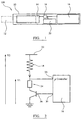
- FIG 1 the components of an embodiment of an electrically heated aerosol generating device 100 are shown in a simplified manner. Particularly, the elements of the electrically heated aerosol generating device 100 are not drawn to scale in Figure 1 . Elements that are not relevant for the understanding of this embodiment have been omitted to simplify Figure 1 .
- the electrically heated aerosol generating device 100 comprises a housing 10 and an aerosol-forming substrate 12, for example a cigarette.
- the aerosol-forming substrate 12 is pushed inside the housing 10 to come into thermal proximity with the heating element 14.
- the aerosol-forming substrate 12 will release a range of volatile compounds at different temperatures. By controlling the maximum operation temperature of the electrically heated aerosol generating device 100 to be below the release temperature of some of the volatile compounds, the release or formation of these smoke constituents can be avoided.
- an electrical energy supply 16 for example a rechargeable lithium ion battery.
- a controller 18 is connected to the heating element 14, the electrical energy supply 16, and a user interface 20, for example a button or display.
- the controller 18 controls the power supplied to the heating element 14 in order to regulate its temperature.
- the aerosol-forming substrate is heated to a temperature of between 250 and 450 degrees centigrade.
- FIG. 2 illustrates control circuitry used to provide the described temperature regulation in accordance with one embodiment of the invention.
- the heater 14 is connected to the battery through connection 22.
- the battery 16 provides a voltage V 2.
- an additional resistor 24, with known resistance r is inserted and connected to voltage V1, intermediate between ground and voltage V2.
- the frequency modulation of the current is controlled by the microcontroller 18 and delivered via its analog output 30 to the transistor 26 which acts as a simple switch.
- the regulation is based on a PID regulator that is part of the software integrated in the microcontroller 18.
- the temperature (or an indication of the temperature) of the heating element is determined by measuring the electrical resistance of the heating element.
- the temperature is used to adjust the duty cycle, in this case the frequency modulation, of the pulses of current supplied to the heating element in order to maintain the heating element at a target temperature.
- the temperature is determined at a frequency chosen to match the control of the duty cycle, and may be determined as often as once every 100ms.
- the analog input 28 on the microcontroller 18 is used to collect the voltage across the resistance 24 and provides the image of the electrical current flowing in the heating element.
- the battery voltage V+ and the voltage across resistor 24 are used to calculate the heating element resistance variation and or its temperature.
- the heater resistance to be measured at a particular temperature is R heater .
- R heater The heater resistance to be measured at a particular temperature.
- the additional resistor 24, whose resistance r is known, is used to determine the current I, again using (1) above.
- the current through the resistor 24 is I and the voltage across the resistor 24 is V1.
- I V 1 r
- the microprocessor 18 can measure V2 and V 1, as the aerosol generating system is being used and, knowing the value of r, can determine the heater's resistance at a particular temperature, R heater .
- the heater resistance is correlated to temperature.
- a relation can be derived based on a combination of two or more linear approximations, each covering a different temperature range.
- This scheme relies on three or more temperature calibration points at which the resistance of the heater is measured. For temperatures intermediate the calibration points, the resistance values are interpolated from the values at the calibration points. The calibration point temperatures are chosen to cover the expected temperature range of the heater during operation.
- the microcontroller may be programmed to limit the maximum allowed duty cycle.
- the maximum allowed duty cycle may change with time following activation of the heating element.
- Figure 3 illustrates the progress a smoking session using a device of the type shown in Figure 1 .
- the target temperature of the heating element is indicated by line 30, and as can be seen is maintained at 375°C through the smoking session, which lasts for six minutes in total.
- the smoking session is split into phases by the microcontroller, with different maximum duty cycle limits in different phases.
- Duty cycle in this context means the percentage of time that the power is being supplied, with switch 26 closed.
- the duty cycle in a first phase the duty cycle is limited to 95% for 30 seconds. During this period the heating element is being raised to the target temperature.
- the duty cycle is limited to 65%. Less power is required to maintain the temperature of the heating element than is required to heat it up.
- the duty cycle is limited to 60%.
- the duty cycle is limited to 55%, in a fifth phase of 60 seconds the duty cycle is limited 50%, and in a sixth phase of 120 seconds the duty cycle is limited to 45%.
- the maximum permitted power is reduced with time for a given target temperature.
- the maximum permitted power or maximum duty cycle, divided by the target temperature is reduced progressively with time following activationof the heating element during a single smoking session.
- Excessive puffing behaviour may also be determined. Each time a user takes a puff on the device, drawing air past the heating element, the amount of oxygen in contact with the substrate is increased, increasing the chance of combustion at a given temperature. With each puff heating element is cooled. The temperature control loop will compensate for this cooling by raising the duty cycle of the current pulses temporarily. Extended periods at or near to the duty cycle limit may be indicative of excessive puffing and trigger a reduction in the duty cycle limit..
- the duty cycle of the current pulses can be monitored by the microcontroller, and if the duty cycle differs from an expected duty cycle over a sustained period, the microcontroller can take corrective action or can terminate the supply of power to the heating element.
- the maximum duty cycle limit may be set to be an upper limit of an expected duty cycle level for normal user behaviour or set to suit a particular user in accordance with his or her preference. If the actual duty cycle is then at the maximum duty cycle limit for much of the time it is indicative that the system is being cooled more than expected by excessive user puffing. As described above, with excessive puffing there is an increased risk of combustion owing to increased oxygen in contact with the substrate.
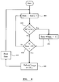
- Figure 4 illustrates a hysteresis control loop, using a Schmitt trigger debounce approach, for detecting such abnormal puffing behaviour and reducing the target temperature or duty cycle limit when such abnormal puffing is detected.
- a Schmitt trigger control loop such as a sliding window control, Infinite Impulse Response (IIR) filters and Finite Impulse Response (FIR) filters.
- step 400 the process of Figure 4 starts and proceeds to step 400, in which an arbitrary state variable "state", which is initially set as 0 is modified by a factor f, which is less than one, say example 0.75.
- step 410 the duty cycle is compared with a duty cycle threshold value DC 1 . If the duty cycle is greater than or equal to the duty cycle threshold value then the state variable is increased by amount c, say 0.25, in step 420 before passing to step 430.
- the duty cycle threshold value DC 1 may be the maximum duty cycle limit of some proportion of the maximum duty cycle limit. If the duty cycle is less that the threshold duty cycle the state variable is unchanged and the process moves to step 430.
- the state variable is then compared with a state threshold ST in step 430.
- the state threshold may be step as 0.8 for example.
- step 400 If the state variable is less than or equal to the state threshold then the process returns to step 400. If the state variable is greater than the state threshold then a pre-burning condition is detected and the either target temperature of the heating element or the maximum duty cycle limit is reduced in step 440. The state variable is then reset in step 450 before the process returns to step 400.
- the process of Figure 4 ensures that very short term fluctuations do not trigger a pre-burning condition detection. Only if the duty cycle exceeds the threshold duty cycle for several cycles of the control process will the pre-burning condition be detected.
- the control loop of Figure 4 is repeated periodically, for example every 100ms, corresponding to the frequency of the PID regulator control loop.
- Figure 5 illustrates a reduction in the target temperature resulting from a control process as illustrated in Figure 4 .
- the upper line 50 indicates the temperature of the heating element.
- the lower line 55 is the duty cycle of the current signal.
- Figure 5 shows that at around 275 seconds after the start of the smoking session, the pre-burning detection mechanism triggered because, starting at around 240 seconds, a lower duty cycle limit caused the temperature to drop more during puffs and the system compensated by keeping the duty cycle at its upper limit for a longer time.
- the target temperature was then reduced to 350°C.
- Figure 6 illustrates a hysteresis control loop, again using a Schmitt trigger debounce approach, for detecting combustion of the substrate.
- an arbitrary state variable "state”, which is initially set as 0, is modified by a factor f, which is less than one, say example 0.9.
- the duty cycle is compared to a second duty cycle threshold DC 2 .
- the second duty cycle threshold is set at 75% of the maximum duty cycle threshold. If the duty cycle is less that the second duty cycle threshold the state variable is incremented by b, in this example 0.3, in step 620, before proceeding to step 630. If the duty cycle is greater than or equal to the second duty cycle threshold, then the state variable is unchanged and the process proceeds directly to step 630.
- step 630 the state variable is compared with a state variable threshold ST, which is equal to one in this example. If the state variable is greater than ST then the power supply is cut to the heating element. The microprocessor simply holds switch 26 open. The process then ends. If the state variable is less than or equal to ST the process returns to step 600.
- ST state variable threshold
- Figure 7 illustrates a burning detection using a process of the type shown in Figure 6 .
- Figure 7 shows a significant drop in duty cycle at around 140 seconds, but this was not sufficient to trigger the burning detection mechanism. However, at around 155 seconds, the duty cycle dropped below the burning detection filter minimum limit and stayed low for some time while the temperature remained at or above a predetermined target. The comparison of actual temperature with the predetermined target may incorporated into the control loop of Figure 6 or may be implemented as a separate process.This triggered the immediate stop of power to the heating element. In effect, the burning detection mechanism detected energy starting to come from the substrate rather than from its electrical source and stopped the smoking experience before the substrate entered auto-combustion.
- FIG. 8 illustrates an example of a control loop for cutting power based on detection of excessive temperature.
- the control loop of Figure 8 may be incorporated into the control loop of Figure 4 or Figure 6 .
- step 800 of Figure 8 may be performed immediately prior to step 400 in each loop.
- the control loop of Figure 8 may be implemented as a separate control loop.
- the actual detected temperature T actual (as determined by the resistance of the heating element or by a separate temperature sensor) is compared with the target temperature T target .
- step 810 power to the heating element is cut.
- Power to the heating element may be cut by the microcontroller controlling a switch, such as switch 26 in Figure 2 .
- the device may then be prevented from operating for a predetermined period of time, during which the heating element cools to an acceptable temperature.
- the use of a simple temperature threshold for cutting power to the heating element provides a direct way to prevent or reduce the likelihood of combustion of the substrate.
Landscapes
- Physics & Mathematics (AREA)
- General Physics & Mathematics (AREA)
- Engineering & Computer Science (AREA)
- Automation & Control Theory (AREA)
- Control Of Resistance Heating (AREA)
- Control Of Temperature (AREA)
- Central Heating Systems (AREA)
Claims (18)
- Verfahren zum Regeln eines elektrischen Heizelements (14); aufweisend:Aufrechterhalten der Temperatur des Heizelements (14) auf einer Zieltemperatur durch Bereitstellen von elektrischen Stromimpulsen an das Heizelement;Überwachen der relativen Einschaltdauer der elektrischen Stromimpulse; undBestimmen, ob sich die relative Einschaltdauer von einer erwarteten relativen Einschaltdauer oder einem Bereich von relativen Einschaltdauern unterscheidet, und die Zieltemperatur zu reduzieren oder das Bereitstellen von Strom an das Heizelement zu stoppen oder die relative Einschaltdauer der an das Heizelement bereitgestellten elektrischen Stromimpulse zu reduzieren, wenn dies der Fall ist.
- Verfahren nach Anspruch 1, wobei das Heizelement (14) ein elektrisches Widerstandsheizelement ist und der Schritt des Aufrechterhaltens der Temperatur des Heizelements auf der Zieltemperatur das Bestimmen des elektrischen Widerstandes des Heizelements und das Anpassen des elektrischen Stroms aufweist, der an das Heizelement bereitgestellt wird, abhängig von dem bestimmten elektrischen Widerstand.
- Verfahren nach einem der vorstehenden Ansprüche, wobei der Schritt des Bestimmens, ob sich die relative Einschaltdauer von einer erwarteten relativen Einschaltdauer unterscheidet, das periodische Vergleichen der relativen Einschaltdauer mit einer ersten Schwelleneinschaltdauer und das Verwenden einer Hystereseregelschleife aufweist, um einen Auslösepunkt zu bestimmen, an dem die Zieltemperatur reduziert oder die relative Einschaltdauer der elektrischen Stromimpulse begrenzt wird.
- Verfahren nach einem vorstehenden Anspruch, aufweisend das Unterbrechen des Bereitstellens von elektrischem Strom an das Heizelement, wenn die relative Einschaltdauer kleiner als eine zweite Schwelleneinschaltdauer ist, während sich die Temperatur über der Zieltemperatur befindet.
- Verfahren nach Anspruch 3 oder 4, aufweisend das Begrenzen der relativen Einschaltdauer der elektrischen Stromimpulse auf eine maximale Einschaltdauergrenze, wobei der erste oder zweite Schwellenwert oder sowohl der erste als auch der zweite Schwellenwert proportional zu der maximalen Einschaltdauergrenze sind.
- Verfahren nach Anspruch 5, wobei eine Variable A stufenweise mit zunehmender Zeit nach der Aktivierung des Heizelements reduziert wird, wobei A gleich der maximalen relativen Einschaltdauer geteilt durch die Zieltemperatur ist.
- Vorrichtung zum Regeln eines elektrischen Heizelements (14), aufweisend:einen Steuerkreis (18), der mit dem Heizelement (14) verbunden und ausgelegt ist, die Temperatur des Heizelements durch Bereitstellen von elektrischen Stromimpulsen an das Heizelement auf einer Zieltemperatur aufrechtzuerhalten; undeine Auswerteschaltung, die ausgelegt ist, die relative Einschaltdauer der elektrischen Stromimpulse zu überwachen und den Steuerkreis anzuweisen, die Zieltemperatur zu reduzieren oder das Bereitstellen von Strom an das Heizelement zu stoppen oder die relative Einschaltdauer oder die elektrischen Stromimpulse zu begrenzen, wenn sich die relative Einschaltdauer der elektrischen Stromimpulse von einer erwarteten relativen Einschaltdauer oder einem Bereich von relativen Einschaltdauern unterscheidet.
- Vorrichtung nach Anspruch 7, wobei das Heizelement (14) ein elektrisches Widerstandsheizelement ist und der Steuerkreis ausgelegt ist, die Temperatur des Heizelements auf der Zieltemperatur aufrechtzuerhalten durch Bestimmen des elektrischen Widerstands des Heizelements und Anpassen des elektrischen Stroms, der an das Heizelement bereitgestellt wird, abhängig von dem bestimmten elektrischen Widerstand.
- Vorrichtung nach Anspruch 7 oder 8, wobei die Auswerteschaltung ausgelegt ist, die relative Einschaltdauer mit einer ersten Schwelleneinschaltdauer periodisch zu vergleichen, und eine Hystereseregelschleife aufweist, die ausgelegt ist, einen Auslösepunkt zu bestimmen, an dem die Zieltemperatur reduziert oder die relative Einschaltdauer der elektrischen Stromimpulse begrenzt wird.
- Vorrichtung nach einem der Ansprüche 7 bis 9, wobei die Auswerteschaltung derart ausgelegt ist, dass die Auswerteschaltung den Steuerkreis anweist, das Bereitstellen von elektrischem Strom an das Heizelement zu unterbrechen, wenn die relative Einschaltdauer kleiner als eine zweite Schwelleneinschaltdauer ist, während sich die Temperatur bei oder über der Zieltemperatur befindet.
- Vorrichtung nach einem der Ansprüche 7 bis 10, wobei der Steuerkreis ausgelegt ist, die relative Einschaltdauer der elektrischen Stromimpulse auf eine maximale Einschaltdauergrenze zu begrenzen, sodass eine Variable A stufenweise mit zunehmender Zeit nach der Aktivierung des Heizelements reduziert wird, wobei A gleich der maximalen relativen Einschaltdauer geteilt durch die Zieltemperatur ist.
- Vorrichtung nach einem der Ansprüche 7 bis 11, wobei der Steuerkreis ausgelegt ist, das Bereitstellen von elektrischem Strom an das Heizelement zu unterbrechen, wenn die Temperatur des Heizelements eine Temperaturschwelle überschreitet.
- Vorrichtung nach einem der Ansprüche 7 bis 12, wobei die Vorrichtung eine Aerosolerzeugungsvorrichtung ist, die ein Heizelement wie eine elektrisch heizende Vorrichtung zum Rauchen aufweist.
- Vorrichtung nach Anspruch 13, wobei die Aerosolerzeugungsvorrichtung ausgelegt ist, ein aerosolbildendes Substrat aufzunehmen, und wobei die erwartete relative Einschaltdauer oder der Bereich von relativen Einschaltdauern abhängig von einer Charakteristik des aerosolbildenden Substrats konfigurierbar ist.
- Aerosolerzeugungssystem, aufweisend:eine Aerosolerzeugungsvorrichtung (100), die ein Heizelement (14) aufweist, und einen aerosolerzeugenden Artikel, der ein aerosolbildendes Substrat (12) aufweist, wobei die Heizvorrichtung ausgelegt ist, das aerosolbildende Substrat zu erwärmen, um ein Aerosol zu erzeugen, und wobei die Aerosolerzeugungsvorrichtung aufweist: einen Steuerkreis (18), der mit dem Heizelement verbunden und ausgelegt ist, die Temperatur des Heizelements durch Bereitstellen von elektrischen Stromimpulsen an das Heizelement auf einer Zieltemperatur aufrechtzuerhalten;eine Auswerteschaltung, die ausgelegt ist, die relative Einschaltdauer der elektrischen Stromimpulse zu überwachen und, wenn sich die relative Einschaltdauer der elektrischen Stromimpulse von einer erwarteten relativen Einschaltdauer oder einem Bereich von relativen Einschaltdauern unterscheidet, den Steuerkreis anzuweisen, die Zieltemperatur zu reduzieren oder das Bereitstellen von Strom an das Heizelement zu stoppen oder die relative Einschaltdauer oder die elektrischen Stromimpulse zu begrenzen.
- System nach Anspruch 15, wobei die Aerosolerzeugungsvorrichtung derart ausgelegt ist, dass die erwartete relative Einschaltdauer oder der Bereich von relativen Einschaltdauern von einer Charakteristik des aerosolbildenden Substrats abhängig ist.
- Computerprogramm, das bei Ausführung auf programmierbaren elektrischen Schaltungen für eine elektrisch betriebene Aerosolerzeugungsvorrichtung die programmierbaren elektrischen Schaltungen veranlasst, ein Verfahren nach einem der Ansprüche 1 bis 6 auszuführen.
- Computerlesbares Speichermedium, auf dem ein Computerprogramm nach Anspruch 17 gespeichert ist.
Priority Applications (5)
| Application Number | Priority Date | Filing Date | Title |
|---|---|---|---|
| PL13774365T PL2895930T3 (pl) | 2012-09-11 | 2013-09-10 | Urządzenie i sposób sterowania elektrycznym ogrzewaczem w celu sterowania temperaturą |
| RS20161029A RS55379B1 (sr) | 2012-09-11 | 2013-09-10 | Uređaj i postupak za kontrolisanje električnog grejača da bi se kontrolisala temperatura |
| DK15193539.2T DK3002657T3 (en) | 2012-09-11 | 2013-09-10 | Device and method for controlling an electric heater to limit temperature |
| EP13774365.4A EP2895930B1 (de) | 2012-09-11 | 2013-09-10 | Vorrichtung und verfahren zum steuern einer elektroheizung zur regelung der temperatur |
| EP15193539.2A EP3002657B1 (de) | 2012-09-11 | 2013-09-10 | Vorrichtung und verfahren zur steuerung einer elektroheizung zur einschränkung der temperatur |
Applications Claiming Priority (3)
| Application Number | Priority Date | Filing Date | Title |
|---|---|---|---|
| EP12183837 | 2012-09-11 | ||
| PCT/EP2013/068722 WO2014040988A2 (en) | 2012-09-11 | 2013-09-10 | Device and method for controlling an electrical heater to limit temperature |
| EP13774365.4A EP2895930B1 (de) | 2012-09-11 | 2013-09-10 | Vorrichtung und verfahren zum steuern einer elektroheizung zur regelung der temperatur |
Related Child Applications (2)
| Application Number | Title | Priority Date | Filing Date |
|---|---|---|---|
| EP15193539.2A Division EP3002657B1 (de) | 2012-09-11 | 2013-09-10 | Vorrichtung und verfahren zur steuerung einer elektroheizung zur einschränkung der temperatur |
| EP15193539.2A Division-Into EP3002657B1 (de) | 2012-09-11 | 2013-09-10 | Vorrichtung und verfahren zur steuerung einer elektroheizung zur einschränkung der temperatur |
Publications (2)
| Publication Number | Publication Date |
|---|---|
| EP2895930A2 EP2895930A2 (de) | 2015-07-22 |
| EP2895930B1 true EP2895930B1 (de) | 2016-11-02 |
Family
ID=46888926
Family Applications (2)
| Application Number | Title | Priority Date | Filing Date |
|---|---|---|---|
| EP13774365.4A Active EP2895930B1 (de) | 2012-09-11 | 2013-09-10 | Vorrichtung und verfahren zum steuern einer elektroheizung zur regelung der temperatur |
| EP15193539.2A Active EP3002657B1 (de) | 2012-09-11 | 2013-09-10 | Vorrichtung und verfahren zur steuerung einer elektroheizung zur einschränkung der temperatur |
Family Applications After (1)
| Application Number | Title | Priority Date | Filing Date |
|---|---|---|---|
| EP15193539.2A Active EP3002657B1 (de) | 2012-09-11 | 2013-09-10 | Vorrichtung und verfahren zur steuerung einer elektroheizung zur einschränkung der temperatur |
Country Status (30)
| Country | Link |
|---|---|
| US (2) | US9713345B2 (de) |
| EP (2) | EP2895930B1 (de) |
| JP (2) | JP5971829B2 (de) |
| KR (2) | KR101619034B1 (de) |
| CN (2) | CN105027016B (de) |
| AR (1) | AR092531A1 (de) |
| AU (1) | AU2013314436B2 (de) |
| BR (1) | BR112015004669B1 (de) |
| CA (1) | CA2880481A1 (de) |
| DK (2) | DK3002657T3 (de) |
| ES (2) | ES2621163T3 (de) |
| HK (2) | HK1208920A1 (de) |
| HU (2) | HUE031223T2 (de) |
| IL (1) | IL237099B (de) |
| IN (1) | IN2015DN00754A (de) |
| LT (2) | LT2895930T (de) |
| MX (1) | MX354893B (de) |
| MY (1) | MY169408A (de) |
| NZ (1) | NZ705806A (de) |
| PH (1) | PH12015500131B1 (de) |
| PL (2) | PL2895930T3 (de) |
| PT (2) | PT2895930T (de) |
| RS (2) | RS55847B1 (de) |
| RU (2) | RU2619372C2 (de) |
| SG (1) | SG11201501700SA (de) |
| SI (1) | SI3002657T1 (de) |
| TW (1) | TWI595340B (de) |
| UA (1) | UA118439C2 (de) |
| WO (1) | WO2014040988A2 (de) |
| ZA (1) | ZA201500400B (de) |
Cited By (2)
| Publication number | Priority date | Publication date | Assignee | Title |
|---|---|---|---|---|
| US11528943B2 (en) | 2017-10-24 | 2022-12-20 | Japan Tobacco Inc. | Aerosol generating apparatus and method and program for actuating the same |
| US11789476B2 (en) | 2021-01-18 | 2023-10-17 | Altria Client Services Llc | Heat-not-burn (HNB) aerosol-generating devices including intra-draw heater control, and methods of controlling a heater |
Families Citing this family (192)
| Publication number | Priority date | Publication date | Assignee | Title |
|---|---|---|---|---|
| US20160345631A1 (en) | 2005-07-19 | 2016-12-01 | James Monsees | Portable devices for generating an inhalable vapor |
| EP2100525A1 (de) * | 2008-03-14 | 2009-09-16 | Philip Morris Products S.A. | Elektrisch beheiztes Aerosolerzeugungssystem und Verfahren |
| US10517530B2 (en) | 2012-08-28 | 2019-12-31 | Juul Labs, Inc. | Methods and devices for delivering and monitoring of tobacco, nicotine, or other substances |
| US10034988B2 (en) | 2012-11-28 | 2018-07-31 | Fontem Holdings I B.V. | Methods and devices for compound delivery |
| TWI608805B (zh) * | 2012-12-28 | 2017-12-21 | 菲利浦莫里斯製品股份有限公司 | 加熱型氣溶膠產生裝置及用於產生具有一致性質的氣溶膠之方法 |
| US10653180B2 (en) | 2013-06-14 | 2020-05-19 | Juul Labs, Inc. | Multiple heating elements with separate vaporizable materials in an electric vaporization device |
| US10279934B2 (en) | 2013-03-15 | 2019-05-07 | Juul Labs, Inc. | Fillable vaporizer cartridge and method of filling |
| KR20230013165A (ko) | 2013-05-06 | 2023-01-26 | 쥴 랩스, 인크. | 에어로졸 장치를 위한 니코틴 염 제제 및 그 방법 |
| US10194693B2 (en) | 2013-09-20 | 2019-02-05 | Fontem Holdings 1 B.V. | Aerosol generating device |
| US10980273B2 (en) | 2013-11-12 | 2021-04-20 | VMR Products, LLC | Vaporizer, charger and methods of use |
| CA2932464C (en) | 2013-12-05 | 2023-01-03 | Pax Labs, Inc. | Nicotine liquid formulations for aerosol devices and methods thereof |
| US20160366947A1 (en) | 2013-12-23 | 2016-12-22 | James Monsees | Vaporizer apparatus |
| US10076139B2 (en) | 2013-12-23 | 2018-09-18 | Juul Labs, Inc. | Vaporizer apparatus |
| FI3491948T4 (fi) | 2013-12-23 | 2024-05-06 | Juul Labs International Inc | Höyrystyslaitejärjestelmiä |
| USD825102S1 (en) | 2016-07-28 | 2018-08-07 | Juul Labs, Inc. | Vaporizer device with cartridge |
| US10159282B2 (en) | 2013-12-23 | 2018-12-25 | Juul Labs, Inc. | Cartridge for use with a vaporizer device |
| USD842536S1 (en) | 2016-07-28 | 2019-03-05 | Juul Labs, Inc. | Vaporizer cartridge |
| US10058129B2 (en) | 2013-12-23 | 2018-08-28 | Juul Labs, Inc. | Vaporization device systems and methods |
| TWI684414B (zh) | 2014-02-06 | 2020-02-11 | 美商尤爾實驗室有限公司 | 汽化裝置系統及方法 |
| US10709173B2 (en) | 2014-02-06 | 2020-07-14 | Juul Labs, Inc. | Vaporizer apparatus |
| GB201413018D0 (en) | 2014-02-28 | 2014-09-03 | Beyond Twenty Ltd | Beyond 1A |
| US11085550B2 (en) | 2014-02-28 | 2021-08-10 | Ayr Ltd. | Electronic vaporiser system |
| US10130119B2 (en) | 2014-02-28 | 2018-11-20 | Beyond Twenty Ltd. | Electronic vaporiser system |
| US10136674B2 (en) | 2014-02-28 | 2018-11-27 | Beyond Twenty Ltd. | Electronic vaporiser system |
| US10588176B2 (en) | 2014-02-28 | 2020-03-10 | Ayr Ltd. | Electronic vaporiser system |
| US10287154B2 (en) | 2014-02-28 | 2019-05-14 | Ayr Ltd. | Electronic vaporiser system |
| US10091839B2 (en) | 2014-02-28 | 2018-10-02 | Beyond Twenty Ltd. | Electronic vaporiser system |
| TWI681691B (zh) * | 2014-04-30 | 2020-01-01 | 瑞士商菲利浦莫里斯製品股份有限公司 | 電熱式氣溶膠產生系統、裝置及其控制方法 |
| US11478021B2 (en) | 2014-05-16 | 2022-10-25 | Juul Labs, Inc. | Systems and methods for aerosolizing a vaporizable material |
| PL3363306T3 (pl) | 2014-05-21 | 2021-01-25 | Philip Morris Products S.A. | Układ wytwarzania aerozolu z grzaniem elektrycznym wraz z powlekanym elementem grzejnym |
| MY175716A (en) * | 2014-05-21 | 2020-07-07 | Philip Morris Products Sa | Aerosol-generating article with multi-material susceptor |
| CA2940927C (en) | 2014-05-21 | 2023-08-01 | Philip Morris Products S.A. | Aerosol-generating article with internal susceptor |
| CN204146320U (zh) * | 2014-06-06 | 2015-02-11 | 黄金珍 | 电子烟雾化器 |
| CN106455718B (zh) | 2014-06-14 | 2022-07-15 | 进化有限公司 | 具有温度感测和限值的电子汽化器 |
| GB2527349A (en) * | 2014-06-19 | 2015-12-23 | Ciaran Oglesby | Improved vaporizer and vaporizing method |
| CA160775S (en) | 2014-08-11 | 2015-09-29 | Ploom Inc | Electronic vaporization device with cartridge |
| CN111449299B (zh) | 2014-08-22 | 2024-02-13 | 富特姆投资有限公司 | 用于控制加热元件的方法、系统和装置 |
| TWI680726B (zh) * | 2014-10-13 | 2020-01-01 | 瑞士商菲利浦莫里斯製品股份有限公司 | 控制電熱式吸煙系統中之電加熱器的方法及電熱式吸煙系統 |
| EP3821735A1 (de) | 2014-12-05 | 2021-05-19 | Juul Labs, Inc. | Kalibrierte dosissteuerung |
| CN104571190B (zh) * | 2015-01-22 | 2017-05-10 | 卓尔悦欧洲控股有限公司 | 温控系统及其电子烟 |
| ES2864663T3 (es) * | 2015-03-26 | 2021-10-14 | Philip Morris Products Sa | Gestión de calentadores |
| EP3282871B2 (de) | 2015-04-15 | 2024-03-20 | Philip Morris Products S.A. | Vorrichtung und verfahren zur steuerung einer elektroheizung zur einschränkung der temperatur entsprechend eines gewünschten temperaturprofils mit der zeit |
| KR102626544B1 (ko) * | 2015-05-26 | 2024-01-18 | 필립모리스 프로덕츠 에스.에이. | 에어로졸 발생 시스템 제어 |
| US10736356B2 (en) | 2015-06-25 | 2020-08-11 | Altria Client Services Llc | Electronic vaping device having pressure sensor |
| TW201707587A (zh) * | 2015-08-21 | 2017-03-01 | 力智電子股份有限公司 | 電子菸的功率控制電路與功率控制方法 |
| GB201515087D0 (en) | 2015-08-25 | 2015-10-07 | Nicoventures Holdings Ltd | Electronic vapour provision system |
| GB2541719B (en) | 2015-08-27 | 2019-06-12 | Nerudia Ltd | An inhaler |
| GB2543905B (en) * | 2015-09-01 | 2020-04-29 | Ayr Ltd | Electronic vaporiser system |
| WO2017037457A1 (en) | 2015-09-01 | 2017-03-09 | Beyond Twenty Limited | Electronic vaporiser system |
| JP6847926B2 (ja) | 2015-09-16 | 2021-03-24 | フィリップ・モーリス・プロダクツ・ソシエテ・アノニム | 可撓性の壁を有する液体貯蔵部分を有するカートリッジ |
| US11602019B2 (en) | 2015-09-16 | 2023-03-07 | Altria Client Services Llc | Cartridge with a capacity sensor |
| CN105163406A (zh) * | 2015-10-12 | 2015-12-16 | 珠海格力电器股份有限公司 | 一种电加热器的控制方法及系统 |
| US10165799B2 (en) | 2015-11-17 | 2019-01-01 | Altria Client Services Llc | Aerosol-generating system with self-activated electric heater |
| CN106820265B (zh) * | 2015-12-07 | 2021-07-09 | 深圳麦克韦尔科技有限公司 | 电子烟及其加热雾化控制方法 |
| US11064741B2 (en) | 2016-02-09 | 2021-07-20 | Altria Client Services Llc | Element for an electrically operated aerosol-generating system having a dual function |
| JP6826608B2 (ja) * | 2016-02-09 | 2021-02-03 | フィリップ・モーリス・プロダクツ・ソシエテ・アノニム | 二重の機能を有する電気的に作動するエアロゾル発生システム用の構成要素 |
| EP3413960B1 (de) | 2016-02-11 | 2021-03-31 | Juul Labs, Inc. | Füllbare verdampferkartusche und verfahren zum füllen |
| SG11201806801VA (en) | 2016-02-11 | 2018-09-27 | Juul Labs Inc | Securely attaching cartridges for vaporizer devices |
| JP6850299B2 (ja) * | 2016-02-19 | 2021-03-31 | フィリップ・モーリス・プロダクツ・ソシエテ・アノニム | 使用法判定を備えるエアロゾル発生システム |
| CA3009109A1 (en) | 2016-02-25 | 2017-08-31 | Philip Morris Products S.A. | Electrically operated aerosol-generating system with tilt sensor |
| US10932495B2 (en) | 2016-02-25 | 2021-03-02 | Altria Client Services Llc | Electrically operated aerosol-generating system with temperature sensor |
| US10912333B2 (en) | 2016-02-25 | 2021-02-09 | Juul Labs, Inc. | Vaporization device control systems and methods |
| US11006669B2 (en) | 2016-02-25 | 2021-05-18 | Altria Client Services Llc | Aerosol-generating systems with liquid level determination and methods of determining liquid level in aerosol-generating systems |
| US10405582B2 (en) | 2016-03-10 | 2019-09-10 | Pax Labs, Inc. | Vaporization device with lip sensing |
| KR101682349B1 (ko) * | 2016-04-08 | 2017-01-09 | 사단법인 캠틱종합기술원 | 탄소섬유 발열선의 온도제어방법 |
| CN105867459B (zh) * | 2016-04-19 | 2018-11-23 | 武汉理工大学 | 一种碳纤维电热温控器 |
| USD849996S1 (en) | 2016-06-16 | 2019-05-28 | Pax Labs, Inc. | Vaporizer cartridge |
| USD836541S1 (en) | 2016-06-23 | 2018-12-25 | Pax Labs, Inc. | Charging device |
| USD848057S1 (en) | 2016-06-23 | 2019-05-07 | Pax Labs, Inc. | Lid for a vaporizer |
| USD851830S1 (en) | 2016-06-23 | 2019-06-18 | Pax Labs, Inc. | Combined vaporizer tamp and pick tool |
| FR3053784B1 (fr) | 2016-07-07 | 2020-01-17 | Airbus Defence And Space Sas | Procedes de determination et de regulation de la temperature d’un propulseur electrique |
| KR102523292B1 (ko) * | 2016-07-14 | 2023-04-20 | 필립모리스 프로덕츠 에스.에이. | 에어로졸 발생 시스템용 유체 투과성 히터 조립체 및 카토마이저 카트리지 |
| US11147315B2 (en) * | 2016-07-25 | 2021-10-19 | Fontem Holdings 1 B.V. | Controlling an operation of an electronic cigarette |
| AR109120A1 (es) | 2016-07-26 | 2018-10-31 | British American Tobacco Investments Ltd | Aparato para calentar material fumable |
| WO2018027189A2 (en) * | 2016-08-05 | 2018-02-08 | Juul Labs, Inc. | Anemometric-assisted control of a vaporizer |
| WO2018045544A1 (zh) | 2016-09-09 | 2018-03-15 | 绿仕科技控股有限公司 | 环境参数测量系统 |
| AU2017328499A1 (en) | 2016-09-14 | 2019-04-04 | Altria Client Services Llc | Smoking device |
| US11660403B2 (en) | 2016-09-22 | 2023-05-30 | Juul Labs, Inc. | Leak-resistant vaporizer device |
| GB201616430D0 (en) | 2016-09-28 | 2016-11-09 | Nicoventures Holdings Limited | Liquid storage tank for a vapour provision system |
| US10764963B2 (en) | 2016-10-07 | 2020-09-01 | S. C. Johnson & Son, Inc. | Volatile material dispenser |
| US10448458B2 (en) * | 2016-10-21 | 2019-10-15 | Watlow Electric Manufacturing Company | Electric heaters with low drift resistance feedback |
| TW201818833A (zh) * | 2016-11-22 | 2018-06-01 | 瑞士商菲利浦莫里斯製品股份有限公司 | 感應加熱裝置、包含感應加熱裝置之氣溶膠產生系統及其操作方法 |
| JP7167028B2 (ja) | 2016-12-27 | 2022-11-08 | ジュール・ラブズ・インコーポレイテッド | 電子式ヴェポライザー用熱伝導芯 |
| GB201701102D0 (en) | 2017-01-23 | 2017-03-08 | Nicoventures Holdings Ltd | Electronic vapour provision system |
| CN110381758B (zh) * | 2017-03-14 | 2022-06-17 | 菲利普莫里斯生产公司 | 用于电池供电的气溶胶生成装置的功率管理方法和系统 |
| EA201991563A1 (ru) * | 2017-04-24 | 2019-11-29 | Генерирующее аэрозоль устройство, способ управления генерирующим аэрозоль устройством и программа | |
| KR102183093B1 (ko) * | 2017-05-11 | 2020-11-25 | 주식회사 케이티앤지 | 온도를 가변적으로 제어할 수 있는 방법 및 장치 |
| PT3622838T (pt) | 2017-05-11 | 2024-04-30 | Kt&G Corp | Vaporizador e dispositivo de geração de aerossol incluindo o mesmo |
| KR20180124739A (ko) | 2017-05-11 | 2018-11-21 | 주식회사 케이티앤지 | 궐련의 종류별로 에어로졸 생성장치에 포함된 히터의 온도를 제어하는 방법 및 궐련의 종류별로 히터의 온도를 제어하는 에어로졸 생성장치 |
| JP7112427B2 (ja) * | 2017-06-28 | 2022-08-03 | フィリップ・モーリス・プロダクツ・ソシエテ・アノニム | エアロゾル形成基体を抵抗加熱するための電気加熱組立品、エアロゾル発生装置および方法 |
| EP3646668B1 (de) | 2017-06-28 | 2022-03-09 | Philip Morris Products S.A. | Anordnung zur elektrischen erwärmung, aerosolerzeugungsvorrichtung und verfahren zur resistiven erwärmung eines aerosolerzeugenden substrats |
| WO2019002613A1 (en) * | 2017-06-30 | 2019-01-03 | Philip Morris Products S.A. | INDUCTION HEATING DEVICE, AEROSOL GENERATING SYSTEM COMPRISING AN INDUCTION HEATING DEVICE, AND METHOD OF USE |
| WO2019030363A1 (en) * | 2017-08-09 | 2019-02-14 | Philip Morris Products S.A. | AEROSOL GENERATION DEVICE WITH FLAT INDUCTION COIL |
| KR20190049391A (ko) | 2017-10-30 | 2019-05-09 | 주식회사 케이티앤지 | 히터를 구비한 에어로졸 생성 장치 |
| GB201713681D0 (en) | 2017-08-25 | 2017-10-11 | Nicoventures Holdings Ltd | Vapour provision systems |
| USD887632S1 (en) | 2017-09-14 | 2020-06-16 | Pax Labs, Inc. | Vaporizer cartridge |
| WO2019066245A1 (ko) * | 2017-09-26 | 2019-04-04 | 주식회사 케이티앤지 | 에어로졸 생성장치의 피드백 제어기능을 구현하는 방법 및 그 에어로졸 생성장치 |
| KR102105548B1 (ko) | 2017-09-26 | 2020-04-28 | 주식회사 케이티앤지 | 에어로졸 생성장치의 피드백 제어기능을 구현하는 방법 및 그 에어로졸 생성장치 |
| CN107510096A (zh) * | 2017-09-27 | 2017-12-26 | 深圳市舜宝科技有限公司 | 一种电子烟发热片的温控系统 |
| CN111093409B (zh) * | 2017-10-05 | 2024-02-09 | 菲利普莫里斯生产公司 | 具有连续功率调节的电操作气溶胶生成装置 |
| EA202090952A1 (ru) | 2017-10-24 | 2020-10-23 | Джапан Тобакко Инк. | Аэрозоль-генерирующее устройство |
| KR102443306B1 (ko) | 2017-10-24 | 2022-09-14 | 니뽄 다바코 산교 가부시키가이샤 | 에어로졸 생성 장치 및 이를 동작시키는 방법 및 프로그램 |
| KR102322385B1 (ko) | 2017-10-24 | 2021-11-04 | 니뽄 다바코 산교 가부시키가이샤 | 에어로졸 생성 장치, 에어로졸 생성 장치의 제어 방법, 에어로졸원 또는 향미원의 잔량 추정 방법, 및 이 방법들을 프로세서에 실행시키기 위한 프로그램 |
| EP4014767A3 (de) | 2017-10-24 | 2022-08-31 | Japan Tobacco Inc. | Aerosolerzeugungsgerät, verfahren zur steuerung eines aerosolerzeugungsgerätes und programm zur veranlassung eines prozessors zur ausführung des verfahrens |
| EP3701813B1 (de) | 2017-10-24 | 2022-01-12 | Japan Tobacco Inc. | Aerosolgenerator sowie verfahren und programm zur betätigung desselben |
| WO2019088559A2 (ko) | 2017-10-30 | 2019-05-09 | 주식회사 케이티앤지 | 에어로졸 생성 장치 |
| WO2019088580A2 (ko) | 2017-10-30 | 2019-05-09 | 주식회사 케이티앤지 | 에어로졸 생성 장치 |
| EP3704972A4 (de) | 2017-10-30 | 2021-09-15 | KT&G Corporation | Aerosolerzeugungsvorrichtung und heizer für aerosolerzeugungsvorrichtung |
| RU2738546C2 (ru) | 2017-10-30 | 2020-12-14 | Кейтиэндджи Корпорейшн | Устройство для генерирования аэрозоля и способ управления таким устройством |
| KR102138245B1 (ko) | 2017-10-30 | 2020-07-28 | 주식회사 케이티앤지 | 에어로졸 생성 장치 |
| KR102057215B1 (ko) | 2017-10-30 | 2019-12-18 | 주식회사 케이티앤지 | 에어로졸 생성 장치 및 생성 방법 |
| KR102180421B1 (ko) | 2017-10-30 | 2020-11-18 | 주식회사 케이티앤지 | 에어로졸 생성 장치 |
| KR102138246B1 (ko) | 2017-10-30 | 2020-07-28 | 주식회사 케이티앤지 | 증기화기 및 이를 구비하는 에어로졸 생성 장치 |
| KR102057216B1 (ko) | 2017-10-30 | 2019-12-18 | 주식회사 케이티앤지 | 에어로졸 생성 장치 및 에어로졸 생성 장치용 히터 조립체 |
| US11617395B2 (en) | 2017-11-30 | 2023-04-04 | Philip Morris Products S.A. | Aerosol-generating device and method for controlling a heater of an aerosol-generating device |
| CN107946801A (zh) * | 2017-12-15 | 2018-04-20 | 深圳市舜宝科技有限公司 | 一种电气连接装置 |
| GB201721646D0 (en) * | 2017-12-21 | 2018-02-07 | British American Tobacco Investments Ltd | Aerosol provision device |
| TW201931945A (zh) * | 2017-12-29 | 2019-08-01 | 瑞士商傑太日煙國際股份有限公司 | 用於一蒸氣產生裝置之加熱總成 |
| EP3744195B1 (de) * | 2018-01-26 | 2023-08-02 | Japan Tobacco Inc. | Aerosolerzeugungsvorrichtung |
| KR102554492B1 (ko) * | 2018-02-07 | 2023-07-11 | 르노 에스.아.에스. | 사전에 정의된 온도 임계값을 초과하는 경우를 검출하는 방법 및 장치 |
| WO2019186670A1 (ja) * | 2018-03-26 | 2019-10-03 | 日本たばこ産業株式会社 | エアロゾル生成装置及び制御方法並びにプログラム |
| WO2019186667A1 (ja) | 2018-03-26 | 2019-10-03 | 日本たばこ産業株式会社 | エアロゾル生成装置及び制御方法並びにプログラム |
| RU2756544C1 (ru) | 2018-03-26 | 2021-10-01 | Джапан Тобакко Инк. | Устройство формирования аэрозоля, способ управления и программа |
| WO2019186669A1 (ja) | 2018-03-26 | 2019-10-03 | 日本たばこ産業株式会社 | エアロゾル生成装置及び制御方法並びにプログラム |
| WO2019186666A1 (ja) | 2018-03-26 | 2019-10-03 | 日本たばこ産業株式会社 | エアロゾル生成装置及び制御方法並びにプログラム |
| GB201806245D0 (en) * | 2018-04-17 | 2018-05-30 | Nicoventures Trading Ltd | Delivery vehicle |
| MX2020010915A (es) * | 2018-04-23 | 2020-11-09 | Philip Morris Products Sa | Un dispositivo generador de aerosol que tiene el control basado en la temperatura. |
| WO2019228894A1 (en) * | 2018-05-30 | 2019-12-05 | Philip Morris Products S.A. | Detection of adverse heater conditions in an electrically heated aerosol generating system |
| CN108618207A (zh) * | 2018-05-31 | 2018-10-09 | 绿烟实业(深圳)有限公司 | 控制气雾生成装置中气雾产生的方法和气雾生成装置 |
| CN112469295B (zh) * | 2018-06-22 | 2022-06-14 | 日本烟草产业株式会社 | 气溶胶生成装置以及使其动作的方法以及记录介质 |
| KR102148827B1 (ko) * | 2018-06-26 | 2020-08-27 | 주식회사 이엠텍 | 미세 입자 발생 장치의 예열완료 시간 제어 방법 및 미세 입자 발생 장치 |
| KR102205694B1 (ko) * | 2018-07-04 | 2021-01-21 | 주식회사 이엠텍 | 미세 입자 발생 장치 |
| KR102283057B1 (ko) * | 2018-07-04 | 2021-07-28 | 주식회사 케이티앤지 | 에어로졸 생성장치의 이상동작 예방 방법 및 그 시스템 |
| KR102116118B1 (ko) * | 2018-07-18 | 2020-05-27 | 주식회사 케이티앤지 | 에어로졸 생성장치의 히터의 온도를 구간별로 제어하는 방법 및 그 방법을 구현하기 위한 에어로졸 생성장치 |
| KR102146055B1 (ko) * | 2018-07-19 | 2020-08-19 | 주식회사 케이티앤지 | 에어로졸 생성장치의 히터의 오버슛을 방지하는 방법 및 그 방법을 구현하기 위한 에어로졸 생성장치 |
| JP7390354B2 (ja) * | 2018-07-25 | 2023-12-01 | フィリップ・モーリス・プロダクツ・ソシエテ・アノニム | エアロゾル発生システムにおける加熱を制御する方法 |
| KR102184703B1 (ko) * | 2018-08-01 | 2020-11-30 | 주식회사 케이티앤지 | 히터의 온도를 제어하는 방법 및 그 방법을 수행하는 에어로졸 생성 장치 |
| CN108652089A (zh) | 2018-08-07 | 2018-10-16 | 深圳市合元科技有限公司 | 一种电子烟控制方法及电子烟具 |
| CN208909131U (zh) * | 2018-08-20 | 2019-05-31 | 常州市派腾电子技术服务有限公司 | 控制电路以及电子烟 |
| GB2580213B (en) | 2018-10-15 | 2021-10-27 | Juul Labs Inc | Heating element |
| CA3103713A1 (en) * | 2018-10-19 | 2020-04-23 | Juul Labs, Inc. | Vaporizer power system |
| KR102203851B1 (ko) * | 2018-11-12 | 2021-01-15 | 주식회사 케이티앤지 | 에어로졸 생성 장치 및 이를 제어하는 방법 |
| KR102194731B1 (ko) * | 2018-11-16 | 2020-12-23 | 주식회사 케이티앤지 | 하나의 배터리로 두 개의 히터들에 전력을 공급하는 에어로졸 생성 장치 |
| KR102199794B1 (ko) | 2018-11-16 | 2021-01-07 | 주식회사 케이티앤지 | 연속사용이 가능한 에어로졸 생성장치의 히터의 전력을 제어하는 방법 및 그 에어로졸 생성장치 |
| KR102199795B1 (ko) * | 2018-11-19 | 2021-01-07 | 주식회사 케이티앤지 | 일정주파수 이하의 신호로 에어로졸 생성장치의 히터의 전력을 제어하는 방법 및 그 에어로졸 생성장치 |
| CN109862633B (zh) * | 2018-11-30 | 2022-02-08 | 苏州烯时代材料科技有限公司 | 一种石墨烯电热膜 |
| KR102242309B1 (ko) * | 2018-12-13 | 2021-04-20 | 주식회사 케이티앤지 | 오작동에 의한 히터의 발열을 차단하는 에어로졸 생성 장치 및 방법 |
| KR102385406B1 (ko) * | 2018-12-13 | 2022-04-11 | 주식회사 케이티앤지 | 오작동에 의한 히터의 발열을 차단하는 에어로졸 생성 장치 및 방법 |
| KR102199797B1 (ko) * | 2018-12-14 | 2021-01-07 | 주식회사 케이티앤지 | 에어로졸 생성 장치 및 그 동작 방법 |
| CN111351985B (zh) * | 2018-12-24 | 2022-02-11 | 深圳御烟实业有限公司 | 电阻检测系统和方法 |
| CN109730360A (zh) * | 2019-01-21 | 2019-05-10 | 深圳麦克韦尔股份有限公司 | 电子雾化装置及其加热元件的控制方法 |
| US11253001B2 (en) | 2019-02-28 | 2022-02-22 | Juul Labs, Inc. | Vaporizer device with vaporizer cartridge |
| GB201903144D0 (en) * | 2019-03-08 | 2019-04-24 | Nicoventures Trading Ltd | Vapour provision system and corresponding method |
| EP3711527A1 (de) * | 2019-03-22 | 2020-09-23 | Nerudia Limited | Rauchersatzsystem |
| EP3711550A1 (de) * | 2019-03-22 | 2020-09-23 | Nerudia Limited | Rauchersatzsystem |
| US10653187B1 (en) * | 2019-04-19 | 2020-05-19 | The Kanvas Company Inc. | Electronic vaporizer with automated thermal profile control |
| KR102330303B1 (ko) * | 2019-06-27 | 2021-11-24 | 주식회사 케이티앤지 | 에어로졸 생성장치의 히터의 온도를 제어하는 방법 및 그 에어로졸 생성장치 |
| EP3995019A4 (de) | 2019-07-03 | 2023-08-02 | Japan Tobacco Inc. | Verfahren zum betreiben einer stromversorgungseinheit für eine saugvorrichtung, stromversorgungseinheit für eine saugvorrichtung und computerlesbares medium |
| CN110771960A (zh) * | 2019-09-12 | 2020-02-11 | 深圳麦时科技有限公司 | 一种电子烟具及其加热方法、计算机存储介质 |
| EP3797608A1 (de) * | 2019-09-25 | 2021-03-31 | Nerudia Limited | System zur steuerung einer rauchersatzvorrichtung |
| FR3101446B1 (fr) * | 2019-10-01 | 2021-10-01 | Valeo Systemes Thermiques | Procédé de gestion thermique, notamment pour véhicule automobile, et unité de commande associée |
| GB201917442D0 (en) * | 2019-11-29 | 2020-01-15 | Nicoventures Trading Ltd | Aerosol provision system |
| KR102332544B1 (ko) * | 2020-02-07 | 2021-11-29 | 주식회사 케이티앤지 | 에어로졸 생성 장치 및 그의 동작 방법 |
| CN111459205B (zh) * | 2020-04-02 | 2021-10-12 | 四川三联新材料有限公司 | 基于增强学习的加热器具控制系统 |
| CN111513365B (zh) * | 2020-04-02 | 2023-12-05 | 深圳麦时科技有限公司 | 加热式气溶胶产生装置及方法 |
| KR102430544B1 (ko) * | 2020-04-08 | 2022-08-08 | 주식회사 케이티앤지 | 에어로졸 생성 장치 및 이를 제어하는 방법 |
| CN112369722B (zh) | 2020-05-08 | 2023-03-17 | 湖北中烟工业有限责任公司 | 加热不燃烧装置和温度控制方法 |
| CN112403405B (zh) * | 2020-10-15 | 2023-01-03 | 深圳麦克韦尔科技有限公司 | 气溶胶产生装置、气溶胶产生方法、控制电路及存储介质 |
| CN112649094B (zh) * | 2020-10-28 | 2022-12-02 | 深圳市吉迩科技有限公司 | 调温方法及气溶胶产生装置 |
| JP1715888S (ja) | 2020-10-30 | 2022-05-25 | 喫煙用エアロゾル発生器 | |
| USD990765S1 (en) | 2020-10-30 | 2023-06-27 | Nicoventures Trading Limited | Aerosol generator |
| JP1714442S (ja) | 2020-10-30 | 2022-05-10 | 喫煙用エアロゾル発生器 | |
| JP1714443S (ja) | 2020-10-30 | 2022-05-10 | 喫煙用エアロゾル発生器 | |
| JP1714440S (ja) | 2020-10-30 | 2022-05-10 | 喫煙用エアロゾル発生器 | |
| JP1714441S (ja) | 2020-10-30 | 2022-05-10 | 喫煙用エアロゾル発生器 | |
| CN112327972A (zh) * | 2020-11-06 | 2021-02-05 | 宣城睿晖宣晟企业管理中心合伙企业(有限合伙) | 一种用于控制加热组件的温度控制器和温度控制方法 |
| KR102523152B1 (ko) * | 2021-02-08 | 2023-04-17 | 주식회사 케이티앤지 | 에어로졸 생성장치 및 그 동작방법 |
| DE102021202546A1 (de) * | 2021-03-16 | 2022-09-22 | Alveon GmbH | Inhalator |
| DE102021202544A1 (de) * | 2021-03-16 | 2022-09-22 | Alveon GmbH | Verdampfereinrichtung |
| USD989384S1 (en) | 2021-04-30 | 2023-06-13 | Nicoventures Trading Limited | Aerosol generator |
| GB202107322D0 (en) * | 2021-05-21 | 2021-07-07 | Nicoventures Trading Ltd | Heater |
| CN117616873A (zh) * | 2021-07-12 | 2024-02-27 | 菲利普莫里斯生产公司 | 感应加热装置和用于控制感应加热装置的温度的方法 |
| WO2023053183A1 (ja) | 2021-09-28 | 2023-04-06 | 日本たばこ産業株式会社 | 吸引装置の動作方法、プログラム、及び吸引装置 |
| WO2023075380A1 (en) * | 2021-10-26 | 2023-05-04 | Kt&G Corporation | Aerosol-generating device and operation method thereof |
| CN116019263A (zh) * | 2021-10-27 | 2023-04-28 | 深圳市合元科技有限公司 | 气溶胶生成装置及其控制方法 |
| WO2023092270A1 (en) * | 2021-11-23 | 2023-06-01 | Philip Morris Products S.A. | Verifying operation of temperature sensor of an aerosol-generating device |
| KR20230103460A (ko) * | 2021-12-31 | 2023-07-07 | 주식회사 케이티앤지 | 에어로졸 생성장치 |
| US11796589B1 (en) | 2022-10-21 | 2023-10-24 | AEM Holdings Ltd. | Thermal head for independent control of zones |
| US11693051B1 (en) | 2022-10-21 | 2023-07-04 | AEM Holdings Ltd. | Thermal head for independent control of zones |
| US11828795B1 (en) | 2022-10-21 | 2023-11-28 | AEM Holdings Ltd. | Test system with a thermal head comprising a plurality of adapters for independent thermal control of zones |
| US11656272B1 (en) | 2022-10-21 | 2023-05-23 | AEM Holdings Ltd. | Test system with a thermal head comprising a plurality of adapters and one or more cold plates for independent control of zones |
| US11828796B1 (en) | 2023-05-02 | 2023-11-28 | AEM Holdings Ltd. | Integrated heater and temperature measurement |
Family Cites Families (33)
| Publication number | Priority date | Publication date | Assignee | Title |
|---|---|---|---|---|
| US4947874A (en) * | 1988-09-08 | 1990-08-14 | R. J. Reynolds Tobacco Company | Smoking articles utilizing electrical energy |
| US5093894A (en) | 1989-12-01 | 1992-03-03 | Philip Morris Incorporated | Electrically-powered linear heating element |
| GB9218473D0 (en) * | 1992-09-01 | 1992-10-14 | Ladha Nizar | Utility management and control system |
| US6040560A (en) | 1996-10-22 | 2000-03-21 | Philip Morris Incorporated | Power controller and method of operating an electrical smoking system |
| US7362868B2 (en) * | 2000-10-20 | 2008-04-22 | Eruces, Inc. | Hidden link dynamic key manager for use in computer systems with database structure for storage of encrypted data and method for storage and retrieval of encrypted data |
| US6501052B2 (en) | 2000-12-22 | 2002-12-31 | Chrysalis Technologies Incorporated | Aerosol generator having multiple heating zones and methods of use thereof |
| JP3843880B2 (ja) * | 2001-05-31 | 2006-11-08 | 株式会社デンソー | ガス濃度センサのヒータ制御装置 |
| US6968842B1 (en) * | 2002-04-03 | 2005-11-29 | Ric Investments, Inc. | Measurement of a fluid parameter in a pressure support system |
| CA2391688C (en) * | 2002-04-08 | 2011-08-09 | Electrolux Home Products, Inc. | Electronic power control for cooktop heaters |
| US6753511B2 (en) * | 2002-09-26 | 2004-06-22 | General Electric Company | System and method for thermal limiting of the temperature of a cooktop without using a temperature sensor |
| US6833535B2 (en) * | 2003-02-28 | 2004-12-21 | Delphi Technologies, Inc. | Method and control structure for a sensor heater |
| US7167776B2 (en) * | 2004-09-02 | 2007-01-23 | Philip Morris Usa Inc. | Method and system for controlling a vapor generator |
| US7928345B2 (en) * | 2004-10-22 | 2011-04-19 | Ppg Industries Ohio, Inc. | Aircraft windshield defogging/deicing system and method of use thereof |
| US8926731B2 (en) * | 2005-09-13 | 2015-01-06 | Rasirc | Methods and devices for producing high purity steam |
| US20070102013A1 (en) | 2005-09-30 | 2007-05-10 | Philip Morris Usa Inc. | Electrical smoking system |
| US7400942B2 (en) * | 2006-01-18 | 2008-07-15 | Computime, Ltd. | Apparatus for temperature control using a cycle rate control algorithm |
| US7457146B2 (en) | 2006-06-19 | 2008-11-25 | Qimonda North America Corp. | Memory cell programmed using a temperature controlled set pulse |
| PL2047880T3 (pl) * | 2006-08-01 | 2018-02-28 | Japan Tobacco Inc. | Urządzenie do zasysania aerozolu oraz sposób zasysania aerozolu |
| US7726320B2 (en) * | 2006-10-18 | 2010-06-01 | R. J. Reynolds Tobacco Company | Tobacco-containing smoking article |
| KR100838859B1 (ko) * | 2007-01-11 | 2008-06-16 | 엘지전자 주식회사 | 히터의 파워조절방법 |
| US8380457B2 (en) * | 2007-08-29 | 2013-02-19 | Canon U.S. Life Sciences, Inc. | Microfluidic devices with integrated resistive heater electrodes including systems and methods for controlling and measuring the temperatures of such heater electrodes |
| KR101221271B1 (ko) * | 2007-11-29 | 2013-01-11 | 니뽄 다바코 산교 가부시키가이샤 | 에어로졸 흡인 장치 |
| EP2110033A1 (de) | 2008-03-25 | 2009-10-21 | Philip Morris Products S.A. | Verfahren zum Steuern der Bildung von Rauchbestandteilen in einem elektrischen Aerosolerzeugungssystem |
| EP2113178A1 (de) | 2008-04-30 | 2009-11-04 | Philip Morris Products S.A. | Elektrisch beheiztes Rauchsystem mit einem Element zur Flüssigkeitsspeicherung |
| WO2010118644A1 (zh) * | 2009-04-15 | 2010-10-21 | 中国科学院理化技术研究所 | 一种采用电容供电的加热雾化电子烟 |
| EP2253233A1 (de) | 2009-05-21 | 2010-11-24 | Philip Morris Products S.A. | Elektrisch erhitztes Rauchsystem |
| DE102009041749B4 (de) | 2009-09-16 | 2013-02-07 | Beru Ag | Verfahren zum Betreiben eines Heizelements in einem Kraftfahrzeug durch Pulsweitenmodulation |
| EP2316286A1 (de) * | 2009-10-29 | 2011-05-04 | Philip Morris Products S.A. | Elektrisch erhitztes Rauchsystem mit verbesserter Heizvorrichtung |
| EP2327318A1 (de) | 2009-11-27 | 2011-06-01 | Philip Morris Products S.A. | Elektrisch erhitztes Rauchsystem mit interner oder externer Heizvorrichtung |
| CN102081416B (zh) * | 2010-11-23 | 2012-11-28 | 重庆派斯克刀具制造股份有限公司 | 一种高频加热时精确控制温度的方法 |
| EP2460423A1 (de) * | 2010-12-03 | 2012-06-06 | Philip Morris Products S.A. | Elektrisch beheiztes Aerosolerzeugungssystem mit verbesserter Heizungssteuerung |
| EP2468118A1 (de) * | 2010-12-24 | 2012-06-27 | Philip Morris Products S.A. | Aerosolerzeugungssystem mit Mitteln zur Deaktivierung von Verbrauchsmaterial |
| TWI608805B (zh) * | 2012-12-28 | 2017-12-21 | 菲利浦莫里斯製品股份有限公司 | 加熱型氣溶膠產生裝置及用於產生具有一致性質的氣溶膠之方法 |
-
2013
- 2013-09-10 EP EP13774365.4A patent/EP2895930B1/de active Active
- 2013-09-10 LT LTEP13774365.4T patent/LT2895930T/lt unknown
- 2013-09-10 EP EP15193539.2A patent/EP3002657B1/de active Active
- 2013-09-10 MY MYPI2015700709A patent/MY169408A/en unknown
- 2013-09-10 SG SG11201501700SA patent/SG11201501700SA/en unknown
- 2013-09-10 PL PL13774365T patent/PL2895930T3/pl unknown
- 2013-09-10 HU HUE13774365A patent/HUE031223T2/en unknown
- 2013-09-10 BR BR112015004669-0A patent/BR112015004669B1/pt active IP Right Grant
- 2013-09-10 DK DK15193539.2T patent/DK3002657T3/en active
- 2013-09-10 TW TW102132555A patent/TWI595340B/zh not_active IP Right Cessation
- 2013-09-10 LT LTEP15193539.2T patent/LT3002657T/lt unknown
- 2013-09-10 DK DK13774365.4T patent/DK2895930T3/da active
- 2013-09-10 WO PCT/EP2013/068722 patent/WO2014040988A2/en active Application Filing
- 2013-09-10 MX MX2015003149A patent/MX354893B/es active IP Right Grant
- 2013-09-10 SI SI201330606A patent/SI3002657T1/sl unknown
- 2013-09-10 HU HUE15193539A patent/HUE032696T2/en unknown
- 2013-09-10 KR KR1020157008464A patent/KR101619034B1/ko active IP Right Grant
- 2013-09-10 US US14/427,093 patent/US9713345B2/en active Active
- 2013-09-10 RS RS20170371A patent/RS55847B1/sr unknown
- 2013-09-10 CA CA2880481A patent/CA2880481A1/en not_active Abandoned
- 2013-09-10 NZ NZ705806A patent/NZ705806A/en not_active IP Right Cessation
- 2013-09-10 ES ES15193539.2T patent/ES2621163T3/es active Active
- 2013-09-10 PL PL15193539T patent/PL3002657T3/pl unknown
- 2013-09-10 RU RU2015113364A patent/RU2619372C2/ru active
- 2013-09-10 RS RS20161029A patent/RS55379B1/sr unknown
- 2013-09-10 KR KR1020167000339A patent/KR101660214B1/ko active IP Right Grant
- 2013-09-10 CN CN201380047266.5A patent/CN105027016B/zh active Active
- 2013-09-10 ES ES13774365.4T patent/ES2608868T3/es active Active
- 2013-09-10 RU RU2015154999A patent/RU2621468C1/ru active
- 2013-09-10 IN IN754DEN2015 patent/IN2015DN00754A/en unknown
- 2013-09-10 PT PT137743654T patent/PT2895930T/pt unknown
- 2013-09-10 AU AU2013314436A patent/AU2013314436B2/en not_active Ceased
- 2013-09-10 JP JP2015531539A patent/JP5971829B2/ja active Active
- 2013-09-10 PT PT151935392T patent/PT3002657T/pt unknown
- 2013-09-10 CN CN201510908619.7A patent/CN105446393B/zh active Active
- 2013-09-11 AR ARP130103249A patent/AR092531A1/es active IP Right Grant
- 2013-10-09 UA UAA201502695A patent/UA118439C2/uk unknown
-
2015
- 2015-01-20 ZA ZA2015/00400A patent/ZA201500400B/en unknown
- 2015-01-22 PH PH12015500131A patent/PH12015500131B1/en unknown
- 2015-02-05 IL IL237099A patent/IL237099B/en active IP Right Grant
- 2015-09-30 HK HK15109659.6A patent/HK1208920A1/xx not_active IP Right Cessation
- 2015-09-30 HK HK16104029.9A patent/HK1216193A1/zh not_active IP Right Cessation
- 2015-11-16 JP JP2015223869A patent/JP6046231B2/ja active Active
-
2016
- 2016-07-25 US US15/219,011 patent/US9872521B2/en active Active
Cited By (2)
| Publication number | Priority date | Publication date | Assignee | Title |
|---|---|---|---|---|
| US11528943B2 (en) | 2017-10-24 | 2022-12-20 | Japan Tobacco Inc. | Aerosol generating apparatus and method and program for actuating the same |
| US11789476B2 (en) | 2021-01-18 | 2023-10-17 | Altria Client Services Llc | Heat-not-burn (HNB) aerosol-generating devices including intra-draw heater control, and methods of controlling a heater |
Also Published As
Similar Documents
| Publication | Publication Date | Title |
|---|---|---|
| US9872521B2 (en) | Device and method for controlling an electrical heater to limit temperature | |
| US11969024B2 (en) | Heated aerosol-generating device and method for generating aerosol with consistent properties |
Legal Events
| Date | Code | Title | Description |
|---|---|---|---|
| PUAI | Public reference made under article 153(3) epc to a published international application that has entered the european phase |
Free format text: ORIGINAL CODE: 0009012 |
|
| 17P | Request for examination filed |
Effective date: 20150126 |
|
| AK | Designated contracting states |
Kind code of ref document: A2 Designated state(s): AL AT BE BG CH CY CZ DE DK EE ES FI FR GB GR HR HU IE IS IT LI LT LU LV MC MK MT NL NO PL PT RO RS SE SI SK SM TR |
|
| AX | Request for extension of the european patent |
Extension state: BA ME |
|
| REG | Reference to a national code |
Ref country code: HK Ref legal event code: DE Ref document number: 1208920 Country of ref document: HK |
|
| DAX | Request for extension of the european patent (deleted) | ||
| REG | Reference to a national code |
Ref country code: DE Ref legal event code: R079 Ref document number: 602013013596 Country of ref document: DE Free format text: PREVIOUS MAIN CLASS: G05D0023190000 Ipc: H05B0001020000 |
|
| GRAP | Despatch of communication of intention to grant a patent |
Free format text: ORIGINAL CODE: EPIDOSNIGR1 |
|
| RIC1 | Information provided on ipc code assigned before grant |
Ipc: G05D 23/19 20060101ALI20160331BHEP Ipc: H05B 1/02 20060101AFI20160331BHEP Ipc: A24F 47/00 20060101ALI20160331BHEP |
|
| INTG | Intention to grant announced |
Effective date: 20160414 |
|
| GRAS | Grant fee paid |
Free format text: ORIGINAL CODE: EPIDOSNIGR3 |
|
| GRAA | (expected) grant |
Free format text: ORIGINAL CODE: 0009210 |
|
| AK | Designated contracting states |
Kind code of ref document: B1 Designated state(s): AL AT BE BG CH CY CZ DE DK EE ES FI FR GB GR HR HU IE IS IT LI LT LU LV MC MK MT NL NO PL PT RO RS SE SI SK SM TR |
|
| REG | Reference to a national code |
Ref country code: GB Ref legal event code: FG4D |
|
| REG | Reference to a national code |
Ref country code: AT Ref legal event code: REF Ref document number: 842975 Country of ref document: AT Kind code of ref document: T Effective date: 20161115 Ref country code: CH Ref legal event code: EP |
|
| REG | Reference to a national code |
Ref country code: RO Ref legal event code: EPE |
|
| REG | Reference to a national code |
Ref country code: CH Ref legal event code: NV Representative=s name: BOHEST AG, CH Ref country code: IE Ref legal event code: FG4D |
|
| REG | Reference to a national code |
Ref country code: NL Ref legal event code: FP |
|
| REG | Reference to a national code |
Ref country code: DE Ref legal event code: R096 Ref document number: 602013013596 Country of ref document: DE |
|
| REG | Reference to a national code |
Ref country code: PT Ref legal event code: SC4A Ref document number: 2895930 Country of ref document: PT Date of ref document: 20161220 Kind code of ref document: T Free format text: AVAILABILITY OF NATIONAL TRANSLATION Effective date: 20161202 |
|
| REG | Reference to a national code |
Ref country code: SE Ref legal event code: TRGR |
|
| REG | Reference to a national code |
Ref country code: DK Ref legal event code: T3 Effective date: 20170109 |
|
| REG | Reference to a national code |
Ref country code: NO Ref legal event code: T2 Effective date: 20161102 |
|
| REG | Reference to a national code |
Ref country code: EE Ref legal event code: FG4A Ref document number: E013276 Country of ref document: EE Effective date: 20170131 |
|
| REG | Reference to a national code |
Ref country code: ES Ref legal event code: FG2A Ref document number: 2608868 Country of ref document: ES Kind code of ref document: T3 Effective date: 20170417 |
|
| PG25 | Lapsed in a contracting state [announced via postgrant information from national office to epo] |
Ref country code: HR Free format text: LAPSE BECAUSE OF FAILURE TO SUBMIT A TRANSLATION OF THE DESCRIPTION OR TO PAY THE FEE WITHIN THE PRESCRIBED TIME-LIMIT Effective date: 20161102 Ref country code: IS Free format text: LAPSE BECAUSE OF FAILURE TO SUBMIT A TRANSLATION OF THE DESCRIPTION OR TO PAY THE FEE WITHIN THE PRESCRIBED TIME-LIMIT Effective date: 20170302 |
|
| REG | Reference to a national code |
Ref country code: SK Ref legal event code: T3 Ref document number: E 22844 Country of ref document: SK |
|
| REG | Reference to a national code |
Ref country code: HU Ref legal event code: AG4A Ref document number: E031223 Country of ref document: HU |
|
| REG | Reference to a national code |
Ref country code: DE Ref legal event code: R097 Ref document number: 602013013596 Country of ref document: DE |
|
| REG | Reference to a national code |
Ref country code: HK Ref legal event code: GR Ref document number: 1208920 Country of ref document: HK |
|
| PG25 | Lapsed in a contracting state [announced via postgrant information from national office to epo] |
Ref country code: SM Free format text: LAPSE BECAUSE OF FAILURE TO SUBMIT A TRANSLATION OF THE DESCRIPTION OR TO PAY THE FEE WITHIN THE PRESCRIBED TIME-LIMIT Effective date: 20161102 |
|
| PLBE | No opposition filed within time limit |
Free format text: ORIGINAL CODE: 0009261 |
|
| STAA | Information on the status of an ep patent application or granted ep patent |
Free format text: STATUS: NO OPPOSITION FILED WITHIN TIME LIMIT |
|
| REG | Reference to a national code |
Ref country code: FR Ref legal event code: PLFP Year of fee payment: 5 |
|
| 26N | No opposition filed |
Effective date: 20170803 |
|
| PG25 | Lapsed in a contracting state [announced via postgrant information from national office to epo] |
Ref country code: SI Free format text: LAPSE BECAUSE OF FAILURE TO SUBMIT A TRANSLATION OF THE DESCRIPTION OR TO PAY THE FEE WITHIN THE PRESCRIBED TIME-LIMIT Effective date: 20161102 |
|
| PG25 | Lapsed in a contracting state [announced via postgrant information from national office to epo] |
Ref country code: MC Free format text: LAPSE BECAUSE OF FAILURE TO SUBMIT A TRANSLATION OF THE DESCRIPTION OR TO PAY THE FEE WITHIN THE PRESCRIBED TIME-LIMIT Effective date: 20161102 |
|
| REG | Reference to a national code |
Ref country code: FR Ref legal event code: PLFP Year of fee payment: 6 |
|
| PG25 | Lapsed in a contracting state [announced via postgrant information from national office to epo] |
Ref country code: MT Free format text: LAPSE BECAUSE OF NON-PAYMENT OF DUE FEES Effective date: 20170910 |
|
| PGFP | Annual fee paid to national office [announced via postgrant information from national office to epo] |
Ref country code: LT Payment date: 20180827 Year of fee payment: 6 Ref country code: NO Payment date: 20180925 Year of fee payment: 6 Ref country code: LU Payment date: 20180919 Year of fee payment: 6 |
|
| PGFP | Annual fee paid to national office [announced via postgrant information from national office to epo] |
Ref country code: IT Payment date: 20180823 Year of fee payment: 18 Ref country code: DK Payment date: 20180921 Year of fee payment: 6 Ref country code: FI Payment date: 20180920 Year of fee payment: 6 |
|
| PGFP | Annual fee paid to national office [announced via postgrant information from national office to epo] |
Ref country code: PT Payment date: 20180824 Year of fee payment: 6 |
|
| REG | Reference to a national code |
Ref country code: AT Ref legal event code: UEP Ref document number: 842975 Country of ref document: AT Kind code of ref document: T Effective date: 20161102 |
|
| PG25 | Lapsed in a contracting state [announced via postgrant information from national office to epo] |
Ref country code: CY Free format text: LAPSE BECAUSE OF FAILURE TO SUBMIT A TRANSLATION OF THE DESCRIPTION OR TO PAY THE FEE WITHIN THE PRESCRIBED TIME-LIMIT Effective date: 20161102 |
|
| PGFP | Annual fee paid to national office [announced via postgrant information from national office to epo] |
Ref country code: TR Payment date: 20190905 Year of fee payment: 7 Ref country code: SK Payment date: 20190827 Year of fee payment: 7 Ref country code: SE Payment date: 20190918 Year of fee payment: 7 Ref country code: CZ Payment date: 20190827 Year of fee payment: 7 Ref country code: IE Payment date: 20190923 Year of fee payment: 7 |
|
| PG25 | Lapsed in a contracting state [announced via postgrant information from national office to epo] |
Ref country code: MK Free format text: LAPSE BECAUSE OF FAILURE TO SUBMIT A TRANSLATION OF THE DESCRIPTION OR TO PAY THE FEE WITHIN THE PRESCRIBED TIME-LIMIT Effective date: 20161102 |
|
| PGFP | Annual fee paid to national office [announced via postgrant information from national office to epo] |
Ref country code: GR Payment date: 20190919 Year of fee payment: 7 Ref country code: HU Payment date: 20190913 Year of fee payment: 7 Ref country code: BE Payment date: 20190918 Year of fee payment: 7 |
|
| PGFP | Annual fee paid to national office [announced via postgrant information from national office to epo] |
Ref country code: ES Payment date: 20191023 Year of fee payment: 7 |
|
| REG | Reference to a national code |
Ref country code: LT Ref legal event code: MM4D Effective date: 20190910 |
|
| REG | Reference to a national code |
Ref country code: EE Ref legal event code: MM4A Ref document number: E013276 Country of ref document: EE Effective date: 20190930 |
|
| REG | Reference to a national code |
Ref country code: FI Ref legal event code: MAE |
|
| REG | Reference to a national code |
Ref country code: DK Ref legal event code: EBP Effective date: 20190930 Ref country code: NO Ref legal event code: MMEP |
|
| PG25 | Lapsed in a contracting state [announced via postgrant information from national office to epo] |
Ref country code: PT Free format text: LAPSE BECAUSE OF NON-PAYMENT OF DUE FEES Effective date: 20200310 Ref country code: FI Free format text: LAPSE BECAUSE OF NON-PAYMENT OF DUE FEES Effective date: 20190910 Ref country code: LV Free format text: LAPSE BECAUSE OF NON-PAYMENT OF DUE FEES Effective date: 20190910 Ref country code: LT Free format text: LAPSE BECAUSE OF NON-PAYMENT OF DUE FEES Effective date: 20190910 |
|
| PG25 | Lapsed in a contracting state [announced via postgrant information from national office to epo] |
Ref country code: RS Free format text: LAPSE BECAUSE OF NON-PAYMENT OF DUE FEES Effective date: 20200312 |
|
| PG25 | Lapsed in a contracting state [announced via postgrant information from national office to epo] |
Ref country code: NO Free format text: LAPSE BECAUSE OF NON-PAYMENT OF DUE FEES Effective date: 20190930 Ref country code: EE Free format text: LAPSE BECAUSE OF NON-PAYMENT OF DUE FEES Effective date: 20190930 Ref country code: LU Free format text: LAPSE BECAUSE OF NON-PAYMENT OF DUE FEES Effective date: 20190910 Ref country code: AL Free format text: LAPSE BECAUSE OF FAILURE TO SUBMIT A TRANSLATION OF THE DESCRIPTION OR TO PAY THE FEE WITHIN THE PRESCRIBED TIME-LIMIT Effective date: 20161102 |
|
| REG | Reference to a national code |
Ref country code: AT Ref legal event code: MM01 Ref document number: 842975 Country of ref document: AT Kind code of ref document: T Effective date: 20190910 |
|
| PG25 | Lapsed in a contracting state [announced via postgrant information from national office to epo] |
Ref country code: DK Free format text: LAPSE BECAUSE OF NON-PAYMENT OF DUE FEES Effective date: 20190930 |
|
| PG25 | Lapsed in a contracting state [announced via postgrant information from national office to epo] |
Ref country code: AT Free format text: LAPSE BECAUSE OF NON-PAYMENT OF DUE FEES Effective date: 20190910 |
|
| PGFP | Annual fee paid to national office [announced via postgrant information from national office to epo] |
Ref country code: BG Payment date: 20200925 Year of fee payment: 8 |
|
| PG25 | Lapsed in a contracting state [announced via postgrant information from national office to epo] |
Ref country code: CZ Free format text: LAPSE BECAUSE OF NON-PAYMENT OF DUE FEES Effective date: 20200910 |
|
| REG | Reference to a national code |
Ref country code: SK Ref legal event code: MM4A Ref document number: E 22844 Country of ref document: SK Effective date: 20200910 |
|
| REG | Reference to a national code |
Ref country code: BE Ref legal event code: MM Effective date: 20200930 |
|
| PG25 | Lapsed in a contracting state [announced via postgrant information from national office to epo] |
Ref country code: GR Free format text: LAPSE BECAUSE OF NON-PAYMENT OF DUE FEES Effective date: 20210406 Ref country code: SK Free format text: LAPSE BECAUSE OF NON-PAYMENT OF DUE FEES Effective date: 20200910 |
|
| PG25 | Lapsed in a contracting state [announced via postgrant information from national office to epo] |
Ref country code: BE Free format text: LAPSE BECAUSE OF NON-PAYMENT OF DUE FEES Effective date: 20200930 Ref country code: SE Free format text: LAPSE BECAUSE OF NON-PAYMENT OF DUE FEES Effective date: 20200911 Ref country code: HU Free format text: LAPSE BECAUSE OF NON-PAYMENT OF DUE FEES Effective date: 20200911 Ref country code: IE Free format text: LAPSE BECAUSE OF NON-PAYMENT OF DUE FEES Effective date: 20200910 |
|
| REG | Reference to a national code |
Ref country code: SE Ref legal event code: EUG |
|
| REG | Reference to a national code |
Ref country code: ES Ref legal event code: FD2A Effective date: 20220117 |
|
| PG25 | Lapsed in a contracting state [announced via postgrant information from national office to epo] |
Ref country code: ES Free format text: LAPSE BECAUSE OF NON-PAYMENT OF DUE FEES Effective date: 20200911 |
|
| PG25 | Lapsed in a contracting state [announced via postgrant information from national office to epo] |
Ref country code: TR Free format text: LAPSE BECAUSE OF NON-PAYMENT OF DUE FEES Effective date: 20200910 |
|
| PG25 | Lapsed in a contracting state [announced via postgrant information from national office to epo] |
Ref country code: BG Free format text: LAPSE BECAUSE OF NON-PAYMENT OF DUE FEES Effective date: 20220331 |
|
| P01 | Opt-out of the competence of the unified patent court (upc) registered |
Effective date: 20230529 |
|
| PGFP | Annual fee paid to national office [announced via postgrant information from national office to epo] |
Ref country code: RO Payment date: 20230831 Year of fee payment: 11 Ref country code: NL Payment date: 20230920 Year of fee payment: 11 Ref country code: GB Payment date: 20230920 Year of fee payment: 11 |
|
| PGFP | Annual fee paid to national office [announced via postgrant information from national office to epo] |
Ref country code: PL Payment date: 20230831 Year of fee payment: 11 Ref country code: FR Payment date: 20230928 Year of fee payment: 11 Ref country code: DE Payment date: 20230920 Year of fee payment: 11 |
|
| PGFP | Annual fee paid to national office [announced via postgrant information from national office to epo] |
Ref country code: CH Payment date: 20231001 Year of fee payment: 11 |