EP3663795B1 - Abstandsdetektionsverfahren und -vorrichtung für reinigungsroboter und reinigungsroboter - Google Patents
Abstandsdetektionsverfahren und -vorrichtung für reinigungsroboter und reinigungsroboter Download PDFInfo
- Publication number
- EP3663795B1 EP3663795B1 EP19214006.9A EP19214006A EP3663795B1 EP 3663795 B1 EP3663795 B1 EP 3663795B1 EP 19214006 A EP19214006 A EP 19214006A EP 3663795 B1 EP3663795 B1 EP 3663795B1
- Authority
- EP
- European Patent Office
- Prior art keywords
- obstacle
- cleaning robot
- distance
- signal
- detector
- Prior art date
- Legal status (The legal status is an assumption and is not a legal conclusion. Google has not performed a legal analysis and makes no representation as to the accuracy of the status listed.)
- Active
Links
Images


Classifications
-
- G—PHYSICS
- G05—CONTROLLING; REGULATING
- G05D—SYSTEMS FOR CONTROLLING OR REGULATING NON-ELECTRIC VARIABLES
- G05D1/00—Control of position, course, altitude or attitude of land, water, air or space vehicles, e.g. using automatic pilots
- G05D1/02—Control of position or course in two dimensions
- G05D1/021—Control of position or course in two dimensions specially adapted to land vehicles
- G05D1/0212—Control of position or course in two dimensions specially adapted to land vehicles with means for defining a desired trajectory
- G05D1/0214—Control of position or course in two dimensions specially adapted to land vehicles with means for defining a desired trajectory in accordance with safety or protection criteria, e.g. avoiding hazardous areas
-
- G—PHYSICS
- G01—MEASURING; TESTING
- G01S—RADIO DIRECTION-FINDING; RADIO NAVIGATION; DETERMINING DISTANCE OR VELOCITY BY USE OF RADIO WAVES; LOCATING OR PRESENCE-DETECTING BY USE OF THE REFLECTION OR RERADIATION OF RADIO WAVES; ANALOGOUS ARRANGEMENTS USING OTHER WAVES
- G01S13/00—Systems using the reflection or reradiation of radio waves, e.g. radar systems; Analogous systems using reflection or reradiation of waves whose nature or wavelength is irrelevant or unspecified
- G01S13/88—Radar or analogous systems specially adapted for specific applications
- G01S13/881—Radar or analogous systems specially adapted for specific applications for robotics
-
- G—PHYSICS
- G05—CONTROLLING; REGULATING
- G05D—SYSTEMS FOR CONTROLLING OR REGULATING NON-ELECTRIC VARIABLES
- G05D1/00—Control of position, course, altitude or attitude of land, water, air or space vehicles, e.g. using automatic pilots
- G05D1/02—Control of position or course in two dimensions
- G05D1/021—Control of position or course in two dimensions specially adapted to land vehicles
- G05D1/0212—Control of position or course in two dimensions specially adapted to land vehicles with means for defining a desired trajectory
- G05D1/0223—Control of position or course in two dimensions specially adapted to land vehicles with means for defining a desired trajectory involving speed control of the vehicle
-
- A—HUMAN NECESSITIES
- A47—FURNITURE; DOMESTIC ARTICLES OR APPLIANCES; COFFEE MILLS; SPICE MILLS; SUCTION CLEANERS IN GENERAL
- A47L—DOMESTIC WASHING OR CLEANING; SUCTION CLEANERS IN GENERAL
- A47L11/00—Machines for cleaning floors, carpets, furniture, walls, or wall coverings
- A47L11/40—Parts or details of machines not provided for in groups A47L11/02 - A47L11/38, or not restricted to one of these groups, e.g. handles, arrangements of switches, skirts, buffers, levers
- A47L11/4011—Regulation of the cleaning machine by electric means; Control systems and remote control systems therefor
-
- A—HUMAN NECESSITIES
- A47—FURNITURE; DOMESTIC ARTICLES OR APPLIANCES; COFFEE MILLS; SPICE MILLS; SUCTION CLEANERS IN GENERAL
- A47L—DOMESTIC WASHING OR CLEANING; SUCTION CLEANERS IN GENERAL
- A47L11/00—Machines for cleaning floors, carpets, furniture, walls, or wall coverings
- A47L11/40—Parts or details of machines not provided for in groups A47L11/02 - A47L11/38, or not restricted to one of these groups, e.g. handles, arrangements of switches, skirts, buffers, levers
- A47L11/4061—Steering means; Means for avoiding obstacles; Details related to the place where the driver is accommodated
-
- G—PHYSICS
- G01—MEASURING; TESTING
- G01S—RADIO DIRECTION-FINDING; RADIO NAVIGATION; DETERMINING DISTANCE OR VELOCITY BY USE OF RADIO WAVES; LOCATING OR PRESENCE-DETECTING BY USE OF THE REFLECTION OR RERADIATION OF RADIO WAVES; ANALOGOUS ARRANGEMENTS USING OTHER WAVES
- G01S13/00—Systems using the reflection or reradiation of radio waves, e.g. radar systems; Analogous systems using reflection or reradiation of waves whose nature or wavelength is irrelevant or unspecified
- G01S13/02—Systems using reflection of radio waves, e.g. primary radar systems; Analogous systems
- G01S13/06—Systems determining position data of a target
- G01S13/08—Systems for measuring distance only
-
- G—PHYSICS
- G01—MEASURING; TESTING
- G01S—RADIO DIRECTION-FINDING; RADIO NAVIGATION; DETERMINING DISTANCE OR VELOCITY BY USE OF RADIO WAVES; LOCATING OR PRESENCE-DETECTING BY USE OF THE REFLECTION OR RERADIATION OF RADIO WAVES; ANALOGOUS ARRANGEMENTS USING OTHER WAVES
- G01S15/00—Systems using the reflection or reradiation of acoustic waves, e.g. sonar systems
- G01S15/02—Systems using the reflection or reradiation of acoustic waves, e.g. sonar systems using reflection of acoustic waves
- G01S15/06—Systems determining the position data of a target
- G01S15/08—Systems for measuring distance only
-
- G—PHYSICS
- G01—MEASURING; TESTING
- G01S—RADIO DIRECTION-FINDING; RADIO NAVIGATION; DETERMINING DISTANCE OR VELOCITY BY USE OF RADIO WAVES; LOCATING OR PRESENCE-DETECTING BY USE OF THE REFLECTION OR RERADIATION OF RADIO WAVES; ANALOGOUS ARRANGEMENTS USING OTHER WAVES
- G01S15/00—Systems using the reflection or reradiation of acoustic waves, e.g. sonar systems
- G01S15/88—Sonar systems specially adapted for specific applications
-
- G—PHYSICS
- G01—MEASURING; TESTING
- G01S—RADIO DIRECTION-FINDING; RADIO NAVIGATION; DETERMINING DISTANCE OR VELOCITY BY USE OF RADIO WAVES; LOCATING OR PRESENCE-DETECTING BY USE OF THE REFLECTION OR RERADIATION OF RADIO WAVES; ANALOGOUS ARRANGEMENTS USING OTHER WAVES
- G01S17/00—Systems using the reflection or reradiation of electromagnetic waves other than radio waves, e.g. lidar systems
- G01S17/02—Systems using the reflection of electromagnetic waves other than radio waves
- G01S17/06—Systems determining position data of a target
- G01S17/08—Systems determining position data of a target for measuring distance only
-
- G—PHYSICS
- G01—MEASURING; TESTING
- G01S—RADIO DIRECTION-FINDING; RADIO NAVIGATION; DETERMINING DISTANCE OR VELOCITY BY USE OF RADIO WAVES; LOCATING OR PRESENCE-DETECTING BY USE OF THE REFLECTION OR RERADIATION OF RADIO WAVES; ANALOGOUS ARRANGEMENTS USING OTHER WAVES
- G01S17/00—Systems using the reflection or reradiation of electromagnetic waves other than radio waves, e.g. lidar systems
- G01S17/88—Lidar systems specially adapted for specific applications
-
- G—PHYSICS
- G05—CONTROLLING; REGULATING
- G05D—SYSTEMS FOR CONTROLLING OR REGULATING NON-ELECTRIC VARIABLES
- G05D1/00—Control of position, course, altitude or attitude of land, water, air or space vehicles, e.g. using automatic pilots
- G05D1/0088—Control of position, course, altitude or attitude of land, water, air or space vehicles, e.g. using automatic pilots characterized by the autonomous decision making process, e.g. artificial intelligence, predefined behaviours
-
- G—PHYSICS
- G05—CONTROLLING; REGULATING
- G05D—SYSTEMS FOR CONTROLLING OR REGULATING NON-ELECTRIC VARIABLES
- G05D1/00—Control of position, course, altitude or attitude of land, water, air or space vehicles, e.g. using automatic pilots
- G05D1/02—Control of position or course in two dimensions
- G05D1/021—Control of position or course in two dimensions specially adapted to land vehicles
- G05D1/0257—Control of position or course in two dimensions specially adapted to land vehicles using a radar
-
- G—PHYSICS
- G05—CONTROLLING; REGULATING
- G05D—SYSTEMS FOR CONTROLLING OR REGULATING NON-ELECTRIC VARIABLES
- G05D1/00—Control of position, course, altitude or attitude of land, water, air or space vehicles, e.g. using automatic pilots
- G05D1/02—Control of position or course in two dimensions
- G05D1/021—Control of position or course in two dimensions specially adapted to land vehicles
- G05D1/0276—Control of position or course in two dimensions specially adapted to land vehicles using signals provided by a source external to the vehicle
-
- A—HUMAN NECESSITIES
- A47—FURNITURE; DOMESTIC ARTICLES OR APPLIANCES; COFFEE MILLS; SPICE MILLS; SUCTION CLEANERS IN GENERAL
- A47L—DOMESTIC WASHING OR CLEANING; SUCTION CLEANERS IN GENERAL
- A47L2201/00—Robotic cleaning machines, i.e. with automatic control of the travelling movement or the cleaning operation
- A47L2201/04—Automatic control of the travelling movement; Automatic obstacle detection
Definitions
- the present disclosure relates to a field of intelligent household electrical appliances, and particular to a distance detection method for a cleaning robot, a distance detection device for a cleaning robot, a cleaning robot, an electronic device and a non-transitory computer readable storage medium.
- the cleaning robot can detect if there are obstacles in front of the cleaning robot in the moving direction, and if there are obstacles, the cleaning robot stops to avoid the obstacles.
- a collision plate is arranged in front of the cleaning robot.
- the cleaning robot can only slows down when it detects an existence of the obstacle and stops until the collision plate is hit by the obstacle, which negatively affected the cleaning efficiency of the cleaning robot.
- US2005251292A1 discloses a robot obstacle detection system including a robot housing which navigates with respect to a surface and a sensor subsystem aimed at the surface for detecting the surface.
- the sensor subsystem includes an emitter which emits a signal having a field of emission and a photon detector having a field of view which intersects the field of emission at a region.
- the subsystem detects the presence of an object proximate the mobile robot and determines a value of a signal corresponding to the object. It compares the value to a predetermined value, moves the mobile robot in response to the comparison, and updates the predetermined value upon the occurrence of an event.
- the present disclosure seeks to solve at least one of the problems that exist in the related art to at least some extent.
- an object of the present disclosure is to provide a distance detection method for a cleaning robot, which can precisely detect whether the cleaning robot is moving to a specific positon a certain distance away from the obstacle. As the specific position is determined precisely, collision with obstacles can be avoided efficiently for the cleaning robot during working, and thus the distance detection method for the cleaning robot is improved.
- Another object of the present disclosure is to provide a distance detection method for a cleaning robot.
- Still another object of the present disclosure is to provide a cleaning robot.
- a further object of the present disclosure is to provide an electronic device.
- a further object of the present disclosure is to provide a non-transitory computer readable storage medium.
- the preset changing trend is that a signal intensity is increased first and then decreased, and acquiring the distance between the cleaning robot and the obstacle at the current moment comprises: acquiring the distance between the cleaning robot and the obstacle according to the signal intensity of the second signal at the current moment, wherein the current moment is a moment when the signal intensity of the second signal is determined to be decreased.
- the present disclosure provides in embodiments a distance detection device for a cleaning robot.
- an obstacle detector is disposed at the cleaning robot and is configured to detect an obstacle; the obstacle detector is connected to the distance detection device.
- the distance detection device includes: a detection data acquiring module, configured to acquire detection data of the obstacle detector of the cleaning robot, a determining module, configured to determine, according to the detection data, whether a distance between the cleaning robot and an obstacle reaches a first distance, where the first distance is a distance between the cleaning robot and the obstacle at a moment when a changing trend of the detection data fits in a preset changing trend, wherein the obstacle detector comprises a signal transmitting module and a signal receiving module, wherein the signal transmitting module and the signal receiving module are arranged according to preset angle and a preset distance, such that an overlapping area exists between a first path and a second path, the first path being an area covered by a first signal transmitted between the signal transmitting module and the obstacle and the second path being an area covered by a second signal transmitted between the signal receiving module and the obstacle, and the overlapping area reaches a maximum when the distance between the cleaning robot and the obstacle reaches the first distance, wherein the signal transmitting module is configured to radiate the first signal outward, and the
- the distance detection device for a cleaning robot provided in the embodiments of the second aspect of the present disclosure, it can be precisely detected whether the cleaning robot is moving to a specific positon a certain distance away from the obstacle. As the specific position is determined precisely, collision with obstacles can be avoided efficiently for the cleaning robot during working, and thus the distance detection device for the cleaning robot is improved.
- the present disclosure provides in embodiments a cleaning robot.
- an obstacle detector, a cleaning device and a distance detection device as described in the embodiments of the second aspect of the present disclosure are disposed at the cleaning robot, where the obstacle detector is connected to the cleaning device and the distance detection device, and the distance detection device is connected to the cleaning device; where the obstacle detector is configured to detect an obstacle, and the cleaning device is configured to perform a cleaning operation.
- the cleaning robot provided in the embodiments of the third aspect of the present disclosure, it can be precisely detected whether the cleaning robot is moving to a specific positon a certain distance away from the obstacle. As the specific position is determined precisely, collision with obstacles can be avoided efficiently for the cleaning robot during working, and thus the distance detection method for the cleaning robot is improved.
- the present disclosure provides in embodiments a non-transitory computer readable storage medium having stored therein a computer program that, when executed by a processor, causes the processor to perform a distance detection method for a cleaning robot as described in the embodiments of the first aspect of the present disclosure.
- a distance detection method for a cleaning robot, a distance detection device for a cleaning robot, a cleaning robot, an electronic device and a non-transitory computer readable storage medium are described below with reference to the drawings.
- Fig. 1 is a flow chart of a distance detection method for a cleaning robot according to an embodiment of the present disclosure. As shown in Fig. 1 , the method includes following steps.
- the obstacle detector is disposed at the cleaning robot.
- the cleaning robot may have a variety of obstacle detector arrangements as follows.
- the obstacle detector disposed at the cleaning robot may include a first obstacle detector.
- an obstacle detection function of the cleaning robot can be realized by the first obstacle detector disposed at the cleaning robot only.
- the first obstacle detector is disposed at a forward end of the cleaning robot, and a scanning direction thereof is consistent with the moving direction of the cleaning robot.
- a detection range of the first obstacle detector is a certain area where the moving direction is regarded as a central axis of the area, and obstacles in this area can be detected.
- the first obstacle detector can only detect a limited area in the moving direction of the cleaning robot.
- the first obstacle detector disposed at the forward end of the cleaning robot cannot detect the obstacle before collision, or the first obstacle detector may detect the presence of the obstacle too late to stop the cleaning robot before the collision.
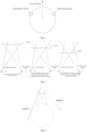
- the obstacle detector disposed at the cleaning robot should include a second obstacle detector and a third obstacle detector which are symmetrically disposed at two sides of a body of the cleaning robot, as shown in Fig. 3 . Obstacles in a detection blind zone of the first obstacle detector may be detected by the second obstacle detector and the third obstacle detector, which ensures that all the obstacles that may collide with the cleaning robot in the moving direction or at both sides of the moving direction can be detected during moving.
- the obstacle detector disposed at the cleaning robot may include a second obstacle detector and a third obstacle detector only.
- the second obstacle detector and the third obstacle detector are symmetrically disposed at two sides of a body of the cleaning robot, and an angle between each detector and the moving direction is in a range of 0 to ⁇ , where ⁇ is from 45° to 90°, as shown in Fig. 4 .
- all the obstacles that may collide with the cleaning robot in the moving direction or at both sides of the moving direction can be detected during moving.
- the obstacle detector of the cleaning robot When the cleaning robot is in a working state, the obstacle detector of the cleaning robot also remains working to detect whether there is an obstacle that may collide with the cleaning robot. When the obstacle is detected, detection data for the obstacle is acquired.
- the obstacle detector includes a signal transmitting module and a signal receiving module which are arranged according to a preset angle and a preset distance.
- the signal transmitting module radiates a first signal outward, and the signal receiving module receives a second signal sent back from the obstacle after the first signal is transmitted to the obstacle.
- Fig. 5 is a schematic diagram illustrating a working principle of an obstacle detector according to an embodiment of the present disclosure. As shown in Fig. 5 , the signal transmitting module radiates a first signal outward, so as to form a first path between the signal transmitting module and the obstacle. The second signal forms a second path between the signal receiving module and the obstacle, and further convers into the detection data of the obstacle detector.
- a solid line refers to the first path formed by the first signal and a dotted line refers to the second path formed by the second signal.
- block 102 it is determined according to the detection data whether a distance between the cleaning robot and an obstacle reaches a first distance, where the first distance is a distance between the cleaning robot and the obstacle at a moment when a changing trend of the detection data fits a preset changing trend.
- the detection data includes the second signal reflected off the obstacle. After the detection data is acquired, the detection data is further analyzed, so as to identify a changing trend during the cleaning robot approaching the obstacle. In this embodiment, if the changing trend of the detection data fits a preset changing trend, the distance between the cleaning robot and the obstacle is determined as the first distance.
- the distance detection method for a cleaning robot provided in the embodiments of the present disclosure, it is precisely detected whether the cleaning robot is moving to a specific positon a certain distance away from the obstacle. As the specific position is determined precisely, collision with obstacles can be avoided efficiently for the cleaning robot during working, and thus the distance detection method for the cleaning robot is improved.
- a step of determining, according to the detection data, whether the distance between the cleaning robot and the obstacle reaches the first distance includes following steps.
- the second signal is extracted from the detection data, the second signal detected in a period that the cleaning robot is moving is analyzed, and a changing trend of a signal intensity of the second signal is acquired.
- a distance between the cleaning robot and the obstacle at a current moment is acquired if the changing trend is determined to fit the preset changing trend, where the distance at the current moment is the first distance.
- the detection data includes a second signal. After the second signal is extracted from the detection data, the signal intensity of the second signal is acquired according to reception time of the second signal. Then, the changing trend is identified to determine whether it fits the preset changing trend that the signal intensity is increased first and then decreased. If the identified changing trend fits the preset changing trend, according to the signal intensity at the current moment, a corresponding distance between the cleaning robot and the obstacle at the current moment is acquired.
- the current moment is a moment when the signal intensity of the second signal is determined to be decreased. It is known from the above that when the signal intensity of the second signal is a maximum, the distance between the cleaning robot and the obstacle is the first distance, that is, the distance between the cleaning robot and the obstacle at the current moment is the first distance.
- such a step specifically includes: acquiring the distance between the cleaning robot and the obstacle at the current moment according to the signal intensity of the second signal at the current moment.
- the signal intensity of the second signal has a one to one corresponding relationship with the distance between the cleaning robot and the obstacle (i.e., the first distance), that is, a different signal intensity of the second signal corresponds to a different distance value, and the distance value is the distance between the cleaning robot and the obstacle.
- the corresponding relationship is acquired by means of experimental acquisition during the development process of the cleaning robot. After an intensity of the second signal at the current moment is acquired, the distance between the cleaning robot and the obstacle can be acquired by querying the corresponding relationship.
- Angle and distance between the signal transmitting module and the signal receiving module in the figure can be preset such that the overlapping area between the two paths is increase first and then decreased. Specifically, during the process of the cleaning robot gradually approaching the obstacle from a distance, since the overlapping area between the first path and the second path is increased first and then decreased, that is, an area of the obstacle surface reflecting the first signal is first increased and then decreased as the cleaning robot approaches the obstacle, the signal intensity of the second signal is increased first and then decreased as the cleaning robot approaches the obstacle. Specifically, the larger the area of the obstacle surface reflecting the first signal is, the higher the intensity of the second signal generated by the reflection of the first signal is, otherwise, the lower the intensity of the second signal is.
- the overlapping area reaches a maximum and will start to be decrease as the cleaning robot further approaches.
- a maximum signal intensity of the second signal is acquired, and the certain distance is the first distance between the cleaning robot and the obstacle.
- the distance detection method for a cleaning robot provided in the embodiments of the present disclosure, it is precisely detected whether the cleaning robot is moving to a specific positon a certain distance away from the obstacle. As the specific position is determined precisely, collision with obstacles can be avoided efficiently for the cleaning robot during working, and thus the distance detection method for the cleaning robot is improved.
- the first obstacle detector When the cleaning robot is moving in a direction perpendicular to the obstacle, the first obstacle detector is able to complete the corresponding detecting work.
- the cleaning robot When the moving direction of the cleaning robot is not perpendicular to the obstacle, two situations may happen.
- the acute angle between the moving direction of the cleaning robot and the obstacle is relatively large, as shown in Fig. 6 , the obstacle is an obstacle 1 represented by the dotted line.
- the overlapping area formed by the first signal and the second signal is increased first and then decreased. After the point A, the overlapping area becomes smaller, and the signal intensity of the second signal also becomes smaller, that is, the first distance is reached when the obstacle reaches the point A.
- the cleaning robot is close to the obstacle, but does not collide with the obstacle, and thus the cleaning robot can stop normally.
- the first obstacle detector is enough to complete the corresponding detecting work.
- the acute angle between the moving direction of the cleaning robot and the obstacle is relatively small, as shown in Fig. 6 , the obstacle is an obstacle 2 represented by the solid line.
- the overlapping area is increased.
- the cleaning robot may have collided with the obstacle.
- the first obstacle detector cannot realize the distance control of the obstacle at that angle. Therefore, the second obstacle detector and the third obstacle detector are required to be disposed at the two sides of the cleaning robot.
- a minimum of the signal intensity of the second signal may be set to realize a switch from the first obstacle detector being working to the second and third obstacle detectors being working.
- a signal intensity of the second signal corresponding to a case where the obstacle passes the point A and is tangential to the cleaning robot is a minimum signal intensity threshold that the cleaning robot is able to stop by itself.
- the signal intensity of the second signal is detected to be decreased to such a threshold, the first obstacle detector stops working immediately, and the second obstacle detector and the third obstacle detector are turned on. Specifically, a detector that has not received any obstacle information within a certain period is turned off, and another detector may continuously detect the obstacle.
- the obstacle detector may be switched to continue the detection without determining whether the first obstacle detector is feasible or not. All obstacle detectors may be turned on. If an acute angle between the detection axis of an obstacle detector and the obstacle is closer to 0°, the first distance will be reached sooner for such an obstacle detector, and the signal intensity of the second signal will be higher when the first distance is reached.
- the cleaning robot stops moving, so that the current first distance of the cleaning robot is as close as possible to an optimal distance of the cleaning robot from the obstacle.
- the optimal distance is the first distance when the moving direction of the cleaning robot is perpendicular to the obstacle. At such a first distance, the cleaning robot stops at the farthest distance from the obstacle, thus efficiently prevent the cleaning robot from colliding with the obstacle.
- the two obstacle detectors may be activated once at a preset time interval, where a product of the time length of the interval and a speed of the cleaning robot is less than a distance from detection of the obstacle to the collision with the obstacle in any case, so as to detect whether there is an obstacle in front.
- the overlapping of the paths may be decreased or even disappear as the distance between the cleaning robot and the obstacle is increased, such that the obstacle detector has a limited detection direction. If no obstacle is detected within the detection distance, the obstacle detector will be turned off again and wait for the preset time interval to restart the detection. When an obstacle is detected in the detection range, the obstacle detector remains working for continuous detection until the cleaning robot reaches the first distance from the obstacle and then be turned off.
- the changing trends of the signal intensities of the second signals of both detectors are acquired. If any of the signal intensities starts to decrease, it is determined that the cleaning robot arrives at the first distance from the obstacle and stops moving. Specifically, when the signal intensities of the second signals of the two detectors are the same, it is determined that the obstacle is perpendicular to the moving direction of the cleaning robot.
- Fig. 7 is a flow chart of a distance detection method for a cleaning robot according to another embodiment of the present disclosure. As shown in Fig. 7 , in order to solve the above problem, the following steps are specifically included.
- the cleaning robot is controlled to continue to advance and it is returned to perform the step of acquiring the detection data and subsequent steps.
- the cleaning robot is controlled to continue to advance. Moreover, steps of acquiring detection data of an obstacle detector of the cleaning robot, and determining, according to the detection data, whether the distance between the cleaning robot and the obstacle reaches the first distance as described above are repeated until it is determined that the distance between the cleaning robot and the obstacle reaches the first distance.
- the cleaning robot is controlled to rotate in situ, such that a moving direction of the cleaning robot is parallel to a contour line of the obstacle or a tangent line of a contour line of the obstacle.
- the cleaning robot is controlled to move in the moving direction, and the distance between the cleaning robot and the obstacle during the moving is controlled to be maintained within a preset distance range.
- the steps of acquiring detection data of an obstacle detector of the cleaning robot, and determining, according to the detection data, whether the distance between the cleaning robot and the obstacle reaches the first distance as described above are repeated.
- the cleaning robot is controlled to stop, and it is determined according to identifier information of an obstacle detector of the detection data whether the cleaning robot should rotate clockwise or counterclockwise in situ.
- identifier information of an obstacle detector of the detection data whether the cleaning robot should rotate clockwise or counterclockwise in situ.
- the cleaning robot is controlled to rotate, in a corresponding clockwise or counterclockwise direction, an angular displacement of an acute angle between the moving direction of the cleaning robot and the obstacle.
- the moving direction after the rotation of the cleaning robot is parallel to the contour line of the obstacle or the tangent line thereof, so that the cleaning robot may continue to move along the direction parallel to the contour line of the obstacle or the tangent line thereof.
- a distance sensor may be disposed at the two sides of the cleaning robot to monitor the distance between the cleaning robot and the obstacle during moving in real time, so that the distance between the cleaning robot and the obstacle during the moving is maintained within the preset distance range.
- the rotation direction may be randomly selected, or the obstacle detectors on both sides of the body of the cleaning robot may be used to detect the surroundings so as to enable the cleaning robot to rotate to a side with fewer obstacles preferentially, thus preventing the cleaning robot from collision with the obstacles and reducing times of adjustments of the moving direction of the cleaning robot during cleaning process.
- the detection data further includes identifier information of an obstacle detector.
- identifier information of an obstacle detector By extracting the identifier information of the detector from the detection data, a general direction of an obstacle related to the obstacle detector may be determined as follows.
- the identifier information of the detector is extracted from the detection data, and a target obstacle detector to which the detection data belongs is identified according to the identifier information.
- a relative positional relationship between the cleaning robot and the obstacle is determined according to a position where the target obstacle detector is disposed at the cleaning robot.
- the identifier information of the obstacle detector is extracted from the detection data, and the position where the obstacle detector is located is also considered.
- the detection data includes the identifier information of the second obstacle detector but does not include the identifier information of the third obstacle detector, it indicates that the current detection data is acquired by the second obstacle detector.
- the second obstacle detector is disposed at a front-left side of the cleaning robot, the cleaning robot thus can determine that the obstacle is in front-left of the cleaning robot.
- the claning root reaches the first distance from the obstacle, it stops and rotates clockwise in situ, such that the cleaning robot may rotate a minimum angle to make the moving direction of the cleaning robot in consistency with the contour of the obstacle or the tangent line thereof.
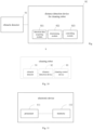
- Fig. 9 is a block diagram of a distance detection device for a cleaning robot according to an embodiment of the present disclosure. Specifically, an obstacle detector 91 and the distance detection device 92 are disposed at the cleaning robot. The obstacle detector 91 is configured to detect an obstacle, and the obstacle detector 91 is connected to the distance detection device 92.
- the distance detection device 92 includes: a detection data acquiring module 921 configured to acquire detection data of the obstacle detector of the cleaning robot, and a determining module 922 configured to determine, according to the detection data, whether a distance between the cleaning robot and an obstacle reaches a first distance, where the first distance is a distance between the cleaning robot and the obstacle at a moment when a changing trend of the detection data fits in a preset changing trend.
- each obstacle detector 91 includes a signal transmitting module and a signal receiving module, where the signal transmitting module and the signal receiving module are arranged according to preset angle and a preset distance, such that an overlapping area exists between a first path and a second path, the first path being formed between the signal transmitting module and the obstacle and the second path being formed between the signal receiving module and the obstacle, and the overlapping area reaches a maximum when the distance between the cleaning robot and the obstacle reaches the first distance.
- the obstacle detector 91 includes a first obstacle detector disposed at a forward end of the cleaning robot.
- the obstacle detector 91 further includes a second obstacle detector and a third obstacle detector, and the second obstacle detector and the third obstacle detector are symmetrically disposed at two sides of a body of the cleaning robot.
- the obstacle detector includes a second obstacle detector and a third obstacle detector, and the second obstacle detector and the third obstacle detector are symmetrically disposed at two sides of a body of the cleaning robot.
- the signal transmitting module included in the obstacle detector 91 is configured to radiate first signal outward, and the corresponding signal receiving module is configured to receive second signal sent back from the obstacle which the first signal is transmitted to the obstacle.
- the detection data includes the second signal.
- the determining module 922 is specifically configured to:
- the determining module 922 is further configured to: acquire the distance between the cleaning robot and the obstacle according to the signal intensity of the second signal at the current moment, where the current moment is a moment when the signal intensity of the second signal is determined to be decreased.
- the distance detection device 92 includes: a controlling module 923 connected to the determining module 922 and the detection data acquiring module 921.
- the controlling module 923 is configured to control the cleaning robot to continue to advance and return to perform the process of acquiring the detection data and subsequent processes.
- the controlling module is configured to control the cleaning robot to rotate in situ, such that a moving direction of the cleaning robot is parallel to a boundary line of the obstacle or a tangent line of a boundary line of the obstacle, and control the cleaning robot to move in the moving direction.
- controlling module 923 is further configured to:
- Fig. 10 is a block diagram of a cleaning robot according to an embodiment of the present disclosure. As shown in Fig. 10 , an obstacle detector 91, a distance detection device 92 as described above and a cleaning control device 93 are disposed at the cleaning robot. The distance detection device 92 is connected to the cleaning control device 93.
- the obstacle detector 91 is configured to detect an obstacle
- the cleaning control device 93 is configured to perform a cleaning operation.
- Fig. 11 is a block diagram of an electronic device according to an embodiment of the present disclosure. As shown in Fig. 11 , the electronic device includes a processor 111 and a memory 112.
- the processor 112 reads an executable program code stored in the memory 111 to execute a program corresponding to the executable program code, so as to perform a distance detection method for a cleaning robot as described in the above embodiments of the present disclosure.
- the present disclosure provides a non-transitory computer readable storage medium having stored therein a computer program that, when executed by a processor, causes the processor to perform a distance detection method for a cleaning robot as described in the above embodiments of the present disclosure.
- first and second are used herein for purposes of description and are not intended to indicate or imply relative importance or significance or to imply the number of indicated technical features.
- the feature defined with “first” and “second” may include one or more of this feature.
- a plurality of means two or more than two.
- the terms “mounted”, “connected”, “coupled”, “fixed” and the like are used broadly, and may be, for example, fixed connections, detachable connections, or integral connections; may also be mechanical or electrical connections; may also be direct connections or indirect connections via intervening structures; may also be inner communications of two elements, which can be understood by those skilled in the art according to specific situations.
- a structure in which a first feature is "on" or “below” a second feature may include an embodiment in which the first feature is in direct contact with the second feature, and may also include an embodiment in which the first feature and the second feature are not in direct contact with each other, but are contacted via an additional feature formed therebetween.
- a first feature "on”, “above” or “on top of” a second feature may include an embodiment in which the first feature is right or obliquely “on”, “above” or “on top of” the second feature, or just means that the first feature is at a height higher than that of the second feature; while a first feature “below”, “under” or “on bottom of” a second feature may include an embodiment in which the first feature is right or obliquely “below”, “under” or “on bottom of” the second feature, or just means that the first feature is at a height lower than that of the second feature.
Landscapes
- Engineering & Computer Science (AREA)
- Radar, Positioning & Navigation (AREA)
- Remote Sensing (AREA)
- Physics & Mathematics (AREA)
- General Physics & Mathematics (AREA)
- Automation & Control Theory (AREA)
- Computer Networks & Wireless Communication (AREA)
- Aviation & Aerospace Engineering (AREA)
- Electromagnetism (AREA)
- Acoustics & Sound (AREA)
- Game Theory and Decision Science (AREA)
- Business, Economics & Management (AREA)
- Health & Medical Sciences (AREA)
- Artificial Intelligence (AREA)
- Evolutionary Computation (AREA)
- Medical Informatics (AREA)
- Robotics (AREA)
- Control Of Position, Course, Altitude, Or Attitude Of Moving Bodies (AREA)
- Manipulator (AREA)
Claims (12)
- Computerimplementiertes Abstandserkennungsverfahren für einen Reinigungsroboter, umfassend:Erhalten (101) von Erfassungsdaten eines Hindernisdetektors des Reinigungsroboters,Bestimmen (102), gemäß den Erfassungsdaten, ob ein Abstand zwischen dem Reinigungsroboter und einem Hindernis einen ersten Abstand erreicht, wobei der erste Abstand ein Abstand zwischen dem Reinigungsroboter und dem Hindernis zu einem Zeitpunkt ist, an dem ein Änderungstrend der Erfassungsdaten einem voreingestellten Änderungstrend entspricht,wobei der Hindernisdetektor ein Signalsendemodul und ein Signalempfangsmodul umfasst, wobei das Signalsendemodul und das Signalempfangsmodul gemäß einem voreingestellten Winkel und einem voreingestellten Abstand angeordnet sind, so dass ein Überlappungsbereich zwischen einem ersten Pfad und einem zweiten Pfad besteht, wobei der erste Pfad ein Bereich ist, der von einem ersten Signal abgedeckt wird, das zwischen dem Signalsendemodul und dem Hindernis übertragen wird, und der zweite Pfad ein Bereich ist, der von einem zweiten Signal abgedeckt wird, das zwischen dem Signalempfangsmodul und dem Hindernis übertragen wird,wobei das Signalsendemodul das erste Signal nach außen abstrahlt und das Signalempfangsmodul das zweite Signal empfängt, das von dem Hindernis zurückgesendet wird, nachdem das erste Signal das Hindernis erreicht; wobei die Erfassungsdaten das zweite Signal umfassen;dadurch gekennzeichnet, dassder Überlappungsbereich ein Maximum erreicht, wenn der Abstand zwischen dem Reinigungsroboter und dem Hindernis den ersten Abstand erreicht, der voreingestellte Änderungstrend darin besteht, dass eine Signalintensität des zweiten Signals zuerst erhöht und dann verringert wird,und dass das Bestimmen (102) gemäß den Erfassungsdaten, ob der Abstand zwischen dem Reinigungsroboter und dem Hindernis den ersten Abstand erreicht, Folgendes umfasst:Extrahieren des zweiten Signals aus den Erfassungsdaten, Analysieren des zweiten Signals, das in einem Zeitraum erfasst wird, in dem sich der Reinigungsroboter bewegt, und Erhalten eines Änderungstrends einer Signalintensität des zweiten Signals,Bestimmen, ob der Änderungstrend mit dem voreingestellten Änderungstrend übereinstimmt, undErhalten eines Abstands zwischen dem Reinigungsroboter und dem Hindernis zu einem aktuellen Zeitpunkt, wenn der Änderungstrend so bestimmt wird, dass er mit dem voreingestellten Änderungstrend übereinstimmt, wobei der Abstand zu dem aktuellen Zeitpunkt der erste Abstand ist.
- Verfahren gemäß Anspruch 1, wobei der Hindernisdetektor einen ersten Hindernisdetektor umfasst, der sich an einem vordersten Ende des Reinigungsroboters befindet.
- Verfahren gemäß Anspruch 1 oder 2, wobei der Hindernisdetektor ferner einen zweiten Hindernisdetektor und einen dritten Hindernisdetektor umfasst, wobei der zweite Hindernisdetektor und der dritte Hindernisdetektor symmetrisch an zwei Seiten eines Körpers des Reinigungsroboters angeordnet sind.
- Verfahren gemäß einem der Ansprüche 1 bis 3, wobei das Erhalten des Abstands zwischen dem Reinigungsroboter und dem Hindernis zum aktuellen Zeitpunkt Folgendes umfasst:Erhalten des Abstands zwischen dem Reinigungsroboter und dem Hindernis gemäß der Signalintensität des zweiten Signals zum aktuellen Zeitpunkt, wobei der aktuelle Zeitpunkt ein Zeitpunkt ist, an dem die Signalintensität des zweiten Signals als verringert bestimmt wird, und/oderwenn der Abstand zwischen dem Reinigungsroboter und dem Hindernis den ersten Abstand nicht erreicht, Steuern (301) des Reinigungsroboters, sodass er weiterfährt und zurückkehrt, um den Erhalt der Erfassungsdaten und die nachfolgenden Schritte durchzuführen;wenn der Abstand zwischen dem Reinigungsroboter und dem Hindernis den ersten Abstand erreicht,Steuern (302) des Reinigungsroboters, sodass er sich an Ort und Stelle dreht, so dass eine Bewegungsrichtung des Reinigungsroboters parallel zu einer Konturlinie des Hindernisses oder einer Tangente an eine Konturlinie des Hindernisses verläuft, undSteuern (303) des Reinigungsroboters, so dass er sich in die Bewegungsrichtung bewegt, wobei der Abstand zwischen dem Reinigungsroboter und dem Hindernis während der Bewegung so gesteuert wird, dass er innerhalb eines voreingestellten Abstandsbereichs gehalten wird.
- Verfahren gemäß einem der Ansprüche 1 bis 4, ferner umfassend:Extrahieren von Identifizierungsinformationen des Hindernisdetektors aus den Erfassungsdaten und Identifizieren eines Ziel-Hindernisdetektors, zu dem die Erfassungsdaten gehören, gemäß den Identifizierungsinformationen, undBestimmen einer relativen Positionsbeziehung zwischen dem Reinigungsroboter und dem Hindernis gemäß einer Position, an der sich der Ziel-Hindernisdetektor auf dem Reinigungsroboter befindet.
- Abstandserkennungsvorrichtung für einen Reinigungsroboter, wobei ein Hindernisdetektor an dem Reinigungsroboter angeordnet ist und so konfiguriert ist, dass er ein Hindernis erkennt; der Hindernisdetektor ist mit der Abstandserkennungsvorrichtung verbunden;
die Vorrichtung zur Abstandserkennung umfasst Folgendes:ein Erfassungsdatenerhaltmodul (921), das so konfiguriert ist, dass es Erfassungsdaten des Hindernisdetektors des Reinigungsroboters erhält,ein Bestimmungsmodul (922), das so konfiguriert ist, dass es gemäß den Erfassungsdaten bestimmt, ob ein Abstand zwischen dem Reinigungsroboter und einem Hindernis einen ersten Abstand erreicht, wobei der erste Abstand ein Abstand zwischen dem Reinigungsroboter und dem Hindernis in einem Moment ist, in dem ein Änderungstrend der Erfassungsdaten mit einem voreingestellten Änderungstrend übereinstimmt, wobei der Hindernisdetektor ein Signalsendemodul und ein Signalempfangsmodul umfasst, wobei das Signalsendemodul und das Signalempfangsmodul gemäß einem voreingestellten Winkel und einem voreingestellten Abstand angeordnet sind,so dass ein Überlappungsbereich zwischen einem ersten Pfad und einem zweiten Pfad existiert, wobei der erste Pfad ein Bereich ist, der von einem ersten Signal abgedeckt wird, das zwischen dem Signalsendemodul und dem Hindernis übertragen wird, und wobei der zweite Pfad ein Bereich ist, der von einem zweiten Signal abgedeckt wird, das zwischen dem Signalempfangsmodul und dem Hindernis übertragen wird, und der Überlappungsbereich ein Maximum erreicht, wenn der Abstand zwischen dem Reinigungsroboter und dem Hindernis den ersten Abstand erreicht, wobei das Signalsendemodul so konfiguriert ist, dass es das erste Signal nach außen abstrahlt, und das Signalempfangsmodul so konfiguriert ist, dass es das zweite Signal empfängt, das von dem Hindernis zurückgesendet wird, welches das erste Signal das Hindernis erreicht; wobei die Detektionsdaten das zweite Signal umfassen;dadurch gekennzeichnet, dassder voreingestellte Änderungstrend darin besteht, dass eine Signalintensität des zweiten Signals zunächst erhöht und dann verringert wird,das Bestimmungsmodul (922) speziell konfiguriert ist zum:Extrahieren des zweiten Signals aus den Erfassungsdaten, Analysieren des zweiten Signals, das in einem Zeitraum erfasst wurde, in dem sich der Reinigungsroboter bewegt, und Erfassen eines Änderungstrends einer Signalintensität des zweiten Signals,Bestimmen, ob der Änderungstrend der voreingestellte Änderungstrend ist,
undErhalten eines Abstands zwischen dem Reinigungsroboter und dem Hindernis zu einem aktuellen Zeitpunkt, wenn der Änderungstrend als der voreingestellte Änderungstrend bestimmt wird, wobei der Abstand zu dem aktuellen Zeitpunkt der erste Abstand ist. - Vorrichtung gemäß Anspruch 6, wobei der Hindernisdetektor einen ersten Hindernisdetektor umfasst, der sich an einem vordersten Ende des Reinigungsroboters befindet.
- Vorrichtung gemäß Anspruch 6 oder 7, wobei der Hindernisdetektor ferner einen zweiten Hindernisdetektor und einen dritten Hindernisdetektor umfasst, wobei der zweite Hindernisdetektor und der dritte Hindernisdetektor symmetrisch an zwei Seiten eines Körpers des Reinigungsroboters angeordnet sind.
- Vorrichtung gemäß einem der Ansprüche 6 bis 8, und das Bestimmungsmodul ist ferner so konfiguriert zum:Erhalten des Abstands zwischen dem Reinigungsroboter und dem Hindernis gemäß der Signalintensität des zweiten Signals zum aktuellen Zeitpunkt, wobei der aktuelle Zeitpunkt ein Zeitpunkt ist, an dem die Signalintensität des zweiten Signals als verringert bestimmt wird, und/oderweiterhin umfassend: ein Steuermodul (923), das mit dem Bestimmungsmodul und dem Erfassungsdatenerhaltmodul verbunden ist, wobei wenn der Abstand zwischen dem Reinigungsroboter und dem Hindernis den ersten Abstand nicht erreicht, das Steuermodul konfiguriert ist zum:Steuern des Reinigungsroboters, so dass er weiterfährt und zurückkehrt, um den Prozess des Erhaltens der Erkennungsdaten und die nachfolgenden Prozesse durchzuführen;wenn der Abstand zwischen dem Reinigungsroboter und dem Hindernis den ersten Abstand erreicht, das Steuermodul konfiguriert ist zum:Steuern des Reinigungsroboters, so dass er sich an Ort und Stelle dreht, so dass eine Bewegungsrichtung des Reinigungsroboters parallel zu einer Konturlinie des Hindernisses oder einer Tangente an eine Konturlinie des Hindernisses verläuft, undSteuern des Reinigungsroboters, so dass er sich in die Bewegungsrichtung bewegt, wobei der Abstand zwischen dem Reinigungsroboter und dem Hindernis während der Bewegung so gesteuert wird, dass er innerhalb eines voreingestellten Abstandsbereichs gehalten wird.
- Vorrichtung gemäß einem der Ansprüche 6 bis 9, die ferner konfiguriert ist zum:Extrahieren von Identifizierungsinformationen des Hindernisdetektors aus den Erfassungsdaten und Identifizieren eines Ziel-Hindernisdetektors, zu dem die Erfassungsdaten gehören, gemäß den Identifizierungsinformationen, undBestimmen einer relativen Positionsbeziehung zwischen dem Reinigungsroboter und dem Hindernis gemäß einer Position, an der der Ziel-Hindernisdetektor an dem Reinigungsroboter angeordnet ist.
- Reinigungsroboter, umfassend: einen Hindernisdetektor (91), eine Reinigungsvorrichtung und eine Abstandserkennungsvorrichtung (92) gemäß einem der Ansprüche 6 bis 10, die sich an dem Reinigungsroboter befinden, wobei der Hindernisdetektor (91) mit der Reinigungsvorrichtung und mit der Abstandserkennungsvorrichtung (92) verbunden ist und die Abstandserkennungsvorrichtung (92) mit der Reinigungsvorrichtung verbunden ist;
wobei der Hindernisdetektor (91) so konfiguriert ist, dass er ein Hindernis erkennt, und die Reinigungsvorrichtung so konfiguriert ist, dass sie einen Reinigungsvorgang durchführt. - Nicht-transitorisches computerlesbares Speichermedium, auf dem ein Computerprogramm gespeichert ist, das, wenn es von einem Prozessor (111) ausgeführt wird, den Prozessor (111) veranlasst, ein Abstandserkennungsverfahren für einen Reinigungsroboter gemäß einem der Ansprüche 1 bis 5 durchzuführen.
Applications Claiming Priority (1)
| Application Number | Priority Date | Filing Date | Title |
|---|---|---|---|
| CN201811495536.XA CN109407670B (zh) | 2018-12-07 | 2018-12-07 | 扫地机器人的距离探测方法及其装置和扫地机器人 |
Publications (2)
| Publication Number | Publication Date |
|---|---|
| EP3663795A1 EP3663795A1 (de) | 2020-06-10 |
| EP3663795B1 true EP3663795B1 (de) | 2024-02-21 |
Family
ID=65457822
Family Applications (1)
| Application Number | Title | Priority Date | Filing Date |
|---|---|---|---|
| EP19214006.9A Active EP3663795B1 (de) | 2018-12-07 | 2019-12-06 | Abstandsdetektionsverfahren und -vorrichtung für reinigungsroboter und reinigungsroboter |
Country Status (3)
| Country | Link |
|---|---|
| US (1) | US11474526B2 (de) |
| EP (1) | EP3663795B1 (de) |
| CN (1) | CN109407670B (de) |
Families Citing this family (15)
| Publication number | Priority date | Publication date | Assignee | Title |
|---|---|---|---|---|
| CN111766607A (zh) * | 2019-03-13 | 2020-10-13 | 科沃斯机器人股份有限公司 | 一种自移动设备和非接触式障碍物检测装置 |
| CN110244743B (zh) * | 2019-07-03 | 2022-02-01 | 浙江大学 | 一种融合多传感器信息的移动机器人自主脱困方法 |
| CN110597260A (zh) * | 2019-09-20 | 2019-12-20 | 深圳乐动机器人有限公司 | 一种机器人避障的方法及机器人 |
| CN110989621B (zh) * | 2019-12-20 | 2025-05-20 | 深圳市杉川机器人有限公司 | 自主机器人的控制方法及自主机器人 |
| CN111708360B (zh) * | 2020-05-15 | 2023-01-31 | 科沃斯机器人股份有限公司 | 信息采集方法、设备及存储介质 |
| CN114451814B (zh) * | 2020-11-10 | 2023-12-08 | 苏州宝时得电动工具有限公司 | 自动行走设备和自动行走设备的控制方法 |
| CN112486184B (zh) * | 2020-12-10 | 2023-08-11 | 北京小狗吸尘器集团股份有限公司 | 一种扫地机器人及其避障路径确定方法 |
| CN112528959B (zh) * | 2020-12-29 | 2024-06-07 | 上海同温层信息科技有限公司 | 用于清洁机器人的障碍物识别方法 |
| EP4059403B8 (de) * | 2021-01-19 | 2023-12-27 | Yituo Electric Co., Ltd. | Steuerverfahren und steuervorrichtung eines reinigungsgeräts |
| CN115191868B (zh) * | 2021-04-09 | 2024-06-14 | 美智纵横科技有限责任公司 | 沿边清洁方法及清洁机器人 |
| US20250060756A1 (en) * | 2021-09-15 | 2025-02-20 | Nidec Corporation | Autonomous traveling device and autonomous traveling device control method |
| CN116138653A (zh) * | 2021-11-22 | 2023-05-23 | 追觅创新科技(苏州)有限公司 | 清洁设备的运行控制方法及装置、存储介质及电子装置 |
| CN115562309A (zh) * | 2022-11-03 | 2023-01-03 | 上海高仙自动化科技发展有限公司 | 一种机器人会车方法、控制器、存储介质及机器人 |
| CN119138802B (zh) * | 2023-06-12 | 2025-10-03 | 珠海一微半导体股份有限公司 | 用于非圆形清洁机器人的碰撞预测方法 |
| CN117471478A (zh) * | 2023-10-31 | 2024-01-30 | 烟台艾睿光电科技有限公司 | 位置信息显示方法、装置、设备及介质 |
Family Cites Families (23)
| Publication number | Priority date | Publication date | Assignee | Title |
|---|---|---|---|---|
| GB582708A (en) * | 1942-04-03 | 1946-11-26 | Standard Telephones Cables Ltd | Improvements in arrangements for obstacle detection and measurement of distances by electromagnetic waves |
| US8412377B2 (en) * | 2000-01-24 | 2013-04-02 | Irobot Corporation | Obstacle following sensor scheme for a mobile robot |
| KR100633444B1 (ko) * | 2005-02-24 | 2006-10-13 | 삼성광주전자 주식회사 | 로봇 청소기 및 그 제어 방법 |
| KR100692897B1 (ko) * | 2005-10-28 | 2007-03-12 | 엘지전자 주식회사 | 이동로봇 |
| JP2010099366A (ja) * | 2008-10-27 | 2010-05-06 | Panasonic Corp | 自走式掃除機 |
| US20120065829A1 (en) * | 2010-09-15 | 2012-03-15 | Jyh-Cheng Yu | Wall-following Moving Device |
| US9020641B2 (en) * | 2012-06-07 | 2015-04-28 | Samsung Electronics Co., Ltd. | Obstacle sensing module and cleaning robot including the same |
| CN104007765B (zh) * | 2014-06-16 | 2016-05-04 | 成都北斗群星智能科技有限公司 | 扫地机器人避障、定位方法 |
| JP6453583B2 (ja) * | 2014-08-20 | 2019-01-16 | 東芝ライフスタイル株式会社 | 電気掃除機 |
| EP3186658B1 (de) * | 2014-10-31 | 2021-02-24 | Siemens Schweiz AG | Verfahren, digitales werkzeug, vorrichtung und system zur entdeckung/erkennung von sich wiederholenden bewegungen, insbesondere rhythmischen gesten, in einem funkbereich, insbesondere einem innenraum, mit mindestens einer bewegungsgeschwindigkeit und jeweils zumindest einer wiederholung |
| CN104765363B (zh) * | 2014-12-10 | 2018-04-24 | 深圳市银星智能科技股份有限公司 | 智能扫地机器人及其控制方法 |
| CN105223951B (zh) * | 2015-09-14 | 2018-01-26 | 苏州爱普电器有限公司 | 自移动机器人 |
| CN105955304B (zh) * | 2016-07-06 | 2024-11-08 | 零度智控(北京)智能科技有限公司 | 一种避障方法、避障装置及无人飞行器 |
| JP6931994B2 (ja) * | 2016-12-22 | 2021-09-08 | パナソニック インテレクチュアル プロパティ コーポレーション オブ アメリカPanasonic Intellectual Property Corporation of America | 自律移動体、移動制御方法及び移動制御プログラム |
| CN106725127B (zh) * | 2017-02-04 | 2020-06-02 | 北京小米移动软件有限公司 | 扫地机器人的清扫方法及装置 |
| TW201833701A (zh) * | 2017-03-14 | 2018-09-16 | 聯潤科技股份有限公司 | 自走式清潔裝置及其建立室內地圖之方法 |
| CN106821157A (zh) * | 2017-04-14 | 2017-06-13 | 小狗电器互联网科技(北京)股份有限公司 | 一种扫地机器人扫地的清扫方法 |
| JP7007108B2 (ja) * | 2017-05-23 | 2022-01-24 | 東芝ライフスタイル株式会社 | 電気掃除機 |
| CN107450569A (zh) * | 2017-09-27 | 2017-12-08 | 上海思岚科技有限公司 | 一种扫地机器人的控制方法及设备 |
| CN107831766A (zh) * | 2017-10-30 | 2018-03-23 | 北京奇虎科技有限公司 | 机器人的碰撞处理方法、装置及机器人 |
| CN107775640B (zh) * | 2017-12-05 | 2024-06-18 | 深圳银星智能集团股份有限公司 | 移动机器人 |
| CN109464075A (zh) | 2018-12-07 | 2019-03-15 | 江苏美的清洁电器股份有限公司 | 扫地机器人的清扫控制方法及其装置和扫地机器人 |
| CN109567678B (zh) | 2018-12-07 | 2022-03-04 | 美智纵横科技有限责任公司 | 扫地机器人的清扫控制方法及其装置和扫地机器人 |
-
2018
- 2018-12-07 CN CN201811495536.XA patent/CN109407670B/zh active Active
-
2019
- 2019-12-03 US US16/701,158 patent/US11474526B2/en active Active
- 2019-12-06 EP EP19214006.9A patent/EP3663795B1/de active Active
Also Published As
| Publication number | Publication date |
|---|---|
| US20200183404A1 (en) | 2020-06-11 |
| EP3663795A1 (de) | 2020-06-10 |
| CN109407670A (zh) | 2019-03-01 |
| US11474526B2 (en) | 2022-10-18 |
| CN109407670B (zh) | 2022-03-04 |
Similar Documents
| Publication | Publication Date | Title |
|---|---|---|
| US11474526B2 (en) | Distance detection method and device for cleaning robot, and cleaning robot | |
| US11278177B2 (en) | Cleaning control method and device for cleaning robot, and cleaning robot | |
| JP6597408B2 (ja) | 衝突緩和制御装置 | |
| CN109567678B (zh) | 扫地机器人的清扫控制方法及其装置和扫地机器人 | |
| US11679745B2 (en) | Rear-end collision avoidance apparatus and method, and vehicle control apparatus including same | |
| JP6592266B2 (ja) | 物体検知装置、及び物体検知方法 | |
| US20190232956A1 (en) | Vehicle control apparatus and vehicle control method | |
| JP6451623B2 (ja) | 走行支援装置 | |
| EP3398824B1 (de) | Automatisches bremssystem und verfahren zum betrieb eines automatischen bremssystems | |
| JP6319181B2 (ja) | 車両制御装置、及び車両制御方法 | |
| JP2015078926A (ja) | 物標検出装置 | |
| WO2016158989A1 (ja) | 車両制御装置、及び車両制御方法 | |
| WO2015097511A1 (en) | Vehicle surrounding situation estimation device | |
| JP2014213777A (ja) | 衝突緩和装置 | |
| CN113341417B (zh) | 基于探测雷达的路面障碍检测方法、车辆及存储介质 | |
| US10197672B2 (en) | Moving object detection apparatus and drive support apparatus | |
| WO2020237348A1 (en) | Selectable gesture detection system and methods | |
| KR102304601B1 (ko) | 자동주차 제어장치 및 그 방법 | |
| KR20180069019A (ko) | 물체 분류로 자동차의 주변 영역을 포착하는 방법, 제어 장치, 운전자 보조 시스템, 및 자동차 | |
| CN108973959B (zh) | 对于缓慢移动体的自动制动系统 | |
| JP4745151B2 (ja) | 移動ロボット | |
| CN118884952A (zh) | 自移动设备的避障方法及相关装置 | |
| JP4745150B2 (ja) | 移動ロボット | |
| KR20200040178A (ko) | 후방 충돌 방지 장치 및 방법과 그를 포함하는 차량 제어 장치 | |
| JP2017106806A (ja) | 物体認識装置 |
Legal Events
| Date | Code | Title | Description |
|---|---|---|---|
| PUAI | Public reference made under article 153(3) epc to a published international application that has entered the european phase |
Free format text: ORIGINAL CODE: 0009012 |
|
| STAA | Information on the status of an ep patent application or granted ep patent |
Free format text: STATUS: THE APPLICATION HAS BEEN PUBLISHED |
|
| AK | Designated contracting states |
Kind code of ref document: A1 Designated state(s): AL AT BE BG CH CY CZ DE DK EE ES FI FR GB GR HR HU IE IS IT LI LT LU LV MC MK MT NL NO PL PT RO RS SE SI SK SM TR |
|
| AX | Request for extension of the european patent |
Extension state: BA ME |
|
| STAA | Information on the status of an ep patent application or granted ep patent |
Free format text: STATUS: REQUEST FOR EXAMINATION WAS MADE |
|
| 17P | Request for examination filed |
Effective date: 20201027 |
|
| RBV | Designated contracting states (corrected) |
Designated state(s): AL AT BE BG CH CY CZ DE DK EE ES FI FR GB GR HR HU IE IS IT LI LT LU LV MC MK MT NL NO PL PT RO RS SE SI SK SM TR |
|
| RAP1 | Party data changed (applicant data changed or rights of an application transferred) |
Owner name: MIDEA ROBOZONE TECHNOLOGY CO., LTD. |
|
| STAA | Information on the status of an ep patent application or granted ep patent |
Free format text: STATUS: EXAMINATION IS IN PROGRESS |
|
| 17Q | First examination report despatched |
Effective date: 20220503 |
|
| GRAP | Despatch of communication of intention to grant a patent |
Free format text: ORIGINAL CODE: EPIDOSNIGR1 |
|
| STAA | Information on the status of an ep patent application or granted ep patent |
Free format text: STATUS: GRANT OF PATENT IS INTENDED |
|
| INTG | Intention to grant announced |
Effective date: 20231102 |
|
| GRAS | Grant fee paid |
Free format text: ORIGINAL CODE: EPIDOSNIGR3 |
|
| GRAA | (expected) grant |
Free format text: ORIGINAL CODE: 0009210 |
|
| STAA | Information on the status of an ep patent application or granted ep patent |
Free format text: STATUS: THE PATENT HAS BEEN GRANTED |
|
| AK | Designated contracting states |
Kind code of ref document: B1 Designated state(s): AL AT BE BG CH CY CZ DE DK EE ES FI FR GB GR HR HU IE IS IT LI LT LU LV MC MK MT NL NO PL PT RO RS SE SI SK SM TR |
|
| REG | Reference to a national code |
Ref country code: GB Ref legal event code: FG4D |
|
| REG | Reference to a national code |
Ref country code: CH Ref legal event code: EP |
|
| REG | Reference to a national code |
Ref country code: DE Ref legal event code: R096 Ref document number: 602019046846 Country of ref document: DE |
|
| REG | Reference to a national code |
Ref country code: IE Ref legal event code: FG4D |
|
| REG | Reference to a national code |
Ref country code: LT Ref legal event code: MG9D |
|
| P01 | Opt-out of the competence of the unified patent court (upc) registered |
Effective date: 20240520 |
|
| REG | Reference to a national code |
Ref country code: NL Ref legal event code: MP Effective date: 20240221 |
|
| PG25 | Lapsed in a contracting state [announced via postgrant information from national office to epo] |
Ref country code: IS Free format text: LAPSE BECAUSE OF FAILURE TO SUBMIT A TRANSLATION OF THE DESCRIPTION OR TO PAY THE FEE WITHIN THE PRESCRIBED TIME-LIMIT Effective date: 20240621 |
|
| PG25 | Lapsed in a contracting state [announced via postgrant information from national office to epo] |
Ref country code: LT Free format text: LAPSE BECAUSE OF FAILURE TO SUBMIT A TRANSLATION OF THE DESCRIPTION OR TO PAY THE FEE WITHIN THE PRESCRIBED TIME-LIMIT Effective date: 20240221 |
|
| PG25 | Lapsed in a contracting state [announced via postgrant information from national office to epo] |
Ref country code: GR Free format text: LAPSE BECAUSE OF FAILURE TO SUBMIT A TRANSLATION OF THE DESCRIPTION OR TO PAY THE FEE WITHIN THE PRESCRIBED TIME-LIMIT Effective date: 20240522 |
|
| REG | Reference to a national code |
Ref country code: AT Ref legal event code: MK05 Ref document number: 1659562 Country of ref document: AT Kind code of ref document: T Effective date: 20240221 |
|
| PG25 | Lapsed in a contracting state [announced via postgrant information from national office to epo] |
Ref country code: RS Free format text: LAPSE BECAUSE OF FAILURE TO SUBMIT A TRANSLATION OF THE DESCRIPTION OR TO PAY THE FEE WITHIN THE PRESCRIBED TIME-LIMIT Effective date: 20240521 Ref country code: NL Free format text: LAPSE BECAUSE OF FAILURE TO SUBMIT A TRANSLATION OF THE DESCRIPTION OR TO PAY THE FEE WITHIN THE PRESCRIBED TIME-LIMIT Effective date: 20240221 Ref country code: HR Free format text: LAPSE BECAUSE OF FAILURE TO SUBMIT A TRANSLATION OF THE DESCRIPTION OR TO PAY THE FEE WITHIN THE PRESCRIBED TIME-LIMIT Effective date: 20240221 |
|
| PG25 | Lapsed in a contracting state [announced via postgrant information from national office to epo] |
Ref country code: ES Free format text: LAPSE BECAUSE OF FAILURE TO SUBMIT A TRANSLATION OF THE DESCRIPTION OR TO PAY THE FEE WITHIN THE PRESCRIBED TIME-LIMIT Effective date: 20240221 |
|
| PG25 | Lapsed in a contracting state [announced via postgrant information from national office to epo] |
Ref country code: AT Free format text: LAPSE BECAUSE OF FAILURE TO SUBMIT A TRANSLATION OF THE DESCRIPTION OR TO PAY THE FEE WITHIN THE PRESCRIBED TIME-LIMIT Effective date: 20240221 |
|
| PG25 | Lapsed in a contracting state [announced via postgrant information from national office to epo] |
Ref country code: RS Free format text: LAPSE BECAUSE OF FAILURE TO SUBMIT A TRANSLATION OF THE DESCRIPTION OR TO PAY THE FEE WITHIN THE PRESCRIBED TIME-LIMIT Effective date: 20240521 Ref country code: NO Free format text: LAPSE BECAUSE OF FAILURE TO SUBMIT A TRANSLATION OF THE DESCRIPTION OR TO PAY THE FEE WITHIN THE PRESCRIBED TIME-LIMIT Effective date: 20240521 Ref country code: NL Free format text: LAPSE BECAUSE OF FAILURE TO SUBMIT A TRANSLATION OF THE DESCRIPTION OR TO PAY THE FEE WITHIN THE PRESCRIBED TIME-LIMIT Effective date: 20240221 Ref country code: LT Free format text: LAPSE BECAUSE OF FAILURE TO SUBMIT A TRANSLATION OF THE DESCRIPTION OR TO PAY THE FEE WITHIN THE PRESCRIBED TIME-LIMIT Effective date: 20240221 Ref country code: IS Free format text: LAPSE BECAUSE OF FAILURE TO SUBMIT A TRANSLATION OF THE DESCRIPTION OR TO PAY THE FEE WITHIN THE PRESCRIBED TIME-LIMIT Effective date: 20240621 Ref country code: HR Free format text: LAPSE BECAUSE OF FAILURE TO SUBMIT A TRANSLATION OF THE DESCRIPTION OR TO PAY THE FEE WITHIN THE PRESCRIBED TIME-LIMIT Effective date: 20240221 Ref country code: GR Free format text: LAPSE BECAUSE OF FAILURE TO SUBMIT A TRANSLATION OF THE DESCRIPTION OR TO PAY THE FEE WITHIN THE PRESCRIBED TIME-LIMIT Effective date: 20240522 Ref country code: FI Free format text: LAPSE BECAUSE OF FAILURE TO SUBMIT A TRANSLATION OF THE DESCRIPTION OR TO PAY THE FEE WITHIN THE PRESCRIBED TIME-LIMIT Effective date: 20240221 Ref country code: ES Free format text: LAPSE BECAUSE OF FAILURE TO SUBMIT A TRANSLATION OF THE DESCRIPTION OR TO PAY THE FEE WITHIN THE PRESCRIBED TIME-LIMIT Effective date: 20240221 Ref country code: BG Free format text: LAPSE BECAUSE OF FAILURE TO SUBMIT A TRANSLATION OF THE DESCRIPTION OR TO PAY THE FEE WITHIN THE PRESCRIBED TIME-LIMIT Effective date: 20240221 Ref country code: AT Free format text: LAPSE BECAUSE OF FAILURE TO SUBMIT A TRANSLATION OF THE DESCRIPTION OR TO PAY THE FEE WITHIN THE PRESCRIBED TIME-LIMIT Effective date: 20240221 |
|
| PG25 | Lapsed in a contracting state [announced via postgrant information from national office to epo] |
Ref country code: PL Free format text: LAPSE BECAUSE OF FAILURE TO SUBMIT A TRANSLATION OF THE DESCRIPTION OR TO PAY THE FEE WITHIN THE PRESCRIBED TIME-LIMIT Effective date: 20240221 Ref country code: PT Free format text: LAPSE BECAUSE OF FAILURE TO SUBMIT A TRANSLATION OF THE DESCRIPTION OR TO PAY THE FEE WITHIN THE PRESCRIBED TIME-LIMIT Effective date: 20240621 |
|
| PG25 | Lapsed in a contracting state [announced via postgrant information from national office to epo] |
Ref country code: SE Free format text: LAPSE BECAUSE OF FAILURE TO SUBMIT A TRANSLATION OF THE DESCRIPTION OR TO PAY THE FEE WITHIN THE PRESCRIBED TIME-LIMIT Effective date: 20240221 Ref country code: PT Free format text: LAPSE BECAUSE OF FAILURE TO SUBMIT A TRANSLATION OF THE DESCRIPTION OR TO PAY THE FEE WITHIN THE PRESCRIBED TIME-LIMIT Effective date: 20240621 Ref country code: PL Free format text: LAPSE BECAUSE OF FAILURE TO SUBMIT A TRANSLATION OF THE DESCRIPTION OR TO PAY THE FEE WITHIN THE PRESCRIBED TIME-LIMIT Effective date: 20240221 Ref country code: LV Free format text: LAPSE BECAUSE OF FAILURE TO SUBMIT A TRANSLATION OF THE DESCRIPTION OR TO PAY THE FEE WITHIN THE PRESCRIBED TIME-LIMIT Effective date: 20240221 |
|
| PG25 | Lapsed in a contracting state [announced via postgrant information from national office to epo] |
Ref country code: DK Free format text: LAPSE BECAUSE OF FAILURE TO SUBMIT A TRANSLATION OF THE DESCRIPTION OR TO PAY THE FEE WITHIN THE PRESCRIBED TIME-LIMIT Effective date: 20240221 |
|
| PG25 | Lapsed in a contracting state [announced via postgrant information from national office to epo] |
Ref country code: SM Free format text: LAPSE BECAUSE OF FAILURE TO SUBMIT A TRANSLATION OF THE DESCRIPTION OR TO PAY THE FEE WITHIN THE PRESCRIBED TIME-LIMIT Effective date: 20240221 |
|
| PG25 | Lapsed in a contracting state [announced via postgrant information from national office to epo] |
Ref country code: CZ Free format text: LAPSE BECAUSE OF FAILURE TO SUBMIT A TRANSLATION OF THE DESCRIPTION OR TO PAY THE FEE WITHIN THE PRESCRIBED TIME-LIMIT Effective date: 20240221 Ref country code: EE Free format text: LAPSE BECAUSE OF FAILURE TO SUBMIT A TRANSLATION OF THE DESCRIPTION OR TO PAY THE FEE WITHIN THE PRESCRIBED TIME-LIMIT Effective date: 20240221 |
|
| PG25 | Lapsed in a contracting state [announced via postgrant information from national office to epo] |
Ref country code: SK Free format text: LAPSE BECAUSE OF FAILURE TO SUBMIT A TRANSLATION OF THE DESCRIPTION OR TO PAY THE FEE WITHIN THE PRESCRIBED TIME-LIMIT Effective date: 20240221 |
|
| PG25 | Lapsed in a contracting state [announced via postgrant information from national office to epo] |
Ref country code: SM Free format text: LAPSE BECAUSE OF FAILURE TO SUBMIT A TRANSLATION OF THE DESCRIPTION OR TO PAY THE FEE WITHIN THE PRESCRIBED TIME-LIMIT Effective date: 20240221 Ref country code: SK Free format text: LAPSE BECAUSE OF FAILURE TO SUBMIT A TRANSLATION OF THE DESCRIPTION OR TO PAY THE FEE WITHIN THE PRESCRIBED TIME-LIMIT Effective date: 20240221 Ref country code: RO Free format text: LAPSE BECAUSE OF FAILURE TO SUBMIT A TRANSLATION OF THE DESCRIPTION OR TO PAY THE FEE WITHIN THE PRESCRIBED TIME-LIMIT Effective date: 20240221 Ref country code: EE Free format text: LAPSE BECAUSE OF FAILURE TO SUBMIT A TRANSLATION OF THE DESCRIPTION OR TO PAY THE FEE WITHIN THE PRESCRIBED TIME-LIMIT Effective date: 20240221 Ref country code: DK Free format text: LAPSE BECAUSE OF FAILURE TO SUBMIT A TRANSLATION OF THE DESCRIPTION OR TO PAY THE FEE WITHIN THE PRESCRIBED TIME-LIMIT Effective date: 20240221 Ref country code: CZ Free format text: LAPSE BECAUSE OF FAILURE TO SUBMIT A TRANSLATION OF THE DESCRIPTION OR TO PAY THE FEE WITHIN THE PRESCRIBED TIME-LIMIT Effective date: 20240221 |
|
| REG | Reference to a national code |
Ref country code: DE Ref legal event code: R097 Ref document number: 602019046846 Country of ref document: DE |
|
| PG25 | Lapsed in a contracting state [announced via postgrant information from national office to epo] |
Ref country code: IT Free format text: LAPSE BECAUSE OF FAILURE TO SUBMIT A TRANSLATION OF THE DESCRIPTION OR TO PAY THE FEE WITHIN THE PRESCRIBED TIME-LIMIT Effective date: 20240221 |
|
| PLBE | No opposition filed within time limit |
Free format text: ORIGINAL CODE: 0009261 |
|
| STAA | Information on the status of an ep patent application or granted ep patent |
Free format text: STATUS: NO OPPOSITION FILED WITHIN TIME LIMIT |
|
| PG25 | Lapsed in a contracting state [announced via postgrant information from national office to epo] |
Ref country code: IT Free format text: LAPSE BECAUSE OF FAILURE TO SUBMIT A TRANSLATION OF THE DESCRIPTION OR TO PAY THE FEE WITHIN THE PRESCRIBED TIME-LIMIT Effective date: 20240221 |
|
| 26N | No opposition filed |
Effective date: 20241122 |
|
| PG25 | Lapsed in a contracting state [announced via postgrant information from national office to epo] |
Ref country code: SI Free format text: LAPSE BECAUSE OF FAILURE TO SUBMIT A TRANSLATION OF THE DESCRIPTION OR TO PAY THE FEE WITHIN THE PRESCRIBED TIME-LIMIT Effective date: 20240221 |
|
| PG25 | Lapsed in a contracting state [announced via postgrant information from national office to epo] |
Ref country code: MC Free format text: LAPSE BECAUSE OF FAILURE TO SUBMIT A TRANSLATION OF THE DESCRIPTION OR TO PAY THE FEE WITHIN THE PRESCRIBED TIME-LIMIT Effective date: 20240221 |
|
| REG | Reference to a national code |
Ref country code: CH Ref legal event code: PL |
|
| PG25 | Lapsed in a contracting state [announced via postgrant information from national office to epo] |
Ref country code: LU Free format text: LAPSE BECAUSE OF NON-PAYMENT OF DUE FEES Effective date: 20241206 |
|
| REG | Reference to a national code |
Ref country code: BE Ref legal event code: MM Effective date: 20241231 |
|
| PG25 | Lapsed in a contracting state [announced via postgrant information from national office to epo] |
Ref country code: BE Free format text: LAPSE BECAUSE OF NON-PAYMENT OF DUE FEES Effective date: 20241231 |
|
| PG25 | Lapsed in a contracting state [announced via postgrant information from national office to epo] |
Ref country code: CH Free format text: LAPSE BECAUSE OF NON-PAYMENT OF DUE FEES Effective date: 20241231 |
|
| PG25 | Lapsed in a contracting state [announced via postgrant information from national office to epo] |
Ref country code: IE Free format text: LAPSE BECAUSE OF NON-PAYMENT OF DUE FEES Effective date: 20241206 |
|
| PGFP | Annual fee paid to national office [announced via postgrant information from national office to epo] |
Ref country code: DE Payment date: 20251212 Year of fee payment: 7 |
|
| PGFP | Annual fee paid to national office [announced via postgrant information from national office to epo] |
Ref country code: GB Payment date: 20251211 Year of fee payment: 7 |
|
| PGFP | Annual fee paid to national office [announced via postgrant information from national office to epo] |
Ref country code: FR Payment date: 20251212 Year of fee payment: 7 |
|
| PG25 | Lapsed in a contracting state [announced via postgrant information from national office to epo] |
Ref country code: CY Free format text: LAPSE BECAUSE OF FAILURE TO SUBMIT A TRANSLATION OF THE DESCRIPTION OR TO PAY THE FEE WITHIN THE PRESCRIBED TIME-LIMIT; INVALID AB INITIO Effective date: 20191206 |