EP3663585B1 - Vakuumpumpe mit filterelement - Google Patents
Vakuumpumpe mit filterelement Download PDFInfo
- Publication number
- EP3663585B1 EP3663585B1 EP20155484.7A EP20155484A EP3663585B1 EP 3663585 B1 EP3663585 B1 EP 3663585B1 EP 20155484 A EP20155484 A EP 20155484A EP 3663585 B1 EP3663585 B1 EP 3663585B1
- Authority
- EP
- European Patent Office
- Prior art keywords
- vacuum pump
- cartridge
- exhaust lid
- filtering element
- inlet
- Prior art date
- Legal status (The legal status is an assumption and is not a legal conclusion. Google has not performed a legal analysis and makes no representation as to the accuracy of the status listed.)
- Active
Links
Images


Classifications
-
- F—MECHANICAL ENGINEERING; LIGHTING; HEATING; WEAPONS; BLASTING
- F04—POSITIVE - DISPLACEMENT MACHINES FOR LIQUIDS; PUMPS FOR LIQUIDS OR ELASTIC FLUIDS
- F04C—ROTARY-PISTON, OR OSCILLATING-PISTON, POSITIVE-DISPLACEMENT MACHINES FOR LIQUIDS; ROTARY-PISTON, OR OSCILLATING-PISTON, POSITIVE-DISPLACEMENT PUMPS
- F04C25/00—Adaptations of pumps for special use of pumps for elastic fluids
- F04C25/02—Adaptations of pumps for special use of pumps for elastic fluids for producing high vacuum
-
- B—PERFORMING OPERATIONS; TRANSPORTING
- B01—PHYSICAL OR CHEMICAL PROCESSES OR APPARATUS IN GENERAL
- B01D—SEPARATION
- B01D46/00—Filters or filtering processes specially modified for separating dispersed particles from gases or vapours
- B01D46/0039—Filters or filtering processes specially modified for separating dispersed particles from gases or vapours with flow guiding by feed or discharge devices
- B01D46/0041—Filters or filtering processes specially modified for separating dispersed particles from gases or vapours with flow guiding by feed or discharge devices for feeding
-
- B—PERFORMING OPERATIONS; TRANSPORTING
- B01—PHYSICAL OR CHEMICAL PROCESSES OR APPARATUS IN GENERAL
- B01D—SEPARATION
- B01D46/00—Filters or filtering processes specially modified for separating dispersed particles from gases or vapours
- B01D46/0039—Filters or filtering processes specially modified for separating dispersed particles from gases or vapours with flow guiding by feed or discharge devices
- B01D46/0047—Filters or filtering processes specially modified for separating dispersed particles from gases or vapours with flow guiding by feed or discharge devices for discharging the filtered gas
-
- B—PERFORMING OPERATIONS; TRANSPORTING
- B01—PHYSICAL OR CHEMICAL PROCESSES OR APPARATUS IN GENERAL
- B01D—SEPARATION
- B01D46/00—Filters or filtering processes specially modified for separating dispersed particles from gases or vapours
- B01D46/24—Particle separators, e.g. dust precipitators, using rigid hollow filter bodies
- B01D46/2403—Particle separators, e.g. dust precipitators, using rigid hollow filter bodies characterised by the physical shape or structure of the filtering element
- B01D46/2411—Filter cartridges
- B01D46/2414—End caps including additional functions or special forms
-
- B—PERFORMING OPERATIONS; TRANSPORTING
- B01—PHYSICAL OR CHEMICAL PROCESSES OR APPARATUS IN GENERAL
- B01D—SEPARATION
- B01D46/00—Filters or filtering processes specially modified for separating dispersed particles from gases or vapours
- B01D46/42—Auxiliary equipment or operation thereof
- B01D46/4236—Reducing noise or vibration emissions
-
- F—MECHANICAL ENGINEERING; LIGHTING; HEATING; WEAPONS; BLASTING
- F04—POSITIVE - DISPLACEMENT MACHINES FOR LIQUIDS; PUMPS FOR LIQUIDS OR ELASTIC FLUIDS
- F04C—ROTARY-PISTON, OR OSCILLATING-PISTON, POSITIVE-DISPLACEMENT MACHINES FOR LIQUIDS; ROTARY-PISTON, OR OSCILLATING-PISTON, POSITIVE-DISPLACEMENT PUMPS
- F04C18/00—Rotary-piston pumps specially adapted for elastic fluids
- F04C18/30—Rotary-piston pumps specially adapted for elastic fluids having the characteristics covered by two or more of groups F04C18/02, F04C18/08, F04C18/22, F04C18/24, F04C18/48, or having the characteristics covered by one of these groups together with some other type of movement between co-operating members
- F04C18/34—Rotary-piston pumps specially adapted for elastic fluids having the characteristics covered by two or more of groups F04C18/02, F04C18/08, F04C18/22, F04C18/24, F04C18/48, or having the characteristics covered by one of these groups together with some other type of movement between co-operating members having the movement defined in group F04C18/08 or F04C18/22 and relative reciprocation between the co-operating members
-
- F—MECHANICAL ENGINEERING; LIGHTING; HEATING; WEAPONS; BLASTING
- F04—POSITIVE - DISPLACEMENT MACHINES FOR LIQUIDS; PUMPS FOR LIQUIDS OR ELASTIC FLUIDS
- F04C—ROTARY-PISTON, OR OSCILLATING-PISTON, POSITIVE-DISPLACEMENT MACHINES FOR LIQUIDS; ROTARY-PISTON, OR OSCILLATING-PISTON, POSITIVE-DISPLACEMENT PUMPS
- F04C29/00—Component parts, details or accessories of pumps or pumping installations, not provided for in groups F04C18/00 - F04C28/00
- F04C29/0092—Removing solid or liquid contaminants from the gas under pumping, e.g. by filtering or deposition; Purging; Scrubbing; Cleaning
-
- F—MECHANICAL ENGINEERING; LIGHTING; HEATING; WEAPONS; BLASTING
- F04—POSITIVE - DISPLACEMENT MACHINES FOR LIQUIDS; PUMPS FOR LIQUIDS OR ELASTIC FLUIDS
- F04C—ROTARY-PISTON, OR OSCILLATING-PISTON, POSITIVE-DISPLACEMENT MACHINES FOR LIQUIDS; ROTARY-PISTON, OR OSCILLATING-PISTON, POSITIVE-DISPLACEMENT PUMPS
- F04C29/00—Component parts, details or accessories of pumps or pumping installations, not provided for in groups F04C18/00 - F04C28/00
- F04C29/06—Silencing
- F04C29/065—Noise dampening volumes, e.g. muffler chambers
-
- F—MECHANICAL ENGINEERING; LIGHTING; HEATING; WEAPONS; BLASTING
- F04—POSITIVE - DISPLACEMENT MACHINES FOR LIQUIDS; PUMPS FOR LIQUIDS OR ELASTIC FLUIDS
- F04C—ROTARY-PISTON, OR OSCILLATING-PISTON, POSITIVE-DISPLACEMENT MACHINES FOR LIQUIDS; ROTARY-PISTON, OR OSCILLATING-PISTON, POSITIVE-DISPLACEMENT PUMPS
- F04C29/00—Component parts, details or accessories of pumps or pumping installations, not provided for in groups F04C18/00 - F04C28/00
- F04C29/12—Arrangements for admission or discharge of the working fluid, e.g. constructional features of the inlet or outlet
-
- B—PERFORMING OPERATIONS; TRANSPORTING
- B01—PHYSICAL OR CHEMICAL PROCESSES OR APPARATUS IN GENERAL
- B01D—SEPARATION
- B01D2273/00—Operation of filters specially adapted for separating dispersed particles from gases or vapours
- B01D2273/28—Making use of vacuum or underpressure
-
- F—MECHANICAL ENGINEERING; LIGHTING; HEATING; WEAPONS; BLASTING
- F04—POSITIVE - DISPLACEMENT MACHINES FOR LIQUIDS; PUMPS FOR LIQUIDS OR ELASTIC FLUIDS
- F04C—ROTARY-PISTON, OR OSCILLATING-PISTON, POSITIVE-DISPLACEMENT MACHINES FOR LIQUIDS; ROTARY-PISTON, OR OSCILLATING-PISTON, POSITIVE-DISPLACEMENT PUMPS
- F04C18/00—Rotary-piston pumps specially adapted for elastic fluids
- F04C18/30—Rotary-piston pumps specially adapted for elastic fluids having the characteristics covered by two or more of groups F04C18/02, F04C18/08, F04C18/22, F04C18/24, F04C18/48, or having the characteristics covered by one of these groups together with some other type of movement between co-operating members
- F04C18/34—Rotary-piston pumps specially adapted for elastic fluids having the characteristics covered by two or more of groups F04C18/02, F04C18/08, F04C18/22, F04C18/24, F04C18/48, or having the characteristics covered by one of these groups together with some other type of movement between co-operating members having the movement defined in group F04C18/08 or F04C18/22 and relative reciprocation between the co-operating members
- F04C18/344—Rotary-piston pumps specially adapted for elastic fluids having the characteristics covered by two or more of groups F04C18/02, F04C18/08, F04C18/22, F04C18/24, F04C18/48, or having the characteristics covered by one of these groups together with some other type of movement between co-operating members having the movement defined in group F04C18/08 or F04C18/22 and relative reciprocation between the co-operating members with vanes reciprocating with respect to the inner member
-
- F—MECHANICAL ENGINEERING; LIGHTING; HEATING; WEAPONS; BLASTING
- F04—POSITIVE - DISPLACEMENT MACHINES FOR LIQUIDS; PUMPS FOR LIQUIDS OR ELASTIC FLUIDS
- F04C—ROTARY-PISTON, OR OSCILLATING-PISTON, POSITIVE-DISPLACEMENT MACHINES FOR LIQUIDS; ROTARY-PISTON, OR OSCILLATING-PISTON, POSITIVE-DISPLACEMENT PUMPS
- F04C2220/00—Application
- F04C2220/10—Vacuum
-
- F—MECHANICAL ENGINEERING; LIGHTING; HEATING; WEAPONS; BLASTING
- F04—POSITIVE - DISPLACEMENT MACHINES FOR LIQUIDS; PUMPS FOR LIQUIDS OR ELASTIC FLUIDS
- F04C—ROTARY-PISTON, OR OSCILLATING-PISTON, POSITIVE-DISPLACEMENT MACHINES FOR LIQUIDS; ROTARY-PISTON, OR OSCILLATING-PISTON, POSITIVE-DISPLACEMENT PUMPS
- F04C2240/00—Components
- F04C2240/30—Casings or housings
-
- F—MECHANICAL ENGINEERING; LIGHTING; HEATING; WEAPONS; BLASTING
- F04—POSITIVE - DISPLACEMENT MACHINES FOR LIQUIDS; PUMPS FOR LIQUIDS OR ELASTIC FLUIDS
- F04C—ROTARY-PISTON, OR OSCILLATING-PISTON, POSITIVE-DISPLACEMENT MACHINES FOR LIQUIDS; ROTARY-PISTON, OR OSCILLATING-PISTON, POSITIVE-DISPLACEMENT PUMPS
- F04C2240/00—Components
- F04C2240/80—Other components
- F04C2240/805—Fastening means, e.g. bolts
Definitions
- the present invention relates to the field of vacuum pumps. More precisely, it concerns a particular mounting device for filter elements in the housing of such a pump.
- Vacuum pumps and compressors are already known, and in particular rotary vacuum pumps with lubricated vanes whose oil filtration is based on the principle of coalescence.
- Such devices comprising filters allowing the separation of a gas, such as air, and oil thanks to the principle of coalescence are presented in the patent applications EP 0 063 656 A1 , EP 0 538 973 A1 And FR 2 255 933 A1 .
- a flow of oil-laden air circulates from an inlet of a housing, in which a filter element is mounted, to an outlet, where it emerges free of oil mist.
- the filter elements generally take the form of cylindrical cartridges typically provided with an inlet tip fixed at an inlet of the housing and a sealed bottom, such that the air flow passes through the front cylindrical walls to be directed towards an exhaust cover located in principle on the opposite side of the inlet tip relative to the axis of the cylinder.
- the cartridge can be held in place in the housing using elastic elements, or be fixed to the inlet wall of the chamber by the inlet tip.
- An aim of the present invention is to allow in particular simpler and more practical assembly and disassembly of filter elements in the pump housing.
- a vacuum pump comprising a housing in which a first inlet orifice and a second outlet orifice are arranged to allow the flow of a flow of air, and inside which a filter element is removably mounted.
- the assembly is characterized in that said filter element comprises an inlet tip and a closing tip arranged on either side of an intermediate filtering part, in that at least one orifice of the housing chosen from the first inlet orifice and the second outlet orifice is arranged on an exhaust cover, the exhaust cover being both removable from said housing, but either made in one piece, or assembled to said closing end of said filter element at the using fixing means.
- a cartridge comprising a filter element adapted for such a vacuum pump, taken in isolation as a modular element: in fact, the filter element is likely to be often replaced during of the life of the pump.
- a modified cartridge comprises a filter element provided with an inlet tip and a closing tip arranged on either side of a part intermediate filter, and it is characterized in that the exhaust cover is integrated into the closing end of the filter element.
- An advantage of the proposed solution is that it allows simultaneous mounting of the filter element and the exhaust cover in the pump, which not only allows savings in terms of labor, but also in terms of costs and efficiency, since no development particular is no longer necessary, particularly inside the pump for the intrinsic fixing of the closing end of the filter element and the axial maintenance of the latter.
- the exhaust cover and the closure tip are made in a single block in order to facilitate machining.
- the exhaust cover is connected to the closure end using a connector, which acts as a junction part.
- a connector which acts as a junction part.
- this connection is arranged in a single piece or not with the exhaust cover and the closing tip, it preferably makes it possible to integrate other functions such as an anti-noise filter, in order to combat more effectively against noise pollution caused by the pump, or an oil filter via a baffle to prevent large drops from reaching the exhaust outlet.
- the shape of the baffle and its arrangement between the closing end and the exhaust cover allows these two elements, namely the oil filter and the anti-noise filter, to be combined into one and same part, which allows additional operational gains.
- a key can also preferably be provided to mount the baffle so that it is oriented in the right direction.
- a handle can be integrated into the cover in order to further facilitate assembly and disassembly operations.
- the joining part between the exhaust cover and the fixing end piece may also have guide surfaces in order to facilitate the insertion and removal of the filter element in the pump.
- FIG. 1 illustrates a filter element 3 taking the form of a cartridge mounted in the housing 2 of a vacuum pump 1 according to a solution known in the prior art.
- the filter element 3 comprises an inlet nozzle 31, mounted at a first inlet orifice 21 of the housing 2 of the pump, and a closing nozzle 32 between which is mounted a filtering part 33 through which is directed the air flow, materialized by the arrows F, which is then directed towards an outlet 22 of the housing 2.
- the outlet 22 of the housing 2 is arranged here in the middle of a removable closing cover, the opening of which allows the insertion and removal of the filter element 3 inside the housing 2 of the vacuum pump 1. Due to the second outlet orifice 22 and the air flow F which passes through this closing cover, this element is generally referred to as an exhaust cover (or flange). 4.
- O-Ring type seals and guide surfaces are generally provided at the inlet orifice 21 of the housing 2 and the inlet end 31 of the filter cartridges to facilitate their assembly at this end , and guarantee its tightness to ensure the proper functioning of the vacuum pump 1.
- an adjustable elastic fixing element 10 presses against the rear face of the closing end 32 of the cartridge, and it is also retained axially by lateral shoulders 11 arranged on the internal face of the housing 2. Consequently, the replacement of a cartridge requires firstly the dismantling of the exhaust cover 4 relative to the housing 1, then of the adjustable elastic fixing element 10 in order to release the filter cartridge, which is tedious.
- FIG. 2 illustrates a schematic view of a modified cartridge 30 mounted in the housing 2 of a vacuum pump 1.
- This modified cartridge 30 now includes not only a filter element 3, but also an integrated exhaust cover 4, which makes it possible to compensate these disadvantages.
- the cartridge 30 now includes the filter element 3, the body of which has an axis of symmetry AA aligned with the axis of the first inlet orifice 21 and the second outlet orifice 22, that is to say their respective centers (ie the first center 210 of the first inlet orifice 21 and the second center of the second outlet 220).
- the filtering element 3 still includes an inlet tip 31, and a sealed closing tip 32 to direct the air flow F towards the side walls of the intermediate filtering part 33.
- the closing end 32 is no longer held in place inside the housing 2 by a dedicated fixing, but directly by the fixing of the exhaust cover 4 on the housing 2 itself.
- a junction part which is here described as a “connector” 5 secures the closure end 32 to the exhaust cover 4 in such a way that fixing the latter on the housing 2 simultaneously conditions the positioning of the filter element 3.
- the indirect fixing via the exhaust cover 4 thus saves an operation when installing and changing the cartridge in the housing 2.
- the body of the filter element 3 is preferably cylindrical, in order to facilitate isotropic flow of fluid.
- the alignment of the axis of symmetry AA of the cylinder with that of the inlet and outlet orifices of the housing also makes it possible to arrange guide surfaces 50 along the connection 5 in the extension partial part of the cylinder in order to facilitate the operations of insertion and withdrawal of the cartridge 30 in the housing 2.
- Such guide surfaces 50 are thus easy to machine, for example by molding, and contribute even further to the simplification of the operations of Assembly and disassembly.
- baffle 6 is arranged in the space between the closure end 32 and the exhaust cover 4.
- This baffle 6 is intended to prevent large drops of oil formed by coalescence at the outlet of the filter element 3 in the direction of the air flow materialized by the large arrow passing behind the closing tip 32 to reach the exhaust cover 4.
- the baffle 6 is here attached to the internal wall of the cover exhaust 4, but could also be arranged at the level of the connection 5 itself, the underlying idea being to integrate this baffle 6 into the modified cartridge 30 so that the latter fulfills an additional function without requiring for this another dedicated room.
- connection between the housing 2 and the exhaust cover 4 does not necessarily have to be watertight.
- the tight closure of the housing 2 is not detrimental to the proper functioning of the modified cartridge 30 and seals or similar devices can also be used.
- noise attenuator 7 is referenced, according to this embodiment preferential, using a dotted arrow because it is preferably formed at the level of the chicane 6 itself. If the molding device allows it, the noise attenuator 7 can be arranged in a single piece with the baffle 6, which in this case acts in parallel as a “silencer” at the outlet of the housing 2 of the vacuum pump 1, and this in possible addition to noise attenuation devices usually arranged at the entrance, such as for example the anti-noise valve 9 visible on the Figure 4C described below.
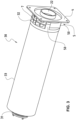
- FIG. 3 illustrates a cartridge 30 according to a preferred embodiment of the invention, according to which the body of the filter element 3 is cylindrical and the latter is connected to an exhaust cover 4 of square shape and at the periphery of the corners of which four Holes are provided for the insertion of fixing screws.
- the outlet orifice 22 is round to allow easy connection, for example to an outlet pipe.
- the cartridge 30 remains symmetrical with respect to the axis of the filter element 3 constituted by the inlet tip 31, the closing tip 32 and the intermediate filtering part 33.
- the exhaust are preferably chosen to correspond to the usual shape of the existing flanges and thus facilitate their pressing against a bearing surface of the pump 1 during assembly, as well as to facilitate the arrangement of the keying devices on its periphery. It will be understood, however, that it is also possible to envisage fixing lugs in the form of tabs projecting radially outwards, and which would be regularly spaced around circular arcs of the same length, or even other geometric shapes. adequate, preferably symmetrical.
- the exhaust cover 4 is arranged in a single piece with the closure end 32, such that the connection 5 here only constitutes a fictitious intrinsic part, because it is impossible to determine where this intermediate junction piece begins behind the closure end 32 and where it stops at the level of the cover.
- this intermediate space the guide surfaces 50 in the extension of the cylinder.
- the material used to make the end of this cartridge 30 by molding can consist for example of polyamide or polypropylene, or any suitable material capable of supporting a flow of air circulating around 80°C.
- a conductive material such as for example polypropylene with insertion of steel-stainless steel fibers, in order to be able to reduce the level of static electricity as much as possible.
- This preferred embodiment illustrated by the Figure 3 for the noise attenuator 7 also presents two technical advantages: the first consists of achieving the anti-noise attenuation function at the output without any part requiring an additional dedicated volume having to be provided specifically for this purpose, thus reducing clutter, and the second being, in the case where the grid is designed in a modular manner with respect to the connection 5 and the baffle 6, to simplify its manufacturing process as well as to make its replacement independent of that of the parts in which it is intended to be inserted.
- Such a keying system makes it possible to correctly orient the baffle 6 to the inside the housing 2 so that the roof - constituted here by the side spoilers 61 clearly visible on the figure 4D , and which are an integral part of it - allowing the drops of oil formed by gravity to be retained at the outlet of the exhaust filter to be correctly oriented.
- Other keying systems could also be envisaged, for example using a bayonet fixing, or with another number of screws and other geometric shapes for the exhaust cover 4; nevertheless, this variant proposed using pairs of holes and separate screws has the advantage of particularly simple implementation.
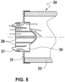
- the air enters the interior of the filter element 3 through a circular ring 37 and a series of holes 38 in such a way that the air flow passing through the circular ring 37 is relaxed quickly thanks to the widening 39.
- This air flow then joins the air passing through the holes 38 in a tangential manner, placing it on the conical surface also shown in the Figure 5 .
- This arrangement makes it possible to have the same noise damping as using the mobile valve 9 while allowing the assembly to be produced in a single, easy-to-machine part. Reliability is also improved since we only have static parts in the filter element 3.
- the integrated handle 8 has a particular shape, here in the shape of a “U” not interfering on the one hand with the extension of the orifice (that is to say, according to the embodiment, the second orifice of outlet 22 of said exhaust cover 4) so as not to disturb the flow of fluid during usual operating mode of the vacuum pump 1.
- a “U” shape also allows a particularly easy and intuitive grip for the user, like a drawer: all you need to do is insert your fingers into the outlet orifice 22 and then pull the exhaust cover 4 towards you.
- the integrated handle 8 is also arranged in a single piece, that is to say in one piece with the closing end 32 and the exhaust cover 4. It is thus part integral part of a fictitious junction part between these two elements and as such, it can be considered that the integrated handle 8 is also preferably arranged in a single piece with the connector 5, which makes it possible to simplify the machining process. .
- the preferred embodiment illustrated refers to a monobloc type structure for the cartridge 30 proposed in the context of the present invention
- constituents of this cartridge 30 relating to the different technical functions that they fulfill without departing from the scope of the invention. It is in particular possible to produce all the parts of the cartridge 30 independently and to provide adequate fixing means to allow their assembly.
- a cartridge 30 composed of such “spare parts” and these “spare parts” for the cartridge 30 also form part of the present invention at the same level as the cartridge 30 produced in a single piece.
- other geometric shapes, preferably symmetrical, are also possible for the exhaust cover and the filter element.
Landscapes
- Engineering & Computer Science (AREA)
- Mechanical Engineering (AREA)
- General Engineering & Computer Science (AREA)
- Chemical & Material Sciences (AREA)
- Chemical Kinetics & Catalysis (AREA)
- Physics & Mathematics (AREA)
- Geometry (AREA)
- Compressor (AREA)
- Applications Or Details Of Rotary Compressors (AREA)
- Jet Pumps And Other Pumps (AREA)
- Compressors, Vaccum Pumps And Other Relevant Systems (AREA)
- Filtering Of Dispersed Particles In Gases (AREA)
Claims (15)
- Vakuumpumpe (1), umfassend ein Gehäuse (2), in welchem eine erste Einlassöffnung (21) und eine zweite Auslassöffnung (22) vorgesehen sind, um ein Durchstrom eines Luftstroms (F) zu ermöglichen, und in dessen Innerem ein entfernbar montiertes Filterelement (3) vorgesehen ist, wobei das Filterelement (3) einen Verschlussstutzen (32) umfasst,
dadurch gekennzeichnet, dass mindestens eine Öffnung des Gehäuses (2), ausgewählt aus der ersten Einlassöffnung (21) und der zweiten Auslassöffnung (22), an einer Absaugabdeckung (4) angeordnet ist, wobei gleichzeitig die Absaugabdeckung (4) von dem Gehäuse (2) entfernbar ist, aber entweder als ein Stück gefertigt ist mit oder an dem Verschlussstutzen (32) des Filterelements (3) mittels Befestigungsmitteln befestigt ist. - Vakuumpumpe (1) nach Anspruch 1, dadurch gekennzeichnet, dass das Filterelement (3) ferner einen Einlassstutzen (31) umfasst, wobei der Einlassstutzen (31) und der Verschlussstutzen (32) zu beiden Seiten eines Zwischenfilterteils (33) angeordnet sind, wobei die Absaugabdeckung (4) mittels eines Verbindungsstücks (5) an dem Verschlussstutzen (32) befestigt ist.
- Vakuumpumpe (1) nach Anspruch 2, dadurch gekennzeichnet, dass ein Leitblech (6) an dem Verbindungsstück (5) oder der Absaugabdeckung (4) angeordnet ist.
- Vakuumpumpe (1) nach Anspruch 3, dadurch gekennzeichnet, dass ein Geräuschdämpfer (7) zwischen dem Verschlussstutzen (32) und der Öffnung des Gehäuses (2) angeordnet ist.
- Vakuumpumpe (1) nach einem der Ansprüche 3 oder 4, dadurch gekennzeichnet, dass die Absaugabdeckung (4) mit einem Ausrichtsystem versehen ist, um das Leitblech (6) korrekt auszurichten.
- Vakuumpumpe (1) nach Anspruch 5, dadurch gekennzeichnet, dass die Absaugabdeckung (4) mittels zweier Schraubenpaare mit dem Gehäuse (2) verschraubt ist, die jeweils in erste Schraubenlöcher (41) und zweite Schraubenlöcher (42) der Absaugabdeckung (4) eingesetzt sind, wobei die ersten Löcher (41) und die zweiten Löcher (42) jeweilige unterschiedliche Achsabstände haben.
- Vakuumpumpe (1) nach einem der Ansprüche 2 bis 6, dadurch gekennzeichnet, dass die Absaugabdeckung (4) und das Verbindungsstück (5) als ein Stück mit dem Verschlussstutzen (32) und dem Filterelement (3) gestaltet sind.
- Vakuumpumpe (1) nach einem der Ansprüche 1 bis 6, dadurch gekennzeichnet, dass ein Griff (8) an der Rückseite der Absaugabdeckung (4) integriert ist.
- Vakuumpumpe (1) nach Anspruch 8, dadurch gekennzeichnet, dass der Griff (8) eine "U"-Form aufweist, welche die erste Einlassöffnung (21) und die zweite Auslassöffnung (22) der Absaugabdeckung (4) nicht behindert.
- Vakuumpumpe (1) nach einem der Ansprüche 1 bis 7, dadurch gekennzeichnet, dass der Zusammenbau Filterelement (3) - Verbindungsstück (5) - Absaugabdeckung (4) eine Kartusche (30) mit einer Symmetrieachse (A-A) bildet, wobei der Einlassstutzen (31) auf der Höhe der ersten Einlassöffnung (21) befestigt ist und die Symmetrieachse (A-A) mit dem Abschnitt zusammenfällt, der das erste Zentrum (210) der ersten Einlassöffnung (21) und das zweite Zentrum (220) der zweiten Auslassöffnung (22) verbindet.
- Vakuumpumpe nach Anspruch 10, dadurch gekennzeichnet, dass Führungsflächen (50) in der Richtung der Symmetrieachse (A-A) in der Verlängerung der geometrischen Form des Filterelements (3) der Kartusche (30) vorgesehen sind.
- Kartusche (30) für eine Vakuumpumpe (1) nach einem der vorhergehenden Ansprüche 1 bis 11, dadurch gekennzeichnet, dass die Vakuumpumpe (1) ein Gehäuse (2) umfasst, in dessen Innerem ein in einer entfernbaren Weise montiertes Filterelement (3) vorgesehen ist, wobei die das Filterelement (3) enthaltende Kartusche (30) mit einem Verschlussstutzen (32) versehen ist, und die Kartusche (30) eine Absaugabdeckung (4) umfasst, entweder einstückig ausgebildet oder an dem Verschlussstutzen (32) des Filterelements (3) mittels Befestigungsmitteln befestigt.
- Kartusche (30) für eine Vakuumpumpe (1) nach Anspruch 12, dadurch gekennzeichnet, dass die Kartusche (30) weiter ein Einlassstutzen (31) umfasst, wobei der Einlassstutzen (31) und der Verschlussstutzen (32) zu beiden Seiten eines Zwischenfilterteils (33) angeordnet sind.
- Kartusche (30) für eine Vakuumpumpe (1) nach Anspruch 12 oder 13, dadurch gekennzeichnet, dass die Absaugabdeckung (4) weiter einen integrierten Griff (8) umfasst.
- Kartusche (30) für eine Vakuumpumpe (1) nach einem der vorhergehenden Ansprüche 12 bis 14, dadurch gekennzeichnet, dass ein Verbindungsstück (5), der den Verschlussstutzen (32) mit der Absaugabdeckung(4) verbindet und additional ein Leitblech (6) umfasst sind.
Applications Claiming Priority (3)
| Application Number | Priority Date | Filing Date | Title |
|---|---|---|---|
| PCT/EP2015/078226 WO2017092795A1 (fr) | 2015-12-01 | 2015-12-01 | Pompe a vide avec element filtrant |
| EP16812913.8A EP3384161B1 (de) | 2015-12-01 | 2016-12-01 | Vakuumpumpe mit filterelement |
| PCT/EP2016/079509 WO2017093441A1 (fr) | 2015-12-01 | 2016-12-01 | Pompe a vide avec element filtrant |
Related Parent Applications (1)
| Application Number | Title | Priority Date | Filing Date |
|---|---|---|---|
| EP16812913.8A Division EP3384161B1 (de) | 2015-12-01 | 2016-12-01 | Vakuumpumpe mit filterelement |
Publications (3)
| Publication Number | Publication Date |
|---|---|
| EP3663585A1 EP3663585A1 (de) | 2020-06-10 |
| EP3663585C0 EP3663585C0 (de) | 2024-01-10 |
| EP3663585B1 true EP3663585B1 (de) | 2024-01-10 |
Family
ID=54782696
Family Applications (2)
| Application Number | Title | Priority Date | Filing Date |
|---|---|---|---|
| EP20155484.7A Active EP3663585B1 (de) | 2015-12-01 | 2016-12-01 | Vakuumpumpe mit filterelement |
| EP16812913.8A Active EP3384161B1 (de) | 2015-12-01 | 2016-12-01 | Vakuumpumpe mit filterelement |
Family Applications After (1)
| Application Number | Title | Priority Date | Filing Date |
|---|---|---|---|
| EP16812913.8A Active EP3384161B1 (de) | 2015-12-01 | 2016-12-01 | Vakuumpumpe mit filterelement |
Country Status (15)
| Country | Link |
|---|---|
| US (1) | US11319958B2 (de) |
| EP (2) | EP3663585B1 (de) |
| JP (1) | JP7097295B2 (de) |
| KR (2) | KR102894825B1 (de) |
| CN (2) | CN108291548B (de) |
| AU (2) | AU2016363589B2 (de) |
| BR (1) | BR112018010604B1 (de) |
| CA (1) | CA3006628C (de) |
| DK (1) | DK3384161T3 (de) |
| ES (2) | ES2971224T3 (de) |
| PL (2) | PL3663585T3 (de) |
| PT (1) | PT3384161T (de) |
| RU (1) | RU2730191C2 (de) |
| TW (2) | TWI764271B (de) |
| WO (2) | WO2017092795A1 (de) |
Families Citing this family (12)
| Publication number | Priority date | Publication date | Assignee | Title |
|---|---|---|---|---|
| EP3525908B1 (de) * | 2016-10-13 | 2022-09-07 | Cobham Mission Systems Davenport LSS Inc. | Verbesserte wassertrennung für ein system mit verwendung eines psa-verfahrens |
| DE102019105695A1 (de) * | 2019-03-06 | 2020-09-10 | Gebr. Becker Gmbh | Ölgeschmierte Drehschieber-Vakuumpumpe |
| US11857900B2 (en) * | 2019-12-02 | 2024-01-02 | Porvair Filtration Group Limited | Gas filtration apparatus |
| CN113929179A (zh) * | 2020-06-29 | 2022-01-14 | 浙江绍兴苏泊尔生活电器有限公司 | 用于净水机的泵组件、安装座组件、增压装置和净水机 |
| KR102493792B1 (ko) * | 2020-12-01 | 2023-01-31 | 주식회사 마이크로필터 | 정수필터 어셈블리 및 이를 포함하는 냉장고 |
| GB2603971A (en) * | 2021-02-19 | 2022-08-24 | Leybold Tianjin Int Trade Co Ltd | Filtering module for use with a vacuum pump |
| US12510077B2 (en) * | 2021-07-08 | 2025-12-30 | Industrial Vacuum Transfer Services Usa, Llc | Air compressor having vacuum and associated methods for loading and extracting materials |
| US12485459B2 (en) | 2021-07-08 | 2025-12-02 | Industrial Vacuum Transfer Services Usa, Llc | Systems, assemblies, and methods for pyrophoric material extraction |
| CN114504889A (zh) * | 2022-02-22 | 2022-05-17 | 阜宁裕隆环保材料有限公司 | 一种带有快捷安装结构的除尘器用除尘滤袋 |
| USD989226S1 (en) * | 2022-07-01 | 2023-06-13 | Brio Water Technology, Inc. | Filter |
| USD990620S1 (en) * | 2022-07-01 | 2023-06-27 | Brio Water Technology, Inc. | Filter |
| CN118273927B (zh) * | 2024-05-31 | 2024-09-24 | 山西辉能科技有限公司 | 一种真空泵前过滤器 |
Family Cites Families (53)
| Publication number | Priority date | Publication date | Assignee | Title |
|---|---|---|---|---|
| US1769153A (en) * | 1928-03-07 | 1930-07-01 | Meyer William Warren | Rotary blower or pump |
| JPS5029162B1 (de) * | 1970-03-30 | 1975-09-20 | ||
| FR2255933A1 (en) * | 1973-12-27 | 1975-07-25 | Sofep | Disposable monobloc air filter assembly for automobiles - in which the lid and filter element with baseplate are single rigid unit formed by fusion welding |
| DE2915730C2 (de) * | 1979-04-19 | 1987-04-23 | Kronsbein, Dirk-Gustav, 4000 Düsseldorf | Patronenfilter |
| US4260402A (en) * | 1979-05-17 | 1981-04-07 | Ingersoll-Rand Company | Housing means for defining air/oil separator and oil reservoir assembly |
| SU1687883A1 (ru) * | 1988-11-29 | 1991-10-30 | Научно-Исследовательский Институт Прикладной Физики Ташкентского Государственного Университета Им.В.И.Ленина | Способ получени вакуума |
| DE4135442C1 (de) * | 1991-10-23 | 1993-04-01 | Mannesmann Ag, 4000 Duesseldorf, De | |
| JP3928816B2 (ja) * | 1996-12-03 | 2007-06-13 | 株式会社日立製作所 | 圧縮機 |
| ATE209751T1 (de) * | 1997-08-26 | 2001-12-15 | Crt Common Rail Tech Ag | Spiralverdrängermaschine für kompressible medien |
| EP1418337B1 (de) * | 1997-08-29 | 2007-12-19 | Denso Corporation | Spiralverdichter |
| JP2000153119A (ja) | 1998-11-17 | 2000-06-06 | Babcock Hitachi Kk | フィルタ装置 |
| DE19910744A1 (de) | 1999-03-11 | 2000-09-21 | Krantz Tkt Gmbh | Vorrichtung zur Filtration eines mit Aerosolen beladenen Gasstromes |
| JP2003034732A (ja) * | 2001-07-24 | 2003-02-07 | Toray Ind Inc | ポリブチレンテレフタレート樹脂発泡成形品 |
| GB2414424B (en) | 2002-06-07 | 2006-06-14 | Baldwin Filters Inc | Housing for environmentally friendly filter cartridge |
| GB2389323B (en) * | 2002-06-07 | 2005-08-17 | Baldwin Filters Inc | Environmentally friendly filter cartridge |
| US7014761B2 (en) * | 2002-06-07 | 2006-03-21 | Baldwin Filters, Inc. | Environmentally friendly dual lube venturi filter cartridge |
| US6833023B1 (en) * | 2003-02-14 | 2004-12-21 | International Liner Co., Inc. | Air filter assembly |
| ES2282775T3 (es) * | 2003-11-07 | 2007-10-16 | Gambro Lundia Ab | Conjunto de tapon terminal con manguera de bomba para un filtro y fil tro que comprende dicho conjunto de tapon terminal. |
| GB0417458D0 (en) * | 2004-08-05 | 2004-09-08 | Domnick Hunter Ltd | Filter assembly |
| GB0417462D0 (en) * | 2004-08-05 | 2004-09-08 | Domnick Hunter Ltd | Filter element |
| GB0417464D0 (en) * | 2004-08-05 | 2004-09-08 | Domnick Hunter Ltd | Filter assembly |
| US7291195B2 (en) * | 2005-11-23 | 2007-11-06 | Emerson Electric Co. | Durable filter cage for air-moving system |
| ES2676094T3 (es) * | 2006-06-21 | 2018-07-16 | Donaldson Filtration Deutschland Gmbh | Filtro con pieza de inserción reemplazable |
| WO2008064713A1 (fr) * | 2006-11-27 | 2008-06-05 | Ateliers Busch Sa | Dispositif de montage de filtres |
| USD583389S1 (en) * | 2007-04-26 | 2008-12-23 | Ateliers Busch Sa | Exhaust filter for a vacuum pump |
| GB2449846A (en) * | 2007-05-29 | 2008-12-10 | Psi Global Ltd | A coalescing filter |
| US8404029B2 (en) * | 2007-06-14 | 2013-03-26 | Donaldson Company, Inc. | Crankcase ventilation filter arrangments; components; and, methods |
| DE202008004288U1 (de) * | 2008-03-27 | 2009-08-06 | Mann+Hummel Gmbh | Filter |
| US8167966B2 (en) * | 2008-04-07 | 2012-05-01 | Cummins Filtration Ip, Inc. | Replaceable filter cartridge with removal feature |
| CN201218210Y (zh) * | 2008-05-28 | 2009-04-08 | 佛山市广顺电器有限公司 | 压缩机的进气装置 |
| CN201218200Y (zh) * | 2008-05-30 | 2009-04-08 | 上海通用汽车有限公司 | 一种可变排量的内啮合转子泵 |
| US8361181B2 (en) * | 2008-06-06 | 2013-01-29 | Donaldson Company, Inc. | Air cleaner assemblies; filter cartridges therefor; features; and, methods |
| JP5222054B2 (ja) * | 2008-07-23 | 2013-06-26 | Ckd株式会社 | 真空ユニット |
| US8268031B2 (en) * | 2008-09-11 | 2012-09-18 | Alstom Technology Ltd | Fabric filter system |
| ITRE20110078A1 (it) * | 2011-10-05 | 2013-04-06 | Ufi Filters Spa | Elemento collettore per una cartuccia filtrante |
| JP5804897B2 (ja) | 2011-10-28 | 2015-11-04 | ホーコス株式会社 | 集塵機用フィルタ装置、集塵機、フィルタ交換方法 |
| CN102889212B (zh) * | 2012-10-30 | 2015-08-12 | 南通金坤机械设备有限公司 | 旋片高效节能环保真空泵 |
| JP6377142B2 (ja) * | 2013-05-22 | 2018-08-22 | ドナルドソン カンパニー,インコーポレイティド | フィルタエレメント及びエアクリーナ |
| GB2520770A (en) * | 2013-12-02 | 2015-06-03 | Nano Porous Solutions Ltd | An end cap for a filter assembly |
| US10046263B2 (en) * | 2014-04-04 | 2018-08-14 | Cummins Filtration Ip, Inc. | Snap in place natural gas filter |
| CN204193737U (zh) * | 2014-10-20 | 2015-03-11 | 云南钛业股份有限公司 | 一种真空系统酸性气体除尘器 |
| KR102445292B1 (ko) * | 2014-12-10 | 2022-09-20 | 유에프아이 필터즈 소시에떼 퍼 아찌오니 | 내연 기관의 공기 흡인 인테이크로 향하는 공기의 필터 그룹 |
| CN104481878B (zh) * | 2014-12-12 | 2016-07-06 | 南通诺博特机器人制造有限公司 | 适用于砖瓦真空挤出的滑阀式真空泵 |
| DE102015014113A1 (de) * | 2015-11-04 | 2017-05-04 | Mann+Hummel Gmbh | Filterelement und Filteranordnung |
| ITUB20156823A1 (it) * | 2015-12-11 | 2017-06-11 | Ufi Filters Spa | Cartuccia filtrante aria con struttura interna |
| WO2018008132A1 (ja) * | 2016-07-07 | 2018-01-11 | 株式会社日立産機システム | スクロール式流体機械 |
| DE112016007225T5 (de) * | 2016-09-15 | 2019-06-13 | Mahle International Gmbh | Luftfilter |
| DE102016012327A1 (de) * | 2016-10-17 | 2018-04-19 | Mann + Hummel Gmbh | Rundfilterelement, insbesondere zur Gasfiltration |
| DE102016012325A1 (de) * | 2016-10-17 | 2018-04-19 | Mann + Hummel Gmbh | Rundfilterelement, insbesondere zur Gasfiltration |
| US11724220B2 (en) * | 2017-02-21 | 2023-08-15 | Cummins Filtration Ip, Inc. | Undulated interlocking housing-endplate interface geometry |
| DE102018000538A1 (de) * | 2018-01-24 | 2019-07-25 | Mann+Hummel Gmbh | Filtergehäuse für eine Filtereinrichtung |
| US11331610B2 (en) * | 2018-12-21 | 2022-05-17 | Ingersoll-Rand Industrial U.S., Inc. | Filter system and replaceable filter cartridge |
| US11136948B2 (en) * | 2019-03-13 | 2021-10-05 | Mann+Hummel Gmbh | Multi-modal multi-media air filtration system |
-
2015
- 2015-12-01 WO PCT/EP2015/078226 patent/WO2017092795A1/fr not_active Ceased
-
2016
- 2016-12-01 AU AU2016363589A patent/AU2016363589B2/en active Active
- 2016-12-01 US US15/777,717 patent/US11319958B2/en active Active
- 2016-12-01 PL PL20155484.7T patent/PL3663585T3/pl unknown
- 2016-12-01 ES ES20155484T patent/ES2971224T3/es active Active
- 2016-12-01 KR KR1020247012814A patent/KR102894825B1/ko active Active
- 2016-12-01 WO PCT/EP2016/079509 patent/WO2017093441A1/fr not_active Ceased
- 2016-12-01 PT PT168129138T patent/PT3384161T/pt unknown
- 2016-12-01 ES ES16812913T patent/ES2775705T3/es active Active
- 2016-12-01 TW TW109130977A patent/TWI764271B/zh active
- 2016-12-01 EP EP20155484.7A patent/EP3663585B1/de active Active
- 2016-12-01 PL PL16812913T patent/PL3384161T3/pl unknown
- 2016-12-01 DK DK16812913.8T patent/DK3384161T3/da active
- 2016-12-01 TW TW105139707A patent/TWI708015B/zh active
- 2016-12-01 BR BR112018010604-6A patent/BR112018010604B1/pt active IP Right Grant
- 2016-12-01 JP JP2018527929A patent/JP7097295B2/ja active Active
- 2016-12-01 EP EP16812913.8A patent/EP3384161B1/de active Active
- 2016-12-01 KR KR1020187018871A patent/KR102659707B1/ko active Active
- 2016-12-01 CN CN201680070635.6A patent/CN108291548B/zh active Active
- 2016-12-01 CA CA3006628A patent/CA3006628C/fr active Active
- 2016-12-01 RU RU2018123175A patent/RU2730191C2/ru active
- 2016-12-01 CN CN202010668849.1A patent/CN111894853B/zh active Active
-
2020
- 2020-12-04 AU AU2020281134A patent/AU2020281134B2/en active Active
Also Published As
Similar Documents
| Publication | Publication Date | Title |
|---|---|---|
| EP3663585B1 (de) | Vakuumpumpe mit filterelement | |
| CA2946958C (fr) | Module de turbomachine comportant un carter autour d'un equipement avec un capot de recuperation d'huile de lubrification | |
| FR3019775A1 (de) | ||
| EP2717987B1 (de) | Flüssigkeitsfilter und maschinenbaugruppe als träger zur befestigung eines filtergehäuses | |
| CA2621837C (fr) | Systeme de deshuilage pour moteur d'aeronef | |
| FR2928705A1 (fr) | Dispositif d'attenuation acoustique pour ligne d'admission d'un moteur thermique,et ligne d'admission l'incorporant. | |
| EP1433948B1 (de) | Luftansaugdämpfungsanlage | |
| EP3303815A1 (de) | Vorrichtung zur dämpfung von ansauggeräuschen und abgestrahlten geräuschen | |
| CA2761601C (fr) | Turbomoteur comportant un cone de guidage des gaz d'echappement avec un attenuateur sonore | |
| FR3103527A1 (fr) | Elément de séparation de module hydraulique antivibratoire et module hydraulique antivibratoire équipé d’un tel élément de séparation | |
| FR2910529A3 (fr) | Systeme hydraulique pour le rattrapage de jeu des soupapes des moteurs a combustion interne | |
| FR3027973A1 (fr) | Carter de turbomachine, comprenant un dispositif de guidage de l'air en rotation dans le carter | |
| WO2020164876A1 (fr) | Sonde de reniflage et détecteur de fuites | |
| FR2946120A1 (fr) | Dispositif d'attenuation acoustique pour ligne d'admission d'un moteur thermique,et ligne d'admission l'incorporant. | |
| EP3233241B1 (de) | Vorrichtung zum abscheiden von öl | |
| FR3048462A1 (fr) | Pompe, notamment a palettes lubrifiees | |
| FR2903459A1 (fr) | Pompe a engrenages comportant un dispositif d'amortissement de pulsations d'aspiration de fluide hydraulique | |
| EP3206773B1 (de) | Kraftstofffiltersystem mit integrierter pumpe | |
| FR3154450A1 (fr) | Ensemble pour boitier d’accessoires de turbomachine | |
| FR2967917A1 (fr) | Filtre destine a une bouche d'aspiration d'un systeme confine d'un aeronef | |
| FR3154439A1 (fr) | Ensemble pour boitier d’accessoires de turbomachine | |
| FR2986976A1 (fr) | Cartouche de filtration integrant un element permeable au gaz dans le flasque superieur | |
| EP2428681A1 (de) | Umwälzpumpe | |
| FR3091897A1 (fr) | Circuit de refroidissement | |
| FR2899302A1 (fr) | Ensemble de distribution de fluide et utilisation correspondante. |
Legal Events
| Date | Code | Title | Description |
|---|---|---|---|
| PUAI | Public reference made under article 153(3) epc to a published international application that has entered the european phase |
Free format text: ORIGINAL CODE: 0009012 |
|
| STAA | Information on the status of an ep patent application or granted ep patent |
Free format text: STATUS: THE APPLICATION HAS BEEN PUBLISHED |
|
| AC | Divisional application: reference to earlier application |
Ref document number: 3384161 Country of ref document: EP Kind code of ref document: P |
|
| AK | Designated contracting states |
Kind code of ref document: A1 Designated state(s): AL AT BE BG CH CY CZ DE DK EE ES FI FR GB GR HR HU IE IS IT LI LT LU LV MC MK MT NL NO PL PT RO RS SE SI SK SM TR |
|
| STAA | Information on the status of an ep patent application or granted ep patent |
Free format text: STATUS: REQUEST FOR EXAMINATION WAS MADE |
|
| 17P | Request for examination filed |
Effective date: 20201116 |
|
| RBV | Designated contracting states (corrected) |
Designated state(s): AL AT BE BG CH CY CZ DE DK EE ES FI FR GB GR HR HU IE IS IT LI LT LU LV MC MK MT NL NO PL PT RO RS SE SI SK SM TR |
|
| STAA | Information on the status of an ep patent application or granted ep patent |
Free format text: STATUS: EXAMINATION IS IN PROGRESS |
|
| 17Q | First examination report despatched |
Effective date: 20210802 |
|
| GRAP | Despatch of communication of intention to grant a patent |
Free format text: ORIGINAL CODE: EPIDOSNIGR1 |
|
| STAA | Information on the status of an ep patent application or granted ep patent |
Free format text: STATUS: GRANT OF PATENT IS INTENDED |
|
| INTG | Intention to grant announced |
Effective date: 20230724 |
|
| GRAS | Grant fee paid |
Free format text: ORIGINAL CODE: EPIDOSNIGR3 |
|
| GRAA | (expected) grant |
Free format text: ORIGINAL CODE: 0009210 |
|
| STAA | Information on the status of an ep patent application or granted ep patent |
Free format text: STATUS: THE PATENT HAS BEEN GRANTED |
|
| AC | Divisional application: reference to earlier application |
Ref document number: 3384161 Country of ref document: EP Kind code of ref document: P |
|
| AK | Designated contracting states |
Kind code of ref document: B1 Designated state(s): AL AT BE BG CH CY CZ DE DK EE ES FI FR GB GR HR HU IE IS IT LI LT LU LV MC MK MT NL NO PL PT RO RS SE SI SK SM TR |
|
| REG | Reference to a national code |
Ref country code: GB Ref legal event code: FG4D Free format text: NOT ENGLISH |
|
| REG | Reference to a national code |
Ref country code: CH Ref legal event code: EP |
|
| REG | Reference to a national code |
Ref country code: DE Ref legal event code: R096 Ref document number: 602016085325 Country of ref document: DE |
|
| REG | Reference to a national code |
Ref country code: IE Ref legal event code: FG4D Free format text: LANGUAGE OF EP DOCUMENT: FRENCH |
|
| U01 | Request for unitary effect filed |
Effective date: 20240131 |
|
| U07 | Unitary effect registered |
Designated state(s): AT BE BG DE DK EE FI FR IT LT LU LV MT NL PT SE SI Effective date: 20240205 |
|
| REG | Reference to a national code |
Ref country code: ES Ref legal event code: FG2A Ref document number: 2971224 Country of ref document: ES Kind code of ref document: T3 Effective date: 20240604 |
|
| PG25 | Lapsed in a contracting state [announced via postgrant information from national office to epo] |
Ref country code: IS Free format text: LAPSE BECAUSE OF FAILURE TO SUBMIT A TRANSLATION OF THE DESCRIPTION OR TO PAY THE FEE WITHIN THE PRESCRIBED TIME-LIMIT Effective date: 20240510 |
|
| PG25 | Lapsed in a contracting state [announced via postgrant information from national office to epo] |
Ref country code: GR Free format text: LAPSE BECAUSE OF FAILURE TO SUBMIT A TRANSLATION OF THE DESCRIPTION OR TO PAY THE FEE WITHIN THE PRESCRIBED TIME-LIMIT Effective date: 20240411 |
|
| PG25 | Lapsed in a contracting state [announced via postgrant information from national office to epo] |
Ref country code: HR Free format text: LAPSE BECAUSE OF FAILURE TO SUBMIT A TRANSLATION OF THE DESCRIPTION OR TO PAY THE FEE WITHIN THE PRESCRIBED TIME-LIMIT Effective date: 20240110 Ref country code: RS Free format text: LAPSE BECAUSE OF FAILURE TO SUBMIT A TRANSLATION OF THE DESCRIPTION OR TO PAY THE FEE WITHIN THE PRESCRIBED TIME-LIMIT Effective date: 20240410 |
|
| PG25 | Lapsed in a contracting state [announced via postgrant information from national office to epo] |
Ref country code: RS Free format text: LAPSE BECAUSE OF FAILURE TO SUBMIT A TRANSLATION OF THE DESCRIPTION OR TO PAY THE FEE WITHIN THE PRESCRIBED TIME-LIMIT Effective date: 20240410 Ref country code: NO Free format text: LAPSE BECAUSE OF FAILURE TO SUBMIT A TRANSLATION OF THE DESCRIPTION OR TO PAY THE FEE WITHIN THE PRESCRIBED TIME-LIMIT Effective date: 20240410 Ref country code: IS Free format text: LAPSE BECAUSE OF FAILURE TO SUBMIT A TRANSLATION OF THE DESCRIPTION OR TO PAY THE FEE WITHIN THE PRESCRIBED TIME-LIMIT Effective date: 20240510 Ref country code: HR Free format text: LAPSE BECAUSE OF FAILURE TO SUBMIT A TRANSLATION OF THE DESCRIPTION OR TO PAY THE FEE WITHIN THE PRESCRIBED TIME-LIMIT Effective date: 20240110 Ref country code: GR Free format text: LAPSE BECAUSE OF FAILURE TO SUBMIT A TRANSLATION OF THE DESCRIPTION OR TO PAY THE FEE WITHIN THE PRESCRIBED TIME-LIMIT Effective date: 20240411 |
|
| REG | Reference to a national code |
Ref country code: DE Ref legal event code: R097 Ref document number: 602016085325 Country of ref document: DE |
|
| PG25 | Lapsed in a contracting state [announced via postgrant information from national office to epo] |
Ref country code: SM Free format text: LAPSE BECAUSE OF FAILURE TO SUBMIT A TRANSLATION OF THE DESCRIPTION OR TO PAY THE FEE WITHIN THE PRESCRIBED TIME-LIMIT Effective date: 20240110 |
|
| PG25 | Lapsed in a contracting state [announced via postgrant information from national office to epo] |
Ref country code: CZ Free format text: LAPSE BECAUSE OF FAILURE TO SUBMIT A TRANSLATION OF THE DESCRIPTION OR TO PAY THE FEE WITHIN THE PRESCRIBED TIME-LIMIT Effective date: 20240110 |
|
| PG25 | Lapsed in a contracting state [announced via postgrant information from national office to epo] |
Ref country code: SK Free format text: LAPSE BECAUSE OF FAILURE TO SUBMIT A TRANSLATION OF THE DESCRIPTION OR TO PAY THE FEE WITHIN THE PRESCRIBED TIME-LIMIT Effective date: 20240110 |
|
| PG25 | Lapsed in a contracting state [announced via postgrant information from national office to epo] |
Ref country code: SM Free format text: LAPSE BECAUSE OF FAILURE TO SUBMIT A TRANSLATION OF THE DESCRIPTION OR TO PAY THE FEE WITHIN THE PRESCRIBED TIME-LIMIT Effective date: 20240110 Ref country code: SK Free format text: LAPSE BECAUSE OF FAILURE TO SUBMIT A TRANSLATION OF THE DESCRIPTION OR TO PAY THE FEE WITHIN THE PRESCRIBED TIME-LIMIT Effective date: 20240110 Ref country code: RO Free format text: LAPSE BECAUSE OF FAILURE TO SUBMIT A TRANSLATION OF THE DESCRIPTION OR TO PAY THE FEE WITHIN THE PRESCRIBED TIME-LIMIT Effective date: 20240110 Ref country code: CZ Free format text: LAPSE BECAUSE OF FAILURE TO SUBMIT A TRANSLATION OF THE DESCRIPTION OR TO PAY THE FEE WITHIN THE PRESCRIBED TIME-LIMIT Effective date: 20240110 |
|
| PLBE | No opposition filed within time limit |
Free format text: ORIGINAL CODE: 0009261 |
|
| STAA | Information on the status of an ep patent application or granted ep patent |
Free format text: STATUS: NO OPPOSITION FILED WITHIN TIME LIMIT |
|
| 26N | No opposition filed |
Effective date: 20241011 |
|
| U20 | Renewal fee for the european patent with unitary effect paid |
Year of fee payment: 9 Effective date: 20241205 |
|
| PGFP | Annual fee paid to national office [announced via postgrant information from national office to epo] |
Ref country code: PL Payment date: 20241121 Year of fee payment: 9 |
|
| PGFP | Annual fee paid to national office [announced via postgrant information from national office to epo] |
Ref country code: IE Payment date: 20241223 Year of fee payment: 9 |
|
| PGFP | Annual fee paid to national office [announced via postgrant information from national office to epo] |
Ref country code: TR Payment date: 20241125 Year of fee payment: 9 |
|
| PGFP | Annual fee paid to national office [announced via postgrant information from national office to epo] |
Ref country code: ES Payment date: 20250131 Year of fee payment: 9 |
|
| PGFP | Annual fee paid to national office [announced via postgrant information from national office to epo] |
Ref country code: CH Payment date: 20250101 Year of fee payment: 9 |
|
| REG | Reference to a national code |
Ref country code: CH Ref legal event code: U11 Free format text: ST27 STATUS EVENT CODE: U-0-0-U10-U11 (AS PROVIDED BY THE NATIONAL OFFICE) Effective date: 20260101 |
|
| PGFP | Annual fee paid to national office [announced via postgrant information from national office to epo] |
Ref country code: GB Payment date: 20251219 Year of fee payment: 10 |
|
| PGFP | Annual fee paid to national office [announced via postgrant information from national office to epo] |
Ref country code: MC Payment date: 20251223 Year of fee payment: 10 |
|
| U20 | Renewal fee for the european patent with unitary effect paid |
Year of fee payment: 10 Effective date: 20251205 |