EP3663513A1 - Cutter head for mining machine - Google Patents
Cutter head for mining machine Download PDFInfo
- Publication number
- EP3663513A1 EP3663513A1 EP19218675.7A EP19218675A EP3663513A1 EP 3663513 A1 EP3663513 A1 EP 3663513A1 EP 19218675 A EP19218675 A EP 19218675A EP 3663513 A1 EP3663513 A1 EP 3663513A1
- Authority
- EP
- European Patent Office
- Prior art keywords
- cutter head
- cutting
- mass
- cutting bit
- rock
- Prior art date
- Legal status (The legal status is an assumption and is not a legal conclusion. Google has not performed a legal analysis and makes no representation as to the accuracy of the status listed.)
- Pending
Links
- 238000005065 mining Methods 0.000 title description 31
- 238000005520 cutting process Methods 0.000 claims abstract description 232
- 239000011435 rock Substances 0.000 claims description 78
- 238000000034 method Methods 0.000 claims description 41
- 239000000463 material Substances 0.000 claims description 6
- 239000012530 fluid Substances 0.000 description 30
- 230000010355 oscillation Effects 0.000 description 24
- 230000008878 coupling Effects 0.000 description 21
- 238000010168 coupling process Methods 0.000 description 21
- 238000005859 coupling reaction Methods 0.000 description 21
- 230000008859 change Effects 0.000 description 13
- 238000004891 communication Methods 0.000 description 10
- 230000033001 locomotion Effects 0.000 description 10
- 230000001965 increasing effect Effects 0.000 description 7
- 238000006243 chemical reaction Methods 0.000 description 3
- 230000005284 excitation Effects 0.000 description 3
- 230000009471 action Effects 0.000 description 2
- 230000008901 benefit Effects 0.000 description 2
- 238000010276 construction Methods 0.000 description 2
- 230000007423 decrease Effects 0.000 description 2
- 230000006872 improvement Effects 0.000 description 2
- 238000005259 measurement Methods 0.000 description 2
- 238000012986 modification Methods 0.000 description 2
- 230000004048 modification Effects 0.000 description 2
- 238000012544 monitoring process Methods 0.000 description 2
- 229920000049 Carbon (fiber) Polymers 0.000 description 1
- 230000003044 adaptive effect Effects 0.000 description 1
- 238000009412 basement excavation Methods 0.000 description 1
- 230000005540 biological transmission Effects 0.000 description 1
- 239000004917 carbon fiber Substances 0.000 description 1
- 239000002131 composite material Substances 0.000 description 1
- 238000007796 conventional method Methods 0.000 description 1
- 230000007812 deficiency Effects 0.000 description 1
- 238000013461 design Methods 0.000 description 1
- 238000011161 development Methods 0.000 description 1
- 230000000694 effects Effects 0.000 description 1
- 238000005265 energy consumption Methods 0.000 description 1
- 230000001939 inductive effect Effects 0.000 description 1
- 238000012423 maintenance Methods 0.000 description 1
- 238000004519 manufacturing process Methods 0.000 description 1
- VNWKTOKETHGBQD-UHFFFAOYSA-N methane Chemical compound C VNWKTOKETHGBQD-UHFFFAOYSA-N 0.000 description 1
- 239000002245 particle Substances 0.000 description 1
- 230000008569 process Effects 0.000 description 1
- 230000004044 response Effects 0.000 description 1
- 238000000926 separation method Methods 0.000 description 1
- 230000001360 synchronised effect Effects 0.000 description 1
- XLYOFNOQVPJJNP-UHFFFAOYSA-N water Substances O XLYOFNOQVPJJNP-UHFFFAOYSA-N 0.000 description 1
Images


Classifications
-
- E—FIXED CONSTRUCTIONS
- E21—EARTH DRILLING; MINING
- E21C—MINING OR QUARRYING
- E21C25/00—Cutting machines, i.e. for making slits approximately parallel or perpendicular to the seam
- E21C25/16—Machines slitting solely by one or more rotating saws, cutting discs, or wheels
-
- E—FIXED CONSTRUCTIONS
- E21—EARTH DRILLING; MINING
- E21C—MINING OR QUARRYING
- E21C27/00—Machines which completely free the mineral from the seam
- E21C27/10—Machines which completely free the mineral from the seam by both slitting and breaking-down
- E21C27/14—Machines which completely free the mineral from the seam by both slitting and breaking-down breaking-down effected by force or pressure applied to side of slit, e.g. by wedges
- E21C27/16—Machines which completely free the mineral from the seam by both slitting and breaking-down breaking-down effected by force or pressure applied to side of slit, e.g. by wedges with means for both slitting and breaking-down
-
- E—FIXED CONSTRUCTIONS
- E21—EARTH DRILLING; MINING
- E21C—MINING OR QUARRYING
- E21C25/00—Cutting machines, i.e. for making slits approximately parallel or perpendicular to the seam
- E21C25/06—Machines slitting solely by one or more cutting rods or cutting drums which rotate, move through the seam, and may or may not reciprocate
-
- E—FIXED CONSTRUCTIONS
- E21—EARTH DRILLING; MINING
- E21C—MINING OR QUARRYING
- E21C31/00—Driving means incorporated in machines for slitting or completely freeing the mineral from the seam
- E21C31/02—Driving means incorporated in machines for slitting or completely freeing the mineral from the seam for cutting or breaking-down devices
-
- E—FIXED CONSTRUCTIONS
- E21—EARTH DRILLING; MINING
- E21C—MINING OR QUARRYING
- E21C35/00—Details of, or accessories for, machines for slitting or completely freeing the mineral from the seam, not provided for in groups E21C25/00 - E21C33/00, E21C37/00 or E21C39/00
-
- E—FIXED CONSTRUCTIONS
- E21—EARTH DRILLING; MINING
- E21C—MINING OR QUARRYING
- E21C35/00—Details of, or accessories for, machines for slitting or completely freeing the mineral from the seam, not provided for in groups E21C25/00 - E21C33/00, E21C37/00 or E21C39/00
- E21C35/22—Equipment for preventing the formation of, or for removal of, dust
- E21C35/23—Distribution of spraying-fluids in rotating cutter-heads
-
- E—FIXED CONSTRUCTIONS
- E21—EARTH DRILLING; MINING
- E21C—MINING OR QUARRYING
- E21C35/00—Details of, or accessories for, machines for slitting or completely freeing the mineral from the seam, not provided for in groups E21C25/00 - E21C33/00, E21C37/00 or E21C39/00
- E21C35/24—Remote control specially adapted for machines for slitting or completely freeing the mineral
-
- E—FIXED CONSTRUCTIONS
- E21—EARTH DRILLING; MINING
- E21C—MINING OR QUARRYING
- E21C41/00—Methods of underground or surface mining; Layouts therefor
- E21C41/16—Methods of underground mining; Layouts therefor
-
- E—FIXED CONSTRUCTIONS
- E21—EARTH DRILLING; MINING
- E21D—SHAFTS; TUNNELS; GALLERIES; LARGE UNDERGROUND CHAMBERS
- E21D9/00—Tunnels or galleries, with or without linings; Methods or apparatus for making thereof; Layout of tunnels or galleries
- E21D9/10—Making by using boring or cutting machines
- E21D9/1006—Making by using boring or cutting machines with rotary cutting tools
- E21D9/1013—Making by using boring or cutting machines with rotary cutting tools on a tool-carrier supported by a movable boom
- E21D9/102—Making by using boring or cutting machines with rotary cutting tools on a tool-carrier supported by a movable boom by a longitudinally extending boom being pivotable about a vertical and a transverse axis
Definitions
- the present invention relates to underground mining machines, and in particular to a cutter head for an underground mining machine.
- a hard rock continuous miner includes a cutter head having an oscillating cutting disc.
- the oscillating disc cutter transmits all of the dynamic cutting forces through the bearings, and the life of the bearings are limited due to the high loads and high speed of the cutting discs.
- the oscillating discs require large face seal surface areas in the primary cutting area, while the cutting discs oscillate at frequencies typically around 50 Hz. It is difficult to seal a large area with a high surface velocity, and this is further complicated due to the fact that the cutting operation generates a large amount of highly abrasive rock particles. The combination of the contaminated environment and high surface velocity accelerates wear on the seals and decreases the working life of the seals.
- the deficiencies in the seals and the highly loaded bearings can combine to even further increase maintenance and replacement of the disc cutter assembly. These factors also limit the frequency and the eccentricity of oscillation of the cutting discs, thereby limiting the total power available for rock cutting
- oscillating disc cutter systems typically lack a means for directly monitoring the behavior of the disc cutter at the cutting surface.
- it is difficult to sense a change in the cutting conditions (e.g., when the hardness of the rock changes).
- the operator is unable to control the disc cutter to optimize the cutting performance.
- the invention provides a cutter head for a mining machine including a frame and a boom movably coupled to the frame.
- the cutter head includes a first member, a cutting bit, and a second member.
- the first member includes a first end and a second end and includes a first mass.
- the cutting bit is coupled to the first member proximate the second end and includes a cutting edge.
- the second member is rotatable about an axis and includes a second mass eccentrically positioned with respect to the axis.
- the second mass and the first mass at least partially define a combined center of mass. Rotation of the second mass causes the first member and the cutting bit to oscillate about the combined center of mass along a closed path.
- the invention provides a mining machine including a frame for supporting the machine on a support surface, a boom, and a cutter head.
- the boom includes a first end coupled to the frame and a second end positioned away from the frame.
- the cutter head a cutter head coupled to the second end of the boom, the cutter head includes a first member, a cutting bit, and a second member.
- the first member defines a first end and a second end and includes a first mass and a coupling member supporting the first mass on the second end of the boom.
- the cutting bit is coupled to the first member proximate the second end and includes a cutting edge. The first member and the cutting bit at least partially define a first mass center.
- the second member is rotatable about an axis and includes a second mass eccentrically positioned with respect to the axis.
- the second mass defines a second mass center.
- the first mass center and the second mass center define a combined center of mass. Rotation of the second mass about the axis causing the first member and the cutting bit to oscillate about the combined center of mass along a closed path.
- the invention provides a mining machine including a frame for supporting the machine on a support surface, a boom, a cutter head, and a coupling member.
- the boom includes a first end coupled to the frame and a second end positioned away from the frame; the second end includes a bracket.
- the cutter head includes a first member and a cutting bit.
- the first member includes a first end coupled to the bracket and a second end.
- the cutting bit is coupled to the first member proximate the second end.
- the coupling member supporting the first member on the second end of the boom to facilitate oscillation of the cutter head relative to the boom.
- the invention provides a cutter head for a mining machine including a frame and a boom movably coupled to the frame.
- the cutter head includes a first member, a cutting bit, a fluid conduit, and a plurality of nozzles.
- the first member includes a first end and a second end and is movable relative to the second end.
- the cutting bit is coupled to the first member proximate the second end.
- the fluid conduit extends through the first member and is configured to be in fluid communication with a fluid source.
- the nozzles are positioned on the cutting edge, the nozzles in fluid communication with the fluid conduit.
- the invention provides a method for removing material from a rock wall.
- the method includes moving a cutting edge through the rock wall to create a first slot in the rock wall; moving the cutting edge through the rock wall to create a second slot in the rock wall, the second slot being separated from the first slot by an uncut portion, the uncut portion defining a base surface attached to the wall; cutting a notch into the base surface of the uncut portion; and applying a force on the uncut portion to break the uncut portion away from the wall.
- the invention provides a method for controlling a mining machine.
- the method includes sensing a value of an indicator of a cutting efficiency of a cutter head; comparing the sensed value with a desired value; modifying an operating parameter in a first direction from an initial value to a second value; detecting the change in the indicator of cutting efficiency; and when the change in the indicator of the cutting efficiency represents an improvement, modifying the operating parameter further in the first direction to a third value.
- the invention provides a method for controlling a mining machine.
- the method includes sensing a first value of an indicator of a cutting efficiency of a first cutter; sensing a second value of an indicator of cutting efficiency of a second cutter; comparing the first value with the second value to detect whether the first value is less than the second value; when the first value is less than the second value, modifying an operating parameter of the second cutter so that the second value matches the first value.
- a cutter head for a mining machine mining machine including a frame and a boom movably coupled to the frame, the cutter head comprising: a first member including a first end and a second end and including a first mass; a cutting bit coupled to the first member proximate the second end, the cutting bit including a cutting edge; and a second member rotatable about an axis and including a second mass eccentrically positioned with respect to the axis, the second mass and the first mass at least partially defining a combined center of mass, rotation of the second mass causing the first member and the cutting bit to oscillate about the combined center of mass along a closed path.
- the first member may include a coupling member adapted to support the first member relative to an end of the boom.
- the coupling member may include a resilient member permitting oscillation of the cutter head relative to an end of the boom.
- the coupling member may include a ball joint permitting oscillation of the cutter head relative to an end of the boom.
- the second mass may oscillate about the combined center of mass at an effective radius, wherein a dimension of the closed path is proportional to the mass of the second member and the effective radius.
- the first member may define a first mass center and the second member may define a second mass center, the first mass center and the second mass center define the combined center of mass, wherein the first mass center moves in an orbital manner about the combined center of mass and the second mass center moves in an orbital manner about the combined center of mass.
- a reference line extends from the cutting bit to the first end of the first member, and wherein the oscillation of the first member and the cutting bit may move the reference line and cause the reference line to trace a conical shape having a circular base, the closed path being coextensive with the base, an apex of the cone being positioned at the first end of the first member.
- the first member may have a tapered shape such that the first end is wider than the second end.
- the cutter head may further comprise a motor driving the second member about the axis, wherein the center of mass is also defined by the motor and the second member.
- the motor may be a first motor and the cutter head may further comprise a second motor for rotating the first member.
- the second member may include a first lobe movable about the axis and a second lobe movable about the axis, the second lobe being movable about the axis relative to the first lobe.
- the first lobe may rotate about the axis in a first direction and the second lobe may rotate about the axis in a second direction opposite the first direction.
- the cutter head may further comprise a first motor and a second motor, wherein the first lobe is coupled to a first shaft driven by the first motor, and the second lobe is coupled to a second shaft driven by the second motor.
- the second member may include a shaft coupled to the second mass for rotation about the axis, the shaft including a first fluid conduit extending through the shaft, and wherein the cutting bit further includes a second fluid conduit in fluid communication with the first fluid conduit, the second fluid conduit extending radially through the cutting bit.
- the cutting bit may include a ring, a plurality of cutting tips positioned around a perimeter of the ring, and a plurality of nozzles in fluid communication with the second fluid conduit.
- Each nozzle may be positioned between adjacent cutting tips.
- the cutting bit may be rotatable relative to the first member.
- a mining machine comprises: a frame for supporting the machine on a support surface; a boom including a first end coupled to the frame and a second end positioned away from the frame; and a cutter head coupled to the second end of the boom, the cutter head including a first member defining a first end and a second end and including a first mass and a coupling member supporting the first mass on the second end of the boom, a cutting bit coupled to the first member proximate the second end and including a cutting edge, the first member and the cutting bit at least partially defining a first mass center; and a second member rotatable about an axis and including a second mass eccentrically positioned with respect to the axis, the second mass defining a second mass center, the first mass center and the second mass center defining a combined center of mass, rotation of the second mass about the axis causing the first member and the cutting bit to oscillate about the combined center of mass along a closed path.
- the coupling member may include a resilient member permitting oscillation of the cutter head relative to the second end of the boom.
- the resilient member may include at least one pin and a spring, the pin extending between the first end of the first member and the second end of the boom, the spring positioned around the pin to exert a spring force on the first member.
- the resilient member may include at least one hydraulic cylinder positioned between the first end of the first member and the second end of the boom, each cylinder being extendable and retractable to change an angle of the cutter head relative to the boom.
- the coupling member may include a ball joint permitting the first member to oscillate relative to the second end of the boom.
- the dimension of the closed path may be proportional to the mass of the second member and the eccentricity of the second mass.
- a reference line extends from the cutting bit to the first end of the first member, and wherein the oscillation of the first member and the cutting bit may move the reference line, causing the reference line to trace a conical shape having a circular base generally corresponding to the closed path.
- the first mass center may move in an orbital manner about the combined center of mass and the second mass center moves in an orbital manner about the combined center of mass.
- a reference line extends from the cutting bit to the first end of the first member, and wherein the oscillation of the first member and the cutting bit may move the reference line and causes the reference line to trace a conical shape having a circular base, the closed path being coextensive with the base, an apex of the cone being positioned at the first end of the first member.
- the first member may have a tapered shape such that the first end is wider than the second end.
- the cutter head may further include a motor driving the second member about the axis.
- the motor may be a first motor and the cutter head may further include a second motor for rotating the first member.
- the second mass may include a first lobe and a second lobe, the second lobe being movable about the axis relative to the first lobe.
- the first lobe may rotate about the axis in a first direction and the second lobe may rotate about the axis in a second direction opposite the first direction.
- the cutter head may further include a first motor and a second motor, wherein the first lobe is coupled to a first shaft driven by the first motor, and the second lobe is coupled to a second shaft driven by the second motor.
- a mining machine comprises: a frame for supporting the machine on a support surface; a boom including a first end coupled to the frame and a second end positioned away from the frame; a cutter head including a first member and a cutting bit, the first member including a first end coupled to the bracket and a second end, the cutting bit coupled to the first member proximate the second end; and a coupling member supporting the first member on the second end of the boom to facilitate oscillation of the cutter head relative to the boom.
- the cutter head may further include an eccentric member rotatable about an axis of rotation that generally extends between the first end and the second end, rotation of the eccentric member inducing the first member and the cutting bit to oscillate relative to the resilient member about a center of mass.
- the coupling member may include at least one spring and a pin extending through the spring and between the first end of the first member and the bracket, the spring exerting a spring force on the first member to bias the first member against a reaction force exerted on the cutting bit.
- the coupling member may include at least one hydraulic cylinder positioned between the first end of the first member and the bracket, the cylinder being extendable and retractable to change an orientation of the cutter head relative to the boom.
- the coupling member may include at least one hydraulic cylinder positioned between the first end of the first member and the bracket, the cylinder being extendable and retractable to modify an oscillation of the first member and the cutting bit about the center of mass.
- the coupling member may include a ball joint permitting the first member to oscillate relative to the second end of the boom.
- a cutter head for a mining machine including a frame and a boom movably coupled to the frame, the cutter head comprising: a first member including a first end and a second end, the first member being movable relative to the second end; a cutting bit coupled to the first member proximate the second end; and a fluid conduit extending through the first member and configured to be in fluid communication with a fluid source; and a plurality of nozzles positioned on the cutting edge, the nozzles in fluid communication with the fluid conduit.
- the fluid conduit may include first conduit and a second conduit, the first conduit extending through the first member in a direction generally parallel to the axis, the second conduit extending through the cutting bit and providing fluid communication between the first conduit and the nozzles, the second conduit extending in a direction that is angled with respect to the axis.
- the cutter head may further comprise a second member and a motor, the second member positioned within the first member and coupled to a shaft, the motor driving the shaft to rotate about the axis, the fluid conduit extending through the shaft.
- the cutting edge may have a generally circular perimeter and includes a plurality of cutting tips positioned at regular intervals around the perimeter, and wherein each nozzle is positioned between adjacent cutting tips.
- a method for removing material from a rock wall comprising: moving a cutting edge through the rock wall to create a first slot in the rock wall; moving the cutting edge through the rock wall to create a second slot in the rock wall, the second slot being separated from the first slot by an uncut portion, the uncut portion defining a base surface attached to the wall; cutting a notch into the base surface of the uncut portion; and applying a force on the uncut portion to break the uncut portion away from the wall.
- the method may further comprise, prior to moving a cutting edge through the rock wall to create the first slot, cutting a profile around the perimeter of the rock wall.
- applying a force on the uncut portion may include contacting the uncut portion with a vibrating mass in order to induce the uncut portion to break away from the rock wall.
- the vibrating mass may be a cutter head supporting the cutting edge.
- the first slot and the second slot may be generally parallel.
- the first slot and the second slot are substantially horizontal.
- Moving the cutting edge through the rock wall to create the second slot provides a second slot that is at least as tall as the uncut portion.
- a method for controlling a mining machine comprising: sensing a value of an indicator of a cutting efficiency of a cutter head; comparing the sensed value with a desired value; modifying an operating parameter in a first direction from an initial value to a second value; detecting the change in the indicator of cutting energy; and when the change in the indicator of the cutting efficiency represents an improvement, modifying the operating parameter further in the first direction to a third value.
- the indicator may be a strain exerted on a cutting bit engaging the rock wall.
- the indicator may be a cutting energy transferred from the cutter head to the rock wall.
- the operating parameter may be an oscillating frequency of an eccentric mass positioned within the cutter head.
- the operating parameter may be an oscillating amplitude of an eccentric mass positioned within the cutter head.
- the sensed value may include an angular position of a cutting bit against the rock wall and the angular direction of the momentum of an inertial mass relative to the angular position of the cutting bit, and wherein modifying the operating parameter includes modifying an oscillation of the inertial mass to change the direction of the momentum of the inertial mass when the cutting bit engages the rock wall.
- the sensed value may include a cutting feed rate of the cutter head.
- the method may further include, if the indicator of cutting energy degrades, modifying the operating parameter to its initial value.
- a method for controlling a mining machine comprising: sensing a first value of an indicator of a cutting efficiency of a first cutter; sensing a second value of an indicator of cutting efficiency of a second cutter; comparing the first value with the second value to detect whether the first value is less than the second value; when the first value is less than the second value, modifying an operating parameter of the second cutter so that the second value matches the first value.
- the method may further include maintaining the operating parameter of the second cutter so that the second value does not exceed the first value.
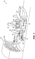
- a mining machine 10 includes a frame 14, a boom 18, and a cutter head 22 supported on the boom 18 for engaging a mine wall 26.
- the frame 14 includes tracks 30 for moving the frame 14 over a support surface or mine floor (not shown).
- the frame 14 further includes a gathering head 32 positioned adjacent the mine floor proximate the cutter head 22.
- the gathering head 32 includes a deck 34 and rotating fingers 38 that urge cut material onto a conveyor (not shown).
- the frame 14 also includes a pair of arms 42 pivotably coupled to the frame 14. The arms 42 can be extended to a position forward of the gathering head 32 in order to direct cut material onto the deck 34.
- the boom 18 is pivotably coupled to the frame 14 at one end, and operation of one or more first actuators 46 pivot, extend, and retract the boom 18 relative to the frame 14.
- the first actuators 46 are hydraulic cylinders.
- the boom 18 pivotably supports the cutter head 22 on an end of the boom 18 opposite the frame 14.
- a second actuator 50 ( FIG. 2 ) pivots the cutter head 22 relative to the boom 18.
- the cutter head 22 is positioned such that the cutter head 22 engages the mine wall 26 with a controlled force.
- Operation of the first actuators 46 moves the boom 18 relative to the frame 14, thereby moving the cutter head 22 over the mine wall 26 to produce a desired cutting profile.
- the angle between the cutter head 22 and the boom 18 is continuously monitored. Sensor data for the angle is provided to a control system for controlling the position of the boom 18.
- the speed of movement of the boom 18 can be adjusted to match the excavation rate, or the energy delivered to the mine wall 26.
- a coupling member or mounting bracket 58 supports the cutter head 22 for pivoting movement relative to the boom 18 ( FIG. 2 ).
- the cutter head 22 includes a first end 62, a second end 66, and a support plate 70 proximate the first end 62.
- the cutter head 22 includes a coupling member or arm 60 for supporting the cutter head 22 on the mounting bracket 58.
- Multiple pins 74 are positioned around the perimeter of the support plate 70 and extend through the support plate 70 and the arm 60. Each pin 74 supports a spring 78, which reacts to the forces exerted on the cutter head 22 by the mine wall 26.
- each pin 74 also supports a damper.
- the geometry and the mass of the cutter head 22 defines a combined center of mass 80 that is generally positioned between the first end 62 and the cutting bit 86.
- the size, shape, and density of the components of the cutter head 22 may be modified to adjust the position of the center of mass 80 relative to the cutting bit 86.
- a different type of cutter head may be coupled to the arm 60 by the pins 74 and springs 78.
- a plate spring or hinge is coupled between the support plate 70 and the boom 18.
- the plate spring is made from a fatigue-resistant material such as a carbon-fiber composite. The plate spring eliminates the need for mechanical pivots and reduces wear on the coupling, thereby improving the working life.
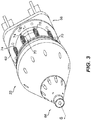
- the cutter head 22 is shown in FIGS. 4-6 .
- the cutter head 22 includes a cutting bit 86 proximate the second end 66, a first or inertial member 90 coupled to the cutting bit 86, and a second or exciter member 94.
- the cutting bit 86 is formed as a ring or disc that is secured to the inertial member 90 to move with the inertial member 90.
- the cutting bit 86 includes a cutting edge 88 ( FIG. 6 ).
- the cutter head 22 further includes a first motor 102, a second motor 106, a slew plate or bearing 110 coupled to the inertial member 90, and a support plate 114 for supporting the first motor 102 and the second motor 106.
- the slew bearing 110 includes a ring gear 118 that is driven by the second motor 106.
- the first motor 102 drives a first shaft 126 ( FIG. 6 ) to rotate the exciter member 94 about an axis of rotation 98.
- the second motor 106 rotates the ring gear 118 and the inertial member 90 about the axis 98.
- the inertial member 90 has a generally frusto-conical shape and tapers in a direction from the first end 62 toward the second end 66. More particularly, the inertial member 90 includes a main body 130, a housing 134 positioned proximate a narrow end of the main body 130, and a sleeve 138 that is positioned with in the body 130 and is coupled to the housing 134. The housing 134 supports the cutting bit 86 proximate the second end 66 of the cutter head 22. In other embodiments, the inertial member 90 may have another construction.
- the tapered shape provides clearance for the cutting bit 86 to engage the mine wall 26 while still permitting the boom 18 to position the cutter head 22 and produce an optimum cutting profile.
- the position and shape of the inertial member 90 are inter-related design factors, and the tapered shape allows a minimum amount of mass to provide a relatively high "equivalent" mass or moment of inertia.
- the tapered shape facilitates cutting along tight corners and performing cut-and-break mining as described in more detail below. It is understood that the cutter head 22 could be used for cutting a mine wall according to other methods (i.e., the cutter head 22 is not limited to cut-and-break mining methods).
- the tapered shape provides a versatile cutter head 22 that permits a variety of cutting profiles while positioning the inertial member 90 as close to the cutting bit 86 as practicable to improve the efficiency of the cutting operation.
- the inertial member 90 may have a different shape or position, depending on the tunnel dimensions, the geometry of the boom, and the optimum effective mass.
- the inertial member 90 may include other configurations, such as a rotating overhung mass 142 (illustrated in FIG. 2 ) that allows clearance in the cutting process, or a plate shaped mass.
- the exciter member 94 is positioned within body 130 and particularly within the sleeve 138 of the inertial member 90.
- the exciter member 94 is supported for rotation relative to the inertial member 90 by high-speed bearings 144.
- the exciter member 94 is elongated and coupled to the first shaft 126 for rotation about the axis of rotation 98.
- the exciter member 94 is a non-contact eccentric and includes at least one lobe 134 that is eccentrically positioned with respect to the axis of rotation 98.
- the exciter member 94 is rotated by the first motor 102, and the rotation of the exciter member 94 "excites" the inertial member 90 and the connected cutting bit 86 and induces a desired oscillation in the inertial member 90 and cutting bit 86.
- the inertial member 90 defines a first mass center 132 that oscillates or orbits about the combined center of mass 80 at a first effective radius.
- the exciter member 94 defines a second mass center 136 that oscillates or orbits about the combined center of mass 80 at a second effective radius.
- movement of the exciter member 94 causes the second mass center 136 to orbit about the combined center of mass 80, thereby causing the first mass center 132 to orbit about the combined center of mass 80.
- the second mass center 136 has a larger effective radius than the first mass center 132.
- the cutter head 22 moves in circular movement about a point 140.
- a reference line 146 extending between the cutting bit 86 and point 140 traces a conical shape as the first mass center 132 oscillates, and the cutting bit 86 moves in a closed path 148 having a dimension that is proportional to the eccentricity of the oscillating motion induced on the inertial member 90.
- the path 148 is circular.
- the reference line 146 defines a radius of the cutting bit 86 from the point 140, and the point 140 defines the apex of the conical shape while the cutting bit 86 moves along the base of the conical shape.
- the dimension of the path 148 is proportional to the mass of the exciter member 94 and the eccentricity (i.e., axial offset) of the exciter member 94.
- the dimension is also inversely proportional to the mass of the inertial member 90.
- the inertial member 90 has an effective mass of 1000 kg at the cutter, while the exciter member 94 has an effective eccentric mass of 40 kg at the cutter and an eccentricity (i.e., an amplitude of eccentric oscillation) of 50 mm.
- the resultant oscillation of the inertial member 90 is proportional to the product of the mass and eccentricity of the exciter member 94 divided by the mass of the inertial member 90; therefore the excitation causes the inertial member of 1000 kg to oscillate or vibrate with an amplitude of ⁇ 2 mm (i.e., the radius of the path 148 of the cutting bit 86 is 2 mm).
- the relative masses of the inertial member 90 and the exciter member 94 as well as the eccentricity of the exciter member 94 can be modified to produce a desired oscillation response in the inertial member 90.
- the wall exerts a reaction force on the cutting bit 86 that resists the oscillating motion of the inertial member 90.
- the feed force is exerted on the cutter head 22 by the boom 18 to urge the cutting bit 86 towards the wall.
- the oscillation of the inertial member 90 and the exciter member 94 is controlled so that the inertial member 90 has a maximum velocity in the direction of the cut when the cutting bit 86 engages the mine wall.
- the cutter head 22 directly secures together the inertial member 90 and the cutting bit 86. Unlike conventional oscillating disc cutters in which all of the dynamic cutting forces are transmitted from a cutting bit and through a bearing arrangement into an inertial mass, the cutter head 22 provides a direct connection between the cutting bit 86 and the inertial member 90. This direct connection permits the inertial member 90 to absorb a significant amount of the dynamic cutting force before the load is transmitted to the bearings 110, 144, thereby reducing the load on the bearings 110, 144. In one embodiment, the high-speed bearing 144 is subject to approximately 5% of the total dynamic cutting forces. The bearings 110, 144 are also sealed from the rock cutting zone.
- the cutter head 22 eliminates dynamic seals in the primary rock cutting zone operating at high speed over large areas. As a result, it is possible to increase both the frequency and the eccentricity of cutter head 22 while also improving the working life of the cutter head 22. Therefore, the cutter head 22 improves the efficiency of the cutting operation.
- the increased frequency and eccentricity permit the cutting bit 86 to exert more dynamic power on the wall to break rock without requiring larger cutter components.
- the frequency (i.e., rotational speed) and the mass of the inertial member 90 as well as the feed force provided by the boom 18 are generally the same as that of a conventional oscillating disc cutter, but the mass and eccentric radius of the exciter member 94 are increased.
- the increased excitation increases inertial member 90 travel (i.e., oscillation amplitude) and results in greater impact energy for the rock cutting process.
- the impact energy is three to four times more than the impact energy provided by a conventional oscillating disc cutter.
- a smaller cutter head 22 can be used to generate the same cutting forces as a conventional cutter head, permitting a lower cost machine that can access and operate in tightly constrained areas of the underground mine.
- the inertial member 90 is sized with the same mass and oscillates at the same frequency as a conventional oscillating disc cutter, but only requires half of the feed force (i.e., the external force applied to the cutter head by the boom 18) to impart the same amount of energy into the rock.
- FIGS. 1 , 7, and 8 illustrate a method for cutting rock from the mine wall 26.
- the method described below refers to the cutter head 22, it is understood that the method may be performed using a cutter head having a different shape or disc cutter configuration, such as a conventional oscillating disc cutter.
- the perimeter of the mine wall 26 is first cut (i.e., a wall relief cut) to define a profile 150 ( FIG. 1 ) of the mine wall 26.
- the profile 150 may be cut by multiple passes of the cutter head 22 in order to increase the depth to a desired level, such as the maximum practical cutting depth of the cutter head 22.
- the depth of the cut is in the range of approximately 200 mm to approximately 400 mm.
- the cutter head 22 subsequently cuts multiple slots 154 into the mine wall 26, leaving uncut rock sections 158 adjacent the slots 154. Cutting the slots 154 may require multiple passes in order to cut the slots 154 to the desired depth.
- the slots 154 are cut in a generally horizontal direction. In other embodiments, the slots 154 may be cut vertically or at an angle across the mine wall 26 in order to facilitate fracturing. Also, the terms "tall", “high”, and “height” as used herein to describe this method generally refer to a vertical dimension of the slots 154 and the uncut sections 158 as shown in the embodiment of FIGS. 1 , 7 and 8 .
- slots 154 and uncut sections 158 in a substantially horizontal orientation, it is understood that the slots 154 and uncut sections 158 could be formed in a different orientation, in which case other terms may be used to refer to the transverse dimension of these features.
- the protruding rock sections 158 above and below the slot 154 are undercut and overcut, respectively, to a maximum allowable depth of the cutting bit 86. That is, a base of each side of the rock section 158 is notched to create a fracture line adjacent the mine wall 26 ( FIG. 7 ). The ends of the protruding rock section 158 are similarly relieved during the perimeter cut. After forming the initial notch 160, the cutter head 22 contacts the protruding rock section 158.
- the mining machine 10 may include a breaker attachment (for example, mounted on a separate boom from the cutter head) that is applied against the rock section 158 to break the rock section 158 along the fracture line.
- a breaker attachment for example, mounted on a separate boom from the cutter head
- the method described above permits the operator to selectively cut rock in such a way to maximize the potential for rock fracturing, and subsequently breaking uncut rock sections 158.
- the "cut-and-break" method described above can mine the rock such that the ratio between the amount of rock that is broken from the wall 26 to the amount of rock that is cut from the wall 26 exceeds 1:1. That is, the method requires cutting less than half of the rock that is removed from the wall 26.
- the method substantially reduces cutting time and energy consumption, and also reduces the wear on the cutting bit 86 and other components of the cutter head 22. In some embodiments, the method described above more than doubles the productivity in underground entry development, when compared with conventional rock cutting processes.
- the cutting bit 86 has a diameter of 400 mm and cuts a slot 154 that is nominally 400 mm tall and 250 mm deep, leaving uncut protruding rock sections 158 that are 200 mm tall and 250 mm deep.
- the cutter velocity is approximately 100 mm per second and cuts a depth of 50 mm per pass.
- the mine wall 26 is generally about 5 m wide by 4.8 m tall.
- the protruding sections 158 are broken from the mine wall 26 as described above.
- the cutting method according to this embodiment requires cutting at least 25% less rock than conventional hard rock cutting methods. This configuration (i.e., a wide cutting bit diameter and narrower uncut rock sections 158) may be particularly useful for mining extremely hard, competent rock (i.e., rock into which unsupported openings may be cut).
- the cutting bit has a diameter of 250 mm and cuts a slot 154 that is nominally 250 mm tall and 250 mm deep, leaving protruding uncut rock sections 158 that are generally 400 mm tall and 250 mm deep.
- the protruding sections 158 are then broken as described above.
- the cutting method according to this embodiment requires cutting less than half of the rock than would be cut using conventional hard rock cutting methods. This configuration (i.e., a narrower cutting bit diameter and relatively wide uncut rock sections 158) may be particularly useful for mining hard rock with shear planes and fractures, or rock that has medium strength.
- the cut-and-break method provides cuts or slots 154 that are separated by uncut rock sections 158, permitting a mining machine 10 to incorporate additional cutter heads 22 supported on additional booms 18 and operating simultaneously, effectively doubling the cutting rate.
- each of the cutter heads 22 in a multiple cutter head arrangement can operate toward one another, effectively counteracting the majority of cutting-induced boom forces that are typically transmitted through the machine 10 and into mine floor or the surrounding rock mass.
- an embodiment including two cutter heads 22 supported on separate booms 18 can impart much larger forces on the protruding rock sections 158, thereby increasing the allowable height of the protruding rock section 158 to be broken.
- Each boom 18 can simultaneously impart loads from an undercut and an overcut position. By maintaining separation between the centers of the booms 18, the cutter heads 22 apply a torque on the rock in addition to exerting a direct force and dynamic cutting action.
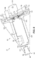
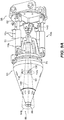
- FIG. 9 illustrates another embodiment in which the cutter head 22 includes an arm 60 coupled to the mounting bracket 58 and supported by multiple hydraulic cylinders 72.
- the illustrated embodiment includes four hydraulic cylinders 72a positioned at approximately 90 degree intervals around the perimeter of the cutter head 22.
- the arm 60 includes a fifth cylinder 72b extending from the center of the support plate 70 to the mounting bracket 58, and the cutter head 22 oscillates about a point 140 at the joint between the cylinder 72b and the mounting bracket 58.
- Other embodiments may include fewer or more hydraulic cylinders.
- the cylinders 72 are coupled to one or more hydraulic accumulators (not shown) such that the cylinders 72 behave similar to the springs 78 to react to the forces exerted on and by the cutter head 22.
- the hydraulic cylinders 72a can be actuated to pivot the cutter head 22 relative to the mounting bracket 58, and the center cylinder 72b extends the cutter head 22 relative to the mounting bracket 58.
- the operation of the cylinders 72 provides omni-directional control of the cutter head 22 in order to maintain a desired orientation of the cutter head 22 relative to the mine wall 26 (i.e., the angle of attack).
- the cylinders 72 can more accurately sense the force feedback from the cutter head 22, providing accurate measurement of the cutting force exerted by the cutter head 22 and permitting the operator to more precisely control the cutting force.
- An automated system controls the cutting force based on various factors, such as oscillation frequency or speed, mass of the inertial member, and eccentricity of the exciter member.
- a different type of cutter head may be coupled to the mounting bracket 58 by the cylinders 72.
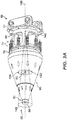
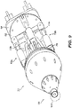
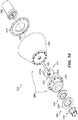
- FIGS. 10 and 11 illustrate a cutter head 222 according to another embodiment.
- the cutter head 22 is generally similar to the cutter head 22 described above with respect to FIGS. 4-6 , and similar features are identified by similar reference numbers, plus 200.
- the cutter head 222 includes a cutting bit 286, an inertial member 290, an exciter member 294, and a motor 302 for driving the exciter member 294.
- the inertial member includes a body 330 and a cap 332 coupled to an end of the body 330.
- the cutting bit 286 generally has a ring or annular shape and includes a cutting edge 288.
- the cutting bit 286 is coupled to an end of the cap 332 by a retaining ring 336 ( FIG. 10 ).
- a radial and thrust bearing plate 340 ( FIG. 10 ) is positioned between the cutting bit 286 and the end of the cap 332 to support the cutting bit 286 for rotation relative to the cap 332.
- the bearing plate 340 supports the cutting bit 286 against radial and axial loads.
- the exciter member 294 includes an eccentric mass 334 coupled to a shaft 326.
- the mass 334 has two lobes 334a, 334b that are eccentrically positioned with respect to the axis of rotation 298.
- the shaft 326 is driven about the axis 298 by the motor 302.
- the motor 302 is coupled to a support plate 270 of the cutter head 222.
- the inertial member 290 is rotatably coupled to the support plate 270 by a bearing 308, and therefore the inertial member 290 is freely rotatable.
- the cutting bit 286 is freely rotatable relative to the inertial member 290 due to the bearing plate 340.
- the inertial member 290 rotates about the axis 298 due to oscillation induced by the rotation of the exciter member 294.
- the cutting bit 286 rotates at a relatively low speed due to the reaction forces exerted on the cutting bit 286 by the rock of the mine wall.
- the cutting bit has a diameter of 400 mm and rotates at a speed of approximately 30 RPM.
- the lobes 334a, 334b of the exciter member 294 rotate independently of one another.
- the first motor 302 engages a first gear 316 that is coupled to a first or outer shaft 326a.
- the first lobe 334a is coupled to the outer shaft 326a, and operation of the first motor 302 drives the first lobe 334a to rotate about the axis 298.
- the cutter head 222 also includes a second motor 304 engaging a second gear 320 that is coupled to a second or inner shaft 326b.
- the second lobe 334b is coupled to the inner shaft 326b, and operation of the second motor 306 drives the second lobe 334b to rotate about the axis 298.
- the relationship between the lobes 334a, 334b can be tuned to provide a desired moment of inertia.
- the lobes 334a, 334b can be moved to diametrically opposed positions (i.e., the angle between the lobes 334a, 334b is 180 degrees). If the lobes 334a, 334b have the same mass, this configuration effectively cancels or "turns off the excitation.
- the lobes 334a, 334b are positioned in the same relative position about the shaft 326, the maximum power is delivered to the inertial member 290.
- the lobes 334a, 334b are counter-rotating such that the lobe 334a rotates about the axis 298 in a first direction while the other lobe 334b rotates about the axis 298 in an opposite second direction.
- the cutter head 222 produces a jackhammer-like action on the cutting edge of the cutting bit. Due to the configuration of the cutting bit 286, the jackhammer effect acts at a 90 degree angle.
- the counter-rotating exciter member 294 will drive the edge of the cutting bit 286 along a path 148 ( FIG. 3A ) having an elliptical shape.
- the cutter head 222 includes an internal fluid flow path 370 for a cutting clearance system.
- the flow path 370 is in fluid communication with a fluid source, such as a pump (not shown).
- the flow path 370 includes a first passage 374 extending through the shaft 326 of the exciter member 294 and multiple second passages 378 extending through the cutting bit 286.
- the first passage 374 extends into a ring carrier of the cutting bit 286 and is in fluid communication with the second passage 378.
- the second passages 378 extend radially (i.e., in a direction that is non-parallel to the axis 298) from the first passage 374 through the cutting bit 286 to nozzles 382 positioned along the perimeter of the cutting bit 286 between the cutting tips 386 ( FIG. 14 ).
- the clearance fluid e.g., water
- the fluid discharge path is aligned with the primary cutting direction.
- the cutting clearance system eliminates hoses or other fluid conduit near the cutting interface. Furthermore, the cutting clearance system does not require additional moving parts inside the cutter head 222, since the first passage 374 is fixed and statically sealed to the cutting bit 286. In addition, embedding the nozzles 382 in the cutting bit 286 reduces the potential for damage to the fluid circuit or blockage caused by cuttings or debris.
- the mining machine 10 monitors certain characteristics of the cutter head 22 and incorporates feedback from the cutting interface to adjust certain parameters.
- the mining machine 10 detects changes in conditions of the cutting operation (e.g., a change in rock hardness or density) and incorporates the sensed information into a feedback control loop to modify the operating parameters of the cutter head 22 and optimize cutting performance.
- Such operating parameters may include the depth of cut, the angle of attack of the cutting bit 86 relative to the mine wall, the eccentricity of the exciter member 94, the oscillation frequency of the exciter member 94.
- Other factors may be modified through manual adjustments.
- the cutting effectiveness of the cutter head 22 at least partially depends on the velocity of the inertial member 90 in the direction of cutting at the moment the cutting bit 86 impacts the mine wall, and on the frequency of the impacts between the cutting bit 86 and the mine wall.
- the velocity and frequency are controlled to optimize the velocity and the frequency of the impact of the cutter head 22 with the mine wall.
- the velocity and frequency can be controlled through various parameters, such as the effective mass of the exciter member 94, operating frequency of the exciter member 94, the stiffness of the cutter head 22 coupling member, the feed force from the boom, etc.
- the cutting bit 86 moves in a generally circular or elliptical motion to engage the mine wall.
- the control system synchronizes the oscillation of the inertial member 90 with the motion of the cutting bit 86 such that the cutting bit 86 engages the mine wall when the momentum of the inertial member 90 is directed substantially into the mine wall.
- This timing between the cutting bit's engagement in the wall and the motion of the inertial member 90 maximizes the velocity of the inertial member 90 in the direction of the wall, thereby maximizing the kinetic energy imparted to the wall by the cutter head 22.
- the cutting bit 86 may trace a different shaped path, the bit 86 may engage the wall at a different position along the path 148, and/or the oscillation of the inertial member 90 may be synchronized to deliver maximum velocity at a different position along the path 148.
- control system adjusts the force exerted by the boom 18 and varies the oscillation frequency of the exciter member 94 in order to increase or decrease cutting energy. These modifications optimize productivity by increasing cutting velocity when possible.
- condition of the tool may be monitored to detect changes in productivity and feed force as the cutting bit becomes blunt.
- the cutter head 22 is controlled by directly sensing an indicator of the force exerted by the cutting bit 86 on the mine wall 26 in real-time.
- the control system may include a load cell (e.g., a multi-axis strain gauge; not shown) positioned on the cutting bit 86 to detect the stress on the cutting bit. The cutting force is calculated based on the measured stress.
- the control system may include sensors, such as infrared sensors, for monitoring the temperature at the cutting interface. The load sensor and thermal sensor provide accurate measurements of the performance of the cutter head 22, permitting accurate adjustment of certain parameters (such as cutting speed or feed force) in order to optimize the closed loop control and optimize the power provided at the cutting interface.
- the control system includes measuring a cutting speed of the cutting bit 86 with non-contact sensors and varying a feed rate of the cutter head 22 to optimize a cutting rate. Other embodiments can incorporate other adaptive features to optimize performance of the cutter head 22.
- a cutter head 22 In general, increasing the power delivered by a cutter head 22 to the mine wall 26 generally results in a larger amount of rock cut from the wall 26.
- the power delivered by the cutter head 22 varies depending on the rotation speed of the cutting bit 86, the eccentricity of the cutting bit 86, the mass of the inertial member 90 and the exciter member 94, and the cutting feed force.
- one or more of these parameters remain fixed due to the inherent characteristics of the mining machine 10 and the remaining parameters are dynamically controlled to continuously monitor and optimize the power output of the cutter head 22. For example, a selected parameter may be varied slightly and the system detects whether the variation increases the cutting rate. If so, the selected parameter is adjusted further in the same direction. Otherwise, the parameter is adjusted in the opposite direction and any change in the cutting rate is monitored. The process is frequently repeated to ensure that the machine is generating maximum power output.
- control system provides automated position and force control of the boom 18.
- the cutter head consistently operates at maximum capacity and at an optimum setting.
- the magnitude and direction of a load on the machine is known and controlled.
- the cutting force is the same for different applications, conditions, rock types etc., but the production rate varies depending on these parameters. Because the system is optimally tuned for substantially all conditions, it is not necessary to change the parameters if the mine conditions change (e.g., if the rock density changes).
- the cutting operation can be slowed down if required by reducing the oscillation speed of the cutting bit 86 and/or the exciter mass 94.
- the mining machine includes multiple cutter heads 22 coupled to a common boom 18.
- Each cutter head 22 is force-controlled as described above, while the common boom 18 is position-controlled.
- Each cutter head 22 constitutes a single cutter system with the position-controlled common boom 18 as described above; however, each cutter system is linked via the common boom 18.
- the multiple cutter system is controlled to progress through the mine wall 26 at a rate that is determined by the least productive individual cutter head 22 (i.e., the master cutter head).
- the more productive cutter head systems i.e., slave cutter heads
- the slave cutter(s) are de-tuned by altering one of the operating parameters, (e.g., the rotation speed of the cutting bit). For example, a master cutter head operates at nominal speed, while the slave cutter heads operate at speeds slower than the rated value. If a slave cutter head begins to lag, its speed is increased until its cutting performance matches the master cutter.
- the parameter(s) of the master cutter head are continuously varied to maximize its power output as described above with respect to the single cutter head system.
- the slave cutter If the speed of one of the slave cutter heads is adjusted to exceed the nominal cutting speed due to, for example, a change in cutting conditions, the slave cutter is automatically designated the master cutter head and the previous master cutter head becomes a slave. Therefore, the poorest performing cutter head is continuously adjusted to achieve its maximum possible performance and the other cutter heads are controlled to match this performance, thereby achieving maximum performance of the combined cutter head assembly.
- a significant discrepancy in the relative performance of the cutter heads indicates either differing rock characteristics or cutter condition problems.
- the invention provides, among otherthings, a cutter head for a mining machine.
Abstract
Description
- This application claims the benefit of and priority to
U.S. Provisional Patent Application No. 61/701,256, filed September 14, 2012 - The present invention relates to underground mining machines, and in particular to a cutter head for an underground mining machine.
- A hard rock continuous miner includes a cutter head having an oscillating cutting disc. The oscillating disc cutter transmits all of the dynamic cutting forces through the bearings, and the life of the bearings are limited due to the high loads and high speed of the cutting discs. In addition, the oscillating discs require large face seal surface areas in the primary cutting area, while the cutting discs oscillate at frequencies typically around 50 Hz. It is difficult to seal a large area with a high surface velocity, and this is further complicated due to the fact that the cutting operation generates a large amount of highly abrasive rock particles. The combination of the contaminated environment and high surface velocity accelerates wear on the seals and decreases the working life of the seals. Furthermore, the deficiencies in the seals and the highly loaded bearings can combine to even further increase maintenance and replacement of the disc cutter assembly. These factors also limit the frequency and the eccentricity of oscillation of the cutting discs, thereby limiting the total power available for rock cutting
- In addition, oscillating disc cutter systems typically lack a means for directly monitoring the behavior of the disc cutter at the cutting surface. As a result, it is difficult to sense a change in the cutting conditions (e.g., when the hardness of the rock changes). Thus, the operator is unable to control the disc cutter to optimize the cutting performance.
- In some aspects the invention provides a cutter head for a mining machine including a frame and a boom movably coupled to the frame. The cutter head includes a first member, a cutting bit, and a second member. The first member includes a first end and a second end and includes a first mass. The cutting bit is coupled to the first member proximate the second end and includes a cutting edge. The second member is rotatable about an axis and includes a second mass eccentrically positioned with respect to the axis. The second mass and the first mass at least partially define a combined center of mass. Rotation of the second mass causes the first member and the cutting bit to oscillate about the combined center of mass along a closed path.
- In other aspects the invention provides a mining machine including a frame for supporting the machine on a support surface, a boom, and a cutter head. The boom includes a first end coupled to the frame and a second end positioned away from the frame. The cutter head a cutter head coupled to the second end of the boom, the cutter head includes a first member, a cutting bit, and a second member. The first member defines a first end and a second end and includes a first mass and a coupling member supporting the first mass on the second end of the boom. The cutting bit is coupled to the first member proximate the second end and includes a cutting edge. The first member and the cutting bit at least partially define a first mass center. The second member is rotatable about an axis and includes a second mass eccentrically positioned with respect to the axis. The second mass defines a second mass center. The first mass center and the second mass center define a combined center of mass. Rotation of the second mass about the axis causing the first member and the cutting bit to oscillate about the combined center of mass along a closed path.
- In still other aspects the invention provides a mining machine including a frame for supporting the machine on a support surface, a boom, a cutter head, and a coupling member. The boom includes a first end coupled to the frame and a second end positioned away from the frame; the second end includes a bracket. The cutter head includes a first member and a cutting bit. The first member includes a first end coupled to the bracket and a second end. The cutting bit is coupled to the first member proximate the second end. The coupling member supporting the first member on the second end of the boom to facilitate oscillation of the cutter head relative to the boom.
- In still other aspects the invention provides a cutter head for a mining machine including a frame and a boom movably coupled to the frame. The cutter head includes a first member, a cutting bit, a fluid conduit, and a plurality of nozzles. The first member includes a first end and a second end and is movable relative to the second end. The cutting bit is coupled to the first member proximate the second end. The fluid conduit extends through the first member and is configured to be in fluid communication with a fluid source. The nozzles are positioned on the cutting edge, the nozzles in fluid communication with the fluid conduit.
- In still other aspects, the invention provides a method for removing material from a rock wall. The method includes moving a cutting edge through the rock wall to create a first slot in the rock wall; moving the cutting edge through the rock wall to create a second slot in the rock wall, the second slot being separated from the first slot by an uncut portion, the uncut portion defining a base surface attached to the wall; cutting a notch into the base surface of the uncut portion; and applying a force on the uncut portion to break the uncut portion away from the wall.
- In still other aspects, the invention provides a method for controlling a mining machine. The method includes sensing a value of an indicator of a cutting efficiency of a cutter head; comparing the sensed value with a desired value; modifying an operating parameter in a first direction from an initial value to a second value; detecting the change in the indicator of cutting efficiency; and when the change in the indicator of the cutting efficiency represents an improvement, modifying the operating parameter further in the first direction to a third value.
- In still other aspects, the invention provides a method for controlling a mining machine. The method includes sensing a first value of an indicator of a cutting efficiency of a first cutter; sensing a second value of an indicator of cutting efficiency of a second cutter; comparing the first value with the second value to detect whether the first value is less than the second value; when the first value is less than the second value, modifying an operating parameter of the second cutter so that the second value matches the first value.
- Other aspects of the invention will become apparent by consideration of the detailed description and accompanying drawings.
- According to an aspect of the invention a cutter head for a mining machine, mining machine including a frame and a boom movably coupled to the frame, the cutter head comprising: a first member including a first end and a second end and including a first mass; a cutting bit coupled to the first member proximate the second end, the cutting bit including a cutting edge; and a second member rotatable about an axis and including a second mass eccentrically positioned with respect to the axis, the second mass and the first mass at least partially defining a combined center of mass, rotation of the second mass causing the first member and the cutting bit to oscillate about the combined center of mass along a closed path.
- The first member may include a coupling member adapted to support the first member relative to an end of the boom.
- The coupling member may include a resilient member permitting oscillation of the cutter head relative to an end of the boom.
- The coupling member may include a ball joint permitting oscillation of the cutter head relative to an end of the boom.
- The second mass may oscillate about the combined center of mass at an effective radius, wherein a dimension of the closed path is proportional to the mass of the second member and the effective radius.
- The first member may define a first mass center and the second member may define a second mass center, the first mass center and the second mass center define the combined center of mass, wherein the first mass center moves in an orbital manner about the combined center of mass and the second mass center moves in an orbital manner about the combined center of mass.
- When a reference line extends from the cutting bit to the first end of the first member, and wherein the oscillation of the first member and the cutting bit may move the reference line and cause the reference line to trace a conical shape having a circular base, the closed path being coextensive with the base, an apex of the cone being positioned at the first end of the first member.
- The first member may have a tapered shape such that the first end is wider than the second end.
- The cutter head may further comprise a motor driving the second member about the axis, wherein the center of mass is also defined by the motor and the second member.
- The motor may be a first motor and the cutter head may further comprise a second motor for rotating the first member.
- The second member may include a first lobe movable about the axis and a second lobe movable about the axis, the second lobe being movable about the axis relative to the first lobe.
- The first lobe may rotate about the axis in a first direction and the second lobe may rotate about the axis in a second direction opposite the first direction.
- The cutter head may further comprise a first motor and a second motor, wherein the first lobe is coupled to a first shaft driven by the first motor, and the second lobe is coupled to a second shaft driven by the second motor.
- The second member may include a shaft coupled to the second mass for rotation about the axis, the shaft including a first fluid conduit extending through the shaft, and wherein the cutting bit further includes a second fluid conduit in fluid communication with the first fluid conduit, the second fluid conduit extending radially through the cutting bit.
- The cutting bit may include a ring, a plurality of cutting tips positioned around a perimeter of the ring, and a plurality of nozzles in fluid communication with the second fluid conduit.
- Each nozzle may be positioned between adjacent cutting tips.
- The cutting bit may be rotatable relative to the first member.
- According to another aspect of the invention a mining machine comprises: a frame for supporting the machine on a support surface; a boom including a first end coupled to the frame and a second end positioned away from the frame; and a cutter head coupled to the second end of the boom, the cutter head including a first member defining a first end and a second end and including a first mass and a coupling member supporting the first mass on the second end of the boom, a cutting bit coupled to the first member proximate the second end and including a cutting edge, the first member and the cutting bit at least partially defining a first mass center; and a second member rotatable about an axis and including a second mass eccentrically positioned with respect to the axis, the second mass defining a second mass center, the first mass center and the second mass center defining a combined center of mass, rotation of the second mass about the axis causing the first member and the cutting bit to oscillate about the combined center of mass along a closed path.
- The coupling member may include a resilient member permitting oscillation of the cutter head relative to the second end of the boom.
- The resilient member may include at least one pin and a spring, the pin extending between the first end of the first member and the second end of the boom, the spring positioned around the pin to exert a spring force on the first member.
- The resilient member may include at least one hydraulic cylinder positioned between the first end of the first member and the second end of the boom, each cylinder being extendable and retractable to change an angle of the cutter head relative to the boom.
- The coupling member may include a ball joint permitting the first member to oscillate relative to the second end of the boom.
- The dimension of the closed path may be proportional to the mass of the second member and the eccentricity of the second mass.
- When a reference line extends from the cutting bit to the first end of the first member, and wherein the oscillation of the first member and the cutting bit may move the reference line, causing the reference line to trace a conical shape having a circular base generally corresponding to the closed path.
- The first mass center may move in an orbital manner about the combined center of mass and the second mass center moves in an orbital manner about the combined center of mass.
- When a reference line extends from the cutting bit to the first end of the first member, and wherein the oscillation of the first member and the cutting bit may move the reference line and causes the reference line to trace a conical shape having a circular base, the closed path being coextensive with the base, an apex of the cone being positioned at the first end of the first member.
- The first member may have a tapered shape such that the first end is wider than the second end.
- The cutter head may further include a motor driving the second member about the axis.
- The motor may be a first motor and the cutter head may further include a second motor for rotating the first member.
- The second mass may include a first lobe and a second lobe, the second lobe being movable about the axis relative to the first lobe.
- The first lobe may rotate about the axis in a first direction and the second lobe may rotate about the axis in a second direction opposite the first direction.
- The cutter head may further include a first motor and a second motor, wherein the first lobe is coupled to a first shaft driven by the first motor, and the second lobe is coupled to a second shaft driven by the second motor.
- According to another aspect of the invention a mining machine comprises: a frame for supporting the machine on a support surface; a boom including a first end coupled to the frame and a second end positioned away from the frame; a cutter head including a first member and a cutting bit, the first member including a first end coupled to the bracket and a second end, the cutting bit coupled to the first member proximate the second end; and a coupling member supporting the first member on the second end of the boom to facilitate oscillation of the cutter head relative to the boom.
- The cutter head may further include an eccentric member rotatable about an axis of rotation that generally extends between the first end and the second end, rotation of the eccentric member inducing the first member and the cutting bit to oscillate relative to the resilient member about a center of mass.
- The coupling member may include at least one spring and a pin extending through the spring and between the first end of the first member and the bracket, the spring exerting a spring force on the first member to bias the first member against a reaction force exerted on the cutting bit.
- The coupling member may include at least one hydraulic cylinder positioned between the first end of the first member and the bracket, the cylinder being extendable and retractable to change an orientation of the cutter head relative to the boom.
- The coupling member may include at least one hydraulic cylinder positioned between the first end of the first member and the bracket, the cylinder being extendable and retractable to modify an oscillation of the first member and the cutting bit about the center of mass.
- The coupling member may include a ball joint permitting the first member to oscillate relative to the second end of the boom.
- According to another aspect of the invention there is provided a cutter head for a mining machine, the mining machine including a frame and a boom movably coupled to the frame, the cutter head comprising: a first member including a first end and a second end, the first member being movable relative to the second end; a cutting bit coupled to the first member proximate the second end; and a fluid conduit extending through the first member and configured to be in fluid communication with a fluid source; and
a plurality of nozzles positioned on the cutting edge, the nozzles in fluid communication with the fluid conduit. - The fluid conduit may include first conduit and a second conduit, the first conduit extending through the first member in a direction generally parallel to the axis, the second conduit extending through the cutting bit and providing fluid communication between the first conduit and the nozzles, the second conduit extending in a direction that is angled with respect to the axis.
- The cutter head may further comprise a second member and a motor, the second member positioned within the first member and coupled to a shaft, the motor driving the shaft to rotate about the axis, the fluid conduit extending through the shaft.
- The cutting edge may have a generally circular perimeter and includes a plurality of cutting tips positioned at regular intervals around the perimeter, and wherein each nozzle is positioned between adjacent cutting tips.
- According to another aspect of the invention there is provided a method for removing material from a rock wall, the method comprising: moving a cutting edge through the rock wall to create a first slot in the rock wall; moving the cutting edge through the rock wall to create a second slot in the rock wall, the second slot being separated from the first slot by an uncut portion, the uncut portion defining a base surface attached to the wall; cutting a notch into the base surface of the uncut portion; and applying a force on the uncut portion to break the uncut portion away from the wall.
- The method may further comprise, prior to moving a cutting edge through the rock wall to create the first slot, cutting a profile around the perimeter of the rock wall.
- The method, wherein applying a force on the uncut portion may include contacting the uncut portion with a vibrating mass in order to induce the uncut portion to break away from the rock wall.
- The vibrating mass may be a cutter head supporting the cutting edge.
- The first slot and the second slot may be generally parallel.
- The first slot and the second slot are substantially horizontal.
- Moving the cutting edge through the rock wall to create the second slot provides a second slot that is at least as tall as the uncut portion.
- According to another aspect of the invention there is provided a method for controlling a mining machine, the method comprising: sensing a value of an indicator of a cutting efficiency of a cutter head; comparing the sensed value with a desired value; modifying an operating parameter in a first direction from an initial value to a second value; detecting the change in the indicator of cutting energy; and when the change in the indicator of the cutting efficiency represents an improvement, modifying the operating parameter further in the first direction to a third value.
- The indicator may be a strain exerted on a cutting bit engaging the rock wall.
- The indicator may be a cutting energy transferred from the cutter head to the rock wall.
- The operating parameter may be an oscillating frequency of an eccentric mass positioned within the cutter head.
- The operating parameter may be an oscillating amplitude of an eccentric mass positioned within the cutter head.
- The sensed value may include an angular position of a cutting bit against the rock wall and the angular direction of the momentum of an inertial mass relative to the angular position of the cutting bit, and wherein modifying the operating parameter includes modifying an oscillation of the inertial mass to change the direction of the momentum of the inertial mass when the cutting bit engages the rock wall.
- The sensed value may include a cutting feed rate of the cutter head.
- The method may further include, if the indicator of cutting energy degrades, modifying the operating parameter to its initial value.
- According to another aspect of the invention, there is provided a method for controlling a mining machine, the method comprising: sensing a first value of an indicator of a cutting efficiency of a first cutter; sensing a second value of an indicator of cutting efficiency of a second cutter; comparing the first value with the second value to detect whether the first value is less than the second value; when the first value is less than the second value, modifying an operating parameter of the second cutter so that the second value matches the first value.
- The method may further include maintaining the operating parameter of the second cutter so that the second value does not exceed the first value.
-
-
FIG. 1 is a perspective view of a mining machine engaging a mine wall. -
FIG. 2 is a front perspective view of the mining machine ofFIG. 1 . -
FIG. 3 is a perspective view of a cutter head. -
FIG. 3A is a side perspective view of the cutter head ofFIG. 3 . -
FIG. 4 is an exploded front perspective view of the cutter head ofFIG. 3 . -
FIG. 5 is an exploded rear perspective view of the cutter head ofFIG. 3 . -
FIG. 6 is a section view of the cutter head ofFIG. 3 taken along theline 6--6. -
FIG. 7 is a side view of a cutter head engaging a mine wall. -
FIG. 8 is an enlarged side view of a cutter head engaging a mine wall. -
FIG. 9 is a perspective view of a cutter head according to another embodiment. -
FIG. 9A is a side perspective view of the cutter head ofFIG. 9 . -
FIG. 10 is an exploded perspective view of a cutter head according to another embodiment. -
FIG. 11 is a section view of the cutter head ofFIG. 10 taken along the line 11--11. -
FIG. 12 is a section view of a cutter head according to another embodiment. -
FIG. 13 is a section view of the cutter head ofFIG. 12 showing a fluid flow path. -
FIG. 14 is a perspective view of a cutting bit. - Before any embodiments of the invention are explained in detail, it is to be understood that the invention is not limited in its application to the details of construction and the arrangement of components set forth in the following description or illustrated in the following drawings. The invention is capable of other embodiments and of being practiced or of being carried out in various ways. Also, it is to be understood that the phraseology and terminology used herein is for the purpose of description and should not be regarded as limiting. The use of "including," "comprising" or "having" and variations thereof herein is meant to encompass the items listed thereafter and equivalents thereof as well as additional items. The terms "mounted," "connected" and "coupled" are used broadly and encompass both direct and indirect mounting, connecting and coupling. Further, "connected" and "coupled" are not restricted to physical or mechanical connections or couplings, and can include electrical or hydraulic connections or couplings, whether direct or indirect. Also, electronic communications and notifications may be performed using any known means including direct connections, wireless connections, etc.
- As shown in
FIGS. 1 and2 , amining machine 10 includes aframe 14, aboom 18, and acutter head 22 supported on theboom 18 for engaging amine wall 26. Theframe 14 includestracks 30 for moving theframe 14 over a support surface or mine floor (not shown). Theframe 14 further includes a gatheringhead 32 positioned adjacent the mine floor proximate thecutter head 22. The gatheringhead 32 includes adeck 34 androtating fingers 38 that urge cut material onto a conveyor (not shown). Theframe 14 also includes a pair ofarms 42 pivotably coupled to theframe 14. Thearms 42 can be extended to a position forward of the gatheringhead 32 in order to direct cut material onto thedeck 34. - The
boom 18 is pivotably coupled to theframe 14 at one end, and operation of one or morefirst actuators 46 pivot, extend, and retract theboom 18 relative to theframe 14. In the illustrated embodiment, thefirst actuators 46 are hydraulic cylinders. Also, in the illustrated embodiment, theboom 18 pivotably supports thecutter head 22 on an end of theboom 18 opposite theframe 14. A second actuator 50 (FIG. 2 ) pivots thecutter head 22 relative to theboom 18. Thecutter head 22 is positioned such that thecutter head 22 engages themine wall 26 with a controlled force. Operation of thefirst actuators 46 moves theboom 18 relative to theframe 14, thereby moving thecutter head 22 over themine wall 26 to produce a desired cutting profile. The angle between thecutter head 22 and theboom 18 is continuously monitored. Sensor data for the angle is provided to a control system for controlling the position of theboom 18. The speed of movement of theboom 18 can be adjusted to match the excavation rate, or the energy delivered to themine wall 26. - As shown in
FIG. 3 , a coupling member or mountingbracket 58 supports thecutter head 22 for pivoting movement relative to the boom 18 (FIG. 2 ). In the embodiment ofFIG. 3 , thecutter head 22 includes afirst end 62, asecond end 66, and asupport plate 70 proximate thefirst end 62. In the illustrated embodiment thecutter head 22 includes a coupling member orarm 60 for supporting thecutter head 22 on the mountingbracket 58.Multiple pins 74 are positioned around the perimeter of thesupport plate 70 and extend through thesupport plate 70 and thearm 60. Eachpin 74 supports aspring 78, which reacts to the forces exerted on thecutter head 22 by themine wall 26. Thesprings 78 also isolate theboom 18 against transmission of vibrational forces from thecutter head 22. In some embodiments, eachpin 74 also supports a damper. Referring toFIG. 3A , the geometry and the mass of thecutter head 22 defines a combined center ofmass 80 that is generally positioned between thefirst end 62 and the cuttingbit 86. The size, shape, and density of the components of thecutter head 22 may be modified to adjust the position of the center ofmass 80 relative to the cuttingbit 86. - In other embodiments, a different type of cutter head (including a cutter head having a conventional oscillating disc cutter) may be coupled to the
arm 60 by thepins 74 and springs 78. In still other embodiments, a plate spring or hinge is coupled between thesupport plate 70 and theboom 18. The plate spring is made from a fatigue-resistant material such as a carbon-fiber composite. The plate spring eliminates the need for mechanical pivots and reduces wear on the coupling, thereby improving the working life. - The
cutter head 22 is shown inFIGS. 4-6 . Thecutter head 22 includes a cuttingbit 86 proximate thesecond end 66, a first orinertial member 90 coupled to the cuttingbit 86, and a second orexciter member 94. In the illustrated embodiment, the cuttingbit 86 is formed as a ring or disc that is secured to theinertial member 90 to move with theinertial member 90. The cuttingbit 86 includes a cutting edge 88 (FIG. 6 ). Thecutter head 22 further includes afirst motor 102, asecond motor 106, a slew plate or bearing 110 coupled to theinertial member 90, and asupport plate 114 for supporting thefirst motor 102 and thesecond motor 106. The slew bearing 110 includes aring gear 118 that is driven by thesecond motor 106. As best shown inFIG. 6 , thefirst motor 102 drives a first shaft 126 (FIG. 6 ) to rotate theexciter member 94 about an axis ofrotation 98. In one embodiment, thesecond motor 106 rotates thering gear 118 and theinertial member 90 about theaxis 98. - In the embodiment of
FIGS. 4-6 , theinertial member 90 has a generally frusto-conical shape and tapers in a direction from thefirst end 62 toward thesecond end 66. More particularly, theinertial member 90 includes amain body 130, ahousing 134 positioned proximate a narrow end of themain body 130, and asleeve 138 that is positioned with in thebody 130 and is coupled to thehousing 134. Thehousing 134 supports the cuttingbit 86 proximate thesecond end 66 of thecutter head 22. In other embodiments, theinertial member 90 may have another construction. - The tapered shape provides clearance for the cutting
bit 86 to engage themine wall 26 while still permitting theboom 18 to position thecutter head 22 and produce an optimum cutting profile. The position and shape of theinertial member 90 are inter-related design factors, and the tapered shape allows a minimum amount of mass to provide a relatively high "equivalent" mass or moment of inertia. In addition, the tapered shape facilitates cutting along tight corners and performing cut-and-break mining as described in more detail below. It is understood that thecutter head 22 could be used for cutting a mine wall according to other methods (i.e., thecutter head 22 is not limited to cut-and-break mining methods). In general, the tapered shape provides aversatile cutter head 22 that permits a variety of cutting profiles while positioning theinertial member 90 as close to the cuttingbit 86 as practicable to improve the efficiency of the cutting operation. - In other embodiments, the
inertial member 90 may have a different shape or position, depending on the tunnel dimensions, the geometry of the boom, and the optimum effective mass. Theinertial member 90 may include other configurations, such as a rotating overhung mass 142 (illustrated inFIG. 2 ) that allows clearance in the cutting process, or a plate shaped mass. - Referring to
FIG. 6 , theexciter member 94 is positioned withinbody 130 and particularly within thesleeve 138 of theinertial member 90. Theexciter member 94 is supported for rotation relative to theinertial member 90 by high-speed bearings 144. Theexciter member 94 is elongated and coupled to thefirst shaft 126 for rotation about the axis ofrotation 98. Theexciter member 94 is a non-contact eccentric and includes at least onelobe 134 that is eccentrically positioned with respect to the axis ofrotation 98. - The
exciter member 94 is rotated by thefirst motor 102, and the rotation of theexciter member 94 "excites" theinertial member 90 and the connected cuttingbit 86 and induces a desired oscillation in theinertial member 90 and cuttingbit 86. As shown inFIG. 3A , theinertial member 90 defines a firstmass center 132 that oscillates or orbits about the combined center ofmass 80 at a first effective radius. Theexciter member 94 defines a secondmass center 136 that oscillates or orbits about the combined center ofmass 80 at a second effective radius. As shown, movement of theexciter member 94 causes the secondmass center 136 to orbit about the combined center ofmass 80, thereby causing the firstmass center 132 to orbit about the combined center ofmass 80. In the illustrated embodiment, the secondmass center 136 has a larger effective radius than the firstmass center 132. Thecutter head 22 moves in circular movement about apoint 140. Stated another way, areference line 146 extending between the cuttingbit 86 andpoint 140 traces a conical shape as the firstmass center 132 oscillates, and the cuttingbit 86 moves in aclosed path 148 having a dimension that is proportional to the eccentricity of the oscillating motion induced on theinertial member 90. In the illustrated embodiment, thepath 148 is circular. Thereference line 146 defines a radius of the cuttingbit 86 from thepoint 140, and thepoint 140 defines the apex of the conical shape while the cuttingbit 86 moves along the base of the conical shape. - More specifically, the dimension of the
path 148 is proportional to the mass of theexciter member 94 and the eccentricity (i.e., axial offset) of theexciter member 94. The dimension is also inversely proportional to the mass of theinertial member 90. For example, in one embodiment theinertial member 90 has an effective mass of 1000 kg at the cutter, while theexciter member 94 has an effective eccentric mass of 40 kg at the cutter and an eccentricity (i.e., an amplitude of eccentric oscillation) of 50 mm. The resultant oscillation of theinertial member 90 is proportional to the product of the mass and eccentricity of theexciter member 94 divided by the mass of theinertial member 90; therefore the excitation causes the inertial member of 1000 kg to oscillate or vibrate with an amplitude of ± 2 mm (i.e., the radius of thepath 148 of the cuttingbit 86 is 2 mm). In other embodiments, the relative masses of theinertial member 90 and theexciter member 94 as well as the eccentricity of theexciter member 94 can be modified to produce a desired oscillation response in theinertial member 90. - When the cutting
bit 86 contacts mine wall, the wall exerts a reaction force on the cuttingbit 86 that resists the oscillating motion of theinertial member 90. To compensate, the feed force is exerted on thecutter head 22 by theboom 18 to urge the cuttingbit 86 towards the wall. The oscillation of theinertial member 90 and theexciter member 94 is controlled so that theinertial member 90 has a maximum velocity in the direction of the cut when the cuttingbit 86 engages the mine wall. - The
cutter head 22 directly secures together theinertial member 90 and the cuttingbit 86. Unlike conventional oscillating disc cutters in which all of the dynamic cutting forces are transmitted from a cutting bit and through a bearing arrangement into an inertial mass, thecutter head 22 provides a direct connection between the cuttingbit 86 and theinertial member 90. This direct connection permits theinertial member 90 to absorb a significant amount of the dynamic cutting force before the load is transmitted to thebearings bearings speed bearing 144 is subject to approximately 5% of the total dynamic cutting forces. Thebearings cutter head 22 eliminates dynamic seals in the primary rock cutting zone operating at high speed over large areas. As a result, it is possible to increase both the frequency and the eccentricity ofcutter head 22 while also improving the working life of thecutter head 22. Therefore, thecutter head 22 improves the efficiency of the cutting operation. The increased frequency and eccentricity permit the cuttingbit 86 to exert more dynamic power on the wall to break rock without requiring larger cutter components. - In one embodiment, the frequency (i.e., rotational speed) and the mass of the
inertial member 90 as well as the feed force provided by theboom 18 are generally the same as that of a conventional oscillating disc cutter, but the mass and eccentric radius of theexciter member 94 are increased. The increased excitation increasesinertial member 90 travel (i.e., oscillation amplitude) and results in greater impact energy for the rock cutting process. In one embodiment, the impact energy is three to four times more than the impact energy provided by a conventional oscillating disc cutter. - Alternatively, a
smaller cutter head 22 can be used to generate the same cutting forces as a conventional cutter head, permitting a lower cost machine that can access and operate in tightly constrained areas of the underground mine. For example, in one embodiment, theinertial member 90 is sized with the same mass and oscillates at the same frequency as a conventional oscillating disc cutter, but only requires half of the feed force (i.e., the external force applied to the cutter head by the boom 18) to impart the same amount of energy into the rock. -
FIGS. 1 ,7, and 8 illustrate a method for cutting rock from themine wall 26. Although the method described below refers to thecutter head 22, it is understood that the method may be performed using a cutter head having a different shape or disc cutter configuration, such as a conventional oscillating disc cutter. In one embodiment, the perimeter of themine wall 26 is first cut (i.e., a wall relief cut) to define a profile 150 (FIG. 1 ) of themine wall 26. Theprofile 150 may be cut by multiple passes of thecutter head 22 in order to increase the depth to a desired level, such as the maximum practical cutting depth of thecutter head 22. In one embodiment, the depth of the cut is in the range of approximately 200 mm to approximately 400 mm. After theprofile 150 is formed, thecutter head 22 subsequently cutsmultiple slots 154 into themine wall 26, leavinguncut rock sections 158 adjacent theslots 154. Cutting theslots 154 may require multiple passes in order to cut theslots 154 to the desired depth. In the illustrated embodiment, theslots 154 are cut in a generally horizontal direction. In other embodiments, theslots 154 may be cut vertically or at an angle across themine wall 26 in order to facilitate fracturing. Also, the terms "tall", "high", and "height" as used herein to describe this method generally refer to a vertical dimension of theslots 154 and theuncut sections 158 as shown in the embodiment ofFIGS. 1 ,7 and 8 . Although the embodiment illustrated in these figures shows theslots 154 anduncut sections 158 in a substantially horizontal orientation, it is understood that theslots 154 anduncut sections 158 could be formed in a different orientation, in which case other terms may be used to refer to the transverse dimension of these features. - As the
cutter head 22 makes a final cutting pass through aslot 154, (e.g., as thecutter head 22 cuts theslot 154 to a desired depth), the protruding (i.e., uncut)rock sections 158 above and below theslot 154 are undercut and overcut, respectively, to a maximum allowable depth of the cuttingbit 86. That is, a base of each side of therock section 158 is notched to create a fracture line adjacent the mine wall 26 (FIG. 7 ). The ends of the protrudingrock section 158 are similarly relieved during the perimeter cut. After forming theinitial notch 160, thecutter head 22 contacts the protrudingrock section 158. The force exerted on thecutter head 22 by theboom 18 and/or the vibration of theinertial member 90 causes the protrudingrock section 158 to break away from thewall 26. Alternatively, themining machine 10 may include a breaker attachment (for example, mounted on a separate boom from the cutter head) that is applied against therock section 158 to break therock section 158 along the fracture line. - Unlike conventional methods that require cutting virtually all of the rock on the
mine wall 26, the method described above permits the operator to selectively cut rock in such a way to maximize the potential for rock fracturing, and subsequently breakinguncut rock sections 158. Depending on the type of rock, the presence of shear planes, and the size of themine wall 26, the "cut-and-break" method described above can mine the rock such that the ratio between the amount of rock that is broken from thewall 26 to the amount of rock that is cut from thewall 26 exceeds 1:1. That is, the method requires cutting less than half of the rock that is removed from thewall 26. The method substantially reduces cutting time and energy consumption, and also reduces the wear on the cuttingbit 86 and other components of thecutter head 22. In some embodiments, the method described above more than doubles the productivity in underground entry development, when compared with conventional rock cutting processes. - In one embodiment, the cutting
bit 86 has a diameter of 400 mm and cuts aslot 154 that is nominally 400 mm tall and 250 mm deep, leaving uncut protrudingrock sections 158 that are 200 mm tall and 250 mm deep. The cutter velocity is approximately 100 mm per second and cuts a depth of 50 mm per pass. Themine wall 26 is generally about 5 m wide by 4.8 m tall. The protrudingsections 158 are broken from themine wall 26 as described above. The cutting method according to this embodiment requires cutting at least 25% less rock than conventional hard rock cutting methods. This configuration (i.e., a wide cutting bit diameter and narrower uncut rock sections 158) may be particularly useful for mining extremely hard, competent rock (i.e., rock into which unsupported openings may be cut). - In another embodiment, the cutting bit has a diameter of 250 mm and cuts a
slot 154 that is nominally 250 mm tall and 250 mm deep, leaving protrudinguncut rock sections 158 that are generally 400 mm tall and 250 mm deep. The protrudingsections 158 are then broken as described above. The cutting method according to this embodiment requires cutting less than half of the rock than would be cut using conventional hard rock cutting methods. This configuration (i.e., a narrower cutting bit diameter and relatively wide uncut rock sections 158) may be particularly useful for mining hard rock with shear planes and fractures, or rock that has medium strength. - Furthermore, the cut-and-break method provides cuts or
slots 154 that are separated byuncut rock sections 158, permitting amining machine 10 to incorporate additional cutter heads 22 supported onadditional booms 18 and operating simultaneously, effectively doubling the cutting rate. In addition, each of the cutter heads 22 in a multiple cutter head arrangement can operate toward one another, effectively counteracting the majority of cutting-induced boom forces that are typically transmitted through themachine 10 and into mine floor or the surrounding rock mass. Also, an embodiment including two cutter heads 22 supported onseparate booms 18 can impart much larger forces on the protrudingrock sections 158, thereby increasing the allowable height of the protrudingrock section 158 to be broken. Eachboom 18 can simultaneously impart loads from an undercut and an overcut position. By maintaining separation between the centers of thebooms 18, the cutter heads 22 apply a torque on the rock in addition to exerting a direct force and dynamic cutting action. -
FIG. 9 illustrates another embodiment in which thecutter head 22 includes anarm 60 coupled to the mountingbracket 58 and supported by multiple hydraulic cylinders 72. The illustrated embodiment includes fourhydraulic cylinders 72a positioned at approximately 90 degree intervals around the perimeter of thecutter head 22. Thearm 60 includes afifth cylinder 72b extending from the center of thesupport plate 70 to the mountingbracket 58, and thecutter head 22 oscillates about apoint 140 at the joint between thecylinder 72b and the mountingbracket 58. Other embodiments may include fewer or more hydraulic cylinders. The cylinders 72 are coupled to one or more hydraulic accumulators (not shown) such that the cylinders 72 behave similar to thesprings 78 to react to the forces exerted on and by thecutter head 22. In addition, thehydraulic cylinders 72a can be actuated to pivot thecutter head 22 relative to the mountingbracket 58, and thecenter cylinder 72b extends thecutter head 22 relative to the mountingbracket 58. - The operation of the cylinders 72 provides omni-directional control of the
cutter head 22 in order to maintain a desired orientation of thecutter head 22 relative to the mine wall 26 (i.e., the angle of attack). In addition, the cylinders 72 can more accurately sense the force feedback from thecutter head 22, providing accurate measurement of the cutting force exerted by thecutter head 22 and permitting the operator to more precisely control the cutting force. An automated system controls the cutting force based on various factors, such as oscillation frequency or speed, mass of the inertial member, and eccentricity of the exciter member. In other embodiments, a different type of cutter head (including a cutter head that does not include the exciter mass) may be coupled to the mountingbracket 58 by the cylinders 72. -
FIGS. 10 and11 illustrate acutter head 222 according to another embodiment. Thecutter head 22 is generally similar to thecutter head 22 described above with respect toFIGS. 4-6 , and similar features are identified by similar reference numbers, plus 200. - As shown in
FIGS. 10 and11 , thecutter head 222 includes a cuttingbit 286, aninertial member 290, anexciter member 294, and amotor 302 for driving theexciter member 294. The inertial member includes abody 330 and acap 332 coupled to an end of thebody 330. The cuttingbit 286 generally has a ring or annular shape and includes acutting edge 288. The cuttingbit 286 is coupled to an end of thecap 332 by a retaining ring 336 (FIG. 10 ). A radial and thrust bearing plate 340 (FIG. 10 ) is positioned between the cuttingbit 286 and the end of thecap 332 to support the cuttingbit 286 for rotation relative to thecap 332. The bearingplate 340 supports the cuttingbit 286 against radial and axial loads. Theexciter member 294 includes aneccentric mass 334 coupled to ashaft 326. In the illustrated embodiment, themass 334 has twolobes rotation 298. Theshaft 326 is driven about theaxis 298 by themotor 302. Themotor 302 is coupled to asupport plate 270 of thecutter head 222. - In the embodiment of
FIGS. 10 and11 , only theexciter member 294 is driven by themotor 302; thecutter head 222 does not include an external motor to directly drive theinertial member 290. However, theinertial member 290 is rotatably coupled to thesupport plate 270 by a bearing 308, and therefore theinertial member 290 is freely rotatable. In addition, the cuttingbit 286 is freely rotatable relative to theinertial member 290 due to thebearing plate 340. Theinertial member 290 rotates about theaxis 298 due to oscillation induced by the rotation of theexciter member 294. The cuttingbit 286 rotates at a relatively low speed due to the reaction forces exerted on the cuttingbit 286 by the rock of the mine wall. In one embodiment, the cutting bit has a diameter of 400 mm and rotates at a speed of approximately 30 RPM. - In another embodiment, shown in
FIG. 12 , thelobes exciter member 294 rotate independently of one another. Thefirst motor 302 engages afirst gear 316 that is coupled to a first orouter shaft 326a. Thefirst lobe 334a is coupled to theouter shaft 326a, and operation of thefirst motor 302 drives thefirst lobe 334a to rotate about theaxis 298. Thecutter head 222 also includes asecond motor 304 engaging asecond gear 320 that is coupled to a second orinner shaft 326b. Thesecond lobe 334b is coupled to theinner shaft 326b, and operation of the second motor 306 drives thesecond lobe 334b to rotate about theaxis 298. The relationship between thelobes lobes lobes shaft 326, the maximum power is delivered to theinertial member 290. - In other embodiments, the
lobes lobe 334a rotates about theaxis 298 in a first direction while theother lobe 334b rotates about theaxis 298 in an opposite second direction. When thecounter-rotating lobes cutter head 222 produces a jackhammer-like action on the cutting edge of the cutting bit. Due to the configuration of the cuttingbit 286, the jackhammer effect acts at a 90 degree angle. Alternatively, if thelobes counter-rotating exciter member 294 will drive the edge of the cuttingbit 286 along a path 148 (FIG. 3A ) having an elliptical shape. - As shown in
FIGS. 13 and14 , thecutter head 222 includes an internalfluid flow path 370 for a cutting clearance system. Theflow path 370 is in fluid communication with a fluid source, such as a pump (not shown). Theflow path 370 includes afirst passage 374 extending through theshaft 326 of theexciter member 294 and multiplesecond passages 378 extending through the cuttingbit 286. In the illustrated embodiment, thefirst passage 374 extends into a ring carrier of the cuttingbit 286 and is in fluid communication with thesecond passage 378. Thesecond passages 378 extend radially (i.e., in a direction that is non-parallel to the axis 298) from thefirst passage 374 through the cuttingbit 286 tonozzles 382 positioned along the perimeter of the cuttingbit 286 between the cutting tips 386 (FIG. 14 ). The clearance fluid (e.g., water) is pumped through thefirst passage 374 and through thesecond passage 378 before being discharged through thenozzles 382. The fluid discharge path is aligned with the primary cutting direction. - The cutting clearance system eliminates hoses or other fluid conduit near the cutting interface. Furthermore, the cutting clearance system does not require additional moving parts inside the
cutter head 222, since thefirst passage 374 is fixed and statically sealed to the cuttingbit 286. In addition, embedding thenozzles 382 in the cuttingbit 286 reduces the potential for damage to the fluid circuit or blockage caused by cuttings or debris. - Unlike conventional oscillating disc cutter systems that merely allow for adjusting the motion or speed of the disc cutter, the
mining machine 10 monitors certain characteristics of thecutter head 22 and incorporates feedback from the cutting interface to adjust certain parameters. Themining machine 10 detects changes in conditions of the cutting operation (e.g., a change in rock hardness or density) and incorporates the sensed information into a feedback control loop to modify the operating parameters of thecutter head 22 and optimize cutting performance. Such operating parameters may include the depth of cut, the angle of attack of the cuttingbit 86 relative to the mine wall, the eccentricity of theexciter member 94, the oscillation frequency of theexciter member 94. Other factors (such as the diameter of the cuttingbit 86, the geometry of the cutting edge and cutting tips, and the cutting clearance) may be modified through manual adjustments. - The cutting effectiveness of the
cutter head 22 at least partially depends on the velocity of theinertial member 90 in the direction of cutting at the moment the cuttingbit 86 impacts the mine wall, and on the frequency of the impacts between the cuttingbit 86 and the mine wall. The velocity and frequency are controlled to optimize the velocity and the frequency of the impact of thecutter head 22 with the mine wall. The velocity and frequency can be controlled through various parameters, such as the effective mass of theexciter member 94, operating frequency of theexciter member 94, the stiffness of thecutter head 22 coupling member, the feed force from the boom, etc. - Referring to
FIG. 9A , as thecutter head 22 oscillates around the center of mass, the cuttingbit 86 moves in a generally circular or elliptical motion to engage the mine wall. The control system synchronizes the oscillation of theinertial member 90 with the motion of the cuttingbit 86 such that the cuttingbit 86 engages the mine wall when the momentum of theinertial member 90 is directed substantially into the mine wall. This timing between the cutting bit's engagement in the wall and the motion of theinertial member 90 maximizes the velocity of theinertial member 90 in the direction of the wall, thereby maximizing the kinetic energy imparted to the wall by thecutter head 22. In other embodiments, the cuttingbit 86 may trace a different shaped path, thebit 86 may engage the wall at a different position along thepath 148, and/or the oscillation of theinertial member 90 may be synchronized to deliver maximum velocity at a different position along thepath 148. - In one embodiment, the control system adjusts the force exerted by the
boom 18 and varies the oscillation frequency of theexciter member 94 in order to increase or decrease cutting energy. These modifications optimize productivity by increasing cutting velocity when possible. In addition, the condition of the tool may be monitored to detect changes in productivity and feed force as the cutting bit becomes blunt. - In another embodiment, the
cutter head 22 is controlled by directly sensing an indicator of the force exerted by the cuttingbit 86 on themine wall 26 in real-time. For example, the control system may include a load cell (e.g., a multi-axis strain gauge; not shown) positioned on the cuttingbit 86 to detect the stress on the cutting bit. The cutting force is calculated based on the measured stress. In addition, the control system may include sensors, such as infrared sensors, for monitoring the temperature at the cutting interface. The load sensor and thermal sensor provide accurate measurements of the performance of thecutter head 22, permitting accurate adjustment of certain parameters (such as cutting speed or feed force) in order to optimize the closed loop control and optimize the power provided at the cutting interface. In another embodiment, the control system includes measuring a cutting speed of the cuttingbit 86 with non-contact sensors and varying a feed rate of thecutter head 22 to optimize a cutting rate. Other embodiments can incorporate other adaptive features to optimize performance of thecutter head 22. - In general, increasing the power delivered by a
cutter head 22 to themine wall 26 generally results in a larger amount of rock cut from thewall 26. The power delivered by thecutter head 22 varies depending on the rotation speed of the cuttingbit 86, the eccentricity of the cuttingbit 86, the mass of theinertial member 90 and theexciter member 94, and the cutting feed force. In one embodiment, one or more of these parameters remain fixed due to the inherent characteristics of themining machine 10 and the remaining parameters are dynamically controlled to continuously monitor and optimize the power output of thecutter head 22. For example, a selected parameter may be varied slightly and the system detects whether the variation increases the cutting rate. If so, the selected parameter is adjusted further in the same direction. Otherwise, the parameter is adjusted in the opposite direction and any change in the cutting rate is monitored. The process is frequently repeated to ensure that the machine is generating maximum power output. - In another embodiment, the control system provides automated position and force control of the
boom 18. The cutter head consistently operates at maximum capacity and at an optimum setting. In addition, the magnitude and direction of a load on the machine is known and controlled. The cutting force is the same for different applications, conditions, rock types etc., but the production rate varies depending on these parameters. Because the system is optimally tuned for substantially all conditions, it is not necessary to change the parameters if the mine conditions change (e.g., if the rock density changes). The cutting operation can be slowed down if required by reducing the oscillation speed of the cuttingbit 86 and/or theexciter mass 94. - In other embodiments, the mining machine includes multiple cutter heads 22 coupled to a
common boom 18. Eachcutter head 22 is force-controlled as described above, while thecommon boom 18 is position-controlled. Eachcutter head 22 constitutes a single cutter system with the position-controlledcommon boom 18 as described above; however, each cutter system is linked via thecommon boom 18. The multiple cutter system is controlled to progress through themine wall 26 at a rate that is determined by the least productive individual cutter head 22 (i.e., the master cutter head). The more productive cutter head systems (i.e., slave cutter heads) are de-tuned to match the rate of the master cutter head in order to prevent the more productive systems from overrunning the position-controlledboom 18. In one embodiment, the slave cutter(s) are de-tuned by altering one of the operating parameters, (e.g., the rotation speed of the cutting bit). For example, a master cutter head operates at nominal speed, while the slave cutter heads operate at speeds slower than the rated value. If a slave cutter head begins to lag, its speed is increased until its cutting performance matches the master cutter. The parameter(s) of the master cutter head are continuously varied to maximize its power output as described above with respect to the single cutter head system. - If the speed of one of the slave cutter heads is adjusted to exceed the nominal cutting speed due to, for example, a change in cutting conditions, the slave cutter is automatically designated the master cutter head and the previous master cutter head becomes a slave. Therefore, the poorest performing cutter head is continuously adjusted to achieve its maximum possible performance and the other cutter heads are controlled to match this performance, thereby achieving maximum performance of the combined cutter head assembly. In one embodiment, a significant discrepancy in the relative performance of the cutter heads indicates either differing rock characteristics or cutter condition problems.
- Thus, the invention provides, among otherthings, a cutter head for a mining machine. Although the invention has been described in detail with reference to certain preferred embodiments, variations and modifications exist within the scope and spirit of one or more independent aspects of the invention as described. Various features and advantages of the invention are set forth in the following claims.
Claims (7)
- A method for removing material from a rock wall, the method comprising:moving a cutting edge through the rock wall to create a first slot in the rock wall;moving the cutting edge through the rock wall to create a second slot in the rock wall, the second slot being separated from the first slot by an uncut portion, the uncut portion defining a base surface attached to the wall;cutting a notch into the base surface of the uncut portion; andapplying a force on the uncut portion to break the uncut portion away from the wall.
- The method of claim 1, further comprising, prior to moving a cutting edge through the rock wall to create the first slot, cutting a profile around the perimeter of the rock wall.
- The method of claim 1 or claim 2, wherein applying a force on the uncut portion includes contacting the uncut portion with a vibrating mass in order to induce the uncut portion to break away from the rock wall.
- The method of claim 3, wherein the vibrating mass is a cutter head supporting the cutting edge.
- The method of any preceding claim, wherein the first slot and the second slot are generally parallel.
- The method of any preceding claim, wherein the first slot and the second slot are substantially horizontal.
- The method of any preceding claim, wherein moving the cutting edge through the rock wall to create the second slot provides a second slot that is at least as tall as the uncut portion.
Applications Claiming Priority (4)
| Application Number | Priority Date | Filing Date | Title |
|---|---|---|---|
| US201261701256P | 2012-09-14 | 2012-09-14 | |
| PCT/US2013/060017 WO2014043658A2 (en) | 2012-09-14 | 2013-09-16 | Cutter head for mining machine |
| EP13837734.6A EP2895690B1 (en) | 2012-09-14 | 2013-09-16 | Cutter head for mining machine |
| EP17201428.4A EP3306034B1 (en) | 2012-09-14 | 2013-09-16 | Cutter head for mining machine |
Related Parent Applications (2)
| Application Number | Title | Priority Date | Filing Date |
|---|---|---|---|
| EP13837734.6A Division EP2895690B1 (en) | 2012-09-14 | 2013-09-16 | Cutter head for mining machine |
| EP17201428.4A Division EP3306034B1 (en) | 2012-09-14 | 2013-09-16 | Cutter head for mining machine |
Publications (1)
| Publication Number | Publication Date |
|---|---|
| EP3663513A1 true EP3663513A1 (en) | 2020-06-10 |
Family
ID=50273716
Family Applications (6)
| Application Number | Title | Priority Date | Filing Date |
|---|---|---|---|
| EP17201428.4A Active EP3306034B1 (en) | 2012-09-14 | 2013-09-16 | Cutter head for mining machine |
| EP19218675.7A Pending EP3663513A1 (en) | 2012-09-14 | 2013-09-16 | Cutter head for mining machine |
| EP19218676.5A Active EP3656977B1 (en) | 2012-09-14 | 2013-09-16 | Cutter head for mining machine |
| EP19218632.8A Active EP3656976B1 (en) | 2012-09-14 | 2013-09-16 | Cutter head for mining machine |
| EP17201425.0A Active EP3301254B1 (en) | 2012-09-14 | 2013-09-16 | Cutter head for mining machine |
| EP13837734.6A Active EP2895690B1 (en) | 2012-09-14 | 2013-09-16 | Cutter head for mining machine |
Family Applications Before (1)
| Application Number | Title | Priority Date | Filing Date |
|---|---|---|---|
| EP17201428.4A Active EP3306034B1 (en) | 2012-09-14 | 2013-09-16 | Cutter head for mining machine |
Family Applications After (4)
| Application Number | Title | Priority Date | Filing Date |
|---|---|---|---|
| EP19218676.5A Active EP3656977B1 (en) | 2012-09-14 | 2013-09-16 | Cutter head for mining machine |
| EP19218632.8A Active EP3656976B1 (en) | 2012-09-14 | 2013-09-16 | Cutter head for mining machine |
| EP17201425.0A Active EP3301254B1 (en) | 2012-09-14 | 2013-09-16 | Cutter head for mining machine |
| EP13837734.6A Active EP2895690B1 (en) | 2012-09-14 | 2013-09-16 | Cutter head for mining machine |
Country Status (12)
| Country | Link |
|---|---|
| US (4) | US9470087B2 (en) |
| EP (6) | EP3306034B1 (en) |
| CN (2) | CN104718346B (en) |
| AU (4) | AU2013315063B2 (en) |
| BR (2) | BR122020010678B1 (en) |
| CA (2) | CA3115588A1 (en) |
| CL (3) | CL2015000627A1 (en) |
| FI (2) | FI3656976T3 (en) |
| PE (2) | PE20151270A1 (en) |
| PL (5) | PL3656976T3 (en) |
| WO (1) | WO2014043658A2 (en) |
| ZA (1) | ZA201501723B (en) |
Families Citing this family (20)
| Publication number | Priority date | Publication date | Assignee | Title |
|---|---|---|---|---|
| EP3306034B1 (en) | 2012-09-14 | 2020-01-01 | Joy Global Underground Mining LLC | Cutter head for mining machine |
| CN104912568B (en) * | 2015-06-17 | 2017-07-04 | 唐忠盛 | Dither transverse direction milling is dug head and the milling digging machine and development machine of head is dug with the milling |
| BR122023010362B1 (en) * | 2016-01-27 | 2023-11-28 | Joy Global Underground Mining Llc | CUTTING HEAD |
| CN109414135B (en) | 2016-05-27 | 2022-06-24 | 久益环球地下采矿有限责任公司 | Cutting device using conical cutting member |
| AU2017313836B2 (en) * | 2016-08-19 | 2022-11-17 | Joy Global Underground Mining Llc | Mining machine with articulating boom and independent material handling system |
| US11391149B2 (en) | 2016-08-19 | 2022-07-19 | Joy Global Underground Mining Llc | Mining machine with articulating boom and independent material handling system |
| CA3033866A1 (en) * | 2016-08-19 | 2018-02-22 | Joy Global Underground Mining Llc | Cutting device and support for same |
| CN114718589A (en) | 2016-09-23 | 2022-07-08 | 久益环球地下采矿有限责任公司 | Machine for supporting rock cutting means |
| US11094208B2 (en) * | 2016-09-30 | 2021-08-17 | The Boeing Company | Stereo camera system for collision avoidance during aircraft surface operations |
| ES2872774T3 (en) * | 2016-11-10 | 2021-11-02 | Sandvik Intellectual Property | Roller cutting unit for undercutting machines |
| US10362265B2 (en) * | 2017-04-16 | 2019-07-23 | Facebook, Inc. | Systems and methods for presenting content |
| US10773352B2 (en) * | 2017-06-05 | 2020-09-15 | Joy Global Underground Mining Llc | System and method for determining efficiency of an industrial machine |
| AU2019309886A1 (en) | 2018-07-25 | 2021-03-04 | Joy Global Underground Mining Llc | Rock cutting assembly |
| CN109098709B (en) * | 2018-10-29 | 2024-02-13 | 三一重型装备有限公司 | Cutting head system of telescopic heading machine and heading machine |
| CN109519186A (en) * | 2018-12-10 | 2019-03-26 | 中交公局桥隧工程有限公司 | A kind of boom-type roadheader |
| CN109902448B (en) * | 2019-04-24 | 2022-05-17 | 西北工业大学 | Machine tool machining process energy consumption model modeling method considering cutter abrasion |
| CN211115995U (en) * | 2019-12-27 | 2020-07-28 | 李恒 | Shock absorption device of coal mine fully-mechanized excavating machine |
| CN112196575B (en) * | 2020-12-02 | 2021-03-02 | 中国铁建重工集团股份有限公司 | Automatic control method for horizontal drilling machine |
| CN112983452B (en) * | 2021-03-04 | 2022-08-23 | 中国矿业大学 | Tunneling process and cooperative positioning control method for complete equipment for comprehensive tunneling of roadway |
| WO2023021460A1 (en) * | 2021-08-18 | 2023-02-23 | African Rainbow Minerals Platinum (Pty) Ltd. | Reef cutting machine |
Citations (5)
| Publication number | Priority date | Publication date | Assignee | Title |
|---|---|---|---|---|
| US1093787A (en) * | 1909-10-30 | 1914-04-21 | Harry A Kuhn | Method of tunneling. |
| US1735583A (en) * | 1913-07-05 | 1929-11-12 | Morgan Olive Eugene | Apparatus for mining coal |
| US1953326A (en) * | 1913-06-23 | 1934-04-03 | Olive Eugenie Morgan | Method of mining coal |
| US4087131A (en) * | 1976-11-01 | 1978-05-02 | Rapidex, Inc. | Drag bit excavation |
| US4760513A (en) * | 1985-05-31 | 1988-07-26 | Coal Industry (Patents) Limited | Resultant velocity control for members capable of being driven in two component directions simultaneously |
Family Cites Families (155)
| Publication number | Priority date | Publication date | Assignee | Title |
|---|---|---|---|---|
| US1304352A (en) * | 1919-05-20 | Appabatus foe mining | ||
| US1510628A (en) * | 1924-10-07 | morgan | ||
| US1340731A (en) * | 1913-08-04 | 1920-05-18 | Edmund C Morgan | Mining and loading machine |
| US2336335A (en) | 1942-08-13 | 1943-12-07 | John A Zublin | Rotary hammering bit |
| US2336337A (en) | 1942-08-13 | 1943-12-07 | John A Zublin | Heavy duty gyrating bit |
| US2466709A (en) * | 1944-10-02 | 1949-04-12 | Richard D Karr | Tunneling machine |
| US2745651A (en) | 1947-07-08 | 1956-05-15 | Gewerk Eisenhuette Westfalia | Mining planer |
| US2517267A (en) | 1949-03-07 | 1950-08-01 | George C Watson | Attachment for the cutter bars of mining machines |
| US2756039A (en) | 1949-04-08 | 1956-07-24 | Joy Mfg Co | Guides for flexible elements of coal mining apparatus |
| US2654586A (en) | 1950-02-04 | 1953-10-06 | Goodman Mfg Co | Digging machine for mining coal |
| US2619338A (en) | 1950-11-03 | 1952-11-25 | Goodman Mfg Co | Coal mining machine |
| US2619339A (en) | 1950-12-11 | 1952-11-25 | Goodman Mfg Co | Mining machine |
| US2659585A (en) * | 1951-06-29 | 1953-11-17 | Goodman Mfg Co | Power drive connection for combined rotatable and oscillatable mining tools |
| US2776823A (en) | 1954-05-17 | 1957-01-08 | Joy Mfg Co | Rotating cutter and core breaker for continuous miner |
| US3197256A (en) | 1961-01-23 | 1965-07-27 | Goodman Mfg Co | Continuous mining machine with loading means |
| US3157437A (en) | 1962-09-19 | 1964-11-17 | Goodman Mfg Co | Continuous mining machine of the oscillating head type |
| GB1039981A (en) | 1963-10-02 | 1966-08-24 | Greenside Machine Co Ltd | Improvements in or relating to heading and ripping machines for mining |
| US3353871A (en) | 1964-08-05 | 1967-11-21 | Lee Norse Co | Continuous mining machine with oscillating rotary cutter heads |
| US3408109A (en) | 1965-07-09 | 1968-10-29 | Mining Progress Inc | Mining machine with rocker arm controlled front pusher plate |
| DE1257713B (en) | 1965-07-26 | 1968-01-04 | Bergwerksverband Gmbh | Drive for rotating drilling machines for the advance of soehligen to seigeren pits |
| US3302974A (en) | 1966-02-18 | 1967-02-07 | Westinghouse Air Brake Co | Ripper type mining machine having oppositely moving oscillating ripper heads |
| DE1534648C3 (en) | 1966-03-19 | 1975-08-21 | Atlas Copco Mct Ab, Nacka (Schweden) | Driving machine for tunnels, tunnels, channels or the like |
| US3355215A (en) * | 1966-11-07 | 1967-11-28 | Smith Ind International Inc | Oscillating tunneling machine |
| GB1311094A (en) | 1969-03-25 | 1973-03-21 | Dubois M | Machine and process for digging undergrojnd galleries |
| SU619117A3 (en) | 1969-08-06 | 1978-08-05 | Коул Индастри (Патентс) Лимитед (Фирма) | Drum-type work-performing member for mining machine |
| US3647263A (en) | 1970-03-19 | 1972-03-07 | Atlas Copco Ab | Tunnelling machines and the like |
| DE2018778A1 (en) | 1970-04-18 | 1971-12-30 | ||
| AU466244B2 (en) | 1970-08-18 | 1975-10-07 | James S. Robbins And Associates, Inc | Vibrator systems and rock cutter type utilization mechanisms |
| US3719404A (en) | 1970-11-17 | 1973-03-06 | Kidde & Co Walter | Crane boom having universally swiveled wear pads |
| SU750061A1 (en) | 1971-12-21 | 1980-07-23 | За витель А. Н. Супрунов | Mining cutter-loader working member |
| SU514097A1 (en) | 1973-04-10 | 1976-05-15 | Шахта "Нагорная" Комбината "Южкузбассуголь" | Heading machine |
| FR2229855B1 (en) | 1973-05-16 | 1977-10-07 | Eickhoff Geb | |
| US3840271A (en) | 1973-06-27 | 1974-10-08 | Robbins Co | Tunneling machine having swinging arms carrying cutter discs |
| LU68283A1 (en) | 1973-08-22 | 1975-05-21 | ||
| LU68289A1 (en) | 1973-08-22 | 1975-05-21 | ||
| US3922017A (en) * | 1973-08-23 | 1975-11-25 | Caterpillar Tractor Co | Impact material fracturing device for excavators and the like |
| US3972571A (en) | 1973-09-14 | 1976-08-03 | The Warner & Swasey Company | Boom slider assembly |
| US4096917A (en) | 1975-09-29 | 1978-06-27 | Harris Jesse W | Earth drilling knobby bit |
| AT342537B (en) | 1976-05-13 | 1978-04-10 | Voest Ag | SCRAPING MACHINE |
| SU581263A1 (en) | 1976-07-08 | 1977-11-25 | Научно-Исследовательский Горнорудный Институт | Working member for drifting cutter-loader |
| DE2809132A1 (en) | 1978-03-03 | 1979-09-06 | Gewerk Eisenhuette Westfalia | MINING EXTRACTION MACHINE |
| DE2836131C2 (en) | 1978-08-18 | 1986-11-27 | Gewerkschaft Eisenhütte Westfalia GmbH, 4670 Lünen | Shield tunneling device |
| JPS5540058U (en) | 1978-09-07 | 1980-03-14 | ||
| US4230372A (en) | 1978-12-04 | 1980-10-28 | H. B. Zachry Company | Dual rock cutter wheel trencher |
| SU804832A1 (en) | 1978-12-06 | 1981-02-15 | Криворожский Ордена Трудового Красногознамени Горнорудный Институт | Working member of entry-driving cutter-loader |
| GB2037844B (en) | 1978-12-15 | 1982-10-13 | Coal Industry Patents Ltd | Cutter unit assemblies for excavating machines and to excavating machines including cutter unit assemblies |
| US4662684A (en) | 1979-12-13 | 1987-05-05 | H. B. Zachery Corporation | Rotary rock and trench cutting saw |
| US4377311A (en) | 1981-02-04 | 1983-03-22 | Fox Manufacturing Company Pty. Limited | Multi-purpose mining machine |
| SU962626A1 (en) | 1981-03-27 | 1982-09-30 | Тульский Ордена Трудового Красного Знамени Политехнический Институт | Working member of entry-driving member |
| US4372403A (en) | 1981-09-14 | 1983-02-08 | Beeman Archie W | Eccentric rotary bit |
| US4516807A (en) * | 1981-10-13 | 1985-05-14 | Coal Industry (Patents) Limited | Fluid supply systems for rotary cutter heads for mining machines and rotary cutter heads comprising fluid supply systems |
| DE3235009A1 (en) | 1982-01-29 | 1983-08-25 | Friedrich Wilhelm Paurat | METHOD FOR OPERATING A PARTIAL CUTTING MACHINE AND PARTIAL CUTTER SET UP FOR THE METHOD |
| DE3327941A1 (en) | 1983-08-03 | 1985-02-21 | Gewerkschaft Eisenhütte Westfalia, 4670 Lünen | DISMANTLING AND DRIVING MACHINE |
| US4548442A (en) | 1983-12-06 | 1985-10-22 | The Robbins Company | Mobile mining machine and method |
| GB2152974B (en) * | 1984-01-20 | 1987-05-07 | Coal Ind | Animal feeding bowls |
| JPS60181487A (en) * | 1984-02-24 | 1985-09-17 | 財団法人石炭技術研究所 | Double ranging drum cutter having load controller |
| US4682819A (en) * | 1984-03-12 | 1987-07-28 | Roger Masse | Method and apparatus for drilling hard material |
| DE3414195A1 (en) | 1984-04-14 | 1985-10-24 | Charbonnages De France, Paris | TURNING BODY OF A CUTTING HEAD OF A PARTIAL CUTTING DRIVE |
| GB8421670D0 (en) * | 1984-08-25 | 1984-09-26 | Minnovation Ltd | Mining machine |
| US4664036A (en) | 1984-08-27 | 1987-05-12 | Si Handling Systems, Inc. | Conveyor having curved track section |
| SU1323552A1 (en) | 1985-11-22 | 1987-07-15 | Восточный научно-исследовательский и проектный институт огнеупорной промышленности | Method of producing carbon-containing refractory |
| GB8528917D0 (en) * | 1985-11-23 | 1986-01-02 | Minnovation Ltd | Mining machine |
| SU1328521A1 (en) | 1986-03-31 | 1987-08-07 | Подмосковный Научно-Исследовательский И Проектно-Конструкторский Угольный Институт | Apparatus for underground excavation of mineral |
| CH672908A5 (en) | 1986-04-15 | 1990-01-15 | Bechem Hannelore | |
| AT386457B (en) | 1986-11-26 | 1988-08-25 | Voest Alpine Ag | BREWING MACHINE |
| US4848486A (en) | 1987-06-19 | 1989-07-18 | Bodine Albert G | Method and apparatus for transversely boring the earthen formation surrounding a well to increase the yield thereof |
| DE3801219A1 (en) | 1987-07-08 | 1989-01-19 | Dosco Overseas Eng Ltd | ESCAPE PROCEDURE AND DEVICE |
| AU603431B2 (en) | 1987-10-28 | 1990-11-15 | Dosco Overseas Engineering Ltd | Apparatus for excavating a recess |
| GB2212836B (en) | 1987-11-25 | 1991-12-04 | Anderson Strathclyde Plc | Mining machine |
| CH677890A5 (en) | 1987-12-30 | 1991-07-15 | Hannelore Bechem | Eccentric FOR DRILLING. |
| GB2214963B (en) | 1988-02-13 | 1992-05-06 | Gullick Dobson Ltd | Mine roof supports |
| JP2634655B2 (en) | 1988-11-30 | 1997-07-30 | 日本鉱機株式会社 | Soft rock tunnel machine |
| US5028092A (en) * | 1989-04-05 | 1991-07-02 | Coski Enterprises, Ltd. | Impact kerfing rock cutter and method |
| AT392119B (en) | 1989-05-17 | 1991-01-25 | Voest Alpine Maschinenbau | BREWING MACHINE |
| SU1712599A1 (en) | 1989-06-05 | 1992-02-15 | Научно-Исследовательский Горнорудный Институт | Heading machine |
| US4968098A (en) * | 1989-09-11 | 1990-11-06 | Atlantic Richfield Company | Coal seam discontinuity sensor and method for coal mining apparatus |
| SU1744249A1 (en) | 1989-12-05 | 1992-06-30 | Всесоюзный научно-исследовательский и проектно-конструкторский институт добычи угля гидравлическим способом | Support-and-feed device of mining machine |
| SU1731946A1 (en) * | 1990-02-22 | 1992-05-07 | Новомосковский филиал Московского химико-технологического института им.Д.И.Менделеева | Control device for multi-drive haulage unit of miner |
| CH684786A5 (en) * | 1990-04-09 | 1994-12-30 | Bechem Hannelore | Exzenteraktivierte radially vibrating rotating tool holder. |
| US5205612A (en) * | 1990-05-17 | 1993-04-27 | Z C Mines Pty. Ltd. | Transport apparatus and method of forming same |
| US5087102A (en) | 1990-07-18 | 1992-02-11 | Kiefer Heinz E | Continuous mining machine |
| US5112111A (en) | 1990-12-10 | 1992-05-12 | Addington Resources, Inc. | Apparatus and method for continuous mining |
| DE4103544C1 (en) | 1991-02-06 | 1992-04-09 | Paurat Gmbh, 4223 Voerde, De | Deep mining heading-winning machine - has tracked propulsion system and slewing and ranging boom |
| US5210997A (en) | 1991-05-17 | 1993-05-18 | Mountcastle Jr Deliston L | Articulated boom tractor mounted cutter assembly |
| DE4123307C1 (en) | 1991-07-13 | 1992-12-24 | O & K Orenstein & Koppel Ag, 1000 Berlin, De | |
| US5234257A (en) | 1991-10-11 | 1993-08-10 | The Robbins Company | Mobile mining machine having tilted swing axis and method |
| DE4440261C2 (en) | 1994-11-11 | 1997-04-30 | Wirth Co Kg Masch Bohr | Machine for driving routes, tunnels or the like |
| CA2138461A1 (en) | 1994-12-19 | 1996-06-20 | Jacques Andre Saint-Pierre | Automatic control of a machine used for excavating drifts, tunnels, stopes, caverns or the like |
| CA2141984C (en) | 1995-02-07 | 2002-11-26 | Herbert A. Smith | Continuous control system for a mining or tunnelling machine |
| US5601153A (en) | 1995-05-23 | 1997-02-11 | Smith International, Inc. | Rock bit nozzle diffuser |
| US5676125A (en) | 1995-06-23 | 1997-10-14 | Kelly; Patrick | Excavator mounted concrete saw |
| US5697733A (en) | 1996-01-11 | 1997-12-16 | Marsh, Jr.; Richard O. | Centrifugal force vibration apparatus and system |
| JP3168538B2 (en) | 1997-04-19 | 2001-05-21 | チャン リー ウー | Sliding bearing and method of manufacturing the same |
| US6010210A (en) * | 1997-06-04 | 2000-01-04 | Hewlett-Packard Company | Ink container having a multiple function chassis |
| RU2142561C1 (en) | 1998-02-02 | 1999-12-10 | Атрушкевич Аркадий Анисимович | Tunnelling and stoping machine |
| DE19900906A1 (en) | 1999-01-13 | 2000-07-20 | Bechem Hannelore | Rotating chisel for masonry and rock has an eccentric drive with the impact drive for the tools varied to match the hardness of the material being worked |
| AUPP822499A0 (en) | 1999-01-20 | 1999-02-11 | Terratec Asia Pacific Pty Ltd | Oscillating & nutating disc cutter |
| AUPP846599A0 (en) * | 1999-02-04 | 1999-02-25 | Sugden, David Burnet | Cutting device |
| WO2002001045A1 (en) | 2000-06-28 | 2002-01-03 | Voest-Alpine Bergtechnik Gesellschaft M.B.H. | Advance working machine or extraction machine for extracting rocks |
| RU2187640C1 (en) | 2001-01-29 | 2002-08-20 | Читинский государственный технический университет | Actuating member of continuous miner |
| SE522997C2 (en) | 2001-02-23 | 2004-03-23 | Sandvik Ab | Tool heads and tools |
| RU2209979C2 (en) | 2001-07-23 | 2003-08-10 | Егошин Воля Васильевич | Tunneling set |
| FI118306B (en) | 2001-12-07 | 2007-09-28 | Sandvik Tamrock Oy | Methods and devices for controlling the operation of a rock drilling device |
| US6857706B2 (en) | 2001-12-10 | 2005-02-22 | Placer Dome Technical Services Limited | Mining method for steeply dipping ore bodies |
| AT413047B (en) | 2002-01-23 | 2005-10-15 | Voest Alpine Bergtechnik | CARRIER FOR A FLYING CUTTING DISTANCE STORAGE |
| AUPS186802A0 (en) | 2002-04-22 | 2002-05-30 | Odyssey Technology Pty Ltd | Oscillating disc cutter with speed controlling bearings |
| AUPS186902A0 (en) | 2002-04-22 | 2002-05-30 | Odyssey Technology Pty Ltd | Rock cutting machine |
| US7695071B2 (en) | 2002-10-15 | 2010-04-13 | Minister Of Natural Resources | Automated excavation machine |
| RU2276728C1 (en) | 2004-12-16 | 2006-05-20 | Санкт-Петербургский государственный горный институт им. Г.В. Плеханова (Технический университет) | Method for tunneling machine fixation in predetermined location |
| WO2006075910A1 (en) | 2005-01-14 | 2006-07-20 | Superior Highwall Miners, Inc. | Anchoring device and method for fixation of a launching unit for highwall mining |
| US8079647B2 (en) * | 2005-03-23 | 2011-12-20 | Longyear Tm, Inc. | Vibratory milling machine having linear reciprocating motion |
| US7490911B2 (en) | 2005-06-18 | 2009-02-17 | Dbt Gmbh | Drive device for rotating and oscillating a tool, and a compatible tool for mining |
| JP2007011963A (en) * | 2005-07-04 | 2007-01-18 | Fuji Xerox Co Ltd | Information processing method and system by terminal device |
| DE102006032680B4 (en) | 2006-07-13 | 2008-07-24 | Dbt Gmbh | Roller loader drive assembly and guide shoe therefor |
| GB2459581B (en) * | 2006-12-07 | 2011-05-18 | Nabors Global Holdings Ltd | Automated mse-based drilling apparatus and methods |
| DE202007001277U1 (en) | 2007-01-23 | 2008-03-13 | Dbt Gmbh | Guide shoe for a roller loader and wear inserts for guide shoes |
| RU2337756C1 (en) | 2007-01-31 | 2008-11-10 | Константин Евсеевич Белоцерковский | Method for controlling technological parameters of cone crusher |
| US7934776B2 (en) | 2007-08-31 | 2011-05-03 | Joy Mm Delaware, Inc. | Mining machine with driven disc cutters |
| US7703857B2 (en) | 2007-09-08 | 2010-04-27 | Joy Mm Delaware, Inc. | Continuous miner having a sumping frame |
| AT10343U1 (en) | 2007-11-15 | 2009-01-15 | Sandvik Mining & Constr Oy | BORING MACHINE |
| AT506501B1 (en) | 2008-02-15 | 2011-04-15 | Sandvik Mining & Constr Oy | RANGE BORING MACHINE |
| EP2313611A1 (en) | 2008-05-26 | 2011-04-27 | 9Dot Solutions (Pty) Ltd | Mining machine and method of mining |
| AU2008339514B2 (en) * | 2008-07-28 | 2013-05-23 | Eickhoff Bergbautechnik Gmbh | Method for controlling a cutting extraction machine |
| EP2242901B1 (en) * | 2008-08-09 | 2011-11-16 | Eickhoff Bergbautechnik GmbH | Method and device for monitoring a cutting extraction machine |
| US8128323B2 (en) | 2009-04-14 | 2012-03-06 | Planet Products Corporation | Driven tool assembly |
| DE102009030130B9 (en) * | 2009-06-24 | 2011-06-09 | Rag Aktiengesellschaft | A method for automated production of a defined Streböffnung by tilt-based radar navigation of the roller in a roller cutter and a device therefor |
| CL2009001978A1 (en) | 2009-10-20 | 2010-02-19 | Corporacion Nac Del Cobre De Chile | Releasing and reducing system of the size of the material contained in extraction sites in mining operations with block operation, it comprises a rotor mechanism, an extendable arm and a hammer hammer, the rotor mechanism is arranged to move on a pair of support beams arranged in the floor or on the roof. |
| US8157331B2 (en) * | 2009-11-16 | 2012-04-17 | Joy Mm Delaware, Inc. | Method for steering a mining machine cutter |
| US8636324B2 (en) | 2010-01-22 | 2014-01-28 | Joy Mm Delaware, Inc. | Mining machine with driven disc cutters |
| PL406775A1 (en) | 2011-05-16 | 2014-07-21 | Caterpillar Global Mining Europe Gmbh | Mobile mining machine and a method for tunneling corridors or shafts, in particular in the rock |
| CN103206213A (en) | 2011-09-11 | 2013-07-17 | 刘素华 | Method for retaining vertical impact of impacting mechanism and vertical-lift impact-cutting digger implementing same |
| CN102305067A (en) | 2011-09-23 | 2012-01-04 | 李欣 | Development machine mechanism |
| SE537425C2 (en) | 2011-09-27 | 2015-04-28 | Atlas Copco Rock Drills Ab | Device and method for operating tunnels, places or the like |
| CN102513998A (en) | 2011-12-28 | 2012-06-27 | 广西大学 | Space five-range of motion drilling robot mechanism |
| CN102587911B (en) * | 2012-03-08 | 2014-04-23 | 三一重型装备有限公司 | Tunneling control system and method for tunneling machine and tunneling machine |
| CN202500560U (en) | 2012-03-23 | 2012-10-24 | 中国矿业大学 | Rotary-drilling-type cutting unit of coal mining machine and heading machine |
| CN102606154B (en) | 2012-04-06 | 2014-01-15 | 中铁隧道装备制造有限公司 | Coal roadway tunneling machine with double round cutter heads |
| CN103498671B (en) | 2012-05-12 | 2018-09-28 | 刘素华 | Rocking arm was equipped with coal space digger |
| CN102704927B (en) | 2012-06-15 | 2014-12-24 | 马晓山 | Comprehensive mechanization stone drift heading machine set |
| CN102733803A (en) | 2012-06-21 | 2012-10-17 | 中铁隧道装备制造有限公司 | Compound cantilever excavator |
| EP3306034B1 (en) | 2012-09-14 | 2020-01-01 | Joy Global Underground Mining LLC | Cutter head for mining machine |
| US9074425B2 (en) | 2012-12-21 | 2015-07-07 | Weatherford Technology Holdings, Llc | Riser auxiliary line jumper system for rotating control device |
| CN202991028U (en) | 2012-12-28 | 2013-06-12 | 方瑜 | Heading machine |
| GB2514884A (en) | 2013-03-15 | 2014-12-10 | Joy Mm Delaware Inc | Cutter head for longwall shearer |
| EP2821591B1 (en) | 2013-07-04 | 2015-09-16 | Sandvik Intellectual Property AB | Mining machine roof bolting rig |
| PL2924236T3 (en) | 2014-03-28 | 2017-01-31 | Sandvik Intellectual Property Ab | Mining drill rig |
| EP3204607B1 (en) | 2014-10-06 | 2021-07-14 | Sandvik Intellectual Property AB | Cutting apparatus |
| CN104500086B (en) | 2015-01-15 | 2017-01-18 | 山西大同大学 | Unmanned roadway driving and anchoring all-in-one machine |
| BR122023010362B1 (en) | 2016-01-27 | 2023-11-28 | Joy Global Underground Mining Llc | CUTTING HEAD |
| CN109414135B (en) | 2016-05-27 | 2022-06-24 | 久益环球地下采矿有限责任公司 | Cutting device using conical cutting member |
| US11391149B2 (en) | 2016-08-19 | 2022-07-19 | Joy Global Underground Mining Llc | Mining machine with articulating boom and independent material handling system |
| CA3033866A1 (en) | 2016-08-19 | 2018-02-22 | Joy Global Underground Mining Llc | Cutting device and support for same |
| AU2017313836B2 (en) | 2016-08-19 | 2022-11-17 | Joy Global Underground Mining Llc | Mining machine with articulating boom and independent material handling system |
| CN114718589A (en) | 2016-09-23 | 2022-07-08 | 久益环球地下采矿有限责任公司 | Machine for supporting rock cutting means |
| CN110661897A (en) | 2018-06-29 | 2020-01-07 | 华为技术有限公司 | Method and device for managing address |
-
2013
- 2013-09-16 EP EP17201428.4A patent/EP3306034B1/en active Active
- 2013-09-16 PL PL19218632.8T patent/PL3656976T3/en unknown
- 2013-09-16 BR BR122020010678-6A patent/BR122020010678B1/en active IP Right Grant
- 2013-09-16 EP EP19218675.7A patent/EP3663513A1/en active Pending
- 2013-09-16 FI FIEP19218632.8T patent/FI3656976T3/en active
- 2013-09-16 PL PL19218676.5T patent/PL3656977T3/en unknown
- 2013-09-16 PL PL17201425T patent/PL3301254T3/en unknown
- 2013-09-16 BR BR112015005645-8A patent/BR112015005645B1/en active IP Right Grant
- 2013-09-16 AU AU2013315063A patent/AU2013315063B2/en active Active
- 2013-09-16 EP EP19218676.5A patent/EP3656977B1/en active Active
- 2013-09-16 CN CN201380053676.0A patent/CN104718346B/en active Active
- 2013-09-16 EP EP19218632.8A patent/EP3656976B1/en active Active
- 2013-09-16 PE PE2015000367A patent/PE20151270A1/en active IP Right Grant
- 2013-09-16 EP EP17201425.0A patent/EP3301254B1/en active Active
- 2013-09-16 WO PCT/US2013/060017 patent/WO2014043658A2/en active Application Filing
- 2013-09-16 CA CA3115588A patent/CA3115588A1/en active Pending
- 2013-09-16 US US14/028,511 patent/US9470087B2/en active Active
- 2013-09-16 CN CN201910052648.6A patent/CN110056351B/en active Active
- 2013-09-16 EP EP13837734.6A patent/EP2895690B1/en active Active
- 2013-09-16 FI FIEP19218676.5T patent/FI3656977T3/en active
- 2013-09-16 CA CA2884641A patent/CA2884641C/en active Active
- 2013-09-16 PL PL17201428T patent/PL3306034T3/en unknown
- 2013-09-16 PE PE2019002001A patent/PE20191678A1/en unknown
- 2013-09-16 PL PL13837734T patent/PL2895690T3/en unknown
-
2015
- 2015-03-13 ZA ZA2015/01723A patent/ZA201501723B/en unknown
- 2015-03-13 CL CL2015000627A patent/CL2015000627A1/en unknown
-
2016
- 2016-09-15 US US15/266,386 patent/US10472961B2/en active Active
-
2018
- 2018-05-31 AU AU2018203820A patent/AU2018203820B2/en active Active
-
2019
- 2019-04-30 CL CL2019001190A patent/CL2019001190A1/en unknown
- 2019-11-08 US US16/678,656 patent/US11371346B2/en active Active
-
2020
- 2020-09-16 CL CL2020002400A patent/CL2020002400A1/en unknown
- 2020-11-27 AU AU2020277282A patent/AU2020277282B2/en active Active
-
2022
- 2022-05-16 US US17/745,561 patent/US11725512B2/en active Active
-
2023
- 2023-01-18 AU AU2023200238A patent/AU2023200238A1/en active Pending
Patent Citations (5)
| Publication number | Priority date | Publication date | Assignee | Title |
|---|---|---|---|---|
| US1093787A (en) * | 1909-10-30 | 1914-04-21 | Harry A Kuhn | Method of tunneling. |
| US1953326A (en) * | 1913-06-23 | 1934-04-03 | Olive Eugenie Morgan | Method of mining coal |
| US1735583A (en) * | 1913-07-05 | 1929-11-12 | Morgan Olive Eugene | Apparatus for mining coal |
| US4087131A (en) * | 1976-11-01 | 1978-05-02 | Rapidex, Inc. | Drag bit excavation |
| US4760513A (en) * | 1985-05-31 | 1988-07-26 | Coal Industry (Patents) Limited | Resultant velocity control for members capable of being driven in two component directions simultaneously |
Also Published As
Similar Documents
| Publication | Publication Date | Title |
|---|---|---|
| US11725512B2 (en) | Method for removing material from a rock wall | |
| RU2754529C2 (en) | Device for cutting rock | |
| RU2617498C2 (en) | Automated operations of mining machine | |
| EP3463777B1 (en) | Cutting device with wear elements | |
| CN107100619B (en) | Mining machine with driving disc cutter | |
| JP5705896B2 (en) | Ditching machine and ground ditching method | |
| US20240125232A1 (en) | Cutter head for mining machine | |
| US3297101A (en) | Apparatus for boring a hole in rock |
Legal Events
| Date | Code | Title | Description |
|---|---|---|---|
| PUAI | Public reference made under article 153(3) epc to a published international application that has entered the european phase |
Free format text: ORIGINAL CODE: 0009012 |
|
| STAA | Information on the status of an ep patent application or granted ep patent |
Free format text: STATUS: THE APPLICATION HAS BEEN PUBLISHED |
|
| AC | Divisional application: reference to earlier application |
Ref document number: 3306034 Country of ref document: EP Kind code of ref document: P Ref document number: 2895690 Country of ref document: EP Kind code of ref document: P |
|
| AK | Designated contracting states |
Kind code of ref document: A1 Designated state(s): AL AT BE BG CH CY CZ DE DK EE ES FI FR GB GR HR HU IE IS IT LI LT LU LV MC MK MT NL NO PL PT RO RS SE SI SK SM TR |
|
| STAA | Information on the status of an ep patent application or granted ep patent |
Free format text: STATUS: REQUEST FOR EXAMINATION WAS MADE |
|
| 17P | Request for examination filed |
Effective date: 20201210 |
|
| RBV | Designated contracting states (corrected) |
Designated state(s): AL AT BE BG CH CY CZ DE DK EE ES FI FR GB GR HR HU IE IS IT LI LT LU LV MC MK MT NL NO PL PT RO RS SE SI SK SM TR |
|
| STAA | Information on the status of an ep patent application or granted ep patent |
Free format text: STATUS: EXAMINATION IS IN PROGRESS |
|
| 17Q | First examination report despatched |
Effective date: 20230120 |
|
| GRAP | Despatch of communication of intention to grant a patent |
Free format text: ORIGINAL CODE: EPIDOSNIGR1 |
|
| STAA | Information on the status of an ep patent application or granted ep patent |
Free format text: STATUS: GRANT OF PATENT IS INTENDED |
|
| INTG | Intention to grant announced |
Effective date: 20230921 |
|
| GRAJ | Information related to disapproval of communication of intention to grant by the applicant or resumption of examination proceedings by the epo deleted |
Free format text: ORIGINAL CODE: EPIDOSDIGR1 |
|
| STAA | Information on the status of an ep patent application or granted ep patent |
Free format text: STATUS: EXAMINATION IS IN PROGRESS |
|
| GRAP | Despatch of communication of intention to grant a patent |
Free format text: ORIGINAL CODE: EPIDOSNIGR1 |
|
| STAA | Information on the status of an ep patent application or granted ep patent |
Free format text: STATUS: GRANT OF PATENT IS INTENDED |
|
| INTC | Intention to grant announced (deleted) | ||
| INTG | Intention to grant announced |
Effective date: 20240130 |