EP3661802B1 - Disjoncteur à charge résiduelle - Google Patents
Disjoncteur à charge résiduelle Download PDFInfo
- Publication number
- EP3661802B1 EP3661802B1 EP18755729.3A EP18755729A EP3661802B1 EP 3661802 B1 EP3661802 B1 EP 3661802B1 EP 18755729 A EP18755729 A EP 18755729A EP 3661802 B1 EP3661802 B1 EP 3661802B1
- Authority
- EP
- European Patent Office
- Prior art keywords
- residual load
- rotary
- residual
- switch
- load
- Prior art date
- Legal status (The legal status is an assumption and is not a legal conclusion. Google has not performed a legal analysis and makes no representation as to the accuracy of the status listed.)
- Active
Links
Images


Classifications
-
- H—ELECTRICITY
- H01—ELECTRIC ELEMENTS
- H01H—ELECTRIC SWITCHES; RELAYS; SELECTORS; EMERGENCY PROTECTIVE DEVICES
- H01H1/00—Contacts
- H01H1/12—Contacts characterised by the manner in which co-operating contacts engage
- H01H1/14—Contacts characterised by the manner in which co-operating contacts engage by abutting
- H01H1/20—Bridging contacts
- H01H1/2041—Rotating bridge
-
- B—PERFORMING OPERATIONS; TRANSPORTING
- B60—VEHICLES IN GENERAL
- B60M—POWER SUPPLY LINES, AND DEVICES ALONG RAILS, FOR ELECTRICALLY- PROPELLED VEHICLES
- B60M1/00—Power supply lines for contact with collector on vehicle
- B60M1/12—Trolley lines; Accessories therefor
- B60M1/18—Section insulators; Section switches
-
- B—PERFORMING OPERATIONS; TRANSPORTING
- B60—VEHICLES IN GENERAL
- B60M—POWER SUPPLY LINES, AND DEVICES ALONG RAILS, FOR ELECTRICALLY- PROPELLED VEHICLES
- B60M3/00—Feeding power to supply lines in contact with collector on vehicles; Arrangements for consuming regenerative power
- B60M3/04—Arrangements for cutting in and out of individual track sections
-
- H—ELECTRICITY
- H01—ELECTRIC ELEMENTS
- H01H—ELECTRIC SWITCHES; RELAYS; SELECTORS; EMERGENCY PROTECTIVE DEVICES
- H01H1/00—Contacts
- H01H1/12—Contacts characterised by the manner in which co-operating contacts engage
- H01H1/36—Contacts characterised by the manner in which co-operating contacts engage by sliding
- H01H1/365—Bridging contacts
-
- H—ELECTRICITY
- H01—ELECTRIC ELEMENTS
- H01H—ELECTRIC SWITCHES; RELAYS; SELECTORS; EMERGENCY PROTECTIVE DEVICES
- H01H3/00—Mechanisms for operating contacts
- H01H3/22—Power arrangements internal to the switch for operating the driving mechanism
- H01H3/26—Power arrangements internal to the switch for operating the driving mechanism using dynamo-electric motor
-
- H—ELECTRICITY
- H01—ELECTRIC ELEMENTS
- H01H—ELECTRIC SWITCHES; RELAYS; SELECTORS; EMERGENCY PROTECTIVE DEVICES
- H01H3/00—Mechanisms for operating contacts
- H01H3/32—Driving mechanisms, i.e. for transmitting driving force to the contacts
-
- H—ELECTRICITY
- H01—ELECTRIC ELEMENTS
- H01H—ELECTRIC SWITCHES; RELAYS; SELECTORS; EMERGENCY PROTECTIVE DEVICES
- H01H9/00—Details of switching devices, not covered by groups H01H1/00 - H01H7/00
- H01H9/02—Bases, casings, or covers
-
- B—PERFORMING OPERATIONS; TRANSPORTING
- B60—VEHICLES IN GENERAL
- B60M—POWER SUPPLY LINES, AND DEVICES ALONG RAILS, FOR ELECTRICALLY- PROPELLED VEHICLES
- B60M5/00—Arrangements along running rails or at joints thereof for current conduction or insulation, e.g. safety devices for reducing earth currents
-
- H—ELECTRICITY
- H01—ELECTRIC ELEMENTS
- H01H—ELECTRIC SWITCHES; RELAYS; SELECTORS; EMERGENCY PROTECTIVE DEVICES
- H01H1/00—Contacts
- H01H1/12—Contacts characterised by the manner in which co-operating contacts engage
- H01H1/14—Contacts characterised by the manner in which co-operating contacts engage by abutting
- H01H1/20—Bridging contacts
- H01H1/2041—Rotating bridge
- H01H1/205—Details concerning the elastic mounting of the rotating bridge in the rotor
-
- H—ELECTRICITY
- H01—ELECTRIC ELEMENTS
- H01H—ELECTRIC SWITCHES; RELAYS; SELECTORS; EMERGENCY PROTECTIVE DEVICES
- H01H1/00—Contacts
- H01H1/12—Contacts characterised by the manner in which co-operating contacts engage
- H01H1/36—Contacts characterised by the manner in which co-operating contacts engage by sliding
- H01H1/42—Knife-and-clip contacts
-
- H—ELECTRICITY
- H01—ELECTRIC ELEMENTS
- H01H—ELECTRIC SWITCHES; RELAYS; SELECTORS; EMERGENCY PROTECTIVE DEVICES
- H01H3/00—Mechanisms for operating contacts
- H01H3/22—Power arrangements internal to the switch for operating the driving mechanism
- H01H3/30—Power arrangements internal to the switch for operating the driving mechanism using spring motor
-
- H—ELECTRICITY
- H01—ELECTRIC ELEMENTS
- H01H—ELECTRIC SWITCHES; RELAYS; SELECTORS; EMERGENCY PROTECTIVE DEVICES
- H01H33/00—High-tension or heavy-current switches with arc-extinguishing or arc-preventing means
- H01H33/02—Details
- H01H33/04—Means for extinguishing or preventing arc between current-carrying parts
- H01H33/08—Stationary parts for restricting or subdividing the arc, e.g. barrier plate
- H01H33/10—Metal parts
-
- H—ELECTRICITY
- H01—ELECTRIC ELEMENTS
- H01H—ELECTRIC SWITCHES; RELAYS; SELECTORS; EMERGENCY PROTECTIVE DEVICES
- H01H33/00—High-tension or heavy-current switches with arc-extinguishing or arc-preventing means
- H01H33/02—Details
- H01H33/04—Means for extinguishing or preventing arc between current-carrying parts
- H01H33/12—Auxiliary contacts on to which the arc is transferred from the main contacts
- H01H33/121—Load break switches
Definitions
- the invention relates to a residual load disconnection technology for disconnecting an electrical connection under a residual current or a residual load at a feed-in point to a traction current supply conductor, in particular a residual load disconnector and its components as well as an operating method for a residual load disconnector.
- the invention also relates to a safety technology for the safe operation and monitoring of a residual load disconnector.
- circuit breakers To understand the present disclosure and the relevant technical field, some definitions and notes on the use of circuit breakers should be considered, which are summarized below.
- a disconnector is to be distinguished from a normal switch or load switch. (Pure) disconnectors are used to disconnect or connect circuits in a de-energized state. When a disconnector is in the closed state, high currents of 1,000 amps or more are passed through the disconnector. In terms of the currents that can pass through when closed, it is therefore a high-load component, but in terms of the load that can be disconnected, it is a low-load component.
- a circuit breaker therefore has a different purpose and design than, for example, a contactor or a fuse.
- a high-voltage rotary switch that disconnects under load is known. This comprises an electrically conductive rotary part that is wedged directly onto a switch drive shaft. The document does not indicate which current strength the switch is designed for.
- Another load switch is made of DE 3428519 A1 This includes an electrically conductive rotor that has separate contact pieces made of different materials at its ends. The rotor is placed directly on a switching axis.
- EP 2718949 A1 discloses a load switch with a switch body that is rotated back and forth between an open position and a closed position.
- the switch body comprises straight contacts that are inserted through a roller formed from insulating material.
- Another load switch with a corresponding structure and a reciprocating movement between a closed and open position is known from US 2016/099120 A1 known.
- EP 2 050 111 B1 discloses a drive for a switch.
- a residual load isolator is a special variant of an isolator. It can be opened or closed when the power is off (like a pure isolator). In addition, the residual load isolator can be opened (and possibly closed) when a defined residual load is present, although the residual load is much lower than the main load that is carried by the residual load isolator when it is closed.
- the residual load isolating switch serves to separate a traction current supply conductor for an electrically operated means of transport from a residual load - which can be present after a main load has been switched off - in such a way that a residual current can no longer flow from the supply line to the traction current supply conductor.
- the residual load isolating switch is therefore intended and designed to separate an electrical connection to a traction current supply conductor of a means of transport, in the de-energized state or when a maximum of one predefined residual load is present. In the closed state, the residual load isolating switch passes the main load, ie the traction current for the means of transport, to the traction current supply conductor.
- the residual load isolating switch prevents a current and in particular the main load from being transferred to the traction current supply conductor.
- the residual load isolating switch according to the present disclosure can thus also be referred to as a means of transport residual load isolating switch.
- the supply line is generally connected to a voltage source via another main load isolating switch.
- main load currents can occur which, for example, are up to 4000 amps, 6000 amps or more.
- the residual load isolating switch transfers this main load current from the supply line to the traction current supply conductor.
- the main load isolating switch which is not the subject of the present disclosure, is designed to disconnect the electrical connection between the voltage source and the supply line even when the maximum main load is applied.
- the residual load or residual current can occur in a specified range, in particular in a range up to 50 amps and at voltages up to 900V or more.
- the residual load is preferably a maximum of 5 percent of the main load, in particular less than 3 percent of the main load.
- the residual load isolator is designed to disconnect the electrical connection at the feed-in point to the busbar when the maximum permissible residual current or the maximum permissible residual load is present.
- the residual load isolating switch is designed to transmit a main load current in the closed position and to be moved to an open position after the main load has been switched off while a residual load is present in order to completely disconnect the electrical connection at the feed-in point to a traction current supply conductor.
- the residual load isolating switch does not have to be designed to disconnect the electrical connection at the feed-in point to a traction current supply conductor when the main load is present. Rather, according to the present disclosure, measures are proposed that effectively prevent the residual load isolating switch from opening when the main load is present.
- Previously known residual load disconnectors are used to supply power to conductor rails for track vehicles and do not have an optimal design. They usually consist of a one-sided and electrically conductive hand lever that can be moved between a closed position and an open position by manual intervention. In the closed position, the hand lever connects a feed contact with a track supply contact. The hand lever is usually around one meter long or even larger and is located in a protective box on a track section. Because of the large amount of space required by the previously known residual load isolators, these are alternatively housed in a control cabinet that is installed near the track section and connected to a busbar via separate connecting cables. With the known residual load isolators, operating the hand lever is only possible with considerable effort and creates a risk of electric shock for the worker.
- Serious accidents can also occur if, in a control cabinet containing several residual load isolators for different busbars or track sections, the wrong isolator is accidentally opened and a worker touches a busbar whose associated residual load isolator is still under the residual load.
- a disconnector which is designed to disconnect an electrical connection to a busbar of an electrical track.
- This disconnector has two rotary heads, each of which has separate contact blades that protrude outwards on one side.
- both rotary knobs are synchronized into a rotary motion. Rotation in both directions is possible, ie on the one hand a clockwise rotation to open the electrical connection and on the other hand a counterclockwise rotation to close the electrical connection.
- the achievable rotation positions of the rotary heads are predetermined by a gear.
- a load switch (English switch) with a swivel contact body is known, which is permanently connected at one end to a first stationary contact.
- the swivel axis is formed at the connection point between the swivel contact body and the first stationary contact.
- the free end of the swivel contact body can be brought into contact with a second stationary contact by a clockwise swivel movement.
- a swivel movement in the opposite direction, i.e. anti-clockwise, separates the contact between the swivel contact body and the second stationary contact.
- a back and forth movement of the swivel contact body is therefore provided for opening and closing an electrical contact.
- the maximum achievable swivel positions are defined by stop surfaces on a housing of the swivel contact body.
- WO 2013/153279 A1 disclose various load switches and fuses, each having a switch body that can be pivoted about a central axis.
- the switch bodies disclosed can be rotated in both directions, but the maximum pivoting range is limited by stops limited on both sides.
- the pivoting switch bodies can therefore each be pivoted in a first direction to close an electrical connection and in an opposite direction to release the electrical connection again. A back and forth movement of the pivoting switch body is therefore provided for opening and closing an electrical contact.
- the object of the present invention is to provide an improved residual load circuit breaker.
- the invention solves this problem by the characterizing features of the independent claim.
- the residual load isolating switch according to the present disclosure has a particularly compact design, a safe switching behavior, if necessary a remote control and/or remote monitoring option and improved assembly. It can be mounted as a complete, pre-assembled assembly including a protective housing directly on a traction current supply conductor, so that no separate control cabinet or foundation is required.
- the residual load isolating switch according to the present disclosure is explained below. It is designed and provided to disconnect an electrical connection to a traction current supply conductor. It has at least one supply line connection, at least one discharge line connection and at least one switching device. Supply line connection and Discharge connections can be components of a switching device.
- the supply connection is preferably connected via a supply line to a (remote) main load isolating switch and a (remote) voltage source.
- the discharge connection is preferably connected via a (near) rail connection or a (near) overhead line connection to a power rail or an overhead line for an electrically operated means of transport such as a train, a commuter train or a trolleybus.
- the discharge connection is preferably connectable or connected to a connection to a traction current supply conductor.
- the traction current supply conductor is provided and designed to transmit the traction current for a means of transport, in particular a commuter train, a train, a tram or a trolleybus. Accordingly, the residual load isolating switch is designed to transmit this traction current as the main load between the supply connection and the discharge connection when closed.
- the switching device has at least one rotary switch body with at least one contact blade.
- the at least one contact blade is arranged to rotate about an axis that extends between the supply connection and the discharge connection.
- the at least one contact blade has contact surfaces that protrude in the radial direction at the end.
- two contact blades are combined to form a pre-stressed pair.
- the contact surfaces on the Contact blades can be brought into contact with both a contact tongue on a supply connection and a contact tongue on a discharge connection by a rotational movement and can be brought out of contact by a further rotational movement.
- the contact surfaces are in contact with the supply connection on the one hand and the discharge connection on the other.
- the contact surfaces are spaced apart from the supply connection and the discharge connection.
- the residual load disconnector according to the present disclosure has a one-sided limited direction of rotation for carrying out the switching movements. It is always moved iteratively in the same direction of rotation from a closed rotary position to an open rotary position and back to a closed rotary position, etc.
- the residual load disconnector can thus be operated unidirectionally and cyclically. It is not necessary to carry out an otherwise usual back and forth movement or to drive the rotary switch body with a reversing movement in order to move from an open rotary position to a closed rotary position and back to an open rotary position.
- the one-sided restriction of the direction of rotation or the unidirectional rotating actuation makes it possible to operate the residual load disconnector with a particularly simple drive, according to the invention a rotary spring drive.
- the drive can have unidirectional mobility.
- the back and forth movement of the switching body that is otherwise usual with disconnectors and the correspondingly necessary reversibility of the drive can be dispensed with. Instead, it is possible to carry out both switching movements, i.e. from a closed position to an open position and from an open position to a closed position, iteratively with just one drive, according to the invention with a spring drive.
- the rotary switch body can preferably be rotationally symmetrical to the axis of rotation and the axis of rotation is preferably located centrally between the supply connection and the discharge connection.
- a closed rotary position is preferably aligned orthogonally to an open rotary position. Alternatively, other alignments between a closed rotary position and an open rotary position are possible.
- the open rotary position(s) and the closed rotary position(s) are preferably arranged at uniform offset angles around the central axis, in particular offset by 90 degrees or offset by 45 degrees.
- the rotary switch body can be caused by any technical means to move from the closed rotary position to the open rotary position, according to the invention by a so-called jump drive, which can have any design.
- the jump drive is preferably designed as a rotary drive, which in particular carries out an iterative drive movement in the same direction of rotation, namely in exactly the direction of rotation in which the rotary switch body of the residual load disconnector can move.
- the residual load disconnector with the aforementioned rotary switch body is particularly suitable for quickly and safely disconnecting the electrical connection between the supply line connection and the discharge line connection, whereby activation can be carried out manually as well as in a controlled or motor-driven manner.
- an electrical connection between the supply connection and at least one first contact surface on the at least one contact blade and on the other hand an electrical connection between the discharge connection and at least one further contact surface on the at least one contact blade are simultaneously severed.
- a load to be switched is distributed essentially equally between a first separation point on the supply connection and a second separation point on the discharge connection. These first and second separation points are connected in series above the contact blade.
- the switching capacity is reduced for the supply connection and the discharge connection, so that the contact partners are exposed to a lower load. Accordingly, smaller dimensions can be selected for the aforementioned components than for previously known residual load disconnectors of a corresponding performance class.
- the residual load disconnector according to the present disclosure is therefore particularly compact and has a comparatively low weight.
- a rotary switch body can have several contact blades and in particular several pairs of contact blades that are driven together and simultaneously and are electrically connected in parallel.
- the switching power is also distributed over several contact zones on the at least one supply connection, which together form the first separation point, as well as several contact zones on the discharge connection, which form the second disconnection point.
- This parallel connection of several contact zones also reduces the proportional switching capacity, which leads to a further reduction in the stress and/or smaller possible dimensions of the switching device or the residual load disconnector.
- the residual load disconnector has arcing chambers arranged in a ring.
- the arcing chambers can in particular be arranged on the essentially circular movement path that the contact surfaces on the at least one contact blade travel when the residual load disconnector is moved from the closed rotary position to the open rotary position.
- one arcing chamber is arranged in the direction of rotation behind the supply line connection and behind the discharge line connection.
- the extinguishing chambers can have any design. They are preferably used to extinguish an arc that can occur when the electrical connection is separated.
- An extinguishing chamber can preferably span a plurality of contact blades, in particular two or more pairs of switching blades in the axial direction or a radial plane to the axis of rotation of the rotary switching body. This achieves a particularly effective and at the same time compact design of the extinguishing chamber.
- An operating method for operating a residual load circuit breaker having a rotary spring drive (40) which can cause the rotary switch body (23) of the residual load isolating switch (1) to make a sudden switching rotation.
- the residual load isolating switch also has a load detection device which monitors a current flow and/or a voltage between the supply connection and the discharge connection of the residual load isolating switch.
- the operating method can be used in particular in connection with the claimed residual load isolating switch. It comprises at least the following steps.
- a request to disconnect the electrical connection at the residual load isolating switch is received.
- the load applied to the residual load isolating switch between the supply connection (20) and the discharge connection (21) is checked, in particular after receipt of the request.
- a sudden rotational movement of the rotary switch body is triggered if it is determined that the load applied to the residual load isolating switch between the supply connection (20) and the discharge connection (21) is less than (or equal to) the permissible residual load.
- both the opening and closing of the electrical connection can be carried out with just one drive and, in particular, by remote control. This enables completely remote-controlled operation. Manual access to the residual load disconnector is possible, but not necessary.
- the residual load disconnector preferably comprises a position detection means which is designed to detect the rotational position of the rotary switch body and/or the current switching position of the residual load disconnector, in particular the presence of a closed rotary position or an open rotary position.
- the detected rotational position or switching position can be sent as a status notification via a communication interface of the residual load disconnector. In this way, not only remote control but also remote monitoring of the residual load disconnector is made possible.
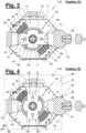
- Figures 3 and 4 illustrate the transition of the rotary switch body (23) from a closed rotary position (S1) to an open rotary position (S2) in a sectional view. They also illustrate a preferred design and arrangement of arcing chambers (32, 33).
- the open rotary position (S2) is preferably provided and fixed at a 90° angle to the closed rotary position (S1). In this way, maximum clear distances between the contact surfaces (28, 29, 30, 31) on the at least one contact blade (24, 25, 26, 27) to the at least one supply connection (20) and the at least one discharge connection (21) are achieved.
- the dimensioning of the contact blades (24, 25, 26, 27) and contact surfaces (28, 29, 30, 31) can be carried out in such a way that the clear width is greater than the minimum distance required for breakdown safety.
- Figure 11 contains a perspective view of an extinguishing chamber (32) with a preferred embodiment.
- the extinguishing chamber (32) is formed by an extinguishing cage, the position of which can be positioned in particular relative to the rotary switch body (23). The positioning can be carried out in particular by adjusting the position and fastening relative to the side walls (15, 16) of an insulator chamber (14) or the switching device (22).
- An extinguishing chamber (32, 33), in particular an extinguishing cage preferably has a plurality of essentially radially to the axis of rotation (A) of the Rotary switch body (23) has quenching plates (34) aligned with the axis of rotation (A).
- the quenching plates (34) can preferably have a matching shape.
- the passage opening (35) preferably overlaps a plurality of contact blades (24, 25, 26, 27) on the rotary switch body (23).
- An quenching cage is thus preferably provided which is designed to quench one or more arcs which can occur between a plurality of contact surfaces on the at least one contact blade (24, 25, 26, 27) and, on the one hand, the supply connection (20) or, on the other hand, the discharge connection (21) when the electrical connection is separated.
- two or more passage openings (35) can be provided.
- one passage opening (35) can be provided for each pair of contact blades (24, 25, 26, 27).
- the quenching plates (34) of a quenching chamber (32, 33) are preferably arranged on a beetle carrier (36).
- This has, as shown in Figures 3, 4 and 11 preferably has two boundary surfaces (37) or boundary walls aligned transversely to the axis of rotation (A). Via these boundary surfaces, the extinguishing cage is preferably in insulating contact with one of the side walls (15, 16).
- the jump drive is preferably designed as a rotary jump drive.
- the movement of the output flange (41) is preferably a rotary movement, in particular an iterative and unidirectional rotary movement.
- the drive flange (43) is moved, for example, by the (electric) drive motor (45) and/or a manual drive (46).
- the movement can be essentially continuous, while the output flange (41) is held either in the closed rotary position (S1) or in the open rotary position (S2).
- the movement of the drive flange (43) can in particular take place until a sufficient amount of energy is contained in the energy storage device (42).
- the sudden switching rotation can then be triggered.
- the triggering can take place immediately when the required charge in the energy storage device (42) is reached. Alternatively, the triggering can take place at a later time.
- the residual load circuit breaker (1) and in particular the snap drive (40) has a triggering means (44) which is designed to trigger or prevent the sudden switching rotation depending on one or more criteria.
- the triggering means (44) can in particular be designed to prevent the sudden switching rotation if the energy accumulator (42) has an insufficient charge or pre-tension.
- load detection can be used to determine whether a safety requirement for manual access to the residual load isolator is met.
- the safety requirement can, for example, stipulate that manual access is only classified as safe if the current load falls below a first permissible limit value, for example a low-voltage limit value of 50V. Alternatively, a different value can be provided for a low-voltage limit value.
- the load detection can alternatively or additionally be designed to determine whether a residual load or a residual current or a main load or a main current is present.
- a residual current or a residual load is preferably detected when the electrical load, in particular the voltage and/or the current flow between the supply connection (20) and the discharge connection (21), is below a (second) permissible limit value.
- the second permissible limit value can, for example, be the limit value that is also used as the permissible limit value for enabling or triggering a switching rotation.
- the second permissible limit value can, in particular, be the residual load limit value and can, for example, be 50 A / 900 V. Alternatively, other values are possible, in particular maximum voltages of up to 1,500 V and/or maximum currents of up to 100 A.
- the second permissible limit value can be a switching load limit value which characterises a maximum permissible electrical load which can be applied during a separation of the electrical connection between the at least one supply connection (20) and at least one discharge connection (21).
- the switching load limit value can differ from the residual load limit value.
- a particularly simple and cost-effective variant of load detection provides that a voltage monitor (92) evaluates a voltage present across the residual load isolating switch (1), in particular between the at least one supply connection (20) and the at least one discharge connection (21). If this voltage is above the first permissible limit value, which is e.g. 50V (low voltage limit value), it is determined that an unsafe state exists, which causes manual access to the residual load isolating switch (1) to be restricted.
- the access restriction can be brought about by any means.
- a first access restriction means can be a display device that provides a warning about the unsafe state. The warning can be provided in any way, e.g. by a text display and/or suitable symbol representations.
- an electrical supply connection to the drive motor (45) can be interrupted during an unsafe condition, for example by a relay contained in the voltage monitor (92) or another suitable switching means.
- a rotation lock can be activated, which enables switching of the at least one rotation switch body (23)
- a rotation lock can be achieved by any means, in particular by a mechanical blocking means.
- a preferred embodiment of a mechanical blocking means provides that a locking bar, a locking pin or similar fixes the at least one rotary switch body (23) and/or the output flange (41) of the spring drive (40) in the direction of rotation relative to a housing part of the residual load disconnector (1).
- the locking bar or locking pin can be actuated, for example, by an electrical switching means such as a solenoid. It can be actuated in particular in an unlocking direction by an elastic preload force and can be displaced in the locking direction by the electrical switching means if or as long as the unsafe state is determined.
- a protective housing (81) of the rotary isolating switch (1) can be locked in a controlled manner if or as long as the unsafe state exists.
- a similar or the same blocking means can be used as was previously explained for blocking the rotation of the rotary switch body (23).
- a controllable lock (98) can be used (cf. Figure 14 ).
- the protective enclosure (81) and other safety aspects are explained below.
- the presence of a main load or a main current is preferably detected when at least one of the aforementioned limit values is exceeded, in particular when a residual load limit value or a switching load limit value is exceeded.
- the exceeding or falling below of an associated preparation limit value is checked, in particular by the load detection of the residual load isolating switch (1).
- the preparation limit value can have a value that is different from the low-voltage limit value or the residual load limit value. In particular, it can be greater than the low-voltage limit value or residual load limit value by a hysteresis threshold value.
- the preparation limit value can be 55 volts, for example, while the low-voltage limit value is 45 volts.
- the aforementioned limit values can be set via a current value or a power value or another suitable parameter for determining a load.
- a case distinction can be made to determine a current load case, whereby the necessary measures for preparing, carrying out and checking a switchover are carried out in staggered time depending on the load case determined. If, for example, a current load of 100 volts is present, it would be determined that the load present is above the low-voltage limit value and above the preparation limit value. This load case can be evaluated as an exclusion load case in which any manual access to the residual load disconnector is denied.
- a momentary load of 40 volts is detected, i.e. generally speaking, a momentary load that is below the extra-low voltage limit and below the preparation limit, it is determined that a release load case exists in which a received request for disconnecting the electrical connection can be implemented directly and manual access to the residual load disconnector can be granted directly.
- a received request to disconnect the electrical connection at the residual load isolating switch (1) can lead to a reaction in two phases, in particular in a preparation phase and in a triggering phase.
- measures can be taken to prepare for a switching movement, the preparation phase preferably having a maximum predetermined time duration.
- the triggering phase the actual switching can take place, i.e. the disconnection or establishment of the electrical connection.
- the subsequently achieved switching state and/or the subsequent current load can be monitored in the triggering phase.
- a transition from the preparation phase to the triggering phase can take place if and when it is determined within the predetermined time duration of the preparation phase that the preparation measures have been completed and the current load (still or in the meantime) falls below a permissible limit value, in particular the residual load limit value or the low voltage limit value.
- the execution of the separation or establishment of an electrical connection can alternatively or additionally be made dependent on an additional external input, in particular on the receipt of an additional separation confirmation or switch-on confirmation.
- the initiation of the preparation phase and/or the completion of the preparation measures and/or the additional undershoot of the permissible limit value and/or the (successful) completion of the triggering phase and/or any error states that may occur can be displayed by one or more status messages on the residual load disconnector (1) and/or communicated by sending the status message(s). This significantly improves the traceability of the status on the residual load disconnector (1) for an operator.
- the disconnection limit value can be a voltage limit value according to the previous examples and/or a current limit value or a power limit value, in particular the low-voltage limit value mentioned above. If the current load falls below the disconnection limit value after the rotary switch body has been switched to the open rotary position, it is determined that the electrical connection between the supply connection (20) and the discharge connection (21) has actually been separated and a safe state has thus been reached.
- Successful completion of the tripping phase can be determined and displayed or communicated if, on the one hand, it is determined that the rotary switch body(s) (23) have reached the open rotary position and, on the other hand, the current load has fallen below the disconnection limit value. If one of these conditions is not met or not met within a specified time interval, an error condition can be detected and displayed or sent as a status message.
- the presence of a main load can be detected by querying a switching state of a (remote) main load disconnector (3), which is explained below.
- the query of the switching state of the main load disconnector (3) is preferably carried out by exchanging data messages, in particular with a (remote) monitoring station (US).
- FIG. 2 shows a power supply for an electrically operated means of transport (7) in a schematic view.
- the electrical means of transport (7) is in this case a train or a suburban train that travels on a track or a section of track (6).
- the electrical means of transport (7) draws its traction current via a current tap (10) from a traction current supply conductor (8), which in this case is designed as a conductor rail.
- the traction current supply conductor (8) is connected to a feed line (4) at a feed point (9) via the residual load isolating switch (1) according to the present disclosure.
- the feed point (9) is thus the supply conductor feed point.
- a load in particular the permissible residual load, can still be present at the feed-in point (9) or the traction current supply conductor (8) for some time even after a main load isolating switch (3) has been opened, which must be electrically separated from the traction current supply conductor (8) by the residual load isolating switch (1) according to the present disclosure.
- monitoring station which is connected for data purposes to the voltage source (2) and/or the main load disconnector (3) and/or the residual load disconnector (1) according to the present disclosure.
- the monitoring station can query the switching state of the main load disconnector or determine in some other way whether the main load is present at the feed-in point (9).
- the triggering means (44) can obtain information from the monitoring station (US) as to whether the main load is present or not and prevent a switching movement of the rotary switch body (23) when the main load is present.
- the design variants of the residual load disconnector (1) shown in the figures are designed to be actuated by the motor drive (45) on the one hand and by a manual drive (46) on the other. Actuation by the motor (45) can take place, for example, as follows: A request to disconnect the electrical connection at the feed-in point (9) is received from an external signal generator. The request can be generated, for example, by the monitoring station (US) or by an actuating device on the track section (6). According to an optional step, the residual load isolating switch (1) and in particular the tripping means (44) checks whether a main load is present.
- the motor (45) is operated to load the spring drive (40) or the energy storage device (42) contained therein, in particular under the condition that it has been determined that there is no main load but at most a residual load.
- a sudden rotary movement is triggered so that the rotary switch body (23) is moved from the closed rotary position (S2) to the open rotary position (S1).
- the sudden rotary movement is triggered when and in particular as soon as the energy storage device (42) has reached the prescribed load.
- the sudden rotary movement is triggered under the condition that a load detection has determined that only the permissible residual load between the at least one supply connection (20) and the at least one discharge connection (21), but not the main load.
- the spring drive (40) can be loaded by actuating the manual drive (46), in particular an iterative movement of a ratchet lever (84).
- the spring movement can be triggered as soon as the prescribed load in the energy accumulator (42) is reached.
- it can be checked that at the time of triggering there is no main load but at most the permissible residual load.
- the triggering means (44) is preferably designed to permit manual and/or motor-induced actuation of the switching device (22) only when the maximum permissible residual load is present.
- the load detection can also be used to make access to the residual load disconnector (1) and in particular to the manual drive (46) or the ratchet lever (84) dependent on the fact that only a permissible residual load is present, but not the main load.
- the manual drive (46) can be designed in any way. In a preferred embodiment, it acts on the drive flange (43) of the spring drive, in particular in mechanical superposition to the drive motor (45). Particularly preferably, the residual load isolating switch (1) and in particular the drive motor (45) or the spring drive (40) have a reduction gear.
- the manual drive (46) can be driven via this reduction gear act on the drive flange (43) of the spring drive (40), so that only minimal manual force is required to load the spring drive (40).
- Any manually grippable instrument can be provided to operate the manual drive. This is preferably a ratchet lever (84) that can be moved back and forth. Alternatively, a hand crank can be provided, which can also (optionally) have a ratchet mechanism.
- a ratchet mechanism has the advantage that the actuating instrument is not moved when the spring drive is actuated by a motor.
- the residual load isolating switch (1) preferably has a position detection means (47) which is designed to detect the rotational position of the at least one rotary switch body (23) or the presence of a closed rotational position (S1) or an open rotational position (S2).
- the position detection means (47) can be designed in any way.
- the position detection means (47) is formed by a cam disk detection.
- a cam disk is arranged on the rotation axis (A) and is connected in a torque-resistant manner to the at least one rotary switch body (23).
- the cam disk has at least one and preferably two cams which actuate one or more contact switches arranged on the circumference of the cam disk.
- a first contact switch is pressed in by a cam, while a second contact switch is not pressed in.
- the second contact switch is in relation arranged on the rotation axis (A) orthogonal to the first contact switch.
- the presence of a closed rotation position (S1) or an open rotation position (S2) is detected here if, according to a known coding, one of the two contact switches is activated and the other contact switch is not activated. If, however, both contact switches are not activated, the rotary switch body (23) is in an intermediate position.
- the position detection means (47) can additionally detect whether the rotary switch body (23) is outside the closed rotary position (S1) and outside the open rotary position (S2) for an inadmissibly long period of time. In such a state, an alarm state can be triggered, which can be communicated to the monitoring station (US), for example. Furthermore, in such a case, manual access to the residual load disconnector can be restricted.
- the residual load disconnector or the at least one rotary switch body (23) preferably has a one-sided limited direction of rotation for carrying out the switching movement(s).
- a right rotation should be provided in order to move the rotary switch body (23) iteratively from a closed rotary position (S1) to an open rotary position (S2) and back to a closed rotary position (S1) etc.
- the preferred unidirectional and cyclical actuation of the rotary switch body (23) makes it particularly easy to control and monitor the residual load isolating switch (1).
- no direction changeover gear and no direction of rotation reversal control are required.
- a single rotary motor (45) that is driven in a single direction of rotation can be used to trigger both the separation of the electrically conductive connection on the residual load isolating switch (1) or the switching device (22) and its restoration.
- the jump drive (40) is therefore preferably designed to trigger iterative jump-like rotary movements in the same direction of rotation at constant angular intervals.
- the angular intervals can in particular be 90 degrees each.
- the rotary switch body (23) can be provided with a two-sided rotational mobility.
- the separation of the electrical connection ie the switching between a closed rotary position (S1) and an open rotary position (S2), in a first predetermined direction of movement and the closing of the electrical connection in the opposite direction, which also means that arcing chambers only have to be provided on the trailing side of the direction of movement specified for the separation.
- a free direction of movement of the rotary switch body (23) can be provided.
- arcing chambers can be provided in both tangentially adjoining areas next to a supply connection (20) and a discharge connection (21).
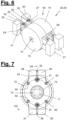
- FIGS 6 to 9 illustrate a preferred embodiment of the switching device (22) or of a rotary switching body (23).
- the rotary switching body (23) has at least one pair and preferably two pairs of contact blades (24, 25, 26, 27). Accordingly, two contact blades (24, 25/26, 27) are arranged parallel and coaxially to the axis of rotation (A).
- a pair of contact blades (24, 25/26, 27) is designed for the joint contacting of a supply connection (20) on the one hand and a discharge connection (21) on the other.
- a contact tongue (51, 52, 53, 54) is provided on the supply connection (20) and the discharge connection (21), which is received in a closed rotational position (S1) between the pair of contact blades (24, 25 / 26, 27) (cf. Fig. 6 ).
- the rotary body (23) preferably has an (insulating) housing (60) which can be made up of one or more parts.
- One or more pairs of contact blades are preferably fixed in the radial direction on or in the housing (60) and mounted with play in the axial direction.
- the tolerance for a (local) mobility of a contact blade in the axial direction can be limited by suitable means.
- a rotational position of the contact blades (24, 25, 26, 27) is clearly determined by the rotational position of the housing (60), while in the axial direction (parallel to the axis of rotation A) the contact blades (24, 25, 26, 27) are movable at least within a predetermined tolerance range in order to be able to move into an optimal contact position with the contact tongues (51, 52, 53, 54).
- the assumption of the optimal contact position during the transition to the closed rotational position (S2) is preferably brought about by a mechanical pre-tension of the contact blades and by run-on bevels on the contact surfaces and/or the contact tongues, which is explained in additional details below.
- At least one axial bearing element (61) and at least one radial bearing element (62) independent of it can be provided on the rotary switch body (23).
- the axial bearing element (61) is designed to accommodate the contact blades (24, 25 / 26, 27) of a pair and to position them relative to one another with axial play and in particular to preload them.
- the Prestressing is directed in particular towards the inside of the pair, ie towards a central plane between the contact blades (24, 25/26, 27) of a pair.
- the pair as a whole can move in the axial direction (parallel to the axis of rotation A), in particular on its own or together with another pair.
- This means that internal mobility of the contact blades (24, 25/26, 27) in a pair and global mobility of the pair or several pairs are preferably provided, each of which can be subject to different tolerances.
- the at least one radial bearing element (62) is designed to fix one or more contact blades and in particular all contact blades (24, 25, 26, 27) of a rotary switch body (23) in the radial direction, i.e. to connect them to the housing (60) in a torque-proof manner.
- the radial bearing element (62) preferably has no bearing effect in the axial direction, i.e. parallel to the axis of rotation (A).
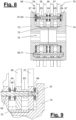
- FIG. 8 Preferred embodiments of an axial bearing element (61) and a radial bearing element (62) are shown in a sectional view.
- the sectional view refers to a section line VIII-VIII in Figure 7 .
- Figure 9 shows an enlarged view of the upper right area of Figure 8 .
- An axial bearing element (61) is formed here by a support bolt (63), at least one spring element (64, 66) and a spacer (65).
- the axial bearing element (61) comprises one or more fastening means (67, 68).
- Mechanical springs, in particular disc springs and disc spring packages, are preferably used as spring elements (64, 66).
- On the support bolt (63) according to the illustration in Figure 8 two tensioned bearing arrangements (69, 70) are formed, each of which supports and pre-tensions a pair of contact blades (24, 25 / 26, 27). Alternatively, only one or any other number of bearing arrangements (69, 70) can be provided on a support bolt (63).
- the bearing arrangement (69, 70) shown comprises a layered arrangement of a first spring element (64), a first contact blade (24), a spacer (65), a second contact blade (25) and optionally a second or further spring element (66) in the axial direction (A).
- a sleeve which is placed on the support bolt serves as a spacer (65) here, for example.
- the bearing arrangement (69, 70) is in the example of figures (8, 9 ) is secured to the inside by a projection of the support bolt, which forms a first fastening means, and to the outside by a screw, which forms a second fastening means (67).
- any other fastening means can be provided, such as snap rings, locking pins, shaft nuts, welded projections, etc.
- the contact blades (24, 25 / 26, 27) in a tensioned bearing arrangement (69, 70) are held in the open rotation position by the one or more spring elements (64, 66). with pre-tension on the spacer (65) located between them.
- the spacer thus provides a minimum clearance between the contact surfaces (28, 29 / 30, 31) of a pair.
- the contact surfaces (28, 29 / 30, 31) come into contact with an associated contact tongue (51, 52, 53, 54), in particular via run-on slopes.
- the minimum clear width between the contact surfaces (28, 29 / 30, 31) is preferably smaller than the width of the associated contact tongue (51, 52, 53, 54), so that the contact blades (24, 25, 26, 27) are moved apart or spread against the preload of the spring elements (64, 66) when sliding on a contact tongue (51, 52, 53, 54).
- the one or more spring elements (64, 66) are elastically compressed so that they continue to maintain the preload force on the contact blades (24, 25, 26, 27) or the contact surfaces (28, 29, 30, 31).
- Each touching contact between a contact tongue (51, 52, 53, 54) and a contact surface (28, 29, 30, 31) forms a contact zone in which the touching contact is preferably held with mechanical prestress.
- a radial bearing element (61) can preferably be formed by a guide pin which is fixed to the rotary switch body (23), in particular the housing (60), in the direction of rotation and at least one contact blade (24, 25, 26, 27) is fixed in the radial direction relative to the rotary body (23).
- the at least one contact blade is preferably on the Guide pin (71) mounted so as to be axially movable.
- the guide pin (71) itself can be fixed to the housing (60) in the axial direction.
- the radial bearing element (61) thus preferably allows both an internal movement of the contact blades in the axial direction among each other, as well as a global movement of the contact blades as a whole relative to the housing (60).
- the axial bearing elements (61) and radial bearing elements (62) can be provided in any number and arrangement on the rotary switch body (23).
- Figure 7 shows a particularly preferred arrangement.
- two axial bearing elements (61) are provided. These are arranged on a common line of symmetry on both sides of the axis of rotation (A) and in spatial proximity to the multiple arrangements of contact surfaces (28, 29/30, 31).
- exactly one axial bearing element (61) is provided in the vicinity of exactly one multiple arrangement of contact surfaces (28, 29/30, 31) and in particular approximately on a center line of the respective multiple arrangement.
- the preload force applied by the axial bearing element (61) and in particular the spring elements (64, 66) is thus distributed essentially evenly over the multiple contact surfaces (28, 29/30, 31) of the respective multiple arrangement.
- radial bearing elements (62) are also provided, which are distributed substantially evenly around the axis of rotation (A) and in the present example penetrate all contact blades (24, 25, 26, 27).
- a A different number and arrangement of radial bearing elements can be provided. Basically, one radial bearing element would be sufficient, whereby a central support of the contact blades (24, 25, 26, 27) can be provided on the housing (60).
- each lateral projection of the contact blades which carries a contact surface (28, 29, 30, 31) has its own elastic mobility within a certain range and, furthermore, each multiple arrangement of contact surfaces has a common mobility.
- the preload which is essentially generated via the spring elements (64, 66), can be distributed essentially evenly over the contact surfaces of the associated multiple arrangement.
- the rotary body (23) and in particular the contact blades (24, 25, 26, 27) preferably have a shape that is rotationally symmetrical to the axis of rotation (A), wherein furthermore preferably the contact tongues (51, 52, 53, 54) are essentially identically shaped and arranged rotationally symmetrically to the axis of rotation (A).
- a contact is made essentially simultaneously in the area of a supply connection (20) and a discharge connection (21).
- each of the contact surfaces (28, 29, 30, 31) and/or the contact tongues (51, 52, 53, 54) run-on slopes can be arranged, which in cooperation with the The axial mobility of the pairs of contact blades and the preload acting in the axial direction on the other hand promote a precise sliding and a safe and vibration-free contact.
- each contact tongue 51, 52, 53, 54
- a contact grease can be applied to the contact tongues (51, 52, 53, 54) and the contact surfaces (28, 29, 30, 31), which promotes relative mobility and electrical contact even over long periods of time.
- the contact surfaces and contact tongues are preferably provided with a soldered or otherwise suitably attached plating made of a highly conductive material, in particular with a soldered silver plating.
- the housing (60) of the rotary body (23) is in the Figures 6 to 9 in a preferred embodiment variant. It is designed as a multi-part insulating housing and comprises a first half-shell (73), a second half-shell (74) and an inner sleeve (72).
- the at least one contact blade (24, 25, 26, 27) has a central ring section, from which the radially extending protruding contact surfaces (28, 29, 30, 31). In the ring section there is a central recess through which the insulating housing (60) preferably extends.
- the contact blades preferably consist of a highly conductive metal, in particular copper, and are formed in one piece.
- the contact blades can be spaced apart from the housing (60) and in particular the inner sleeve. This ensures that a current flowing through the contact blades (24, 25, 26, 27) (main load current or residual current) cannot overflow onto a shaft (11) that is arranged in the center of the rotary switch body (23).
- inwardly directed cylinder sections can be provided on the half shells (73, 74), which pass through the central recesses in the contact blades (24, 25, 26, 27) towards the inside.
- an additional, essentially cylindrical ring-shaped sleeve (72) can be placed on these cylinder sections, which covers a gap between the half shells (73, 74).
- the mounting and shape of the contact blades (24, 25, 26, 27) can be selected such that an air gap remains between the central recess and the cylindrical sleeve or the inwardly directed cylinder sections of the half-shells (73, 74).
- the half shells (73, 74) can also cover the axial outer sides and in some areas the radial outer sides of the contact blades (24, 25, 26, 27), in particular in the areas where there are no outwardly projecting contact surfaces (28, 29, 30, 31)
- the housing (60) preferably envelops all contact blades (24, 25, 26, 27) of the rotary switch body (23) in an insulating manner, with the exception of the contact surfaces (28, 29, 30, 31) projecting in the radial direction.
- a gap between the half shells (73, 74) can be covered by a further insulating element (not shown).
- the aforementioned features of the housing design create particularly long creepage distances that are thus protected against breakdown.
- the housing design thus ensures reliable insulation of the contact blades from the shaft and any adjacent rotary switch body.
- the residual load disconnector according to the present disclosure can preferably have two or more rotary switch bodies (23) which are arranged next to one another in particular in the axial direction (A).
- two or more rotary switch bodies (23) are arranged next to one another in the insulator chamber (14).
- Each of the rotary switch bodies can have two pairs of contact blades or any other number of contact blades, in particular one pair or three pairs, as explained above.
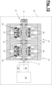
- the residual load isolating switch (1) comprises two (or more) module switching blocks (12, 13). These in turn each comprise its own insulator chamber (14) with at least one supply connection (20), a rotary switch body (23) and at least one discharge connection (21).
- each of the module switching blocks (12, 13) is a switching device (22) according to the present disclosure.
- the plurality of module switching blocks (12, 13) is connected to a common central shaft (11) (cf. Figure 12 ) or a plurality of coupled shafts (not shown).
- the plurality of module switching blocks (12, 13) is preferably connected to a common spring drive (40), which is connected in particular to a first end of the central shaft (11) or a first of the coupled shafts.
- the position detection means (47) is preferably arranged at the other end of the central shaft (11) or the last of the coupled shafts, which can thus detect the common rotational position of all switching bodies (23) via the rotational position of the central shaft (11) or via the common rotational position of the coupled shafts.
- a separate jump drive (40) and/or a separate position detection means (47) can be provided for one, two or more module switching blocks (12, 13).
- the residual load isolating switch (1) preferably has a feed-out collector (19) which is connected to all the discharge connections (21) of the one or more module switching blocks (12, 13) or one or more switching devices (22).
- This feed-out collector (19) can thus collect the main load current or the residual load current as a one-piece component and transmit it to a connection (80) to a traction current supply conductor (8).
- the feed-out collector (19) can also act as a heat sink in relation to the one or more discharge connections (21).
- all the supply connections (20) of the one or more module switching blocks (12, 13) are preferably connected to a common feed-in rail (18), which can also produce a cooling effect.
- the feed-out collector (19) can also serve as a mechanical fastening in order to fix the residual current isolating switch (1) to an external structure and to support it with force. It can in particular act as a common mechanical fastening for a plurality of module switching blocks (12, 13).
- the residual load isolating switch (1) is preferably attached or can be attached to an external support structure (8) via the feed-out collector (19). It can be mounted in particular as shown in Figure 1 be attached directly to a conductor rail (8) or directly to an overhead line (not shown) by means of the connection (80) and be mechanically supported relative to it.
- the residual load isolating switch (1) can be arranged in direct proximity to the traction current supply conductor (8) to be supplied, which on the one hand makes it easier to find and on the other hand makes its function obvious.
- the residual load isolating switch (1) can be arranged directly on a section of track (6) essentially without spatially hindering the operation of the means of transport (7). It is not necessary to provide a separate switch cabinet at the feed-in point (9) or to arrange the residual load isolating switch physically away from the traction current supply conductor (8).
- the aforementioned aspects make it easier for workers who are unfamiliar with the area to operate the residual load isolating switch in an emergency situation.
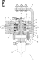
- the residual load disconnector (1) can be housed in a separate protective housing (81) which is Figures 4 and 12 is sketched in outline. Figures 13 and 14 show another preferred embodiment of the protective housing.
- the protective housing (81) can be a possibly removable component of the residual load disconnector (1) and can preferably be provided in addition to the isolator chamber (14), for example in order to encapsulate the residual load disconnector (1) against the ingress of dust or moisture.
- the protective housing (81) can in particular be formed by a protective container (cf. Fig. 13 ).
- the protective housing (81) achieves protection class IP65.
- a particularly preferred embodiment provides that the protective housing (81) is mechanically supported directly or indirectly via the feed-out collector (19), namely via the same external support structure to which the residual load disconnector (1) can be fixed.
- the protective housing (81) is mechanically supported on its underside with a lower Cover (17) of the residual load isolator (1), which in turn is connected to the feed-out collector (19) in a mechanically supporting manner via the isolator chamber (14).
- a force acting on the protective housing (81) from the outside is thus transmitted via the isolator chamber (14) to the feed-out collector (19) and from there to the connection (80).
- the residual load isolating switch (1) can have a weight compensation holder (94). This can be designed in particular in the form of a piece foot or a support arm.
- the weight of the residual load isolating switch (1) can possibly result in an inadmissible deformation of the traction current supply conductor (8) to which the residual load isolating switch (1) is attached.
- further deformation of the supply conductor (8) is possible due to temperature changes and any mechanical influences from the operation of the means of transport.
- the weight compensation holder (94) is preferably designed to allow elastic deformation of the traction current supply conductor (8) and to allow limited mobility or limited movement of the residual current isolating switch (1) and/or the protective housing or the protective container (81).
- the weight compensation holder (94) preferably comprises an elastic support means, for example in the form of a spring.
- the support means can be pre-tensioned. It can be pre-tensioned to such an extent that the weight of the residual load isolating switch (1) and/or the protective container (81) is balanced by the restoring force of the support means. is compensated for predominantly or completely.
- the support means can also be elastically evasive in order to allow the residual load disconnector (1) and/or the protective container (81) to be raised or lowered as a result of external forces.
- the support means preferably has at least one-axis, preferably two-axis, transverse mobility, so that a horizontal evasive movement of the residual load disconnector (1) and/or the protective container (81) is also possible.
- the feed-out collector (19) penetrates the protective housing or the protective container (81) preferably to form a sealing point which in particular seals against the ingress of dust and jet water (cf. Figure 4 ).
- the feed-out collector (19) particularly preferably has a substantially ring-shaped sealing seat (82) and is connected to the protective housing (81) via a circumferential sealing means (83). In this way, the ingress of dust and water or moisture can be effectively prevented.
- no seams are created in the area of the sealing seat (82), which is advantageous for permanent sealing.
- the protective housing (81) can preferably be hinged, for example according to the Figure 4 shown dividing plane (88), which runs essentially obliquely to the horizontal plane.
- An upper part of the The protective housing (81) can be folded away to allow manual access to the manual drive (46) and to the handles (85) arranged at the top of the residual load isolating switch (1).
- the residual load isolating switch (1) When folded open, the residual load isolating switch (1) can thus be grasped directly in order to position and fix it, for example, with a pre-assembled connection (80) on a traction current supply conductor (8).
- the residual load isolating switch (1) can thus be installed together with the protective housing (81), whereby only the fixing points on the connection (80) to the traction current supply conductor (8) and possibly on the feed rail (18) to a feed line (4) need to be attached. Installation and/or replacement can thus be carried out particularly quickly and easily. Due to the fixed combination of residual load isolating switch (1) and protective housing (81), it is also ensured that the liquid and dust-tight connection in accordance with the prescribed protection class is fulfilled after installation. The sealing point between the sealing means (83) and the sealing seat (82) does not have to be touched in order to install or remove the residual load isolating switch (1).
- the feed-out collector (19) is preferably made of a light metal, in particular aluminum. It preferably has a highly electrically conductive coating, in particular a silver coating or silver plating. The coating can be applied on all sides.
- the aforementioned choice of material leads to various advantages.
- the overall weight of the residual load isolator (1) is reduced, so that it can be handled and installed by just one worker.
- aluminum conducts any heat generated at the contact points inside the residual load isolator (1) particularly well to the outside, so that the heat can be dissipated in particular via the connection (80) into the traction current supply conductor (8).
- the silver plating achieves a particularly high level of conductivity, which is maintained even under unfavorable ambient conditions.
- the residual load isolating switch (1) can preferably have an access restriction means which only allows manual access to the residual load isolating switch (1) if a detected electrical load, in particular the detected load between the supply connection (20) and the discharge connection (21), falls below a permissible limit value and/or if it is detected that an upstream main load isolating switch (3) is open.
- the access restriction means can be, for example, a lock or locking mechanism, in particular a controllable lock (98). It can interact with the load detection means described above and/or the triggering means (44) described above.
- the access restriction means preferably ensures that manual access to the residual load isolating switch (1) is only possible if there is no main load at the feed-in point (9) or above the residual load isolating switch (1), but at most the defined residual load, prefers only a momentary load that is less than a low voltage limit.
- the residual load disconnector can have a remote control interface, which preferably enables remote-controlled activation of the drive motor (45) and/or the triggering means (44).
- the remote control interface can be designed as desired.
- the residual load disconnector (1) preferably has a remote monitoring interface which is designed in particular to transmit a switching state or a rotational position of the residual load disconnector (1) or of the rotary switching contact (23).
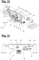
- Figures 13 and 14 show a further preferred embodiment of a residual load isolating switch (1), which here has a protective housing in the form of a protective container (81).
- the residual load isolating switch comprises in the form shown (precisely) a module switching block (12), on or in which an isolator chamber (14) and two rotary switching bodies (23) are arranged.
- the rotary switching bodies are arranged next to one another on a common shaft, which is also connected to the spring drive (40). Otherwise, the design corresponds to that explained above and in Figures 10 to 12 shown variant.
- one or more viewing windows (95) can be provided to allow a view of the switching device (22) and in particular the rotary switching body or bodies (23).
- a current switching position of the rotary switching bodies can be visually read through the viewing window (95).
- the switching position can also be detected by the position detection means (47), which can be seen in the representation of Figure 13 behind the switching device (22).
- the upper part of the protective container (81) is designed as a lid (90). It can be hinged open as explained above.
- the lid can be locked in the closed state, in particular by a controllable lock (98) as explained above.
- An overhang can be formed on at least one side of the cover (90), which protrudes beyond the lower part of the protective container (81) and forms a connection cover (91) for the feed rail (18) and connectors of a supply line (4) attached thereto.
- the feed rail (18) is in the example of Figures 13 and 14 led out laterally from the lower part of the protective container (81).
- the leadthrough is preferably provided with a seal to prevent the penetration of moisture or water into the protective container (81).
- a wired communication interface (92) can be provided on the protective container (81), in particular on its side wall.
- the wired communication interface can be present alternatively or in addition to a wireless communication interface.
- the wireless communication interface is combined with an interface for supplying a general current.
- the general current can be supplied in order to power the electric motor (45) and possibly one or more of the above mentioned control and detection means.
- one or more of the above-mentioned control and detection means can be operated by a current that is conducted via the supply line (4).
- the residual load isolating switch (1) can comprise an energy storage device (battery) which supplies one or more of the above-mentioned control and detection means for a bridging period in the event of a failure of the general power supply and/or the traction current supply.
- the residual load isolating switch (1) can accordingly have one or more charging devices or other suitable charging devices in order to charge the energy storage device from the traction current or the general power.
- the storage capacity of the energy storage device is preferably designed such that the energy storage device, when fully charged, supports at least two, preferably at least six or 10 switching operations of the residual load disconnector as well as a remote monitoring and/or remote control operation for at least 24 hours, preferably at least 72 hours or at least 5 days.
- a software product can be installed or executed on the data processing device (97), which includes instructions for carrying out an operating method according to the present disclosure.
- the software product can be present on a physical data storage device.
- the software product can also be present or stored outside the data processing device, in particular on an external server from which it is temporarily or permanently transferable to the data processing facility.
- a preferred embodiment of the residual current isolating switch (1) provides that access to the residual current isolating switch (1) and in particular its control or detection means is only possible after successful authentication.
- the residual load isolating switch can have any authentication test means for this purpose, which can be designed in particular in the form of a software component and/or in the form of a hardware component.
- an authentication request can be received via one of the communication interfaces (92, 97). This request can be sent from a remote control center or from a mobile device carried by a worker. If the authentication request is confirmed by the authentication test means, remote monitoring access and/or remote control access and/or manual access can be enabled.
- one or more status messages can be transmitted via the residual load isolating switch (1) and/or its control and detection means, including in particular a determined switching position of the at least one rotary switch body (23), a currently applied load and/or a charge state of the jump drive and/or the energy storage device.
- one or more Alarm conditions are transmitted, in particular whether it has been determined that a rotary switch body (23) is in an intermediate position.
- a request to disconnect (or establish) the electrical connection at the residual load disconnector (1) can be processed according to the explained operating procedure.
- the residual load disconnector (1) can still generate and send a warning message if, despite a rejected authentication request, it is determined that the protective housing (81) is opened and/or that the switching state of the residual load disconnector (1) changes.
- the reception and sending of data messages can be carried out in any manner using a wired and/or wireless communication interface (92, 97).
- the data messages can in particular include a request for disconnecting or establishing the electrical connection, a disconnection confirmation or switch-on confirmation, one or more status messages as well as authentication requests and authentication confirmations.
- the residual load disconnector is used to operate an overhead line, it may be particularly advantageous to use a wireless communication interface.
- the residual load disconnector (1) according to the design in Figures 1 to 4 can be designed to conduct a main load of up to 4,000 amperes and/or to disconnect a residual load of up to 900 amperes.
- the residual load disconnector (1) according to the design in Figures 10 to 12 can be designed to conduct a main load of up to 8,000 amperes and/or to isolate a residual load of up to 1,800 amperes.
- By adding further rotary switch bodies (23) and/or module switch blocks (12, 13), the maximum permissible limit values for the main load and the residual load can be changed accordingly.
Landscapes
- Engineering & Computer Science (AREA)
- Mechanical Engineering (AREA)
- Gas-Insulated Switchgears (AREA)
- Driving Mechanisms And Operating Circuits Of Arc-Extinguishing High-Tension Switches (AREA)
- Breakers (AREA)
- Rotary Switch, Piano Key Switch, And Lever Switch (AREA)
Claims (11)
- Disconnecteur de charge résiduelle pour la séparation d'une liaison électrique vers un conducteur d'alimentation en courant de traction (8) pour un moyen de transport (7), le disjoncteur de charge résiduelle (1) comprenant une connexion d'alimentation (20), une connexion de dérivation (21) et au moins un dispositif de commutation (22), dans lequel- Le disconnecteur de charge résiduelle (1)∘ à l'état fermé, fait passer un courant de traction pour le moyen de transport (7) en tant que charge principale, ETo à l'état ouvert, il empêche la transmission d'un courant et notamment de la charge principale- le dispositif de commutation (22) comprend un corps de commutation rotatif (23) avec au moins une lame de contact (24, 25, 26, 27), dans lequel- l'au moins une lame de contact (24, 25, 26, 27) peut tourner autour d'un axe (A) disposé entre le raccord d'alimentation (20) et le raccord de dérivation (21) et présente des surfaces de contact (28, 29, 30, 31) côté extrémité dépassant dans la direction radiale, et où- les surfaces de contact (28, 29, 30, 31) sont en contact avec le raccord d'alimentation (20) d'une part et avec le raccord de décharge (21) d'autre part dans une position de rotation fermée (S1) du corps de commutation rotatif (23) et sont espacées du raccord d'alimentation (20) et du raccord de décharge (21) respectivement dans une position de rotation ouverte (S2) du corps de commutation rotatif (23), etdans lequel- le disconnecteur de charge résiduelle (1) présente un sens de rotation limité d'un côté pour l'exécution des mouvements de commutation et peut être actionné de manière unidirectionnelle et cyclique, afin de déplacer le corps de commutation rotatif (23) en particulier de manière itérative d'une position de rotation fermée (S1) à une position de rotation ouverte (S2) et à nouveau à une position de rotation fermée (S1), etc.
caractérisé en ce que- le disconnecteur de charge résiduelle est prévu et conçu pour couper une liaison électrique avec le conducteur d'alimentation en courant de traction (8), et ce à l'état hors tension OU lorsqu'il existe au maximum une charge résiduelle prédéfinie, qui est présente après la coupure de la charge principale ; et en ce que- le disconnecteur de charge résiduelle présente un entraînement à saut (40) qui est conçu pour amener le corps de commutation rotatif (23) à effectuer une rotation de commutation à saut. - Disjoncteur de charge résiduelle selon la revendication 1, dans lequel le mouvement de rotation complet entre une position de rotation fermée (S1) et une position de rotation ouverte (S2) a lieu en moins de 200 millisecondes.
- Disjoncteur de charge résiduelle selon l'une quelconque des revendications précédentes, dans lequel le disjoncteur de charge résiduelle (1), et en particulier l'actionneur à action brusque (40), comprend un moyen de déclenchement (44) pour déclencher une rotation de commutation de type brusque, et dans lequel- le moyen de déclenchement (44) est conçu pour empêcher la rotation de commutation brusque lorsqu'un accumulateur de force (42) de l'entraînement à action brusque (40) présente une charge ou une précontrainte insuffisante ET/OU lorsque- le disjoncteur de charge résiduelle présente une détection de charge qui surveille un flux de courant et/ou une tension entre la connexion d'alimentation (20) et la connexion de décharge (21) et le disjoncteur de charge résiduelle (1) et en particulier le moyen de déclenchement (44) est conçu pour empêcher un mouvement de commutation du corps de commutation rotatif (23) lorsqu'une charge électrique détectée entre la connexion d'alimentation (20) et la connexion de décharge (21) dépasse une valeur limite d'admissibilité.
- le disconnecteur de charge résiduelle selon l'une des revendications précédentes, dans lequel le disconnecteur de charge résiduelle (1) comporte un moyen de détection de position (47) qui détecte une position de rotation du corps de commutation rotatif (23) ou la présence d'une position de rotation fermée (S1) ou d'une position de rotation ouverte (S2) .
- Disjoncteur de charge résiduelle selon l'une des revendications précédentes, dans lequel le corps de commutation rotatif (23) comporte un boîtier isolant (60) en une ou plusieurs parties, qui comporte notamment une première demi-coque (73), une deuxième demi-coque (74) et un manchon intérieur (72), et dans lequel l'au moins une lame de contact (24, 25, 26, 27) comporte un évidement central à travers lequel s'étend le boîtier (60).
- Disjoncteur de charge résiduelle selon l'une quelconque des revendications précédentes, dans lequel le disjoncteur de charge résiduelle (1- comprend une pluralité de corps de commutation rotatifs (23), qui sont notamment disposés côte à côte dans la direction axiale (A), ET/OU- comprend deux ou plusieurs blocs de commutation modulaires (12, 13), qui comprennent en particulier chacun une chambre d'isolateur (14) avec au moins un raccord d'alimentation (20), au moins ou exactement un corps de commutation rotatif (23) et au moins un raccord de dérivation (21).
- Disjoncteur de charge résiduelle selon l'une des revendications précédentes, dans lequel le disjoncteur de charge résiduelle (1) est logé dans une enceinte de protection (81), notamment un conteneur de protection, et l'enceinte de protection (81) comporte une restriction d'accès qui ne permet un accès manuel au disjoncteur de charge résiduelle que lorsqu'une charge électrique détectée entre la borne d'arrivée (20) et la borne de départ (21) est inférieure à une valeur limite d'admissibilité.
- Disjoncteur de charge résiduelle selon l'une quelconque des revendications précédentes, dans lequel le disjoncteur de charge résiduelle comprend- une interface de commande à distance, ET/OU- une interface de télésurveillance, notamment configurée pour transmettre un état de commutation (S1, S2) du disjoncteur de charge résiduelle (1).
- Procédé de fonctionnement d'un disconnecteur de charge résiduelle (1), le disconnecteur de charge résiduelle (1) étant configuré selon l'une quelconque des revendications précédentes 1 à 8 et comprenant un entraînement rotatif à saut (40) configuré pour amener un corps de commutation rotatif (23) du disconnecteur de charge résiduelle (1) à effectuer une rotation de commutation à saut, caractérisé en ce que le disjoncteur de charge résiduelle (1) a une détection de charge qui surveille un flux de courant et/ou une tension entre la borne d'alimentation (20) et la borne de décharge (21) du disjoncteur de charge résiduelle (1), et dans lequel le procédé de fonctionnement comprend les étapes suivantes:- recevoir une demande de déconnexion électrique au niveau du disconnecteur de charge résiduelle (1) ;- vérifier une charge appliquée au disjoncteur de charge résiduelle entre la borne d'alimentation (20) et la borne de décharge (21) ;- s'il est constaté que la charge appliquée au disconnecteur de charge résiduelle entre la borne d'alimentation (20) et la borne de décharge (21) est inférieure à une charge résiduelle admissible: déclenchement du mouvement de rotation brusque du corps de commutateur rotatif.
- Procédé de fonctionnement selon la revendication précédente, dans lequel le disjoncteur de charge résiduelle (1) comprend un moteur (45) pour charger l'actionneur à action brusque (40) ou un accumulateur d'énergie (42) contenu dans celui-ci, et dans lequel le moteur (45) est actionné uniquement à condition qu'il ait été déterminé que la charge appliquée au disjoncteur de charge résiduelle entre la borne d'alimentation (20) et la borne de décharge (21) est inférieure à la charge résiduelle autorisée.
- Procédé de fonctionnement selon l'une quelconque des revendications 9 à 10, dans lequel le disconnecteur de charge résiduelle (1) comprend un moyen de détection de position (47) configuré pour détecter la position en rotation d'au moins un élément rotatif de charge résiduelle, en particulier la présence d'une position de rotation fermée (S1) ou d'une position de rotation ouverte (S2), et dans lequel la position de rotation du corps de commutation rotatif (23) et/ou la présence d'une position de rotation fermée (S1) ou d'une position de rotation ouverte (S2) est envoyée sous forme de notification d'état via une interface de communication.
Priority Applications (2)
| Application Number | Priority Date | Filing Date | Title |
|---|---|---|---|
| EP23156344.6A EP4212386B1 (fr) | 2017-08-01 | 2018-08-01 | Procédé de fonctionnement pour un disjoncteur-sectionneur |
| EP23156335.4A EP4209385B1 (fr) | 2017-08-01 | 2018-08-01 | Corps de commutation rotatif et sectionneur à charge résiduelle |
Applications Claiming Priority (2)
| Application Number | Priority Date | Filing Date | Title |
|---|---|---|---|
| DE202017104597.8U DE202017104597U1 (de) | 2017-08-01 | 2017-08-01 | Restlast-Trennschalter |
| PCT/EP2018/070880 WO2019025493A1 (fr) | 2017-08-01 | 2018-08-01 | Disjoncteur à charge résiduelle |
Related Child Applications (4)
| Application Number | Title | Priority Date | Filing Date |
|---|---|---|---|
| EP23156344.6A Division EP4212386B1 (fr) | 2017-08-01 | 2018-08-01 | Procédé de fonctionnement pour un disjoncteur-sectionneur |
| EP23156344.6A Division-Into EP4212386B1 (fr) | 2017-08-01 | 2018-08-01 | Procédé de fonctionnement pour un disjoncteur-sectionneur |
| EP23156335.4A Division EP4209385B1 (fr) | 2017-08-01 | 2018-08-01 | Corps de commutation rotatif et sectionneur à charge résiduelle |
| EP23156335.4A Division-Into EP4209385B1 (fr) | 2017-08-01 | 2018-08-01 | Corps de commutation rotatif et sectionneur à charge résiduelle |
Publications (3)
| Publication Number | Publication Date |
|---|---|
| EP3661802A1 EP3661802A1 (fr) | 2020-06-10 |
| EP3661802C0 EP3661802C0 (fr) | 2024-11-20 |
| EP3661802B1 true EP3661802B1 (fr) | 2024-11-20 |
Family
ID=63244551
Family Applications (3)
| Application Number | Title | Priority Date | Filing Date |
|---|---|---|---|
| EP23156344.6A Active EP4212386B1 (fr) | 2017-08-01 | 2018-08-01 | Procédé de fonctionnement pour un disjoncteur-sectionneur |
| EP18755729.3A Active EP3661802B1 (fr) | 2017-08-01 | 2018-08-01 | Disjoncteur à charge résiduelle |
| EP23156335.4A Active EP4209385B1 (fr) | 2017-08-01 | 2018-08-01 | Corps de commutation rotatif et sectionneur à charge résiduelle |
Family Applications Before (1)
| Application Number | Title | Priority Date | Filing Date |
|---|---|---|---|
| EP23156344.6A Active EP4212386B1 (fr) | 2017-08-01 | 2018-08-01 | Procédé de fonctionnement pour un disjoncteur-sectionneur |
Family Applications After (1)
| Application Number | Title | Priority Date | Filing Date |
|---|---|---|---|
| EP23156335.4A Active EP4209385B1 (fr) | 2017-08-01 | 2018-08-01 | Corps de commutation rotatif et sectionneur à charge résiduelle |
Country Status (6)
| Country | Link |
|---|---|
| US (1) | US11139123B2 (fr) |
| EP (3) | EP4212386B1 (fr) |
| JP (1) | JP7222975B2 (fr) |
| CN (1) | CN110944870B (fr) |
| DE (1) | DE202017104597U1 (fr) |
| WO (1) | WO2019025493A1 (fr) |
Families Citing this family (6)
| Publication number | Priority date | Publication date | Assignee | Title |
|---|---|---|---|---|
| CN113199965B (zh) * | 2021-06-17 | 2022-11-25 | 西南交通大学 | 一种与接触网相连的隔离开关引线长度预配方法 |
| KR102416310B1 (ko) * | 2021-10-28 | 2022-07-05 | 동방전기공업(주) | 부하 개폐모듈 및 이를 포함한 부하 개폐장치 |
| GB2627946B (en) * | 2023-03-08 | 2025-04-23 | L C Switchgear Ltd | Isolating switch for electric railway or tramway |
| IT202300004449A1 (it) * | 2023-03-09 | 2024-09-09 | Ntet S P A | Sezionatore elettrico, circuito elettrico comprendente tale sezionatore e procedimento per realizzare tale circuito elettrico. |
| CN116413542B (zh) * | 2023-04-13 | 2024-03-29 | 广东电网有限责任公司佛山供电局 | 一种波动负载下变压器剩余寿命检测装置 |
| CN117116687B (zh) * | 2023-10-25 | 2024-03-08 | 南方电网调峰调频发电有限公司 | 一体化开关操控装置和开关柜 |
Family Cites Families (36)
| Publication number | Priority date | Publication date | Assignee | Title |
|---|---|---|---|---|
| DE1203343B (de) | 1964-02-18 | 1965-10-21 | Krueger K G Maschinenfabrik | Als Streckenschalter fuer elektrische Bahnen geeigneter Trennschalter |
| DE1804661B2 (de) | 1968-10-23 | 1971-10-21 | Hochspannungs dreh lasttrennschalter | |
| DE3230468A1 (de) * | 1982-08-16 | 1984-02-16 | Siemens AG, 1000 Berlin und 8000 München | Verfahren zum betrieb einer elektrischen energieverteilungsanlage |
| US4510360A (en) * | 1983-06-08 | 1985-04-09 | Westinghouse Electric Corp. | Circuit breaker with arc shield |
| DE8423003U1 (de) | 1984-08-02 | 1984-11-15 | Doduco KG Dr. Eugen Dürrwächter, 7530 Pforzheim | Elektrischer Schalter |
| JP2807157B2 (ja) * | 1993-11-04 | 1998-10-08 | 東光電気株式会社 | 高圧気中開閉器 |
| JP3268164B2 (ja) * | 1995-05-16 | 2002-03-25 | 三菱電機株式会社 | 開閉器操作機構 |
| JPH1146436A (ja) * | 1997-07-25 | 1999-02-16 | Toshiba Corp | 自己診断機能付断路器装置 |
| JP4034048B2 (ja) | 2001-06-11 | 2008-01-16 | 矢崎総業株式会社 | 電源制御装置 |
| KR20030058755A (ko) * | 2001-12-31 | 2003-07-07 | 엘지산전 주식회사 | 회로 차단기의 원격 제어장치 |
| JP4409822B2 (ja) | 2002-11-29 | 2010-02-03 | 日本高圧電気株式会社 | ケース入り開閉器 |
| CN2600280Y (zh) * | 2002-12-12 | 2004-01-21 | 成志清 | 铁路10kv自闭贯通电线路远动开关 |
| US6797909B2 (en) * | 2003-02-27 | 2004-09-28 | Mcgraw-Edison Company | High-voltage loadbreak switch with enhanced arc suppression |
| ITMI20032311A1 (it) * | 2003-11-26 | 2005-05-27 | Pfisterer Srl | Sezionatore sotto carico per linee elettriche particolarmente per linee elettriche, per trasporto ferroviario |
| JP2007153255A (ja) * | 2005-12-08 | 2007-06-21 | West Japan Railway Co | レール直流電流検知装置 |
| DE102005060633A1 (de) * | 2005-12-13 | 2007-06-14 | Siemens Ag | Lasttrennschalter für eine gekapselte Schaltanlage |
| DE102006011930B3 (de) * | 2006-03-15 | 2007-02-22 | Cherry Gmbh | Elektrischer Schalter mit einer schwenkbar gelagerten Kontaktwippe |
| CZ2006235A3 (cs) * | 2006-04-07 | 2007-10-17 | Hess Trading Sr, Spol. R. R. O. | Proudový chránic |
| DE202006012002U1 (de) | 2006-08-03 | 2007-12-20 | Walter Kraus Gmbh | Antrieb für einen Schalter in Elektroanlagen |
| KR100817118B1 (ko) * | 2006-10-17 | 2008-03-27 | 엘에스산전 주식회사 | 기중차단기의 가동접촉자 |
| WO2011086433A1 (fr) | 2010-01-18 | 2011-07-21 | Telops Inc. | Procédé de calibration radiométrique pour capteurs infrarouges |
| DE102010033042A1 (de) * | 2010-08-02 | 2012-02-02 | Abb Technology Ag | Antrieb für einen Trennschalter mit C O-Schaltvermögen |
| FI123561B (fi) | 2011-06-07 | 2013-07-15 | Abb Oy | Kytkin |
| KR101250261B1 (ko) | 2011-12-20 | 2013-04-04 | 엘에스산전 주식회사 | 링 메인 유닛의 소호 장치 |
| EP2650893A1 (fr) * | 2012-04-12 | 2013-10-16 | ABB Oy | Appareil de commutation de courant électrique |
| US20130271355A1 (en) | 2012-04-13 | 2013-10-17 | Nokia Corporation | Multi-segment wearable accessory |
| ES2694124T3 (es) * | 2012-06-11 | 2018-12-18 | Abb Oy | Aparato de conmutación de la corriente eléctrica |
| CN104335312B (zh) * | 2012-06-25 | 2017-05-24 | 西门子公司 | 用于中压开关设备的三工位负荷隔离开关 |
| FI125923B (en) | 2012-12-20 | 2016-04-15 | Abb Oy | Moving contact of electronic switch |
| EP2987175B1 (fr) | 2013-04-15 | 2018-02-21 | ABB Oy | Ensemble commutateur électrique |
| DE102014103230B3 (de) * | 2014-03-11 | 2015-06-11 | Fritz Driescher KG Spezialfabrik für Elektrizitätswerksbedarf GmbH & Co | Schaltanlage |
| CN104036977A (zh) * | 2014-07-01 | 2014-09-10 | 上海行创电气有限公司 | 一种可视旋转双断点触头装置 |
| CN204155827U (zh) * | 2014-11-05 | 2015-02-11 | 湖州电力设备成套有限公司 | 一种真空负荷开关 |
| CN204424144U (zh) * | 2015-03-09 | 2015-06-24 | 吴林华 | 隔离开关 |
| CN205376382U (zh) * | 2016-03-04 | 2016-07-06 | 杭州天明电子有限公司 | 一种电除尘器及其隔离开关 |
| CN106887796B (zh) * | 2017-02-21 | 2018-11-02 | 国网山东省电力公司邹城市供电公司 | 安全开关柜 |
-
2017
- 2017-08-01 DE DE202017104597.8U patent/DE202017104597U1/de active Active
-
2018
- 2018-08-01 WO PCT/EP2018/070880 patent/WO2019025493A1/fr not_active Ceased
- 2018-08-01 EP EP23156344.6A patent/EP4212386B1/fr active Active
- 2018-08-01 US US16/635,268 patent/US11139123B2/en active Active
- 2018-08-01 EP EP18755729.3A patent/EP3661802B1/fr active Active
- 2018-08-01 EP EP23156335.4A patent/EP4209385B1/fr active Active
- 2018-08-01 JP JP2020505245A patent/JP7222975B2/ja active Active
- 2018-08-01 CN CN201880049208.9A patent/CN110944870B/zh active Active
Also Published As
| Publication number | Publication date |
|---|---|
| JP7222975B2 (ja) | 2023-02-15 |
| DE202017104597U1 (de) | 2018-11-13 |
| CN110944870A (zh) | 2020-03-31 |
| EP3661802A1 (fr) | 2020-06-10 |
| US11139123B2 (en) | 2021-10-05 |
| EP3661802C0 (fr) | 2024-11-20 |
| CN110944870B (zh) | 2023-11-03 |
| JP2020529707A (ja) | 2020-10-08 |
| EP4209385A1 (fr) | 2023-07-12 |
| EP4212386B1 (fr) | 2026-01-28 |
| EP4212386A1 (fr) | 2023-07-19 |
| EP4209385C0 (fr) | 2025-05-21 |
| WO2019025493A1 (fr) | 2019-02-07 |
| EP4209385B1 (fr) | 2025-05-21 |
| US20200373096A1 (en) | 2020-11-26 |
Similar Documents
| Publication | Publication Date | Title |
|---|---|---|
| EP3661802B1 (fr) | Disjoncteur à charge résiduelle | |
| DE69836300T2 (de) | Vakuumschalter und diese verwendende Vakuumschaltanlage | |
| EP2845213B1 (fr) | Sectionneur à coupure sous charge à trois positions pour installations électriques moyenne tension | |
| EP2048679A1 (fr) | Agencement de sectionneur à coupure en charge | |
| DE2818914A1 (de) | Schalterkombination fuer sammelschienenanlagen | |
| WO2008028724A1 (fr) | Parafoudre comprenant un boîtier et au moins un élément de dérivation | |
| DE102007033704B4 (de) | Anordnung mit einem Lasttrennschalter und einem Erdungsschalter | |
| EP2789000B1 (fr) | Appareil de commutation, en particulier interrupteur sectionneur, pour installations de commutation moyenne tension | |
| EP1961027B1 (fr) | Sectionneur de charge pour poste de commutation blinde, et systeme d'aimant permanent pour sectionneur de charge | |
| EP3535771B1 (fr) | Sectionneur de puissance, dispositif de coupure pourvu d'un sectionneur de puissance, procédé de fonctionnement d'un dispositif de coupure et utilisation d'un sectionneur de puissance | |
| DE102014201809A1 (de) | Erdungsschalter für Bahnstromanlagen und Verfahren zum Erden eines Teils einer Bahnstromanlage mittels eines Erdungsschalters | |
| AT512813A1 (de) | Vorrichtung für einen Trennschalter | |
| WO2023046826A1 (fr) | Connecteur électrique doté d'un dispositif de sécurité et ensemble équipé d'un tel connecteur électrique | |
| CH653472A5 (de) | Trennschalteranordnung. | |
| EP2036178B1 (fr) | Disjoncteur de puissance muni d'un boîtier | |
| DE102006057529B4 (de) | Kontrollvorrichtung, Energieversorgungssystem und Verfahren | |
| EP3559969A1 (fr) | Dispositif de commutation comportant deux sectionneurs et un sectionneur de puissance | |
| EP2810288A1 (fr) | Appareil de commutation, en particulier sectionneur à coupure en charge | |
| DE19712346A1 (de) | Vorrichtung für die Blockierung der Drehung einer Welle eines elektrischen Antriebs für einen bewegten Kontakt eines Schaltgeräts | |
| EP4525218A1 (fr) | Système de connecteur et système de distribution d'énergie électrique | |
| DE202007017015U1 (de) | Kontrollvorrichtung und Energieversorgungssystem | |
| DE3246210A1 (de) | Schnellschalteinrichtung fuer sicherungslasttrenner | |
| DE1138454B (de) | UEberwachungseinrichtung fuer Hochspannungsschaltanlagen mit zwischen den offenen Trennern angeordneten Isolierschutzplatten | |
| DE102014223998A1 (de) | Kompaktleistungsschalter | |
| DEC0007054MA (fr) |
Legal Events
| Date | Code | Title | Description |
|---|---|---|---|
| STAA | Information on the status of an ep patent application or granted ep patent |
Free format text: STATUS: UNKNOWN |
|
| STAA | Information on the status of an ep patent application or granted ep patent |
Free format text: STATUS: THE INTERNATIONAL PUBLICATION HAS BEEN MADE |
|
| PUAI | Public reference made under article 153(3) epc to a published international application that has entered the european phase |
Free format text: ORIGINAL CODE: 0009012 |
|
| STAA | Information on the status of an ep patent application or granted ep patent |
Free format text: STATUS: REQUEST FOR EXAMINATION WAS MADE |
|
| 17P | Request for examination filed |
Effective date: 20200221 |
|
| AK | Designated contracting states |
Kind code of ref document: A1 Designated state(s): AL AT BE BG CH CY CZ DE DK EE ES FI FR GB GR HR HU IE IS IT LI LT LU LV MC MK MT NL NO PL PT RO RS SE SI SK SM TR |
|
| AX | Request for extension of the european patent |
Extension state: BA ME |
|
| DAV | Request for validation of the european patent (deleted) | ||
| DAX | Request for extension of the european patent (deleted) | ||
| STAA | Information on the status of an ep patent application or granted ep patent |
Free format text: STATUS: EXAMINATION IS IN PROGRESS |
|
| 17Q | First examination report despatched |
Effective date: 20221017 |
|
| GRAP | Despatch of communication of intention to grant a patent |
Free format text: ORIGINAL CODE: EPIDOSNIGR1 |
|
| STAA | Information on the status of an ep patent application or granted ep patent |
Free format text: STATUS: GRANT OF PATENT IS INTENDED |
|
| GRAJ | Information related to disapproval of communication of intention to grant by the applicant or resumption of examination proceedings by the epo deleted |
Free format text: ORIGINAL CODE: EPIDOSDIGR1 |
|
| STAA | Information on the status of an ep patent application or granted ep patent |
Free format text: STATUS: EXAMINATION IS IN PROGRESS |
|
| INTG | Intention to grant announced |
Effective date: 20240712 |
|
| INTC | Intention to grant announced (deleted) | ||
| GRAP | Despatch of communication of intention to grant a patent |
Free format text: ORIGINAL CODE: EPIDOSNIGR1 |
|
| STAA | Information on the status of an ep patent application or granted ep patent |
Free format text: STATUS: GRANT OF PATENT IS INTENDED |
|
| GRAS | Grant fee paid |
Free format text: ORIGINAL CODE: EPIDOSNIGR3 |
|
| GRAA | (expected) grant |
Free format text: ORIGINAL CODE: 0009210 |
|
| STAA | Information on the status of an ep patent application or granted ep patent |
Free format text: STATUS: THE PATENT HAS BEEN GRANTED |
|
| INTG | Intention to grant announced |
Effective date: 20241002 |
|
| AK | Designated contracting states |
Kind code of ref document: B1 Designated state(s): AL AT BE BG CH CY CZ DE DK EE ES FI FR GB GR HR HU IE IS IT LI LT LU LV MC MK MT NL NO PL PT RO RS SE SI SK SM TR |
|
| REG | Reference to a national code |
Ref country code: GB Ref legal event code: FG4D Free format text: NOT ENGLISH |
|
| REG | Reference to a national code |
Ref country code: CH Ref legal event code: EP |
|
| REG | Reference to a national code |
Ref country code: DE Ref legal event code: R096 Ref document number: 502018015345 Country of ref document: DE |
|
| REG | Reference to a national code |
Ref country code: IE Ref legal event code: FG4D Free format text: LANGUAGE OF EP DOCUMENT: GERMAN |
|
| U01 | Request for unitary effect filed |
Effective date: 20241211 |
|
| U07 | Unitary effect registered |
Designated state(s): AT BE BG DE DK EE FI FR IT LT LU LV MT NL PT RO SE SI Effective date: 20241220 |
|
| PG25 | Lapsed in a contracting state [announced via postgrant information from national office to epo] |
Ref country code: IS Free format text: LAPSE BECAUSE OF FAILURE TO SUBMIT A TRANSLATION OF THE DESCRIPTION OR TO PAY THE FEE WITHIN THE PRESCRIBED TIME-LIMIT Effective date: 20250320 Ref country code: HR Free format text: LAPSE BECAUSE OF FAILURE TO SUBMIT A TRANSLATION OF THE DESCRIPTION OR TO PAY THE FEE WITHIN THE PRESCRIBED TIME-LIMIT Effective date: 20241120 |
|
| PG25 | Lapsed in a contracting state [announced via postgrant information from national office to epo] |
Ref country code: ES Free format text: LAPSE BECAUSE OF FAILURE TO SUBMIT A TRANSLATION OF THE DESCRIPTION OR TO PAY THE FEE WITHIN THE PRESCRIBED TIME-LIMIT Effective date: 20241120 |
|
| PG25 | Lapsed in a contracting state [announced via postgrant information from national office to epo] |
Ref country code: NO Free format text: LAPSE BECAUSE OF FAILURE TO SUBMIT A TRANSLATION OF THE DESCRIPTION OR TO PAY THE FEE WITHIN THE PRESCRIBED TIME-LIMIT Effective date: 20250220 |
|
| PG25 | Lapsed in a contracting state [announced via postgrant information from national office to epo] |
Ref country code: GR Free format text: LAPSE BECAUSE OF FAILURE TO SUBMIT A TRANSLATION OF THE DESCRIPTION OR TO PAY THE FEE WITHIN THE PRESCRIBED TIME-LIMIT Effective date: 20250221 |
|
| PG25 | Lapsed in a contracting state [announced via postgrant information from national office to epo] |
Ref country code: PL Free format text: LAPSE BECAUSE OF FAILURE TO SUBMIT A TRANSLATION OF THE DESCRIPTION OR TO PAY THE FEE WITHIN THE PRESCRIBED TIME-LIMIT Effective date: 20241120 |
|
| PG25 | Lapsed in a contracting state [announced via postgrant information from national office to epo] |
Ref country code: RS Free format text: LAPSE BECAUSE OF FAILURE TO SUBMIT A TRANSLATION OF THE DESCRIPTION OR TO PAY THE FEE WITHIN THE PRESCRIBED TIME-LIMIT Effective date: 20250220 |
|
| PG25 | Lapsed in a contracting state [announced via postgrant information from national office to epo] |
Ref country code: SM Free format text: LAPSE BECAUSE OF FAILURE TO SUBMIT A TRANSLATION OF THE DESCRIPTION OR TO PAY THE FEE WITHIN THE PRESCRIBED TIME-LIMIT Effective date: 20241120 |
|
| PG25 | Lapsed in a contracting state [announced via postgrant information from national office to epo] |
Ref country code: SK Free format text: LAPSE BECAUSE OF FAILURE TO SUBMIT A TRANSLATION OF THE DESCRIPTION OR TO PAY THE FEE WITHIN THE PRESCRIBED TIME-LIMIT Effective date: 20241120 |
|
| PG25 | Lapsed in a contracting state [announced via postgrant information from national office to epo] |
Ref country code: CZ Free format text: LAPSE BECAUSE OF FAILURE TO SUBMIT A TRANSLATION OF THE DESCRIPTION OR TO PAY THE FEE WITHIN THE PRESCRIBED TIME-LIMIT Effective date: 20241120 |
|
| PLBE | No opposition filed within time limit |
Free format text: ORIGINAL CODE: 0009261 |
|
| STAA | Information on the status of an ep patent application or granted ep patent |
Free format text: STATUS: NO OPPOSITION FILED WITHIN TIME LIMIT |
|
| U20 | Renewal fee for the european patent with unitary effect paid |
Year of fee payment: 8 Effective date: 20250826 |
|
| 26N | No opposition filed |
Effective date: 20250821 |