EP3659480B1 - Befestigungsvorrichtung für sanitärzusatzbauteile sowie verfahren zur befestigung von sanitärzusatzbauteilen - Google Patents
Befestigungsvorrichtung für sanitärzusatzbauteile sowie verfahren zur befestigung von sanitärzusatzbauteilen Download PDFInfo
- Publication number
- EP3659480B1 EP3659480B1 EP19210453.7A EP19210453A EP3659480B1 EP 3659480 B1 EP3659480 B1 EP 3659480B1 EP 19210453 A EP19210453 A EP 19210453A EP 3659480 B1 EP3659480 B1 EP 3659480B1
- Authority
- EP
- European Patent Office
- Prior art keywords
- piston
- vacuum
- fastening
- retaining device
- holding device
- Prior art date
- Legal status (The legal status is an assumption and is not a legal conclusion. Google has not performed a legal analysis and makes no representation as to the accuracy of the status listed.)
- Active
Links
- 238000000034 method Methods 0.000 title claims description 14
- 238000007789 sealing Methods 0.000 claims description 42
- 238000000605 extraction Methods 0.000 claims 5
- 238000007373 indentation Methods 0.000 claims 2
- 238000013022 venting Methods 0.000 description 4
- 241000050051 Chelone glabra Species 0.000 description 1
- 239000012080 ambient air Substances 0.000 description 1
- 238000004891 communication Methods 0.000 description 1
- 238000006073 displacement reaction Methods 0.000 description 1
- 238000005553 drilling Methods 0.000 description 1
- 239000000499 gel Substances 0.000 description 1
- 230000000284 resting effect Effects 0.000 description 1
- 239000002453 shampoo Substances 0.000 description 1
Images


Classifications
-
- F—MECHANICAL ENGINEERING; LIGHTING; HEATING; WEAPONS; BLASTING
- F04—POSITIVE - DISPLACEMENT MACHINES FOR LIQUIDS; PUMPS FOR LIQUIDS OR ELASTIC FLUIDS
- F04B—POSITIVE-DISPLACEMENT MACHINES FOR LIQUIDS; PUMPS
- F04B37/00—Pumps having pertinent characteristics not provided for in, or of interest apart from, groups F04B25/00 - F04B35/00
- F04B37/10—Pumps having pertinent characteristics not provided for in, or of interest apart from, groups F04B25/00 - F04B35/00 for special use
- F04B37/14—Pumps having pertinent characteristics not provided for in, or of interest apart from, groups F04B25/00 - F04B35/00 for special use to obtain high vacuum
-
- A—HUMAN NECESSITIES
- A47—FURNITURE; DOMESTIC ARTICLES OR APPLIANCES; COFFEE MILLS; SPICE MILLS; SUCTION CLEANERS IN GENERAL
- A47K—SANITARY EQUIPMENT NOT OTHERWISE PROVIDED FOR; TOILET ACCESSORIES
- A47K10/00—Body-drying implements; Toilet paper; Holders therefor
- A47K10/12—Grips, hooks, or the like for hanging-up towels
-
- B—PERFORMING OPERATIONS; TRANSPORTING
- B25—HAND TOOLS; PORTABLE POWER-DRIVEN TOOLS; MANIPULATORS
- B25B—TOOLS OR BENCH DEVICES NOT OTHERWISE PROVIDED FOR, FOR FASTENING, CONNECTING, DISENGAGING OR HOLDING
- B25B11/00—Work holders not covered by any preceding group in the subclass, e.g. magnetic work holders, vacuum work holders
- B25B11/005—Vacuum work holders
- B25B11/007—Vacuum work holders portable, e.g. handheld
-
- E—FIXED CONSTRUCTIONS
- E03—WATER SUPPLY; SEWERAGE
- E03D—WATER-CLOSETS OR URINALS WITH FLUSHING DEVICES; FLUSHING VALVES THEREFOR
- E03D9/00—Sanitary or other accessories for lavatories ; Devices for cleaning or disinfecting the toilet room or the toilet bowl; Devices for eliminating smells
-
- F—MECHANICAL ENGINEERING; LIGHTING; HEATING; WEAPONS; BLASTING
- F04—POSITIVE - DISPLACEMENT MACHINES FOR LIQUIDS; PUMPS FOR LIQUIDS OR ELASTIC FLUIDS
- F04B—POSITIVE-DISPLACEMENT MACHINES FOR LIQUIDS; PUMPS
- F04B33/00—Pumps actuated by muscle power, e.g. for inflating
-
- F—MECHANICAL ENGINEERING; LIGHTING; HEATING; WEAPONS; BLASTING
- F04—POSITIVE - DISPLACEMENT MACHINES FOR LIQUIDS; PUMPS FOR LIQUIDS OR ELASTIC FLUIDS
- F04B—POSITIVE-DISPLACEMENT MACHINES FOR LIQUIDS; PUMPS
- F04B39/00—Component parts, details, or accessories, of pumps or pumping systems specially adapted for elastic fluids, not otherwise provided for in, or of interest apart from, groups F04B25/00 - F04B37/00
- F04B39/0005—Component parts, details, or accessories, of pumps or pumping systems specially adapted for elastic fluids, not otherwise provided for in, or of interest apart from, groups F04B25/00 - F04B37/00 adaptations of pistons
- F04B39/0022—Component parts, details, or accessories, of pumps or pumping systems specially adapted for elastic fluids, not otherwise provided for in, or of interest apart from, groups F04B25/00 - F04B37/00 adaptations of pistons piston rods
-
- F—MECHANICAL ENGINEERING; LIGHTING; HEATING; WEAPONS; BLASTING
- F04—POSITIVE - DISPLACEMENT MACHINES FOR LIQUIDS; PUMPS FOR LIQUIDS OR ELASTIC FLUIDS
- F04B—POSITIVE-DISPLACEMENT MACHINES FOR LIQUIDS; PUMPS
- F04B53/00—Component parts, details or accessories not provided for in, or of interest apart from, groups F04B1/00 - F04B23/00 or F04B39/00 - F04B47/00
- F04B53/14—Pistons, piston-rods or piston-rod connections
- F04B53/143—Sealing provided on the piston
-
- F—MECHANICAL ENGINEERING; LIGHTING; HEATING; WEAPONS; BLASTING
- F04—POSITIVE - DISPLACEMENT MACHINES FOR LIQUIDS; PUMPS FOR LIQUIDS OR ELASTIC FLUIDS
- F04B—POSITIVE-DISPLACEMENT MACHINES FOR LIQUIDS; PUMPS
- F04B53/00—Component parts, details or accessories not provided for in, or of interest apart from, groups F04B1/00 - F04B23/00 or F04B39/00 - F04B47/00
- F04B53/14—Pistons, piston-rods or piston-rod connections
- F04B53/144—Adaptation of piston-rods
- F04B53/146—Piston-rod guiding arrangements
-
- A—HUMAN NECESSITIES
- A47—FURNITURE; DOMESTIC ARTICLES OR APPLIANCES; COFFEE MILLS; SPICE MILLS; SUCTION CLEANERS IN GENERAL
- A47K—SANITARY EQUIPMENT NOT OTHERWISE PROVIDED FOR; TOILET ACCESSORIES
- A47K1/00—Wash-stands; Appurtenances therefor
- A47K1/08—Accessories for toilet tables, e.g. glass plates, supports therefor
- A47K1/09—Holders for drinking glasses, tooth brushes, hair brushes, or the like
-
- A—HUMAN NECESSITIES
- A47—FURNITURE; DOMESTIC ARTICLES OR APPLIANCES; COFFEE MILLS; SPICE MILLS; SUCTION CLEANERS IN GENERAL
- A47K—SANITARY EQUIPMENT NOT OTHERWISE PROVIDED FOR; TOILET ACCESSORIES
- A47K2201/00—Details of connections of bathroom accessories, e.g. fixing soap or towel holder to a wall
- A47K2201/02—Connections to a wall mounted support
-
- A—HUMAN NECESSITIES
- A47—FURNITURE; DOMESTIC ARTICLES OR APPLIANCES; COFFEE MILLS; SPICE MILLS; SUCTION CLEANERS IN GENERAL
- A47K—SANITARY EQUIPMENT NOT OTHERWISE PROVIDED FOR; TOILET ACCESSORIES
- A47K5/00—Holders or dispensers for soap, toothpaste, or the like
Definitions
- the invention initially relates to a fastening device for additional sanitary components on a contact surface, such as a wall, with a holding device and a device for generating a negative pressure, the holding device forming a base which has a valve and a contact surface-side vacuum chamber, and the device for generating the negative pressure is provided with a vacuum cylinder, which forms a sealing surface on the side facing the holding device, and in which a suction piston is guided with a sealing element facing the holding device, the vacuum cylinder forming a pull-out lock on the side facing away from the holding device.
- Such a fastening device known from the prior art, which can be documented in printed form, is for example in FIG DE 20 2017 100 097 U1 disclosed. Since the vacuum is generated in several stages, holes in the vacuum cylinder that are close to the pull-out lock are passed over for the venting process so that the suction process can then be repeated.
- the object of the invention is therefore to create an alternative solution which is ergonomically advantageous to handle and has a simple structure.
- the solution according to the invention has the essential advantage that the suction piston is locked in its maximum starting position on the vacuum cylinder and can be released from the holding device by means of a large lever arm and reduced expenditure of force.
- the valve is closed suddenly and the vacuum chamber is sealed by it.
- the pull-out lock it is also possible for the pull-out lock to form four recesses for receiving one rib each.
- the suction piston forms a sealing element with two annular recesses facing the holding device, a piston sealing ring being arranged in each of the two annular recesses of the sealing element and serving to hermetically seal the suction piston against the vacuum cylinder.
- an ergonomic piston handle is arranged on the end of the suction piston.
- the advantage of this method according to the invention consists in particular in the simplified handling and the reduction of the force required by means of a large lever arm when removing the device for generating the negative pressure from the holding device in order to trigger the venting process of the vacuum cylinder and then to repeat the suction process.
- the fastening device is designated as a whole by the reference number 10.
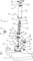
- the Fig. 1 shows the fastening device 10 according to the invention for additional sanitary components.
- the fastening device 10 has a holding device 11 and a device for generating a negative pressure 12.
- the holding device 11 consists of a circular section 13 and an L-shaped section 14, this end having a rectangular fastening opening 15 which is provided with a guide groove 16.
- the fastening opening 15 serves to receive a functional component B, which is designed here as a hook part 17 and is provided with an extension piece 18 which has a guide rib 19.
- the guide rib 19 interacts positively with the guide groove 16.
- the hook part 17 is then fastened to the holding device 11 by means of a screw 20.
- the hook part 17 is used, for example, to hang towels, bathrobes or clothes hooks. It is also conceivable here that the functional component B is designed as a ring-shaped towel holder, toilet roll holder, toothbrush cup holder or as a sanitary shelf for hygiene articles such as shampoos or shower gels. However, other forms and possible uses are also conceivable.
- the holding device 11 On the side facing the contact surface W, the holding device 11 forms a cavity which has the function of a vacuum chamber K and into which a sealing ring 22 is inserted in order to seal the vacuum chamber K from the contact surface W.
- the circular section 13 From the side facing away from the contact surface W, the circular section 13 forms a projection S which is provided with a central bore 21 which is in communication with the vacuum chamber K.
- a one-piece valve 23 which consists of a ball seal 24 and a pin 25, which are fixed by a conical spring 26 and an elastic disc 27.
- the valve 23 suddenly seals the vacuum chamber K as soon as the device for generating a vacuum 12 is detached from the holding device 11.
- a multi-stage, elastic sealing ring 28 is arranged on the circular section 13. This consists of a disk E and a dome-like extension D, which forms two spaced-apart sealing rings R and is used for the sealing arrangement of the device for generating the negative pressure 12.
- the elastic sealing ring 28 is arranged on the projection S when it is abutted on the circular portion 13. 21.
- the device for generating the negative pressure 12 consists of a negative pressure cylinder 29 and a suction piston 30.
- the vacuum cylinder 29 On the side facing the holding device 11, the vacuum cylinder 29 forms a sealing component A, which is provided with a sealing surface 33 and a sealing ring (not shown) resting on the inner circumferential surface.
- the sealing surface is located 33 on the disk E of the sealing ring 28 and the sealing ring (not shown) of the vacuum cylinder 29 is jammed between the sealing rings R which are spaced apart.
- the vacuum cylinder 29 On the side facing away from the holding device 11, the vacuum cylinder 29 has a pull-out lock 31, which forms part of the cylinder cross-section and has four recesses 32.
- the suction piston 30 forms ribs 34 which are arranged at 90 ° in the longitudinal direction and which are positively guided in the recesses 32 of the lock 31.
- the suction piston 30 also has a multi-stage sealing element 35 on the side facing the holding device 11, which forms three sealing disks C with spaced-apart recesses 36 arranged between them, which each serve to receive a piston sealing ring 37.
- This multi-stage sealing element 35 serves to hermetically seal the suction piston 30 on the vacuum cylinder 29.
- a free space F is formed, which in detail in the Figures 5b and 6b is shown and its function will be explained later.
- the suction piston 30 On the side facing away from the holding device 11, the suction piston 30 forms a fastening extension 38 on which a piston handle 39 is arranged.
- a cover cap 40 which, after the holding device 11 has been fastened to the contact surface W, serves to cover the elastic sealing ring 28 and the extension D in a visually attractive manner.
- the Figures 2 to 6 show the pressing and suction process of the device for generating a negative pressure 12 on the holding device 11 for producing the negative pressure in the negative pressure chamber K.
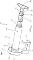
- FIG. 2 the holding device 11 with arranged hook part 17 and the device for generating a negative pressure 12 before it is deposited on the holding device 11, which is illustrated by the arrow direction P.
- the suction piston 30 is in the minimum Pull-out position within the vacuum cylinder 29, the recesses 32 of the pull-out lock 31 of the vacuum cylinder 29 interacting with the ribs 34 of the suction piston 29.
- the device for generating a negative pressure 12 is pressed against the disk E of the sealing ring 28 in the direction of arrow P by means of the sealing surface 33, the suction piston 30 still being in the minimum starting position.
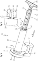
- FIG 5a shows the suction piston 30 in its maximum, unlocked pulled-out position.
- the forced guidance of the ribs 34 in the recesses 32 is canceled and the free space F can be clearly seen ( Figure 5b ).
- the vacuum is now completely generated in the vacuum cylinder 29 and the vacuum chamber K (not shown).
- the suction piston 30 is shown in the maximum, locked, extended position.
- the removal of the forced guidance of the ribs 34 in the recesses 32 enables the rotary displacement of the suction piston 30 by means of the piston handle 39 in the vacuum cylinder 29.
- the Figure 6b shows the locking of the suction piston 30 in the vacuum cylinder 29.
- the ribs 34 are clamped on the outside 41 of the vacuum cylinder 29, whereby the suction piston 30 is fixed on the vacuum cylinder 29 in the maximum extended position.
- FIG. 7 the venting process of the fastening device 10 is shown.
- the device for generating the negative pressure 12 is through a pivoting movement (see arrow direction P) is levered off the elastic sealing ring 28 of the holding device 11, whereby ambient air suddenly flows into the vacuum cylinder 29 and the vacuum in the vacuum cylinder 29 is canceled.
- the valve 23 is closed abruptly at the same time and the vacuum chamber K is thus sealed. The suction process can now be repeated.
Landscapes
- Engineering & Computer Science (AREA)
- Mechanical Engineering (AREA)
- General Engineering & Computer Science (AREA)
- Health & Medical Sciences (AREA)
- Public Health (AREA)
- Epidemiology (AREA)
- Life Sciences & Earth Sciences (AREA)
- Hydrology & Water Resources (AREA)
- Water Supply & Treatment (AREA)
- Hooks, Suction Cups, And Attachment By Adhesive Means (AREA)
Description
- Die Erfindung betrifft zunächst eine Befestigungsvorrichtung für Sanitärzusatzbauteile an einer Anlagefläche, wie einer Wand, mit einer Halteeinrichtung und einer Einrichtung zur Erzeugung eines Unterdrucks, wobei die Halteeinrichtung einen Sockel ausbildet, welche ein Ventil und eine anlageflächenseitige Unterdruckkammer aufweist, und die Einrichtung zur Erzeugung des Unterdrucks mit einem Unterdruckzylinder versehen ist, welche auf der zur Halteeinrichtung gerichteten Seite eine Dichtfläche ausbildet, und in welchem ein Saugkolben mit einem zur Halteeinrichtung weisenden Dichtungselement geführt ist, wobei der Unterdruckzylinder auf der zur Halteeinrichtung abgewandten Seite eine Auszugssperre ausbildet.
- Eine derartige aus dem druckschriftlich belegbaren Stand der Technik bekannte Befestigungsvorrichtung ist beispielsweise in der
DE 20 2017 100 097 U1 offenbart. Da die Erzeugung des Unterdrucks mehrstufig erfolgt, werden für den Entlüftungsvorgang auszugsperrennah ausgebildete Löcher im Unterdruckzylinder überfahren, um anschließend den Saugprozess wiederholen zu können. - Ausgehend von dem Stand der Technik besteht die Aufgabe der Erfindung deshalb darin, eine alternative Lösung zu schaffen, welche ergonomisch vorteilhaft handhabbar und einfach aufgebaut ist.
- Die Lösung der Aufgabe ergibt sich aus den Merkmalen des folgenden Anspruchs 1:
Befestigungsvorrichtung für Sanitärzusatzbauteile an einer Anlagefläche, wie einer Wand, mit einer Halteeinrichtung und einer Einrichtung zur Erzeugung eines Unterdrucks, wobei die Halteeinrichtung einen Sockel ausbildet, welcher ein Ventil und eine anlageflächenseitige Unterdruckkammer aufweist, und die Einrichtung zur Erzeugung des Unterdrucks mit einem Unterdruckzylinder versehen ist, welcher auf der zur Halteeinrichtung gerichteten Seite eine Dichtfläche ausbildet und in welchem ein Saugkolben mit einem zur Halteeinrichtung weisenden Dichtungselement geführt ist, wobei der Unterdruckzylinder auf der zur Halteeinrichtung abgewandten Seite eine Auszugsperre ausbildet, dadurch gekennzeichnet, dass die Auszugssperre wenigstens eine Ausnehmung für wenigstens eine an dem Saugkolben angeordnete Rippe aufweist, wobei auszugssperrenseitig zwischen der Rippe und dem Dichtungselement des Saugkolbens ein Freiraum ausgebildet ist, wodurch der Saugkolben in maximaler Auszugsstellung mittels Drehung oberhalb der Auszugssperre verriegelbar ist. - Die erfindungsgemäße Lösung weist den wesentlichen Vorteil auf, dass der Saugkolben in seiner maximalen Ausgangstellung an dem Unterdruckzylinder verriegelt und mittels eines großen Hebelarms und reduziertem Kraftaufwand von der Halteeinrichtung gelöst werden kann. Dabei wird das Ventil schlagartig geschlossen und die Unterdruckkammer von diesem abgedichtet.
- Bei einer vorteilhaften Ausführungsform ist es darüber hinaus möglich, dass die Auszugssperre vier Ausnehmungen zur Aufnahme von jeweils einer Rippe ausbildet.
- Es ist weiterhin vorgesehen, dass der Saugkolben zur Halteeinrichtung weisend ein Dichtungselement mit zwei ringförmigen Vertiefungen ausbildet, wobei in den zwei ringförmigen Vertiefungen des Dichtungselements jeweils ein Kolbendichtungsring angeordnet ist und der hermetischen Abdichtung des Saugkolbens gegen den Unterdruckzylinder dient.
- Vorteilhafterweise ist vorgesehen, dass an dem Saugkolben endseitig ein ergonomischer Kolbengriff angeordnet ist.
- Letztlich bezieht sich die Erfindung auch auf ein Verfahren zur Befestigung einer Vorrichtung für Sanitärzusatzbauteile an einer Anlagefläche, wie einer Wand, unter Verwendung der Befestigungsvorrichtung nach Anspruch 1 mit folgenden Verfahrensschritten:
- a) Anpressen der Einrichtung zur Erzeugung des Unterdrucks an die Halteeinrichtung und Anpressen der Halteeinrichtung an eine Anlagefläche, wie eine Wand,
- b) Verlagerung des Saugkolbens in die maximale Auszugsstellung bei gleichzeitiger Erzeugung des Unterdrucks,
- c) Arretierung der maximalen Auszugsstellung des Saugkolbens an dem Unterdruckzylinder mittels drehbeweglicher Verriegelung,
- d) Aufhebung des Unterdrucks mittels seitlichem Verschwenken der Einrichtung zur Erzeugung des Unterdrucks.
- Der Vorteil dieses erfindungsgemäßen Verfahrens bestehen insbesondere in der vereinfachten Handhabung und der Reduktion des Kraftaufwandes mittels eines großen Hebelarms beim Entfernen der Einrichtung zur Erzeugung des Unterdrucks von der Halteeinrichtung, um den Entlüftungsvorgang des Unterdruckzylinders auszulösen und den Saugvorgang anschließend zu wiederholen.
- Weitere Vorteile der Erfindung ergeben sich aus der nachfolgenden Beschreibung eines Ausführungsbeispiels. Es zeigen:
- Fig. 1:
- perspektivische Explosionsdarstellung der erfindungsgemäßen Befestigungsvorrichtung,
- Fig. 2:
- perspektivische Ansicht der Halteeinrichtung und der Einrichtung zur Erzeugung eines Unterdrucks,
- Fig. 3:
- perspektivische Ansicht der Halteeinrichtung mit angeordneter Einrichtung zur Erzeugung des Unterdrucks mit einem Saugkolben in minimaler Auszugsstellung,
- Fig. 4:
- perspektivische Ansicht der Halteeinrichtung mit angeordneter Einrichtung zur Erzeugung des Unterdrucks mit einem Saugkolben in Teilauszugstellung,
- Fig. 5a:
- perspektivische Ansicht der Halteeinrichtung mit angeordneter Einrichtung zur Erzeugung des Unterdrucks mit einem Saugkolben in maximaler, entriegelter Auszugsstellung,
- Fig. 5b:
- Seitenansicht der Auszugsvergrößerung Vb gemäß
Fig. 5a , - Fig. 6a:
- perspektivische Ansicht der Halteeinrichtung mit angeordneter Einrichtung zur Erzeugung des Unterdrucks mit einem Saugkolben in maximaler, verriegelter Auszugsstellung
- Fig. 6b:
- Seitenansicht der Auszugsvergrößerung VIb gemäß
Fig. 6a - Fig. 7:
- perspektivische Darstellung des Entlüftungsvorgangs der Einrichtung zur Erzeugung des Unterdrucks mit verriegeltem Saugkolben.
- In den Figuren ist die Befestigungsvorrichtung wird insgesamt mit der Bezugsziffer 10 bezeichnet.
- Die
Fig. 1 zeigt die erfindungsgemäße Befestigungsvorrichtung 10 für Sanitärzusatzbauteile. Die Befestigungsvorrichtung 10 weist eine Halteeinrichtung 11 und eine Einrichtung zur Erzeugung eines Unterdrucks 12 auf. - Die Halteeinrichtung 11 besteht aus einem kreisförmigen Abschnitt 13 und einem L-förmigen Abschnitt 14, wobei dieser endseitig eine rechteckige Befestigungsöffnung 15 aufweist, welche mit einer Führungsnut 16 versehen ist. Die Befestigungsöffnung 15 dient der Aufnahme eines Funktionsbauteils B, welches hier als ein Hakenteil 17 ausgebildet und mit eine Ansatzstück 18 versehen ist, das eine Führungsrippe 19 aufweist. Die Führungsrippe 19 wirkt formschlüssig mit der Führungsnut 16 zusammen. Das Hakenteil 17 wird anschließend mittels einer Schraube 20 an der Halteeinrichtung 11 befestigt.
- Das Hakenteil 17 dient beispielsweise zum Aufhängen von Handtüchern, Bademänteln oder Kleiderhaken. Es ist hier auch vorstellbar, dass das Funktionsbauteil B als ringförmiger Handtuchhalter, Toilettenrollenhalter, Zahnputzbecherhalter oder als sanitäre Ablage für Hygieneartikel, wie Shampoos oder Duschgelen, ausgebildet ist. Es sind allerdings auch weitere Formen und Einsatzmöglichkeiten denkbar.
- Die Halteeinrichtung 11 bildet auf der zur Anlagefläche W weisenden Seite einen Hohlraum aus, der die Funktion einer Unterdruckkammer K aufweist und in welchen ein Dichtring 22 eingefügt wird, um die Unterdruckkammer K gegenüber der Anlagefläche W abzudichten.
- Der kreisförmigen Abschnitt 13 bildet von der zur Anlagefläche W abweisenden Seite einen Vorsprung S aus, welcher mit einer zentrale Bohrung 21 versehen ist, die mit der Unterdruckkammer K in Verbindung steht. In dieser Bohrung 21 lagert ein einstückig ausgebildetes Ventil 23, welches aus einer Kugeldichtung 24 und einem Stift 25 besteht, welche von einer konischen Feder 26 und einer elastischen Scheibe 27 fixiert sind. Das Ventil 23 dichtet die Unterdruckkammer K schlagartig ab, sobald die Einrichtung zur Erzeugung eines Unterdrucks 12 von der Halteeinrichtung 11 abgelöst wird.
- An dem kreisförmigen Abschnitt 13 ist zudem ein mehrstufiger, elastischer Dichtungsring 28 angeordnet. Dieser besteht aus einer Scheibe E und einem domartigen Fortsatz D, welcher zwei beabstandet Dichtringe R ausbildet und der dichtenden Anordnung der Einrichtung zur Erzeugung des Unterdrucks 12 dient. Der elastische Dichtungsring 28 wird bei der Anlagerung an dem kreisförmigen Abschnitt 13 an dem Vorsprung S angeordnet. 21.
- Die Einrichtung zur Erzeugung des Unterdrucks 12 besteht aus einem Unterdruckzylinder 29 und einem Saugkolben 30.
- Der Unterdruckzylinder 29 bildet auf der zur Halteeinrichtung 11 weisenden Seite eine Dichtungsbauteil A aus, welches mit einer Dichtfläche 33 und einem an der Umfangsinnenfläche anliegenden Dichtring (nicht dargestellt) versehen ist Bei der Anordnung des Unterdruckzylinders 29 an dem kreisförmigen Abschnitt 13 der Halteeinrichtung liegt die Dichtfläche 33 an der Scheibe E des Dichtungsrings 28 an und der nicht dargestellte Dichtring des Unterdruckzylinders 29 wird zwischen den beanstandeten Dichtringen R verklemmt.
- Der Unterdruckzylinder 29 weist auf der zur Halteeinrichtung 11 abweisenden Seite eine Auszugssperre 31 auf, welche einen Teil des Zylinderquerschnitts ausbildet und vier Ausnehmungen 32 aufweist.
- Der Saugkolben 30 bildet in Längsrichtung jeweils im 90° angeordnete Rippen 34 aus, welche in den Ausnehmungen 32 der Auszusperre 31 zwangsgeführt sind.
- Der Saugkolben 30 weist zudem auf der zur Halteeinrichtung 11 gerichteten Seite ein mehrstufiges Dichtungselement 35 auf, welches drei Dichtscheiben C mit dazwischen angeordneten, beanstandeten Vertiefungen 36 ausbildet, die der Aufnahme von jeweils einem Kolbendichtungsring 37 dienen. Dieses mehrstufige Dichtungselement 35 dient der hermetischen Abdichtung des Saugkolbens 30 an dem Unterdruckzylinder 29.
- Zwischen dem Dichtungselement 35 und den Rippen 34 ist ein Freiraum F ausgebildet, welcher im Detail in den
Figuren 5b und6b dargestellt ist und dessen Funktion später erläutert wird. - Auf der von der Halteeinrichtung 11 abweisenden Seite bildet der Saugkolben 30 einen Befestigungsfortsatz 38 aus, an welchem ein Kolbengriff 39 angeordnet ist.
- Letztlich zeigt die
Fig. 1 eine Abdeckkappe 40, welche nach Befestigung der Halteeinrichtung 11 an der Anlagefläche W zur optisch ansprechenden Abdeckung des elastischen Dichtungsring 28 und des Fortsatzes D dient. - Die
Figuren 2 bis 6 zeigen den Anpress- und Saugvorgang der Einrichtung zur Erzeugung eines Unterdrucks 12 an der Halteeinrichtung 11 zur Herstellung des Unterdrucks in der Unterdruckkammer K. - Im Detail zeigt die
Fig. 2 die Halteeinrichtung 11 mit angeordnetem Hakenteil 17 und die Einrichtung zur Erzeugung eines Unterdrucks 12 vor der Anlagerung an der Halteeinrichtung 11, welche durch die Pfeilrichtung P verdeutlicht ist. Der Saugkolben 30 befindet sich in der minimalen Auszugsstellung innerhalb des Unterdruckzylinders 29, wobei die Ausnehmungen 32 der Auszugssperre 31 des Unterdruckzylinders 29 mit den Rippen 34 des Saugkolbens 29 zusammenwirken. - In der
Fig. 3 ist die Einrichtung zur Erzeugung eines Unterdrucks 12 mittels der Dichtfläche 33 in Pfeilrichtung P an der Scheibe E des Dichtrings 28 angepresst, wobei sich der Saugkolben 30 noch in der minimalen Ausgansstellung befindet. - In der
Fig. 4 ist der Saugkolben 30 in die Auszugsrichtung X in dem Unterdruckzylinder 29 verlagert worden, wodurch die Erzeugung des Unterdrucks begonnen hat. - Die
Fig. 5a zeigt den Saugkolben 30 in seiner maximalen, entriegelten Auszugsstellung. Die Zwangsführung der Rippen 34 in den Ausnehmungen 32 ist aufgehoben und der Freiraum F ist deutlich erkennbar (Fig. 5b ). Der Unterdruck ist nun vollständig im Unterdruckzylinder 29 und der Unterdruckkammer K (nicht dargestellt) erzeugt. - In der
Fig. 6a ist der Saugkolben 30 in maximaler, verriegelter Auszugsstellung gezeigt. Die Aufhebung der Zwangsführung der Rippen 34 in den Ausnehmungen 32 ermöglicht die Drehverlagerung des Saugkolben 30 mittels des Kolbengriffs 39 in dem Unterdruckzylinder 29. - Die
Fig. 6b zeigt die Verriegelung des Saugkolbens 30 im Unterdruckzylinder 29. Die Rippen 34 sind an der Außenseite 41 des Unterdruckzylinders 29 verklemmt, wodurch der Saugkolben 30 in maximaler Auszugsstellung an dem Unterdruckzylinder 29 fixiert ist. - In der
Fig. 7 ist der Entlüftungsvorgang der Befestigungsvorrichtung 10 dargestellt. Die Einrichtung zur Erzeugung des Unterdrucks 12 wird durch eine Schwenkbewegung (siehe Pfeilrichtung P) von dem elastischen Dichtungsring 28 der Halteeinrichtung 11 abgehebelt, wodurch schlagartig Umgebungsluft in den Unterdruckzylinder 29 einströmt und der Unterdruck im Unterdruckzylinder 29 aufgehoben. Zudem wird gleichzeitig das Ventil 23 schlagartig geschlossen und somit die Unterdruckkammer K abgedichtet. Der Saugvorgang kann nun wiederholt werden. -
- 10
- Befestigungsvorrichtung
- 11
- Halteeinrichtung
- 12
- Einrichtung zur Erzeugung eines Unterdrucks
- 13
- kreisförmiger Abschnitt
- 14
- L-förmiger Abschnitt
- 15
- Befestigungsöffnung
- 16
- Führungsnut
- 17
- Hakenteil
- 18
- Ansatzstück
- 19
- Führungsrippe
- 20
- Schraube
- 21
- Bohrung
- 22
- Dichtungsring
- 23
- Ventil
- 24
- Kugeldichtung
- 25
- Stift
- 26
- konische Feder
- 27
- elastische Scheibe
- 28
- Dichtungsring
- 29
- Unterdruckzylinder
- 30
- Saugkolben
- 31
- Auszugssperre
- 32
- Ausnehmungen
- 33
- Dichtfläche
- 34
- Rippe
- 35
- Dichtungselement
- 36
- Vertiefung
- 37
- Kolbendichtung
- 38
- Befestigungsfortsatz
- 39
- Kolbengriff
- 40
- Abdeckkappe
- 41
- Außenseite
- A
- Dichtungsbauteil
- B
- Funktionsbauteil
- C
- Dichtscheibe
- D
- Fortsatz
- E
- Scheibe
- F
- Freiraum
- K
- Unterdruckkammer
- P
- Pfeilrichtung
- R
- Dichtring
- S
- Vorsprung
- W
- Anlagefläche
- X
- Auszugsrichtung des Saugkolbens 30
Claims (5)
- Befestigungsvorrichtung (10) für Sanitärzusatzbauteile an einer Anlagefläche (W), wie einer Wand, mit einer Halteeinrichtung (11) und einer Einrichtung zur Erzeugung eines Unterdrucks (12), wobei die Halteeinrichtung (11) einen Sockel ausbildet, welcher ein Ventil (23) und eine anlageflächenseitige Unterdruckkammer (K) aufweist, und die Einrichtung zur Erzeugung des Unterdrucks (12) mit einem Unterdruckzylinder (29) versehen ist, welcher auf der zur Halteeinrichtung (11) gerichteten Seite eine Dichtfläche (33) ausbildet und in welchem ein Saugkolben (30) mit einem zur Halteeinrichtung (11) weisenden Dichtungselement (35) geführt ist, wobei der Unterdruckzylinder (29) auf der zur Halteeinrichtung (11) abgewandten Seite eine Auszugsperre (31) ausbildet, dadurch gekennzeichnet, dass die Auszugssperre (31) wenigstens eine Ausnehmung (32) für wenigstens eine an dem Saugkolben (30) angeordnete Rippe (34) aufweist, wobei auszugssperrenseitig zwischen der Rippe (34) und dem Dichtungselement (35) des Saugkolbens (30) ein Freiraum (F) ausgebildet ist, wodurch der Saugkolben (30) in maximaler Auszugsstellung mittels Drehung oberhalb der Auszugssperre (31) verriegelbar ist.
- Befestigungsvorrichtung (10) nach Anspruch 1, dadurch gekennzeichnet, dass die Auszugssperre (31) vier Ausnehmungen (32) zur Aufnahme von jeweils einer Rippe (34) ausbildet.
- Befestigungsvorrichtung (10) nach einem der vorangehenden Ansprüche, dadurch gekennzeichnet, dass der Saugkolben (30) zur Halteeinrichtung (11) weisend ein Dichtungselement (35) mit zwei ringförmigen Vertiefungen (36) ausbildet, wobei in den zwei ringförmigen Vertiefungen (36) des Dichtungselements (35) jeweils ein Kolbendichtungsring (37) angeordnet ist.
- Befestigungsvorrichtung (10) nach einem der vorangehenden Ansprüche, dadurch gekennzeichnet, dass an dem Saugkolben (30) endseitig ein Kolbengriff (39) angeordnet ist.
- Verfahren zur Befestigung einer Vorrichtung für Sanitärzusatzbauteile an einer Anlagefläche (W), wie einer Wand, unter Verwendung der Befestigungsvorrichtung nach Anspruch 1 gekennzeichnet durch die folgenden Verfahrensschritte:a) Anpressen der Einrichtung zur Erzeugung des Unterdrucks (12) an die Halteeinrichtung (11) und Anpressen der Halteeinrichtung an eine Anlagefläche (W), wie einer Wand,b) Verlagerung des Saugkolbens (30) in die maximale Auszugsstellung bei gleichzeitiger Erzeugung des Unterdrucks,c) Arretierung der maximalen Auszugsstellung des Saugkolbens (30) an dem Unterdruckzylinder (29) mittels drehbeweglicher Verriegelung,d) Aufhebung des Unterdrucks mittels seitlichem Verschwenken der Einrichtung zur Erzeugung des Unterdrucks (12).
Priority Applications (2)
| Application Number | Priority Date | Filing Date | Title |
|---|---|---|---|
| RS20210669A RS61971B1 (sr) | 2018-11-28 | 2019-11-20 | Uređaj za pričvršćivanje sanitarnih dodatnih ugradnih elemenata i postupak za pričvršćivanje sanitarnih dodatnih ugradnih elemenata |
| PL19210453T PL3659480T3 (pl) | 2018-11-28 | 2019-11-20 | Urządzenie mocujące do sanitarnych dodatkowych elementów konstrukcyjnych oraz sposób mocowania sanitarnych dodatkowych elementów konstrukcyjnych |
Applications Claiming Priority (1)
| Application Number | Priority Date | Filing Date | Title |
|---|---|---|---|
| DE102018130197.9A DE102018130197B3 (de) | 2018-11-28 | 2018-11-28 | Befestigungsvorrichtung für Sanitärzusatzbauteile sowie Verfahren zur Befestigung von Sanitärzusatzbauteilen |
Publications (2)
| Publication Number | Publication Date |
|---|---|
| EP3659480A1 EP3659480A1 (de) | 2020-06-03 |
| EP3659480B1 true EP3659480B1 (de) | 2021-03-17 |
Family
ID=68621192
Family Applications (1)
| Application Number | Title | Priority Date | Filing Date |
|---|---|---|---|
| EP19210453.7A Active EP3659480B1 (de) | 2018-11-28 | 2019-11-20 | Befestigungsvorrichtung für sanitärzusatzbauteile sowie verfahren zur befestigung von sanitärzusatzbauteilen |
Country Status (7)
| Country | Link |
|---|---|
| EP (1) | EP3659480B1 (de) |
| DE (1) | DE102018130197B3 (de) |
| ES (1) | ES2877077T3 (de) |
| HU (1) | HUE055131T2 (de) |
| PL (1) | PL3659480T3 (de) |
| RS (1) | RS61971B1 (de) |
| RU (1) | RU2729122C1 (de) |
Family Cites Families (6)
| Publication number | Priority date | Publication date | Assignee | Title |
|---|---|---|---|---|
| NL135815C (de) * | 1968-02-27 | |||
| FR2574299B1 (fr) * | 1984-12-10 | 1987-09-11 | Thiriet Lucien | Cartouche a vide, rearmable, et moyens de contenir et utiliser ce vide |
| FR2577808A1 (fr) * | 1985-02-22 | 1986-08-29 | Alain Dubos | Dispositif d'aspiration, notamment pour ventouse aspiratrice de venin, comprenant une pompe a vide raccordable a une chambre externe |
| DE4113980A1 (de) | 1991-04-29 | 1992-11-05 | Vdo Schindling | Handluftpumpe fuer pneumatische stellglieder |
| DE4439830C2 (de) | 1994-11-08 | 1998-03-19 | Backhaus Rolf | Handpumpe für Niederdruck und Hochdruck |
| DE202017100097U1 (de) | 2017-01-11 | 2017-03-20 | Patrick Schmidt | Saugpumpe und Unterdruck-Haltevorrichtung mit Saugpumpe |
-
2018
- 2018-11-28 DE DE102018130197.9A patent/DE102018130197B3/de active Active
-
2019
- 2019-11-20 EP EP19210453.7A patent/EP3659480B1/de active Active
- 2019-11-20 RS RS20210669A patent/RS61971B1/sr unknown
- 2019-11-20 PL PL19210453T patent/PL3659480T3/pl unknown
- 2019-11-20 ES ES19210453T patent/ES2877077T3/es active Active
- 2019-11-20 HU HUE19210453A patent/HUE055131T2/hu unknown
- 2019-11-27 RU RU2019138322A patent/RU2729122C1/ru active
Non-Patent Citations (1)
| Title |
|---|
| None * |
Also Published As
| Publication number | Publication date |
|---|---|
| HUE055131T2 (hu) | 2021-11-29 |
| RU2729122C1 (ru) | 2020-08-04 |
| DE102018130197B3 (de) | 2019-12-12 |
| ES2877077T3 (es) | 2021-11-16 |
| EP3659480A1 (de) | 2020-06-03 |
| PL3659480T3 (pl) | 2021-10-11 |
| RS61971B1 (sr) | 2021-07-30 |
Similar Documents
| Publication | Publication Date | Title |
|---|---|---|
| EP2486204B1 (de) | Fenster- oder türbeschlag | |
| DE10015911B4 (de) | Axiale Sicherung zweier Bauteile mit einem Sicherungsring | |
| DE202017007488U1 (de) | Verbindungsvorrichtung | |
| EP1104860A3 (de) | Schaltbare Ventilklappe | |
| DE202014103981U1 (de) | Fingerspraypumpe | |
| EP3659480B1 (de) | Befestigungsvorrichtung für sanitärzusatzbauteile sowie verfahren zur befestigung von sanitärzusatzbauteilen | |
| DE102008058775B4 (de) | Werkzeug zum Ausheben von Stiften | |
| DE102012212508A1 (de) | Vorrichtung zum Befestigen eines Anbauteiles an einem Trägerteil mit Montagekontrolle | |
| DE102007010180A1 (de) | Handwerkzeugmaschine | |
| DE102006015757A1 (de) | Becherhalter für ein Kraftfahrzeug | |
| DE202011000570U1 (de) | Schubstangenspanner | |
| DE102013016069A1 (de) | Türgriff | |
| DE102016006009A1 (de) | Relaisventil | |
| DE102019122256A1 (de) | Demontage- und Montagewerkzeug für Achsmanschetten | |
| DE202018106771U1 (de) | Befestigungsvorrichtung für Sanitärzusatzbauteile | |
| DE102014112308A1 (de) | Exzentereinheit, Federklammer, Verbinder und Verfahren hierzu | |
| DE202017106661U1 (de) | Schraubendreher | |
| DE102015205448A1 (de) | Wartungsklappe für ein Hausgerät und Hausgerät | |
| DE102019105567A1 (de) | Drehmomentwerkzeug | |
| EP2671685A2 (de) | Objekthalterungssystem | |
| EP2853664A2 (de) | Türgriff | |
| DE10107780A1 (de) | Haltevorrichtung für Kleiderbügel und dergleichen | |
| DE19730645C1 (de) | Zwei-Komponenten-Spritzkartusche | |
| DE102014002541B4 (de) | Befestigungseinrichtung zur manipulationsgeschützten Befestigung sowie Bauteilanordnung | |
| DE202013102237U1 (de) | Versenkbarer Türstopper |
Legal Events
| Date | Code | Title | Description |
|---|---|---|---|
| PUAI | Public reference made under article 153(3) epc to a published international application that has entered the european phase |
Free format text: ORIGINAL CODE: 0009012 |
|
| STAA | Information on the status of an ep patent application or granted ep patent |
Free format text: STATUS: THE APPLICATION HAS BEEN PUBLISHED |
|
| STAA | Information on the status of an ep patent application or granted ep patent |
Free format text: STATUS: REQUEST FOR EXAMINATION WAS MADE |
|
| AK | Designated contracting states |
Kind code of ref document: A1 Designated state(s): AL AT BE BG CH CY CZ DE DK EE ES FI FR GB GR HR HU IE IS IT LI LT LU LV MC MK MT NL NO PL PT RO RS SE SI SK SM TR |
|
| AX | Request for extension of the european patent |
Extension state: BA ME |
|
| RBV | Designated contracting states (corrected) |
Designated state(s): AL AT BE BG CH CY CZ DE DK EE ES FI FR GB GR HR HU IE IS IT LI LT LU LV MC MK MT NL NO PL PT RO RS SE SI SK SM TR |
|
| 17P | Request for examination filed |
Effective date: 20200525 |
|
| GRAP | Despatch of communication of intention to grant a patent |
Free format text: ORIGINAL CODE: EPIDOSNIGR1 |
|
| STAA | Information on the status of an ep patent application or granted ep patent |
Free format text: STATUS: GRANT OF PATENT IS INTENDED |
|
| INTG | Intention to grant announced |
Effective date: 20200925 |
|
| GRAJ | Information related to disapproval of communication of intention to grant by the applicant or resumption of examination proceedings by the epo deleted |
Free format text: ORIGINAL CODE: EPIDOSDIGR1 |
|
| STAA | Information on the status of an ep patent application or granted ep patent |
Free format text: STATUS: REQUEST FOR EXAMINATION WAS MADE |
|
| GRAP | Despatch of communication of intention to grant a patent |
Free format text: ORIGINAL CODE: EPIDOSNIGR1 |
|
| STAA | Information on the status of an ep patent application or granted ep patent |
Free format text: STATUS: GRANT OF PATENT IS INTENDED |
|
| INTC | Intention to grant announced (deleted) | ||
| INTG | Intention to grant announced |
Effective date: 20201130 |
|
| GRAS | Grant fee paid |
Free format text: ORIGINAL CODE: EPIDOSNIGR3 |
|
| GRAA | (expected) grant |
Free format text: ORIGINAL CODE: 0009210 |
|
| STAA | Information on the status of an ep patent application or granted ep patent |
Free format text: STATUS: THE PATENT HAS BEEN GRANTED |
|
| AK | Designated contracting states |
Kind code of ref document: B1 Designated state(s): AL AT BE BG CH CY CZ DE DK EE ES FI FR GB GR HR HU IE IS IT LI LT LU LV MC MK MT NL NO PL PT RO RS SE SI SK SM TR |
|
| REG | Reference to a national code |
Ref country code: GB Ref legal event code: FG4D Free format text: NOT ENGLISH |
|
| REG | Reference to a national code |
Ref country code: CH Ref legal event code: EP |
|
| REG | Reference to a national code |
Ref country code: DE Ref legal event code: R096 Ref document number: 502019001018 Country of ref document: DE |
|
| REG | Reference to a national code |
Ref country code: IE Ref legal event code: FG4D Free format text: LANGUAGE OF EP DOCUMENT: GERMAN |
|
| REG | Reference to a national code |
Ref country code: AT Ref legal event code: REF Ref document number: 1371422 Country of ref document: AT Kind code of ref document: T Effective date: 20210415 |
|
| REG | Reference to a national code |
Ref country code: RO Ref legal event code: EPE |
|
| REG | Reference to a national code |
Ref country code: SE Ref legal event code: TRGR |
|
| REG | Reference to a national code |
Ref country code: LT Ref legal event code: MG9D |
|
| PG25 | Lapsed in a contracting state [announced via postgrant information from national office to epo] |
Ref country code: HR Free format text: LAPSE BECAUSE OF FAILURE TO SUBMIT A TRANSLATION OF THE DESCRIPTION OR TO PAY THE FEE WITHIN THE PRESCRIBED TIME-LIMIT Effective date: 20210317 Ref country code: BG Free format text: LAPSE BECAUSE OF FAILURE TO SUBMIT A TRANSLATION OF THE DESCRIPTION OR TO PAY THE FEE WITHIN THE PRESCRIBED TIME-LIMIT Effective date: 20210617 Ref country code: FI Free format text: LAPSE BECAUSE OF FAILURE TO SUBMIT A TRANSLATION OF THE DESCRIPTION OR TO PAY THE FEE WITHIN THE PRESCRIBED TIME-LIMIT Effective date: 20210317 Ref country code: GR Free format text: LAPSE BECAUSE OF FAILURE TO SUBMIT A TRANSLATION OF THE DESCRIPTION OR TO PAY THE FEE WITHIN THE PRESCRIBED TIME-LIMIT Effective date: 20210618 Ref country code: NO Free format text: LAPSE BECAUSE OF FAILURE TO SUBMIT A TRANSLATION OF THE DESCRIPTION OR TO PAY THE FEE WITHIN THE PRESCRIBED TIME-LIMIT Effective date: 20210617 |
|
| REG | Reference to a national code |
Ref country code: NL Ref legal event code: MP Effective date: 20210317 |
|
| PG25 | Lapsed in a contracting state [announced via postgrant information from national office to epo] |
Ref country code: LV Free format text: LAPSE BECAUSE OF FAILURE TO SUBMIT A TRANSLATION OF THE DESCRIPTION OR TO PAY THE FEE WITHIN THE PRESCRIBED TIME-LIMIT Effective date: 20210317 |
|
| PG25 | Lapsed in a contracting state [announced via postgrant information from national office to epo] |
Ref country code: NL Free format text: LAPSE BECAUSE OF FAILURE TO SUBMIT A TRANSLATION OF THE DESCRIPTION OR TO PAY THE FEE WITHIN THE PRESCRIBED TIME-LIMIT Effective date: 20210317 |
|
| PG25 | Lapsed in a contracting state [announced via postgrant information from national office to epo] |
Ref country code: EE Free format text: LAPSE BECAUSE OF FAILURE TO SUBMIT A TRANSLATION OF THE DESCRIPTION OR TO PAY THE FEE WITHIN THE PRESCRIBED TIME-LIMIT Effective date: 20210317 Ref country code: LT Free format text: LAPSE BECAUSE OF FAILURE TO SUBMIT A TRANSLATION OF THE DESCRIPTION OR TO PAY THE FEE WITHIN THE PRESCRIBED TIME-LIMIT Effective date: 20210317 Ref country code: SM Free format text: LAPSE BECAUSE OF FAILURE TO SUBMIT A TRANSLATION OF THE DESCRIPTION OR TO PAY THE FEE WITHIN THE PRESCRIBED TIME-LIMIT Effective date: 20210317 |
|
| REG | Reference to a national code |
Ref country code: ES Ref legal event code: FG2A Ref document number: 2877077 Country of ref document: ES Kind code of ref document: T3 Effective date: 20211116 |
|
| REG | Reference to a national code |
Ref country code: HU Ref legal event code: AG4A Ref document number: E055131 Country of ref document: HU |
|
| PG25 | Lapsed in a contracting state [announced via postgrant information from national office to epo] |
Ref country code: IS Free format text: LAPSE BECAUSE OF FAILURE TO SUBMIT A TRANSLATION OF THE DESCRIPTION OR TO PAY THE FEE WITHIN THE PRESCRIBED TIME-LIMIT Effective date: 20210717 Ref country code: SK Free format text: LAPSE BECAUSE OF FAILURE TO SUBMIT A TRANSLATION OF THE DESCRIPTION OR TO PAY THE FEE WITHIN THE PRESCRIBED TIME-LIMIT Effective date: 20210317 Ref country code: PT Free format text: LAPSE BECAUSE OF FAILURE TO SUBMIT A TRANSLATION OF THE DESCRIPTION OR TO PAY THE FEE WITHIN THE PRESCRIBED TIME-LIMIT Effective date: 20210719 |
|
| REG | Reference to a national code |
Ref country code: DE Ref legal event code: R097 Ref document number: 502019001018 Country of ref document: DE |
|
| PLBE | No opposition filed within time limit |
Free format text: ORIGINAL CODE: 0009261 |
|
| STAA | Information on the status of an ep patent application or granted ep patent |
Free format text: STATUS: NO OPPOSITION FILED WITHIN TIME LIMIT |
|
| PG25 | Lapsed in a contracting state [announced via postgrant information from national office to epo] |
Ref country code: DK Free format text: LAPSE BECAUSE OF FAILURE TO SUBMIT A TRANSLATION OF THE DESCRIPTION OR TO PAY THE FEE WITHIN THE PRESCRIBED TIME-LIMIT Effective date: 20210317 Ref country code: AL Free format text: LAPSE BECAUSE OF FAILURE TO SUBMIT A TRANSLATION OF THE DESCRIPTION OR TO PAY THE FEE WITHIN THE PRESCRIBED TIME-LIMIT Effective date: 20210317 |
|
| 26N | No opposition filed |
Effective date: 20211220 |
|
| PG25 | Lapsed in a contracting state [announced via postgrant information from national office to epo] |
Ref country code: IS Free format text: LAPSE BECAUSE OF FAILURE TO SUBMIT A TRANSLATION OF THE DESCRIPTION OR TO PAY THE FEE WITHIN THE PRESCRIBED TIME-LIMIT Effective date: 20210717 |
|
| REG | Reference to a national code |
Ref country code: DE Ref legal event code: R119 Ref document number: 502019001018 Country of ref document: DE |
|
| PG25 | Lapsed in a contracting state [announced via postgrant information from national office to epo] |
Ref country code: MC Free format text: LAPSE BECAUSE OF FAILURE TO SUBMIT A TRANSLATION OF THE DESCRIPTION OR TO PAY THE FEE WITHIN THE PRESCRIBED TIME-LIMIT Effective date: 20210317 |
|
| PG25 | Lapsed in a contracting state [announced via postgrant information from national office to epo] |
Ref country code: LU Free format text: LAPSE BECAUSE OF NON-PAYMENT OF DUE FEES Effective date: 20211120 Ref country code: BE Free format text: LAPSE BECAUSE OF NON-PAYMENT OF DUE FEES Effective date: 20211130 |
|
| REG | Reference to a national code |
Ref country code: BE Ref legal event code: MM Effective date: 20211130 |
|
| PG25 | Lapsed in a contracting state [announced via postgrant information from national office to epo] |
Ref country code: IE Free format text: LAPSE BECAUSE OF NON-PAYMENT OF DUE FEES Effective date: 20211120 Ref country code: DE Free format text: LAPSE BECAUSE OF NON-PAYMENT OF DUE FEES Effective date: 20220601 |
|
| P01 | Opt-out of the competence of the unified patent court (upc) registered |
Effective date: 20230516 |
|
| P02 | Opt-out of the competence of the unified patent court (upc) changed |
Effective date: 20230517 |
|
| PG25 | Lapsed in a contracting state [announced via postgrant information from national office to epo] |
Ref country code: CY Free format text: LAPSE BECAUSE OF FAILURE TO SUBMIT A TRANSLATION OF THE DESCRIPTION OR TO PAY THE FEE WITHIN THE PRESCRIBED TIME-LIMIT Effective date: 20210317 |
|
| PG25 | Lapsed in a contracting state [announced via postgrant information from national office to epo] |
Ref country code: SI Free format text: LAPSE BECAUSE OF FAILURE TO SUBMIT A TRANSLATION OF THE DESCRIPTION OR TO PAY THE FEE WITHIN THE PRESCRIBED TIME-LIMIT Effective date: 20210317 |
|
| PGFP | Annual fee paid to national office [announced via postgrant information from national office to epo] |
Ref country code: PL Payment date: 20230922 Year of fee payment: 5 |
|
| PGFP | Annual fee paid to national office [announced via postgrant information from national office to epo] |
Ref country code: GB Payment date: 20231123 Year of fee payment: 5 |
|
| PGFP | Annual fee paid to national office [announced via postgrant information from national office to epo] |
Ref country code: ES Payment date: 20231215 Year of fee payment: 5 |
|
| PGFP | Annual fee paid to national office [announced via postgrant information from national office to epo] |
Ref country code: TR Payment date: 20231113 Year of fee payment: 5 Ref country code: SE Payment date: 20231123 Year of fee payment: 5 Ref country code: RS Payment date: 20231109 Year of fee payment: 5 Ref country code: RO Payment date: 20231110 Year of fee payment: 5 Ref country code: IT Payment date: 20231130 Year of fee payment: 5 Ref country code: HU Payment date: 20231121 Year of fee payment: 5 Ref country code: FR Payment date: 20231123 Year of fee payment: 5 Ref country code: CZ Payment date: 20231108 Year of fee payment: 5 Ref country code: CH Payment date: 20231202 Year of fee payment: 5 |
|
| PG25 | Lapsed in a contracting state [announced via postgrant information from national office to epo] |
Ref country code: MK Free format text: LAPSE BECAUSE OF FAILURE TO SUBMIT A TRANSLATION OF THE DESCRIPTION OR TO PAY THE FEE WITHIN THE PRESCRIBED TIME-LIMIT Effective date: 20210317 |