EP3658796B2 - Reibbelaghaltefeder zur verbesserten bremskolbenfixierung - Google Patents
Reibbelaghaltefeder zur verbesserten bremskolbenfixierung Download PDFInfo
- Publication number
- EP3658796B2 EP3658796B2 EP18746879.8A EP18746879A EP3658796B2 EP 3658796 B2 EP3658796 B2 EP 3658796B2 EP 18746879 A EP18746879 A EP 18746879A EP 3658796 B2 EP3658796 B2 EP 3658796B2
- Authority
- EP
- European Patent Office
- Prior art keywords
- friction lining
- holding spring
- lining holding
- spring
- elbow
- Prior art date
- Legal status (The legal status is an assumption and is not a legal conclusion. Google has not performed a legal analysis and makes no representation as to the accuracy of the status listed.)
- Active
Links
Images

Classifications
-
- F—MECHANICAL ENGINEERING; LIGHTING; HEATING; WEAPONS; BLASTING
- F16—ENGINEERING ELEMENTS AND UNITS; GENERAL MEASURES FOR PRODUCING AND MAINTAINING EFFECTIVE FUNCTIONING OF MACHINES OR INSTALLATIONS; THERMAL INSULATION IN GENERAL
- F16D—COUPLINGS FOR TRANSMITTING ROTATION; CLUTCHES; BRAKES
- F16D65/00—Parts or details
- F16D65/0006—Noise or vibration control
-
- F—MECHANICAL ENGINEERING; LIGHTING; HEATING; WEAPONS; BLASTING
- F16—ENGINEERING ELEMENTS AND UNITS; GENERAL MEASURES FOR PRODUCING AND MAINTAINING EFFECTIVE FUNCTIONING OF MACHINES OR INSTALLATIONS; THERMAL INSULATION IN GENERAL
- F16D—COUPLINGS FOR TRANSMITTING ROTATION; CLUTCHES; BRAKES
- F16D65/00—Parts or details
- F16D65/02—Braking members; Mounting thereof
- F16D65/04—Bands, shoes or pads; Pivots or supporting members therefor
- F16D65/092—Bands, shoes or pads; Pivots or supporting members therefor for axially-engaging brakes, e.g. disc brakes
- F16D65/095—Pivots or supporting members therefor
- F16D65/097—Resilient means interposed between pads and supporting members or other brake parts
- F16D65/0971—Resilient means interposed between pads and supporting members or other brake parts transmitting brake actuation force, e.g. elements interposed between brake piston and pad
-
- F—MECHANICAL ENGINEERING; LIGHTING; HEATING; WEAPONS; BLASTING
- F16—ENGINEERING ELEMENTS AND UNITS; GENERAL MEASURES FOR PRODUCING AND MAINTAINING EFFECTIVE FUNCTIONING OF MACHINES OR INSTALLATIONS; THERMAL INSULATION IN GENERAL
- F16D—COUPLINGS FOR TRANSMITTING ROTATION; CLUTCHES; BRAKES
- F16D65/00—Parts or details
- F16D65/02—Braking members; Mounting thereof
- F16D65/04—Bands, shoes or pads; Pivots or supporting members therefor
- F16D65/092—Bands, shoes or pads; Pivots or supporting members therefor for axially-engaging brakes, e.g. disc brakes
- F16D65/095—Pivots or supporting members therefor
- F16D65/097—Resilient means interposed between pads and supporting members or other brake parts
- F16D65/0973—Resilient means interposed between pads and supporting members or other brake parts not subjected to brake forces
- F16D65/0979—Resilient means interposed between pads and supporting members or other brake parts not subjected to brake forces acting on the rear side of the pad or an element affixed thereto, e.g. spring clips securing the pad to the brake piston or caliper
-
- F—MECHANICAL ENGINEERING; LIGHTING; HEATING; WEAPONS; BLASTING
- F16—ENGINEERING ELEMENTS AND UNITS; GENERAL MEASURES FOR PRODUCING AND MAINTAINING EFFECTIVE FUNCTIONING OF MACHINES OR INSTALLATIONS; THERMAL INSULATION IN GENERAL
- F16D—COUPLINGS FOR TRANSMITTING ROTATION; CLUTCHES; BRAKES
- F16D2200/00—Materials; Production methods therefor
- F16D2200/0004—Materials; Production methods therefor metallic
- F16D2200/0008—Ferro
- F16D2200/0021—Steel
Definitions
- the invention relates to a novel friction lining retaining spring for a motor vehicle disc brake pad and to a novel motor vehicle disc brake pad with friction lining retaining spring.
- the retaining spring has two diametrically opposed, elastically deformable U-spring clips which, after correct insertion assembly in the brake piston, are clamped into the inner wall of the pot-shaped actuating element/brake piston with a defined, radially outward-directed, elastic preload force.
- the generic friction lining retaining springs have a bent elbow on their U-spring bracket.
- a disadvantage of the known arrangements is that the insertion assembly of the friction lining retaining spring is considered to be in need of improvement from an ergonomic point of view. It is disadvantageous that the force required increases progressively as the insertion assembly progresses into the interior of the brake piston. The desired improvement should be available independently of manual or robot-assisted assembly both in the vehicle brake manufacturing plant and for maintenance in the vehicle field with reduced effort.
- each elbow has an integrated gear means, which is designed in particular as an unevenly shaped brake piston insertion path curve such that when inserted into the brake piston, a defined gear reduction effect is present for the purpose of automatically influencing or modeling the necessary force requirement.
- an automatically adjusted force reduction with a gear effect based on the physical principle of work force breakdown or work path extension is offered based on the insertion path curve such that the work force requirement at least does not increase progressively as the insertion assembly progresses.
- the two physical measures mentioned can be embodied together (side by side) on the elbow.
- the trajectory can generate a suitably adapted gear effect based on the lengthening of the path and/or the automatically changed portions of the force components (axial force portion, radial force portion), with the result that as the assembly feed progresses, a reduced, constant or at most linearly increasing insertion force requirement is sufficient to elastically preload the brake piston retaining spring.
- the specific insertion trajectory of the elbow piece defines the achievable gear effect or the degree of force relief achieved.
- a measure to facilitate assembly which can be used independently or in addition to gear effects, provides that the entire retaining spring, its U-spring legs, or at least the elbow, is provided with a special surface treatment at least in the direction of the brake piston inner wall.
- the surface treatment can include, among other things, a special coating of the retaining spring. It is particularly preferred, for example, to integrate friction-reducing components as an additive in an anti-corrosion coating which is applied to the metal surface of the brake piston retaining spring. As an alternative, it is possible for a sliding coating to be applied as a top layer in addition to an anti-corrosion coating.
- Uncoated metal surfaces in particular can be treated advantageously by at least making their contact surface largely pore-free, i.e. smoothed (ground, polished, brushed or similar).
- a groove direction according to DIN ISO EN 1302 (micrograph) is designed to be largely parallel to the assembly insertion direction M of the friction lining retaining spring.
- the friction-reducing surface treatment reduces the contact or sliding friction in contact zones between the inner wall of the brake piston and the elbow.
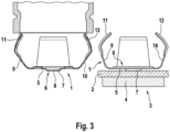
- a friction lining retaining spring 1 is fixed to the back of a back plate 2 of a friction lining 3 of a motor vehicle partial lining disc brake.
- the front of the back plate 2 bears a friction material 4.
- the friction lining retaining spring 1 is cut out in one piece from thin sheet steel material. It comprises a base section 5 that is largely flat and rigid with a central fastening tab 6 comprising a cup and through-opening 8 for the purpose of fixing to the back plate 2. Laterally at the end of the base section 5 there are two U-spring legs 9, 10 that are arranged symmetrically to one another, bent in the shape of a U-yoke and set in a trapezoidal shape.
- Both U-spring legs 9, 10 are angled at an obtuse angle to the base section 5, with each U-spring leg 9, 10 ending with an elbow piece 11, 12 that is bent in the same direction.
- Known knee pieces 11,12 are straight beyond their bending point ( Fig. 1 ).
- a curved or multiply bent elbow piece 11, 12 is proposed, the spring clip 9, 10 of which thus integrates a force reduction.
- a progressively designed lever gear effect can be incorporated so that the force required for insertion assembly is linear.
- the friction lining retaining spring 1 (or alternatively the actuating member, or both components) contains a curved insertion contour, which in the end generates a progressive lever gear effect.
- a particular advantage of an embodiment of the present invention is that a particularly curved insertion contour avoids an exponentially increasing assembly force requirement due to a non-linearly designed lever gear transmission ratio.
- the present invention enables a particularly favorable, optimized engagement between the actuating element and the retaining spring.
- the insertion contour of the elbow piece 11, 12 is degressively curved.
- the curvature of the insertion contour of the elbow piece 11,12 can be designed as a circular arc or otherwise curved, depending on the required gear effect.
- Elliptical or involute curvature is basically possible depending on the desired transmission effect.
- a contact angle between the spring arm and the actuating element is changed positively via its mounting path.
- the force required for axially inserting the friction lining retaining spring 1 into the interior of the actuating element changes continuously over the assembly path.
- the force required is significantly reduced and, for example, reaches a reduction of approximately 35% of the force required for a previously known design (see comparison according to Fig. 1 ).
- the invention also allows the geometry of the insertion contour of the elbow piece 11, 12 to contain multiple bent, i.e. basically straight, sections and/or angles bent in multiple stages, and/or a combination of curvatures with different radii alone and/or in combination with one or more curved and bent sections.
- the geometry defines the reduction effect in the engagement between the actuating element and the insertion contour.
- U-spring leg 9,10 or elbow piece 11,12 can be modified in sections, for example by introducing a work hardening in sections.
- a measure to facilitate assembly which can be used independently or in addition to gear effects and has a direct effect, provides that a corrosion-protected coated retaining spring 1, whose U-spring legs 9, 10 or at least its elbow 11, 12, is provided with a special surface treatment at least on the outside - i.e. in the direction of the brake piston inner wall.
- This can include particularly smooth paired surfaces or a surface coating with tribologically slip-reducing ingredients. Consequently, an integrated or separately applied sliding coating reduces the prevailing contact or sliding friction between the brake piston inner wall and elbow 11, 12. Smoothing, i.e. brushing direction, polishing or grinding direction are aligned with the groove direction parallel to the assembly direction M of the pad retaining spring 1.
- a structural design of the retaining spring 1 or actuating element according to the invention includes an improved gear engagement with an improved engagement angle, whereby the newly improved gear effect has a very favorable effect on a reduction in the insertion force requirement for simplified friction lining assembly. Consequently, the present invention provides a significant reduction in the workload of a worker.
Landscapes
- Engineering & Computer Science (AREA)
- General Engineering & Computer Science (AREA)
- Mechanical Engineering (AREA)
- Braking Arrangements (AREA)
- Springs (AREA)
Description
- Die Erfindung betrifft eine neuartige Reibbelaghaltefeder für einen Kraftfahrzeugscheibenbremsbelag sowie einen neuartigen Kraftfahrzeugscheibenbremsbelag mit Reibbelaghaltefeder.
- Es ist grundsätzlich bekannt, einen Kraftfahrzeugscheibenbremsbelag mit Hilfe elastischer Vorspannung eines sogenannten Federclips anhand einer axial gerichteten Einsteckmontage in eine Innenwandung von einem topfförmigen Betätigungsorgan (wie insbesondere hydraulischer Bremskolben) lösbar einzuklemmen/zu fixieren. Zu diesem Zweck ist an einer Rückenplatte vom Kraftfahrzeugscheibenbremsbelag eine (Reibbelag-)Haltefeder vorgesehen, welche mit einem U-Basisabschnitt mittelbar oder unmittelbar auf der Rückseite der Rückenplatte aufsitzt und unlösbar daran fixiert ist, vgl.
WO 92/18785 A1 WO 94/29611 A1 DE 101 36 235 A1 . Zwecks lösbarer Fixierung am Betätigungsorgan verfügt die Haltefeder über zwei, diametral einander gegenüberliegend arrangierte, elastisch deformierbare, U-Federbügel die nach ordnungsgemäßer Einschub-Montage im Bremskolben mit definierter, nach radial auswärts gerichteter, elastischer Vorspannkraft, in die Innenwandung des topfförmigen Betätigungsorgans/Bremskolben eingeklemmt sind. - Die gattungsgemäßen Reibbelaghaltefedern verfügen an Ihrem U-Federbügel über ein abgekröpftes Kniestück. Ein Nachteil der bekannten Arrangements wird darin gesehen, dass die Einschubmontage der Reibbelaghaltefeder unter ergonomischen Gesichtspunkten verbesserungswürdig angesehen wird. Es ist nachteilig, dass der Kraftbedarf mit fortschreitender Einschubmontage in das Bremskolbeninnere progressiv anwächst. Die angestrebte Verbesserung soll unabhängig von manueller oder robotergestützter Montage sowohl im Fahrzeugbremsenherstellwerk wie auch zur Wartung im Fahrzeugfeld bei reduziertem Aufwand zur Verfügung stehen.
- Es ist daher eine Aufgabe der vorliegenden Erfindung, eine leicht anwendbare Reibbelaghaltefeder, respektive einen verbessert montierbaren Kraftfahrzeugscheibenbremsbelag mit Reibbelaghaltefeder zur Verwendung in einer Kraftfahrzeugteilbelagscheibenbremse vorzulegen.
- In Problemlösung wird erfindungsgemäß vorgeschlagen, dass jedes Kniestück über ein integriertes Getriebemittel verfügt, welches insbesondere als uneben ausgeprägte Bremskolbeneinführbahnkurve derart ausgebildet ist, so dass beim Einführen in den Bremskolben ein definiert vorgegebener Getriebeuntersetzungseffekt zwecks automatischer Beeinflussung bzw. Modellierung des notwendigen Kraftbedarfs vorliegt. Demzufolge wird mit fortschreitender Einschubmontage (Vorschub) der erfindungsgemäßen Reibbelaghaltefeder anhand der Einführbahnkurve eine automatisch angepasste Kraftuntersetzung mit einem Getriebeeffekt nach dem physikalischen Prinzip der Arbeitskraftzerlegung oder Arbeitswegverlängerung derart angeboten, dass der Arbeitskraftbedarf mit der fortschreitenden Einschubmontage zumindest nicht progressiv anwächst. Die beiden genannten physikalischen Maßnahmen (Arbeitskraftzerlegung, Arbeitswegstreckenlängung) können gemeinsam (nebeneinander) an dem Kniestück verkörpert sein. Insbesondere kann die Bahnkurve anhand Wegverlängerung und/oder dadurch automatisch verändert zerlegter Kraftkomponentenanteile (Axialkraftanteil, Radialkraftanteil) einen entsprechend angepassten Getriebeeffekt erzeugen, mit der Folge, dass mit fortschreitendem Montagevorschub ein reduzierter, konstanter oder allenfalls linear anwachsender Einschubkraftbedarf zur elastischen Vorspannung der Bremskolbenhaltefeder ausreicht. Dementsprechend definiert der konkrete Einführbahnkurvenverlauf des Kniestücks den erreichbaren Getriebeeffekt bzw. den Grad der erzielten Krafterleichterung.
- Eine grundsätzlich unabhängig oder zusätzlich zu Getriebeeffekten ausnutzbare Montageerleichterungsmaßnahme sieht vor dass die gesamte Haltefeder, deren U-Federschenkel, beziehungswiese zumindest das Kniestück, zumindest in Richtung zur Bremskolbeninnenwandung mit einer besonderen Oberflächenbehandlung versehen ist. Die Oberflächenbehandlung kann unter anderem eine besondere Beschichtung der Haltefeder beinhalten. Besonders bevorzugt ist es beispielsweise, reibungsreduzierende Bestandteile als Zusatz in eine Korrosionsschutzbeschichtung zu integrieren, welche auf die Metalloberfläche der Bremskolbenhaltefeder aufgebracht ist. Als Alternative ist es möglich, dass eine Gleitbeschichtung als Deckschicht zusätzlich auf eine Korrosionsschutzbeschichtung aufgebracht wird. Insbesondere unbeschichtete Metalloberflächen können vorteilhaft behandelt sein, indem zumindest deren beteiligte Kontaktfläche weitgehend porenfrei, also geglättet (geschliffen, poliert, gebürstet o. ä.) ausgeführt ist. Dabei ist es vorteilhaft, wenn eine Rillenrichtung nach DIN ISO EN 1302 (Schliffbild) weitestgehend parallel zur Montage-Einschubrichtung M der Reibbelaghaltefeder gerichtet ausgeführt ist. Durch die reibungsreduzierte Oberflächenbehandlung wird herrschende Kontakt- bzw. Gleitreibung in Kontaktzonen zwischen Bremskolbeninnenwand und Kniestück herabgesetzt.
- Die vorstehend definierte Erfindung wird schließlich anhand verschiedener Zeichnungen und Ausführungsformen, teilweise im Vergleich zu einer bekannten Haltefederkonstruktion erläutert. In der Zeichnung zeigt:
-
Fig. 1 schematisch Ansicht sowie Montagekraftentwicklung einer konventionellen, bekannten Reibbelaghaltefeder im Einführvorgang in einen Bremskolben, -
Fig. 2 schematisch Ansicht sowie Montagekraftentwicklung einer bevorzugten Ausführungsform einer erfindungsgemäßen Reibbelaghaltefeder, -
Fig. 3 die Ausführungsform nachFig. 2 vergrößert, -
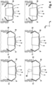
Fig. 4 schematischer Vergleich einer Montagestadienfolge a) erfindungsgemäß (obere Bildreihe) b) konventionell (untere Bildreihe), und -
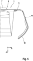
Fig. 5 vergrößerte Teilansicht einer Reibbelaghaltefeder ähnlichFig. 3 . - Eine Reibbelaghaltefeder 1 ist an einer Rückseite einer Rückenplatte 2 eines Reibbelags 3 einer Kraftfahrzeugteilbelagscheibenbremse fixiert. Die Vorderseite der Rückenplatte 2 trägt einen Reibwerkstoff 4. Die Reibbelaghaltefeder 1 ist aus dünnem Stahlblechwerkstoff einstückig ausgetrennt. Sie umfasst einen weitgehend eben sowie biegesteif arrangierten Basisabschnitt 5 mit einer zentralen Befestigungslasche 6 umfassend Napf und Durchgangsöffnung 8 zwecks Fixierung an der Rückenplatte 2. Lateral endseits des Basisabschnitts 5 liegen jeweils zwei symmetrisch zueinander arrangierte, U-Joch förmig gebogene, trapezförmig angestellte, U-Federschenkel 9,10 vor. Beide U-Federschenkel 9,10 sind in stumpfem Winkel zum Basisabschnitt 5 abgewinkelt abgezweigt, wobei jeder U-Federschenkel 9,10 mit einem nochmals gleichsinnig abgekröpften Kniestück 11,12 endet. Bekannte Kniestücke 11,12 sind jenseits Ihrer Abkröpfstelle gradlinig eben (
Fig. 1 ). - Es wird ein insich gekrümmtes, beziehungswiese mehrfach abgekröpftes, Kniestück 11,12 vorgeschlagen, dessen Federbügel 9,10 somit eine Kraftuntersetzung integriert. Insbesondere kann eine progressiv gestaltete Hebelgetriebewirkung inkorporiert sein, so dass der Kraftbedarf zur Einschubmontage linear ist. Mit anderen Worten beinhaltet die Reibbelaghaltefeder 1 (oder alternativ das Betätigungsorgan, beziehungswiese beide Bauteile) eine gekrümmte Einführkontur, welche im Ergebnis einen progressiven Hebelgetriebeeffekt generiert. Ein besonderer Vorteil einer Ausführungsform der vorliegenden Erfindung besteht darin, dass eine besonders gekrümmte Einführkontur durch ein nichtlinear gestaltetes Hebelgetriebeübersetzungsverhältnis einen exponentiell ansteigenden Montagekraftbedarf vermeidet.
- Mit anderen Worten ermöglicht die vorliegende Erfindung einen besonders günstig optimierten Eingriff zwischen Betätigungsorgan und Haltefeder. Insbesondere ist die Einführkontur des Kniestücks 11,12 degressiv gekrümmt.
- Die Krümmung der Einführkontur des Kniestücks 11,12 kann in Abhängigkeit von der benötigen Getriebewirkung als Kreisbogen oder sonstwie gekrümmt gestaltet sein.
- Ellipsen- oder Evolventenkrümmung ist in Abhängigkeit des gewünschten Übersetzungseffekts grundsätzlich möglich. Ein Kontaktwinkel zwischen Federarm und Betätigungsorgan wird positiv über dessen Montageweg verändert.
- Der Kraftbedarf zur axial gerichteten Einschubmontage der Reibbelaghaltefeder 1 in den Innenraum des Betätigungsorgans ändert sich über den Montageweg kontinuierlich. Beim Erreichen der Endmontageposition ist der Kraftbedarf signifikant reduziert und erreicht beispielsweise etwa eine Reduktion um ca. 35% des Kraftbedarfs einer vorbekannten Gestaltung (vgl. Vergleich laut
Fig. 1 ). - Es ist erfindungsgemäß prinzipiell ebenfalls ermöglicht, dass die Geometrie der Einführkontur des Kniestücks 11,12 mehrfach abgekröpfte, also prinzipiell gerade gestaltete Teilabschnitte und/oder mehrstufig gekröpft abgebogene Winkel enthält, und/oder eine Kombination von Krümmungen mit unterschiedlichen Radien alleine und/oder in Kombination mit einem oder mehreren gekrümmten und abgekröpften Teilabschnitt (en) . Durch die Geometrie ist der Untersetzungseffekt im Eingriff zwischen Betätigungsorgan und Einführkontur definiert.
- In Modellierung des Biegewiderstandsmoments des U-Federschenkels bzw. Kniestücks 9,10,11,12 kann dieser insbesondere abschnittsweise verändert sein, indem eine Querschnittsprofilierung, Profilabänderung, Wandstärkenveränderung, Verdickung bzw. Durchgangsöffnung vorgesehen ist. Sämtliche Maßnahmen können einzeln oder in beliebiger Kombination miteinander verknüpft vorliegen, selbst wenn eine solche Bauform nicht durch die Zeichnung dargestellt sein sollte.
- Eine zusätzlich nutzbare Variation besteht darin, dass der Werkstoff des U-Federschenkels 9,10 bzw. Kniestücks 11,12 abschnittsweise modifiziert vorliegen kann, indem beispielsweise eine abschnittsweise Kaltverfestigung eingebracht ist.
- Eine grundsätzlich unabhängig oder zusätzlich zu Getriebeeffekten ausnutzbare Montageerleichterungsmaßnahme, mit unmittelbarer Wirkung, sieht vor dass eine korrosionsgeschützt beschichtete Haltefeder 1, deren U-Federschenkel 9,10 beziehungswiese zumindest dessen Kniestück 11,12, zumindest außenseitig - also in Richtung zur Bremskolbeninnenwandung - mit einer besonderen Oberflächenbehandlung versehen ist. Dies kann besonders glatt gepaarte Oberflächen oder eine Oberflächenbeschichtung mit tribologisch gleitreduzierenden Inhaltsstoffen einschließen. Demzufolge reduziert eine integrierte oder gesondert aufgebrachte Gleitbeschichtung die herrschende Kontakt- bzw. Gleitreibung zwischen Bremskolbeninnenwand und Kniestück 11,12. Glättung also Bürstrichtung, Politur- bzw. Schliffrichtung sind mit Rillenrichtung parallel zur Montagerichtung M der Belaghaltefeder 1 geführt ausgerichtet.
- Kurz gesagt beinhaltet eine erfindungsgemäße konstruktive Gestaltung von Haltefeder 1 bzw. Betätigungsorgan einen verbesserten getrieblichen Eingriff mit verbessertem Eingriffswinkel wobei sich der neuartig verbesserte Getriebeeffekt sehr günstig auf eine Reduktion vom Einschubkraftbedarf zur vereinfachten Reibbelagmontage auswirkt. Demzufolge beinhaltet die vorliegende Erfindung eine deutliche Entlastung eines Werkers.
-
- 1
- Reibbelaghaltefeder
- 2
- Rückenplatte
- 3
- Reibbelag
- 4
- Reibwerkstoff
- 5
- Basisabschnitt
- 6
- Befestigungslasche
- 7
- Napf
- 8
- Durchgangsöffnung
- 9
- Federschenkel
- 10
- Federschenkel
- 11
- Kniestück
- 12
- Kniestück
- M
- Montagerichtung
- Ax
- Axialrichtung
- R
- Radialrichtung
Claims (13)
- Reibbelaghaltefeder (1) für einen Kraftfahrzeugteilbelagscheibenbremsbelag (3), welche aus dünnem Stahlblechwerkstoff einstückig ausgetrennt, als U-Joch gebogen vorliegt, umfassend einen weitgehend eben sowie biegesteif arrangierten U-Basisabschnitt (5), aufweisend eine zentrale Befestigungslasche (6) mit Napf (7) und Durchgangsöffnung (8) zwecks Fixierung an einer Rückenplatte (2) eines Kraftfahrzeugscheibenbremsbelags (3), und mit zwei symmetrisch zueinander arrangierte, jeweils endseits des U-Basisabschnitts (5) trapezförmig in stumpfem Winkel zum Basisabschnitt (5) abgewinkelt abgezweigte U-Federschenkel (9,10), mit Einschubmontage in einen Innenraum eines Betätigungsorgans mit einer Bremskolbeninnenwand, wobei jeder U-Federschenkel (9,10) ein freies Ende aufweist, das als abgekröpftes Kniestück (11,12) ausgebildet ist, wobei jedes Kniestück (11,12) über ein Getriebemittel verfügt, welches als uneben ausgeprägte Bremskolbeneinführbahnkurve derart ausgebildet ist, dass beim Einführen in den Bremskolben ein definiert vorgegebener Getriebeuntersetzungseffekt zwecks automatischer Beeinflussung bzw. Modellierung des notwendigen Kraftbedarfs vorliegt.
- Reibbelaghaltefeder (1) nach Anspruch 1, dadurch gekennzeichnet, dass das Kniestück (11,12) zur Ausbildung der Bremskolbeneinführbahnkurve insich mehrfach abgekröpft abgewinkelt ist.
- Reibbelaghaltefeder (1) nach Anspruch 1 oder 2, dadurch gekennzeichnet, dass das Kniestück (11,12) zur Ausbildung der Bremskolbeneinführbahnkurve über wenigstens einen Bogenabschnitt verfügt.
- Reibbelaghaltefeder (1) nach Anspruch 3, dadurch gekennzeichnet, dass der Bogenabschnitt einen Teil eines Kreisbogens oder einen Teil einer mathematischen Funktion, insbesondere von einer höheren Gattung, wie beispielsweise Evolvente, Elipse, e-Funktion oder ähnlich, beinhaltet.
- Reibbelaghaltefeder (1) nach einem oder mehreren der Ansprüche 1-4, dadurch gekennzeichnet, dass eine segmentierte Bremskolbeneinführbahnkurve vorliegt, welche aus mehreren Abschnitten gleicher Ordnung, oder aus mehreren Abschnitten unterschiedlicher Ordnung, aufgebaut ist.
- Reibbelaghaltefeder (1) nach einem oder mehreren der vorhergehenden Ansprüche 1-5, dadurch gekennzeichnet, dass die Bremskolbeneinführbahnkurve einen progressiven Getriebeeffekt induziert.
- Reibbelaghaltefeder (1) nach einem oder mehreren der vorhergehenden Ansprüche 1-6, dadurch gekennzeichnet, dass jeder U-Federschenkel (9,10) beziehungsweise Kniestück (11,12), zur Modellierung seines Biegewiderstandsmoments, über eine abgeänderte Gestalt verfügt.
- Reibbelaghaltefeder (1) nach einem oder mehreren der vorhergehenden Ansprüche 1-7, dadurch gekennzeichnet, dass jeder U-Federschenkel (9,10) beziehungsweise Kniestück (11,12), zur Modellierung seines Biegewiderstandsmoments, über eine Werkstoffmodifikation verfügt.
- Reibbelaghaltefeder (1) nach einem oder mehreren der vorhergehenden Ansprüche 1-8, dadurch gekennzeichnet, dass zumindest ein Kniestück (11,12) eines U-Federschenkels (9,10) mit einer Oberflächenbehandlung versehen ist.
- Reibbelaghaltefeder (1) nach einem oder mehreren der vorhergehenden Ansprüche 1-9, dadurch gekennzeichnet, dass eine Oberflächenbehandlung eine besondere Beschichtung der Reibbelaghaltefeder (1) beinhalten.
- Reibbelaghaltefeder (1) nach Anspruch 10, dadurch gekennzeichnet, dass eine Korrosionsschutzbeschichtung der Reibbelaghaltefeder (1) reibungsreduzierende Bestandteile integriert, oder dass eine Korrisionsschutzbeschichtung mit einer Gleitbeschichtung als gesonderte Decklage versehen ist.
- Reibbelaghaltefeder (1) nach einem oder mehreren der vorhergehenden Ansprüche 1-11, dadurch gekennzeichnet, dass die Reibbelaghaltefeder (1) in einer Kontaktzone des Kniestücks (11,12) im Wesentlichen geglättet, wie insbesondere gebürstet, geschliffen oder poliert, ausgeführt ist sowie mit zueinander parallel geführter Rillenausrichtung gemäß DIN ISO EN 1302 sowie mit bevorzugt parallel zur Montage-Einschubrichtung M der Reibbelaghaltefeder (1) ausgerichteter Rillenrichtung.
- Kraftfahrzeugteilbelagscheibenbremsbelag (3) mit einer Reibbelaghaltefeder (1) nach einem oder mehreren der Ansprüche 1 - 12.
Priority Applications (1)
| Application Number | Priority Date | Filing Date | Title |
|---|---|---|---|
| PL18746879.8T PL3658796T5 (pl) | 2017-07-28 | 2018-07-24 | Sprężyna mocująca okładzinę cierną dla lepszego mocowania tłoka hamulcowego |
Applications Claiming Priority (3)
| Application Number | Priority Date | Filing Date | Title |
|---|---|---|---|
| DE102017213057 | 2017-07-28 | ||
| DE102017220789.2A DE102017220789B4 (de) | 2017-07-28 | 2017-11-21 | Reibbelaghaltefeder zur verbesserten Bremskolbenfixierung |
| PCT/EP2018/070055 WO2019020636A1 (de) | 2017-07-28 | 2018-07-24 | Reibbelaghaltefeder zur verbesserten bremskolbenfixierung |
Publications (3)
| Publication Number | Publication Date |
|---|---|
| EP3658796A1 EP3658796A1 (de) | 2020-06-03 |
| EP3658796B1 EP3658796B1 (de) | 2021-06-23 |
| EP3658796B2 true EP3658796B2 (de) | 2024-11-27 |
Family
ID=65003939
Family Applications (1)
| Application Number | Title | Priority Date | Filing Date |
|---|---|---|---|
| EP18746879.8A Active EP3658796B2 (de) | 2017-07-28 | 2018-07-24 | Reibbelaghaltefeder zur verbesserten bremskolbenfixierung |
Country Status (11)
| Country | Link |
|---|---|
| US (1) | US11536334B2 (de) |
| EP (1) | EP3658796B2 (de) |
| JP (1) | JP2020525730A (de) |
| KR (1) | KR20200018678A (de) |
| CN (1) | CN110998125A (de) |
| BR (1) | BR112020001092A2 (de) |
| DE (2) | DE102017220789B4 (de) |
| DK (1) | DK3658796T4 (de) |
| ES (1) | ES2881712T5 (de) |
| PL (1) | PL3658796T5 (de) |
| WO (1) | WO2019020636A1 (de) |
Families Citing this family (5)
| Publication number | Priority date | Publication date | Assignee | Title |
|---|---|---|---|---|
| CN111043192A (zh) * | 2019-12-16 | 2020-04-21 | 重庆长安汽车股份有限公司 | 制动钳回位簧、制动卡钳总成及车辆 |
| DE102020106296A1 (de) * | 2020-03-09 | 2021-09-23 | Tmd Friction Services Gmbh | Belagträgerplatte für eine Scheibenbremse eines Kraftfahrzeugs sowie Verfahren zur deren Herstellung |
| DE102020115847B4 (de) | 2020-06-16 | 2021-12-23 | Behr-Hella Thermocontrol Gmbh | Bedieneinheit für ein Fahrzeug |
| IT202200022167A1 (it) | 2022-10-27 | 2024-04-27 | Brembo Spa | Assieme di pastiglia e dispositivo di spinta, pinza freno |
| IT202300004659A1 (it) * | 2023-03-13 | 2024-09-13 | Brembo Spa | Molla di riposizionamento, assieme di pinza freno e molla di riposizionamento |
Citations (9)
| Publication number | Priority date | Publication date | Assignee | Title |
|---|---|---|---|---|
| JPS5693529U (de) † | 1979-12-21 | 1981-07-25 | ||
| JPS5929432U (ja) † | 1982-08-20 | 1984-02-23 | 曙ブレーキ工業株式会社 | 摩擦パツドのガタ止め構造 |
| JPH0425627A (ja) † | 1990-05-18 | 1992-01-29 | Nisshinbo Ind Inc | ディスクブレーキ |
| EP0716246A1 (de) † | 1994-12-07 | 1996-06-12 | ITT Automotive Europe GmbH | Bremsbelagsatz für Schwimmsattel-Scheibenbremse |
| JPH08303499A (ja) † | 1995-05-12 | 1996-11-19 | Hosei Brake Kogyo Kk | ディスクブレーキ |
| EP0989320B1 (de) † | 1998-09-24 | 2006-06-07 | Nissin Kogyo Co., Ltd. | Scheibenbremse für Fahrzeuge |
| JP2007285385A (ja) † | 2006-04-14 | 2007-11-01 | Toyota Motor Corp | ディスクブレーキ装置 |
| DE102013012238A1 (de) † | 2012-07-25 | 2014-01-30 | Doh Hee KIM | Backenfeder für Scheibenbremsen und Herstellungsverfahren dafür |
| WO2016120800A1 (en) † | 2015-01-30 | 2016-08-04 | Freni Brembo S.P.A. | Pad and spring assembly for a disc brake caliper |
Family Cites Families (21)
| Publication number | Priority date | Publication date | Assignee | Title |
|---|---|---|---|---|
| DE7129399U (de) | 1972-04-27 | A Teves Gmbh | Teilbelagscheibenbremse | |
| JPS6058935U (ja) * | 1983-09-29 | 1985-04-24 | アイシン精機株式会社 | インテグラル型デイスクブレ−キ |
| DE3743291A1 (de) | 1987-12-19 | 1989-06-29 | Porsche Ag | Bremsvorrichtung |
| US5494140A (en) * | 1991-04-20 | 1996-02-27 | Alfred Teves Gmbh | Brake shoe with retaining spring |
| DE4112947C2 (de) | 1991-04-20 | 1999-09-16 | Teves Gmbh Alfred | Bremsbacke mit Haltefeder |
| DE4318744C1 (de) | 1993-06-05 | 1994-09-01 | Teves Gmbh Alfred | Schwimmsattel-Scheibenbremse für Kraftfahrzeuge |
| DE4335001C2 (de) | 1993-10-14 | 2001-03-29 | Continental Teves Ag & Co Ohg | Bremsbelag für Scheibenbremsen |
| DE4340453A1 (de) | 1993-11-27 | 1995-06-01 | Teves Gmbh Alfred | Bremskolben für Scheibenbremsen |
| DE19652933A1 (de) * | 1996-12-19 | 1998-06-25 | Teves Gmbh Alfred | Bremsbelag für eine Scheibenbremse |
| DE19855583A1 (de) * | 1997-12-09 | 1999-06-10 | Luk Lamellen & Kupplungsbau | Reibungskupplung |
| DE19858743A1 (de) * | 1998-12-18 | 2000-06-21 | Continental Teves Ag & Co Ohg | Belaghaltefeder für einen Bremsklotz |
| JP2000213571A (ja) | 1999-01-22 | 2000-08-02 | Akebono Brake Ind Co Ltd | ディスクブレ―キ |
| DE10031808A1 (de) | 2000-07-04 | 2002-01-17 | Continental Teves Ag & Co Ohg | Teilbelagscheibenbremse mit einer Haltevorrichtung für einen Bremsbelag |
| DE10136235A1 (de) * | 2000-09-14 | 2002-07-11 | Continental Teves Ag & Co Ohg | Teilbelagsscheibenbremse sowie zugehöriger Bremsbelag mit einer Haltevorrichtung für den Bremsbelag |
| US20090108511A1 (en) * | 2007-10-31 | 2009-04-30 | Bivin Donald B | Variable force spring |
| DE102012023427A1 (de) * | 2012-11-29 | 2014-06-05 | Kostal Kontakt Systeme Gmbh | Steckhülse |
| CN203176229U (zh) | 2013-02-25 | 2013-09-04 | 上海大陆汽车制动系统销售有限公司 | 采用摩擦片三爪弹簧结构的盘式制动器 |
| CN103912608B (zh) | 2013-02-25 | 2016-05-11 | 上海大陆汽车制动系统销售有限公司 | 采用摩擦片三爪弹簧结构的盘式制动器 |
| DE102014006954A1 (de) * | 2014-05-12 | 2015-11-12 | Lucas Automotive Gmbh | Führungseinrichtung für eine Schwimmsattel-Scheibenbremse |
| US9677629B2 (en) * | 2014-08-25 | 2017-06-13 | Akebono Brake Industry Co., Ltd. | Multiple piece pad clip |
| CN205101440U (zh) | 2015-09-25 | 2016-03-23 | 广州汽车集团股份有限公司 | 制动钳总成 |
-
2017
- 2017-11-21 DE DE102017220789.2A patent/DE102017220789B4/de active Active
-
2018
- 2018-07-24 PL PL18746879.8T patent/PL3658796T5/pl unknown
- 2018-07-24 CN CN201880052051.5A patent/CN110998125A/zh active Pending
- 2018-07-24 DK DK18746879.8T patent/DK3658796T4/da active
- 2018-07-24 JP JP2019571618A patent/JP2020525730A/ja active Pending
- 2018-07-24 EP EP18746879.8A patent/EP3658796B2/de active Active
- 2018-07-24 WO PCT/EP2018/070055 patent/WO2019020636A1/de not_active Ceased
- 2018-07-24 ES ES18746879T patent/ES2881712T5/es active Active
- 2018-07-24 DE DE202018006545.5U patent/DE202018006545U1/de active Active
- 2018-07-24 US US16/630,929 patent/US11536334B2/en active Active
- 2018-07-24 KR KR1020207001879A patent/KR20200018678A/ko not_active Ceased
- 2018-07-24 BR BR112020001092-8A patent/BR112020001092A2/pt not_active Application Discontinuation
Patent Citations (9)
| Publication number | Priority date | Publication date | Assignee | Title |
|---|---|---|---|---|
| JPS5693529U (de) † | 1979-12-21 | 1981-07-25 | ||
| JPS5929432U (ja) † | 1982-08-20 | 1984-02-23 | 曙ブレーキ工業株式会社 | 摩擦パツドのガタ止め構造 |
| JPH0425627A (ja) † | 1990-05-18 | 1992-01-29 | Nisshinbo Ind Inc | ディスクブレーキ |
| EP0716246A1 (de) † | 1994-12-07 | 1996-06-12 | ITT Automotive Europe GmbH | Bremsbelagsatz für Schwimmsattel-Scheibenbremse |
| JPH08303499A (ja) † | 1995-05-12 | 1996-11-19 | Hosei Brake Kogyo Kk | ディスクブレーキ |
| EP0989320B1 (de) † | 1998-09-24 | 2006-06-07 | Nissin Kogyo Co., Ltd. | Scheibenbremse für Fahrzeuge |
| JP2007285385A (ja) † | 2006-04-14 | 2007-11-01 | Toyota Motor Corp | ディスクブレーキ装置 |
| DE102013012238A1 (de) † | 2012-07-25 | 2014-01-30 | Doh Hee KIM | Backenfeder für Scheibenbremsen und Herstellungsverfahren dafür |
| WO2016120800A1 (en) † | 2015-01-30 | 2016-08-04 | Freni Brembo S.P.A. | Pad and spring assembly for a disc brake caliper |
Non-Patent Citations (7)
| Title |
|---|
| 1 January 2007, SPRINGER, ISBN: 978-3-540-49868-1, article MEISSNER MANFRED: "Metallfedern, Grundlagen, Werkstoffe, Berechnung, Gestaltung und Rechnereinsatz", pages: 1 - 166 † |
| 1 October 2005, VIEWEG & SOHN VERLAG, ISBN: 978-3-8348-0078-7, article BÜRGEL RALF: "Festigkeitslehre und Werkstoffmechanik. Band 2", pages: 1 - 109 † |
| Maschinenübersetzung von JP H0425627 A † |
| Maschinenübersetzung von JP S5693529 U † |
| Onlineshop Beuth-Verlag- DIN EN ISO 1302 Berichtigung 1- 2008-08 (abgerufen am 08.02.2022) † |
| Onlineshop Beuth-Verlag: DIN EN ISO 1302: 2002-06 (abgerufen am 08.02.2022) † |
| Onlineshop Beuth-Verlag: DIN EN ISO 1302:1993-12 (abgerufen am 08.02.2022) † |
Also Published As
| Publication number | Publication date |
|---|---|
| CN110998125A (zh) | 2020-04-10 |
| JP2020525730A (ja) | 2020-08-27 |
| ES2881712T3 (es) | 2021-11-30 |
| EP3658796A1 (de) | 2020-06-03 |
| BR112020001092A2 (pt) | 2020-07-21 |
| PL3658796T5 (pl) | 2025-07-07 |
| ES2881712T5 (en) | 2025-04-14 |
| DE202018006545U1 (de) | 2021-01-25 |
| DK3658796T4 (da) | 2025-02-17 |
| US20200232528A1 (en) | 2020-07-23 |
| WO2019020636A1 (de) | 2019-01-31 |
| DE102017220789B4 (de) | 2023-08-10 |
| DE102017220789A1 (de) | 2019-01-31 |
| DK3658796T3 (da) | 2021-09-13 |
| US11536334B2 (en) | 2022-12-27 |
| KR20200018678A (ko) | 2020-02-19 |
| PL3658796T3 (pl) | 2022-01-10 |
| EP3658796B1 (de) | 2021-06-23 |
Similar Documents
| Publication | Publication Date | Title |
|---|---|---|
| EP3658796B2 (de) | Reibbelaghaltefeder zur verbesserten bremskolbenfixierung | |
| EP3417187B1 (de) | Reibbelaganordnung mit rückstellfeder zur lüftspiellimitierung für eine kraftfahrzeugteilbelagscheibenbremse | |
| EP3956582B1 (de) | Kraftfahrzeugscheibenbremsbelag mit reibbelagrückstellfeder | |
| WO2007088202A1 (de) | Befestigungselement für fahrzeugteile | |
| DE10233446A1 (de) | Bremshalter einer Schwimmsattel-Scheibenbremse mit Bremsbelagführungsfeder | |
| DE102008019263B4 (de) | Bremsscheiben/Nabenverbindung | |
| DE202012102395U1 (de) | Sprengring | |
| WO2008022781A1 (de) | Ausgleichsgewicht für den unwuchtausgleich eines fahrzeugrades | |
| EP1999395A2 (de) | Belagträger für bremseinrichtungen, insbesondere trommelbremsen, träger-reibbelag-einheit und belagträgerhalter einer pressvorrichtung | |
| DE102012003104B4 (de) | Im Bremssattel einer Scheibenbremse angeordnete Zuspanneinrichtung | |
| EP3596354B1 (de) | Bremsträger und scheibenbremse | |
| EP4139583A1 (de) | Kraftfahrscheibenbremsreibbelag mit im klemmsitz auf einem sattelvorsprung rittlings fixierbarer drahtschraubenfeder | |
| DE1750769A1 (de) | Teilbelagscheibenbremse | |
| EP2815145A1 (de) | Trommelbremsbacke | |
| DE102012017979B4 (de) | Spindelantrieb | |
| EP1916437B1 (de) | Bremsbelag für eine Scheibenbremse | |
| DE102012203167A1 (de) | Dichtungsanordnung | |
| DE102015104915B4 (de) | Anordnung einer Stellspindel in einer Brücke einer pneumatisch oder elektromotorisch betätigbaren Scheibenbremse und Scheibenbremse | |
| DE102013208001A1 (de) | Scheibenbremse mit einer Blende | |
| DE102006052178A1 (de) | Bremsbelag für eine Teilbelag-Scheibenbremse | |
| DE202020005763U1 (de) | Hammerkopfförmiger Kraftfahrscheibenbremsreibbelag mit durch Klemmsitz auf einem Federsattelvorsprung rittlings fixierter Stahldrahtschraubenfeder | |
| DE102014019110B4 (de) | Befestigung eines Bremssattels einer Scheibenbremse an einem Bremsträger | |
| AT502907B1 (de) | Auswuchtgewicht für drehende körper, insbesondere fahrzeugräder | |
| WO2017121715A2 (de) | Kraftfahrzeugscheibenbremsbelag mit rückenplattenseitiger erhebung sowie dämpfungsplatte zur applikation an einem entsprechenden kraftfahrzeugscheibenbremsbelag einschliesslich deren verwendung in einer kraftfahrzeugscheibenbremse | |
| DE202015005486U1 (de) | Kennzeichenhalterung |
Legal Events
| Date | Code | Title | Description |
|---|---|---|---|
| REG | Reference to a national code |
Ref country code: DE Ref legal event code: R138 Ref document number: 202018006545 Country of ref document: DE Free format text: GERMAN DOCUMENT NUMBER IS 502018005846 |
|
| STAA | Information on the status of an ep patent application or granted ep patent |
Free format text: STATUS: UNKNOWN |
|
| STAA | Information on the status of an ep patent application or granted ep patent |
Free format text: STATUS: THE INTERNATIONAL PUBLICATION HAS BEEN MADE |
|
| PUAI | Public reference made under article 153(3) epc to a published international application that has entered the european phase |
Free format text: ORIGINAL CODE: 0009012 |
|
| STAA | Information on the status of an ep patent application or granted ep patent |
Free format text: STATUS: REQUEST FOR EXAMINATION WAS MADE |
|
| 17P | Request for examination filed |
Effective date: 20200228 |
|
| AK | Designated contracting states |
Kind code of ref document: A1 Designated state(s): AL AT BE BG CH CY CZ DE DK EE ES FI FR GB GR HR HU IE IS IT LI LT LU LV MC MK MT NL NO PL PT RO RS SE SI SK SM TR |
|
| AX | Request for extension of the european patent |
Extension state: BA ME |
|
| RAP1 | Party data changed (applicant data changed or rights of an application transferred) |
Owner name: CONTINENTAL TEVES AG & CO. OHG |
|
| DAV | Request for validation of the european patent (deleted) | ||
| DAX | Request for extension of the european patent (deleted) | ||
| GRAP | Despatch of communication of intention to grant a patent |
Free format text: ORIGINAL CODE: EPIDOSNIGR1 |
|
| STAA | Information on the status of an ep patent application or granted ep patent |
Free format text: STATUS: GRANT OF PATENT IS INTENDED |
|
| INTG | Intention to grant announced |
Effective date: 20210122 |
|
| GRAS | Grant fee paid |
Free format text: ORIGINAL CODE: EPIDOSNIGR3 |
|
| GRAA | (expected) grant |
Free format text: ORIGINAL CODE: 0009210 |
|
| STAA | Information on the status of an ep patent application or granted ep patent |
Free format text: STATUS: THE PATENT HAS BEEN GRANTED |
|
| AK | Designated contracting states |
Kind code of ref document: B1 Designated state(s): AL AT BE BG CH CY CZ DE DK EE ES FI FR GB GR HR HU IE IS IT LI LT LU LV MC MK MT NL NO PL PT RO RS SE SI SK SM TR |
|
| REG | Reference to a national code |
Ref country code: GB Ref legal event code: FG4D Free format text: NOT ENGLISH |
|
| REG | Reference to a national code |
Ref country code: CH Ref legal event code: EP |
|
| REG | Reference to a national code |
Ref country code: DE Ref legal event code: R096 Ref document number: 502018005846 Country of ref document: DE Ref country code: AT Ref legal event code: REF Ref document number: 1404564 Country of ref document: AT Kind code of ref document: T Effective date: 20210715 |
|
| REG | Reference to a national code |
Ref country code: IE Ref legal event code: FG4D Free format text: LANGUAGE OF EP DOCUMENT: GERMAN |
|
| REG | Reference to a national code |
Ref country code: RO Ref legal event code: EPE |
|
| REG | Reference to a national code |
Ref country code: DK Ref legal event code: T3 Effective date: 20210908 |
|
| REG | Reference to a national code |
Ref country code: SK Ref legal event code: T3 Ref document number: E 37792 Country of ref document: SK |
|
| REG | Reference to a national code |
Ref country code: LT Ref legal event code: MG9D |
|
| PG25 | Lapsed in a contracting state [announced via postgrant information from national office to epo] |
Ref country code: FI Free format text: LAPSE BECAUSE OF FAILURE TO SUBMIT A TRANSLATION OF THE DESCRIPTION OR TO PAY THE FEE WITHIN THE PRESCRIBED TIME-LIMIT Effective date: 20210623 Ref country code: HR Free format text: LAPSE BECAUSE OF FAILURE TO SUBMIT A TRANSLATION OF THE DESCRIPTION OR TO PAY THE FEE WITHIN THE PRESCRIBED TIME-LIMIT Effective date: 20210623 Ref country code: LT Free format text: LAPSE BECAUSE OF FAILURE TO SUBMIT A TRANSLATION OF THE DESCRIPTION OR TO PAY THE FEE WITHIN THE PRESCRIBED TIME-LIMIT Effective date: 20210623 Ref country code: BG Free format text: LAPSE BECAUSE OF FAILURE TO SUBMIT A TRANSLATION OF THE DESCRIPTION OR TO PAY THE FEE WITHIN THE PRESCRIBED TIME-LIMIT Effective date: 20210923 |
|
| PG25 | Lapsed in a contracting state [announced via postgrant information from national office to epo] |
Ref country code: LV Free format text: LAPSE BECAUSE OF FAILURE TO SUBMIT A TRANSLATION OF THE DESCRIPTION OR TO PAY THE FEE WITHIN THE PRESCRIBED TIME-LIMIT Effective date: 20210623 Ref country code: NO Free format text: LAPSE BECAUSE OF FAILURE TO SUBMIT A TRANSLATION OF THE DESCRIPTION OR TO PAY THE FEE WITHIN THE PRESCRIBED TIME-LIMIT Effective date: 20210923 Ref country code: SE Free format text: LAPSE BECAUSE OF FAILURE TO SUBMIT A TRANSLATION OF THE DESCRIPTION OR TO PAY THE FEE WITHIN THE PRESCRIBED TIME-LIMIT Effective date: 20210623 Ref country code: RS Free format text: LAPSE BECAUSE OF FAILURE TO SUBMIT A TRANSLATION OF THE DESCRIPTION OR TO PAY THE FEE WITHIN THE PRESCRIBED TIME-LIMIT Effective date: 20210623 Ref country code: GR Free format text: LAPSE BECAUSE OF FAILURE TO SUBMIT A TRANSLATION OF THE DESCRIPTION OR TO PAY THE FEE WITHIN THE PRESCRIBED TIME-LIMIT Effective date: 20210924 |
|
| REG | Reference to a national code |
Ref country code: ES Ref legal event code: FG2A Ref document number: 2881712 Country of ref document: ES Kind code of ref document: T3 Effective date: 20211130 |
|
| REG | Reference to a national code |
Ref country code: NL Ref legal event code: MP Effective date: 20210623 |
|
| PG25 | Lapsed in a contracting state [announced via postgrant information from national office to epo] |
Ref country code: CZ Free format text: LAPSE BECAUSE OF FAILURE TO SUBMIT A TRANSLATION OF THE DESCRIPTION OR TO PAY THE FEE WITHIN THE PRESCRIBED TIME-LIMIT Effective date: 20210623 Ref country code: SM Free format text: LAPSE BECAUSE OF FAILURE TO SUBMIT A TRANSLATION OF THE DESCRIPTION OR TO PAY THE FEE WITHIN THE PRESCRIBED TIME-LIMIT Effective date: 20210623 Ref country code: PT Free format text: LAPSE BECAUSE OF FAILURE TO SUBMIT A TRANSLATION OF THE DESCRIPTION OR TO PAY THE FEE WITHIN THE PRESCRIBED TIME-LIMIT Effective date: 20211025 Ref country code: NL Free format text: LAPSE BECAUSE OF FAILURE TO SUBMIT A TRANSLATION OF THE DESCRIPTION OR TO PAY THE FEE WITHIN THE PRESCRIBED TIME-LIMIT Effective date: 20210623 Ref country code: EE Free format text: LAPSE BECAUSE OF FAILURE TO SUBMIT A TRANSLATION OF THE DESCRIPTION OR TO PAY THE FEE WITHIN THE PRESCRIBED TIME-LIMIT Effective date: 20210623 |
|
| REG | Reference to a national code |
Ref country code: DE Ref legal event code: R026 Ref document number: 502018005846 Country of ref document: DE |
|
| PLBI | Opposition filed |
Free format text: ORIGINAL CODE: 0009260 |
|
| REG | Reference to a national code |
Ref country code: CH Ref legal event code: PL |
|
| 26 | Opposition filed |
Opponent name: ZF FRIEDRICHSHAFEN AG Effective date: 20220223 |
|
| PG25 | Lapsed in a contracting state [announced via postgrant information from national office to epo] |
Ref country code: MC Free format text: LAPSE BECAUSE OF FAILURE TO SUBMIT A TRANSLATION OF THE DESCRIPTION OR TO PAY THE FEE WITHIN THE PRESCRIBED TIME-LIMIT Effective date: 20210623 |
|
| REG | Reference to a national code |
Ref country code: BE Ref legal event code: MM Effective date: 20210731 |
|
| PLAX | Notice of opposition and request to file observation + time limit sent |
Free format text: ORIGINAL CODE: EPIDOSNOBS2 |
|
| PG25 | Lapsed in a contracting state [announced via postgrant information from national office to epo] |
Ref country code: LI Free format text: LAPSE BECAUSE OF NON-PAYMENT OF DUE FEES Effective date: 20210731 Ref country code: CH Free format text: LAPSE BECAUSE OF NON-PAYMENT OF DUE FEES Effective date: 20210731 |
|
| PG25 | Lapsed in a contracting state [announced via postgrant information from national office to epo] |
Ref country code: LU Free format text: LAPSE BECAUSE OF NON-PAYMENT OF DUE FEES Effective date: 20210724 Ref country code: AL Free format text: LAPSE BECAUSE OF FAILURE TO SUBMIT A TRANSLATION OF THE DESCRIPTION OR TO PAY THE FEE WITHIN THE PRESCRIBED TIME-LIMIT Effective date: 20210623 |
|
| RAP2 | Party data changed (patent owner data changed or rights of a patent transferred) |
Owner name: CONTINENTAL AUTOMOTIVE TECHNOLOGIES GMBH |
|
| PG25 | Lapsed in a contracting state [announced via postgrant information from national office to epo] |
Ref country code: IE Free format text: LAPSE BECAUSE OF NON-PAYMENT OF DUE FEES Effective date: 20210724 Ref country code: BE Free format text: LAPSE BECAUSE OF NON-PAYMENT OF DUE FEES Effective date: 20210731 |
|
| PLBB | Reply of patent proprietor to notice(s) of opposition received |
Free format text: ORIGINAL CODE: EPIDOSNOBS3 |
|
| REG | Reference to a national code |
Ref country code: DE Ref legal event code: R081 Ref document number: 502018005846 Country of ref document: DE Owner name: CONTINENTAL AUTOMOTIVE TECHNOLOGIES GMBH, DE Free format text: FORMER OWNER: CONTINENTAL TEVES AG & CO. OHG, 60488 FRANKFURT, DE Ref country code: DE Ref legal event code: R081 Ref document number: 502018005846 Country of ref document: DE Owner name: AUMOVIO GERMANY GMBH, DE Free format text: FORMER OWNER: CONTINENTAL TEVES AG & CO. OHG, 60488 FRANKFURT, DE |
|
| REG | Reference to a national code |
Ref country code: GB Ref legal event code: 732E Free format text: REGISTERED BETWEEN 20230216 AND 20230222 |
|
| REG | Reference to a national code |
Ref country code: SK Ref legal event code: PC4A Ref document number: E 37792 Country of ref document: SK Owner name: CONTINENTAL AUTOMOTIVE TECHNOLOGIES GMBH, HANN, DE Free format text: FORMER OWNER: CONTINENTAL TEVES AG & CO. OHG, FRANKFURT AM MAIN, DE Effective date: 20230227 |
|
| P01 | Opt-out of the competence of the unified patent court (upc) registered |
Effective date: 20230522 |
|
| PG25 | Lapsed in a contracting state [announced via postgrant information from national office to epo] |
Ref country code: CY Free format text: LAPSE BECAUSE OF FAILURE TO SUBMIT A TRANSLATION OF THE DESCRIPTION OR TO PAY THE FEE WITHIN THE PRESCRIBED TIME-LIMIT Effective date: 20210623 |
|
| PG25 | Lapsed in a contracting state [announced via postgrant information from national office to epo] |
Ref country code: HU Free format text: LAPSE BECAUSE OF FAILURE TO SUBMIT A TRANSLATION OF THE DESCRIPTION OR TO PAY THE FEE WITHIN THE PRESCRIBED TIME-LIMIT; INVALID AB INITIO Effective date: 20180724 |
|
| PLAB | Opposition data, opponent's data or that of the opponent's representative modified |
Free format text: ORIGINAL CODE: 0009299OPPO |
|
| R26 | Opposition filed (corrected) |
Opponent name: ZF FRIEDRICHSHAFEN AG Effective date: 20220223 |
|
| REG | Reference to a national code |
Ref country code: DE Ref legal event code: R081 Ref document number: 502018005846 Country of ref document: DE Owner name: CONTINENTAL AUTOMOTIVE TECHNOLOGIES GMBH, DE Free format text: FORMER OWNER: CONTINENTAL AUTOMOTIVE TECHNOLOGIES GMBH, 30165 HANNOVER, DE Ref country code: DE Ref legal event code: R081 Ref document number: 502018005846 Country of ref document: DE Owner name: AUMOVIO GERMANY GMBH, DE Free format text: FORMER OWNER: CONTINENTAL AUTOMOTIVE TECHNOLOGIES GMBH, 30165 HANNOVER, DE |
|
| RAP4 | Party data changed (patent owner data changed or rights of a patent transferred) |
Owner name: CONTINENTAL AUTOMOTIVE TECHNOLOGIES GMBH |
|
| PG25 | Lapsed in a contracting state [announced via postgrant information from national office to epo] |
Ref country code: MK Free format text: LAPSE BECAUSE OF FAILURE TO SUBMIT A TRANSLATION OF THE DESCRIPTION OR TO PAY THE FEE WITHIN THE PRESCRIBED TIME-LIMIT Effective date: 20210623 |
|
| REG | Reference to a national code |
Ref country code: CH Ref legal event code: PK Free format text: DIE PUBLIKATION VOM 27.03.2024 WURDE AM 24.04.2024 IRRTUEMLICHERWEISE ERNEUT PUBLIZIERT. LA PUBLICATION DU 27.03.2024 A ETE REPUBLIEE PAR ERREUR LE 24.04.2024. LA PUBBLICAZIONE DEL 27.03.2024 E STATA ERRONEAMENTE RIPUBBLICATA IL 24.04.2024. |
|
| REG | Reference to a national code |
Ref country code: AT Ref legal event code: MM01 Ref document number: 1404564 Country of ref document: AT Kind code of ref document: T Effective date: 20230724 |
|
| PG25 | Lapsed in a contracting state [announced via postgrant information from national office to epo] |
Ref country code: MT Free format text: LAPSE BECAUSE OF FAILURE TO SUBMIT A TRANSLATION OF THE DESCRIPTION OR TO PAY THE FEE WITHIN THE PRESCRIBED TIME-LIMIT Effective date: 20210623 |
|
| PG25 | Lapsed in a contracting state [announced via postgrant information from national office to epo] |
Ref country code: AT Free format text: LAPSE BECAUSE OF NON-PAYMENT OF DUE FEES Effective date: 20230724 |
|
| PUAH | Patent maintained in amended form |
Free format text: ORIGINAL CODE: 0009272 |
|
| STAA | Information on the status of an ep patent application or granted ep patent |
Free format text: STATUS: PATENT MAINTAINED AS AMENDED |
|
| PG25 | Lapsed in a contracting state [announced via postgrant information from national office to epo] |
Ref country code: AT Free format text: LAPSE BECAUSE OF NON-PAYMENT OF DUE FEES Effective date: 20230724 |
|
| 27A | Patent maintained in amended form |
Effective date: 20241127 |
|
| AK | Designated contracting states |
Kind code of ref document: B2 Designated state(s): AL AT BE BG CH CY CZ DE DK EE ES FI FR GB GR HR HU IE IS IT LI LT LU LV MC MK MT NL NO PL PT RO RS SE SI SK SM TR |
|
| REG | Reference to a national code |
Ref country code: DE Ref legal event code: R102 Ref document number: 502018005846 Country of ref document: DE |
|
| REG | Reference to a national code |
Ref country code: DK Ref legal event code: T4 Effective date: 20250213 |
|
| REG | Reference to a national code |
Ref country code: SK Ref legal event code: TC4A Ref document number: E 37792 Country of ref document: SK Owner name: CONTINENTAL AUTOMOTIVE TECHNOLOGIES GMBH, HANN, DE Effective date: 20250221 Ref country code: SK Ref legal event code: T5 Ref document number: E 37792 Country of ref document: SK |
|
| REG | Reference to a national code |
Ref country code: ES Ref legal event code: DC2A Ref document number: 2881712 Country of ref document: ES Kind code of ref document: T5 Effective date: 20250414 |
|
| PGFP | Annual fee paid to national office [announced via postgrant information from national office to epo] |
Ref country code: ES Payment date: 20250827 Year of fee payment: 8 |
|
| PGFP | Annual fee paid to national office [announced via postgrant information from national office to epo] |
Ref country code: DK Payment date: 20250725 Year of fee payment: 8 Ref country code: DE Payment date: 20250731 Year of fee payment: 8 |
|
| PGFP | Annual fee paid to national office [announced via postgrant information from national office to epo] |
Ref country code: PL Payment date: 20250721 Year of fee payment: 8 Ref country code: TR Payment date: 20250716 Year of fee payment: 8 Ref country code: IT Payment date: 20250724 Year of fee payment: 8 |
|
| PGFP | Annual fee paid to national office [announced via postgrant information from national office to epo] |
Ref country code: GB Payment date: 20250722 Year of fee payment: 8 |
|
| PGFP | Annual fee paid to national office [announced via postgrant information from national office to epo] |
Ref country code: FR Payment date: 20250725 Year of fee payment: 8 |
|
| PGFP | Annual fee paid to national office [announced via postgrant information from national office to epo] |
Ref country code: RO Payment date: 20250716 Year of fee payment: 8 |
|
| PGFP | Annual fee paid to national office [announced via postgrant information from national office to epo] |
Ref country code: SK Payment date: 20250716 Year of fee payment: 8 |
|
| REG | Reference to a national code |
Ref country code: DE Ref legal event code: R081 Ref document number: 502018005846 Country of ref document: DE Owner name: AUMOVIO GERMANY GMBH, DE Free format text: FORMER OWNER: CONTINENTAL AUTOMOTIVE TECHNOLOGIES GMBH, 30175 HANNOVER, DE |
|
| PGFP | Annual fee paid to national office [announced via postgrant information from national office to epo] |
Ref country code: AT Payment date: 20260410 Year of fee payment: 5 |