EP3656258B1 - Paketbox - Google Patents
Paketbox Download PDFInfo
- Publication number
- EP3656258B1 EP3656258B1 EP19205833.7A EP19205833A EP3656258B1 EP 3656258 B1 EP3656258 B1 EP 3656258B1 EP 19205833 A EP19205833 A EP 19205833A EP 3656258 B1 EP3656258 B1 EP 3656258B1
- Authority
- EP
- European Patent Office
- Prior art keywords
- receiving device
- parcel box
- parcel
- box according
- designed
- Prior art date
- Legal status (The legal status is an assumption and is not a legal conclusion. Google has not performed a legal analysis and makes no representation as to the accuracy of the status listed.)
- Active
Links
Images




Classifications
-
- A—HUMAN NECESSITIES
- A47—FURNITURE; DOMESTIC ARTICLES OR APPLIANCES; COFFEE MILLS; SPICE MILLS; SUCTION CLEANERS IN GENERAL
- A47G—HOUSEHOLD OR TABLE EQUIPMENT
- A47G29/00—Supports, holders, or containers for household use, not provided for in groups A47G1/00-A47G27/00 or A47G33/00
- A47G29/14—Deposit receptacles for food, e.g. breakfast, milk, or large parcels; Similar receptacles for food or large parcels with appliances for preventing unauthorised removal of the deposited articles, i.e. food or large parcels
- A47G29/20—Deposit receptacles for food, e.g. breakfast, milk, or large parcels; Similar receptacles for food or large parcels with appliances for preventing unauthorised removal of the deposited articles, i.e. food or large parcels with appliances for preventing unauthorised removal of the deposited articles
- A47G29/22—Deposit receptacles for food, e.g. breakfast, milk, or large parcels; Similar receptacles for food or large parcels with appliances for preventing unauthorised removal of the deposited articles, i.e. food or large parcels with appliances for preventing unauthorised removal of the deposited articles having rotatable or reciprocable parts
Definitions
- the invention relates to a parcel box that is suitable, among other things, for the delivery, collection, storage or acceptance of shipping parcels.
- Parcel boxes are particularly suitable as an additional acceptance device for parcels in addition to the usual mailbox in the household or commercial environment.
- WO 2006/015307 A2 discloses a package collection device that is intended to enable barrier-free operation for disabled people.
- the pick-up device can be actuated with little force and a maximum actuation height using a lever mechanism, springs and weights.
- DE 10 2006 039 002 A1 discloses a collection container for collecting parcels with a deposit opening, an acceptance device and a storage space.
- the previously known parcel acceptance devices are not optimally suited for direct loading by a parcel deliverer while at the same time being used in the open air in a weather-resistant manner.
- EP 1 252 845 A1 discloses an acceptance device for data carriers with electronic chips.
- the device includes a scanner for contactless electronic recognition of specific objects, regardless of their position in the acceptance device.
- the device is powered by a stepper motor and will only accept items if a valid signal from a chip on the item is detected.
- a common problem when dropping a package into a package delivery box is that the operator must first open the device or activate a mechanism before the package can be inserted into an appropriate device.
- the object of the present invention is to provide an improved parcel box.
- the invention solves the problem with the features of the main claim.
- the disclosed parcel box is suitable for delivering one or more parcels to an addressee. Parcels can also be collected for shipping. The parcels are stored safely in the parcel box and are protected from the weather.
- the parcel box disclosed comprises a receiving device and a collection container.
- the receiving device is pivotable. One or more packages can be placed in the receiving device. In the basic position, the receiving device is already accessible from the outside for loading.
- the package is placed on a storage area of the receiving device.
- An approaching person can simply place a package in the receiving device without operating a mechanism.
- the basic position of the receiving device is also the loading position.
- the basic position describes the equilibrium position of the recording device. Without external influence, the recording device remains in the basic position, so that loading is easily possible at any time. In the basic position, the recording device should remain in particular before and after actuation.
- the parcel box has restoring means, by means of which the receiving device pivots back into the basic position on its own.
- the receiving device After loading the receiving device, the receiving device can be pivoted into a tilted position.
- the rotation of the receiving device allows the parcel to slide inside the parcel box into the collection container.
- the pivoting movement can be a rotation about a predetermined axis.
- a more complex pivoting movement can be implemented using multi-body kinematics.
- a picked-up package preferably slips out of the pick-up device into the collection container due to its own weight.
- the parcels picked up are safely stored in the collection container.
- the packages can be removed at a later point in time by means of a removal access.
- the parcel box advantageously includes a lockable door.
- the parcel box is advantageously also secured against unauthorized access to the parcels.
- the receiving device is preferably used by the operator between the loading position and the tilting position panned.
- the receiving device has a corresponding handle on the front side.
- the recording device can be operated with one hand. This is particularly advantageous for the delivery of several parcels in a row.
- a particular advantage of the disclosed parcel box results from the basic position of the receiving device.
- the parcel box is designed to be loaded without prior operation.
- the receiving device is preferably open at the front.
- the receiving device preferably forms a feed chute that is open towards the front.
- a deliverer can insert a parcel directly into the parcel box in its basic position.
- the parcel box can be placed inside a living area or outside of a living area.
- the parcel box is particularly suitable for outdoor use. Due to its design, no rainwater collects in the receiving device. Incoming water can flow off to the front.
- FIG 1 shows an embodiment of a parcel box (100).
- the parcel box (100) comprises a receiving device (200) and a collection container (300).
- the receiving device (200) is designed to receive a package (P).
- the receiving device (200) comprises a storage area (205).
- the receiving device (200) forms a feed shaft (210).
- the feed shaft (210) is formed by one or more walls (201).
- the feed chute (210) is preferably cuboid. One or more side faces of the cuboid shape can be open.
- the dimensions of the receiving device (200) are preferably based on the usual standard package sizes.
- the dimensions of the feed chute preferably offer a few centimeters of play compared to a maximum standard package size. This design enables a compact and space-saving design.
- An embodiment of the receiving device with a side wall and/or a top wall is particularly advantageous.
- the walls (201) form a well-defined shaft. Canting of the package is prevented.
- the parcel box (100) also includes an integrated collection container (300).
- the collection container (300) is designed to keep the stored packages safe.
- the dimensions of the collection container (300) depend on the desired application.
- the collection container (300) is dimensioned in such a way that there is space for several packages and parcels.
- the parcel box (100) preferably has dimensions of 0.5 m to 1.5 m in width and/or depth.
- the parcel box is preferably 1m to 2.5m high.
- the receiving device (200) is preferably designed for specific package sizes.
- Preferred package sizes are 0.35m x 0.25m x 0.1m packages, 0.6m x 0.3m x 1.5m packages, 0.6m x 0.3m x 0.15m packages, 1.2m packages ⁇ 0.6m ⁇ 0.6m and/or packages up to 1.2m ⁇ 0.6m ⁇ 0.6m.
- the parcel box (100), in particular the collection container (300), is preferably dimensioned sufficiently deep so that several parcels can be stored one behind the other in the depth of the parcel box.
- the parcel box (100) preferably includes a removal access (310).
- the removal access (310) is preferably designed as a door.
- the door can be lockable.
- a lockable door is particularly advantageous for access control to the stored packages.
- the parcel box (100) includes rollers (400).
- the parcel box (100) is mobile in this embodiment.
- the parcel box (100) can be placed anywhere inside or outside of a building.
- the parcel box (100) can have feet.
- the rollers can be designed so that they can be braked.
- the parcel box (100) is also preferably designed to be weatherproof.
- the parcel box (100) advantageously has a roof (500).
- the roof (500) preferably has a gradient. This allows rainwater to drain away.
- the roof (500) preferably protrudes in at least one direction over the body of the parcel box.
- the projection of the roof over the base of the parcel box is advantageous in order to offer additional protection against rain and the effects of the weather.
- the parcel box (100) is protected from rain by a shield, particularly on the front, i.e. the side from which the receiving device (200) can be loaded.
- the receiving device (200) advantageously comprises a handle (220).
- the receiving device (200) can be pivoted on the handle (220).
- the receiving device can have a mechanical and/or electrical drive.
- the pivoting movement of the receiving device (200) can be supported by a spring and/or a drive.
- the parcel box (100) advantageously includes restoring means for restoring the receiving device to the basic position, i.e. the loading position (S1).
- restoring means act preferably in the direction of the basic position.
- Means for supporting the tilting movement can also act in certain areas along the pivoting movement. It's special advantageous to let the restoring means and/or the tilting support means act with different intensity in certain areas of the pivoting movement. This can be realized in particular by using suitable lever kinematics.
- the pivoting movement can in particular be supported in a controllable manner.
- the parcel box (100) includes a lock (250) for the receiving device (200).
- the receiving device (200) can be locked with a lock (250).
- packages can no longer be tipped into the collection container (300). This is particularly advantageous if the addressee is absent for a longer period of time.
- the lock (250) advantageously comprises a lock.
- the lock (250) can preferably be blocked with a key.
- FIG 2 shows a semi-transparent side view of an advantageous parcel box.
- the parcel box (100) is preferably designed as a frame construction.
- the walls can consist in particular of sheet metal.
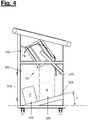
- FIGs 2 to 4 show the internal structure of the parcel box with the receiving device in different positions.
- figure 2 shows a loading position (S1).
- figure 3 shows a transitional position (S2).
- figure 4 shows the recording device in a tilted position (S3).
- the receiving device In the loading position (S1), the receiving device is ready to be loaded with a package.
- the loading position (S1) also forms the basic position of the receiving device.
- the receiving device (200) is preferably designed so that liquids or solid debris can flow or slide out of the receiving device (200).
- the receiving device (200) is preferably designed without undercuts.
- the shelf (205) is particularly open at the front edge. That is, no upwardly protruding projection is arranged on the front edge. This makes it particularly easy to wipe the storage surface. Leaves or other debris cannot accumulate in undercuts.
- the cross section of the feed chute (210) only increases towards the front or remains constant. In particular, the receiving device (200) does not narrow the cross section at the front.
- the storage surface (205) preferably has a slight incline towards the front.
- the loading position (S1) of the receiving device (200) is preferably designed in such a way that the receiving device is inclined to the horizontal.
- the shelf (205) is preferably inclined at a run-off angle (X) to a horizontal (H).
- the inclination preferably forms a gradient towards the front of the parcel box.
- the run-off angle (X) is approximately 5 degrees.
- the drainage angle In a further embodiment, (X) can also be 5-25 degrees, preferably 20 degrees.
- the slope is designed in such a way that liquids can flow out of the receiving device to the outside. This prevents liquids from entering the interior of the parcel box.
- the receiving device can be sealed, in particular on the back.
- a handle (220) is advantageously arranged at the lower end of the sloping shelf (205). In this way, the operator can insert the package and, despite the run-off angle (X), secure the package from slipping out until the receiving device is pivoted backwards with the handle (220).
- figure 3 shows the parcel box in a transitional position (S2) of the receiving device (200).
- the transition position (S2) lies along the movement from a loading position (S1) towards the tilting position (S3).
- the receiving device (200) In the transitional position (S2), the receiving device (200) inclines into the interior of the parcel box. The inclination increases along the pan movement. When a sliding angle is exceeded, the package (P) lying in the receiving device begins to slide. The package (P) slides toward the back of the pickup.
- the parcel box preferably includes a release device (230).
- the Release device (23) designed as a flap.
- the flap is preferably arranged on the back of the receiving device (200).
- the package (P) is held in a temporary position at the rear of the receptacle by the release device (230).
- the release device (230) is preferably designed in such a way that it is not possible to penetrate into the collection container from the outside. Access to the collection container (300) is only released once a sufficient pivoting angle has been reached.
- the release device (230) is preferably positively guided in its movement.
- the movement of the release device (230) is coupled to the pivoting movement of the receiving device (200).
- the parcel box preferably comprises guide means (240), in particular at least one guide rail.
- the guide means (240) are designed to guide the movement of the receiving device (200) and/or the release device (230).
- the guide rail (240) can in particular comprise a groove. A guide pin of the flap (230) can be guided in the groove.
- This advantageous design of the parcel box allows access to the collection container only in a transitional position (S2) and/or a tilted position (S3). Especially in the basic position, ie the loading position (S1), access to the collection container (300) is blocked by the receiving device (200).
- figure 4 shows the parcel box in a tilted position (S3).
- a package (P) is tipped out of the receiving device into the collection container (300).
- the release device (230) releases the path for a package (P) into the collection container (300).
- the package (P) advantageously slides into the collection container (300).
- the impact of the package (P) on the collection base (305) is cushioned by suitable means.
- the collection floor (305) can be suspended in particular in a spring-loaded and/or damped manner.
- the collection base (305) can be designed to be shock-absorbing.
- the package (P) falls into the collecting container (300) in a dropping area (320).
- the collecting container (300) preferably comprises a dropping area (320) and a collecting area (330).
- the collecting base (305) of the collecting container (300) has an incline.
- the collection floor (305) is preferably inclined by a sliding angle (Y) towards the removal access (310).
- the slip angle is preferably 10 degrees to 20 degrees, in particular 15 degrees.
- a package (P) landing in the drop area (320) can slide into the collection area (330) due to the incline of the collection floor (305).
- the collection base (305) is preferably designed with a smooth surface, in particular one that promotes sliding.
- the slope of the collection tray (305) is advantageous for an ergonomic removal of the packages (P) through the removal access (310).
- the dropping area (320) and the collecting area (330) are sufficiently spaced apart. In this way, several packages can be dropped side by side into the collection container. This increases the capacity of the collection container.
- the collection area (330) and the discharge area (320) preferably do not overlap.
- the collecting area (330) and the dropping area (320) preferably do not overlap.
- the collecting container (300) is preferably dimensioned at least twice as deep as a maximum dimension of the feed shaft (210).
- the receiving device (200) is preferably moved back into the basic position with a restoring force (FR).
- the restoring force (FR) can be brought about by applying a torque and/or a force.
- the receiving device is advantageously suspended in the parcel box in such a way that gravity causes a restoring force (FR).
- the pivot axis of the receiving device (200) is spaced from the center of gravity of the receiving device (200). In particular, the pivot axis is arranged further to the rear than the center of gravity of the receiving device (200). The pivoting movement of the receiving device (200) is advantageously damped.
- figure 5 shows a front view of a further advantageous embodiment of the parcel box.
- the parcel box can be designed in several variants. In particular, scaling the ierebox in several size levels is advantageous for different customer needs. Both the receiving device (200) and the collection container (300) can be made in different sizes. A design of the parcel box as a series is particularly advantageous.
- the parcel box preferably includes a frame (600).
- the frame construction includes several frame members (610).
- the frame elements (610) serve as support elements for the components of the parcel box.
- the frame elements are preferably designed as aluminum profiles, in particular with standardized dimensions. Such frame elements can be obtained inexpensively.
- the design as a frame construction with aluminum profiles enables the parcel box to be easily scaled up to several size levels.
- the parcel box has a modular design.
- the parcel box includes standard elements in several sizes, which can be put together as modules. This means that many variants can be built with just a few components.
- the storage surface (205) is preferably inclined at an angle (X) of 10 to 30 degrees, particularly advantageously at 20 degrees, relative to the horizontal. This allows rainwater to run off to the front even better.
- the collection container (300) remains dry even in severe weather.
- the parcel box includes both a lock (250) for the receiving device (200) and a lock (250) for the removal access (310). Both locks can preferably be locked with the same key.
- a lock for the removal access (310) is particularly advantageous, in which the key can only be removed in the locked position. This can prevent the removal access from accidentally remaining unlocked.
- the locking (250) of the removal access (310) preferably comprises a rotating bolt.
- the lock can preferably only be locked with a key. This prevents accidental locking of the key or children playing.
- the parcel box can also include feet (400).
- the feet (400) are preferably adjustable. This ensures a secure footing even on uneven ground.
- the feet (400) can include anchorages for attachment to the floor. In this way, the parcel box (e.g. with dowels) can be firmly connected to the subsurface.
- figure 6 shows a particularly advantageous embodiment of a release device (230) of the receiving device (200).
- the illustration shows a side view of the parcel box with the side panel hidden.
- the release device (230) advantageously comprises a flap.
- the flap (230) is preferably rotatably mounted on the upper edge of the rear of the receiving device (200).
- the release device preferably comprises a hinge for the flap.
- the flap can be positively guided along the pivoting movement of the receiving device (200) with guide means.
- the flap can be opened by its own weight and/or the weight of a package (P).
- the parcel box preferably includes a flap lock (242).
- the flap lock is designed to lock the release device (230) in the loading position (S1) of the receiving device (200).
- the release device (230) preferably cannot be actuated in the loading position (S1) of the receiving device (200). Unintentional opening of the release device in the loading position can thus be prevented, in particular when the receiving device is locked. In this way, the owner can protect himself against unintentionally loading or throwing rubbish into the parcel box while he is away.
- the flap lock (243) is preferably guided by a guide cable (243).
- the guide cable (243) is preferably attached to the upper, rear edge of the receiving device (200).
- the flap lock (243) is released by the guide cable (243) synchronously with the movement of the receiving device (200).
- the flap lock (242) can be pushed away by the receiving device only one pivoting movement in the direction of the tilted position (S3). After a predetermined pivoting path, the flap (230) is no longer blocked by the flap lock (242) and can open.
- the flap lock (242) preferably pivots downwards away.
- the flap lock (242) is preferably pivotably mounted on the parcel box, in particular on a frame (600).
- the flap lock is preferably mounted with a hinge on the upper rear edge of the parcel box (100).
- the flap lock comprises a widened contact surface at one end for contact with the flap to be locked.
- the parcel box can include a protective bracket (260) as additional protection against the ingress of moisture.
- the protective console is preferably arranged below the receiving device (200).
- the protective console is designed to protect the interior of the parcel box, in particular the collection container (300), against the ingress of environmental influences (e.g. rainwater) or access by people during the pivoting movement of the receiving device (200).
- the receiving device (200) pivots about a fixed axis.
- the parcel box includes a spring and/or damper, preferably a gas pressure spring with a damper, which is designed to exert a restoring force on the receiving device.
- the restoring means in particular the Gas pressure spring, the recording device is moved back to the basic position.
- the parcel box has a slip aid on the inside rear side, in particular in the form of vertical profiles.
- the sliding aid is designed to prevent a package (P) from tilting on a frame element on the back of the package box.
- Figures 7a - 7d show a loading process of a parcel box.
- the parcel (P) is placed in the receiving device (200) in the basic position (S1) from the front (V) of the parcel box.
- the recording device is then moved to the tilted position (S3).
- the flap lock (242) deviates from the receiving device (200) in the tilted position (S3) to the rear.
- the package (P) slides into the collection container (300) and lands on the inclined collection floor (305). Due to the inclination, the package (P) slides towards the front (V).
- the receiving device (200) pivots back into the basic position (S1) and is immediately ready for loading again.
- figure 8 shows a further embodiment of the guide means (240) for the receiving device (200).
- the guiding means (240) can in particular comprise one or more restoring means (270), in particular springs.
- the restoring means are preferably designed to return the receiving device (200) to the basic position (S1).
- the return means can alternatively or additionally also be designed to support the pivoting movement of the receiving device towards the tilted position (S3).
- a combination of several restoring means (270), which apply different forces to the receiving device (200) in different sections of the movement of the receiving device (200) between the basic position (S1) and the tilted position (S3), is particularly advantageous. These forces can at least partially act in opposite directions.
- the restoring means (270) can also include a damper.
- Gas pressure springs and/or tension springs, which are each suspended at suitable points between the pivoting receiving device (200) and the frame (600), are particularly advantageous.
- a comfortable and safe dynamic of the pivoting movement can be achieved by combining several restoring means (270).
- the user is supported in the actuation of the receiving device and the receiving device is always returned safely to the loading position after actuation.
- FIG 9 shows an embodiment of the parcel box for multiple users.
- the parcel box comprises a number of separate receiving devices (200) and/or a number of separate collection containers (300). Such an embodiment is particularly advantageous for apartment buildings or semi-detached houses.
- the parcel box can include more than two receiving devices (200) and/or collection containers (300).
- the multiple receiving devices and/or collection containers can in particular be arranged next to and/or below one another in a common parcel box.
- the parcel box preferably includes a common frame (600) and/or a common roof.
- the receiving device (200) and/or the collection container (300) can be designed in particular as modular slide-in units for a frame (600).
- the same modules can preferably be used in different numbers for different numbers of recipients.
- the parcel box is advantageously of purely mechanical design.
- the parcel box does not require any active electrical drives, such as motors. As a result, the requirements for the installation site are low.
- the parcel box does not require any electrical power supply and can therefore be operated independently of the installation site. Thanks to the advantageous construction, the user's energy can be used to operate the parcel box.
- the parcel box can also contain individual additional electrical components. These components are preferably battery operated. Alternatively, the parcel box can also include a charging connection or a mains connection.
- the parcel box can in particular include a sensor or an electronic display.
- the parcel box can too an electronic control unit, in particular with a communication module.
- the parcel box is designed to detect a parcel being dropped with a sensor and to send a signal via a communication interface.
- the parcel box can include a remote-controllable lock.
- the disclosure includes in particular: A parcel box, wherein the receiving device (200) comprises a feed chute (210), which in particular forms at least the storage area (205).
- the storage area of the receiving device is preferably flat. The cross-section of the feed chute only increases towards the front or remains the same. The storage surface is free of projections that reach into the feed chute.
- a parcel box, the receiving device (200) being designed to allow rubbish and/or liquids to flow off and/or slide off the storage surface (205) towards the front.
- a parcel box wherein the storage area (205) has a smooth surface, which in particular produces low static friction.
- a parcel box wherein the collection container (300) comprises a collection floor (305) sloping down to a removal access (310).
- a parcel box the collection container having a drop-off area (320) and a collection area (330).
- a parcel box, the collection container (300) being designed in such a way that parcels (P) slide from a drop-off area (320) into a collection area (330).
- a mobile parcel box A parcel box with castors, in particular brakeable and/or lockable castors.
- a parcel box that is designed to be attached to a building, in particular to a house wall, or to be built into a building.
- REFERENCE LIST 100 parcel box Parcel containers 200 recording device receiving device 201 wall panel 205 storage space Deposition surface 210 feed chute feeding duct 220 Handle handle 230 Release device, flap Release device, flap 235 flap lock flap lock 240 Guide means, guide rail Guiding means, guiding rail 241 pivot axis pivot axis 242 flap lock flap guide 243 guide rope guiding rope 250 locking lock 260 protection console protection panel 270 return means Reset means 300 collection container Storage container 305 collecting floor storage base 310 withdrawal access, door Pickup access, door 320 drop area Drop area 330 collection area Storage area 400 rolls, feet Rollers, feet 500 cover, roof Cover, roof 600 frame frames 610 frame elements Frame components S1 Loading position, basic position Loading position, rest position S2 transitional position Transitional position S3 tilt position dumping position P package, shipping package parcel FR restoring force Reset force V Front, loading side Front side, loading side H horizontal Horizontal X drainage angle drain angle Y slide angle Slide angle
Landscapes
- Engineering & Computer Science (AREA)
- Food Science & Technology (AREA)
- Supports Or Holders For Household Use (AREA)
Description
- Die Erfindung betrifft eine Paketbox, die unter anderem für die Zustellung, Sammlung, Aufbewahrung oder Annahme von Versandpaketen geeignet ist.
- Paketboxen sind insbesondere als zusätzliche Annahmeeinrichtung für Pakete neben dem üblichen Briefkasten im Haushalts- oder Gewerbeumfeld geeignet.
- In Zeiten des Internethandels werden vermehrt Waren als Pakete versendet. Die Pakete werden beim Adressaten häufig zu einer Zeit zugestellt, während der der Adressat das Paket nicht persönlich entgegennehmen kann. Ebenso kann es vorteilhaft sein, ein Paket ähnlich wie einen Brief an einer bestimmten Stelle abzugeben, ohne dass dieser persönlich entgegengenommen werden muss. Haushaltsübliche Briefkästen sind in der Regel zu klein für die Aufnahme von Paketen.
- Auf dem Markt sind verschiedene Paketzustellkästen erhältlich, die für den Inhaber, den Adressaten und/oder den Zusteller nicht optimal sind.
-
WO 2006/015307 A2 offenbart eine Paketsammelvorrichtung, die eine barrierefreie Bedienung für behinderte Menschen ermöglichen soll. Durch ein Hebelgetriebe, Federn und Gewichte lässt sich die Aufnahmevorrichtung mit geringer Kraft und einer maximalen Betätigungshöhe betätigen. -
DE 10 2006 039 002 A1 offenbart einen Sammelbehälter zur Sammlung von Paketen mit einer Einwurföffnung, einer Annahmevorrichtung und einem Stauraum. - Die vorbekannten Paketannahmevorrichtungen sind nicht optimal für die unmittelbare Beladung durch einen Paketzusteller bei gleichzeitig witterungsresistentem Einsatz im Freien geeignet.
-
EP 1 252 845 A1 offenbart eine Annahmevorrichtung für Datenträger mit elektronischen Chips. Die Vorrichtung umfasst einen Scanner zur kontaktlosen elektronischen Erkennung bestimmter Objekte unabhängig von deren Lage in der Annahmevorrichtung. Die Vorrichtung wird mit einem Schrittmotor angetrieben und nimmt Gegenstände nur an, wenn ein zulässiges Signal eines Chips auf dem Gegenstand erkannt wird. - Ein häufiges Problem beim Einwerfen eines Pakets in einen Paketzustellkasten ist, dass der Bediener die Vorrichtung zuerst öffnen oder einen Mechanismus aktivieren muss, bevor er das Paket in eine entsprechende Vorrichtung einlegen kann.
- In der Praxis müssen Zusteller das oder die Pakete zuerst ablegen, bevor sie ein Paket in die Vorrichtung einlegen können. Insbesondere in einer nassen oder schmutzigen Umgebung führ dies zu Nachteilen.
- Das unnötige Hantieren mit Paketen verursacht außerdem Zeitverlust. Beim Versuch eine Hand zur Öffnung des Paketzustellkastens frei zu bekommen, können Pakete außerdem leicht herunterfallen.
- Aufgabe der vorliegenden Erfindung ist es, eine verbesserte Paketbox bereitzustellen. Die Erfindung löst die Aufgabe mit den Merkmalen des Hauptanspruchs.
- Die offenbarte Paketbox eignet sich für die Zustellung eines oder mehrerer Pakete bei einem Adressaten. Ebenso können Pakete für den Versand gesammelt werden. Die Pakete werden in der Paketbox sicher aufbewahrt und sind vor Witterungseinflüssen geschützt.
- Die offenbarte Paketbox umfasst eine Aufnahmevorrichtung und einen Sammelbehälter.
- Die Aufnahmevorrichtung ist schwenkbar ausgebildet. Ein oder mehrere Pakete können in die Aufnahmevorrichtung eingelegt werden. Die Aufnahmevorrichtung ist in der Grundstellung bereits von außen für eine Beladung zugänglich.
- Zum Beladen der Aufnahmevorrichtung wird das Paket auf eine Ablagefläche der Aufnahmevorrichtung gelegt. Eine herantretende Person kann ein Paket ohne Betätigung eines Mechanismus einfach in die Aufnahmevorrichtung hineinlegen.
- Die Grundstellung der Aufnahmevorrichtung ist zugleich die Beladestellung. Die Grundstellung beschreibt die Gleichgewichtsposition der Aufnahmevorrichtung. Ohne Einwirkung von außen verharrt die Aufnahmevorrichtung in der Grundstellung, sodass eine Beladung jederzeit ohne weiteres möglich ist. In der Grundstellung soll die Aufnahmevorrichtung insbesondere vor und nach der Betätigung verharren. Die Paketbox verfügt über Rückstellmittel, durch die die Aufnahmevorrichtung eigenständig in die Grundstellung zurückschwenkt.
- Nach Beladen der Aufnahmevorrichtung kann die Aufnahmevorrichtung in eine Kippstellung geschwenkt werden. Durch die Rotation der Aufnahmevorrichtung kann das Paket im Inneren der Paketbox in den Sammelbehälter gleiten. Die Schwenkbewegung kann eine Rotation um eine vorgegebene Achse sein. Alternativ oder zusätzlich kann durch eine Mehrkörperkinematik eine komplexere Schwenkbewegung realisiert werden.
- Durch die Schwenkung der Aufnahmevorrichtung wird ab einem bestimmten Schwenkweg ein Durchlass in den Sammelbehälter ermöglicht. Bevorzugt rutscht ein aufgenommenes Paket durch sein Eigengewicht aus der Aufnahmevorrichtung in den Sammelbehälter.
- Im Sammelbehälter werden die aufgenommenen Pakete sicher aufbewahrt. Durch einen Entnahmezugang können die Pakete zu einem späteren Zeitpunkt entnommen werden. Vorteilhafter Weise umfasst die Paketbox eine verschließbare Tür. Die Paketbox ist vorteilhafter Weise auch vor einem Zugriff auf die Pakete durch unberechtigte gesichert.
- Bevorzugt wird die Aufnahmevorrichtung zwischen der Beladestellung und der Kippstellung durch den Bediener geschwenkt. Vorteilhafter Weise umfasst die Aufnahmevorrichtung auf der Vorderseite einen entsprechenden Griff. Die Aufnahmevorrichtung kann insbesondere einhändig bedient werden. Dies ist besonders vorteilhaft für die Zustellung von mehreren Paketen hintereinander.
- Ein besonderer Vorteil der offenbarten Paketbox ergibt sich aus der Grundstellung der Aufnahmevorrichtung. Die Paketbox ist dazu ausgebildet, ohne vorherige Betätigung beladen zu werden.
- Die Aufnahmevorrichtung ist bevorzugt nach vorne offen. Bevorzugt bildet die Aufnahmevorrichtung einen zur Vorderseite hin geöffneten Zuführschacht.
- Ein Zusteller kann ein Paket direkt in die Paketbox in ihrer Grundstellung einlegen.
- Die Paketbox kann im inneren eines Wohnbereichs oder außerhalb eines Wohnbereichs aufgestellt werden. Besonders geeignet ist die Paketbox für den Einsatz im Freien. In der Aufnahmevorrichtung sammelt sich durch deren Ausgestaltung kein Regenwasser. Eintretendes Wasser kann nach vorne abfließen.
- Weitere vorteilhafte Merkmale werden im Folgenden anhand der Zeichnungen beschrieben.
- Die Erfindung ist in den Zeichnungen beispielhaft und schematisch dargestellt. Es zeigen:
- Figur 1:
- eine perspektivische Ansicht einer Paketbox in der Grundstellung;
- Figur 2:
- eine Seitenansicht des inneren Aufbaus in der Grundstellung S1;
- Figur 3:
- eine Seitenansicht des inneren Aufbaus in einer Übergangsstellung S2;
- Figur 4:
- eine Seitenansicht des inneren Aufbaus in einer Kippstellung S3;
- Figur 5:
- eine weitere Ausführungsform einer Paketbox in perspektivischer Ansicht;
- Figur 6:
- eine Innenansicht einer weiteren Ausführungsform;
- Figuren 7a-7d:
- einen Beladevorgang der Paketbox;
- Figur 8:
- eine Innenansicht einer Ausführungsform mit Rückstellmitteln;
- Figur 9:
- eine weitere Ausführungsform der Paketbox für den Mehrpersoneneinsatz.
-
Figur 1 zeigt eine Ausführungsform einer Paketbox (100). Die Paketbox (100) umfasst eine Aufnahmevorrichtung (200) und einen Sammelbehälter (300). - Die Aufnahmevorrichtung (200) ist dazu ausgebildet, ein Paket (P) aufzunehmen. Die Aufnahmevorrichtung (200) umfasst eine Ablagefläche (205).
- In einer bevorzugten Ausführungsform bildet die Aufnahmevorrichtung (200) einen Zuführschacht (210). Der Zuführschacht (210) wird durch eine oder mehrere Wandungen (201) gebildet. Der Zuführschacht (210) ist bevorzugt quaderförmig ausgebildet. Eine oder mehrere Seitenflächen der Quaderform können offen sein.
- Die Abmessungen der Aufnahmevorrichtung (200) richten sich bevorzugt nach den üblichen Standardpaketgrößen. Bevorzugt bieten die Abmessungen des Zuführschachts wenige Zentimeter Spiel gegenüber einer maximalen Standardpaketgröße. Diese Bauform ermöglicht ein kompaktes und platzsparendes Design.
- Eine Ausführung der Aufnahmevorrichtung mit einer seitlichen Wandung und/oder einer oberen Wandung ist besonders vorteilhaft. Die Wandungen (201) bilden einen klar definierten Schacht. Ein Verkanten des Pakets wird verhindert.
- Die Paketbox (100) umfasst außerdem einen integrierten Sammelbehälter (300). Der Sammelbehälter (300) ist dazu ausgebildet, die eingelagerten Pakete sicher aufzubewahren. Die Abmessungen des Sammelbehälters (300) richten sich nach dem gewünschten Einsatzzweck. Vorteilhafterweise ist der Sammelbehälter (300) so dimensioniert, dass mehrere Päckchen und Pakete darin Platz finden.
- Die Paketbox (100) weist bevorzugt Abmessungen von 0,5 m bis 1,5 m in der Breite und/oder der Tiefe auf. Die Paketbox ist bevorzugt 1m bis 2,5m hoch.
- Die Aufnahmevorrichtung (200) ist bevorzugt für bestimmte Paketgrößen ausgebildet. Bevorzugte Paketgrößen sind Päckchen von 0,35m × 0,25m × 0,1m, Pakete von 0,6m × 0,3m × 1,5m, Pakete von 0,6m × 0,3m × 0,15m, Pakete von 1,2m × 0,6m × 0,6m und/oder Pakete bis zu 1,2m × 0,6m × 0,6m.
- Die Paketbox (100), insbesondere der Sammelbehälter (300), ist bevorzugt ausreichend tief dimensioniert, sodass mehrere Pakete in der Tiefe der Paketbox hintereinander gelagert werden können.
- Die Paketbox (100) umfasst bevorzugt einen Entnahmezugang (310). Der Entnahmezugang (310) ist bevorzugt als Tür ausgebildet. Die Tür kann insbesondere verschließbar sein. Eine verschließbare Tür ist besonders vorteilhaft für eine Zugangskontrolle zu den eingelagerten Paketen.
- In einer vorteilhaften Ausführungsform umfasst die Paketbox (100) Rollen (400). Die Paketbox (100) ist in dieser Ausführungsform mobil. Die Paketbox (100) kann insbesondere im Innen- oder Außenbereich eines Gebäudes frei platziert werden. Alternativ oder zusätzlich kann die Paketbox (100) Standfüße aufweisen. Die Rollen können insbesondere bremsbar ausgebildet sein.
- Die Paketbox (100) ist außerdem bevorzugt witterungsbeständig ausgebildet. Vorteilhafterweise verfügt die Paketbox (100) über ein Dach (500). Das Dach (500) weist bevorzugt ein Gefälle auf. Regenwasser kann so abfließen.
- Das Dach (500) steht bevorzugt in mindestens einer Richtung über den Korpus der Paketbox vor. Der Vorsprung des Dachs gegenüber dem Grundkörper der Paketbox ist vorteilhaft um einen zusätzlichen Schutz vor Regen und Witterungseinflüssen zu bieten.
- Vorteilhafterweise ist die Paketbox (100) besonders auf der Vorderseite, d.h. die Seite von der die Aufnahmevorrichtung (200) beladbar ist, durch eine Abschirmung vor Regen geschützt.
- Die Aufnahmevorrichtung (200) umfasst vorteilhafterweise einen Griff (220). An dem Griff (220) kann die Aufnahmevorrichtung (200) geschwenkt werden. Alternativ oder zusätzlich kann die Aufnahmevorrichtung einen mechanischen und/oder elektrischen Antrieb aufweisen. Die Schwenkbewegung der Aufnahmevorrichtung (200) kann durch eine Feder und/oder einen Antrieb unterstützt werden.
- Vorteilhafterweise umfasst die Paketbox (100) Rückstellmittel zur Rückstellung der Aufnahmevorrichtung in die Grundstellung, d.h. die Beladestellung (S1).
- Es kann insbesondere eine Kombination aus Rückstellmitteln und Schwenkunterstützungsmitteln eingesetzt werden. Rückstellmittel wirken bevorzugt in Richtung der Grundstellung. Mittel zur Unterstützung der Kippbewegung können zusätzlich in bestimmten Bereichen entlang der Schwenkbewegung wirken. Es ist besonders vorteilhaft die Rückstellmittel und/oder die Kippunterstützungsmittel in bestimmten Bereichen der Schwenkbewegung mit unterschiedlicher Intensität wirken zu lassen. Dies kann insbesondere durch Einsatz einer geeigneten Hebelkinematik realisiert werden.
- Die Schwenkbewegung kann insbesondere steuerbar unterstützt werden.
- In einer vorteilhaften Ausführungsform umfasst die Paketbox (100) eine Verriegelung (250) für die Aufnahmevorrichtung (200). Mit einer Verriegelung (250) lässt sich die Aufnahmevorrichtung (200) sperren. Bei Sperrung lassen sich keine Pakete mehr in den Sammelbehälter (300) kippen. Dies ist insbesondere bei längerer Abwesenheit des Adressaten vorteilhaft. Die Verriegelung (250) umfasst vorteilhafterweise ein Schloss. Bevorzugt lässt sich die Verriegelung (250) mit einem Schlüssel sperren.
-
Figur 2 zeigt eine halbtransparente Seitenansicht einer vorteilhaften Paketbox. Die Paketbox (100) ist bevorzugt als Rahmenkonstruktion ausgestaltet. Die Wände können insbesondere aus Blechen bestehen. - Die
Figuren 2 bis 4 zeigen den inneren Aufbau der Paketbox in unterschiedlichen Stellungen der Aufnahmevorrichtung.Figur 2 zeigt eine Beladestellung (S1).Figur 3 zeigt eine Übergangsstellung (S2).Figur 4 zeigt die Aufnahmevorrichtung in einer Kippstellung (S3). - In der Beladestellung (S1) ist die Aufnahmevorrichtung bereit mit einem Paket beladen zu werden. Die Beladestellung (S1) bildet zugleich die Grundstellung der Aufnahmevorrichtung.
- Die Aufnahmevorrichtung (200) ist bevorzugt dazu ausgebildet, dass Flüssigkeiten oder auch fester Unrat aus der Aufnahmevorrichtung (200) abfließen oder abrutschen kann. Die Aufnahmevorrichtung (200) ist bevorzugt hinterschneidungsfrei ausgebildet. Die Ablagefläche (205) ist insbesondere an der vorderen Kante offen. Das heißt an der vorderen Kante ist kein nach oben ragender Vorsprung angeordnet. Die Ablagefläche kann dadurch besonders leicht abgewischt werden. Laub oder sonstiger Unrat kann sich nicht in Hinterschneidungen ansammeln. Der Querschnitt des Zuführschachts (210) wird nach vorne hin nur größer oder bleibt konstant. Insbesondere bildet die Aufnahmevorrichtung (200) an der Vorderseite keine Verjüngung des Querschnitts.
- Bevorzugt weist die Ablagefläche (205) eine leichte Neigung zur Vorderseite hin auf. Bevorzugt ist die Beladestellung (S1) der Aufnahmevorrichtung (200) so ausgebildet, dass die Aufnahmevorrichtung zur Horizontalen geneigt ist.
- Die Ablagefläche (205) ist bevorzugt um einen Ablaufwinkel (X) zu einer Horizontalen (H) geneigt. Die Neigung bildet bevorzugt ein Gefälle zur Vorderseite der Paketbox hin. Der Ablaufwinkel (X) beträgt in einer ersten Ausführungsform in etwa 5 Grad. Der Ablaufwinkel (X) kann in einer weiteren Ausführungsform auch 5 - 25 Grad, bevorzugt 20 Grad, betragen.
- Die Neigung ist so ausgebildet, dass Flüssigkeiten aus der Aufnahmevorrichtung nach außen abfließen können. Ein Eintreten von Flüssigkeiten ins Innere der Paketbox wird so verhindert. Alternativ oder zusätzlich kann die Aufnahmevorrichtung, insbesondere auf der Rückseite, abgedichtet sein.
- Vorteilhafterweise ist ein Griff (220) am unteren Ende der abschüssigen Ablagefläche (205) angeordnet. So kann der Bediener das Paket einlegen und trotz des Ablaufwinkels (X) das Paket vor einem Herausrutschen sichern, bis die Aufnahmevorrichtung mit dem Griff (220) nach hinten geschwenkt wird.
-
Figur 3 zeigt die Paketbox in einer Übergangsstellung (S2) der Aufnahmevorrichtung (200). Die Übergangsstellung (S2) liegt entlang der Bewegung von einer Beladestellung (S1) in Richtung der Kippstellung (S3). - In der Übergangsstellung (S2) neigt sich die Aufnahmevorrichtung (200) ins Innere der Paketbox. Die Neigung wird entlang der Schwenkbewegung größer. Ab Überschreiten eines Gleitwinkels fängt das in der Aufnahmevorrichtung liegende Paket (P) an zu rutschen. Das Paket (P) rutscht in Richtung der Rückseite der Aufnahmevorrichtung.
- Bevorzugt umfasst die Paketbox eine Freigabevorrichtung (230). In der bevorzugten Ausführungsform ist die Freigabevorrichtung (23) als Klappe ausgebildet. Die Klappe ist bevorzugt an der Rückseite der Aufnahmevorrichtung (200) angeordnet.
- Das Paket (P) wird in einer Übergangsstellung an der Rückseite der Aufnahmevorrichtung durch die Freigabevorrichtung (230) gehalten. Die Freigabevorrichtung (230) ist bevorzugt so ausgestaltet, dass ein Eindringen in den Sammelbehälter von außen nicht möglich ist. Erst ab Erreichen eines ausreichenden Schwenkwinkels wird der Zugang zum Sammelbehälter (300) freigegeben.
- Die Freigabevorrichtung (230) ist bevorzugt in ihrer Bewegung zwangsgeführt. Vorteilhafterweise wird die Bewegung der Freigabevorrichtung (230) mit der Schwenkbewegung der Aufnahmevorrichtung (200) gekoppelt.
- Die Paketbox umfasst bevorzugt Führungsmittel (240), insbesondere mindestens eine Führungsschiene. Die Führungsmittel (240) sind dazu ausgebildet, die Bewegung der Aufnahmevorrichtung (200) und/oder der Freigabevorrichtung (230) zu führen. Die Führungsschiene (240) kann insbesondere eine Nut umfassen. In der Nut kann ein Führungsbolzen der Klappe (230) geführt werden.
- Durch diese vorteilhafte Ausgestaltung der Paketbox ist der Zugang zum Sammelbehälter nur in einer Übergangsstellung (S2) und/oder einer Kippstellung (S3) ermöglicht. Insbesondere in der Grundstellung, d.h. der Beladestellung (S1), ist der Zugang zum Sammelbehälter (300) durch die Aufnahmevorrichtung (200) versperrt.
-
Figur 4 zeigt die Paketbox in einer Kippstellung (S3). Bei Erreichen eines ausreichenden Schwenkwinkels der Aufnahmevorrichtung (200) wird ein Paket (P) aus der Aufnahmevorrichtung in den Sammelbehälter (300) gekippt. - Bei Erreichen einer Kippstellung (S3) gibt die Freigabevorrichtung (230) den Weg für ein Paket (P) in den Sammelbehälter (300) frei. Das Paket (P) rutscht vorteilhafterweise in den Sammelbehälter (300). Vorteilhafterweise wird der Aufprall des Pakets (P) auf dem Sammelboden (305) mit geeigneten Mitteln gedämpft. Der Sammelboden (305) kann insbesondere gefedert und/oder gedämpft aufgehängt sein. Alternativ oder zusätzlich kann der Sammelboden (305) stoßdämpfend ausgebildet sein.
- Das Paket (P) fällt in einem Abwurfbereich (320) in den Sammelbehälter (300). Der Sammelbehälter (300) umfasst bevorzugt einen Abwurfbereich (320) und einen Sammelbereich (330).
- Vorteilhafterweise weist der Sammelboden (305) des Sammelbehälters (300) eine Neigung auf. Der Sammelboden (305) ist bevorzugt um einen Rutschwinkel (Y) zum Entnahmezugang (310) hin geneigt. Der Rutschwinkel beträgt bevorzugt 10 Grad bis 20 Grad, insbesondere 15 Grad.
- Ein im Abwurfbereich (320) landendes Paket (P) kann durch die Neigung des Sammelbodens (305) in den Sammelbereich (330) rutschen. Der Sammelboden (305) ist bevorzugt mit einer glatt, insbesondere gleitfördernden, Oberfläche ausgebildet. Die Neigung des Sammelbodens (305) ist vorteilhaft für eine ergonomische Entnahme der Pakete (P) durch den Entnahmezugang (310).
- Vorteilhafterweise sind der Abwurfbereich (320) und der Sammelbereich (330) ausreichend beabstandet. So können mehrere Pakete nebeneinander in den Sammelbehälter abgeworfen werden. Die Kapazität des Sammelbehälters wird dadurch erhöht. Bevorzugt überlappen sich der Sammelbereich (330) und der Abwurfbereich (320) nicht. Der Sammelbereich (330) und der Abwurfbereich (320) sind bevorzugt überschneidungsfrei. Der Sammelbehälter (300) ist bevorzugt mindestens doppelt so tief dimensioniert wie eine maximale Dimension des Zuführschachts (210).
- Die Aufnahmevorrichtung (200) wird bevorzugt mit einer Rückstellkraft (FR) in die Grundstellung zurückbewegt. Die Rückstellkraft (FR) kann durch Aufbringen eines Drehmoments und/oder einer Kraft bewirkt werden. Vorteilhafterweise ist die Aufnahmevorrichtung so in der Paketbox aufgehängt, dass die Schwerkraft eine Rückstellkraft (FR) bewirkt. Vorteilhafterweise ist die Schwenkachse der Aufnahmevorrichtung (200) vom Schwerpunkt der Aufnahmevorrichtung (200) beabstandet. Die Schwenkachse ist insbesondere weiter hinten angeordnet als der Schwerpunkt der Aufnahmevorrichtung (200). Die Schwenkbewegung der Aufnahmevorrichtung (200) ist vorteilhafterweise gedämpft.
-
Figur 5 zeigt eine Frontalansicht einer weiteren vorteilhaften Ausführungsform der Paketbox. - Die Paketbox kann in mehreren Varianten ausgeführt werden. Insbesondere ist eine Skalierung der Paketbox in mehreren Größenstufen vorteilhaft für unterschiedliche Kundenbedürfnisse. Sowohl die Aufnahmevorrichtung (200) als auch der Sammelbehälter (300) kann ich verschiedenen Größen ausgeführt werden. Besonders vorteilhaft ist eine Ausführung der Paketbox als Baureihe.
- Die Paketbox umfasst bevorzugt einen Rahmen (600). Die Rahmenkonstruktion umfasst mehrere Rahmenelemente (610). Die Rahmenelemente (610) dienen als Tragelemente für die Komponenten der Paketbox. Bevorzugt sind die Rahmenelemente als Aluminiumprofile, insbesondere in standardisierten Abmessungen, ausgeführt. Solche Rahmenelemente können kostengünstig bezogen werden. Die Ausführung als Rahmenkonstruktion mit Aluminiumprofilen ermöglicht eine einfache Skalierung der Paketbox in mehreren Größenstufen.
- Die Paketbox ist modular ausgebildet. Die Paketbox umfasst Standardelemente in mehreren Größenstufen, die sich als Module zusammensetzen lassen. Somit können mit wenigen Bauteilen viele Varianten gebaut werden.
- Die Ablagefläche (205) ist vorzugsweise um einen Ablaufwinkel (X) von 10 bis 30 Grad, besonders vorteilhaft um 20 Grad, gegenüber der Horizontalen geneigt. So kann Regenwasser noch besser zur Vorderseite hin ablaufen. Der Sammelbehälter (300) bleibt auch bei starker Witterung trocken.
- In einer besonders vorteilhaften Ausführungsform umfasst die Paketbox sowohl eine Verriegelung (250) für die Aufnahmevorrichtung (200) als auch eine Verriegelung (250) für den Entnahmezugang (310). Bevorzugt sind beide Verriegelungen mit demselben Schlüssel absperrbar.
- Besonders vorteilhaft ist eine Verriegelung für den Entnahmezugang (310), bei der der Schlüssel nur in der abgesperrten Stellung abziehbar ist. So kann verhindert werden, dass der Entnahmezugang versehentlich unabgesperrt bleibt.
- Die Verriegelung (250) des Entnahmezugangs (310) umfasst bevorzugt einen Drehriegel. Die Verriegelung ist bevorzugt nur mit einem Schlüssel verriegelbar. Somit kann ein versehentliches Einschließen des Schlüssels oder spielender Kinder verhindert werden.
- Die Paketbox kann auch Standfüße (400) umfassen. Bevorzugt sind die Standfüße (400) verstellbar. So kann auch auf unebenem Untergrund ein sicherer Stand gewährleistet werden. Alternativ oder zusätzlich können die Standfüße (400) Verankerungen für eine Befestigung am Boden umfassen. So kann die Paketbox (z.B. mit Dübeln) fest mit dem Untergrund verbunden werden.
-
Figur 6 zeigt eine besonders vorteilhafte Ausführungsform einer Freigabevorrichtung (230) der Aufnahmevorrichtung (200). Die Darstellung zeigt eine Seitenansicht der Paketbox mit ausgeblendeter Seitenwand. - Die Freigabevorrichtung (230) umfasst vorteilhafterweise eine Klappe. Die Klappe (230) ist bevorzugt an der oberen Kante der Rückseite der Aufnahmevorrichtung (200) drehbar gelagert. Bevorzugt umfasst die Freigabevorrichtung ein Scharnier für die Klappe.
- Die Klappe kann entlang der Schwenkbewegung der Aufnahmevorrichtung (200) mit Führungsmitteln zwangsgeführt sein. Alternativ oder zusätzlich kann die Klappe durch deren Eigengewicht und/oder das Gewicht eines Pakets (P) geöffnet werden.
- Die Paketbox umfasst bevorzugt eine Klappensperre (242). Die Klappensperre ist dazu ausgebildet die Freigabevorrichtung (230) in der Beladestellung (S1) der Aufnahmevorrichtung (200) zu sperren. Bevorzugt lässt sich die Freigabevorrichtung (230) in der Beladestellung (S1) der Aufnahmevorrichtung (200) nicht betätigen. So kann ein ungewolltes Öffnen der Freigabevorrichtung in der Beladestellung verhindert werden, insbesondere wenn die Aufnahmevorrichtung verriegelt ist. Der Besitzer kann sich so während seiner Abwesenheit gegen ein ungewolltes Beladen oder Einwerfen von Unrat in die Paketbox schützen.
- Die Klappensperre (243) ist bevorzugt durch ein Führungsseil (243) geführt. Das Führungsseil (243) ist bevorzugt an der oberen, rückseitigen Kante der Aufnahmevorrichtung (200) befestigt. Während der Schwenkbewegung nach hinten wird die Klappensperre (243) durch das Führungsseil (243) synchron zur Bewegung der Aufnahmevorrichtung (200) freigegeben. Die Klappensperre (242) kann so durch die Aufnahmevorrichtung nur die eine Schwenkbewegung in Richtung der Kippstellung (S3) weggedrückt werden. Nach einem vorbestimmten Schwenkweg ist die Klappe (230) nicht mehr durch die Klappensperre (242) blockiert und kann aufklappen. Die Klappensperre (242) schwenkt bevorzugt nach unten weg.
- Die Klappensperre (242) ist bevorzugt schwenkbar an der Paketbox, insbesondere an einem Rahmen (600), gelagert. Vorzugsweise ist die Klappensperre mit einem Scharnier an der oberen hinteren Kante der Paketbox (100) gelagert.
- In einer besonders vorteilhaften Ausführungsform umfasst die Klappensperre an einem Ende eine verbreiterte Anlagefläche zur Anlage an der zu sperrenden Klappe.
- Als zusätzlichen Schutz vor eindringender Feuchtigkeit kann die Paketbox eine Schutzkonsole (260) umfassen. Die Schutzkonsole ist vorzugsweise unterhalb der Aufnahmevorrichtung (200) angeordnet. Die Schutzkonsole ist dazu ausgebildet, den Innenraum der Paketbox, insbesondere den Sammelbehälter (300), gegen ein Eindringen von Umwelteinflüssen (z.B. Regenwasser) oder einen Zugriff von Personen während der Schwenkbewegung der Aufnahmevorrichtung (200) zu schützen.
- In einer besonders vorteilhaften Ausführungsform schwenkt die Aufnahmevorrichtung (200) um eine feste Achse. Die Paketbox umfasst eine Feder und/oder Dämpfer, bevorzugt eine Gasdruckfeder mit Dämpfer, die dazu ausgebildet ist, eine Rückstellkraft auf die Aufnahmevorrichtung auszuüben. Durch die Rückstellmittel, insbesondere die Gasdruckfeder, wird die Aufnahmevorrichtung in die Grundstellung zurückbewegt.
- Als weitere vorteilhafte Ausbildung verfügt die Paketbox auf der innenliegenden Rückseite eine Rutschhilfe, insbesondere in Form von vertikal verlaufenden Profilen. Die Rutschhilfe ist dazu ausgebildet, ein Verkanten eines Pakets (P) an einem Rahmenelement auf der Rückseite der Paketbox zu verhindern.
-
Figuren 7a - 7d zeigen einen Beladungsvorgang einer Paketbox. Das Paket (P) wird von der Vorderseite (V) der Paketbox her in die Aufnahmevorrichtung (200) in der Grundstellung (S1) gelegt. Anschließend wir die Aufnahmevorrichtung in die Kippstellung (S3) bewegt. Die Klappensperre (242) weicht der Aufnahmevorrichtung (200) in der Kippstellung (S3) zur Rückseite hin aus. Das Paket (P) rutscht in den Sammelbehälter (300) und landet auf dem geneigten Sammelboden (305). Durch die Neigung rutscht das Paket (P) zur Vorderseite (V) hin. Durch Betätigung und/oder Rückstellmittel schwenkt die Aufnahmevorrichtung (200) zurück in die Grundstellung (S1) und ist ohne weiteres wieder zur Beladung bereit. -
Figur 8 zeigt eine weitere Ausführungsform der Führungsmittel (240) für die Aufnahmevorrichtung (200). - Die Führungsmittel (240) können insbesondere ein oder mehrere Rückstellmittel (270), insbesondere Federn, umfassen. Die Rückstellmittel sind bevorzugt dazu ausgebildet, die Aufnahmevorrichtung (200) wieder in die Grundstellung (S1) zurückzuführen. Die Rückstellmittel können alternativ oder zusätzlich auch dazu ausgebildet sein, die Schwenkbewegung der Aufnahmevorrichtung zur Kippstellung (S3) hin zu unterstützen. Besonders vorteilhaft ist eine Kombination von mehreren Rückstellmitteln (270), die in unterschiedlichen Abschnitten der Bewegung der Aufnahmevorrichtung (200) zwischen der Grundstellung (S1) und der Kippstellung (S3) jeweils unterschiedliche Kräfte auf die Aufnahmevorrichtung (200) aufbringen. Diese Kräfte können zumindest teilweise in entgegengesetzte Richtungen wirken.
- Die Rückstellmittel (270) können auch einen Dämpfer umfassen. Besonders vorteilhaft sind Gasdruckfedern und/oder Zugfedern, die jeweils zwischen der schwenkenden Aufnahmevorrichtung (200) und dem Rahmen (600) an geeigneten Punkten aufgehängt sind.
- Durch Kombination mehrerer Rückstellmittel (270) lässt sich eine komfortable und sichere Dynamik der Schwenkbewegung erreichen. Dabei wird der Benutzer bei der Betätigung der Aufnahmevorrichtung unterstützt und die Aufnahmevorrichtung nach der Betätigung stets sicher in die Beladestellung zurückgeführt.
-
Figur 9 zeigt eine Ausführungsform der Paketbox für mehrere Nutzer. Die Paketbox umfasst mehrere separate Aufnahmevorrichtungen (200) und/oder mehrere separate Sammelbehälter (300). Eine solche Ausführungsform ist insbesondere für Mehrfamilienhäuser oder Doppelhaushälften vorteilhaft. - Die Paketbox kann mehr als zwei Aufnahmevorrichtungen (200) und/oder Sammelbehälter (300) umfassen. Die mehreren Aufnahmevorrichtungen und/oder Sammelbehälter können insbesondere neben- und/oder untereinander in einer gemeinsamen Paketbox angeordnet sein. Bevorzugt umfasst die Paketbox einen gemeinsamen Rahmen (600) und/oder ein gemeinsames Dach.
- Die Aufnahmevorrichtung (200) und/oder die Sammelbehälter (300) können insbesondere als modulare Einschub-Einheiten für einen Rahmen (600) ausgebildet sein. Bevorzugt können so dieselben Module in unterschiedlicher Zahl für verschiedene Empfängeranzahlen genutzt werden.
- Vorteilhafterweise ist die Paketbox rein mechanisch ausgebildet. Die Paketbox benötigt keine aktiven elektrischen Antriebe, wie z.B. Motoren. Dadurch sind die Anforderungen an den Aufstellungsort gering. Die Paketbox benötigt keine elektrische Energiezufuhr und ist somit unabhängig vom Aufstellungsort betreibbar. Durch die vorteilhafte Konstruktion kann die Energie des Benutzers zur Betätigung der Paketbox genutzt werden.
- Die Paketbox kann auch einzelne elektrische Zusatzkomponenten enthalten. Bevorzugt sind diese Komponenten batteriebetrieben. Die Paketbox kann alternativ auch einen Ladeanschluss oder einen Netzanschluss umfassen.
- Die Paketbox kann insbesondere einen Sensor oder eine elektronische Anzeige umfassen. Die Paketbox kann auch ein elektronisches Steuergerät, insbesondere mit einem Kommunikationsmodul, umfassen.
- In einer besonderen Ausführungsform ist die Paketbox dazu ausbildet einen Paketeinwurf mit einem Sensor zu erfassen und ein Signal über eine Kommunikationsschnittstelle zu versenden.
- Alternativ oder zusätzlich kann die Paketbox eine fernsteuerbare Verriegelung umfassen.
- Die Offenbarung umfasst insbesondere:
Eine Paketbox, wobei die Aufnahmevorrichtung (200) einen Zuführschacht (210) umfasst, der insbesondere zumindest die Ablagefläche (205) bildet. - Eine Paketbox, wobei der Zuführschacht (210) zur Vorderseite (V) hin offen ist, insbesondere vollständig offen ist.
- Eine Paketbox, wobei der Zuführschacht (210), insbesondere an der Vorderseite (V), hinterschneidungsfrei ausgebildet ist. Hierdurch kann Wasser und Unrat leicht abfließen. Die Reinigung der Aufnahmevorrichtung ist erleichtert und es sammelt sich kein Schmutz in einer etwaigen Ecke an der vorderen Kante. Bevorzugt ist die Ablagefläche der Aufnahmevorrichtung eben. Der Querschnitt des Zuführschachts wird zur Vorderseite hin nur größer oder bleibt gleich. Die Ablagefläche ist frei von Vorsprüngen ausgebildet, die in den Zuführschacht hineingreifen.
- Eine Paketbox, wobei der Zuführschacht (210) mindestens eine seitliche und/oder eine obere Wandung (201) bildet. Eine Paketbox, wobei die Aufnahmevorrichtung (200) dazu ausgebildet ist, Unrat und/oder Flüssigkeiten auf der Ablagefläche (205) zur Vorderseite hin abfließen und/oder abgleiten zu lassen.
- Eine Paketbox, wobei die Ablagefläche (205) eine glatte Oberfläche aufweist, die insbesondere eine geringe Haftreibung erzeugt.
- Eine Paketbox, wobei der Sammelbehälter (300), insbesondere der Entnahmezugang (310), verschließbar ist.
- Eine Paketbox, wobei der Sammelbehälter (300) einen zu einem Entnahmezugang (310) abschüssigen Sammelboden (305) umfasst.
- Eine Paketbox, wobei der Sammelbehälter einen Abwurfbereich (320) und einen Sammelbereich (330) aufweist.
- Eine Paketbox, wobei der Sammelbehälter (300) dazu ausgebildet ist, dass Pakete (P) aus einem Abwurfbereich (320) in einen Sammelbereich (330) rutschen.
- Eine Paketbox, wobei die Paketbox (100) wetterfest ausgebildet ist.
- Eine Paketbox mit einem wetterbeständigen, insbesondere mit einem auf der Vorderseite überstehenden und/oder zur Rückseite abschüssigen, Dach (500).
- Eine fahrbare Paketbox. Eine Paketbox mit Rollen, insbesondere bremsbaren und/oder feststellbaren Rollen. Eine Paketbox, die dazu ausgebildet ist, an einem Bauwerk, insbesondere an einer Hauswand, befestigt zu werden oder in ein Bauwerk eingebaut zu werden.
- Die Erfindung wird durch die beigefügten Ansprüche definiert.
BEZUGSZEICHENLISTE 100 Paketbox Parcel container 200 Aufnahmevorrichtung Receiving device 201 Wandung Panel 205 Ablagefläche Deposition surface 210 Zuführschacht Feeding duct 220 Griff Handle 230 Freigabevorrichtung, Klappe Release device, flap 235 Klappensperre Flap lock 240 Führungsmittel, Führungsschiene Guiding means, guiding rail 241 Schwenkachse Pivot axis 242 Klappensperre Flap guide 243 Führungsseil Guiding rope 250 Verriegelung Lock 260 Schutzkonsole Protection panel 270 Rückstellmittel Reset means 300 Sammelbehälter Storage container 305 Sammelboden Storage base 310 Entnahmezugang, Tür Pickup access, door 320 Abwurfbereich Drop area 330 Sammelbereich Storage area 400 Rollen, Füße Rollers, feet 500 Abdeckung, Dach Cover, roof 600 Rahmen Frame 610 Rahmenelemente Frame components S1 Beladestellung, Grundstellung Loading position, rest position S2 Übergangsstellung Transitional position S3 Kippstellung Dumping position P Paket, Versandpaket Parcel FR Rückstellkraft Reset force V Vorderseite, Beladeseite Front side, loading side H Horizontale Horizontal X Ablaufwinkel Drain angle Y Rutschwinkel Slide angle
Claims (15)
- Paketbox für die Aufnahme und Aufbewahrung von Paketen (P), umfassend eine schwenkbare Aufnahmevorrichtung (200) und einen Sammelbehälter (300), wobei die Aufnahmevorrichtung (200) eine Ablagefläche (205) umfasst und dazu ausgebildet ist, in einer Beladestellung (S1) mit einem Paket (P) beladen zu werden, und wobei die Aufnahmevorrichtung (200) in eine Kippstellung (S3) schwenkbar ist, in der ein Paket (P) aus der Aufnahmevorrichtung (200) in den Sammelbehälter (300) kippbar ist, dadurch gekennzeichnet, dass die Paketbox (100) ein Rückstellmittel (270) umfasst, wobei die Beladestellung (S1) die betätigungsfreie Grundstellung der Aufnahmevorrichtung (200) bildet und die Aufnahmevorrichtung (200) dazu ausgebildet ist, sich selbstständig durch Aufbringen einer Rückstellkraft in die Beladestellung (S1) zurückzustellen.
- Paketbox nach Anspruch 1, wobei die Paketbox (100) dazu ausgebildet ist, dass die Aufnahmevorrichtung (200), insbesondere die Ablagefläche (205), in der Grundstellung frei zugänglich ist.
- Paketbox nach einem der Ansprüche 1 oder 2, wobei die Aufnahmevorrichtung (200) dazu ausgebildet ist, selbstständig in der Beladestellung (S1) zu verharren.
- Paketbox nach einem der vorhergehenden Ansprüche, wobei die Ablagefläche (205), insbesondere in der Grundstellung, zur Vorderseite (V) hin abschüssig ausgebildet ist, insbesondere um einen Ablaufwinkel (X) zu einer Horizontalen (H) geneigt ist.
- Paketbox nach einem der vorhergehenden Ansprüche, wobei die Aufnahmevorrichtung (200) eine Freigabevorrichtung (230), insbesondere eine Klappe, umfasst, die dazu ausgebildet ist, ein Paket (P) aus der Aufnahmevorrichtung (200) in den Sammelbehälter (300) freizugeben.
- Paketbox nach Anspruch 5, wobei die Freigabevorrichtung (230) an der Rückseite der Aufnahmevorrichtung (200) angeordnet ist, insbesondere an der Rückseite des Zuführschachts (210) .
- Paketbox nach Anspruch 5 oder 6, wobei die Freigabevorrichtung (230) dazu ausgebildet ist, ein Paket (P) in Abhängigkeit des Schwenkwinkels der Aufnahmevorrichtung (200) freizugeben.
- Paketbox nach einem der vorhergehenden Ansprüche, wobei die Paketbox (100) eine mit der Schenkbewegung der Aufnahmevorrichtung (200) kinematisch gekoppelte Freigabevorrichtung (230) umfasst.
- Paketbox nach einem der vorhergehenden Ansprüche, wobei die Paketbox (100) Führungsmittel (240), insbesondere mindestens eine Führungsschiene und/oder eine Achse, umfasst, die dazu ausgebildet sind, die Bewegung der Aufnahmevorrichtung (200) und/oder einer Freigabevorrichtung (230) zu führen.
- Paketbox nach einem der vorhergehenden Ansprüche, wobei der Sammelbehälter (300) einen Entnahmezugang (310), insbesondere eine Tür, umfasst.
- Paketbox nach einem der vorhergehenden Ansprüche, wobei der Sammelbehälter (300) einen um einen Rutschwinkel (Y) zu einer Horizontalen (H) geneigten Sammelboden (305) aufweist.
- Paketbox nach einem der vorhergehenden Ansprüche, wobei die Aufnahmevorrichtung (200) einen Griff (220) umfasst, an dem die Aufnahmevorrichtung (200) händisch schwenkbar ist.
- Paketbox nach einem der vorhergehenden Ansprüche, wobei die Paketbox (100) eine mechanische oder pneumatische Feder umfasst, die dazu ausgebildet ist, die Aufnahmevorrichtung (200) mit einer Rückstellkraft (FR) in die Grundstellung zurückzuführen.
- Paketbox nach Anspruch 13, wobei das Rückstellmittel (270) dazu ausgebildet ist, die Bewegung der Aufnahmevorrichtung (S1) von einer Kippstellung (S3) oder einer Übergangsstellung (S2) in eine Beladestellung (S1) zu unterstützen und/oder diese eigenständig zu bewirken.
- Paketbox nach einem der vorhergehenden Ansprüche, wobei die Aufnahmevorrichtung (200) mit einer, insbesondere absperrbaren, Verriegelung (250) verriegelbar ist.
Applications Claiming Priority (1)
| Application Number | Priority Date | Filing Date | Title |
|---|---|---|---|
| DE202018106563.7U DE202018106563U1 (de) | 2018-11-20 | 2018-11-20 | Paketbox |
Publications (2)
| Publication Number | Publication Date |
|---|---|
| EP3656258A1 EP3656258A1 (de) | 2020-05-27 |
| EP3656258B1 true EP3656258B1 (de) | 2022-07-20 |
Family
ID=65235032
Family Applications (1)
| Application Number | Title | Priority Date | Filing Date |
|---|---|---|---|
| EP19205833.7A Active EP3656258B1 (de) | 2018-11-20 | 2019-10-29 | Paketbox |
Country Status (2)
| Country | Link |
|---|---|
| EP (1) | EP3656258B1 (de) |
| DE (1) | DE202018106563U1 (de) |
Families Citing this family (2)
| Publication number | Priority date | Publication date | Assignee | Title |
|---|---|---|---|---|
| DE202021102570U1 (de) | 2021-05-11 | 2021-06-23 | Manfred HÖLSCHER | Paketbox |
| DE202022000133U1 (de) | 2022-01-19 | 2022-02-22 | Marvin Pechmann | Elektromechanische Paketstation für den Empfang von Zustellsendungen und Versand von Abholsendungen bei Abwesenheit |
Family Cites Families (5)
| Publication number | Priority date | Publication date | Assignee | Title |
|---|---|---|---|---|
| DE29619083U1 (de) * | 1996-11-04 | 1998-03-05 | JO-BA Maschinen- und Anlagenbau GmbH, 27211 Bassum | Sammelbehälter |
| DE1252845T1 (de) * | 2001-10-02 | 2003-06-26 | Sportaccess S.A., Sion | Empfangsmodul zur kontaklosen Annahme von Gegenständen, die mit einem Daten enthaltenden Chip versehen sind |
| US7428980B2 (en) * | 2004-07-30 | 2008-09-30 | United States Postal Service | Parcel collection device |
| DE102006039002B4 (de) * | 2006-08-21 | 2011-06-01 | Deutsche Post Ag | Sammelbehälter, insbesondere zur Sammlung von Paketen |
| DE102015119885A1 (de) * | 2015-11-17 | 2017-05-18 | Paul Schmitz | Beschickungsvorrichtung für einen Sammelbehälter |
-
2018
- 2018-11-20 DE DE202018106563.7U patent/DE202018106563U1/de not_active Expired - Lifetime
-
2019
- 2019-10-29 EP EP19205833.7A patent/EP3656258B1/de active Active
Also Published As
| Publication number | Publication date |
|---|---|
| DE202018106563U1 (de) | 2019-01-14 |
| EP3656258A1 (de) | 2020-05-27 |
Similar Documents
| Publication | Publication Date | Title |
|---|---|---|
| DE102006039002B4 (de) | Sammelbehälter, insbesondere zur Sammlung von Paketen | |
| DE202014011277U1 (de) | Modulares Paket-Terminal zum Senden von Paketen | |
| US10190310B2 (en) | Waterproof storage unit | |
| AT519275B1 (de) | Aufzug sowie Verfahren zur Lieferung von Paketen | |
| EP3656258A1 (de) | Paketbox | |
| EP1358117B1 (de) | Vorrichtung zur lagerung und übergabe von waren in kleingebinden | |
| DE19837453A1 (de) | Bodenversenkbares Gehäuse mit hydraulischer Hebevorrichtung | |
| DE102014209510B3 (de) | Klappbox | |
| JPH06500299A (ja) | 飛行機用ごみ圧縮装置 | |
| WO2017005991A1 (fr) | Rangement ergonomique | |
| DE202021003314U1 (de) | Tragvorrichtung | |
| DE102016205992A1 (de) | Kältegerät mit Flaschenhalter | |
| DE84206C (de) | ||
| EP2242404A2 (de) | Verwahrbehältnis | |
| DE202021102570U1 (de) | Paketbox | |
| DE102010053673B4 (de) | Übergabestation mit Diebstahlschutz | |
| WO2024200727A1 (de) | Lagereinheit | |
| DE29814629U1 (de) | Bodenversenkbares Gehäuse mit hydraulischer Hebevorrichtung | |
| EP2289376A1 (de) | Briefkasten und Briefkastensystem | |
| DE2244189A1 (de) | Vorrichtung zur muellbeseitigung in bauten mit hilfe von abwurfschaechten | |
| DE202023107647U1 (de) | Vorrichtung zur Aufnahme / Annahme und temporären Aufbewahrung von Brief- und Paketsendungen | |
| DE102023126644A1 (de) | Ausgabevorrichtung zur Ausgabe von flachen Artikeln | |
| DE4200387A1 (de) | Muellbehaelter-system | |
| DE8318878U1 (de) | Abfallbehaelter fuer aussenanlagen | |
| DE102021101662A1 (de) | Notvorräte enthaltendes mehrzweckschranksystem |
Legal Events
| Date | Code | Title | Description |
|---|---|---|---|
| PUAI | Public reference made under article 153(3) epc to a published international application that has entered the european phase |
Free format text: ORIGINAL CODE: 0009012 |
|
| STAA | Information on the status of an ep patent application or granted ep patent |
Free format text: STATUS: THE APPLICATION HAS BEEN PUBLISHED |
|
| AK | Designated contracting states |
Kind code of ref document: A1 Designated state(s): AL AT BE BG CH CY CZ DE DK EE ES FI FR GB GR HR HU IE IS IT LI LT LU LV MC MK MT NL NO PL PT RO RS SE SI SK SM TR |
|
| AX | Request for extension of the european patent |
Extension state: BA ME |
|
| STAA | Information on the status of an ep patent application or granted ep patent |
Free format text: STATUS: REQUEST FOR EXAMINATION WAS MADE |
|
| 17P | Request for examination filed |
Effective date: 20200617 |
|
| RBV | Designated contracting states (corrected) |
Designated state(s): AL AT BE BG CH CY CZ DE DK EE ES FI FR GB GR HR HU IE IS IT LI LT LU LV MC MK MT NL NO PL PT RO RS SE SI SK SM TR |
|
| GRAP | Despatch of communication of intention to grant a patent |
Free format text: ORIGINAL CODE: EPIDOSNIGR1 |
|
| STAA | Information on the status of an ep patent application or granted ep patent |
Free format text: STATUS: GRANT OF PATENT IS INTENDED |
|
| INTG | Intention to grant announced |
Effective date: 20220216 |
|
| GRAS | Grant fee paid |
Free format text: ORIGINAL CODE: EPIDOSNIGR3 |
|
| GRAA | (expected) grant |
Free format text: ORIGINAL CODE: 0009210 |
|
| STAA | Information on the status of an ep patent application or granted ep patent |
Free format text: STATUS: THE PATENT HAS BEEN GRANTED |
|
| AK | Designated contracting states |
Kind code of ref document: B1 Designated state(s): AL AT BE BG CH CY CZ DE DK EE ES FI FR GB GR HR HU IE IS IT LI LT LU LV MC MK MT NL NO PL PT RO RS SE SI SK SM TR |
|
| REG | Reference to a national code |
Ref country code: CH Ref legal event code: EP |
|
| REG | Reference to a national code |
Ref country code: DE Ref legal event code: R096 Ref document number: 502019005006 Country of ref document: DE |
|
| REG | Reference to a national code |
Ref country code: AT Ref legal event code: REF Ref document number: 1504996 Country of ref document: AT Kind code of ref document: T Effective date: 20220815 |
|
| REG | Reference to a national code |
Ref country code: IE Ref legal event code: FG4D Free format text: LANGUAGE OF EP DOCUMENT: GERMAN |
|
| REG | Reference to a national code |
Ref country code: LT Ref legal event code: MG9D |
|
| REG | Reference to a national code |
Ref country code: NL Ref legal event code: MP Effective date: 20220720 |
|
| PG25 | Lapsed in a contracting state [announced via postgrant information from national office to epo] |
Ref country code: SE Free format text: LAPSE BECAUSE OF FAILURE TO SUBMIT A TRANSLATION OF THE DESCRIPTION OR TO PAY THE FEE WITHIN THE PRESCRIBED TIME-LIMIT Effective date: 20220720 Ref country code: RS Free format text: LAPSE BECAUSE OF FAILURE TO SUBMIT A TRANSLATION OF THE DESCRIPTION OR TO PAY THE FEE WITHIN THE PRESCRIBED TIME-LIMIT Effective date: 20220720 Ref country code: PT Free format text: LAPSE BECAUSE OF FAILURE TO SUBMIT A TRANSLATION OF THE DESCRIPTION OR TO PAY THE FEE WITHIN THE PRESCRIBED TIME-LIMIT Effective date: 20221121 Ref country code: NO Free format text: LAPSE BECAUSE OF FAILURE TO SUBMIT A TRANSLATION OF THE DESCRIPTION OR TO PAY THE FEE WITHIN THE PRESCRIBED TIME-LIMIT Effective date: 20221020 Ref country code: NL Free format text: LAPSE BECAUSE OF FAILURE TO SUBMIT A TRANSLATION OF THE DESCRIPTION OR TO PAY THE FEE WITHIN THE PRESCRIBED TIME-LIMIT Effective date: 20220720 Ref country code: LV Free format text: LAPSE BECAUSE OF FAILURE TO SUBMIT A TRANSLATION OF THE DESCRIPTION OR TO PAY THE FEE WITHIN THE PRESCRIBED TIME-LIMIT Effective date: 20220720 Ref country code: LT Free format text: LAPSE BECAUSE OF FAILURE TO SUBMIT A TRANSLATION OF THE DESCRIPTION OR TO PAY THE FEE WITHIN THE PRESCRIBED TIME-LIMIT Effective date: 20220720 Ref country code: FI Free format text: LAPSE BECAUSE OF FAILURE TO SUBMIT A TRANSLATION OF THE DESCRIPTION OR TO PAY THE FEE WITHIN THE PRESCRIBED TIME-LIMIT Effective date: 20220720 Ref country code: ES Free format text: LAPSE BECAUSE OF FAILURE TO SUBMIT A TRANSLATION OF THE DESCRIPTION OR TO PAY THE FEE WITHIN THE PRESCRIBED TIME-LIMIT Effective date: 20220720 |
|
| PG25 | Lapsed in a contracting state [announced via postgrant information from national office to epo] |
Ref country code: PL Free format text: LAPSE BECAUSE OF FAILURE TO SUBMIT A TRANSLATION OF THE DESCRIPTION OR TO PAY THE FEE WITHIN THE PRESCRIBED TIME-LIMIT Effective date: 20220720 Ref country code: IS Free format text: LAPSE BECAUSE OF FAILURE TO SUBMIT A TRANSLATION OF THE DESCRIPTION OR TO PAY THE FEE WITHIN THE PRESCRIBED TIME-LIMIT Effective date: 20221120 Ref country code: HR Free format text: LAPSE BECAUSE OF FAILURE TO SUBMIT A TRANSLATION OF THE DESCRIPTION OR TO PAY THE FEE WITHIN THE PRESCRIBED TIME-LIMIT Effective date: 20220720 Ref country code: GR Free format text: LAPSE BECAUSE OF FAILURE TO SUBMIT A TRANSLATION OF THE DESCRIPTION OR TO PAY THE FEE WITHIN THE PRESCRIBED TIME-LIMIT Effective date: 20221021 |
|
| REG | Reference to a national code |
Ref country code: DE Ref legal event code: R097 Ref document number: 502019005006 Country of ref document: DE |
|
| PG25 | Lapsed in a contracting state [announced via postgrant information from national office to epo] |
Ref country code: SM Free format text: LAPSE BECAUSE OF FAILURE TO SUBMIT A TRANSLATION OF THE DESCRIPTION OR TO PAY THE FEE WITHIN THE PRESCRIBED TIME-LIMIT Effective date: 20220720 Ref country code: RO Free format text: LAPSE BECAUSE OF FAILURE TO SUBMIT A TRANSLATION OF THE DESCRIPTION OR TO PAY THE FEE WITHIN THE PRESCRIBED TIME-LIMIT Effective date: 20220720 Ref country code: DK Free format text: LAPSE BECAUSE OF FAILURE TO SUBMIT A TRANSLATION OF THE DESCRIPTION OR TO PAY THE FEE WITHIN THE PRESCRIBED TIME-LIMIT Effective date: 20220720 Ref country code: CZ Free format text: LAPSE BECAUSE OF FAILURE TO SUBMIT A TRANSLATION OF THE DESCRIPTION OR TO PAY THE FEE WITHIN THE PRESCRIBED TIME-LIMIT Effective date: 20220720 |
|
| PLBE | No opposition filed within time limit |
Free format text: ORIGINAL CODE: 0009261 |
|
| STAA | Information on the status of an ep patent application or granted ep patent |
Free format text: STATUS: NO OPPOSITION FILED WITHIN TIME LIMIT |
|
| PG25 | Lapsed in a contracting state [announced via postgrant information from national office to epo] |
Ref country code: SK Free format text: LAPSE BECAUSE OF FAILURE TO SUBMIT A TRANSLATION OF THE DESCRIPTION OR TO PAY THE FEE WITHIN THE PRESCRIBED TIME-LIMIT Effective date: 20220720 Ref country code: MC Free format text: LAPSE BECAUSE OF FAILURE TO SUBMIT A TRANSLATION OF THE DESCRIPTION OR TO PAY THE FEE WITHIN THE PRESCRIBED TIME-LIMIT Effective date: 20220720 Ref country code: EE Free format text: LAPSE BECAUSE OF FAILURE TO SUBMIT A TRANSLATION OF THE DESCRIPTION OR TO PAY THE FEE WITHIN THE PRESCRIBED TIME-LIMIT Effective date: 20220720 |
|
| REG | Reference to a national code |
Ref country code: CH Ref legal event code: PL |
|
| REG | Reference to a national code |
Ref country code: BE Ref legal event code: MM Effective date: 20221031 |
|
| 26N | No opposition filed |
Effective date: 20230421 |
|
| PG25 | Lapsed in a contracting state [announced via postgrant information from national office to epo] |
Ref country code: LU Free format text: LAPSE BECAUSE OF NON-PAYMENT OF DUE FEES Effective date: 20221029 Ref country code: AL Free format text: LAPSE BECAUSE OF FAILURE TO SUBMIT A TRANSLATION OF THE DESCRIPTION OR TO PAY THE FEE WITHIN THE PRESCRIBED TIME-LIMIT Effective date: 20220720 |
|
| PG25 | Lapsed in a contracting state [announced via postgrant information from national office to epo] |
Ref country code: LI Free format text: LAPSE BECAUSE OF NON-PAYMENT OF DUE FEES Effective date: 20221031 Ref country code: FR Free format text: LAPSE BECAUSE OF NON-PAYMENT OF DUE FEES Effective date: 20221031 Ref country code: CH Free format text: LAPSE BECAUSE OF NON-PAYMENT OF DUE FEES Effective date: 20221031 |
|
| PG25 | Lapsed in a contracting state [announced via postgrant information from national office to epo] |
Ref country code: SI Free format text: LAPSE BECAUSE OF FAILURE TO SUBMIT A TRANSLATION OF THE DESCRIPTION OR TO PAY THE FEE WITHIN THE PRESCRIBED TIME-LIMIT Effective date: 20220720 |
|
| PG25 | Lapsed in a contracting state [announced via postgrant information from national office to epo] |
Ref country code: BE Free format text: LAPSE BECAUSE OF NON-PAYMENT OF DUE FEES Effective date: 20221031 |
|
| PG25 | Lapsed in a contracting state [announced via postgrant information from national office to epo] |
Ref country code: IE Free format text: LAPSE BECAUSE OF NON-PAYMENT OF DUE FEES Effective date: 20221029 |
|
| PG25 | Lapsed in a contracting state [announced via postgrant information from national office to epo] |
Ref country code: HU Free format text: LAPSE BECAUSE OF FAILURE TO SUBMIT A TRANSLATION OF THE DESCRIPTION OR TO PAY THE FEE WITHIN THE PRESCRIBED TIME-LIMIT; INVALID AB INITIO Effective date: 20191029 |
|
| PG25 | Lapsed in a contracting state [announced via postgrant information from national office to epo] |
Ref country code: CY Free format text: LAPSE BECAUSE OF FAILURE TO SUBMIT A TRANSLATION OF THE DESCRIPTION OR TO PAY THE FEE WITHIN THE PRESCRIBED TIME-LIMIT Effective date: 20220720 |
|
| PG25 | Lapsed in a contracting state [announced via postgrant information from national office to epo] |
Ref country code: MK Free format text: LAPSE BECAUSE OF FAILURE TO SUBMIT A TRANSLATION OF THE DESCRIPTION OR TO PAY THE FEE WITHIN THE PRESCRIBED TIME-LIMIT Effective date: 20220720 Ref country code: IT Free format text: LAPSE BECAUSE OF FAILURE TO SUBMIT A TRANSLATION OF THE DESCRIPTION OR TO PAY THE FEE WITHIN THE PRESCRIBED TIME-LIMIT Effective date: 20220720 |
|
| GBPC | Gb: european patent ceased through non-payment of renewal fee |
Effective date: 20231029 |
|
| PG25 | Lapsed in a contracting state [announced via postgrant information from national office to epo] |
Ref country code: TR Free format text: LAPSE BECAUSE OF FAILURE TO SUBMIT A TRANSLATION OF THE DESCRIPTION OR TO PAY THE FEE WITHIN THE PRESCRIBED TIME-LIMIT Effective date: 20220720 |
|
| PG25 | Lapsed in a contracting state [announced via postgrant information from national office to epo] |
Ref country code: GB Free format text: LAPSE BECAUSE OF NON-PAYMENT OF DUE FEES Effective date: 20231029 |
|
| PG25 | Lapsed in a contracting state [announced via postgrant information from national office to epo] |
Ref country code: GB Free format text: LAPSE BECAUSE OF NON-PAYMENT OF DUE FEES Effective date: 20231029 Ref country code: BG Free format text: LAPSE BECAUSE OF FAILURE TO SUBMIT A TRANSLATION OF THE DESCRIPTION OR TO PAY THE FEE WITHIN THE PRESCRIBED TIME-LIMIT Effective date: 20220720 |
|
| PG25 | Lapsed in a contracting state [announced via postgrant information from national office to epo] |
Ref country code: MT Free format text: LAPSE BECAUSE OF FAILURE TO SUBMIT A TRANSLATION OF THE DESCRIPTION OR TO PAY THE FEE WITHIN THE PRESCRIBED TIME-LIMIT Effective date: 20220720 |
|
| PGFP | Annual fee paid to national office [announced via postgrant information from national office to epo] |
Ref country code: DE Payment date: 20241022 Year of fee payment: 6 |
|
| REG | Reference to a national code |
Ref country code: AT Ref legal event code: MM01 Ref document number: 1504996 Country of ref document: AT Kind code of ref document: T Effective date: 20241029 |
|
| PG25 | Lapsed in a contracting state [announced via postgrant information from national office to epo] |
Ref country code: AT Free format text: LAPSE BECAUSE OF NON-PAYMENT OF DUE FEES Effective date: 20241029 |
|
| PGFP | Annual fee paid to national office [announced via postgrant information from national office to epo] |
Ref country code: AT Payment date: 20260410 Year of fee payment: 5 |