EP3656229B1 - Heizeranordnung für zigarettenförmige elektronische zigarette und zigarettenförmige elektronische zigarette damit - Google Patents
Heizeranordnung für zigarettenförmige elektronische zigarette und zigarettenförmige elektronische zigarette damit Download PDFInfo
- Publication number
- EP3656229B1 EP3656229B1 EP18836153.9A EP18836153A EP3656229B1 EP 3656229 B1 EP3656229 B1 EP 3656229B1 EP 18836153 A EP18836153 A EP 18836153A EP 3656229 B1 EP3656229 B1 EP 3656229B1
- Authority
- EP
- European Patent Office
- Prior art keywords
- heater
- cigarette
- generation part
- vapor generation
- smoky
- Prior art date
- Legal status (The legal status is an assumption and is not a legal conclusion. Google has not performed a legal analysis and makes no representation as to the accuracy of the status listed.)
- Active
Links
Images


Classifications
-
- A—HUMAN NECESSITIES
- A24—TOBACCO; CIGARS; CIGARETTES; SIMULATED SMOKING DEVICES; SMOKERS' REQUISITES
- A24F—SMOKERS' REQUISITES; MATCH BOXES; SIMULATED SMOKING DEVICES
- A24F40/00—Electrically operated smoking devices; Component parts thereof; Manufacture thereof; Maintenance or testing thereof; Charging means specially adapted therefor
- A24F40/40—Constructional details, e.g. connection of cartridges and battery parts
- A24F40/46—Shape or structure of electric heating means
-
- A—HUMAN NECESSITIES
- A24—TOBACCO; CIGARS; CIGARETTES; SIMULATED SMOKING DEVICES; SMOKERS' REQUISITES
- A24D—CIGARS; CIGARETTES; TOBACCO SMOKE FILTERS; MOUTHPIECES OF CIGARS OR CIGARETTES; MANUFACTURE OF TOBACCO SMOKE FILTERS OR MOUTHPIECES
- A24D3/00—Tobacco smoke filters, e.g. filter tips or filtering inserts; Filters specially adapted for simulated smoking devices; Mouthpieces of cigars or cigarettes
- A24D3/04—Tobacco smoke filters characterised by their shape or structure
- A24D3/043—Tobacco smoke filters characterised by their shape or structure with ventilation means, e.g. air dilution
-
- A—HUMAN NECESSITIES
- A24—TOBACCO; CIGARS; CIGARETTES; SIMULATED SMOKING DEVICES; SMOKERS' REQUISITES
- A24F—SMOKERS' REQUISITES; MATCH BOXES; SIMULATED SMOKING DEVICES
- A24F40/00—Electrically operated smoking devices; Component parts thereof; Manufacture thereof; Maintenance or testing thereof; Charging means specially adapted therefor
- A24F40/30—Devices using two or more structurally separated inhalable precursors, e.g. using two liquid precursors in two cartridges
-
- A—HUMAN NECESSITIES
- A24—TOBACCO; CIGARS; CIGARETTES; SIMULATED SMOKING DEVICES; SMOKERS' REQUISITES
- A24F—SMOKERS' REQUISITES; MATCH BOXES; SIMULATED SMOKING DEVICES
- A24F40/00—Electrically operated smoking devices; Component parts thereof; Manufacture thereof; Maintenance or testing thereof; Charging means specially adapted therefor
- A24F40/40—Constructional details, e.g. connection of cartridges and battery parts
- A24F40/48—Fluid transfer means, e.g. pumps
- A24F40/485—Valves; Apertures
-
- A—HUMAN NECESSITIES
- A24—TOBACCO; CIGARS; CIGARETTES; SIMULATED SMOKING DEVICES; SMOKERS' REQUISITES
- A24F—SMOKERS' REQUISITES; MATCH BOXES; SIMULATED SMOKING DEVICES
- A24F40/00—Electrically operated smoking devices; Component parts thereof; Manufacture thereof; Maintenance or testing thereof; Charging means specially adapted therefor
- A24F40/50—Control or monitoring
- A24F40/57—Temperature control
-
- A—HUMAN NECESSITIES
- A24—TOBACCO; CIGARS; CIGARETTES; SIMULATED SMOKING DEVICES; SMOKERS' REQUISITES
- A24F—SMOKERS' REQUISITES; MATCH BOXES; SIMULATED SMOKING DEVICES
- A24F40/00—Electrically operated smoking devices; Component parts thereof; Manufacture thereof; Maintenance or testing thereof; Charging means specially adapted therefor
- A24F40/90—Arrangements or methods specially adapted for charging batteries thereof
- A24F40/95—Arrangements or methods specially adapted for charging batteries thereof structurally associated with cases
-
- A—HUMAN NECESSITIES
- A61—MEDICAL OR VETERINARY SCIENCE; HYGIENE
- A61M—DEVICES FOR INTRODUCING MEDIA INTO, OR ONTO, THE BODY; DEVICES FOR TRANSDUCING BODY MEDIA OR FOR TAKING MEDIA FROM THE BODY; DEVICES FOR PRODUCING OR ENDING SLEEP OR STUPOR
- A61M11/00—Sprayers or atomisers specially adapted for therapeutic purposes
- A61M11/04—Sprayers or atomisers specially adapted for therapeutic purposes operated by the vapour pressure of the liquid to be sprayed or atomised
- A61M11/041—Sprayers or atomisers specially adapted for therapeutic purposes operated by the vapour pressure of the liquid to be sprayed or atomised using heaters
- A61M11/042—Sprayers or atomisers specially adapted for therapeutic purposes operated by the vapour pressure of the liquid to be sprayed or atomised using heaters electrical
-
- A—HUMAN NECESSITIES
- A61—MEDICAL OR VETERINARY SCIENCE; HYGIENE
- A61M—DEVICES FOR INTRODUCING MEDIA INTO, OR ONTO, THE BODY; DEVICES FOR TRANSDUCING BODY MEDIA OR FOR TAKING MEDIA FROM THE BODY; DEVICES FOR PRODUCING OR ENDING SLEEP OR STUPOR
- A61M15/00—Inhalators
- A61M15/06—Inhaling appliances shaped like cigars, cigarettes or pipes
-
- H—ELECTRICITY
- H05—ELECTRIC TECHNIQUES NOT OTHERWISE PROVIDED FOR
- H05B—ELECTRIC HEATING; ELECTRIC LIGHT SOURCES NOT OTHERWISE PROVIDED FOR; CIRCUIT ARRANGEMENTS FOR ELECTRIC LIGHT SOURCES, IN GENERAL
- H05B3/00—Ohmic-resistance heating
- H05B3/10—Heating elements characterised by the composition or nature of the materials or by the arrangement of the conductor
- H05B3/12—Heating elements characterised by the composition or nature of the materials or by the arrangement of the conductor characterised by the composition or nature of the conductive material
- H05B3/14—Heating elements characterised by the composition or nature of the materials or by the arrangement of the conductor characterised by the composition or nature of the conductive material the material being non-metallic
- H05B3/141—Conductive ceramics, e.g. metal oxides, metal carbides, barium titanate, ferrites, zirconia, vitrous compounds
-
- H—ELECTRICITY
- H05—ELECTRIC TECHNIQUES NOT OTHERWISE PROVIDED FOR
- H05B—ELECTRIC HEATING; ELECTRIC LIGHT SOURCES NOT OTHERWISE PROVIDED FOR; CIRCUIT ARRANGEMENTS FOR ELECTRIC LIGHT SOURCES, IN GENERAL
- H05B3/00—Ohmic-resistance heating
- H05B3/10—Heating elements characterised by the composition or nature of the materials or by the arrangement of the conductor
- H05B3/16—Heating elements characterised by the composition or nature of the materials or by the arrangement of the conductor the conductor being mounted on an insulating base
-
- H—ELECTRICITY
- H05—ELECTRIC TECHNIQUES NOT OTHERWISE PROVIDED FOR
- H05B—ELECTRIC HEATING; ELECTRIC LIGHT SOURCES NOT OTHERWISE PROVIDED FOR; CIRCUIT ARRANGEMENTS FOR ELECTRIC LIGHT SOURCES, IN GENERAL
- H05B3/00—Ohmic-resistance heating
- H05B3/40—Heating elements having the shape of rods or tubes
- H05B3/42—Heating elements having the shape of rods or tubes non-flexible
- H05B3/46—Heating elements having the shape of rods or tubes non-flexible heating conductor mounted on insulating base
-
- A—HUMAN NECESSITIES
- A24—TOBACCO; CIGARS; CIGARETTES; SIMULATED SMOKING DEVICES; SMOKERS' REQUISITES
- A24F—SMOKERS' REQUISITES; MATCH BOXES; SIMULATED SMOKING DEVICES
- A24F40/00—Electrically operated smoking devices; Component parts thereof; Manufacture thereof; Maintenance or testing thereof; Charging means specially adapted therefor
- A24F40/10—Devices using liquid inhalable precursors
-
- A—HUMAN NECESSITIES
- A24—TOBACCO; CIGARS; CIGARETTES; SIMULATED SMOKING DEVICES; SMOKERS' REQUISITES
- A24F—SMOKERS' REQUISITES; MATCH BOXES; SIMULATED SMOKING DEVICES
- A24F40/00—Electrically operated smoking devices; Component parts thereof; Manufacture thereof; Maintenance or testing thereof; Charging means specially adapted therefor
- A24F40/20—Devices using solid inhalable precursors
-
- A—HUMAN NECESSITIES
- A24—TOBACCO; CIGARS; CIGARETTES; SIMULATED SMOKING DEVICES; SMOKERS' REQUISITES
- A24F—SMOKERS' REQUISITES; MATCH BOXES; SIMULATED SMOKING DEVICES
- A24F40/00—Electrically operated smoking devices; Component parts thereof; Manufacture thereof; Maintenance or testing thereof; Charging means specially adapted therefor
- A24F40/50—Control or monitoring
-
- A—HUMAN NECESSITIES
- A24—TOBACCO; CIGARS; CIGARETTES; SIMULATED SMOKING DEVICES; SMOKERS' REQUISITES
- A24F—SMOKERS' REQUISITES; MATCH BOXES; SIMULATED SMOKING DEVICES
- A24F40/00—Electrically operated smoking devices; Component parts thereof; Manufacture thereof; Maintenance or testing thereof; Charging means specially adapted therefor
- A24F40/90—Arrangements or methods specially adapted for charging batteries thereof
-
- A—HUMAN NECESSITIES
- A61—MEDICAL OR VETERINARY SCIENCE; HYGIENE
- A61M—DEVICES FOR INTRODUCING MEDIA INTO, OR ONTO, THE BODY; DEVICES FOR TRANSDUCING BODY MEDIA OR FOR TAKING MEDIA FROM THE BODY; DEVICES FOR PRODUCING OR ENDING SLEEP OR STUPOR
- A61M16/00—Devices for influencing the respiratory system of patients by gas treatment, e.g. ventilators; Tracheal tubes
- A61M16/0003—Accessories therefor, e.g. sensors, vibrators, negative pressure
- A61M2016/0015—Accessories therefor, e.g. sensors, vibrators, negative pressure inhalation detectors
- A61M2016/0018—Accessories therefor, e.g. sensors, vibrators, negative pressure inhalation detectors electrical
- A61M2016/0024—Accessories therefor, e.g. sensors, vibrators, negative pressure inhalation detectors electrical with an on-off output signal, e.g. from a switch
-
- A—HUMAN NECESSITIES
- A61—MEDICAL OR VETERINARY SCIENCE; HYGIENE
- A61M—DEVICES FOR INTRODUCING MEDIA INTO, OR ONTO, THE BODY; DEVICES FOR TRANSDUCING BODY MEDIA OR FOR TAKING MEDIA FROM THE BODY; DEVICES FOR PRODUCING OR ENDING SLEEP OR STUPOR
- A61M2205/00—General characteristics of the apparatus
- A61M2205/12—General characteristics of the apparatus with interchangeable cassettes forming partially or totally the fluid circuit
- A61M2205/123—General characteristics of the apparatus with interchangeable cassettes forming partially or totally the fluid circuit with incorporated reservoirs
-
- A—HUMAN NECESSITIES
- A61—MEDICAL OR VETERINARY SCIENCE; HYGIENE
- A61M—DEVICES FOR INTRODUCING MEDIA INTO, OR ONTO, THE BODY; DEVICES FOR TRANSDUCING BODY MEDIA OR FOR TAKING MEDIA FROM THE BODY; DEVICES FOR PRODUCING OR ENDING SLEEP OR STUPOR
- A61M2205/00—General characteristics of the apparatus
- A61M2205/36—General characteristics of the apparatus related to heating or cooling
- A61M2205/3653—General characteristics of the apparatus related to heating or cooling by Joule effect, i.e. electric resistance
-
- A—HUMAN NECESSITIES
- A61—MEDICAL OR VETERINARY SCIENCE; HYGIENE
- A61M—DEVICES FOR INTRODUCING MEDIA INTO, OR ONTO, THE BODY; DEVICES FOR TRANSDUCING BODY MEDIA OR FOR TAKING MEDIA FROM THE BODY; DEVICES FOR PRODUCING OR ENDING SLEEP OR STUPOR
- A61M2205/00—General characteristics of the apparatus
- A61M2205/82—Internal energy supply devices
- A61M2205/8206—Internal energy supply devices battery-operated
-
- H—ELECTRICITY
- H05—ELECTRIC TECHNIQUES NOT OTHERWISE PROVIDED FOR
- H05B—ELECTRIC HEATING; ELECTRIC LIGHT SOURCES NOT OTHERWISE PROVIDED FOR; CIRCUIT ARRANGEMENTS FOR ELECTRIC LIGHT SOURCES, IN GENERAL
- H05B2203/00—Aspects relating to Ohmic resistive heating covered by group H05B3/00
- H05B2203/002—Heaters using a particular layout for the resistive material or resistive elements
- H05B2203/003—Heaters using a particular layout for the resistive material or resistive elements using serpentine layout
-
- H—ELECTRICITY
- H05—ELECTRIC TECHNIQUES NOT OTHERWISE PROVIDED FOR
- H05B—ELECTRIC HEATING; ELECTRIC LIGHT SOURCES NOT OTHERWISE PROVIDED FOR; CIRCUIT ARRANGEMENTS FOR ELECTRIC LIGHT SOURCES, IN GENERAL
- H05B2203/00—Aspects relating to Ohmic resistive heating covered by group H05B3/00
- H05B2203/021—Heaters specially adapted for heating liquids
Definitions
- the present invention relates to a heater assembly according to appended claim 1.
- Electronic cigarettes include a storage, a heating or vaporizing device, and a battery.
- the storage stores a processed material or extract of a leaf tobacco including nicotine, a nicotine-free liquid material, or the like.
- Electronic cigarette devices are known from US 9,462,830 B2 , KR 101 265 170 B1 , KR 2017 0069994 A , KR 100 844 445 B1 and KR 101 001 077 B1 .
- US 9,462,830 B2 discloses an electronic cigarette including a storage tank filled with extractant and an atomization device.
- the electronic cigarette of US 9,462,830 B2 further comprises a device for heating tobacco, which includes a heating mechanism and a heated chamber for loading cigarette or tobacco.
- the heating mechanism comprises a heating element and a heater circuit for controlling the heating element to be heated to a set temperature range.
- An inlet of the heated chamber is connected to an outlet of the atomization device, and its outlet is connected with an opening for a suction nozzle.
- the extractant is atomized by the atomization device and then guided into the heated chamber.
- the heat produced by the heating element is applied to the cigarette or tobacco in the heated chamber to generate nicotine.
- the nicotine and atomized extractant are mixed together and then sucked out through the opening for the suction nozzle.
- Such an electronic cigarette may generate an aerosol by heating or vaporizing the material stored in the storage so that a user may inhale the aerosol through an intake of the electronic cigarette.
- the aerosol generated inside the electronic cigarette may be discharged to the user's mouth through the intake, and the user may have a similar feeling to smoking a general cigarette through the inhalation of the aerosol.
- the conventional electronic cigarettes use a liquid method in which an undiluted nicotine solution and a liquid are separately purchased and mixed. Accordingly, there is a potential risk of misuse if a user uses the purchased undiluted nicotine solution for other purposes rather than smoking. In an example, there may be a problem such as a bombing that uses an undiluted nicotine solution. For this reason, the undiluted nicotine solution requires active management in handling when using the undiluted nicotine solution.
- cigarette-shaped electronic cigarettes which generate smoking vapor by heating a solid stick made of tobacco leaves unlike the conventional liquid electronic cigarettes, have been proposed. Since such a cigarette-shaped electronic cigarette uses a method of generating vapor by heating a solid stick inserted thereinto using a heater, the cigarette-shaped electronic cigarette may solve a risk of misuse of an undiluted nicotine solution and may taste similar to the conventional cigarette.
- the conventional cigarette-shaped electronic cigarette uses a method of simply heating the solid stick, the conventional cigarette-shaped electronic cigarette may not generate an abundant amount of vapor. Accordingly, there is a problem in that a user is less satisfied than when smoking a general tobacco cigarette.
- the conventional cigarette-shaped electronic cigarette uses a method in which a heater for heating a solid stick is implemented in the form of a plate and is partially inserted into the solid stick. Therefore, it is difficult to uniformly heat an entirety of the solid stick.
- the present invention is directed to providing a heater assembly for a cigarette-shaped electronic cigarette, which allows an abundant amount of vapor to be inhaled and exhaled during smoking, and a cigarette-shaped electronic cigarette including the same.
- the present invention is directed to providing a heater assembly for a cigarette-shaped electronic cigarette, which is capable of widening a heated area of a cigarette inserted thereinside and uniformly heating the cigarette, and a cigarette-shaped electronic cigarette including the same.
- the above formulated problem is solved by a heater assembly for a cigarette-shaped electronic cigarette according to claim 1.
- the heater assembly according to the invention comprises:
- the heater assembly may further include a supporting part to which each of the smoking vapor generation part and the smoky vapor generation part is coupled.
- the supporting part may include a movement passage through which the smoky vapor generated in the smoky vapor generation part is moved to the smoking vapor generation part.
- the supporting part includes a protrusion in a hollow form which protrudes in one direction and to which the smoky vapor generation part is coupled.
- a communication passage may be formed in a bottom surface of the protrusion and connected to the movement passage.
- the smoky vapor generation part may be detachably coupled to the supporting part.
- An accommodation groove may be formed in one surface of the supporting part to accommodate a circuit board, and the circuit board may be electrically connected to the first heater.
- the first heater may be formed to have a hollow cylindrical shape of which upper and lower portions are open such that the portion of the cigarette is inserted thereinto, and the first heater may heat an outer surface of the cigarette.
- the first heater may include a support made of a ceramic material and formed to have a hollow form, an electrode pattern patterned on one surface of the support to generate heat, and a protective layer having an insulating property and a heat insulating property and covering the electrode pattern.
- the smoking vapor generation part includes the first heater.
- the heat insulating member is preferably wound in a circumferential direction of the first heater.
- the fixing member is preferably configured to surround the heat insulating member to protect the first heater and fix the heat insulating member.
- the heat insulating member may include a graphite material to reduce heat generated in the first heater from being dissipated in a radial direction of the first heater.
- the smoking vapor generation part may include a first cover member detachably coupled to the supporting part, and a gap may be formed between the first cover member and the fixing member in a radial direction of the first heater.
- the smoky vapor generation part may include a body having an air passage formed in a length direction thereof such that outside air passes through the air passage, a coupling member coupled to the body, a second cover member coupled to the coupling member to form a storage space in which the liquid material is accommodated in a certain amount, an absorption member disposed in the air passage to absorb the liquid material introduced from the storage space, and a second heater wound a plurality of times in a length direction of the absorption member to generate the smoky vapor by vaporizing the liquid material absorbed by the absorption member when power is applied.
- a cigarette-shaped electronic cigarette includes the heater assembly, a case which has an inlet for inserting the cigarette in a region corresponding to the smoking vapor generation part and in which the heater assembly is embedded, a control part disposed inside the case to control an overall operation of the heater assembly, and a power supply part configured to supply driving power to the control part.
- the case may include a cover member configured to open or close the inlet.
- a charging port configured to recharge power of the power supply part may be provided at one side of the case.
- smoky vapor is additionally generated through a smoky vapor generation part during smoking, a user can inhale and exhale an abundant amount of vapor, thereby increasing user satisfaction.
- a heater has a cylindrical shape, a heated area of a cigarette inserted thereinto can be widened, and the cigarette can be uniformly heated.
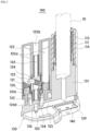
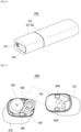
- a heater assembly 100 for a cigarette-shaped electronic cigarette may be applied to a cigarette-shaped electronic cigarette 200 which generates smoking vapor by heating a cigarette 10 produced as a solid stick.
- the cigarette-shaped electronic cigarette 200 may generate not only smoking vapor including nicotine but also smoky vapor, thereby emitting vapor in an amount that is greater than or equal to an amount of smoke generated during smoking of an actual cigarette.
- the heater assembly 100 for a cigarette-shaped electronic cigarette includes a smoking vapor generation part 110 and a smoky vapor generation part 120.
- the smoking vapor generation part 110 may heat the cigarette 10 to generate smoking vapor including nicotine.
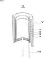
- the smoking vapor generation part 110 may include a first heater 111 configured to heat the cigarette 10 when power is applied.
- the first heater 111 may be formed to have a hollow cylindrical shape of which upper and lower portions are open such that a portion of the cigarette 10 is insertable thereinto.
- the cigarette 10 inserted into a hollow portion may be heated through heat that is generated and supplied by the first heater 111. Since an entire circumferential surface of the cigarette 10 may be heated, a heated area of the cigarette 10 may be widened, and concurrently, an entirety of the cigarette 10 may be uniformly heated.
- the first heater 111 may have a form in which a known heater is formed in a cylindrical shape. Meanwhile, in order to increase reliability and a life cycle of a product and rapidly move heat generated from a heat generating source under operating conditions in which heating and cooling are repeatedly performed, the first heater 111 may include a ceramic material.
- the first heater 111 may include a support 111a, an electrode pattern 111b, and a protective layer 111c.
- the support 111a may be made of a ceramic material, and the electrode pattern 111b may be patterned and formed on one surface of the support 111a.
- heat generated in the electrode pattern 111b when power is applied may be moved to the support 111a made of a ceramic material and then may be rapidly transferred to an entire area of the support 111a.
- the first heater 111 may widen a heated area and concurrently uniformly heat an entirety of the heated area.
- the support 111a may be made of a ceramic material having a heat resisting property to withstand a high temperature of 100 °C or more when the electrode pattern 111b generates heat.
- the support 111a may be made of a ceramic material such as alumina (Al 2 O 3 ), magnesium oxide (MgO), silicon nitride (Si 3 N 4 ), silicon carbide (SiC), aluminum nitride (AlN), or the like, but the present invention is not limited thereto. Any known ceramic material may be applied.
- the material of the support 111a is not limited thereto, and any material may be applied as long as the material may have an insulating property and a heat resisting property to prevent a short circuit with the electrode pattern 111b and to withstand a high temperature of 100 °C or more when the electrode pattern 111b generates heat.
- the electrode pattern 111b may serve as a heating element which generates heat when power is applied.
- the electrode pattern 111b may be patterned and formed on one surface of the support 111a.
- the electrode pattern 111b may be a printed pattern formed through a conductive paste or may have a form of a conductive member which is patterned and formed through shape processing such as etching or punching and attached to the support 111a.
- the conductive paste may be silver (Ag), tungsten, molybdenum, or a mixed component thereof but is not limited thereto.
- any known electrode material may be used that is appropriately selected according to a heat-generating temperature required when power is applied.
- the protective layer 111c may be made of a material having an insulating property to prevent the electrode pattern 111b from being externally exposed and also to prevent the electrode pattern 111b from being shorted with other components.
- the protective layer 111c may also have a heat resisting property and a thermosetting property to be prevented from being destroyed by heat generated from the electrode pattern 111b.
- the protective layer 111c may be a coating layer which is made of a resin having an insulating property, a thermosetting property, and a heat resisting property and is applied at a certain thickness on at least one surface of the support 111a. Accordingly, the electrode pattern 111b may be blocked from being externally exposed through the protective layer 111c.
- the protective layer 111c may be a coating layer made of liquid polyimide or polyamideimide, but the present invention is not limited thereto. Any known material may be used as long as the material has an insulating property, a thermosetting property, and a heat resisting property.
- the protective layer 111c may be formed only on one surface of the support 111a to cover the electrode pattern 111b or may also be formed to cover both surfaces of the support 111a. Accordingly, even when the support 111a is made of a ceramic material having high brittleness, an impact caused by an external force may be absorbed through the protective layer 111c, thereby preventing the support 111a from being damaged by the external force.
- the first heater 111 may be electrically connected to a circuit board 140 to be described below through a plurality of lead portions 111d, and thus, the electrical operation thereof may be controlled.
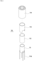
- the smoking vapor generation part 110 may further include a heat insulating member 112, a fixing member 113, and a first cover member 114. As shown in FIG. 2 , the smoking vapor generation part 110 may be detachably coupled to one side of a supporting part 130 through the first cover member 114.
- the heat insulating member 112, the fixing member 113, and the first cover member 114 may be sequentially disposed to surround the first heater 111, and the smoking vapor generation part 110 may be maintained in a state of being coupled to the supporting part 130 through the first cover member 114 detachably coupled to the supporting part 130 or may be separated from the supporting part 130.
- the heat insulating member 112 may be disposed to surround an outer surface of the first heater 111, thereby blocking heat generated in the first heater 111 from being dissipated to the outside or being transferred to other peripheral components.
- heat generated in the first heater 111 may be concentrated in the first heater 111 and may be concentrated to the cigarette 10 inserted into the hollow portion of the first heater 111.
- any heat insulating material that is typically used may be applied to the heat insulating member 112.
- the heat insulating member 112 may include a graphite material to reduce the heat generated in the first heater 111 being dissipated in a radial direction of the first heater 111 and to facilitate a heat transfer in a horizontal direction perpendicular to the radial direction.
- the heat insulating member 112 may include a first sheet 112a and a second sheet 112b which have a certain area and are attached to each other.
- any one of the first sheet 112a and the second sheet 112b may be a plate-shaped graphite sheet, and the other thereof may be a polyimide (PI) film member.
- PI polyimide
- a graphite sheet has a high heat transfer rate in a horizontal direction corresponding to a length or width direction thereof but has a very low heat transfer rate in a vertical direction corresponding to a thickness direction thereof.
- the heat insulating member 112 may be disposed outside the first heater 111 in consideration of the above-described heat transfer characteristics of the graphite sheet.
- the heat insulating member 112 may have a form in which a plate-shaped graphite sheet and a PI film member are attached to each other.
- the heat insulating member 112 may be disposed outside the first heater 111 such that a thickness direction of the graphite sheet is parallel to the radial direction of the first heater 111. Accordingly, the heat insulating member 112 may minimize the heat generated in the first heater 111 being dissipated to the outside, thereby concentrating the heat generated in the first heater 111 to the first heater 111.
- the heat generated in the first heater 111 is transferred to the heat insulating member 112
- the heat may be prevented from being dissipated to the outside due to the graphite sheet having a low heat transfer rate in a thickness direction thereof.
- the heat transferred to the graphite sheet may be dispersed in a horizontal direction so that the graphite sheet may serve to insulate the first heater 111.
- a portion of the heat transferred to the graphite sheet may be secondarily blocked from being moved by the PI film member, thereby securing a more excellent heat insulating property.
- the heat insulating member 112 may be attached to the outer surface of the first heater 111 through an adhesive layer and may also be fixed through the hollow fixing member 113.
- the heat insulating member 112 may be wound one or more times to cover the outer surface of the first heater 111 in a circumferential direction of the first heater 111.
- the heat insulating member 112 may be fixed through the fixing member 113 surrounding the heat insulating member 112.
- the heat insulating member 112 may be disposed between the first heater 111 and the fixing member 113, and both surfaces of the heat insulating member 112 may be maintained in a state of being in contact with the outer surface of the first heater 111 and an inner surface of the fixing member 113.
- the fixing member 113 may be made of a material having rigidity to perform a function of protecting the first heater 111 as well as a function of fixing the heat insulating member 112 such that the heat insulating member 112 is maintained in a state of being pressed against the outer surface of the first heater 111.
- the fixing member 113 may be made of a metal material.
- a lower edge of the fixing member 113 may be supported by one side of the supporting part 130.
- One side of the first cover member 114 may be coupled to the supporting part 130.
- the first cover member 114 may protect the fixing member 113 and the first heater 111 from an external environment and may also maintain mounting positions of the fixing member 113 and the first heater 111.
- the first cover member 114 may be formed to have a hollow form to wrap the fixing member 113, and a region of the first cover member 114 corresponding to the hollow portion of the first heater 111 may be open such that the cigarette 10 inserted from the outside enters into the first heater 111.
- a lower portion of the first cover member 114 may be detachably coupled to the supporting part 130.
- a component requiring replacement may be easily replaced by separating the first cover member 114 from the supporting part 130.
- a gap d may be formed between an inner surface of the first cover member 114 and an outer surface of the fixing member 113 which face each other.
- the gap d may be formed in a height direction of the fixing member 113.
- an air layer may be formed in the gap d.
- the air layer formed in the gap d may implement a heat insulating effect.
- the heat generated in the first heater 111 may be blocked twice from being transferred in a direction parallel to the radial direction of the first heater 111 through the heat insulating member 112 and the air layer.
- the heat generated in the first heater 111 may be further concentrated to the hollow portion of the first heater 111, and a raise in temperature of the first cover member 114 may be minimized.
- the smoky vapor generation part 120 may generate smoky vapor not including nicotine during smoking and may supply the smoky vapor to the smoking vapor generation part 110.
- a user may inhale smoking vapor generated from the cigarette 10 inserted into the smoking vapor generation part 110 and smoky vapor generated in the smoky vapor generation part 120 together.
- the user may additionally inhale and then exhale the smoky vapor not including nicotine generated in the smoky vapor generation part 120 together with the smoking vapor including nicotine generated in the smoking vapor generation part 110.
- the user may inhale and exhale vapor in an abundant amount greater than or equal to an amount of smoke generated during smoking using a typical cigarette, and thus, it is possible to increase satisfaction with smoking.
- the smoky vapor generation part 120 may include a second cover member 122 which has a storage space 122a for storing a liquid material converted into smoky vapor when being heated, and a second heater 121 which vaporizes the liquid material introduced from the storage space 122a to generate the smoky vapor.
- the smoky vapor generation part 120 may include an absorption member 123 which supplies the liquid material stored in the storage space 122a to the second heater 121.
- the liquid material when power is supplied to the second heater 121, the liquid material may be supplied to the second heater 121 through the absorption member 123.
- the liquid material supplied to the second heater 121 may be vaporized through heat supplied from the second heater 121.
- the smoky vapor generation part 120 may generate the smoky vapor.
- the liquid material may not include nicotine and may be a material vaporized at a temperature of 100 °C or less.
- the liquid material may be a liquid material including glycerin but is not limited thereto. Any liquid material may be applied as long as the material may be vaporized at a temperature of 300 °C or lower, and preferably, at a temperature of 100 °C or less.
- the liquid material may also include a nicotine material used to generate smoking vapor in a typical electronic cigarette.
- the absorption member 123 may be a glass fiber, cotton, or a fabric, but the material of the absorption member 123 is not limited thereto. Any material may be applied as long as the material may smoothly absorb a liquid material.
- the second heater 121 may be a coil member wound a plurality of times in a length direction of the absorption member 123.
- the smoky vapor generation part 120 may be disposed to be parallel with the smoking vapor generation part 110, and smoky vapor generated through the second heater 121 may be supplied to the smoking vapor generation part 110.
- the heater assembly 100 for a cigarette-shaped electronic cigarette may include the supporting part 130 to which the smoking vapor generation part 110 and the smoky vapor generation part 120 are coupled.
- the smoking vapor generation part 110 and the smoky vapor generation part 120 may be coupled to one side of the supporting part 130 in parallel.
- the smoky vapor generation part 120 may be provided in a form fixed to the supporting part 130.
- a liquid material may be replenished through an inlet or the like (not shown) communicating with the storage space 122a.
- the smoky vapor generation part 120 may be detachably coupled to the supporting part 130.
- the smoky vapor generation part 120 itself may be replaced by separating the smoky vapor generation part 120 from the supporting part 130.
- the heater assembly 100 for a cigarette-shaped electronic cigarette according to one exemplary embodiment of the present invention, it is possible to eliminate the need to inject a liquid material, and it is possible to increase reliability and stability of a product by inducing a user to use the smoky vapor generation part 120 including a prescribed liquid material.
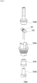
- the smoky vapor generation part 120 may have a module form which further includes a body 124 and a coupling member 126 in addition to the second cover member 122, the absorption member 123, and the second heater 121.
- the smoky vapor generation part 120 may be detachably coupled to one side of the supporting part 130 through the coupling member 126.
- the body 124 may have an air passage 125 formed to pass through the body 124 in a length direction thereof such that outside air passes through the air passage 125.
- the body 124 may be detachably coupled to the coupling member 126.
- the second cover member 122 may be detachably coupled to the coupling member 126 to surround at least a portion of the body 124.
- the storage space 122a may be defined through the coupling member 126 and the body 124, and an inlet passage 122b for introducing outside air may be formed in a height direction of the body 124 so as to be connected to the air passage 125 formed in the body 124 (see FIG. 3 ).
- the second heater 121 and the absorption member 123 may be disposed in the air passage 125.
- the second heater 121 may be disposed in a form which is wound a plurality of times in the length direction of the absorption member 123.
- the absorption member 123 may be fixed to the body 124 such that both end portions thereof protrude to the storage space 122a to smoothly absorb the liquid material stored in the storage space 122a.
- the coupling member 126 may be formed to have a hollow form such that the body 124 and the second cover member 122 are detachably coupled to an inner surface and an outer surface thereof.
- a flange 126a protruding outward may be formed at a lower edge of the coupling member 126.
- the coupling member 126 may be installed to be caught on a latch portion 137 formed to protrude from one surface of the supporting part 130.
- the body 124 may have a form in which a plurality of members are coupled to each other.
- the body 124 may include a first body 124a, a second body 124b, an insulating member 124c, and a first electrode member 124d.
- the first body 124a may be provided in a hollow form of which upper and lower portions are open.
- the second body 124b may be coupled to an upper portion of the first body 124a.
- the insulating member 124c to which the first electrode member 124d is coupled may be coupled to a lower portion of the first body 124a.
- hollow portions of the second body 124b, the first body 124a, and the first electrode member 124d may communicate with each other to form the air passage 125.
- Both end portions of the absorption member 123 on which the second heater 121 is wound may be fixed to the first body 124a when the first body 124a and the second body 124b are coupled to each other.
- first body 124a, the first electrode member 124d, and the coupling member 126 may be made of a conductive material such as a metal, and both end portions of a coil constituting the second heater 121 may connected to the first body 124a and the first electrode member 124d.
- the second heater 121 may be electrically connected through two electrode members 138 and 150 provided in the supporting part 130.
- the present invention is not limited thereto, and the body may have a form in which an appropriate number of members are coupled to each other or may be one hollow member in which an air passage is formed in a length direction thereof.
- the body when the body is formed as one member, the body may have a form in which two through-holes are formed in the body in a direction perpendicular to the air passage 125 and both end portions of the absorption member 123 are inserted into and then fixed in the through-holes.
- the configuration of the smoky vapor generation part 120 is not limited to the above-described structure, and the detailed configuration of the smoky vapor generation part 120 may be appropriately modified according to design conditions as long as the smoky vapor generation part 120 may use a method in which the liquid material supplied from the storage space 122a is heated through the second heater 121 to generate smoky vapor.
- the supporting part 130 may support the smoking vapor generation part 110 and the smoky vapor generation part 120.
- the smoking vapor generation part 110 and the smoky vapor generation part 120 may each be detachably coupled to the supporting part 130.
- the smoking vapor generation part 110 and the smoky vapor generation part 120 may each be coupled onto a horizontal surface of the supporting part 130.
- the smoking vapor generation part 110 and the smoky vapor generation part 120 may be coupled to portions protruding from the horizontal surface by a certain height so as to prevent smoky vapor generated through the second heater 121 from leaking to the outside and to increase coupling performance.
- the supporting part 130 may include a first protrusion 131 in a hollow form and a second protrusion 132 in a hollow form which extend upward from one surface thereof by a certain height.
- a lower portion of the first cover member 114 may be coupled to the first protrusion 131, and a lower edge of the fixing member 113 may be supported by an upper edge of the first protrusion 131.
- the second protrusion 132 may be inserted into a lower portion of the coupling member 126. Therefore, the inside of the second protrusion 132 may communicate with the air passage 125.
- the first electrode member 124d may have a cutout groove 124e which is recessed from a lower portion to an inner side thereof. Accordingly, air moving in a length direction or height direction of the first electrode member 124d may move in a horizontal direction through the cutout groove 124e and thus be introduced into the second protrusion 132.
- a second electrode member 150 may be provided in the second protrusion 132 in order for an electrical connection with the second heater 121 when the smoky vapor generator 120 and the supporting part 130 are coupled to each other.
- an electrode arrangement hole 136 for placing the second electrode member 150 may be formed to pass through the second protrusion 132, and the second electrode member 150 may be detachably inserted into the electrode arrangement hole 136. Accordingly, when the smoky vapor generation part 120 is coupled to the second protrusion 132, a lower end of the first electrode member 124d included in the smoky vapor generation part 120 may be in contact with the second electrode member 150, and the first electrode member 124d and the second electrode member 150 may be electrically connected to each other through the contact.
- a contact electrode 138 may be provided on one surface of the supporting part 130 to be externally exposed in a region corresponding to the lower edge of the coupling member 126 when the smoky vapor generation part 120 is coupled to the second protrusion 132.
- the coupling member 126 made of a conductive material and the contact electrode 138 may be in contact with each other.
- the coupling member 126 and the contact electrode 138 may be electrically connected to each other.
- the contact electrode 138 may be a ball plunger, and the second electrode member 150 and the contact electrode 138 may be electrically connected to a main substrate 231 constituting a control part of the cigarette-shaped electronic cigarette 200.
- smoking vapor generated in the smoking vapor generation part 110 and smoky vapor generated in the smoky vapor generation part 120 may be concurrently supplied to the user.
- smoking vapor and the smoky vapor may be supplied to the user by a suction force of the user.
- the supporting part 130 may include a movement passage 133 through which the smoky vapor generated in the smoky vapor generation part 120 is moved to the smoking vapor generation part 110.
- the movement passage 133 may be formed inside the supporting part 130, and the movement passage 133 may connect the inside of the first protrusion 131 and the inside of the second protrusion 132.
- a communication passage 134 may be formed in a bottom surface of the second protrusion 132 and connected to the movement passage 133.
- the smoky vapor generated in the smoky vapor generation part 120 may be moved downward along the air passage 125 by the suction force of the user and then may be moved to a hollow portion of the second protrusion 132 through the cutout groove 124e formed in the first electrode member 124d.
- the smoky vapor moved to the hollow portion of the second protrusion 132 may be introduced into the smoking vapor generation part 110 via the communication passage 134 and the movement passage 133.
- the smoky vapor may be combined with the smoking vapor generated in the smoking vapor generation part 110 and may be discharged to the outside together with the smoking vapor through the cigarette.
- the user may concurrently inhale the smoking vapor and the smoky vapor.
- an amount of the exhaled vapor may be increased by an amount which is as much as an amount corresponding to the smoky vapor.
- an abundant amount of vapor may be discharged to the outside, thereby increasing user satisfaction with smoking.
- a method of supplying the smoky vapor is not limited thereto, and the smoky vapor generated in the smoky vapor generation part 120 may also be supplied to a path, to which smoking vapor is supplied, through other methods.
- the inlet passage 122b which is formed in the height direction in the smoky vapor generation part 120 such that outside air is introduced therethrough, may be connected to the air passage 125.
- the smoky vapor generated in the smoky vapor generation part 120 may be smoothly moved to the smoking vapor generation part 110 through the movement passage 133 by the suction force of the user.
- the circuit board 140 electrically connected to the first heater 111 may be disposed on one surface of the supporting part 130.
- the circuit board 140 may be fixed to the supporting part 130.
- the supporting part 130 may include an accommodation groove 139 formed to be recessed from one surface thereof to accommodate the circuit board 140, and the circuit board 140 may be fitted into and disposed in the accommodation groove 139.
- the plurality of lead portions 111d protruding from the first heater 111 to have a certain length may be connected to the circuit board 140.
- the circuit board 140 may be electrically connected to the main substrate 231 constituting the control part of the cigarette-shaped electronic cigarette 200 through a separate case (not shown).
- lead portion arrangement holes 135 through which the plurality of lead portions 111d pass may be formed to pass through the supporting part 130. Accordingly, the lead portions 111d inserted into the lead portion arrangement holes 135 may be protected from an external force through the supporting part 130.
- the lead portions 111d may be prevented from being disconnected from the circuit board 140.
- various problems such as electrical disconnection may be solved, and reliability of a product may be improved.
- the heater assembly 100 for a cigarette-shaped electronic cigarette may be implemented into the cigarette-shaped electronic cigarette 200.
- the cigarette-shaped electronic cigarette 200 may include the heater assembly 100 for a cigarette-shaped electronic cigarette, a case 210, the control part, and a power supply part 220.
- the heater assembly 100 may be accommodated inside the case 210 together with the control part and the power supply part 220 and may use power provided from the power supply part 220 as driving power. That is, in the heater assembly 100, the first heater 111 and the second heater 121 may be operated by driving of the control part, and smoking vapor and smoky vapor may be generated from the cigarette inserted into the smoking vapor generation part 110 and the liquid material included in the smoky vapor generation part 120, respectively.
- the power supply part 220 may be a known battery, and the battery may be a primary battery or may be a rechargeable secondary battery.
- the control part may have a form in which a chipset 232 such as a main control unit (MCU) is mounted on one surface of the main substrate 231, and the main substrate 231 may include various circuits for electrical or electronic driving.
- MCU main control unit
- the case 210 may include a first case 211 configured to accommodate the smoking vapor generation part 110 and the smoky vapor generation part 120 therein and a second case 212 configured to accommodate the control part and the power supply part 220 therein.
- the supporting part 130 may be detachably fixed to an upper edge of the second case 212.
- a pair of magnet members 160 and 240 corresponding to each other may be provided in the first case 211 and the supporting part 130. Accordingly, the pair of magnet members 160 and 240 may provide a binding force caused by a magnetic force, and the first case 211 may be prevented from being easily separated from the second case 212 through the binding force.
- the shape of the case 210 is not limited thereto, and the case 210 may be formed as one member.
- the first case 211 may include an inlet 213 formed to pass through a region corresponding to the smoking vapor generation part 110.
- the cigarette 10 when the cigarette 10 is inserted into the inlet 213, the cigarette 10 may be inserted into the hollow portion of the first heater 111 formed to have a hollow form and may be heated by heat generated in the first heater 111.
- the case 210 may further include a cover member 250 for opening or closing the inlet 213.
- the cover member 250 may close the open inlet 213 to prevent the first heater 111 from being externally exposed. Accordingly, the first heater 111 may be prevented from being contaminated from an external environment.
- the cover member 250 may be implemented in a sliding manner in which the cover member 250 reciprocates along one surface of the case 210, but the present invention is not limited thereto. All various known manners such as a hinge manner and an insertion manner may be applied as long as the cover member 250 may have a form which seals the inlet 213.
- a charging port 260 for recharging the power supply part 220 may be externally exposed from one side of the case 210.
- the charging port 260 may be mounted on the main substrate 231.
- the charging port 260 may be a known Universal Serial Bus (USB) connector, and a known charging cable may be connected thereto.
- USB Universal Serial Bus
- the charging port 260 may be connected to an external power supply source through a charging cable to receive power, and thus, the power supply part 220 may be recharged.
- the cigarette-shaped electronic cigarette 200 may include a notification part which outputs a certain signal such that a user recognizes a variety of information such as turn-on/off, an operating time of the first and second heaters 111 and 121, and a smokable state or a non-smokable state.
- the notification part may be a vibration motor 270 which is electrically connected to the control part to generate a vibration when a notification is required.
- the present invention is not limited thereto, and the notification part may use a method of outputting a sound, a method of displaying a text, a method of turning on/off a light, or a method in which two or more methods are combined with each other.
- the cigarette-shaped electronic cigarette 200 may have a wireless communication function of transmitting and receiving information related to a state of a device or smoking such as the number of instances of inhalations to and from an external device through wireless communication.
- the wireless communication function may use a Bluetooth or near field communication (NFC) method, but the present invention is not limited thereto. All of various known wireless communication methods may be applied.
Landscapes
- Health & Medical Sciences (AREA)
- Engineering & Computer Science (AREA)
- Animal Behavior & Ethology (AREA)
- Veterinary Medicine (AREA)
- Public Health (AREA)
- General Health & Medical Sciences (AREA)
- Anesthesiology (AREA)
- Biomedical Technology (AREA)
- Heart & Thoracic Surgery (AREA)
- Hematology (AREA)
- Life Sciences & Earth Sciences (AREA)
- Pulmonology (AREA)
- Chemical & Material Sciences (AREA)
- Bioinformatics & Cheminformatics (AREA)
- Ceramic Engineering (AREA)
- Resistance Heating (AREA)
- Physical Vapour Deposition (AREA)
- General Preparation And Processing Of Foods (AREA)
- Manufacture Of Tobacco Products (AREA)
- Catching Or Destruction (AREA)
Claims (12)
- Heizeinheit (100) für eine zigarettenförmige elektronische Zigarette (200), die Folgendes aufweist:ein Teil zur Rauchdampferzeugung (110), das ein erstes Heizelement (111) enthält, das so konfiguriert ist, dass es Rauchdampf durch Erhitzen eines Teils einer darin eingeführten Zigarette (10) erzeugt; undein Teil zur Erzeugung eines rauchigen Dampfes (120), der ein zweites Heizelement (121) umfasst, das so konfiguriert ist, dass es rauchigen Dampf durch Erhitzen eines flüssigen Materials erzeugt, wenn an der Zigarette (10) gepafft wird;wobei der rauchige Dampf durch eine Saugkraft, die erzeugt wird, wenn an der Zigarette (10) gepafft wird, durch die Zigarette (10) hindurchgeht und dann gleichzeitig mit dem Rauchdampf inhaliert wird, wobei der Teil zur Rauchdampferzeugung (110) Folgendes umfasst:das erste Heizelement (111);ein wärmeisolierendes Teil (112), das so angeordnet ist, dass es eine Außenfläche des ersten Heizelements (111) umgibt; unddadurch gekennzeichnet, dass ein Befestigungsteil (113) angebracht ist, um eine Außenfläche des wärmeisolierenden Teils (112) zu umgeben und das wärmeisolierende Teil (112) gegen die Außenfläche des ersten Heizelements (111) zu drücken.
- Die Heizeinheit (100) nach Anspruch 1, die außerdem Folgendes aufweist:ein Stützteil (130), mit dem sowohl das Teil zur Rauchdampferzeugung (110) als auch das Teil zur Erzeugung eines rauchigen Dampfes (120) gekoppelt ist,wobei das Stützteil (130) einen Bewegungsdurchlass (133) inkludiert, durch den der in dem Teil zur Erzeugung eines rauchigen Dampfes (120) erzeugte rauchige Dampf zu dem Teil zur Rauchdampferzeugung (119) bewegt wird,wobei das Stützteil (130) einen Vorsprung (132) in einer hohlen Form inkludiert, der in eine Richtung vorsteht und mit dem das Teil zur Erzeugung eines rauchigen Dampfes (120) gekoppelt ist, und ein Kommunikationsdurchlass (134) in einer Bodenfläche des Vorsprungs (132) ausgebildet und mit dem Bewegungsdurchlass (133) verbunden ist.
- Die Heizeinheit (100) nach Anspruch 2, wobei der Teil zur Erzeugung eines rauchigen Dampfes (120) lösbar mit dem Stützteil (130) verbunden ist.
- Die Heizeinheit (100) nach Anspruch 2, wobei zur Aufnahme einer Leiterplatte (140) eine Aufnahmerille (139) in einer Oberfläche des Stützteils (130) gebildet wird, und die Leiterplatte (140) ist mit dem ersten Heizelement (111) elektrisch verbunden.
- Die Heizeinheit (100) nach Anspruch 1, wobei das erste Heizelement (111) so geformt ist, dass es eine hohlzylindrische Form hat, deren oberer und unterer Teil offen sind, sodass der Zigarettenabschnitt (10) darin eingeführt werden kann, und
das erste Heizelement (111) eine Außenfläche der Zigarette (10) erwärmt. - Die Heizeinheit (100) nach Anspruch 5, wobei das erste Heizelement (111) Folgendes inkludiert:eine Halterung (111a), die aus einem keramischen Material besteht und eine hohle Form aufweist;ein Elektrodenmuster (111b), das auf einer Oberfläche der Halterung (111a) gebildet ist, um Wärme zu erzeugen; undeine Schutzschicht (111c), die eine isolierende Eigenschaft und eine wärmeisolierende Eigenschaft hat und das Elektrodenmuster (11 1b) bedeckt.
- Die Heizeinheit (100) nach Anspruch 1, wobei das wärmeisolierende Teil (112) ein Graphitmaterial beinhaltet, um zu verhindern, dass in dem ersten Heizelement (111) erzeugte Wärme in radialer Richtung des ersten Heizelements (111) abgeleitet wird.
- Die Heizeinheit (100) nach Anspruch 1, wobei der Teil zur Rauchdampferzeugung (110) ein erstes Abdeckelement (114) inkludiert, das außerhalb des Befestigungsteils (113) angeordnet ist, und
ein Spalt (d) zwischen einer Innenfläche des ersten Abdeckelements (114) und einer Au-ßenfläche des Befestigungsteils (113), die einander zugewandt sind, in einer Höhenrichtung des Befestigungsteils (113) gebildet wird. - Die Heizeinheit (100) nach Anspruch 1, wobei der Teil zur Erzeugung eines rauchigen Dampfes (120) inkludiert:einen Körper (124) mit einem Luftdurchlass (125), der in einer Längsrichtung des Körpers (124) ausgebildet ist, sodass Außenluft durch den Luftdurchlass (125) strömt;ein Kupplungselement (126), das mit dem Gehäuse (124) verbunden ist;ein zweites Abdeckelement (122), das mit dem Kupplungselement (126) verbunden ist, um einen Stauraum (122a) zu bilden, in dem das flüssige Material in einer bestimmten Menge untergebracht ist;ein Absorptionsteil (123), das in dem Luftdurchlass (125) angeordnet ist, um das aus dem Stauraum (122a) eingeführte flüssige Material zu absorbieren; undein zweites Heizelement (121), das mehrmals in einer Längsrichtung des Absorptionsteils (123) gewickelt ist, um den rauchigen Dampf durch Verdampfen des vom Absorptionsteil (123) absorbierten flüssigen Materials zu erzeugen, wenn Strom angelegt wird.
- Eine zigarettenförmige elektronische Zigarette (200), die Folgendes aufweist:die Heizeinheit (100) nach einem der Ansprüche 1 bis 9;eine Umkleidung (210), die einen Einlass (213) zum Einführen der Zigarette (10) in einen Bereich aufweist, der dem Teil zur Rauchdampferzeugung (110) entspricht und in den die Heizeinheit (100) eingebettet ist;ein Steuerteil, das innerhalb der Umkleidung (210) angeordnet ist, um einen Gesamtbetrieb der Heizeinheit (100) zu steuern; undein Stromversorgungsteil (220), das so konfiguriert ist, dass es dem Steuerteil Antriebsenergie zuführt.
- Die zigarettenförmige elektronische Zigarette (200) nach Anspruch 10, wobei die Umkleidung (210) ein Abdeckelement (250) inkludiert, das zum Öffnen oder Schließen des Einlasses (213) konfiguriert ist.
- Die zigarettenförmige elektronische Zigarette (200) nach Anspruch 10, wobei ein Ladeanschluss (260), der zum Aufladen des Stromversorgungsteils (220) konfiguriert ist, an einer Seite der Umkleidung (210) vorgesehen ist.
Applications Claiming Priority (2)
| Application Number | Priority Date | Filing Date | Title |
|---|---|---|---|
| KR1020170092705A KR102116961B1 (ko) | 2017-07-21 | 2017-07-21 | 궐련형 전자담배용 히터조립체 및 이를 포함하는 궐련형 전자담배 |
| PCT/KR2018/007944 WO2019017654A2 (ko) | 2017-07-21 | 2018-07-13 | 궐련형 전자담배용 히터조립체 및 이를 포함하는 궐련형 전자담배 |
Publications (4)
| Publication Number | Publication Date |
|---|---|
| EP3656229A2 EP3656229A2 (de) | 2020-05-27 |
| EP3656229A4 EP3656229A4 (de) | 2021-04-14 |
| EP3656229C0 EP3656229C0 (de) | 2024-11-06 |
| EP3656229B1 true EP3656229B1 (de) | 2024-11-06 |
Family
ID=65015977
Family Applications (1)
| Application Number | Title | Priority Date | Filing Date |
|---|---|---|---|
| EP18836153.9A Active EP3656229B1 (de) | 2017-07-21 | 2018-07-13 | Heizeranordnung für zigarettenförmige elektronische zigarette und zigarettenförmige elektronische zigarette damit |
Country Status (6)
| Country | Link |
|---|---|
| US (2) | US11044941B2 (de) |
| EP (1) | EP3656229B1 (de) |
| JP (2) | JP2020527955A (de) |
| KR (1) | KR102116961B1 (de) |
| CN (1) | CN110944531B (de) |
| WO (1) | WO2019017654A2 (de) |
Families Citing this family (84)
| Publication number | Priority date | Publication date | Assignee | Title |
|---|---|---|---|---|
| KR20180124739A (ko) | 2017-05-11 | 2018-11-21 | 주식회사 케이티앤지 | 궐련의 종류별로 에어로졸 생성장치에 포함된 히터의 온도를 제어하는 방법 및 궐련의 종류별로 히터의 온도를 제어하는 에어로졸 생성장치 |
| RU2728109C1 (ru) | 2017-05-11 | 2020-07-28 | Кей Ти Энд Джи Корпорейшн | Испаритель и устройство для генерирования аэрозоля, содержащее такой испаритель |
| KR102116961B1 (ko) * | 2017-07-21 | 2020-06-02 | 주식회사 아모센스 | 궐련형 전자담배용 히터조립체 및 이를 포함하는 궐련형 전자담배 |
| KR20190049391A (ko) | 2017-10-30 | 2019-05-09 | 주식회사 케이티앤지 | 히터를 구비한 에어로졸 생성 장치 |
| CN110996693B (zh) | 2017-10-30 | 2023-01-24 | 韩国烟草人参公社 | 气溶胶生成装置、加热器及制作气溶胶生成装置用加热器的方法 |
| KR102138246B1 (ko) | 2017-10-30 | 2020-07-28 | 주식회사 케이티앤지 | 증기화기 및 이를 구비하는 에어로졸 생성 장치 |
| EP3704963B1 (de) | 2017-10-30 | 2024-05-29 | KT&G Corporation | Optisches modul und aerosolgenerator damit |
| KR102180421B1 (ko) | 2017-10-30 | 2020-11-18 | 주식회사 케이티앤지 | 에어로졸 생성 장치 |
| WO2019088559A2 (ko) | 2017-10-30 | 2019-05-09 | 주식회사 케이티앤지 | 에어로졸 생성 장치 |
| KR102138245B1 (ko) | 2017-10-30 | 2020-07-28 | 주식회사 케이티앤지 | 에어로졸 생성 장치 |
| EP4008204A1 (de) | 2017-10-30 | 2022-06-08 | KT&G Corporation | Aerosolerzeugungsvorrichtung und verfahren zur steuerung davon |
| KR102057216B1 (ko) | 2017-10-30 | 2019-12-18 | 주식회사 케이티앤지 | 에어로졸 생성 장치 및 에어로졸 생성 장치용 히터 조립체 |
| KR102057215B1 (ko) | 2017-10-30 | 2019-12-18 | 주식회사 케이티앤지 | 에어로졸 생성 장치 및 생성 방법 |
| WO2019088580A2 (ko) | 2017-10-30 | 2019-05-09 | 주식회사 케이티앤지 | 에어로졸 생성 장치 |
| CN115530429A (zh) | 2017-10-30 | 2022-12-30 | 韩国烟草人参公社 | 气溶胶生成装置 |
| KR102274248B1 (ko) | 2018-04-24 | 2021-07-07 | 주식회사 아모센스 | 궐련형 전자담배장치용 히터조립체 및 이를 포함하는 궐련형 전자담배장치 |
| KR102096065B1 (ko) | 2018-06-05 | 2020-04-01 | 주식회사 케이티앤지 | 에어로졸 생성 장치 |
| US11399566B2 (en) | 2018-06-05 | 2022-08-02 | Kt&G Corporation | Aerosol generating device |
| KR102203851B1 (ko) * | 2018-11-12 | 2021-01-15 | 주식회사 케이티앤지 | 에어로졸 생성 장치 및 이를 제어하는 방법 |
| CN109602091B (zh) * | 2019-01-17 | 2023-09-15 | 云南中烟工业有限责任公司 | 一种支持多抽吸模式的雾化装置及其使用方法 |
| JP7303316B2 (ja) * | 2019-01-26 | 2023-07-04 | 深▲せん▼市合元科技有限公司 | 巻きタバコ加熱器及び電気加熱式の喫煙具 |
| KR102012849B1 (ko) * | 2019-02-25 | 2019-08-21 | 주식회사 케이티앤지 | 에어로졸 생성 장치 |
| CN119563937A (zh) | 2019-05-14 | 2025-03-07 | 深圳麦克韦尔科技有限公司 | 电子雾化装置 |
| CN210538906U (zh) | 2019-05-14 | 2020-05-19 | 深圳麦克韦尔科技有限公司 | 电子雾化装置 |
| KR102400046B1 (ko) * | 2019-08-02 | 2022-05-19 | 주식회사 케이티앤지 | 히터 조립체 및 이를 포함하는 에어로졸 발생 장치 |
| CN110623305A (zh) * | 2019-09-05 | 2019-12-31 | 深圳麦克韦尔科技有限公司 | 一种气雾产生装置、发热组件以及数据交互方法 |
| FR3102342A1 (fr) * | 2019-10-23 | 2021-04-30 | Thierry CAI | Cigarette electronique a fixation par aimantation |
| KR20210052737A (ko) | 2019-10-30 | 2021-05-11 | (주) 에프원케이티 | 착탈식 흡연 디바이스 |
| KR102381037B1 (ko) * | 2019-12-20 | 2022-03-31 | 주식회사 이엠텍 | 미세입자 발생장치의 히팅 파이프 조립 구조 |
| CN113080522A (zh) * | 2020-01-08 | 2021-07-09 | 深圳市合元科技有限公司 | 气雾生成装置 |
| WO2021170833A1 (en) * | 2020-02-28 | 2021-09-02 | Jt International Sa | Heater arrangement |
| KR102455535B1 (ko) * | 2020-06-16 | 2022-10-17 | 주식회사 케이티앤지 | 에어로졸 생성 장치 및 그 동작 방법 |
| KR102487083B1 (ko) * | 2020-07-01 | 2023-01-10 | 주식회사 케이티앤지 | 서셉터 조립체를 포함하는 에어로졸 생성 장치 |
| JP7610362B2 (ja) | 2020-07-08 | 2025-01-08 | 日本たばこ産業株式会社 | エアロゾル生成装置の制御ユニット |
| JP7610361B2 (ja) | 2020-07-08 | 2025-01-08 | 日本たばこ産業株式会社 | エアロゾル生成装置の制御ユニット |
| US12389949B2 (en) | 2020-07-31 | 2025-08-19 | Kt&G Corporation | Aerosol generating device including an electrode |
| JP6890203B1 (ja) | 2020-09-30 | 2021-06-18 | 日本たばこ産業株式会社 | エアロゾル生成装置の電源ユニット |
| JP6858915B1 (ja) | 2020-09-30 | 2021-04-14 | 日本たばこ産業株式会社 | エアロゾル生成装置の電源ユニット、エアロゾル生成装置 |
| JP6834053B1 (ja) | 2020-09-30 | 2021-02-24 | 日本たばこ産業株式会社 | エアロゾル生成装置の電源ユニット |
| JP6899026B1 (ja) | 2020-09-30 | 2021-07-07 | 日本たばこ産業株式会社 | エアロゾル吸引器の電源ユニット、エアロゾル吸引器、及びエアロゾル吸引システム |
| JP6837594B1 (ja) | 2020-09-30 | 2021-03-03 | 日本たばこ産業株式会社 | エアロゾル吸引器の電源ユニット及びエアロゾル吸引器 |
| JP6834052B1 (ja) | 2020-09-30 | 2021-02-24 | 日本たばこ産業株式会社 | エアロゾル生成装置の電源ユニット |
| KR20230080427A (ko) * | 2020-10-06 | 2023-06-07 | 제이티 인터내셔널 소시에떼 아노님 | 에어로졸 생성 장치 |
| WO2022090156A1 (en) | 2020-10-28 | 2022-05-05 | Philip Morris Products S.A. | Heater tube with thermal insulation and electrical isolation |
| CN116419685A (zh) * | 2020-11-06 | 2023-07-11 | 日本烟草国际股份有限公司 | 气溶胶产生装置、相关组件和控制方法 |
| KR102649316B1 (ko) * | 2020-11-20 | 2024-03-19 | 주식회사 케이티앤지 | 히터 조립체 및 이를 구비한 에어로졸 생성 장치 |
| GB2604976B (en) * | 2020-12-01 | 2025-08-13 | Em Tech Co Ltd | Heater for microparticle generator and installation structure thereof |
| KR102579817B1 (ko) * | 2021-03-02 | 2023-09-15 | 주식회사 케이티앤지 | 에어로졸 생성 장치 |
| KR102607159B1 (ko) * | 2021-03-24 | 2023-11-29 | 주식회사 케이티앤지 | 에어로졸 생성 장치 |
| KR102545833B1 (ko) * | 2021-04-29 | 2023-06-20 | 주식회사 케이티앤지 | 에어로졸 생성 장치 |
| KR102621736B1 (ko) * | 2021-04-29 | 2024-01-04 | 주식회사 케이티앤지 | 카트리지 및 이를 포함하는 에어로졸 생성 장치 |
| KR102713417B1 (ko) * | 2021-05-14 | 2024-10-07 | 주식회사 케이티앤지 | 에어로졸 생성 물품 및 이를 포함하는 에어로졸 생성 장치 |
| KR102589103B1 (ko) * | 2021-05-20 | 2023-10-12 | 주식회사 케이티앤지 | 카트리지 및 이를 포함하는 에어로졸 생성 장치 |
| KR102542023B1 (ko) * | 2021-05-20 | 2023-06-12 | 주식회사 케이티앤지 | 에어로졸 생성 장치 |
| KR102579820B1 (ko) * | 2021-06-25 | 2023-09-15 | 주식회사 케이티앤지 | 카트리지 및 이를 포함하는 에어로졸 생성 장치 |
| CN117460433A (zh) * | 2021-07-21 | 2024-01-26 | 日本烟草产业株式会社 | 气溶胶生成系统 |
| KR102554954B1 (ko) * | 2021-07-21 | 2023-07-12 | 주식회사 케이티앤지 | 에어로졸 생성 장치 |
| KR102589100B1 (ko) * | 2021-07-22 | 2023-10-12 | 주식회사 케이티앤지 | 에어로졸 생성장치 |
| CN113598426A (zh) * | 2021-07-30 | 2021-11-05 | 深圳麦克韦尔科技有限公司 | 加热模块及电子雾化装置 |
| CN113598425A (zh) * | 2021-07-30 | 2021-11-05 | 深圳麦克韦尔科技有限公司 | 调味部件及电子雾化装置 |
| US20240407443A1 (en) * | 2021-10-19 | 2024-12-12 | Kt&G Corporation | Aerosol generating device |
| KR102660874B1 (ko) * | 2021-10-20 | 2024-04-25 | 주식회사 케이티앤지 | 에어로졸 생성 장치 |
| WO2023068678A1 (en) | 2021-10-20 | 2023-04-27 | Kt&G Corporation | Aerosol-generating device |
| KR20240043158A (ko) * | 2021-12-06 | 2024-04-02 | 니뽄 다바코 산교 가부시키가이샤 | 에어로졸 생성 시스템 |
| KR20240042515A (ko) * | 2021-12-06 | 2024-04-02 | 니뽄 다바코 산교 가부시키가이샤 | 에어로졸 생성 시스템 |
| EP4445762A4 (de) | 2021-12-10 | 2025-10-22 | Japan Tobacco Inc | Stromquelleneinheit einer aerosolerzeugungsvorrichtung |
| US11470878B1 (en) * | 2021-12-16 | 2022-10-18 | The Sos Design Company Llc | Dual-chambered, hybrid vaporizer system for cannabis and flavored products |
| CN116491691A (zh) * | 2022-01-18 | 2023-07-28 | 深圳市合元科技有限公司 | 雾化组件及其组装方法、气溶胶生成装置 |
| GB202202870D0 (en) * | 2022-03-02 | 2022-04-13 | Nicoventures Trading Ltd | Aerosol provision device |
| JP7741977B2 (ja) * | 2022-05-12 | 2025-09-18 | 日本たばこ産業株式会社 | エアロゾル生成システム、及びエアロゾル生成システムの製造方法 |
| CN117397877A (zh) * | 2022-07-08 | 2024-01-16 | 深圳市合元科技有限公司 | 气流加热组件及气溶胶生成装置 |
| CN115363270A (zh) * | 2022-07-29 | 2022-11-22 | 深圳麦克韦尔科技有限公司 | 发热体及电子雾化装置 |
| KR20240018830A (ko) * | 2022-08-03 | 2024-02-14 | 주식회사 케이티앤지 | 가열 온도를 제어 가능한 에어로졸 발생 장치 |
| US20260053190A1 (en) * | 2022-09-01 | 2026-02-26 | Kt&G Corporation | Aerosol generating device |
| WO2024075272A1 (ja) * | 2022-10-07 | 2024-04-11 | 日本たばこ産業株式会社 | 加熱シート、加熱アセンブリおよび香味吸引器 |
| CN115670007A (zh) * | 2022-10-25 | 2023-02-03 | 深圳麦克韦尔科技有限公司 | 气溶胶生成装置及气溶胶生成系统 |
| CN115644497A (zh) * | 2022-11-07 | 2023-01-31 | 云南中烟工业有限责任公司 | 一种消除烟气分层感的加香装置及其使用方法 |
| KR20250114939A (ko) * | 2022-12-16 | 2025-07-29 | 니뽄 다바코 산교 가부시키가이샤 | 향미 흡인기 |
| JPWO2024127613A1 (de) * | 2022-12-16 | 2024-06-20 | ||
| JPWO2024127617A1 (de) * | 2022-12-16 | 2024-06-20 | ||
| WO2024136147A1 (en) * | 2022-12-20 | 2024-06-27 | Kt&G Corporation | Aerosol generating device |
| EP4659603A1 (de) * | 2023-02-01 | 2025-12-10 | KT&G Corporation | Heizanordnung für aerosolerzeugungsvorrichtung und aerosolerzeugungsvorrichtung damit |
| KR20250143325A (ko) * | 2023-02-13 | 2025-10-01 | 니뽄 다바코 산교 가부시키가이샤 | 향미 흡입기 및 향미 흡입기의 제조 방법 |
| EP4602948A1 (de) * | 2024-02-15 | 2025-08-20 | Imperial Tobacco Limited | Aerosolerzeugungsvorrichtung |
Family Cites Families (12)
| Publication number | Priority date | Publication date | Assignee | Title |
|---|---|---|---|---|
| IN166122B (de) * | 1985-08-26 | 1990-03-17 | Reynolds Tobacco Co R | |
| JPH0677606A (ja) | 1992-08-28 | 1994-03-18 | Fujitsu Ltd | 光半導体装置 |
| US6615840B1 (en) * | 2002-02-15 | 2003-09-09 | Philip Morris Incorporated | Electrical smoking system and method |
| US20070074734A1 (en) * | 2005-09-30 | 2007-04-05 | Philip Morris Usa Inc. | Smokeless cigarette system |
| KR100844445B1 (ko) | 2007-06-14 | 2008-07-08 | 주식회사 케이티앤지 | 전기식 가열 궐련 |
| KR101265170B1 (ko) * | 2011-04-05 | 2013-05-24 | 이영인 | 전자담배를 위한 니코틴 용액의 수용 용기 및 이를 가진 전자담배 |
| WO2013007020A1 (zh) * | 2011-07-12 | 2013-01-17 | Liu Qiuming | 一种电子烤烟 |
| CA3079706C (en) | 2011-11-21 | 2023-08-01 | Philip Morris Products S.A. | Ejector for an aerosol-generating device |
| MY184211A (en) * | 2014-08-21 | 2021-03-26 | Philip Morris Products Sa | Aerosol-generating device and system |
| KR200495141Y1 (ko) * | 2016-11-24 | 2022-03-11 | 스미스 테크놀로지 씨오., 엘티디. | 비연소 가열식 흡연 장치 및 이의 가열 조립체 |
| CN108851229A (zh) * | 2017-05-15 | 2018-11-23 | 深圳市康尔科技有限公司 | 多个加热元件的雾化器以及具有多个加热元件雾化器的电子烟 |
| KR102116961B1 (ko) * | 2017-07-21 | 2020-06-02 | 주식회사 아모센스 | 궐련형 전자담배용 히터조립체 및 이를 포함하는 궐련형 전자담배 |
-
2017
- 2017-07-21 KR KR1020170092705A patent/KR102116961B1/ko active Active
-
2018
- 2018-07-13 WO PCT/KR2018/007944 patent/WO2019017654A2/ko not_active Ceased
- 2018-07-13 JP JP2020502958A patent/JP2020527955A/ja active Pending
- 2018-07-13 EP EP18836153.9A patent/EP3656229B1/de active Active
- 2018-07-13 CN CN201880047807.7A patent/CN110944531B/zh active Active
- 2018-07-13 US US16/630,696 patent/US11044941B2/en active Active
-
2021
- 2021-05-25 US US17/329,379 patent/US11672280B2/en active Active
- 2021-10-29 JP JP2021177824A patent/JP7262836B2/ja active Active
Also Published As
| Publication number | Publication date |
|---|---|
| CN110944531B (zh) | 2022-09-06 |
| EP3656229C0 (de) | 2024-11-06 |
| JP2020527955A (ja) | 2020-09-17 |
| EP3656229A4 (de) | 2021-04-14 |
| US11044941B2 (en) | 2021-06-29 |
| JP2022017435A (ja) | 2022-01-25 |
| US11672280B2 (en) | 2023-06-13 |
| US20210274844A1 (en) | 2021-09-09 |
| JP7262836B2 (ja) | 2023-04-24 |
| WO2019017654A3 (ko) | 2019-04-11 |
| WO2019017654A2 (ko) | 2019-01-24 |
| CN110944531A (zh) | 2020-03-31 |
| EP3656229A2 (de) | 2020-05-27 |
| US20200154766A1 (en) | 2020-05-21 |
| KR102116961B1 (ko) | 2020-06-02 |
| KR20190010216A (ko) | 2019-01-30 |
Similar Documents
| Publication | Publication Date | Title |
|---|---|---|
| EP3656229B1 (de) | Heizeranordnung für zigarettenförmige elektronische zigarette und zigarettenförmige elektronische zigarette damit | |
| JP7067813B2 (ja) | 巻きタバコ型電子タバコ装置用ヒーター組立体およびこれを含む巻きタバコ型電子タバコ装置 | |
| CN111278307B (zh) | 电子气溶胶供应系统 | |
| JP6840289B2 (ja) | エアロゾル生成装置 | |
| ES2956035T3 (es) | Sistema de provisión de vapor electrónico | |
| US11013820B2 (en) | Aromatherapy vaporization device | |
| CN111278309A (zh) | 气溶胶生成装置及其操作方法 | |
| US10561175B2 (en) | Electronic vaporizer with laser heat source | |
| EP4064886B1 (de) | Elektronische zigarette | |
| KR101329162B1 (ko) | 전자담배 | |
| KR102307263B1 (ko) | 궐련형 전자담배용 히터조립체 | |
| KR20220148193A (ko) | 에어로졸 발생 장치 | |
| CN220109091U (zh) | 气溶胶生成装置及雾化器 | |
| JP2026508985A (ja) | 誘導制御および気流制御を有するエアロゾル発生装置 | |
| KR20240022866A (ko) | 에어로졸 발생 장치 | |
| CN118716690A (zh) | 气溶胶生成装置及雾化器 | |
| KR20230131056A (ko) | 흡연 물품 | |
| WO2025126401A1 (ja) | エアロゾル生成装置の電源ユニット | |
| KR20250115421A (ko) | 에어로졸 생성 장치의 전력 공급 유닛 및 에어로졸 생성 장치 | |
| WO2022034039A1 (en) | Aerosol generation assembly comprising an aerosol generation device and a cartridge with nfc | |
| CN120265157A (zh) | 风味吸入器 | |
| KR20140003575U (ko) | 흡입 장치용 외피 |
Legal Events
| Date | Code | Title | Description |
|---|---|---|---|
| STAA | Information on the status of an ep patent application or granted ep patent |
Free format text: STATUS: THE INTERNATIONAL PUBLICATION HAS BEEN MADE |
|
| PUAI | Public reference made under article 153(3) epc to a published international application that has entered the european phase |
Free format text: ORIGINAL CODE: 0009012 |
|
| STAA | Information on the status of an ep patent application or granted ep patent |
Free format text: STATUS: REQUEST FOR EXAMINATION WAS MADE |
|
| 17P | Request for examination filed |
Effective date: 20200203 |
|
| AK | Designated contracting states |
Kind code of ref document: A2 Designated state(s): AL AT BE BG CH CY CZ DE DK EE ES FI FR GB GR HR HU IE IS IT LI LT LU LV MC MK MT NL NO PL PT RO RS SE SI SK SM TR |
|
| AX | Request for extension of the european patent |
Extension state: BA ME |
|
| DAV | Request for validation of the european patent (deleted) | ||
| DAX | Request for extension of the european patent (deleted) | ||
| A4 | Supplementary search report drawn up and despatched |
Effective date: 20210315 |
|
| RIC1 | Information provided on ipc code assigned before grant |
Ipc: A24F 47/00 20200101AFI20210309BHEP Ipc: H05B 3/16 20060101ALI20210309BHEP Ipc: A24F 40/30 20200101ALI20210309BHEP Ipc: A24F 40/46 20200101ALI20210309BHEP Ipc: A24F 40/485 20200101ALI20210309BHEP |
|
| STAA | Information on the status of an ep patent application or granted ep patent |
Free format text: STATUS: EXAMINATION IS IN PROGRESS |
|
| 17Q | First examination report despatched |
Effective date: 20231025 |
|
| REG | Reference to a national code |
Ref country code: DE Ref legal event code: R079 Free format text: PREVIOUS MAIN CLASS: A24F0047000000 Ipc: H05B0003160000 Ref country code: DE Ref legal event code: R079 Ref document number: 602018076351 Country of ref document: DE Free format text: PREVIOUS MAIN CLASS: A24F0047000000 Ipc: H05B0003160000 |
|
| GRAP | Despatch of communication of intention to grant a patent |
Free format text: ORIGINAL CODE: EPIDOSNIGR1 |
|
| STAA | Information on the status of an ep patent application or granted ep patent |
Free format text: STATUS: GRANT OF PATENT IS INTENDED |
|
| RIC1 | Information provided on ipc code assigned before grant |
Ipc: A24F 40/485 20200101ALI20240613BHEP Ipc: A24F 40/46 20200101ALI20240613BHEP Ipc: A24F 40/30 20200101ALI20240613BHEP Ipc: H05B 3/16 20060101AFI20240613BHEP |
|
| INTG | Intention to grant announced |
Effective date: 20240625 |
|
| GRAS | Grant fee paid |
Free format text: ORIGINAL CODE: EPIDOSNIGR3 |
|
| GRAA | (expected) grant |
Free format text: ORIGINAL CODE: 0009210 |
|
| STAA | Information on the status of an ep patent application or granted ep patent |
Free format text: STATUS: THE PATENT HAS BEEN GRANTED |
|
| AK | Designated contracting states |
Kind code of ref document: B1 Designated state(s): AL AT BE BG CH CY CZ DE DK EE ES FI FR GB GR HR HU IE IS IT LI LT LU LV MC MK MT NL NO PL PT RO RS SE SI SK SM TR |
|
| REG | Reference to a national code |
Ref country code: GB Ref legal event code: FG4D |
|
| REG | Reference to a national code |
Ref country code: CH Ref legal event code: EP |
|
| REG | Reference to a national code |
Ref country code: DE Ref legal event code: R096 Ref document number: 602018076351 Country of ref document: DE |
|
| REG | Reference to a national code |
Ref country code: IE Ref legal event code: FG4D |
|
| U01 | Request for unitary effect filed |
Effective date: 20241118 |
|
| U07 | Unitary effect registered |
Designated state(s): AT BE BG DE DK EE FI FR IT LT LU LV MT NL PT RO SE SI Effective date: 20241125 |
|
| PG25 | Lapsed in a contracting state [announced via postgrant information from national office to epo] |
Ref country code: HR Free format text: LAPSE BECAUSE OF FAILURE TO SUBMIT A TRANSLATION OF THE DESCRIPTION OR TO PAY THE FEE WITHIN THE PRESCRIBED TIME-LIMIT Effective date: 20241106 Ref country code: IS Free format text: LAPSE BECAUSE OF FAILURE TO SUBMIT A TRANSLATION OF THE DESCRIPTION OR TO PAY THE FEE WITHIN THE PRESCRIBED TIME-LIMIT Effective date: 20250306 |
|
| PG25 | Lapsed in a contracting state [announced via postgrant information from national office to epo] |
Ref country code: ES Free format text: LAPSE BECAUSE OF FAILURE TO SUBMIT A TRANSLATION OF THE DESCRIPTION OR TO PAY THE FEE WITHIN THE PRESCRIBED TIME-LIMIT Effective date: 20241106 |
|
| PG25 | Lapsed in a contracting state [announced via postgrant information from national office to epo] |
Ref country code: NO Free format text: LAPSE BECAUSE OF FAILURE TO SUBMIT A TRANSLATION OF THE DESCRIPTION OR TO PAY THE FEE WITHIN THE PRESCRIBED TIME-LIMIT Effective date: 20250206 |
|
| PG25 | Lapsed in a contracting state [announced via postgrant information from national office to epo] |
Ref country code: GR Free format text: LAPSE BECAUSE OF FAILURE TO SUBMIT A TRANSLATION OF THE DESCRIPTION OR TO PAY THE FEE WITHIN THE PRESCRIBED TIME-LIMIT Effective date: 20250207 |
|
| PG25 | Lapsed in a contracting state [announced via postgrant information from national office to epo] |
Ref country code: PL Free format text: LAPSE BECAUSE OF FAILURE TO SUBMIT A TRANSLATION OF THE DESCRIPTION OR TO PAY THE FEE WITHIN THE PRESCRIBED TIME-LIMIT Effective date: 20241106 |
|
| PG25 | Lapsed in a contracting state [announced via postgrant information from national office to epo] |
Ref country code: RS Free format text: LAPSE BECAUSE OF FAILURE TO SUBMIT A TRANSLATION OF THE DESCRIPTION OR TO PAY THE FEE WITHIN THE PRESCRIBED TIME-LIMIT Effective date: 20250206 |
|
| PG25 | Lapsed in a contracting state [announced via postgrant information from national office to epo] |
Ref country code: SM Free format text: LAPSE BECAUSE OF FAILURE TO SUBMIT A TRANSLATION OF THE DESCRIPTION OR TO PAY THE FEE WITHIN THE PRESCRIBED TIME-LIMIT Effective date: 20241106 |
|
| PGFP | Annual fee paid to national office [announced via postgrant information from national office to epo] |
Ref country code: GB Payment date: 20250624 Year of fee payment: 8 |
|
| PG25 | Lapsed in a contracting state [announced via postgrant information from national office to epo] |
Ref country code: SK Free format text: LAPSE BECAUSE OF FAILURE TO SUBMIT A TRANSLATION OF THE DESCRIPTION OR TO PAY THE FEE WITHIN THE PRESCRIBED TIME-LIMIT Effective date: 20241106 |
|
| PG25 | Lapsed in a contracting state [announced via postgrant information from national office to epo] |
Ref country code: CZ Free format text: LAPSE BECAUSE OF FAILURE TO SUBMIT A TRANSLATION OF THE DESCRIPTION OR TO PAY THE FEE WITHIN THE PRESCRIBED TIME-LIMIT Effective date: 20241106 |
|
| U20 | Renewal fee for the european patent with unitary effect paid |
Year of fee payment: 8 Effective date: 20250723 |
|
| PLBE | No opposition filed within time limit |
Free format text: ORIGINAL CODE: 0009261 |
|
| STAA | Information on the status of an ep patent application or granted ep patent |
Free format text: STATUS: NO OPPOSITION FILED WITHIN TIME LIMIT |
|
| 26N | No opposition filed |
Effective date: 20250807 |
|
| REG | Reference to a national code |
Ref country code: CH Ref legal event code: H13 Free format text: ST27 STATUS EVENT CODE: U-0-0-H10-H13 (AS PROVIDED BY THE NATIONAL OFFICE) Effective date: 20260224 |