EP3653938A1 - Führungsvorrichtung zur führung eines gutträgers in einem gehäuse - Google Patents
Führungsvorrichtung zur führung eines gutträgers in einem gehäuse Download PDFInfo
- Publication number
- EP3653938A1 EP3653938A1 EP19201849.7A EP19201849A EP3653938A1 EP 3653938 A1 EP3653938 A1 EP 3653938A1 EP 19201849 A EP19201849 A EP 19201849A EP 3653938 A1 EP3653938 A1 EP 3653938A1
- Authority
- EP
- European Patent Office
- Prior art keywords
- locking
- guide
- housing
- guide device
- carrier
- Prior art date
- Legal status (The legal status is an assumption and is not a legal conclusion. Google has not performed a legal analysis and makes no representation as to the accuracy of the status listed.)
- Granted
Links
Images


Classifications
-
- F—MECHANICAL ENGINEERING; LIGHTING; HEATING; WEAPONS; BLASTING
- F24—HEATING; RANGES; VENTILATING
- F24C—DOMESTIC STOVES OR RANGES ; DETAILS OF DOMESTIC STOVES OR RANGES, OF GENERAL APPLICATION
- F24C15/00—Details
- F24C15/16—Shelves, racks or trays inside ovens; Supports therefor
Definitions
- the invention relates to a guide device for guiding a product carrier in a housing, with at least two guide units, each of which can be attached to the housing on the one hand and can be coupled to the product carrier with a transverse spacing from one another and which at least partially extends the product carrier by a movement between an inserted operating position and one the pull-out position pulled out from the housing.
- the object of the invention is therefore to provide a guide device of the type mentioned at the outset, with which a good carrier coupled to the guide device is reliably positioned in the extended position and with which the disadvantages mentioned above can be avoided in particular.
- the guide device according to the invention is characterized in that a locking device assigned to the guide units is provided, which is designed for releasable locking of the goods carrier in the pulled-out pull-out position.
- the goods carrier can thus be secured in a fixed position in the pull-out position, which means that the goods carrier can also be handled in the pull-out position, for example on the food to be cooked thereon, without an unintentional movement of the guide device interfering with the handling.
- the locking device is designed such that when it reaches the extended position of the goods carrier, it arrives in a locking operating state.
- the locking operating state can, for example, be assumed automatically when the vehicle is pulled into the pull-out position.
- the locking device has a first locking element and a second locking element which are in engagement with one another in the pulled-out pull-out position and are out of engagement with one another outside the pull-out position.
- the first locking element is designed as a locking projection and the second locking element as a locking notch, or vice versa.
- One of the locking elements is expediently arranged on a locking component which is separate from the guide unit and which can also be moved during the movement of the guide unit in such a way that the locking element arranged thereon engages with the other locking element when it is moved into the pulled-out pull-out position.
- the locking projection it is possible for the locking projection to be formed on the guide unit and the locking notch on the separate locking component.
- the guide units each have a guide linkage consisting of a plurality of guide arms, which is movable in the manner of an accordion and thereby guides the goods carrier between the operating and the extended positions.
- the guide arms it is possible for the guide arms to be designed as swivel arms which are pivotally connected to one another and can be swiveled about swivel axes on the carcase side and / or on the carrier side.
- the guide linkages each have two pivot arms, of which a first pivot arm is pivotably mounted about a first pivot axis on the housing side and a second pivot arm about a second pivot axis on the carrier side, and the two pivot arms are pivotally connected to one another via a connecting joint.
- the guide units are coupled to the good carrier by means of a coupling device belonging to the guide device.
- the coupling device has a bulkhead which is movably mounted by means of the guide units between an operating position located in the area of the rear wall and a closed position pulled out in the area of the housing opening.
- the bulkhead could also be called a double back wall.
- the locking component is designed as a locking rod, which is pivotally supported at one end about a rod pivot axis and, on the other hand, is equipped with the locking element, in particular the locking notch, the other locking element, in particular the locking projection, being formed on one of the guide rods is and can be performed by the locking rod and the associated guide linkage during the movement of an overlapping pivoting movement, which causes the locking projection to snap into the locking notch when moving into the pulled-out position.
- the rod swivel axis is expediently located on the bulkhead.
- the locking rod has a longitudinal slot oriented in its longitudinal direction, which is penetrated by the locking projection and which is guided along the locking projection during the overlapping pivoting movement of the locking rod in the guide linkage, with a rear end of the longitudinal slot assigned to the rod pivot axis is equipped with the locking notch.
- the locking projection is designed as an extension of the connecting joint and protrudes upwards from an upper side of the guide rod.
- the locking component, in particular the locking rod, below the associated guide linkage in which case the locking projection protrudes downward from an underside of the guide linkage.
- the invention also relates to a heating device, in particular an oven, with a heating space surrounding it Housing, the interior of which is bounded on the rear by a rear wall and on the front by a door which, in a closed position, closes access to the housing opening which allows access to the interior of the housing, at least one goods carrier for goods to be heated which can be removed from the housing after opening the door being received in the housing , characterized by a guide device according to one of claims 1 to 14.
- FIGS. 1 to 3 show a preferred embodiment of the guide device 11 according to the invention when used on a heating device in the form of an oven. It would also be conceivable to use the guide device 11 in other heating devices, for example in a steam cooker or a microwave.
- the oven has a housing (not shown) that can be cuboidal, for example.
- the housing encloses a heatable interior space (not shown) which is bounded on the rear by a rear wall (not shown) and on the front by a door (not shown).
- the door In a closed position, the door closes access to the interior.
- the door is expediently designed as a flap and can be folded away downwards when opened.
- the housing has two opposite side walls (not shown), a bottom (not shown) and an upper wall opposite this (not shown).
- At least one good carrier 12 which can be removed from the housing after the door has been opened, is accommodated in the housing for heating good.
- the product carrier is designed as a product carrier, for example in the form of a baking sheet or wire rack.
- the guide device 11 has two guide units 13a, 13b, which are each attached to the housing at a transverse distance from one another via fastening means 14 and on the other hand are coupled to the crop carrier 12 and which move the crop carrier 12 by a movement between an inserted operating position 15 ( Figure 1 ) and a pull-out position 16 which is at least partially pulled out of the housing ( Figure 2 ) to lead.
- the fastening means 14 comprise a fastening bracket 17, for example made of steel material, on the one hand in the manner described below, the guide units are pivotally mounted and, on the other hand, are fastened to the housing, in particular to the rear wall.
- the guide units 13a, 13b each have a guide linkage 18a, 18b consisting of a plurality of guide arms, which is movable in the manner of an accordion and thereby guides the crop carrier between the operating position 15 and the extended position 16.
- two guide units 13a, 13b are provided, each consisting of guide arms and each having a guide linkage 18a, 18b, the guide linkages jointly forming a kind of concertina lead.
- the guide rods 18a, 18b each have two pivot arms 19a, 19b; 20a, 20b, of which a first swivel arm 19a, 20a about a housing-side first swivel axis 21 and a second swivel arm 19b, 20b about a swivel axis 22 on the carrier side ( Figure 2 ) is pivotally mounted.
- the housing-side pivot axes 21 of the two guide rods 18a, 18b are located on the fastening bracket 17, in particular on a horizontally oriented fastening leg 23 of the fastening console 17.
- the two pivot axes 19a, 19b; 20a, 20b of a respective guide linkage 18a, 18b are pivotally connected to one another via a third pivot axis 24, which can also be referred to as connecting joints.
- a third pivot axis 24 can also be referred to as connecting joints.
- the two swivel arms 19a, 19b; 20a, 20b each have a toggle lever.
- each guide linkage 18a, 18b has an upper pair of swivel arms and a lower one Swivel arm pair.
- the swivel arm pairs each consist of a first and a second swivel arm 19a, 19b; 20a, 20b.
- the two pairs of swivel arms of a respective guide linkage 18a, 18b are connected to one another by three vertical struts 25, 26, 27.
- the first vertical strut 25 is located in the region of the first pivot axis 21 on the housing side and thus forms a pivot axis body.
- the second vertical strut 26 is located in the region of the connecting joint or the third pivot axis 24 and the third vertical strut 27 in the region of the second pivot axis on the crop carrier side and forms a pivot axis body there. Due to the two pairs of swivel arms and the vertical struts, a respective guide linkage 18a, 18b forms a type of door leaf (without a door leaf) in the manner of a folding door. As especially in Figure 1 shown, the guide units 13a, 13b, in particular the guide linkages 18a, 18b, are coupled to the crop carrier 12 by means of a coupling device 28 belonging to the guide device 11.
- the coupling device 28 has a bulkhead 29, which could also be referred to as a double rear wall.
- the bulkhead 29 is movably supported by means of the guide units 13a, 13b between an operating position located in the region of the rear wall of the housing and a closed position extended in the region of the housing opening.
- the second pivot axes 22 on the carrier side are located in the area of the bulkhead wall 29.
- the guide device 11 further comprises a locking device 30 assigned to the guide units 13a, 13b, which is designed for the releasable locking of the product carrier 12 in the pulled-out pull-out position 16.
- the locking device 30 is designed such that when the pull-out position 16 of the goods carrier 12 is reached automatically or with the help of pull-out means in a locking operating state.
- the locking device 30 has a first locking element in the form of a locking projection 31 and a second locking element in the form of a locking notch 32.
- the locking projection and locking notch 31, 32 are in engagement with one another in the pulled-out pull-out position while they are out of engagement with one another outside the pull-out position 16.
- the locking notch 32 is arranged on a locking component 33 separate from the guide units 13a, 13b, which can be moved during the movement of the guide units 13a, 13b in such a way that the locking element arranged thereon when moving into the pulled-out pull-out position 16 in Engagement with the other locking element, that is, the locking projection 31.
- the locking component 33 is designed as a locking rod, which is mounted on one side about a rod pivot axis 34 on the good carrier side, that is to say in particular on the bulkhead wall 29, and on the other side is equipped with the locking element in the form of the locking notch.
- the locking notch 32 is thus on the locking rod, while the locking projection 31 is located on one of the guide rods 18a.
- the locking rod is a flat, elongated component.
- the locking rod has a longitudinal slot 36, which is oriented in the longitudinal direction 35 thereof and which extends from the locking projection 31 is penetrated and which is guided along the locking projection 31 during the overlapping pivoting movement of the locking rod on the one hand and the guide linkage 18a on the other.
- the longitudinal slot 36 extends from the free end of the locking rod in the direction of the rear end of the locking rod equipped with the rod pivot axis 34.
- the longitudinal slot 36 expediently does not extend over the entire length of the locking rod but, for example, only over a third, in particular a quarter, of the length of the locking rod.
- the locking notch 32 is switched into the course of the longitudinal slot 36.
- the longitudinal slot 36 has a constriction 37, which is formed by two opposing locking projections 38a, 38b each projecting into the interior of the longitudinal slot 36.
- the locking notch 32 which could also be referred to as a snap-in receptacle or snap-in opening, extends in the longitudinal direction following the constriction towards the rear end of the bar.
- the locking projection 31 is located on one of the guide rods 18a in the example shown.
- the locking projection 31 is expediently an extension of the connecting joint between the pivot arms 19a, 19b of the upper pair of pivot arms.
- the swivel arms 19a, 19b; 20a, 20b can each be configured as tubes, for example square tubes.
- the locking projection 31 projects upward from one of the swivel arms, in particular from the rear swivel arm 19a on the housing side.
- the locking projection 31 is designed as a type of button which has a neck section 39 which passes through the longitudinal slot 36 on the locking rod, so that the Longitudinal slot 36 can move relative to the locking projection 31.
- the neck section 39 of the locking projection 31 is adjoined by a head section 40, the cross section of which is larger than the cross section of the longitudinal slot 36 and ensures that the locking rod cannot be levered out by the locking projection 31 in the vertical direction.
- the door of the oven In order to gain access to the food to be cooked on the food support, the door of the oven, in particular the flap, is opened. Thereafter, by means of handling on the food support itself, it is pulled out of the housing opening of the oven housing, the guide linkage ensuring that the bulkhead including the food support is moved forward. The goods carrier is thus moved from the inserted operating position 15 to the pulled-out position 16 by means of the guide units 13a, 13b.
- the locking rod and associated guide linkage 18a are pivoted relative to one another. As in Figure 1 shown, the locking projection 31 is initially at the front end of the longitudinal slot.
- the locking projection 31 When the food carrier is pulled out, the locking projection 31 is displaced in the direction of the constriction 37 and then engages automatically in the provided pull-out position via the two locking projections 38 into the locking notch 32.
- An unwanted backward movement in the direction of the operating position for example by handling the food to be cooked on the food support, is prevented by the two locking projections.
- the return movement requires a defined force to be applied by the user, so that the neck section 39 of the locking projection snaps back over the locking projections 38, so that a further movement or retracting movement into the operating position 15 is possible.
Landscapes
- Engineering & Computer Science (AREA)
- Chemical & Material Sciences (AREA)
- Combustion & Propulsion (AREA)
- Mechanical Engineering (AREA)
- General Engineering & Computer Science (AREA)
- Vending Machines For Individual Products (AREA)
- Handcart (AREA)
- Auxiliary Devices For And Details Of Packaging Control (AREA)
- Knitting Machines (AREA)
Abstract
Description
- Die Erfindung betrifft eine Führungsvorrichtung zur Führung eines Gutträgers in einem Gehäuse, mit wenigstens zwei Führungseinheiten, die jeweils mit Querabstand zueinander einerseits am Gehäuse befestigbar und andererseits an den Gutträger koppelbar sind und die den Gutträger durch eine Verfahrbewegung zwischen einer eingeschobenen Betriebsposition und einer mindestens teilweise aus dem Gehäuse herausgezogenen Ausziehposition führen.
- Es ist aus druckschriftlich nicht verfügbarem Stand der Technik bekannt, Führungsvorrichtungen zur Führung eines Gutträgers in einem Gehäuse an einer Erhitzungsvorrichtung, beispielsweise Backofen, zu verwenden. In ganz herkömmlicher Weise befinden sich an den einander gegenüberliegenden Seitenwänden des Gehäuses eines Backofens Einschubleisten, die zu Halterung eines Gutträgers, beispielsweise in Form eines Backblechs oder Gitterrosts dienen. Zum Entnehmen des Gutträgers aus dem Gehäuse ist es notwendig, diesen an einer Vorderkante zu fassen und ihn aus dem Gehäuse herauszuziehen. Ferner sind Führungsvorrichtungen bekannt, die einerseits am Gehäuse befestigt und andererseits an den Gutträger gekoppelt sind und den Gutträger durch eine Verfahrbewegung zwischen der Betriebsposition und der Ausziehposition führen. Eine derartige Führungsvorrichtung kann beispielsweise der Gestalt ausgebildet sein, dass die Verfahrbewegung zwischen der Betriebsposition und der Ausziehposition unabhängig von einer Führung an den Seitenwänden erfolgt.
- In der Ausziehposition des Gutträgers kann es bei herkömmlichen Führungen in Form von Einschubleisten oder separaten Führungsvorrichtungen vorkommen, dass der Gutträger unbeabsichtigt ein Stück weit wieder in Richtung eingeschobener Betriebsposition bewegt wird. Dies kann beispielsweise beim Umrühren von auf dem Gutträger befindlichem Gargut auftreten.
- Das Problem der ungewollten Rückbewegung des Gutträgers in der Ausziehposition tritt sowohl bei herkömmlichen Führungsvorrichtungen in Form von Einschubleisten auf, jedoch ist dieses Problem dort nicht so ausprägt, wie bei separaten Führungsvorrichtungen, die unabhängig von den Seitenwänden des Gehäuses bewegt werden.
- Aufgabe der Erfindung ist es daher, eine Führungsvorrichtung der eingangs erwähnten Art zu schaffen, mit der ein an die Führungsvorrichtung angekoppelter Gutträger in der Ausziehposition zuverlässig positioniert ist und mit der sich insbesondere die vorstehend erwähnten Nachteile vermeiden lassen.
- Diese Aufgabe wird mit einer Führungsvorrichtung mit den Merkmalen des unabhängigen Anspruchs 1 gelöst. Weiterbildungen der Erfindung sind in den Unteransprüchen dargestellt.
- Die erfindungsgemäße Führungsvorrichtung zeichnet sich dadurch aus, dass eine den Führungseinheiten zugeordnete Arretiervorrichtung vorgesehen ist, die zur lösbaren Arretierung des Gutträgers in der herausgezogenen Ausziehposition ausgebildet ist.
- Damit lässt sich der Gutträger in der Ausziehposition positionsfest sichern, womit auch in der Ausziehposition am Gutträger, beispielsweise an dem darauf befindlichen Gargut, gehandhabt werden kann ohne dass eine unbeabsichtigte Verfahrbewegung der Führungseinrichtung das Handhaben stört.
- Bei einer Weiterbildung der Erfindung ist die Arretiervorrichtung derart ausgebildet, dass sie beim Erreichen der Ausziehposition des Gutträgers in einen arretierenden Betriebszustand gelangt. Der arretierende Betriebszustand kann beispielsweise selbstständig beim Einfahren in die Ausziehposition eingenommen werden. Alternativ ist es jedoch auch möglich, dass der arretierende Betriebszustand mit Hilfe von Auszugsmitteln, beispielsweise einer Feder, eingenommen wird.
- Bei einer Weiterbildung der Erfindung weist die Arretiervorrichtung ein erstes Arretierelement und ein zweites Arretierelement auf, die in der herausgezogenen Ausziehposition in Eingriff miteinander stehen und außerhalb der Ausziehposition außer Eingriff miteinander stehen.
- In besonders bevorzugter Weise ist das erste Arretierelement als Arretiervorsprung und das zweite Arretierelement als Arretierkerbe ausgebildet oder umgekehrt.
- Zweckmäßigerweise ist eines der Arretierelemente an einem von der Führungseinheit separaten Arretier-Bauteil angeordnet, das bei der Verfahrbewegung der Führungseinheit derart mit bewegbar ist, dass das daran angeordnete Arretierelement beim Einfahren in die herausgezogene Ausziehposition in Eingriff mit dem anderen Arretierelement gelangt.
- Es ist beispielsweise möglich, dass der Arretiervorsprung an der Führungseinheit und die Arretierkerbe am separaten Arretier-Bauteil ausgebildet sind. Selbstverständlich wäre es auch möglich, den Arretiervorsprung am separaten Arretier-Bauteil und die Arretierkerbe an der Führungseinheit auszubilden.
- In besonders bevorzugter Weise weisen die Führungseinheiten jeweils ein aus mehreren Führungsarmen bestehendes Führungsgestänge auf, das nach Art einer Ziehharmonika beweglich ist und dabei den Gutträger zwischen der Betriebs- und der Ausziehposition führt. Es ist möglich, dass die Führungsarme als schwenkbar miteinander verbundene, um korpusseitige und/oder gutträgerseitige Schwenkachsen schwenkbare Schwenkarme ausgebildet sind.
- In besonders bevorzugter Weise weisen die Führungsgestänge jeweils zwei Schwenkarme auf, von denen ein erster Schwenkarm um eine gehäuseseitige erste Schwenkachse und ein zweiter Schwenkarm um eine gutträgerseitige zweite Schenkachse schwenkbar gelagert ist und wobei die beiden Schwenkarme über ein Verbindungsgelenk schwenkbar miteinander verbunden sind.
- Bei einer Weiterbildung der Erfindung sind die Führungseinheiten mittels einer zur Führungsvorrichtung gehörenden Kopplungseinrichtung mit dem Gutträger gekoppelt.
- In besonders bevorzugter Weise weist die Kopplungseinrichtung eine Schottwand auf, die mittels der Führungseinheiten zwischen einer im Bereich der Rückwand befindlichen Betriebsposition und einer in den Bereich der Gehäuseöffnung herausgezogenen Verschlussposition beweglich gelagert ist. Die Schottwand könnte auch als doppelte Rückwand bezeichnet werden.
- Bei einer Weiterbildung der Erfindung ist das Arretier-Bauteil als Arretierstange ausgebildet, die einenends um eine Stangen-Schwenkachse schwenkbar gelagert ist und andererseits mit dem Arretierelement, insbesondere der Arretierkerbe ausgestattet ist, wobei das andere Arretierelement, insbesondere der Arretiervorsprung, an einem der Führungsgestänge ausgebildet ist und durch die Arretierstange und das zugeordnete Führungsgestänge bei der Verfahrbewegung eines sich überlagernde Schwenkbewegung ausführbar ist, die beim Einfahren in die herausgezogene Ausziehposition ein Einrasten des Arretiervorsprungs in die Arretierkerbe bewirkt.
- Zweckmäßigerweise befindet sich die Stangen-Schwenkachse an der Schottwand.
- Bei einer Weiterbildung der Erfindung weist die Arretierstange einen in dessen Längsrichtung ausgerichteten Längsschlitz auf, der von dem Arretiervorsprung durchsetzt ist und der entlang des Arretiervorsprungs bei der sich überlagernden Schwenkbewegung von Arretierstange im Führungsgestänge geführt ist, wobei eine der Stangen-Schwenkachse zugeordnetes hinteres Ende des Längsschlitzes mit der Arretierkerbe ausgestattet ist.
- Es ist möglich, dass der Arretiervorsprung als Verlängerung des Verbindungsgelenks ausgebildet ist und von einer Oberseite des Führungsgestänges nach oben absteht. Prinzipiell wäre es jedoch auch möglich, das Arretierbauteil, insbesondere die Arretierstange unterhalb des zugeordneten Führungsgestänges anzuordnen, wobei dann der Arretiervorsprung von einer Unterseite des Führungsgestänges nach unten absteht.
- Die Erfindung erfasst ferner eine Erhitzungsvorrichtung, insbesondere Ofen, mit einem einen aufheizbaren Innenraum umschließenden Gehäuse, wobei der Innenraum rückseitig von einer Rückwand und vorderseitig von einer Tür begrenzt ist, die in einer Schließstellung einen Zugang zu dem Innenraum gestattenden Gehäuseöffnung verschließt, wobei im Gehäuse wenigstens ein nach dem Öffnen der Tür aus dem Gehäuse entnehmbaren Gutträger für zu erhitzendes Gut aufgenommen ist, gekennzeichnet durch eine Führungsvorrichtung nach einem der Ansprüche 1 bis 14.
- Ein bevorzugtes Ausführungsbeispiel der Erfindung ist in der Zeichnung dargestellt und wird im Folgenden näher erläutert.
- In der Zeichnung zeigen:
- Figur 1
- eine perspektivische Darstellung auf ein bevorzugtes Ausführungsbeispiel der erfindungsgemäßen Führungsvorrichtung,
- Figur 2
- eine Draufsicht auf die Führungsvorrichtung von Figur 1 in der herausgezogenen, arretierten Ausziehposition und
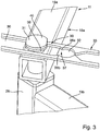
- Figur 3
- eine perspektivische Darstellung im vergrößerten Maßstab der Arretiervorrichtung von
Figur 1 . - Die
Figuren 1 bis 3 zeigen ein bevorzugtes Ausführungsbeispiel der erfindungsgemäßen Führungsvorrichtung 11 beim Einsatz an einer Erhitzungsvorrichtung in Form eines Backofens. Es wäre auch denkbar, die Führungsvorrichtung 11 in anderen Erhitzungsvorrichtungen einzusetzen, beispielsweise in einen Dampfgarer oder einer Mikrowelle. - Im Folgenden wird die erfindungsgemäße Führungsvorrichtung jedoch am Beispielsfall Backofen erläutert. Der Backofen besitzt ein Gehäuse (nicht dargestellt), das beispielweise quaderförmig ausgebildet sein kann.
- Das Gehäuse umschließt einen aufheizbaren Innenraum (nicht dargestellt), der rückseitig von einer Rückwand (nicht dargestellt) und vorderseitig von einer Tür (nicht dargestellt) begrenzt ist.
- Die Tür verschließt in einer Schließstellung einen Zugang zu dem Innenraum. Zweckmäßigerweise ist die Tür als Klappe ausgebildet und lässt sich beim Öffnen nach vorne unten wegklappen.
- Ferner besitzt das Gehäuse zwei einander gegenüberliegende Seitenwände (nicht dargestellt), einen Boden (nicht dargestellt) und einen diesem gegenüberliegende Oberwand (nicht dargestellt).
- Im Gehäuse ist wenigstens ein nach dem Öffnen der Tür aus dem Gehäuse entnehmbarer Gutträger 12 zur Erhitzung von Gut aufgenommen. Im Beispielsfall Backofen ist der Gutträger als Gargutträger ausgebildet, beispielsweise in Form eines Backblechs oder Gitterrosts.
- Wie insbesondere in den
Figuren 1 und2 gezeigt, besitzt die Führungsvorrichtung 11 zwei Führungseinheiten 13a, 13b, die jeweils mit Querabstand zueinander einerseits über Befestigungsmittel 14 am Gehäuse befestigt und andererseits an den Gutträger 12 angekoppelt sind und die den Gutträger 12 durch eine Verfahrbewegung zwischen einer eingeschobenen Betriebsposition 15 (Figur 1 ) und einer zumindest teilweise aus dem Gehäuse herausgezogenen Ausziehposition 16 (Figur 2 ) führen. Die Befestigungsmittel 14 umfassen eine beispielsweise aus Stahlmaterial gefertigte Befestigungskonsole 17, an der einerseits in nachfolgend noch beschriebener Weise die Führungseinheiten schwenkbar gelagert sind und die andererseits am Gehäuse, insbesondere an der Rückwand, befestigt ist. - Wie insbesondere in
Figur 1 gezeigt, weisen die Führungseinheiten 13a, 13b jeweils eine aus mehreren Führungsarmen bestehendes Führungsgestänge 18a, 18b auf, das nach Art einer Ziehharmonika beweglich ist und dabei den Gutträger zwischen der Betriebsposition 15 und der Ausziehposition 16 führt. - Im gezeigten Beispielsfall sind zwei Führungseinheiten 13a, 13b vorgesehen, die jeweils aus Führungsarmen bestehen und jeweils ein Führungsgestänge 18a, 18b aufweisen, wobei die Führungsgestänge gemeinsam eine Art Ziehharmonika-Führung bilden.
- Wie insbesondere in
Figur 1 gezeigt, weisen die Führungsgestänge 18a, 18b jeweils zwei Schwenkarme 19a, 19b; 20a, 20b auf, von denen ein erster Schwenkarm 19a, 20a um eine gehäuseseitige erste Schwenkachse 21 und ein zweiter Schwenkarm 19b, 20b um eine gutträgerseitige Schwenkachse 22 (Figur 2 ) schwenkbar gelagert ist. Im gezeigten Beispielsfall befinden sich die gehäuseseitige Schwenkachsen 21 der beiden Führungsgestänge 18a, 18b an der Befestigungskonsole 17, insbesondere an einem dort waagrecht ausgerichteten Befestigungsschenkel 23 der Befestigungskonsole 17. Die beiden Schwenkachsen 19a, 19b; 20a, 20b eines jeweiligen Führungsgestänges 18a, 18b sind über eine dritte Schwenkachse 24, die auch als Verbindungsgelenke bezeichnet werden können, schwenkbar miteinander verbunden. Dadurch bilden die beiden Schwenkarme 19a, 19b; 20a, 20b jeweils einen Kniehebel. - Wie insbesondere in
Figur 1 gezeigt, besitzt jedes Führungsgestänge 18a, 18b ein oberes Schwenkarm-Paar und ein unteres Schwenkarm-Paar. Die Schwenkarm-Paare bestehen jeweils aus einem ersten und einem zweiten Schwenkarm 19a, 19b; 20a, 20b. Die beiden Schwenkarm-Paare eines jeweiligen Führungsgestänges 18a, 18b sind durch drei Vertikalstreben 25, 26, 27 miteinander verbunden. Die erste Vertikalstrebe 25 befindet sich im Bereich der gehäuseseitigen ersten Schwenkachse 21 und bildet somit einen Schwenkachskörper. Die zweite Vertikalstrebe 26 befindet sich im Bereich des Verbindungsgelenks beziehungsweise der dritten Schwenkachse 24 und die dritte Vertikalstrebe 27 im Bereich der gutträgerseitigen zweiten Schwenkachse und bildet dort einen Schwenkachskörper. Durch die beiden Schwenkarm-Paare und die Vertikalstreben bildet ein jeweiliges Führungsgestänge 18a, 18b eine Art Türflügel (ohne Türblatt) nach Art einer Falttür. Wie insbesondere inFigur 1 gezeigt, sind die Führungseinheiten 13a, 13b insbesondere die Führungsgestänge 18a, 18b mittels einer zur Führungsvorrichtung 11 gehörenden Kopplungseinrichtung 28 mit dem Gutträger 12 gekoppelt. Die Kopplungseinrichtung 28 weist eine Schottwand 29 auf, die auch als doppelte Rückwand bezeichnet werden könnte. Die Schottwand 29 ist mittels der Führungseinheiten 13a, 13b zwischen einer im Bereich der Rückwand des Gehäuses befindlichen Betriebsposition und einer im Bereich der Gehäuseöffnung hinausgezogene Verschlussposition beweglich gelagert. Wie insbesondere inFigur 2 gezeigt, befinden sich die gutträgerseitigen zweiten Schwenkachsen 22 im Bereich der Schottwand 29. - Die Führungsvorrichtung 11 umfasst ferner eine den Führungseinheiten 13a, 13b zugeordnete Arretiervorrichtung 30, die zur lösbaren Arretierung des Gutträgers 12 in der herausgezogenen Ausziehposition 16 ausgebildet ist.
- Die Arretiervorrichtung 30 ist derart ausgebildet, dass sie beim Erreichen der Ausziehposition 16 des Gutträgers 12 selbsttätig oder mit Hilfe von Auszugsmitteln in einen arretierenden Betriebszustand gelangt.
- Die Arretiervorrichtung 30 weist ein erstes Arretierelement in Form eines Arretiervorsprungs 31 und ein zweites Arretierelement in Form einer Arretierkerbe 32 auf. Arretiervorsprung und Arretierkerbe 31, 32 stehen in der herausgezogenen Ausziehposition in Eingriff miteinander während sie außerhalb der Ausziehposition 16 außer Eingriff miteinander stehen.
- Eines der Arretierelemente, im gezeigten Beispielsfall die Arretierkerbe 32 ist an einem von den Führungseinheiten 13a, 13b separaten Arretierbauteil 33 angeordnet, das bei der Verfahrbewegung der Führungseinheiten 13a, 13b derart mitbewegbar ist, dass das daran angeordnete Arretierelement beim Einfahren in die herausgezogene Ausziehposition 16 in Eingriff mit dem anderen Arretierelement, also den Arretiervorsprung 31 gelangt.
- Im gezeigten Beispielsfall ist das Arretier-Bauteil 33 als Arretierstange ausgebildet, die einenends um eine Stangen-Schwenkachse 34 gutträgerseitig, also insbesondere an der Schottwand 29 schwenkbar gelagert ist und andernends mit dem Arretierelement in Form der Arretierkerbe ausgestattet ist. Im gezeigten Beispielsfall befindet sich also die Arretierkerbe 32 an der Arretierstange, während sich der Arretiervorsprung 31 an einem der Führungsgestänge 18a befindet.
- Wie insbesondere die
Figuren 1 und3 zeigen, ist die Arretierstange ein flaches, länglich gestrecktes Bauteil. Die Arretierstange besitzt einen in deren Längsrichtung 35 ausgerichteten Längsschlitz 36, der von dem Arretiervorsprung 31 durchsetzt ist und der entlang des Arretiervorsprungs 31 bei der sich überlagernden Schwenkbewegung von Arretierstange einerseits und Führungsgestänge 18a andererseits geführt ist. - Wie insbesondere in
Figur 3 gezeigt, erstreckt sich der Längsschlitz 36 vom freien Ende der Arretierstange in Richtung des mit der Stangen-Schwenkachse 34 ausgestatteten hinteren Endes der Arretierstange. Der Längsschlitz 36 erstreckt sich zweckmäßigerweise nicht über die gesamte Länge der Arretierstange sondern beispielsweise nur über einem Drittel, insbesondere einem Viertel der Länge der Arretierstange. Die Arretierkerbe 32 ist in den Verlauf des Längsschlitzes 36 eingeschaltet. - Wie insbesondere in
Figur 3 gezeigt, weist der Längsschlitz 36 eine Engstelle 37 auf, die durch zwei einander gegenüberliegende, jeweils ins Innere des Längsschlitzes 36 hineinragende Arretiervorsprünge 38a, 38b gebildet ist. In Längsrichtung anschließend an die Engstelle in Richtung zum hinteren Stangenende hin erstreckt sich die Arretierkerbe 32, die auch als Rastaufnahme oder Rastöffnung bezeichnet werden könnte. - Wie bereits erwähnt, befindet sich der Arretiervorsprung 31 im gezeigten Beispielsfall an einem der Führungsgestänge 18a. Zweckmäßigerweise ist der Arretiervorsprung 31 eine Verlängerung des Verbindungsgelenks zwischen den Schwenkarmen 19a, 19b des oberen Schwenkarm-Paares. Die Schwenkarme 19a, 19b; 20a, 20b können jeweils als Rohre, beispielsweise Vierkantrohre, ausgebildet sein. Der Arretiervorsprung 31 steht von einem der Schwenkarme, insbesondere vom gehäuseseitigen hinteren Schwenkarm 19a nach oben ab. Der Arretiervorsprung 31 ist im gezeigten Beispielsfall als eine Art Knopf ausgebildet, der einen Halsabschnitt 39 aufweist, der den Längsschlitz 36 an der Arretierstange durchsetzt, sodass der Längsschlitz 36 sich relativ zum Arretiervorsprung 31 bewegen kann. Zum freien Ende hin schließt an den Halsabschnitt 39 des Arretiervorsprungs 31 ein Kopfabschnitt 40 an, dessen Querschnitt größer als der Querschnitt des Längsschlitzes 36 ist und dafür sorgt, dass die Arretierstange in Höhenrichtung nicht vom Arretiervorsprung 31 ausgehebelt werden kann.
- Um Zugriff auf das auf den Gargutträger befindliche Gargut zu erhalten, wird die Tür des Backofens insbesondere die Klappe geöffnet. Danach wird mittels Handhabung am Gargutträger selber dieser aus der Gehäuseöffnung des Gehäuses des Backofens herausgezogen, wobei das Führungsgestänge dafür sorgt, dass die Schottwand samt dem Gutträger nach vorne hin verlagert wird. Der Gutträger wird also von der eingeschobenen Betriebsposition 15 mittels der Führungseinheiten 13a, 13b in die herausgezogene Ausziehposition 16 verfahren. Dabei werden Arretierstange und zugeordnetes Führungsgestänge 18a relativ zueinander verschwenkt. Wie in
Figur 1 gezeigt, befindet sich der Arretiervorsprung 31 zunächst am vorderen Ende des Längsschlitzes. Beim Herausziehen des Gargutträgers wird der Arretiervorsprung 31 in Richtung der Engstelle 37 verlagert und rastet dann in der vorgesehenen Ausziehposition selbstständig über die beiden Arretiervorsprünge 38 in die Arretierkerbe 32 ein. Eine ungewollte Rückbewegung in Richtung der Betriebsposition, beispielsweise durch Handhabung am Gargut des Gargutträgers wird durch die beiden Arretiervorsprünge verhindert. Die Rückbewegung erfordert eine durch den Benutzer aufzubringende definierte Kraft, sodass der Halsabschnitt 39 des Arretiervorsprungs wieder über die Arretiervorsprünge 38 zurückschnappt, sodass eine Weiterbewegung beziehungsweise Einfahrbewegung in die Betriebsposition 15 möglich ist.
Claims (15)
- Führungsvorrichtung zur Führung eines Gutträgers (12) in einem Gehäuse, mit wenigstens zwei Führungseinheiten (13a, 13b), die jeweils mit Querabstand zueinander einerseits am Gehäuse befestigbar und andererseits an den Gutträger (12) koppelbar sind und die den Gutträger durch eine Verfahrbewegung zwischen einer eingeschobenen Betriebsposition (15) und einer mindestens teilweise aus dem Gehäuse herausgezogenen Ausziehposition (16) führen, gekennzeichnet durch eine den Führungseinheiten (13a, 13b) zugeordnete Arretiervorrichtung (30), die zur lösbaren Arretierung des Gutträgers (12) in der herausgezogenen Ausziehposition (16) ausgebildet ist.
- Führungsvorrichtung nach Anspruch 1, dadurch gekennzeichnet, dass die Arretiervorrichtung (30) derart ausgebildet ist, dass sie beim Erreichen der Ausziehposition (16) des Gutträgers (12) in einen arretierenden Betriebszustand gelangt.
- Führungsvorrichtung nach Anspruch 1 oder 2, dadurch gekennzeichnet, dass die Arretiervorrichtung (30) ein erstes Arretierelement und ein zweites Arretierelement aufweist, die in der herausgezogenen Ausziehposition (16) in Eingriff miteinander stehen und außerhalb der Ausziehposition (16) außer Eingriff miteinander stehen.
- Führungsvorrichtung nach Anspruch 3, dadurch gekennzeichnet, dass das erste Arretierelement als Arretiervorsprung (31) und das zweite Arretierelement als Arretierkerbe (32) ausgebildet ist, oder umgekehrt.
- Führungsvorrichtung nach Anspruch 3 oder 4, dadurch gekennzeichnet, dass eines der Arretierelemente an einem von der Führungseinheit (13a, 13b) separaten Arretier-Bauteil (33) angeordnet ist, das bei der Verfahrbewegung der Führungseinheit (13a, 13b) derart mitbewegbar ist, dass das daran angeordnete Arretierelement beim Einfahren in die herausgezogene Ausziehposition (16) in Eingriff mit dem anderen Arretierelement gelangt.
- Führungsvorrichtung nach Anspruch 5, dadurch gekennzeichnet, dass der Arretiervorsprung an der Führungseinheit (13a, 13b) und die Arretierkerbe (32) am separaten Arretier-Bauteil (33) ausgebildet ist.
- Führungsvorrichtung nach einem der vorhergehenden Ansprüche, dadurch gekennzeichnet, dass die Führungseinheiten (13a, 13b) jeweils ein aus mehreren Führungsarmen bestehendes Führungsgestänge (18a, 18b) aufweisen, das nach Art einer Ziehharmonika beweglich ist und dabei den Gutträger (12) zwischen der Betriebs- und der Ausziehposition (15, 16) führt, wobei vorzugsweise die Führungsarme als schwenkbar miteinander verbundene, um korpusseitige und/oder gutträgerseitige Schwenkachsen (21, 22) schwenkbare Schwenkarme (19a, 19b; 20a, 20b) ausgebildet sind.
- Führungsvorrichtung nach Anspruch 7, dadurch gekennzeichnet, dass die Führungsgestänge (18a, 18b) jeweils zwei Schwenkarme (19a, 19b; 20a, 20b) aufweisen, von denen ein erster Schwenkarm (19a, 20a) um eine gehäuseseitige erste Schwenkachse (21) und ein zweiter Schwenkarm (19b, 20b) um eine gutträgerseitige zweite Schwenkachse (22) schwenkbar gelagert ist und wobei die beiden Schwenkarme (19a, 20a; 19b, 20b) über ein Verbindungsgelenk (24) schwenkbar miteinander verbunden sind.
- Führungsvorrichtung nach einem der vorhergehenden Ansprüche, dadurch gekennzeichnet, dass die Führungseinheiten (13a, 13b) mittels einer zur Führungsvorrichtung gehörenden Kopplungseinrichtung (28) mit dem Gutträger (12) gekoppelt sind.
- Führungseinrichtung nach Anspruch 9, dadurch gekennzeichnet, dass die Kopplungseinrichtung (28) eine Schottwand (29) aufweist, die mittels der Führungseinheiten (13a, 13b) zwischen einer im Bereich der Rückwand befindlichen Betriebsposition (15) und einer in den Bereich der Gehäuseöffnung herausgezogenen Verschlussposition beweglich gelagert ist.
- Führungsvorrichtung nach einem der Ansprüche 5 bis 10, dadurch gekennzeichnet, dass das Arretier-Bauteil (33) als Arretierstange ausgebildet ist, die einerseits um eine Stangen-Schwenkachse (34) schwenkbar gelagert ist und andernends mit dem Arretierelement, insbesondere der Arretierkerbe (32) ausgestattet ist, wobei das andere Arretierelement, insbesondere der Arretiervorsprung (31), an einem der Führungsgestänge (18a) ausgebildet ist und durch die Arretierstange und das zugeordnete Führungsgestänge (18a) bei der Verfahrbewegung eine sich überlagernde Schwenkbewegung ausführbar ist, die beim Einfahren in die herausgezogene Ausziehposition (16) ein Einrasten des Arretiervorsprungs (31) in die Arretierkerbe (32) bewirkt.
- Führungsvorrichtung nach Anspruch 11, dadurch gekennzeichnet, dass die Stangen-Schwenkachse (34) an der Schottwand (29) sitzt.
- Führungsvorrichtung nach Anspruch 11 oder 12, dadurch gekennzeichnet, dass die Arretierstange einen in deren Längsrichtung (35) ausgerichteten Längsschlitz (36) aufweist, der von dem Arretiervorsprung (31) durchsetzt ist und der entlang des Arretiervorsprungs (31) bei der sich überlagernden Schwenkbewegung von Arretierstange und Führungsgestänge (18a) geführt ist, wobei ein der Stangen-Schwenkachse (34) zugeordnetes hinteres Ende des Längsschlitzes (36) mit der Arretierkerbe (31) ausgestattet ist.
- Führungsvorrichtung nach einem der Ansprüche 4 bis 13, dadurch gekennzeichnet, dass der Arretiervorsprung (31) als Verlängerung des Verbindungsgelenks ausgebildet ist und von einer Oberseite des Führungsgestänges (18a) nach oben absteht.
- Erhitzungsvorrichtung, insbesondere Ofen, mit einem einen aufheizbaren Innenraum umschließenden Gehäuse, wobei der Innenraum rückseitig von einer Rückwand und vorderseitig von einer Tür begrenzt ist, die in einer Schließstellung einen Zugang zu dem Innenraum gestattenden Gehäuseöffnung verschließt, wobei im Gehäuse wenigstens ein nach dem Öffnen der Tür aus dem Gehäuse entnehmbarer Gutträger (12) für zu erhitzendes Gut aufgenommen ist, gekennzeichnet durch eine Führungsvorrichtung (11) nach einem der Ansprüche 1 bis 14.
Priority Applications (1)
| Application Number | Priority Date | Filing Date | Title |
|---|---|---|---|
| SI201930321T SI3653938T1 (sl) | 2018-11-12 | 2019-10-08 | Vodilna naprava za vodenje police v ohišju |
Applications Claiming Priority (1)
| Application Number | Priority Date | Filing Date | Title |
|---|---|---|---|
| DE202018106399.5U DE202018106399U1 (de) | 2018-11-12 | 2018-11-12 | Führungsvorrichtung zur Führung eines Gutträgers in einem Gehäuse |
Publications (2)
| Publication Number | Publication Date |
|---|---|
| EP3653938A1 true EP3653938A1 (de) | 2020-05-20 |
| EP3653938B1 EP3653938B1 (de) | 2022-08-17 |
Family
ID=68242277
Family Applications (1)
| Application Number | Title | Priority Date | Filing Date |
|---|---|---|---|
| EP19201849.7A Active EP3653938B1 (de) | 2018-11-12 | 2019-10-08 | Führungsvorrichtung zur führung eines gutträgers in einem gehäuse |
Country Status (5)
| Country | Link |
|---|---|
| EP (1) | EP3653938B1 (de) |
| DE (1) | DE202018106399U1 (de) |
| ES (1) | ES2925962T3 (de) |
| PL (1) | PL3653938T3 (de) |
| SI (1) | SI3653938T1 (de) |
Citations (8)
| Publication number | Priority date | Publication date | Assignee | Title |
|---|---|---|---|---|
| US2133639A (en) * | 1936-07-24 | 1938-10-18 | Walker & Pratt Mfg Co | Range |
| DE10243551A1 (de) * | 2002-09-19 | 2004-04-01 | BSH Bosch und Siemens Hausgeräte GmbH | Gargerät |
| DE102004032250A1 (de) * | 2004-07-03 | 2006-02-16 | Bayerische Motoren Werke Ag | Lacktürhalter |
| NZ543764A (en) * | 2005-11-24 | 2008-10-31 | Fisher & Paykel Appliances Ltd | Oven with vertically moveable shelf in drawer |
| EP2645003A1 (de) * | 2012-03-30 | 2013-10-02 | BSH Bosch und Siemens Hausgeräte GmbH | Gargutträger für ein Gargerät |
| DE202014104795U1 (de) * | 2014-10-07 | 2016-01-11 | Grass Gmbh | Vorrichtung zur Bewegungsführung eines Schubelements, Schubelement und Möbel |
| EP3081864A1 (de) * | 2015-04-14 | 2016-10-19 | BSH Hausgeräte GmbH | Auszugssystem für ein haushaltsgerät |
| DE202017100609U1 (de) * | 2017-02-06 | 2018-05-16 | Grass Gmbh | Vorrichtung zur Anbringung eines Trägerelements für Gegenstände in einem Korpus |
Family Cites Families (7)
| Publication number | Priority date | Publication date | Assignee | Title |
|---|---|---|---|---|
| DE578161C (de) * | 1930-09-12 | 1933-06-10 | Ernest Lodge Wilson | Backofen, Herd u. dgl. |
| DE4023949A1 (de) * | 1990-02-21 | 1991-08-22 | Bosch Siemens Hausgeraete | Backofen |
| DE10203957A1 (de) * | 2002-02-01 | 2003-08-14 | Bsh Bosch Siemens Hausgeraete | Haushaltsgerät, insbesondere Backofen |
| DE10211519A1 (de) * | 2002-03-15 | 2003-09-25 | Bsh Bosch Siemens Hausgeraete | Backofen und Backwagen |
| DE10221181A1 (de) * | 2002-05-13 | 2003-11-27 | Appbau Gmbh Laag | Backwagenauswerfer |
| DE102005036990A1 (de) * | 2005-08-05 | 2007-02-08 | BSH Bosch und Siemens Hausgeräte GmbH | Hausgeräteauszugsvorrichtung |
| DE202012104877U1 (de) * | 2012-12-14 | 2013-01-31 | Hans Giesbert Gmbh & Co. Kg | Teleskopierbarer Schienenauszug für einen schubladenartigen Geräte- oder Möbelkorpus |
-
2018
- 2018-11-12 DE DE202018106399.5U patent/DE202018106399U1/de not_active Expired - Lifetime
-
2019
- 2019-10-08 ES ES19201849T patent/ES2925962T3/es active Active
- 2019-10-08 SI SI201930321T patent/SI3653938T1/sl unknown
- 2019-10-08 PL PL19201849.7T patent/PL3653938T3/pl unknown
- 2019-10-08 EP EP19201849.7A patent/EP3653938B1/de active Active
Patent Citations (8)
| Publication number | Priority date | Publication date | Assignee | Title |
|---|---|---|---|---|
| US2133639A (en) * | 1936-07-24 | 1938-10-18 | Walker & Pratt Mfg Co | Range |
| DE10243551A1 (de) * | 2002-09-19 | 2004-04-01 | BSH Bosch und Siemens Hausgeräte GmbH | Gargerät |
| DE102004032250A1 (de) * | 2004-07-03 | 2006-02-16 | Bayerische Motoren Werke Ag | Lacktürhalter |
| NZ543764A (en) * | 2005-11-24 | 2008-10-31 | Fisher & Paykel Appliances Ltd | Oven with vertically moveable shelf in drawer |
| EP2645003A1 (de) * | 2012-03-30 | 2013-10-02 | BSH Bosch und Siemens Hausgeräte GmbH | Gargutträger für ein Gargerät |
| DE202014104795U1 (de) * | 2014-10-07 | 2016-01-11 | Grass Gmbh | Vorrichtung zur Bewegungsführung eines Schubelements, Schubelement und Möbel |
| EP3081864A1 (de) * | 2015-04-14 | 2016-10-19 | BSH Hausgeräte GmbH | Auszugssystem für ein haushaltsgerät |
| DE202017100609U1 (de) * | 2017-02-06 | 2018-05-16 | Grass Gmbh | Vorrichtung zur Anbringung eines Trägerelements für Gegenstände in einem Korpus |
Also Published As
| Publication number | Publication date |
|---|---|
| PL3653938T3 (pl) | 2023-05-08 |
| DE202018106399U1 (de) | 2020-02-13 |
| SI3653938T1 (sl) | 2022-10-28 |
| ES2925962T3 (es) | 2022-10-20 |
| EP3653938B1 (de) | 2022-08-17 |
Similar Documents
| Publication | Publication Date | Title |
|---|---|---|
| EP2760315B1 (de) | Beschlag | |
| EP2713816B1 (de) | Beschlag für eckschränke | |
| EP0450457B1 (de) | Brotröster mit einer Nachhebevorrichtung für den Röstgutträger | |
| DE102010007129A1 (de) | Beschlag für Eckschränke | |
| EP3315047B1 (de) | Steuervorrichtung zur bewegungssteuerung einer eckschranktür eines eckschranks | |
| DE4330867C1 (de) | Ausziehbares Einbaubügelbrett | |
| DE102014018104B4 (de) | Liftbeschlag für Einrichtungsgegenstände von Möbeln | |
| EP2402237B1 (de) | Befestigungseinrichtung für ein abnehmbar an einem Motorrad fixierten bzw. fixierbaren Gepäckbehälter | |
| EP3358258B1 (de) | Möbel | |
| WO2019219408A1 (de) | Verfahren zum schwenkbaren befestigen eines möbeldeckels an einen möbelkorpus mittels eines deckelbeschlags und möbel mit deckelbeschlag | |
| EP3653938B1 (de) | Führungsvorrichtung zur führung eines gutträgers in einem gehäuse | |
| EP3599425B1 (de) | Führungsvorrichtung mit halterungen zum befestigung an einer tragstabanordnung | |
| EP0011297B1 (de) | Behälter mit einem Klappschiebedeckel für den vorderen und einem weiteren Deckel für den hinteren Teil der Behälteröffnung, insbesondere Müllbehälter | |
| DE10105847B4 (de) | Mitnahmevorrichtung für ausziehbaren Möbelboden | |
| EP3499132B1 (de) | Erhitzungsvorrichtung, insbesondere ofen | |
| DE3101628C2 (de) | Schreibtisch | |
| EP1169963A1 (de) | Blende für Möbel | |
| DE915781C (de) | Halterung fuer einen Gepaeckraumdeckel an Kraftfahrzeugen | |
| EP2444285B1 (de) | Höhenverstellbarer Ladeboden | |
| EP2413741B1 (de) | Einzugvorrichtung | |
| EP0566982A1 (de) | Gleiterbahn für eine Verbindung zweier Elemente | |
| EP3499130B1 (de) | Erhitzungsvorrichtung, insbesondere ofen, mit einem gutträger | |
| DE3233991C2 (de) | Ausziehtisch mit dreigeteilter Tischplatte | |
| EP3338613A1 (de) | Haushaltsgeschirrspülmaschine | |
| EP3729999B1 (de) | Eckschrank mit einem inneren tablar und einer mitnehmervorrichtung für die tür |
Legal Events
| Date | Code | Title | Description |
|---|---|---|---|
| PUAI | Public reference made under article 153(3) epc to a published international application that has entered the european phase |
Free format text: ORIGINAL CODE: 0009012 |
|
| STAA | Information on the status of an ep patent application or granted ep patent |
Free format text: STATUS: THE APPLICATION HAS BEEN PUBLISHED |
|
| AK | Designated contracting states |
Kind code of ref document: A1 Designated state(s): AL AT BE BG CH CY CZ DE DK EE ES FI FR GB GR HR HU IE IS IT LI LT LU LV MC MK MT NL NO PL PT RO RS SE SI SK SM TR |
|
| AX | Request for extension of the european patent |
Extension state: BA ME |
|
| STAA | Information on the status of an ep patent application or granted ep patent |
Free format text: STATUS: REQUEST FOR EXAMINATION WAS MADE |
|
| 17P | Request for examination filed |
Effective date: 20201119 |
|
| RBV | Designated contracting states (corrected) |
Designated state(s): AL AT BE BG CH CY CZ DE DK EE ES FI FR GB GR HR HU IE IS IT LI LT LU LV MC MK MT NL NO PL PT RO RS SE SI SK SM TR |
|
| STAA | Information on the status of an ep patent application or granted ep patent |
Free format text: STATUS: EXAMINATION IS IN PROGRESS |
|
| 17Q | First examination report despatched |
Effective date: 20210318 |
|
| GRAP | Despatch of communication of intention to grant a patent |
Free format text: ORIGINAL CODE: EPIDOSNIGR1 |
|
| STAA | Information on the status of an ep patent application or granted ep patent |
Free format text: STATUS: GRANT OF PATENT IS INTENDED |
|
| INTG | Intention to grant announced |
Effective date: 20220317 |
|
| GRAS | Grant fee paid |
Free format text: ORIGINAL CODE: EPIDOSNIGR3 |
|
| GRAA | (expected) grant |
Free format text: ORIGINAL CODE: 0009210 |
|
| STAA | Information on the status of an ep patent application or granted ep patent |
Free format text: STATUS: THE PATENT HAS BEEN GRANTED |
|
| AK | Designated contracting states |
Kind code of ref document: B1 Designated state(s): AL AT BE BG CH CY CZ DE DK EE ES FI FR GB GR HR HU IE IS IT LI LT LU LV MC MK MT NL NO PL PT RO RS SE SI SK SM TR |
|
| REG | Reference to a national code |
Ref country code: CH Ref legal event code: EP |
|
| REG | Reference to a national code |
Ref country code: DE Ref legal event code: R096 Ref document number: 502019005316 Country of ref document: DE |
|
| REG | Reference to a national code |
Ref country code: IE Ref legal event code: FG4D Free format text: LANGUAGE OF EP DOCUMENT: GERMAN |
|
| REG | Reference to a national code |
Ref country code: AT Ref legal event code: REF Ref document number: 1512416 Country of ref document: AT Kind code of ref document: T Effective date: 20220915 |
|
| REG | Reference to a national code |
Ref country code: ES Ref legal event code: FG2A Ref document number: 2925962 Country of ref document: ES Kind code of ref document: T3 Effective date: 20221020 |
|
| REG | Reference to a national code |
Ref country code: NL Ref legal event code: MP Effective date: 20220817 |
|
| REG | Reference to a national code |
Ref country code: LT Ref legal event code: MG9D |
|
| PG25 | Lapsed in a contracting state [announced via postgrant information from national office to epo] |
Ref country code: SE Free format text: LAPSE BECAUSE OF FAILURE TO SUBMIT A TRANSLATION OF THE DESCRIPTION OR TO PAY THE FEE WITHIN THE PRESCRIBED TIME-LIMIT Effective date: 20220817 Ref country code: RS Free format text: LAPSE BECAUSE OF FAILURE TO SUBMIT A TRANSLATION OF THE DESCRIPTION OR TO PAY THE FEE WITHIN THE PRESCRIBED TIME-LIMIT Effective date: 20220817 Ref country code: PT Free format text: LAPSE BECAUSE OF FAILURE TO SUBMIT A TRANSLATION OF THE DESCRIPTION OR TO PAY THE FEE WITHIN THE PRESCRIBED TIME-LIMIT Effective date: 20221219 Ref country code: NO Free format text: LAPSE BECAUSE OF FAILURE TO SUBMIT A TRANSLATION OF THE DESCRIPTION OR TO PAY THE FEE WITHIN THE PRESCRIBED TIME-LIMIT Effective date: 20221117 Ref country code: NL Free format text: LAPSE BECAUSE OF FAILURE TO SUBMIT A TRANSLATION OF THE DESCRIPTION OR TO PAY THE FEE WITHIN THE PRESCRIBED TIME-LIMIT Effective date: 20220817 Ref country code: LV Free format text: LAPSE BECAUSE OF FAILURE TO SUBMIT A TRANSLATION OF THE DESCRIPTION OR TO PAY THE FEE WITHIN THE PRESCRIBED TIME-LIMIT Effective date: 20220817 Ref country code: LT Free format text: LAPSE BECAUSE OF FAILURE TO SUBMIT A TRANSLATION OF THE DESCRIPTION OR TO PAY THE FEE WITHIN THE PRESCRIBED TIME-LIMIT Effective date: 20220817 Ref country code: FI Free format text: LAPSE BECAUSE OF FAILURE TO SUBMIT A TRANSLATION OF THE DESCRIPTION OR TO PAY THE FEE WITHIN THE PRESCRIBED TIME-LIMIT Effective date: 20220817 |
|
| PG25 | Lapsed in a contracting state [announced via postgrant information from national office to epo] |
Ref country code: IS Free format text: LAPSE BECAUSE OF FAILURE TO SUBMIT A TRANSLATION OF THE DESCRIPTION OR TO PAY THE FEE WITHIN THE PRESCRIBED TIME-LIMIT Effective date: 20221217 Ref country code: HR Free format text: LAPSE BECAUSE OF FAILURE TO SUBMIT A TRANSLATION OF THE DESCRIPTION OR TO PAY THE FEE WITHIN THE PRESCRIBED TIME-LIMIT Effective date: 20220817 Ref country code: GR Free format text: LAPSE BECAUSE OF FAILURE TO SUBMIT A TRANSLATION OF THE DESCRIPTION OR TO PAY THE FEE WITHIN THE PRESCRIBED TIME-LIMIT Effective date: 20221118 |
|
| PG25 | Lapsed in a contracting state [announced via postgrant information from national office to epo] |
Ref country code: SM Free format text: LAPSE BECAUSE OF FAILURE TO SUBMIT A TRANSLATION OF THE DESCRIPTION OR TO PAY THE FEE WITHIN THE PRESCRIBED TIME-LIMIT Effective date: 20220817 Ref country code: RO Free format text: LAPSE BECAUSE OF FAILURE TO SUBMIT A TRANSLATION OF THE DESCRIPTION OR TO PAY THE FEE WITHIN THE PRESCRIBED TIME-LIMIT Effective date: 20220817 Ref country code: DK Free format text: LAPSE BECAUSE OF FAILURE TO SUBMIT A TRANSLATION OF THE DESCRIPTION OR TO PAY THE FEE WITHIN THE PRESCRIBED TIME-LIMIT Effective date: 20220817 Ref country code: CZ Free format text: LAPSE BECAUSE OF FAILURE TO SUBMIT A TRANSLATION OF THE DESCRIPTION OR TO PAY THE FEE WITHIN THE PRESCRIBED TIME-LIMIT Effective date: 20220817 |
|
| REG | Reference to a national code |
Ref country code: DE Ref legal event code: R097 Ref document number: 502019005316 Country of ref document: DE |
|
| PG25 | Lapsed in a contracting state [announced via postgrant information from national office to epo] |
Ref country code: SK Free format text: LAPSE BECAUSE OF FAILURE TO SUBMIT A TRANSLATION OF THE DESCRIPTION OR TO PAY THE FEE WITHIN THE PRESCRIBED TIME-LIMIT Effective date: 20220817 Ref country code: MC Free format text: LAPSE BECAUSE OF FAILURE TO SUBMIT A TRANSLATION OF THE DESCRIPTION OR TO PAY THE FEE WITHIN THE PRESCRIBED TIME-LIMIT Effective date: 20220817 Ref country code: EE Free format text: LAPSE BECAUSE OF FAILURE TO SUBMIT A TRANSLATION OF THE DESCRIPTION OR TO PAY THE FEE WITHIN THE PRESCRIBED TIME-LIMIT Effective date: 20220817 |
|
| REG | Reference to a national code |
Ref country code: CH Ref legal event code: PL |
|
| PLBE | No opposition filed within time limit |
Free format text: ORIGINAL CODE: 0009261 |
|
| STAA | Information on the status of an ep patent application or granted ep patent |
Free format text: STATUS: NO OPPOSITION FILED WITHIN TIME LIMIT |
|
| REG | Reference to a national code |
Ref country code: BE Ref legal event code: MM Effective date: 20221031 |
|
| P01 | Opt-out of the competence of the unified patent court (upc) registered |
Effective date: 20230519 |
|
| PG25 | Lapsed in a contracting state [announced via postgrant information from national office to epo] |
Ref country code: LU Free format text: LAPSE BECAUSE OF NON-PAYMENT OF DUE FEES Effective date: 20221008 Ref country code: AL Free format text: LAPSE BECAUSE OF FAILURE TO SUBMIT A TRANSLATION OF THE DESCRIPTION OR TO PAY THE FEE WITHIN THE PRESCRIBED TIME-LIMIT Effective date: 20220817 |
|
| 26N | No opposition filed |
Effective date: 20230519 |
|
| PG25 | Lapsed in a contracting state [announced via postgrant information from national office to epo] |
Ref country code: LI Free format text: LAPSE BECAUSE OF NON-PAYMENT OF DUE FEES Effective date: 20221031 Ref country code: CH Free format text: LAPSE BECAUSE OF NON-PAYMENT OF DUE FEES Effective date: 20221031 |
|
| PG25 | Lapsed in a contracting state [announced via postgrant information from national office to epo] |
Ref country code: BE Free format text: LAPSE BECAUSE OF NON-PAYMENT OF DUE FEES Effective date: 20221031 |
|
| PG25 | Lapsed in a contracting state [announced via postgrant information from national office to epo] |
Ref country code: IE Free format text: LAPSE BECAUSE OF NON-PAYMENT OF DUE FEES Effective date: 20221008 |
|
| PG25 | Lapsed in a contracting state [announced via postgrant information from national office to epo] |
Ref country code: HU Free format text: LAPSE BECAUSE OF FAILURE TO SUBMIT A TRANSLATION OF THE DESCRIPTION OR TO PAY THE FEE WITHIN THE PRESCRIBED TIME-LIMIT; INVALID AB INITIO Effective date: 20191008 |
|
| PG25 | Lapsed in a contracting state [announced via postgrant information from national office to epo] |
Ref country code: CY Free format text: LAPSE BECAUSE OF FAILURE TO SUBMIT A TRANSLATION OF THE DESCRIPTION OR TO PAY THE FEE WITHIN THE PRESCRIBED TIME-LIMIT Effective date: 20220817 |
|
| PG25 | Lapsed in a contracting state [announced via postgrant information from national office to epo] |
Ref country code: MK Free format text: LAPSE BECAUSE OF FAILURE TO SUBMIT A TRANSLATION OF THE DESCRIPTION OR TO PAY THE FEE WITHIN THE PRESCRIBED TIME-LIMIT Effective date: 20220817 |
|
| GBPC | Gb: european patent ceased through non-payment of renewal fee |
Effective date: 20231008 |
|
| PG25 | Lapsed in a contracting state [announced via postgrant information from national office to epo] |
Ref country code: GB Free format text: LAPSE BECAUSE OF NON-PAYMENT OF DUE FEES Effective date: 20231008 |
|
| PG25 | Lapsed in a contracting state [announced via postgrant information from national office to epo] |
Ref country code: GB Free format text: LAPSE BECAUSE OF NON-PAYMENT OF DUE FEES Effective date: 20231008 Ref country code: BG Free format text: LAPSE BECAUSE OF FAILURE TO SUBMIT A TRANSLATION OF THE DESCRIPTION OR TO PAY THE FEE WITHIN THE PRESCRIBED TIME-LIMIT Effective date: 20220817 |
|
| PG25 | Lapsed in a contracting state [announced via postgrant information from national office to epo] |
Ref country code: MT Free format text: LAPSE BECAUSE OF FAILURE TO SUBMIT A TRANSLATION OF THE DESCRIPTION OR TO PAY THE FEE WITHIN THE PRESCRIBED TIME-LIMIT Effective date: 20220817 |
|
| PGFP | Annual fee paid to national office [announced via postgrant information from national office to epo] |
Ref country code: PL Payment date: 20250825 Year of fee payment: 7 |
|
| PGFP | Annual fee paid to national office [announced via postgrant information from national office to epo] |
Ref country code: SI Payment date: 20251003 Year of fee payment: 7 |
|
| PGFP | Annual fee paid to national office [announced via postgrant information from national office to epo] |
Ref country code: DE Payment date: 20251024 Year of fee payment: 7 |
|
| PGFP | Annual fee paid to national office [announced via postgrant information from national office to epo] |
Ref country code: AT Payment date: 20251027 Year of fee payment: 7 |
|
| PGFP | Annual fee paid to national office [announced via postgrant information from national office to epo] |
Ref country code: IT Payment date: 20251015 Year of fee payment: 7 |
|
| PGFP | Annual fee paid to national office [announced via postgrant information from national office to epo] |
Ref country code: FR Payment date: 20251027 Year of fee payment: 7 |
|
| PGFP | Annual fee paid to national office [announced via postgrant information from national office to epo] |
Ref country code: TR Payment date: 20251003 Year of fee payment: 7 |
|
| PGFP | Annual fee paid to national office [announced via postgrant information from national office to epo] |
Ref country code: ES Payment date: 20251104 Year of fee payment: 7 |