EP2413741B1 - Einzugvorrichtung - Google Patents
Einzugvorrichtung Download PDFInfo
- Publication number
- EP2413741B1 EP2413741B1 EP10714442.0A EP10714442A EP2413741B1 EP 2413741 B1 EP2413741 B1 EP 2413741B1 EP 10714442 A EP10714442 A EP 10714442A EP 2413741 B1 EP2413741 B1 EP 2413741B1
- Authority
- EP
- European Patent Office
- Prior art keywords
- slide
- drawer
- pushed
- retracting device
- arrangement
- Prior art date
- Legal status (The legal status is an assumption and is not a legal conclusion. Google has not performed a legal analysis and makes no representation as to the accuracy of the status listed.)
- Active
Links
Images


Classifications
-
- A—HUMAN NECESSITIES
- A47—FURNITURE; DOMESTIC ARTICLES OR APPLIANCES; COFFEE MILLS; SPICE MILLS; SUCTION CLEANERS IN GENERAL
- A47B—TABLES; DESKS; OFFICE FURNITURE; CABINETS; DRAWERS; GENERAL DETAILS OF FURNITURE
- A47B88/00—Drawers for tables, cabinets or like furniture; Guides for drawers
- A47B88/40—Sliding drawers; Slides or guides therefor
- A47B88/453—Actuated drawers
- A47B88/46—Actuated drawers operated by mechanically-stored energy, e.g. by springs
- A47B88/467—Actuated drawers operated by mechanically-stored energy, e.g. by springs self-closing
Definitions
- the invention relates to a feeder, in particular for drawers, sliding doors, hinged doors, etc. with a spring acted upon by a coupling piece, which is adjustable between a retraction position and a raised position.
- the invention further relates to a method for operating a drawer.
- a draw-in device for drawers has as a coupling piece on a tilting segment, which is movable when opening a drawer against the bias of a spring from a retraction position to a raised position.
- the tilting segment is moved by a driver, which is mounted on the drawer side.
- the driver is released and the drawer can be pulled out further in the freewheel, uninfluenced by the intake device.
- the drawer is closed again, it can be freewheeled until the catch is caught by the tilting pad.
- a draw-in device in which a coupling piece is held in the region of a roller guide with two guide rails.
- the coupling piece is coupled to a spring such that the spring in a raised position applies a bias on the coupling element.
- an activator can then be brought into operative engagement, when the two guide rails are adjusted against each other.
- the coupling piece is triggered and pulled by the spring in the retraction position.
- the known retraction device is used to pull drawers in their closed position.
- a Ausschiebean inch can be coupled directly or indirectly with the coupling piece, and that a sliding piece of the Ausschiebean extract upon actuation of the Ausschiebean ever is adjustable.
- the drawer can be moved from the closed position into a part-opening position.
- the sliding piece is effective, which adjusts the drawer.
- the partially opened drawer can then be grasped, for example, on the front panel and pulled into the open position.
- a controlled closing movement can be achieved in that a damper dampens the movement of the coupling piece from the raised position to the retracted position.
- a preferred embodiment variant of the invention may be characterized in that the coupling piece is held in the parking position by means of an actuating arrangement in a parking position, and that in the parking position, the sliding piece is adjustable relative to the coupling piece.
- the sliding piece between an on and a Ausschubrium is adjustable.
- the Ausschiebean onion comprises a spring element, and that the spring element biases the sliding piece in the insertion position.
- the spring element can transmit its spring energy to the sliding piece upon actuation of the Ausschiebean himself in the closed position of the drawer. The drawer is thus brought into the partially open position.
- a particularly preferred embodiment of the invention may be characterized in that the Ausschiebean Aunt has a Kochhubmechanismus to cancel the insertion position.
- the feeder can be handled very user-friendly.
- To trigger the Ausschiebean Aunt depending on the design of the drawer, for example, be operated only by pressing the drawer front of Kochhubmechanismus.
- the Ausschiebean eleven has a support, and that in an adjustment of the sliding piece from the Ausschieb too into the insertion position, a control, in particular a latch is effective, which allows an adjustment of the sliding piece relative to the carrier, then a triggered Ausschiebean ever be easily reloaded.
- a preferred embodiment variant of the invention is such that a control of the Ausschiebean extract blocked when closing the drawer to a body side mounted locking element between adjustment of the Ausschiebean extract of the Ausschiebwolf in the insertion position.
- a reliable operation of the feeder device is guaranteed by the fact that the control secures the insertion position of the push-out arrangement, at least in some areas caused by the spring adjustment of the coupling piece.
- the object of the invention is also achieved with a method for operating a drawer or the like, wherein in the closed position of the drawer a Ausschiebean extract is triggered, which moves the drawer from the closed position to a partial open position, and then in an adjustment of the drawer the part-opening position is a spring tensioned.
- This sequence can be realized particularly comfortable by the fact that during the opening of the drawer from the part-opening position, a coupling piece is brought from a retraction position to an extended position, and that upon reaching the Pulling position the coupling piece placed in a parking position and the coupling between the Ausschiebean onion and the coupling piece is canceled.
- the Ausschiebean Aunt is pulled by the spring in the closed position of the drawer and simultaneously braked by means of a damper.
- the blocking element is moved in the interior of the body on the locking element. As a result, a reliable operation and a protected accommodation of the actuating point is possible. In addition, results for the operator a clear and easily understandable operation.
- a variant of the invention is such that the Ausschiebean extract immediately before the coupling piece is retracted with the spring is brought from the Ausschiebgna in the insertion position.
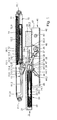
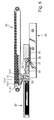
- FIG. 1 shows a feeder, as used for example in drawers are used. Also conceivable is the use in other components to be moved, such as doors, flaps, etc.
- the retraction device comprises a base part 40 and a housing 10, which is fastened to a housing body (not shown) in each case. Furthermore, a Ausschiebean Aunt 20 is provided, which is arranged on a drawer (also not shown).
- the housing 10 is provided with screw 11.1, with which a body-side mounting is possible.
- the housing 10 has two mutually parallel spaced side walls 11, are incorporated in the guides 11.2.
- the guides 11.2 have a slot-shaped opening, which terminates in a widened recess 11.21.
- the guides 11.2 of the two side walls 11 are aligned with each other.
- a damper 12 is housed.
- the damper 12 is designed as a fluid damper, in this case as an air damper.
- the use of an air damper has the advantage that in the event of damage no liquid can escape and contaminate the drawer contents.
- the damper 12 has a cylinder 12.6, in which a piston 12.2 outgoing from the in FIG. 1 shown insertion position be pulled out. During the return movement of the piston 12.2 he works against an air cushion, the air pressure is continuously reduced.
- a small opening in an insert 12.3 is provided, through which the compressed air can escape in a controlled manner.
- the piston rod 12.1 At its end facing away from the insert 12.3, the piston rod 12.1 has a head section 12.4, which forms a pivot bearing 12.5.
- a coupling piece 13 in the form of a tilting element held pivotally.
- the pivoting movement is in this case in accordance with a perpendicular to the image plane FIG. 2 extending pivot axis.
- a spring holder 13.1 is arranged, which holds one end of a spring 14. The other end of the spring 14 is hung on the housing side.
- the coupling piece 13 has a trigger 13.2, which is arranged at a distance from the pivot axis. Furthermore, a driver 13.4 is present on the coupling piece 13, which is formed via a spring element 13.5 on an arm 13.3. With the driver 13.4, a connecting part 30 of a Ausschiebean extract 20 is releasably connectable.
- the Ausschiebean extract 20 includes the connecting part 30, whose task is to produce the detachable coupling with the coupling piece 13.
- the connecting part 30 on a holder 32 has a latch 33 which can be coupled in the region between the trigger 13.2 and the driver 13.4.
- the holder 32 carries by means of a pivot bearing 34, a control 35 in the form of a lever. At its free end facing away from the holder 31, the control 35 is equipped with a rotatable roller 37 and a rotatable blocking roller 38. Between the pivot bearing 34 and the blocking roller 38, a stop 36 is formed.
- On the holder 32 includes a support 31.
- a plunger 24 is held at the end facing away from the holder 32 via a threaded connection.
- the plunger 24 is screwed with an external thread 24.1 in a threaded receptacle of the carrier 31.
- the plunger 24 carries a locking ring 24.2. This is freely rotatably supported in a bearing receptacle of the plunger 24 in the circumferential direction.
- the locking ring 24.2 has a latching element which is guided in a control cam 23 of a hollow cylinder of a sliding piece 21.
- the control cam 23 is incorporated in the form of a groove in the inner wall of the sliding piece 21.
- the control cam 23 and the locking ring 24.2 of the plunger 24 form a Studentshubmechanismus.
- the operation is similar to a ballpoint pen, wherein the plunger 24 forms the push button of the ballpoint pen.
- a spring element 22 is set in the form of a helical spring and secured against buckling on the walls of the hollow cylinder.
- the holder 32 is slidably guided in a linear guide 34.1 with a hinge pin forming the pivot bearing 34.
- the wall forming the linear guide 34.1 carries a shaped piece 39 which forms a mating surface 39.1 and a running surface 39.2.
- the fitting 40 is U-shaped in cross-section. It has a mounting portion 41 with holes 43 for screwing with a furniture body.
- a wall 42 connects perpendicular to.
- the wall 42, the mounting portion 41 and a parallel to this further wall carry an integrally formed, inclined locking surface 46 and a retaining piece 47.
- a locking element 44 is pivotally hinged to the mounting portion 41 and by gravity and / or a spring element 22 in the in Fig. 1 held starting position held.
- the blocking element 44 has two oppositely oriented control cams 44.1, 44.2.
- FIG. 1 shows the starting position of the feeder, thus as the position in which the drawer is in the closed position. This represents the position in which the coupling piece 13 is in the retracted position.
- the overstroke mechanism is in a latching position, wherein the latching ring 24.2 is blocked at a latching projection of the control cam 23.
- the blocking element 35 is held by means of a stop 35.1 on the holder 32 in a raised unlocking position.
- an overstroke Ü in, for example the drawer front is introduced in the direction of the actual drawer closing movement.
- This overstroke Ü is introduced via a sliding piece 21 screwed to the drawer.
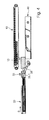
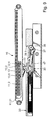
- FIG. 2 shows the Ausschubrium. This movement moves the sliding piece 21 and with it the drawer into a first partial open position (in accordance with Fig. 2 ).
- the drawer can be easily gripped and pulled manually in a further part-opening position or fully in the open position.
- the coupled with the drawer Ausschiebean onion is then moved in the opening direction ⁇ .
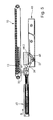
- the coupling piece 13 is coupled to the latch 33 with the Ausschiebean onion 20, and the coupling piece 13 in the opening direction ⁇ (see Fig. 3 ) emotional.
- the coupling piece 13 is guided in the guide 11.2.
- the coupling piece 13 takes the piston rod 12.1 of the damper 11 and thus displaces the piston 12.2.
- the spring is stretched.
- the coupling piece 13 is pulled by the pull-out device 20 until the catch 13.4 guided in the guide 11.2 reaches the region of the cutout 11.21.
- the coupling piece 12 Due to the eccentric to the pivot axis 12.5 acting spring 14, the coupling piece 12 is tilted about the pivot axis 12.5, wherein the driver 13.4 falls into the recess 11.21. He gets out of engagement with holder 32. Since now the connection between the Ausschiebean Aunt 20 and the coupling piece 13 is repealed, the drawer can be pulled out in the freewheel, as Fig. 4 illustrated. In this case, the roller 37 deflects the locking element 44 on its control cam 44.1 and lifts it against the Direction of gravity upwards. The roller 37 passes through the blocking element 44 and the control element 35 leaves the fitting part 40 through the opening 45.
- Fig. 4 shows a further part-opening position.
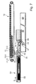
- Fig. 7 shows, due to the further running on the locking element 44 roller 37, the blocking element 35 in its blocking position.
- the blocking roller 38 bears against the mating surface 39.1 and blocks inadvertent release of the push-out arrangement from the push-in position.
- the latch 33 hits immediately after the Ausschiebean eleven21 and the coupling piece 13 is released. Then the guide elements reach 13.6 in the region of the guide 11.2 and the spring 14, the coupling piece 13 pull back into the retraction position. The damper 12 dampens this pull-in movement. With the coupling piece of the bolt 33 is pulled on the driver 13.4 (see Fig. 8 ). In this case, the drawer is pulled over the sliding piece 21 automatically in the closed position. In this by the FIGS. 8 and 9 illustrated Moving process passes over the roller 37, the holding piece 47.
- Fig. 10 is again identical to Fig. 1 and shows the starting position, in which the drawer is ready for a new operation.
- the housing 10 and the fitting 40 are attached to the furniture body. However, it is also conceivable to attach these parts to the drawer. Then, the Ausschiebean Aunt 20 is attached to the other furniture component.
- the arrangement according to the invention may be arranged laterally in the region of one or both of the drawer walls extending in the direction of the drawer movement.
- the feed guide can also be part of the drawer slide. It can also be arranged centrally under the drawer bottom. Then, for example, the Ausschiebean Aunt 20 is held on the drawer front below the drawer bottom.
- the housing 10 is then arranged laterally on the furniture body. The coupling of these components then takes place with the inclusion of a cross member or drawer as a link.
Description
- Die Erfindung betrifft eine Einzugvorrichtung, insbesondere für Schubladen, Schiebetüren, Scharniertüren, etc. mit einem von einer Feder beaufschlagbaren Koppelstück, das zwischen einer Einzugposition und einer Ausstellposition verstellbar ist.
- Die Erfindung betrifft weiterhin ein Verfahren zum Bedienen einer Schublade.
- Aus der
DE 10 2007 008 688 A1 ist eine Einzugvorrichtung für Schubladen bekannt. Diese weist als Koppelstück ein Kippsegment auf, das beim Öffnen einer Schublade gegen die Vorspannung einer Feder von einer Einzugposition in eine Ausstellposition verfahrbar ist. Dabei wird das Kippsegment von einem Mitnehmer bewegt, der schubladenseitig montiert ist. Wenn das Kippsegment die Ausstellposition erreicht hat, gibt es den Mitnehmer frei und die Schublade kann im Freilauf unbeeinflusst von der Einzugvorrichtung weiter ausgezogen werden. Wenn die Schublade wieder geschlossen wird, kann sie im Freilauf verschoben werden, bis der Mitnehmer von dem Kippsegment gefangen wird. - Dann zieht die zuvor gespannte Feder die Schublade in die Schließstellung. Um dabei einen harten Aufprall der Schublade zu verhindern, wird die Einzugbewegung mit einem Dämpfer gebremst.
- Zunehmend werden aus gestalterischen Gründen grifflose Schubladen gewünscht. Mit den bekannten Einzugvorrichtungen lasse sich solche Schubladen nicht immer einfach öffnen, da die Schublade unter Einwirkung der Feder in der Schließstellung gehalten wird.
- Aus der
WO 01/82749 A2 - Es ist Aufgabe der Erfindung, bei einer Schublade oder dergleichen Schiebeelement den Bedienkomfort zu verbessern.
- Diese Aufgabe wird dadurch gelöst, dass mit dem Koppelstück eine Ausschiebeanordnung mittelbar oder unmittelbar koppelbar ist, und dass ein Schiebestück der Ausschiebeanordnung bei Betätigung der Ausschiebeanordnung verstellbar ist. Mittels der Ausschiebeanordnung kann die Schublade aus der Schließstellung heraus in eine Teil-Öffnungsstellung verfahren werden. Dabei wird das Schiebestück wirksam, das die Schublade verstellt. Die teilgeöffnete Schublade lässt sich dann, beispielsweise an der Frontblende greifen und in die Öffnungsstellung ziehen.
- Bei dieser Anordnung kann eine kontrollierte Schließbewegung dadurch erreicht werden, dass ein Dämpfer die Bewegung des Koppelstücks von der Ausstellposition in die Einzugposition dämpft.
- Eine bevorzugte Ausgestaltungsvariante der Erfindung kann dadurch gekennzeichnet sein, dass das Koppelstück in der Ausstellposition mittels einer Stellanordnung in einer Parkposition gehalten ist, und dass in der Parkposition das Schiebstück relativ zum Koppelstück verstellbar ist. Hierdurch ergibt sich für die Einzugvorrichtung ein einfacher Aufbau und der Bedienablauf der Einzugvorrichtung kann vorteilhaft in den Bewegungsablauf der Schublade integriert werden.
- Um einen definierten Bewegungsablauf bei der Betätigung der Ausschiebeanordnung zu erhalten, kann es vorgesehen sein, dass das Schiebestück zwischen einer Ein- und einer Ausschubstellung verstellbar ist.
- Für eine erfindungsgemäße Einzugvorrichtung ergibt sich dann ein einfacher und kostengünstiger Aufbau, wenn vorgesehen ist, dass die Ausschiebeanordnung ein Federelement aufweist, und dass das Federelement das Schiebestück in Einschubstellung vorspannt. Das Federelement kann bei Betätigung der Ausschiebeanordnung in der Schließstellung der Schublade seine Federenergie auf das Schiebestück übertragen. Die Schublade wird damit in die teilgeöffnete Stellung gebracht.
- Eine besonders bevorzugte Erfindungsausgestaltung kann dadurch gekennzeichnet sein, dass die Ausschiebeanordnung einen Überhubmechanismus zur Aufhebung der Einschiebstellung aufweist. Damit kann die Einzugvorrichtung besonders bedienerfreundlich gehandhabt werden. Zum Auslösen der Ausschiebeanordnung kann, je nach Auslegung der Schublade, beispielsweise nur durch Drücken der Schubladenfront der Überhubmechanismus bedient werden.
- Wenn vorgesehen ist, dass die Ausschiebeanordnung einen Träger aufweist, und dass bei einer Verstellung des Schiebestücks von der Ausschiebstellung in die Einschiebstellung ein Steuerelement, insbesondere ein Riegel, wirksam ist, der eine Verstellung des Schiebestücks relativ zu dem Träger ermöglicht, dann kann eine ausgelöste Ausschiebeanordnung auf einfache Weise wieder geladen werden.
- Um eine unbeabsichtigte Auslösung der Ausschiebeanordnung zu verhindern ist eine Erfindungsvariante derart, dass das Schiebestück in der Einschubstellung mittels eines Arretierstücks gesichert.
- Eine bevorzugte Ausgestaltungsvariante der Erfindung ist derart, dass ein Steuerelement der Ausschiebeanordnung beim Schließen der Schublade an einem korpusseitig montierbaren Sperrelement zwischen Verstellung der Ausschiebeanordnung von der Ausschiebstellung in die Einschiebstellung blockiert.
- Ein zuverlässiger Betrieb der Einzugvorrichtung wird dadurch garantiert, dass das Steuerelement die Einschiebstellung der Ausschiebeanordnung zumindest in Teilbereichen durch die Feder bewirkten Verstellung des Koppelstücks sichert.
- Die Betätigung der Ausschiebeanordnung gelingt einfach dadurch, dass das Steuerelement aus der Einzugposition zum Entriegeln der Ausschiebeanordnung gegen ein Haltestück verstellbar ist.
- Die Aufgabe der Erfindung wird auch gelöst mit einem Verfahren zum Bedienen einer Schublade oder dergleichen, wobei in der Schließstellung der Schublade eine Ausschiebeanordnung ausgelöst wird, die die Schublade aus der Schließposition in eine Teil-Öffnungsstellung bewegt, und dass dann bei einer Verstellung der Schublade aus der Teil-Öffnungsstellung eine Feder gespannt wird.
- Hier dient wieder die Ausschiebeanordnung zum bequemen Öffnen der Schublade aus der Schließstellung heraus. Wenn dann die Schublade aus der Teil-Öffnungsstellung heraus gezogen wird, dann wird diese Ziehbewegung zum Spannen der Feder genutzt, die später beim Einziehen der Schublade in die Schließposition entspannt wird.
- Dieser Ablauf lässt sich besonders komfortabel dadurch verwirklichen, dass während des Öffnens der Schublade aus der Teil-Öffnungsstellung ein Koppelstück aus einer Einzugposition in eine Auszugposition gebracht wird, und dass bei Erreichen der Auszugposition das Koppelstück in eine Parkposition gebracht und die Kopplung zwischen der Ausschiebeanordnung und dem Koppelstück aufgehoben wird.
- Der Bedienkomfort ist dann besonders bei grifflosen Schubladen etc. hoch, wenn vorgesehen ist, dass zur Auslösung der Ausschiebeanordnung aus der Schließstellung ein Überhubmechanismus betätigt wird.
- Wenn vorgesehen ist, dass bei einer Bewegung der Schublade aus einer geöffneten oder teilweise geöffneten Stellung in Richtung der Schließstellung die Ausschiebeanordnung von ihrer Ausschiebstellung in die Einschiebstellung gebracht wird, dann wird die Ausschiebeanordnung beim Schließen der Schublade in die Einschiebestellung gebracht, so dass dieser Vorgang in den "natürlichen" Bewegungsablauf der Schublade integriert wird, was als besonders bedienfreundlich empfunden wird.
- Für einen sanften Schließvorgang kann es vorgesehen sein, dass die Ausschiebeanordnung mittels der Feder in die Schließposition der Schublade gezogen und gleichzeitig mittels eines Dämpfers gebremst wird.
- Zum Spannen der Ausschiebeanordnung kann es vorgesehen sein, dass die Ausschiebeanordnung beim Schließen der Schublade etc. mit einem Steuerelement auf ein Sperrelement gefahren wird. Dies ermöglicht einen geringen Teileaufwand.
- Hierbei ist es vorteilhaft, dass das Sperrelement im Innenraum des Korpus auf das Sperrelement gefahren wird. Dadurch wird eine zuverlässige Bedienung und eine geschützte Unterbringung der Betätigungsstelle möglich. Darüber hinaus ergibt sich für den Bediener ein eindeutiger und ohne weiteres nachvollziehbarer Betrieb.
- Eine Erfindungsvariante ist dergestalt, dass die Ausschiebeanordnung unmittelbar bevor das Koppelstück mit der Feder eingezogen wird von der Ausschiebstellung in die Einschiebstellung gebracht wird.
- Die Erfindung wird im Folgenden anhand eines in den Zeichnungen dargestellten Ausführungsbeispieles näher erläutert. Es zeigen:
- Figuren 1 bis 10
- eine Einzugvorrichtung in Seitenansicht, teilweise im Schnitt und in verschiedenen Betriebsstellungen.
-
Figur 1 zeigt eine Einzugvorrichtung, wie sie beispielsweise bei Schubladen zum Einsatz kommt. Denkbar ist auch die Verwendung bei anderen zu bewegenden Bauteilen, wie Türen, Klappen etc.. Die Einzugvorrichtung umfasst ein Basisteil 40 und ein Gehäuse 10, die jeweils an einem Gehäusekorpus (nicht dargestellt) befestigbar ist. Weiterhin ist eine Ausschiebeanordnung 20 vorgesehen, die an einer Schublade (ebenfalls nicht dargestellt) angeordnet ist. - Das Gehäuse 10 ist mit Schraubaufnahmen 11.1 versehen, mit denen eine korpusseitige Befestigung möglich ist. Das Gehäuse 10 hat zwei zueinander parallel beabstandete Seitenwände 11, in die Führungen 11.2 eingearbeitet sind. Dabei weisen die Führungen 11.2 einen schlitzförmigen Durchbruch auf, der in einer verbreiterten Ausnehmung 11.21 ausläuft. Die Führungen 11.2 der beiden Seitenwände 11 fluchten miteinander.
- In dem Gehäuse 10 ist ein Dämpfer 12 untergebracht. Der Dämpfer 12 ist als Fluiddämpfer, vorliegend als Luftdämpfer ausgeführt. Die Verwendung eines Luftdämpfers hat den Vorteil, dass im Schadensfall keine Flüssigkeit austreten und den Schubladeninhalt verschmutzen kann. Der Dämpfer 12 weist einen Zylinder 12.6 auf, in dem ein Kolben 12.2 ausgehende von der in
Figur 1 gezeigten Einschubstellung ausgezogen werden. Bei der Rückbewegung des Kolbens 12.2 arbeitet er gegen ein Luftpolster, wobei der Luftdruck kontinuierlich abgebaut wird. Zu diesem Zweck ist eine kleine Öffnung in einem Einsatz 12.3 vorhanden, durch die die komprimierte Luft kontrolliert entweichen kann. An seinem dem Einsatz 12.3 abgewandten Ende besitzt die Kolbenstange 12.1 einen Kopfabschnitt 12.4, der ein Schwenklager 12.5 bildet. An dem Schwenklager 12.5 ist ein Koppelstück 13 in Form eines Kippelementes schwenkbar gehalten. Die Schwenkbewegung verläuft dabei um eine senkrecht zur Bildebene gemäßFigur 2 verlaufende Schwenkachse. An dem Koppelstück 13 ist ein Federhalter 13.1 angeordnet, der ein Ende einer Feder 14 hält. Das andere Ende der Feder 14 ist gehäuseseitig aufgehangen. - Das Koppelstück 13 besitzt einen Auslöser 13.2, der im Abstand zur Schwenkachse angeordnet ist. Weiterhin ist am Koppelstück 13 ein Mitnehmer 13.4 vorhanden, der über ein Federelement 13.5 an einem Arm 13.3 angeformt ist. Mit dem Mitnehmer 13.4 ist ein Verbindungsteil 30 einer Ausschiebeanordnung 20 lösbar verbindbar.
- Die Ausschiebeanordnung 20 umfasst das Verbindungsteil 30, dessen Aufgabe darin besteht, die lösbare Kopplung mit dem Koppelstück 13 herzustellen. Hierzu weist das Verbindungsteil 30 an einem Halter 32 einen Riegel 33 auf, der im Bereich zwischen dem Auslöser 13.2 und dem Mitnehmer 13.4 einkoppelbar ist. Weiterhin trägt der Halter 32 mittels einer Schwenklagerung 34 ein Steuerelement 35 in Form eines Hebels. An seinem dem Halter 31 abgewandten freien Ende ist das Steuerelement 35 mit einer drehbaren Laufrolle 37 und einer drehbaren Blockierrolle 38 bestückt. Zwischen der Schwenklagerung 34 und der Blockierrolle 38 ist ein Anschlag 36 angeformt. An dem Halter 32 schließt ein Träger 31 an.
- An dem Träger 31 ist an dem dem Halter 32 abgewandeten Ende über eine Gewindeverbindung ein Stößel 24 gehalten. Dazu ist der Stößel 24 mit einem Außengewinde 24.1 in eine Gewindeaufnahme des Trägers 31 eingeschraubt. Der Stößel 24 trägt einen Rastring 24.2. Dieser ist in einer Lageraufnahme des Stößels 24 in Umfangsrichtung frei drehbar gehalten. Der Rastring 24.2 weist ein Rastelement auf, das in einer Steuerkurve 23 eines Hohlzylinders eines Schiebestücks 21 geführt ist. Dabei ist die Steuerkurve 23 in Form einer Nut in die Innenwandung des Schiebestücks 21 eingearbeitet. Die Steuerkurve 23 und der Rastring 24.2 des Stößels 24 bilden einen Überhubmechanismus. Die Funktionsweise ist dabei ähnlich wie bei einem Kugelschreiber, wobei der Stößel 24 den Druckknopf des Kugelschreibers bildet. In dem Schiebestück 21 ist ein Federelement 22 in Form einer Schraubenfeder eingestellt und an den Wandungen des Hohlzylinders gegen Ausknicken gesichert.
- Der Halter 32 ist mit einem die Schwenklagerung 34 bildenden Scharnierstift in einer Linearführung 34.1 verschiebbar geführt. Die die Linearführung 34.1 bildende Wand trägt ein Formstück 39, das eine Gegenfläche 39.1 und eine Lauffläche 39.2 bildet. Das Beschlagteil 40 ist im Querschnitt U-förmig ausgebildet. Es weist einen Befestigungsabschnitt 41 mit Bohrungen 43 zum Verschrauben mit einem Möbelkorpus auf. An dem Befestigungsabschnitt 41 schließt eine Wandung 42 senkrecht an. Die Wandung 42, der Befestigungsabschnitt 41 und eine zu diesem parallele weitere Wandung tragen eine angeformte, schräg stehende Sperrfläche 46 sowie ein Haltestück 47. Weiterhin ist ein Sperrelement 44 an dem Befestigungsabschnitt 41 schwenkbar angelenkt und mittels Schwerkraft und/oder einem Federelement 22 in der in
Fig. 1 gezeigten Ausgangslage gehalten. Das Sperrelement 44 weist zwei entgegengesetzt orientierte Steuerkurven 44.1, 44.2 auf. - Unter Bezugnahme auf die
Figuren 1 bis 10 wird nachfolgend die Funktionsweise der erfindungsgemäßen Einzugvorrichtung näher erläutert. - Die
Figur 1 zeigt die Ausgangsstellung der Einzugvorrichtung, mithin als die Position in der sich die Schublade in der Schließstellung befindet. Dies stellt die Position dar, in der sich das Koppelstück 13 in der Einzugposition befindet. Der Überhubmechanismus befindet sich in einer Rastposition, wobei der Rastring 24.2 an einem Rastansatz der Steuerkurve 23 blockiert ist. Das Sperrelement 35 ist mittels eines Anschlages 35.1 an dem Halter 32 in einer angehobenen Entriegelungsposition gehalten. Zur Freigabe des Überhubmechanismus wird ein Überhub Ü in, beispielsweise die Schubladenfront in Richtung der eigentlichen Schubladenschließbewegung eingebracht. Dieser Überhub Ü wird über ein mit der Schublade verschraubtes Schiebestück 21 eingebracht. Dabei verschiebt sich das Schiebestück 21 ein kleines Stück weit entgegen die Vorspannung des Federelementes 22 in Richtung des Überhubs Ü gegenüber dem Stößel 24. Dadurch wird die Rastposition des Rastringes 24.2 in der Steuerkurve 23 aufgehoben und der Rastring 24.2 in Umfangsrichtung verdreht, bis er in einen Linearabschnitt der Steuerkurve 23 gelangt. Um den Überhub Ü durchführen zu können, stützt sich der Riegel 33 an dem Auslöser 13.2 ab. - Wenn nun die gedrückte Schublade entlastet wird, dann wird aufgrund der gelösten Rastverbindung zwischen dem Rastring 24.2 und der Steuerkurve 23 das Schiebestück 21 von seiner Einschubstellung (
Figur 4 ) in die Ausschubstellung gebracht. Diese Verstellung S wird durch das Federelement 22 bewirkt, das das Schiebstück 21 vorgespannt in der Einschubstellung hält. -
Figur 2 zeigt die Ausschubstellung. Diese Bewegung bewegt das Schiebestück 21 und mit ihm die Schublade in eine erste Teilöffnungsstellung (gemäßFig. 2 ). - Bei dieser Verstellung bleibt der Halter 32 und mit diesem der Träger 31 stehen, und demgegenüber wird die Linearführung 34.1 (in
Fig. 1 nach links) verschoben. Die Schiebebewegung S wird mit dem Anschlag 36 begrenzt, der an der Gegenfläche 39.1 anschlägt. Diese Stellung zeigtFig. 2 . - Wenn die in
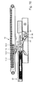
Figur 2 gezeigte Position erreicht ist, kann die Schublade bequem gegriffen und manuell in eine weitere Teil-Öffnungsstellung oder vollständig in die Öffnungsstellung gezogen werden. Dabei wird dann die mit der Schublade gekoppelte Ausschiebeanordnung in Öffnungsrichtung Ö bewegt. Da das Koppelstück 13 mit dem Riegel 33 mit der Ausschiebeanordnung 20 gekoppelt ist, wird auch das Koppelstück 13 in Öffnungsrichtung Ö (sieheFig. 3 ) bewegt. Dabei wird das Koppelstück 13 in der Führung 11.2 geführt. Das Koppelstück 13 nimmt die Kolbenstange 12.1 des Dämpfers 11 mit und verschiebt somit den Kolben 12.2. Gleichzeitig wird auch die Feder gespannt. Das Koppelstück 13 wird solange von der Ausziehvorrichtung 20 gezogen, bis der in der Führung 11.2 geführte Mitnehmer 13.4 in den Bereich der Ausnehmung 11.21 gelangt. Bedingt durch die exzentrisch zur Schwenkachse 12.5 wirkende Feder 14 wird das Koppelstück 12 um die Schwenkachse 12.5 gekippt, wobei der Mitnehmer 13.4 in die Ausnehmung 11.21 fällt. Dabei gelangt er außer Eingriff mit Halter 32. Da nun die Verbindung zwischen der Ausschiebeanordnung 20 und dem Koppelstück 13 aufgehoben ist, kann die Schublade im Freilauf weiter ausgezogen werden, wieFig. 4 veranschaulicht. Dabei lenkt auch die Laufrolle 37 das Sperrelement 44 an seiner Steuerkurve 44.1 aus und hebt es gegen die Schwerkraftrichtung nach oben. Die Laufrolle 37 passiert das Sperrelement 44 und das Steuerelement 35 verlässt das Beschlagteil 40 durch die Öffnung 45. -
Fig. 4 zeigt eine weitere Teil-Öffnungsstellung. - Beim Schließen der Schublade (Schließrichtung S) und somit beim Übergang der Einzugvorrichtung von
Figur 4 nachFigur 5 trifft die Laufrolle 37 auf die Steuerkurve 44.2 des in diese Richtung gesperrten Sperrelements 44. Sie läuft dort entgegen der Schwerkraftrichtung auf, bis die Blockierrolle 38 auf die Lauffläche 39.2 trifft, wie diesFig. 6 zeigt. Nun kann das Verbindungsteil 30 nicht mehr weiter in Schließrichtung S geschoben werden. Die Schließbewegung S bewirkt nun, dass sich der Stößel 24 in das Schiebestück 21 einschiebt, wobei das Federelement 22 gespannt wird, bis der Stößel 24 seine Rastposition (Rastring 24.2 und Steuerkurve 23) findet. Dann ist die Ausschiebeanordnung 20 wieder gespannt und befindet sich in ihrer Einschubstellung. Bei diesem Vorgang rollt die Blockierrolle 38 auf der Lauffläche 39.2 ab, bis sie am Ende der Lauffläche 39.2 eine Kante 39.3 überfährt, die sie in die Gegenfläche 39.1 überführt. - Dabei schwenkt dann, wie
Fig. 7 zeigt, bedingt durch die weiter auf dem Sperrelement 44 auflaufende Laufrolle 37 das Sperrelement 35 in seine Sperrstellung. Dabei liegt die Blockierrolle 38 an der Gegenfläche 39.1 an und blockiert ein unbeabsichtigtes Auslösen der Ausschiebeanordnung aus der Einschiebstellung. - Wie die
Fig. 7 zeigt, trifft der Riegel 33 unmittelbar, nachdem die Ausschiebeanordnung 20 gespannt wurde, auf den Auslöser 13.2 und verkippt diesen um das Schwenklager 12.5. Dabei werden die Führungselemente 13.2 aus der Ausnehmung 11.21 ausgehoben und das Koppelstück 13 freigegeben. Dann gelangen die Führungselemente 13.6 in den Bereich der Führung 11.2 und die Feder 14 kann das Koppelstück 13 zurück in die Einzugposition ziehen. Der Dämpfer 12 dämpft diese Einziehbewegung. Mit dem Koppelstück wird der Riegel 33 an dem Mitnehmer 13.4 gezogen (sieheFig. 8 ). Dabei wird auch die Schublade über das Schiebestück 21 selbsttätig in die Schließstellung gezogen. Bei diesem durch dieFiguren 8 und9 veranschaulichten Bewegungsvorgang überfährt die Laufrolle 37 das Haltestück 47. In der Schließstellung der Schublade fällt das Steuerelement 35 schwerkraftbedingt und/oder durch Federeinwirkung in den Bereich unterhalb des Haltestücks 47, wieFig. 10 zeigt.Fig. 10 ist wieder identisch zuFig. 1 und zeigt die Ausgangsstellung, in der die Schublade zu einer erneuten Bedienung bereit ist. - Üblicherweise sind das Gehäuse 10 und das Beschlagteil 40 am Möbelkorpus befestigt. Es ist jedoch auch denkbar, diese Teile an der Schublade zu befestigen. Dann wird auch die Ausschiebeanordnung 20 am jeweils anderen Möbelbauteil angebracht.
- Die erfindungsgemäße Anordnung kann seitlich im Bereich einer oder beider der in Schubladenbewegungsrichtung verlaufenden Schubladenwände angeordnet sein. Die Einzugführung kann auch Teil der Auszugführung der Schublade sein. Sie kann weiterhin auch zentral unter dem Schubladenboden angeordnet sein. Dann ist beispielsweise die Ausschiebeanordnung 20 an der Schubladenfront unterhalb des Schubladenbodens gehalten. Das Gehäuse 10 ist dann seitlich am Möbelkorpus angeordnet. Die Kopplung dieser Bauteile findet dann unter Einbeziehung eines Querträgers oder Schublade als Verbindungsglied statt.
Claims (20)
- Einzugvorrichtung, insbesondere für Schubladen, Schiebetüren, Scharniertüren, etc. mit einem von einer Feder (13) beaufschlagbaren Koppelstück (13), das zwischen einer Einzugposition und einer Ausstellposition verstellbar ist, dadurch gekennzeichnet,
dass mit dem Koppelstück (13) eine Ausschiebeanordnung (20) mittelbar oder unmittelbar koppelbar ist, und
dass ein Schiebestück (21) der Ausschiebeanordnung (20) bei Betätigung der Ausschiebeanordnung (20) verstellbar ist. - Einzugvorrichtung nach Anspruch 1,
dadurch gekennzeichnet,
dass ein Dämpfer (12) die Bewegung des Koppelstücks (13) von der Ausstellposition in die Einzugposition dämpft. - Einzugvorrichtung nach Anspruch 1 oder 2,
dadurch gekennzeichnet,
dass das Koppelstück (13) in der Ausstellposition mittels einer Stellanordnung (Ausnehmung (11.21), Führung (11.2), Mitnehmer (13.4)) in einer Parkposition gehalten ist, und
dass in der Parkposition das Schiebstück (21) relativ zum Koppelstück (13) verstellbar ist. - Einzugvorrichtung nach einem der Ansprüche 1 bis 3,
dadurch gekennzeichnet,
dass das Schiebestück (21) zwischen einer Ein- und einer Ausschubstellung verstellbar ist. - Einzugvorrichtung nach einem der Ansprüche 1 bis 4,
dadurch gekennzeichnet,
dass die Ausschiebeanordnung (20) ein Federelement (22) aufweist, und dass das Federelement (22) das Schiebestück (21) in Einschubstellung vorspannt. - Einzugvorrichtung nach einem der Ansprüche 1 bis 5,
dadurch gekennzeichnet,
dass die Ausschiebeanordnung (20) einen Überhubmechanismus zur Aufhebung der Einschiebstellung aufweist. - Einzugvorrichtung nach einem der Ansprüche 1 bis 6,
dadurch gekennzeichnet,
dass die Ausschiebeanordnung (20) einen Träger (31) aufweist, und dass bei einer Verstellung des Schiebestücks (21) von der Ausschiebstellung in die Einschiebstellung ein Riegel oder Steuerelement (35) wirksam ist, der eine Verstellung des Schiebestücks (21) relativ zu dem Träger (31) ermöglicht. - Einzugvorrichtung nach einem der Ansprüche 1 bis 7,
dadurch gekennzeichnet,
dass das Schiebestück (21) in der Einschubstellung mittels eines Arretierstücks (39) gesichert ist. - Einzugvorrichtung nach einem der Ansprüche 1 bis 8,
dadurch gekennzeichnet,
dass ein Steuerelement (35) der Ausschiebeanordnung (20) beim Schließen der Schublade an einem korpusseitig montierbaren Sperrelement (44) zwischen Verstellung der Ausschiebeanordnung (20) von der Ausschiebstellung in die Einschiebstellung blockiert. - Einzugvorrichtung nach Anspruch 9,
dadurch gekennzeichnet,
dass das Steuerelement (35) die Einschiebstellung der Ausschiebeanordnung (20) zumindest in Teilbereichen durch die Feder (13) bewirkten Verstellung des Koppelstücks (13) sichert. - Einzugvorrichtung nach Anspruch 9 oder 10,
dadurch gekennzeichnet,
dass das Steuerelement (35) aus der Einzugposition zum Entriegeln der Ausschiebeanordnung (20) gegen ein Haltestück (47) verstellbar ist. - Verfahren zum Bedienen einer Schublade oder dergleichen mit einer Einzugvorrichtung nach einem der Ansprüche 1 bis 11,
wobei in der Schließstellung der Schublade eine Ausschiebeanordnung (20) ausgelöst wird, die die Schublade aus der Schließposition in eine Teil-Öffnungsstellung bewegt, und
dass dann bei einer Verstellung der Schublade aus der Teil-Öffnungsstellung eine Feder (14) gespannt wird. - Verfahren nach Anspruch 12,
dadurch gekennzeichnet,
dass während des Öffnens der Schublade aus der Teil-Öffnungsstellung ein Koppelstück (13) aus einer Einzugposition in eine Auszugposition gebracht wird, und
dass bei Erreichen der Auszugposition das Koppelstück (13) in eine Parkposition gebracht und die Kopplung zwischen der Ausschiebeanordnung (20) und dem Koppelstück (13) aufgehoben wird. - Verfahren nach Anspruch 12 oder 13,
dadurch gekennzeichnet,
dass zur Auslösung der Ausschiebeanordnung (20) aus der Schließstellung ein Überhubmechanismus betätigt wird. - Verfahren nach einem der Ansprüche 12 bis 14,
dadurch gekennzeichnet,
dass bei einer Bewegung der Schublade aus einer geöffneten oder teilweise geöffneten Stellung in Richtung der Schließstellung die Ausschiebeanordnung (20) von ihrer Ausschiebstellung in die Einschiebstellung gebracht wird. - Verfahren nach einem der Ansprüche 12 bis 15,
dadurch gekennzeichnet,
dass die Ausschiebeanordnung (20) mittels der Feder (14) in die Schließposition der Schublade gezogen und gleichzeitig mittels eines Dämpfers (12) gebremst wird. - Verfahren nach einem der Ansprüche 12 bis 16,
dadurch gekennzeichnet,
dass die Ausschiebeanordnung (20) beim Schließen der Schublade etc. mit einem Steuerelement (35) auf ein Sperrelement (44) gefahren wird. - Verfahren nach Anspruch 17,
dadurch gekennzeichnet,
dass das Sperrelement (44) im Innenraum des Korpus auf das Sperrelement (44) gefahren wird. - Verfahren nach einem der Ansprüche 12 bis 18,
dadurch gekennzeichnet,
dass die Ausschiebeanordnung (20) unmittelbar bevor das Koppelstück (13) mit der Feder (14) eingezogen wird von der Ausschiebestellung in die Einschiebstellung gebracht wird. - Verfahren gemäß einem der Ansprüche 12 bis 19,
gekennzeichnet durch einen der Ansprüche 1 bis 11.
Priority Applications (1)
| Application Number | Priority Date | Filing Date | Title |
|---|---|---|---|
| PL10714442T PL2413741T3 (pl) | 2009-04-04 | 2010-04-01 | Urządzenie do wciągania |
Applications Claiming Priority (4)
| Application Number | Priority Date | Filing Date | Title |
|---|---|---|---|
| DE202009004712 | 2009-04-04 | ||
| DE102009016427.8A DE102009016427B4 (de) | 2009-04-04 | 2009-04-04 | Verfahren zum Bedienen einer Schublade |
| DE102009021202.7A DE102009021202B4 (de) | 2009-04-04 | 2009-05-13 | Einzugvorrichtung |
| PCT/EP2010/054441 WO2010112593A1 (de) | 2009-04-04 | 2010-04-01 | Einzugvorrichtung |
Publications (2)
| Publication Number | Publication Date |
|---|---|
| EP2413741A1 EP2413741A1 (de) | 2012-02-08 |
| EP2413741B1 true EP2413741B1 (de) | 2015-07-08 |
Family
ID=45440657
Family Applications (1)
| Application Number | Title | Priority Date | Filing Date |
|---|---|---|---|
| EP10714442.0A Active EP2413741B1 (de) | 2009-04-04 | 2010-04-01 | Einzugvorrichtung |
Country Status (4)
| Country | Link |
|---|---|
| EP (1) | EP2413741B1 (de) |
| JP (1) | JP5606519B2 (de) |
| PL (1) | PL2413741T3 (de) |
| WO (1) | WO2010112593A1 (de) |
Families Citing this family (2)
| Publication number | Priority date | Publication date | Assignee | Title |
|---|---|---|---|---|
| CN108050759B (zh) * | 2017-11-30 | 2019-10-01 | 青岛海尔股份有限公司 | 冰箱及其抽屉组件 |
| CN108332500B (zh) * | 2017-11-30 | 2019-09-27 | 青岛海尔股份有限公司 | 冰箱及其抽屉组件 |
Family Cites Families (4)
| Publication number | Priority date | Publication date | Assignee | Title |
|---|---|---|---|---|
| AU2001259231A1 (en) * | 2000-05-01 | 2001-11-12 | Accuride International, Inc. | Self-closing slide and mechanism for a self-closing slide |
| DE202004018189U1 (de) * | 2004-11-23 | 2005-03-03 | Vauth-Sagel Holding Gmbh & Co. Kg | Einzugshilfe für einen Auszug |
| DE102007008688A1 (de) * | 2007-02-20 | 2008-08-21 | Karl Simon Gmbh & Co. Kg | Einzugvorrichtung für Schiebelemente |
| JP5081563B2 (ja) * | 2007-10-05 | 2012-11-28 | 日本アキュライド株式会社 | 移動側部材の摺動装置 |
-
2010
- 2010-04-01 WO PCT/EP2010/054441 patent/WO2010112593A1/de active Application Filing
- 2010-04-01 JP JP2012502698A patent/JP5606519B2/ja not_active Expired - Fee Related
- 2010-04-01 EP EP10714442.0A patent/EP2413741B1/de active Active
- 2010-04-01 PL PL10714442T patent/PL2413741T3/pl unknown
Also Published As
| Publication number | Publication date |
|---|---|
| EP2413741A1 (de) | 2012-02-08 |
| JP2012522552A (ja) | 2012-09-27 |
| WO2010112593A1 (de) | 2010-10-07 |
| JP5606519B2 (ja) | 2014-10-15 |
| PL2413741T3 (pl) | 2015-12-31 |
Similar Documents
| Publication | Publication Date | Title |
|---|---|---|
| EP2488062B1 (de) | Schiebeanordnung | |
| EP2413740B1 (de) | Einzugvorrichtung | |
| AT395095B (de) | Schliessvorrichtung fuer schubladen | |
| EP2001327B1 (de) | Antriebsmechanismus für ein in oder an einem möbel bewegbar gelagertes möbelteil | |
| AT514065B1 (de) | Antriebsvorrichtung für ein bewegbares Möbelteil | |
| EP2996514B1 (de) | Schiebeanordnung | |
| EP3141153B1 (de) | Vorrichtung zum bewegen eines bewegbaren möbelteils in eine öffnungsrichtung in bezug zu einem möbelkorpus eines möbels | |
| EP2649261B1 (de) | SCHLIEß- UND DÄMPFUNGSVORRICHTUNG FÜR BEWEGBARE MÖBELTEILE | |
| DE102016008044A1 (de) | Elektrisches Haushaltsgerät, insbesondere Geschirrspülmaschine | |
| AT8213U1 (de) | Einzugsautomatik für schubladen-ausziehführungen | |
| EP1127514A1 (de) | Vorrichtung zum Öffnen einer Möbelabdeckung, wie z.B. einer Schublade, Tür oder Klappe | |
| EP3142516B1 (de) | Einzugsvorrichtung für möbel | |
| DE102009021202B4 (de) | Einzugvorrichtung | |
| EP2793655B1 (de) | Anordnung zum bewegen eines bewegbaren möbelteils | |
| DE102011050605B4 (de) | Schiebeanordnung | |
| EP2843164B1 (de) | Beschlag für ein Schubladenmodul eines mobilen Fahrzeuges | |
| EP2413741B1 (de) | Einzugvorrichtung | |
| EP1959793A1 (de) | Einzugsvorrichtung für ein in einem möbelkorpus längs verschiebbar geführtes auszugsteil | |
| EP3675691B1 (de) | Einzugsvorrichtung zum einziehen eines bewegbaren teils eines möbels oder haushaltsgeräts in eine endlage | |
| WO2015096890A1 (de) | Vorrichtung zum öffnen eines bewegbaren möbelteils | |
| EP1787548A1 (de) | Tisch mit verschiebbarer Tischplatte und Sicherungseinrichtung | |
| AT13569U1 (de) | Ausstoßvorrichtung für ein bewegbares Möbelteil |
Legal Events
| Date | Code | Title | Description |
|---|---|---|---|
| PUAI | Public reference made under article 153(3) epc to a published international application that has entered the european phase |
Free format text: ORIGINAL CODE: 0009012 |
|
| 17P | Request for examination filed |
Effective date: 20111104 |
|
| AK | Designated contracting states |
Kind code of ref document: A1 Designated state(s): AT BE BG CH CY CZ DE DK EE ES FI FR GB GR HR HU IE IS IT LI LT LU LV MC MK MT NL NO PL PT RO SE SI SK SM TR |
|
| DAX | Request for extension of the european patent (deleted) | ||
| GRAP | Despatch of communication of intention to grant a patent |
Free format text: ORIGINAL CODE: EPIDOSNIGR1 |
|
| INTG | Intention to grant announced |
Effective date: 20150420 |
|
| GRAS | Grant fee paid |
Free format text: ORIGINAL CODE: EPIDOSNIGR3 |
|
| GRAA | (expected) grant |
Free format text: ORIGINAL CODE: 0009210 |
|
| AK | Designated contracting states |
Kind code of ref document: B1 Designated state(s): AT BE BG CH CY CZ DE DK EE ES FI FR GB GR HR HU IE IS IT LI LT LU LV MC MK MT NL NO PL PT RO SE SI SK SM TR |
|
| REG | Reference to a national code |
Ref country code: GB Ref legal event code: FG4D Free format text: NOT ENGLISH |
|
| REG | Reference to a national code |
Ref country code: AT Ref legal event code: REF Ref document number: 734681 Country of ref document: AT Kind code of ref document: T Effective date: 20150715 Ref country code: CH Ref legal event code: EP |
|
| REG | Reference to a national code |
Ref country code: IE Ref legal event code: FG4D Free format text: LANGUAGE OF EP DOCUMENT: GERMAN |
|
| REG | Reference to a national code |
Ref country code: DE Ref legal event code: R096 Ref document number: 502010009826 Country of ref document: DE |
|
| REG | Reference to a national code |
Ref country code: NL Ref legal event code: MP Effective date: 20150708 |
|
| REG | Reference to a national code |
Ref country code: LT Ref legal event code: MG4D |
|
| REG | Reference to a national code |
Ref country code: PL Ref legal event code: T3 |
|
| REG | Reference to a national code |
Ref country code: DE Ref legal event code: R082 Ref document number: 502010009826 Country of ref document: DE Representative=s name: HERRMANN, JOCHEN, DIPL.-ING., DE |
|
| PG25 | Lapsed in a contracting state [announced via postgrant information from national office to epo] |
Ref country code: LT Free format text: LAPSE BECAUSE OF FAILURE TO SUBMIT A TRANSLATION OF THE DESCRIPTION OR TO PAY THE FEE WITHIN THE PRESCRIBED TIME-LIMIT Effective date: 20150708 Ref country code: NO Free format text: LAPSE BECAUSE OF FAILURE TO SUBMIT A TRANSLATION OF THE DESCRIPTION OR TO PAY THE FEE WITHIN THE PRESCRIBED TIME-LIMIT Effective date: 20151008 Ref country code: GR Free format text: LAPSE BECAUSE OF FAILURE TO SUBMIT A TRANSLATION OF THE DESCRIPTION OR TO PAY THE FEE WITHIN THE PRESCRIBED TIME-LIMIT Effective date: 20151009 Ref country code: LV Free format text: LAPSE BECAUSE OF FAILURE TO SUBMIT A TRANSLATION OF THE DESCRIPTION OR TO PAY THE FEE WITHIN THE PRESCRIBED TIME-LIMIT Effective date: 20150708 Ref country code: FI Free format text: LAPSE BECAUSE OF FAILURE TO SUBMIT A TRANSLATION OF THE DESCRIPTION OR TO PAY THE FEE WITHIN THE PRESCRIBED TIME-LIMIT Effective date: 20150708 |
|
| PG25 | Lapsed in a contracting state [announced via postgrant information from national office to epo] |
Ref country code: HR Free format text: LAPSE BECAUSE OF FAILURE TO SUBMIT A TRANSLATION OF THE DESCRIPTION OR TO PAY THE FEE WITHIN THE PRESCRIBED TIME-LIMIT Effective date: 20150708 Ref country code: IS Free format text: LAPSE BECAUSE OF FAILURE TO SUBMIT A TRANSLATION OF THE DESCRIPTION OR TO PAY THE FEE WITHIN THE PRESCRIBED TIME-LIMIT Effective date: 20151108 Ref country code: SE Free format text: LAPSE BECAUSE OF FAILURE TO SUBMIT A TRANSLATION OF THE DESCRIPTION OR TO PAY THE FEE WITHIN THE PRESCRIBED TIME-LIMIT Effective date: 20150708 Ref country code: PT Free format text: LAPSE BECAUSE OF FAILURE TO SUBMIT A TRANSLATION OF THE DESCRIPTION OR TO PAY THE FEE WITHIN THE PRESCRIBED TIME-LIMIT Effective date: 20151109 Ref country code: ES Free format text: LAPSE BECAUSE OF FAILURE TO SUBMIT A TRANSLATION OF THE DESCRIPTION OR TO PAY THE FEE WITHIN THE PRESCRIBED TIME-LIMIT Effective date: 20150708 |
|
| REG | Reference to a national code |
Ref country code: DE Ref legal event code: R097 Ref document number: 502010009826 Country of ref document: DE |
|
| PG25 | Lapsed in a contracting state [announced via postgrant information from national office to epo] |
Ref country code: CZ Free format text: LAPSE BECAUSE OF FAILURE TO SUBMIT A TRANSLATION OF THE DESCRIPTION OR TO PAY THE FEE WITHIN THE PRESCRIBED TIME-LIMIT Effective date: 20150708 Ref country code: SK Free format text: LAPSE BECAUSE OF FAILURE TO SUBMIT A TRANSLATION OF THE DESCRIPTION OR TO PAY THE FEE WITHIN THE PRESCRIBED TIME-LIMIT Effective date: 20150708 Ref country code: DK Free format text: LAPSE BECAUSE OF FAILURE TO SUBMIT A TRANSLATION OF THE DESCRIPTION OR TO PAY THE FEE WITHIN THE PRESCRIBED TIME-LIMIT Effective date: 20150708 Ref country code: EE Free format text: LAPSE BECAUSE OF FAILURE TO SUBMIT A TRANSLATION OF THE DESCRIPTION OR TO PAY THE FEE WITHIN THE PRESCRIBED TIME-LIMIT Effective date: 20150708 |
|
| PLBE | No opposition filed within time limit |
Free format text: ORIGINAL CODE: 0009261 |
|
| STAA | Information on the status of an ep patent application or granted ep patent |
Free format text: STATUS: NO OPPOSITION FILED WITHIN TIME LIMIT |
|
| PG25 | Lapsed in a contracting state [announced via postgrant information from national office to epo] |
Ref country code: RO Free format text: LAPSE BECAUSE OF FAILURE TO SUBMIT A TRANSLATION OF THE DESCRIPTION OR TO PAY THE FEE WITHIN THE PRESCRIBED TIME-LIMIT Effective date: 20150708 |
|
| 26N | No opposition filed |
Effective date: 20160411 |
|
| PG25 | Lapsed in a contracting state [announced via postgrant information from national office to epo] |
Ref country code: SI Free format text: LAPSE BECAUSE OF FAILURE TO SUBMIT A TRANSLATION OF THE DESCRIPTION OR TO PAY THE FEE WITHIN THE PRESCRIBED TIME-LIMIT Effective date: 20150708 Ref country code: BE Free format text: LAPSE BECAUSE OF NON-PAYMENT OF DUE FEES Effective date: 20160430 |
|
| REG | Reference to a national code |
Ref country code: DE Ref legal event code: R079 Ref document number: 502010009826 Country of ref document: DE Free format text: PREVIOUS MAIN CLASS: A47B0088040000 Ipc: A47B0088400000 |
|
| REG | Reference to a national code |
Ref country code: CH Ref legal event code: PL |
|
| GBPC | Gb: european patent ceased through non-payment of renewal fee |
Effective date: 20160401 |
|
| PG25 | Lapsed in a contracting state [announced via postgrant information from national office to epo] |
Ref country code: LU Free format text: LAPSE BECAUSE OF FAILURE TO SUBMIT A TRANSLATION OF THE DESCRIPTION OR TO PAY THE FEE WITHIN THE PRESCRIBED TIME-LIMIT Effective date: 20160401 |
|
| REG | Reference to a national code |
Ref country code: IE Ref legal event code: MM4A |
|
| REG | Reference to a national code |
Ref country code: FR Ref legal event code: ST Effective date: 20161230 |
|
| PG25 | Lapsed in a contracting state [announced via postgrant information from national office to epo] |
Ref country code: GB Free format text: LAPSE BECAUSE OF NON-PAYMENT OF DUE FEES Effective date: 20160401 Ref country code: FR Free format text: LAPSE BECAUSE OF NON-PAYMENT OF DUE FEES Effective date: 20160502 Ref country code: CH Free format text: LAPSE BECAUSE OF NON-PAYMENT OF DUE FEES Effective date: 20160430 Ref country code: LI Free format text: LAPSE BECAUSE OF NON-PAYMENT OF DUE FEES Effective date: 20160430 |
|
| PG25 | Lapsed in a contracting state [announced via postgrant information from national office to epo] |
Ref country code: IE Free format text: LAPSE BECAUSE OF NON-PAYMENT OF DUE FEES Effective date: 20160401 |
|
| REG | Reference to a national code |
Ref country code: AT Ref legal event code: MM01 Ref document number: 734681 Country of ref document: AT Kind code of ref document: T Effective date: 20160401 |
|
| PG25 | Lapsed in a contracting state [announced via postgrant information from national office to epo] |
Ref country code: NL Free format text: LAPSE BECAUSE OF FAILURE TO SUBMIT A TRANSLATION OF THE DESCRIPTION OR TO PAY THE FEE WITHIN THE PRESCRIBED TIME-LIMIT Effective date: 20150708 |
|
| PG25 | Lapsed in a contracting state [announced via postgrant information from national office to epo] |
Ref country code: AT Free format text: LAPSE BECAUSE OF NON-PAYMENT OF DUE FEES Effective date: 20160401 |
|
| PG25 | Lapsed in a contracting state [announced via postgrant information from national office to epo] |
Ref country code: SM Free format text: LAPSE BECAUSE OF FAILURE TO SUBMIT A TRANSLATION OF THE DESCRIPTION OR TO PAY THE FEE WITHIN THE PRESCRIBED TIME-LIMIT Effective date: 20150708 Ref country code: CY Free format text: LAPSE BECAUSE OF FAILURE TO SUBMIT A TRANSLATION OF THE DESCRIPTION OR TO PAY THE FEE WITHIN THE PRESCRIBED TIME-LIMIT Effective date: 20150708 Ref country code: HU Free format text: LAPSE BECAUSE OF FAILURE TO SUBMIT A TRANSLATION OF THE DESCRIPTION OR TO PAY THE FEE WITHIN THE PRESCRIBED TIME-LIMIT; INVALID AB INITIO Effective date: 20100401 |
|
| PG25 | Lapsed in a contracting state [announced via postgrant information from national office to epo] |
Ref country code: MC Free format text: LAPSE BECAUSE OF FAILURE TO SUBMIT A TRANSLATION OF THE DESCRIPTION OR TO PAY THE FEE WITHIN THE PRESCRIBED TIME-LIMIT Effective date: 20150708 Ref country code: MK Free format text: LAPSE BECAUSE OF FAILURE TO SUBMIT A TRANSLATION OF THE DESCRIPTION OR TO PAY THE FEE WITHIN THE PRESCRIBED TIME-LIMIT Effective date: 20150708 Ref country code: MT Free format text: LAPSE BECAUSE OF FAILURE TO SUBMIT A TRANSLATION OF THE DESCRIPTION OR TO PAY THE FEE WITHIN THE PRESCRIBED TIME-LIMIT Effective date: 20150708 |
|
| PG25 | Lapsed in a contracting state [announced via postgrant information from national office to epo] |
Ref country code: BG Free format text: LAPSE BECAUSE OF FAILURE TO SUBMIT A TRANSLATION OF THE DESCRIPTION OR TO PAY THE FEE WITHIN THE PRESCRIBED TIME-LIMIT Effective date: 20150708 |
|
| PGFP | Annual fee paid to national office [announced via postgrant information from national office to epo] |
Ref country code: PL Payment date: 20200331 Year of fee payment: 11 |
|
| REG | Reference to a national code |
Ref country code: DE Ref legal event code: R082 Ref document number: 502010009826 Country of ref document: DE Representative=s name: HERRMANN, JOCHEN, DIPL.-ING., DE Ref country code: DE Ref legal event code: R081 Ref document number: 502010009826 Country of ref document: DE Owner name: TITUS D.O.O. DEKANI, SI Free format text: FORMER OWNER: KARL SIMON GMBH & CO. KG, 78733 AICHHALDEN, DE |
|
| PG25 | Lapsed in a contracting state [announced via postgrant information from national office to epo] |
Ref country code: PL Free format text: LAPSE BECAUSE OF NON-PAYMENT OF DUE FEES Effective date: 20210401 |
|
| PGFP | Annual fee paid to national office [announced via postgrant information from national office to epo] |
Ref country code: TR Payment date: 20230330 Year of fee payment: 14 |
|
| P01 | Opt-out of the competence of the unified patent court (upc) registered |
Effective date: 20230517 |
|
| PGFP | Annual fee paid to national office [announced via postgrant information from national office to epo] |
Ref country code: IT Payment date: 20230426 Year of fee payment: 14 Ref country code: DE Payment date: 20230420 Year of fee payment: 14 |