EP3645928B1 - Vorrichtung zum ableiten oder entfernen von wasser aus einem wasserrohr mit kreisförmigem querschnitt sowie ihre verwendung - Google Patents
Vorrichtung zum ableiten oder entfernen von wasser aus einem wasserrohr mit kreisförmigem querschnitt sowie ihre verwendung Download PDFInfo
- Publication number
- EP3645928B1 EP3645928B1 EP18822981.9A EP18822981A EP3645928B1 EP 3645928 B1 EP3645928 B1 EP 3645928B1 EP 18822981 A EP18822981 A EP 18822981A EP 3645928 B1 EP3645928 B1 EP 3645928B1
- Authority
- EP
- European Patent Office
- Prior art keywords
- water
- pipe
- drainage device
- water drainage
- circular
- Prior art date
- Legal status (The legal status is an assumption and is not a legal conclusion. Google has not performed a legal analysis and makes no representation as to the accuracy of the status listed.)
- Active
Links
Images


Classifications
-
- F—MECHANICAL ENGINEERING; LIGHTING; HEATING; WEAPONS; BLASTING
- F16—ENGINEERING ELEMENTS AND UNITS; GENERAL MEASURES FOR PRODUCING AND MAINTAINING EFFECTIVE FUNCTIONING OF MACHINES OR INSTALLATIONS; THERMAL INSULATION IN GENERAL
- F16L—PIPES; JOINTS OR FITTINGS FOR PIPES; SUPPORTS FOR PIPES, CABLES OR PROTECTIVE TUBING; MEANS FOR THERMAL INSULATION IN GENERAL
- F16L55/00—Devices or appurtenances for use in, or in connection with, pipes or pipe systems
- F16L55/07—Arrangement or mounting of devices, e.g. valves, for venting or aerating or draining
-
- E—FIXED CONSTRUCTIONS
- E03—WATER SUPPLY; SEWERAGE
- E03B—INSTALLATIONS OR METHODS FOR OBTAINING, COLLECTING, OR DISTRIBUTING WATER
- E03B7/00—Water main or service pipe systems
- E03B7/07—Arrangement of devices, e.g. filters, flow controls, measuring devices, siphons or valves, in the pipe systems
- E03B7/08—Arrangement of draining devices, e.g. manual shut-off valves
-
- E—FIXED CONSTRUCTIONS
- E03—WATER SUPPLY; SEWERAGE
- E03F—SEWERS; CESSPOOLS
- E03F7/00—Other installations or implements for operating sewer systems, e.g. for preventing or indicating stoppage; Emptying cesspools
- E03F7/08—Hand implements for emptying sewers or cesspools
-
- E—FIXED CONSTRUCTIONS
- E03—WATER SUPPLY; SEWERAGE
- E03B—INSTALLATIONS OR METHODS FOR OBTAINING, COLLECTING, OR DISTRIBUTING WATER
- E03B7/00—Water main or service pipe systems
- E03B7/04—Domestic or like local pipe systems
-
- F—MECHANICAL ENGINEERING; LIGHTING; HEATING; WEAPONS; BLASTING
- F16—ENGINEERING ELEMENTS AND UNITS; GENERAL MEASURES FOR PRODUCING AND MAINTAINING EFFECTIVE FUNCTIONING OF MACHINES OR INSTALLATIONS; THERMAL INSULATION IN GENERAL
- F16L—PIPES; JOINTS OR FITTINGS FOR PIPES; SUPPORTS FOR PIPES, CABLES OR PROTECTIVE TUBING; MEANS FOR THERMAL INSULATION IN GENERAL
- F16L2201/00—Special arrangements for pipe couplings
- F16L2201/30—Detecting leaks
-
- F—MECHANICAL ENGINEERING; LIGHTING; HEATING; WEAPONS; BLASTING
- F16—ENGINEERING ELEMENTS AND UNITS; GENERAL MEASURES FOR PRODUCING AND MAINTAINING EFFECTIVE FUNCTIONING OF MACHINES OR INSTALLATIONS; THERMAL INSULATION IN GENERAL
- F16L—PIPES; JOINTS OR FITTINGS FOR PIPES; SUPPORTS FOR PIPES, CABLES OR PROTECTIVE TUBING; MEANS FOR THERMAL INSULATION IN GENERAL
- F16L55/00—Devices or appurtenances for use in, or in connection with, pipes or pipe systems
- F16L55/24—Preventing accumulation of dirt or other matter in pipes, e.g. by traps, by strainers
-
- F—MECHANICAL ENGINEERING; LIGHTING; HEATING; WEAPONS; BLASTING
- F16—ENGINEERING ELEMENTS AND UNITS; GENERAL MEASURES FOR PRODUCING AND MAINTAINING EFFECTIVE FUNCTIONING OF MACHINES OR INSTALLATIONS; THERMAL INSULATION IN GENERAL
- F16L—PIPES; JOINTS OR FITTINGS FOR PIPES; SUPPORTS FOR PIPES, CABLES OR PROTECTIVE TUBING; MEANS FOR THERMAL INSULATION IN GENERAL
- F16L57/00—Protection of pipes or objects of similar shape against external or internal damage or wear
Definitions
- the proposed technology generally relates to devices for draining or removing water from a water pipe. More specifically it relates to water drainage devices that are adapted to be inserted into a water pipe in order to remove water from particular sections of the pipe to enable work to be performed at the water free regions.
- the proposed technology also relates to certain components of such a water drainage device.
- DE102008055043 describes a multifunctional nozzle for a vacuum cleaner, on which different functional parts for special suction functions are arranged opposite one another, with at least one of the functional parts being displaceable in the axial direction and with the multifunctional nozzle being designed on both sides so that it can be positively plugged onto the suction tube of the vacuum cleaner.
- KR19980028714 describes a vacuum cleaner that can remove various foreign substances (gum, etc.) adhering to the floor by using a gap foreign substance removal port of the vacuum cleaner, so that convenience of use and diversification of product functions can be expected.
- FR2604079A1 describes a double-action apparatus provided solely for fitted and loose carpets having fibres with a height of more than 4 millimetres on which some liquid would have been deposited or injected. It consists of a tube welded to a box which has openings which forms the first over-suction action.
- EP2532293 describes a hose assembly including a hose and a joint member integrated with the hose.
- the joint member includes an inner unit to be arranged on an inside of the hose.
- the hose includes a hose main body and a lip.
- the hose main body includes a groove portion and a protrusion portion formed in a spiral shape on an inner surface thereof.
- WO8904628 describes an apparatus for removing, by partial vacuum, particles, liquids etc. from a substrate.
- the apparatus includes a connection conduit which is common to a plurality of channels, and distributes partial vacuum to the one ends of the channels, the conduit being arranged to be connected to a source of partial vacuum establishing requisite partial vacuum at the one ends of the channels.
- GB2542209A representing the closest prior art shows a nozzle for a vacuum pump or truck which may be used to extract solids , such as grit and sand, as well as liquids from a waste water treatment tank. It comprises a rectangular inlet and a straight vacuum conduit.
- a more specific object is to provide a device that makes it possible to drain or remove water from at least sections of a water carrying pipe where the device has a design that enables the insertion of the device into already existing pipe seams or pipe joints.
- a water drainage device adapted to be inserted into a circular water pipe.
- the water drainage device comprises a main body that comprises:
- the water drainage device further comprises a pipe contacting module comprising an edge with a shape adapted to lie substantially flush with the inner profile of a water pipe to prohibit water from flowing past the pipe contacting section and a water inlet adapted to be connected to a water draining channel of a water drainage device.
- the water drainage device further comprises a curved module comprising an upper end adapted to be attached to the upper part of the water drainage device and a lower end adapted to be attached to a lower part of the water drainage device.
- the use of the water drainage device is proposed in order to obtain a water free region in a water pipe and to thereby enable welding in said water free region.
- Embodiments of the proposed invention make it possible to remove a water flow from a pipe in a simple manner in order to create a water free space where maintenance work and other operations on the pipe may be performed.
- FIG.1 provides a schematic illustration of a water drainage device 1 according to a not aimed variant. Illustrated is a water drainage device that is adapted to be inserted into a water pipe.
- the water drainage device comprises a main body 10 that comprises a first surface 11a adapted to face the flow of water in the water pipe.
- the main body 10 further comprises a pipe contacting section 12 having an edge 12a with a shape adapted to lie essentially flush with the inner profile of the water pipe to prohibit water from flowing past the pipe contacting section 12.
- the main body 10 also comprises a water inlet 12b arranged in the pipe contacting section 12 and adapted to face the water flow in the water pipe.
- the main body also comprises a water outlet 12c adapted to be connected to a water removal means.
- the main body 10 also comprises a water drainage channel 13, extending through the main body 10 from the water inlet 12b to the water outlet 12c, adapted to enable water to be drained from the water pipe.
- the main body 10 further comprises a width dimension, between the first surface 11a and a second surface 11b arranged on the opposite side of the first surface, with respect to intended direction of the water flow, which enables the device to be inserted into the water pipe through seams or joints in the water pipe.
- the water drainage device provides a dual functionality, an impoundment functionality whereby the water flow is stopped and prohibited from flowing past the device, and a water removal functionality whereby the impounded water is led into a water inlet and removed from the pipe by means of a water removal means.
- a water drainage device that is suitable to use for e.g., performing welding in a water pipe.
- the water drainage device is provided with a curved midsection.
- the reasons for providing the water drainage device with a curved section are manifold.
- One particular reason is to obtain a water drainage device where the surface of the main body that is closest to the welding spot is protected from the heat that emanates from the welding. This is achieved by distancing the surface from the welding spot.
- Another reason for providing a curved section is to ensure that the welding spot is distanced from the water flow in order to reduce the cooling effect from the water which may have a negative impact on the quality of the welding. This is in turn achieved since the region of the water pipe that is directly underneath the curved midsection will be free from water.
- a water drainage device where the main body 10 comprises a first part 110, a second part 110 and a third part 120.
- the first part 100 connects to one end 111 of the second part 110.
- the second part 110 also comprises a second end 112 that connects to an end 121 of the third part 120 that comprises the pipe contacting section 12.
- the second part 110 is provided with a curved shape whereby the second end 112 of the middle part 110 is adapted to be arranged further upstream of the water flow than the end 111 of the first part upon inserting the water drainage device 1 into the water pipe.
- This embodiment is suitable to use in order to obtain a water free section of the pipe in the region underlying the second part 110.
- the water drainage device is intended to be inserted into a pipe so that the third part 120, comprising the pipe contacting section 12, of the main body 10 connects to the inside of the pipe at the location where the water flows, i.e., at the lower inside of the pipe with regard to the position of the ground. It is therefore possible to refer to the first part of the main body 10 as the upper part 100, the second part 110 of the main body 10 as the middle part and the third part 120 as the lower part.
- the upper part 110 thus connects to the middle part at an upper end 111 of the middle part while the lower end 112 of the middle part, opposite the upper end, connects to a corresponding upper end 121 of the lower part.
- FIG.2 An embodiment of the invention is schematically illustrated in FIG.2 .
- the main body 10 comprises an upper part 100, a middle part 110 and a lower part 120.
- the upper part 100 connects to an upper end 111 of the middle part 110.
- the middle part 110 also comprises a lower end 112 that connects to an upper end 121 of the lower part 120 that comprises the pipe contacting section 12.
- the middle part 110 is provided with a curved shape whereby the lower end 112 of the middle part 110 is adapted to be arranged further upstream of the water flow than the upper end 111 upon inserting the water drainage device 1 into the water pipe.
- the embodiment shown is suitable to use in order to obtain a water free section of the pipe in the region underlying the middle part 110.
- the water free region will ensure that there is ample distance between the main body and the area where the intended work will take place.
- This embodiment is, as was stated above, particularly useful for protecting the main body from heat emanating from welding performed at a spot or region in the vicinity of the created water free region of the pipe.
- the water drainage device according to the embodiment described above is also particularly useful for providing water drainage in a seamed pipe, i.e. in a water pipe with sections attached to each other by means of pipe seams or joints. These pipe seams or joints often provides a small gap in the pipe where the operator/user may insert the water drainage device.
- the water drainage device may for example be inserted, through the gap, into the pipe from above and lowered down until the pipe contacting section 12 lies flush with the profile of the pipe. That is, lies flush with the inner surface of the pipe. Since the middle section of the water drainage device may be curved it will be possible for the operator or user to perform e.g. welding in the area lying underneath the curved section.
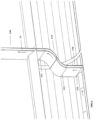
- FIG.3 provides a schematic illustration of how a water drainage device according to the embodiment with a curved middle part may be used in a pipe. It is clear from the drawing that a water free region is created behind the pipe contacting section 12 and underneath the curved middle section 11.
- the upper part 100 and the lower part 120 comprise substantially planar surfaces that are arranged to face the direction of the flow of water.
- the fact that the upper and lower parts are provided in substantially planar shape will simplify the insertion of the device into a gap defined by the seams or joints of the pipe. If the middle section is curved the user may thread the device into the pipe through the gap defined by the pipe seams or joints.
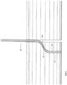
- FIG.4 A schematic illustration of this embodiment is provided by FIG.4 .
- Yet another exemplary embodiment provides a water drainage device where the distance, in a direction parallel to the water flow, between the upper end 111 and the lower end 112 of the middle part 110 is at least 10 cm.
- This particular embodiment ensures a safety distance to the main body when the device is used to e.g. enable welding in the pipe. That is, it ensures that there is a substantial distance between the main body and the welding spot.
- the safety distance, and thus the distance between the upper end 111 and the lower end 112 of the middle part 110 may of course be altered to fit the particular situation.
- All the disclosed embodiments may be provided as a uniformly constructed device, i.e. a device where all the parts, i.e. the first or upper part, the second or middle part and the third or pipe contacting part, are constructed from a single piece or molded or cast in single piece.
- a modular water drainage device One particular advantage is that the length and/or curvature of the middle part may be varied in order to create different sized regions underneath the curved middle part.
- the water drainage device is a modular water drainage device where the middle part 110 comprises a curved module that is detachably attached to the upper part 100 and the lower part 120.
- the water drainage device 1 can be fitted with different curved modules that provides different distances between the upper end 111 and the lower end 112. That is, different sized water free regions underneath the curved module may be obtained by using curved modules with different sizes and/or different curvatures.
- the curved module may be attached to the upper part and lower part with any suitable locking means, such as e.g. a clamp lock or a snap-fit lock. It is also possible to provide the curved module and the upper part/lower part with shapes that enables that one end of the curved module slides over a corresponding end of the upper part/lower part in such a way that they form an overlapping section which provides an interlocking mechanism.
- a similar modular water drainage device may be used to provide pipe contacting sections that are tailored to fit with different pipe profiles.
- An embodiment that allows for this is provided by a water drainage device where the pipe contacting section 12 is a detachable section whereby the water drainage device 1 can be provided with pipe contacting sections 12 having edges 12a that are tailored to different water pipe profiles.
- the modular pipe contacting section may be attached to the second or middle part with any suitable locking means, such as e.g. a clamp lock or a snap-fit lock. It is also possible to provide the pipe contacting section and the middle section/curved module with shapes that enables that one end of the pipe contacting section slides over a corresponding end of the curved section/module in such a way that they overlap and interlock which provides the locking means.
- a water drainage device where the main body 10 comprises attaching means for attaching the water drainage device 1 to the water pipe.
- attaching means for attaching the water drainage device 1 to the water pipe.
- the attaching means may for example be a clamp lock.
- Other attaching means are possible, such as snap-fit means.
- the device comprises a water drainage device 1 where the main body 10 comprises a second surface 11b that is arranged on the opposite side of the first surface 11a, with respect to the intended direction of the water flow in the pipe.
- the second surface comprises a heat resisting material or is covered with a heat resisting layer.
- the embodiment is schematically illustrated in FIG.5 , the layer is however not shown.
- This embodiment may advantageously be used to enable welding in the water free region created by the device. During use the second surface 11b will be closer to the welding spot, and the heat emerging from the welding flame will heat the second surface and the heat may possibly damage the surface. If, for example, the second surface comprises a plastic material it might melt, or at least degenerate, due to the substantial heat associated with welding. The proposed embodiment therefore provides additional protection against the heat from the welding flame.
- the second surface 11b that is arranged on the opposite side of the first surface 11a, with respect to the intended direction of the water flow in the pipe, may in one particular embodiment be comprised as a part of the main body 10 that is produced from a heat resistant material. Another possibility is however to provide the second surface 11b with a layer of a material with beneficial heat resistant characteristics.
- the water drainage device may in a particular embodiment be produced from a rather inexpensive but robust material, such as a plastic, where the second surface 11b has been provided with a heat resisting layer.
- a heat resisting layer might for example be a ceramic layer.
- Another suitable material characteristic is that the material used to produce the water drainage device, or the components thereof, e.g. the middle section or the pipe contacting section, is flexible.
- the flexibility of the device or the components may simplify the insertion of the device into a water pipe through a minor gap such as a pipe seam or joint.
- the device may comprise water removal means connected to the water outlet 12c and being adapted to remove water from the water pipe through the water transferring channel 13 extending through the main body 10 from the water inlet 12b to the water outlet 12c.
- the water removal means may be a water pump or a water suction device, such as a vacuum suction device.
- the water removal means are not necessarily part of the water drainage device, the water drainage device may instead comprise connection means for connecting the water outlet arranged in the main body with an external water removal means.
- the main body 10 of the water drainage device may be provided with a width dimension, defined by the extension or distance between the first surface 11a and a second surface 11b arranged on the opposite side of the first surface, with respect to intended direction of the water flow, that enables the device to be inserted into the water pipe through small gaps such as seams or joints in the water pipe.
- the width dimension may for example range between approximately 2 mm and 12 mm. Other dimensions are however possible and the choices may be made in light of the actual size of the gaps, pipe seams or joints.
- FIGs 6a-6d The various parts of the water drainage device are schematically illustrated in FIGs 6a-6d.
- FIG.6a illustrate the pipe contacting section 12 with a pipe contacting edge 12a that is adapted to lie flush with the profile of the inner surface of a pipe.
- FIG.6b illustrates the middle part, or middle section, 11 with a curved portion 15.
- FIG.6c provides a schematic illustration of the shape of the main body 10 of a water drainage device, with a non-curved middle section.
- FIG. 6d illustrates, schematically a water outlet provided with a nozzle that is adapted to be connected to a water removal means.
- the proposed water drainage device may be provided in module form, i.e. in a form where one or several parts can be assembled in order to obtain the water drainage device.
- the module parts may for example be a module having a shape that corresponds to the pipe contacting section 12 of the assembled water drainage device.
- An advantage obtained with such a module is that the size and shape of the module may be adapted to fit different sized pipes with different shape pipe profiles.
- the proposed technology also provides a pipe contacting module 12 to be fitted on a water drainage device 1 according to what has been described.
- the pipe contacting module 12 comprises an edge 12a with a shape adapted to lie essentially flush with the inner profile of a water pipe to prohibit water from flowing past the pipe contacting section 12 and a water inlet 12b adapted to be connected to the water draining channel 13 of the water drainage device 1.
- the pipe contacting module 12 may be provided with attaching means for attaching the module to the water drainage device main body, i.e. be attached to a midsection of the water drainage device, e.g. a curved section 11.
- the attaching means may be a clamp lock or a snap-fit, other detachable locking mechanisms may however be used.
- Another particular module corresponds to the second or middle part 110 of the earlier described water drainage device.
- One advantage obtained with a detachable module corresponding to the second or middle part is that the curvature and size of such a module may be tailored for the particular application.
- Such a large region may for example be beneficial if the user intends to weld in the vicinity of the water free region. By distancing the water flow from the welding spot any cooling influence on the welding flame, from the water, may be reduced.
- the proposed technology provides a curved module adapted to be attached to a water drainage device 1 according to what has been described, the curved module comprises a first end, or an upper end 111, adapted to be attached to the first or upper part of the water drainage device and a second end, or lower end, 112 adapted to be attached to the third or lower part 120 of the water drainage device.
- the curved module should enclose a water transferring channel that connects to a corresponding water transferring channel in the third, or lower part, 120 that is, a water transferring channel in the pipe contacting section or module, and also to a water transferring channel arranged in the first or upper part 100 of the water drainage device in order to be able to remove the water from the pipe.
- the first or upper part 100 of the water drainage device also comprises, in this embodiment, the water outlet connecting to a water removal means.
- the main body 10 of the water drainage device describe in any of the earlier embodiments may be provided with an elliptically shaped cross-section, as viewed from an end of the device. Having a cross-section with such a tapered shape may simplify the insertion of the device into e.g. a pipe seam or joint.
- the main body may comprise illuminating means in the form of a light emitting diode arranged on the surface 11b.
- the light emitting diode may either be connected, by means of wires, to a power source, e.g. a battery, provided in the water drainage device or be connected to an external power source.
- the diode may be provided in an open ended cavity provided in the surface 11b where the cavity provides some protection to the diode against mechanical impacts, e.g.
- the wires connecting the diode to the power source could in one embodiment be built into the main body and in another embodiment be provided on the outside of the main body.
- the wires may for example be provided on the surface 11b, possibly in recesses provided on the surface in order to protect the wires.
- the illuminating means may also be provided on any of the proposed modules, i.e. the curved module or the pipe contacting module described earlier.
- the invention also provides a use of a water drainage device 1 according to what has been describe earlier in order to obtain a water free region in a water pipe and thereby enabling welding in the water free region.
- a water drainage device may prove particularly beneficial for providing a water free region in order to enable welding work in the water free region created by the device.
- the proposed water drainage device may be inserted into an opened pipe seam or pipe joint in order to create a water free region. Maintenance work may then be performed in the water free region. The open pipe seam or pipe joint may then be welded together to close the pipe. Maintenance work can at a later stage be performed again by opening up the joint or seam and inserting the device.
Landscapes
- Engineering & Computer Science (AREA)
- General Engineering & Computer Science (AREA)
- Mechanical Engineering (AREA)
- Health & Medical Sciences (AREA)
- Life Sciences & Earth Sciences (AREA)
- Hydrology & Water Resources (AREA)
- Public Health (AREA)
- Water Supply & Treatment (AREA)
- Sink And Installation For Waste Water (AREA)
- Pipeline Systems (AREA)
Claims (8)
- Wasserableitungsvorrichtung, die dazu geeignet ist, in ein kreisförmiges Wasserrohr eingesetzt zu werden, wobei die Wasserableitungsvorrichtung einen Hauptkörper (10) umfasst, welcher umfasst:- eine erste Oberfläche (11a), die dazu geeignet ist, dem Strom von Wasser im kreisförmigen Wasserrohr zugekehrt zu sein;- eine Rohrkontaktsektion (12), die eine Kante (12a) mit einer Form aufweist, welche dazu geeignet ist, im Wesentlichen bündig mit dem Innenprofil des kreisförmigen Wasserrohrs zu liegen, um zu verhindern, dass Wasser an der Rohrkontaktsektion (12) vorbeiströmt;- einen Wassereinlass, der in der Rohrkontaktsektion (12) angeordnet ist und dazu geeignet ist, dem Wasserstrom im kreisförmigen Wasserrohr zugekehrt zu sein;- einen Wasserauslass (12c), der dazu geeignet ist, mit einem Wasserentfernungsmittel verbunden zu sein;- ein erstes Teil (100), das mit einem ersten Ende (111) eines zweiten Teils (110) verbindet, wobei das zweite Teil (110) ferner ein zweites Ende (112) umfasst, das mit einem ersten Ende (121) eines dritten Teils (120) verbindet, welches die Rohrkontaktsektion (12) umfasst, wobei das zweite Teil (110) eine gekrümmte Form aufweist, wodurch das zweite Ende (112) des zweiten Teils (110) dazu geeignet ist, weiter stromaufwärts zum Wasserstrom als das erste Ende (111) nach dem Einsetzen der Wasserableitungsvorrichtung angeordnet zu sein; wobei das erste Teil (100) und das dritte Teil (120) im Wesentlichen plane Oberflächen umfassen, die dazu angeordnet sind, der Richtung des Stroms von Wasser zugekehrt zu sein; wobei das erste Teil (100) und das dritte Teil (120) dazu geeignet sind, dem Strom von Wasser im kreisförmigen Wasserrohr zugekehrt zu sein, und ihre Längenausdehnungen dazu geeignet sind, im Wesentlichen senkrecht zum Wasserstrom und/oder zum kreisförmigen Wasserrohr angeordnet zu sein;- einen Wasserableitungskanal (13), der durch den Hauptkörper (10) vom Wassereinlass zum Wasserauslass (12c) verläuft und zum Ermöglichen geeignet ist, dass Wasser aus dem kreisförmigen Rohr abgeleitet wird, wobei der Hauptkörper (10) ferner eine Breitenabmessung zwischen der ersten Oberfläche (11a) und einer zweiten Oberfläche (11b), welche auf der gegenüberliegenden Seite der ersten Oberfläche (11a) angeordnet ist, bezüglich der beabsichtigten Richtung des Wasserstroms umfasst, die es ermöglicht, dass die Vorrichtung durch offene Fugen oder offene Verbindungsstellen im kreisförmigen Wasserrohr in das kreisförmige Wasserrohr eingesetzt wird.
- Wasserableitungsvorrichtung nach Anspruch 1, wobei der Abstand, in einer parallel zum Wasserstrom verlaufenden Richtung, zwischen dem ersten Ende (111) und dem zweiten Ende (112) des zweiten Teils (110) zumindest 10 cm beträgt.
- Wasserableitungsvorrichtung nach einem der Ansprüche 1 oder 2, wobei das zweite Teil (110) ein gekrümmtes Modul (15) umfasst, das dazu geeignet ist, abnehmbar am ersten Teil (100) und am dritten Teil (120) angebracht zu sein, wodurch die Wasserableitungsvorrichtung (1) mit verschiedenen gekrümmten Modulen (15) ausgestattet werden kann, die verschiedene Abstände zwischen dem ersten Ende (111) und dem zweiten Ende (112) vorsehen.
- Wasserableitungsvorrichtung nach einem der Ansprüche 1 bis 3, wobei die Rohrkontaktsektion (12) eine abnehmbare Sektion ist, wodurch die Wasserableitungsvorrichtung (1) mit Rohrkontaktsektionen mit Kanten (12a) versehen werden kann, welche auf kreisförmige Wasserrohrprofile verschiedener Größe zugeschnitten sind.
- Wasserableitungsvorrichtung nach einem der Ansprüche 1 bis 4, wobei der Hauptkörper (10) Anbringungsmittel zum Anbringen der Wasserableitungsvorrichtung (1) am kreisförmigen Wasserrohr umfasst.
- Wasserableitungsvorrichtung nach einem der Ansprüche 1 bis 5, ferner umfassend Wasserentfernungsmittel, die mit dem Wasserauslass (12c) verbunden sind und dazu geeignet sind, Wasser aus dem kreisförmigen Wasserrohr durch den Wasserüberführungskanal (13), der durch den Hauptkörper (10) vom Wassereinlass zum Wasserauslass (12c) verläuft, zu entfernen.
- Wasserableitungsvorrichtung nach einem der Ansprüche 1 bis 6, wobei die Breitenabmessung zwischen ungefähr 2 mm und 12 mm liegt.
- Verwendung einer Wasserableitungsvorrichtung (1) nach einem der Ansprüche 1 bis 7 zum Erzielen eines wasserfreien Bereichs in einem kreisförmigen Wasserrohr und dadurch Ermöglichen von Schweißen im wasserfreien Bereich.
Applications Claiming Priority (2)
| Application Number | Priority Date | Filing Date | Title |
|---|---|---|---|
| SE1750829A SE541465C2 (en) | 2017-06-27 | 2017-06-27 | Device for draining or removing water from a water pipe |
| PCT/SE2018/050646 WO2019004899A1 (en) | 2017-06-27 | 2018-06-19 | DEVICE FOR DRAINING OR DRAINING WATER FROM A WATER PIPE |
Publications (4)
| Publication Number | Publication Date |
|---|---|
| EP3645928A1 EP3645928A1 (de) | 2020-05-06 |
| EP3645928A4 EP3645928A4 (de) | 2021-04-21 |
| EP3645928B1 true EP3645928B1 (de) | 2023-08-09 |
| EP3645928C0 EP3645928C0 (de) | 2023-08-09 |
Family
ID=64741795
Family Applications (1)
| Application Number | Title | Priority Date | Filing Date |
|---|---|---|---|
| EP18822981.9A Active EP3645928B1 (de) | 2017-06-27 | 2018-06-19 | Vorrichtung zum ableiten oder entfernen von wasser aus einem wasserrohr mit kreisförmigem querschnitt sowie ihre verwendung |
Country Status (5)
| Country | Link |
|---|---|
| US (1) | US20200200314A1 (de) |
| EP (1) | EP3645928B1 (de) |
| CN (1) | CN110998163A (de) |
| SE (1) | SE541465C2 (de) |
| WO (1) | WO2019004899A1 (de) |
Families Citing this family (1)
| Publication number | Priority date | Publication date | Assignee | Title |
|---|---|---|---|---|
| CN116772118A (zh) * | 2023-08-10 | 2023-09-19 | 新兴铸管股份有限公司 | 管道排水装置、长距离管道输水系统及方法 |
Citations (1)
| Publication number | Priority date | Publication date | Assignee | Title |
|---|---|---|---|---|
| GB2542209A (en) * | 2015-09-14 | 2017-03-15 | Hydro Int Plc | A nozzle for a vacuum pump or truck |
Family Cites Families (15)
| Publication number | Priority date | Publication date | Assignee | Title |
|---|---|---|---|---|
| FR2604079A1 (fr) * | 1986-09-24 | 1988-03-25 | Labbe Jean Pierre | Aspirateur domestique a suceur a double effet |
| SE460013B (sv) * | 1987-11-20 | 1989-09-04 | Adolf Gunnar Gustafson | Anordning foer att medelst undertryck avlaegsna partiklar, vaetskor etc.fraan ett underlag |
| US5435478A (en) * | 1991-08-05 | 1995-07-25 | Wood; J. W. | Welding apparatus and method |
| US5651393A (en) * | 1996-01-02 | 1997-07-29 | Danowski; Robert T. | Fluid diversion apparatus |
| AU2620897A (en) * | 1996-06-25 | 1998-01-15 | Kim Hill | Method and device for modifying fluid flow |
| KR19980028714U (ko) * | 1996-11-25 | 1998-08-05 | 이영서 | 진공청소기의 틈새이물질 제거구 |
| US6681796B2 (en) * | 2000-02-18 | 2004-01-27 | Lloyd Herbert King, Jr. | Drainage valve pipe tap assembly |
| CA2444466A1 (en) * | 2003-10-07 | 2005-04-07 | Waterfall, Inc. | Plumbing tool and method for repairing a pipe therewith |
| GB2444196B (en) * | 2003-10-08 | 2008-07-16 | Waterfall Inc | Plumbing tool and method for repairing a pipe therewith |
| US6820636B1 (en) * | 2003-12-12 | 2004-11-23 | Tai Kien | Plumbing tool |
| CN2731237Y (zh) * | 2004-11-12 | 2005-10-05 | 广东联塑科技实业有限公司 | 一种用于修补受损管道的管道修复装置 |
| CN2886285Y (zh) * | 2006-04-26 | 2007-04-04 | 河北奥翔格瑞工业技术有限公司 | 一种大口径管道试水用堵水器 |
| DE102008055043B4 (de) * | 2008-12-19 | 2013-04-25 | BSH Bosch und Siemens Hausgeräte GmbH | Multifunktionsdüse für Staubsauger |
| JP5426610B2 (ja) * | 2011-06-10 | 2014-02-26 | タイガースポリマー株式会社 | ホースアッセンブリの製造方法 |
| CN203718275U (zh) * | 2014-01-26 | 2014-07-16 | 杨红星 | 一种排水管道检查口用堵水装置 |
-
2017
- 2017-06-27 SE SE1750829A patent/SE541465C2/en not_active IP Right Cessation
-
2018
- 2018-06-19 US US16/620,780 patent/US20200200314A1/en not_active Abandoned
- 2018-06-19 WO PCT/SE2018/050646 patent/WO2019004899A1/en not_active Ceased
- 2018-06-19 CN CN201880042045.1A patent/CN110998163A/zh active Pending
- 2018-06-19 EP EP18822981.9A patent/EP3645928B1/de active Active
Patent Citations (1)
| Publication number | Priority date | Publication date | Assignee | Title |
|---|---|---|---|---|
| GB2542209A (en) * | 2015-09-14 | 2017-03-15 | Hydro Int Plc | A nozzle for a vacuum pump or truck |
Also Published As
| Publication number | Publication date |
|---|---|
| EP3645928A4 (de) | 2021-04-21 |
| US20200200314A1 (en) | 2020-06-25 |
| EP3645928A1 (de) | 2020-05-06 |
| EP3645928C0 (de) | 2023-08-09 |
| SE1750829A1 (en) | 2018-12-28 |
| SE541465C2 (en) | 2019-10-08 |
| WO2019004899A1 (en) | 2019-01-03 |
| CN110998163A (zh) | 2020-04-10 |
Similar Documents
| Publication | Publication Date | Title |
|---|---|---|
| BR112013007784A2 (pt) | Elemento filtrante e sistema de filtro | |
| EP3645928B1 (de) | Vorrichtung zum ableiten oder entfernen von wasser aus einem wasserrohr mit kreisförmigem querschnitt sowie ihre verwendung | |
| ES2274006T3 (es) | Valvula de compuerta. | |
| MX2012006505A (es) | Sistema de manejo de liquido escalable modular. | |
| BR112014021150B1 (pt) | arranjo de filtro de ar | |
| KR101720249B1 (ko) | 유체 확인용 사이트 글라스 | |
| JP6405272B2 (ja) | 弁装置 | |
| JP6348035B2 (ja) | 排水ますおよびそれを備えた排水システム | |
| KR102252710B1 (ko) | 욕실 청소용 스프레이 건 | |
| CN203050834U (zh) | 工程机械及其发动机的油底壳 | |
| KR100943937B1 (ko) | 상수도관 내의 불순물 제거장치 | |
| JP5763601B2 (ja) | 止水装置 | |
| KR20170035448A (ko) | 관로 준설용 노즐 | |
| KR20140092463A (ko) | 비굴착식 상하수도 보수용 매니폴드 장치 | |
| KR100793905B1 (ko) | 하수,오수,폐수관용 세정장치 | |
| CA2051150C (en) | Removable flushing system for machine tool coolant return system flumes | |
| JP7378710B2 (ja) | 排水吸引回収装置 | |
| JP4519580B2 (ja) | 既設流体管の不断水流路形成装置 | |
| CN103821116A (zh) | 一种电站补气防水装置 | |
| JP6422630B2 (ja) | 弁装置を有する分岐管 | |
| JP5832929B2 (ja) | 流体管分岐装置及び流体分岐方法 | |
| KR100854699B1 (ko) | 상수관 터널 갱생 자동화장치용 분사장치. | |
| JP4166557B2 (ja) | ディスポーザ用掃除口付き排水トラップ | |
| JP4616600B2 (ja) | 既設流体管の不断水流路形成装置 | |
| JPH0340890Y2 (de) |
Legal Events
| Date | Code | Title | Description |
|---|---|---|---|
| STAA | Information on the status of an ep patent application or granted ep patent |
Free format text: STATUS: THE INTERNATIONAL PUBLICATION HAS BEEN MADE |
|
| PUAI | Public reference made under article 153(3) epc to a published international application that has entered the european phase |
Free format text: ORIGINAL CODE: 0009012 |
|
| STAA | Information on the status of an ep patent application or granted ep patent |
Free format text: STATUS: REQUEST FOR EXAMINATION WAS MADE |
|
| 17P | Request for examination filed |
Effective date: 20200127 |
|
| AK | Designated contracting states |
Kind code of ref document: A1 Designated state(s): AL AT BE BG CH CY CZ DE DK EE ES FI FR GB GR HR HU IE IS IT LI LT LU LV MC MK MT NL NO PL PT RO RS SE SI SK SM TR |
|
| AX | Request for extension of the european patent |
Extension state: BA ME |
|
| DAV | Request for validation of the european patent (deleted) | ||
| DAX | Request for extension of the european patent (deleted) | ||
| A4 | Supplementary search report drawn up and despatched |
Effective date: 20210319 |
|
| RIC1 | Information provided on ipc code assigned before grant |
Ipc: F16L 55/07 20060101AFI20210315BHEP Ipc: E03B 7/08 20060101ALI20210315BHEP |
|
| GRAP | Despatch of communication of intention to grant a patent |
Free format text: ORIGINAL CODE: EPIDOSNIGR1 |
|
| STAA | Information on the status of an ep patent application or granted ep patent |
Free format text: STATUS: GRANT OF PATENT IS INTENDED |
|
| INTG | Intention to grant announced |
Effective date: 20230310 |
|
| GRAS | Grant fee paid |
Free format text: ORIGINAL CODE: EPIDOSNIGR3 |
|
| GRAA | (expected) grant |
Free format text: ORIGINAL CODE: 0009210 |
|
| STAA | Information on the status of an ep patent application or granted ep patent |
Free format text: STATUS: THE PATENT HAS BEEN GRANTED |
|
| AK | Designated contracting states |
Kind code of ref document: B1 Designated state(s): AL AT BE BG CH CY CZ DE DK EE ES FI FR GB GR HR HU IE IS IT LI LT LU LV MC MK MT NL NO PL PT RO RS SE SI SK SM TR |
|
| REG | Reference to a national code |
Ref country code: GB Ref legal event code: FG4D |
|
| REG | Reference to a national code |
Ref country code: CH Ref legal event code: EP |
|
| REG | Reference to a national code |
Ref country code: IE Ref legal event code: FG4D |
|
| REG | Reference to a national code |
Ref country code: DE Ref legal event code: R096 Ref document number: 602018055136 Country of ref document: DE |
|
| U01 | Request for unitary effect filed |
Effective date: 20230906 |
|
| U07 | Unitary effect registered |
Designated state(s): AT BE BG DE DK EE FI FR IT LT LU LV MT NL PT SE SI Effective date: 20230913 |
|
| REG | Reference to a national code |
Ref country code: NO Ref legal event code: T2 Effective date: 20230809 |
|
| PG25 | Lapsed in a contracting state [announced via postgrant information from national office to epo] |
Ref country code: GR Free format text: LAPSE BECAUSE OF FAILURE TO SUBMIT A TRANSLATION OF THE DESCRIPTION OR TO PAY THE FEE WITHIN THE PRESCRIBED TIME-LIMIT Effective date: 20231110 |
|
| PG25 | Lapsed in a contracting state [announced via postgrant information from national office to epo] |
Ref country code: IS Free format text: LAPSE BECAUSE OF FAILURE TO SUBMIT A TRANSLATION OF THE DESCRIPTION OR TO PAY THE FEE WITHIN THE PRESCRIBED TIME-LIMIT Effective date: 20231209 |
|
| PG25 | Lapsed in a contracting state [announced via postgrant information from national office to epo] |
Ref country code: RS Free format text: LAPSE BECAUSE OF FAILURE TO SUBMIT A TRANSLATION OF THE DESCRIPTION OR TO PAY THE FEE WITHIN THE PRESCRIBED TIME-LIMIT Effective date: 20230809 Ref country code: IS Free format text: LAPSE BECAUSE OF FAILURE TO SUBMIT A TRANSLATION OF THE DESCRIPTION OR TO PAY THE FEE WITHIN THE PRESCRIBED TIME-LIMIT Effective date: 20231209 Ref country code: HR Free format text: LAPSE BECAUSE OF FAILURE TO SUBMIT A TRANSLATION OF THE DESCRIPTION OR TO PAY THE FEE WITHIN THE PRESCRIBED TIME-LIMIT Effective date: 20230809 Ref country code: GR Free format text: LAPSE BECAUSE OF FAILURE TO SUBMIT A TRANSLATION OF THE DESCRIPTION OR TO PAY THE FEE WITHIN THE PRESCRIBED TIME-LIMIT Effective date: 20231110 |
|
| PG25 | Lapsed in a contracting state [announced via postgrant information from national office to epo] |
Ref country code: PL Free format text: LAPSE BECAUSE OF FAILURE TO SUBMIT A TRANSLATION OF THE DESCRIPTION OR TO PAY THE FEE WITHIN THE PRESCRIBED TIME-LIMIT Effective date: 20230809 |
|
| PG25 | Lapsed in a contracting state [announced via postgrant information from national office to epo] |
Ref country code: ES Free format text: LAPSE BECAUSE OF FAILURE TO SUBMIT A TRANSLATION OF THE DESCRIPTION OR TO PAY THE FEE WITHIN THE PRESCRIBED TIME-LIMIT Effective date: 20230809 |
|
| PG25 | Lapsed in a contracting state [announced via postgrant information from national office to epo] |
Ref country code: SM Free format text: LAPSE BECAUSE OF FAILURE TO SUBMIT A TRANSLATION OF THE DESCRIPTION OR TO PAY THE FEE WITHIN THE PRESCRIBED TIME-LIMIT Effective date: 20230809 Ref country code: RO Free format text: LAPSE BECAUSE OF FAILURE TO SUBMIT A TRANSLATION OF THE DESCRIPTION OR TO PAY THE FEE WITHIN THE PRESCRIBED TIME-LIMIT Effective date: 20230809 Ref country code: ES Free format text: LAPSE BECAUSE OF FAILURE TO SUBMIT A TRANSLATION OF THE DESCRIPTION OR TO PAY THE FEE WITHIN THE PRESCRIBED TIME-LIMIT Effective date: 20230809 Ref country code: CZ Free format text: LAPSE BECAUSE OF FAILURE TO SUBMIT A TRANSLATION OF THE DESCRIPTION OR TO PAY THE FEE WITHIN THE PRESCRIBED TIME-LIMIT Effective date: 20230809 Ref country code: SK Free format text: LAPSE BECAUSE OF FAILURE TO SUBMIT A TRANSLATION OF THE DESCRIPTION OR TO PAY THE FEE WITHIN THE PRESCRIBED TIME-LIMIT Effective date: 20230809 |
|
| REG | Reference to a national code |
Ref country code: DE Ref legal event code: R097 Ref document number: 602018055136 Country of ref document: DE |
|
| PLBE | No opposition filed within time limit |
Free format text: ORIGINAL CODE: 0009261 |
|
| STAA | Information on the status of an ep patent application or granted ep patent |
Free format text: STATUS: NO OPPOSITION FILED WITHIN TIME LIMIT |
|
| 26N | No opposition filed |
Effective date: 20240513 |
|
| U21 | Renewal fee for the european patent with unitary effect paid with additional fee |
Year of fee payment: 7 Effective date: 20241219 |
|
| PG25 | Lapsed in a contracting state [announced via postgrant information from national office to epo] |
Ref country code: MC Free format text: LAPSE BECAUSE OF FAILURE TO SUBMIT A TRANSLATION OF THE DESCRIPTION OR TO PAY THE FEE WITHIN THE PRESCRIBED TIME-LIMIT Effective date: 20230809 |
|
| REG | Reference to a national code |
Ref country code: CH Ref legal event code: PL |
|
| PG25 | Lapsed in a contracting state [announced via postgrant information from national office to epo] |
Ref country code: IE Free format text: LAPSE BECAUSE OF NON-PAYMENT OF DUE FEES Effective date: 20240619 |
|
| PG25 | Lapsed in a contracting state [announced via postgrant information from national office to epo] |
Ref country code: CH Free format text: LAPSE BECAUSE OF NON-PAYMENT OF DUE FEES Effective date: 20240630 |
|
| PGFP | Annual fee paid to national office [announced via postgrant information from national office to epo] |
Ref country code: GB Payment date: 20250630 Year of fee payment: 8 |
|
| U20 | Renewal fee for the european patent with unitary effect paid |
Year of fee payment: 8 Effective date: 20250630 |
|
| PGFP | Annual fee paid to national office [announced via postgrant information from national office to epo] |
Ref country code: NO Payment date: 20250701 Year of fee payment: 8 |
|
| PG25 | Lapsed in a contracting state [announced via postgrant information from national office to epo] |
Ref country code: CY Free format text: LAPSE BECAUSE OF FAILURE TO SUBMIT A TRANSLATION OF THE DESCRIPTION OR TO PAY THE FEE WITHIN THE PRESCRIBED TIME-LIMIT; INVALID AB INITIO Effective date: 20180619 |
|
| PG25 | Lapsed in a contracting state [announced via postgrant information from national office to epo] |
Ref country code: HU Free format text: LAPSE BECAUSE OF FAILURE TO SUBMIT A TRANSLATION OF THE DESCRIPTION OR TO PAY THE FEE WITHIN THE PRESCRIBED TIME-LIMIT; INVALID AB INITIO Effective date: 20180619 |