EP3645394B1 - Wandelbare bordküche in flugzeugen - Google Patents
Wandelbare bordküche in flugzeugen Download PDFInfo
- Publication number
- EP3645394B1 EP3645394B1 EP18735234.9A EP18735234A EP3645394B1 EP 3645394 B1 EP3645394 B1 EP 3645394B1 EP 18735234 A EP18735234 A EP 18735234A EP 3645394 B1 EP3645394 B1 EP 3645394B1
- Authority
- EP
- European Patent Office
- Prior art keywords
- panel
- side wall
- configuration
- accordance
- board facility
- Prior art date
- Legal status (The legal status is an assumption and is not a legal conclusion. Google has not performed a legal analysis and makes no representation as to the accuracy of the status listed.)
- Active
Links
Images



Classifications
-
- B—PERFORMING OPERATIONS; TRANSPORTING
- B64—AIRCRAFT; AVIATION; COSMONAUTICS
- B64D—EQUIPMENT FOR FITTING IN OR TO AIRCRAFT; FLIGHT SUITS; PARACHUTES; ARRANGEMENT OR MOUNTING OF POWER PLANTS OR PROPULSION TRANSMISSIONS IN AIRCRAFT
- B64D11/00—Passenger or crew accommodation; Flight-deck installations not otherwise provided for
- B64D11/04—Galleys
-
- F—MECHANICAL ENGINEERING; LIGHTING; HEATING; WEAPONS; BLASTING
- F25—REFRIGERATION OR COOLING; COMBINED HEATING AND REFRIGERATION SYSTEMS; HEAT PUMP SYSTEMS; MANUFACTURE OR STORAGE OF ICE; LIQUEFACTION SOLIDIFICATION OF GASES
- F25D—REFRIGERATORS; COLD ROOMS; ICE-BOXES; COOLING OR FREEZING APPARATUS NOT OTHERWISE PROVIDED FOR
- F25D23/00—General constructional features
- F25D23/02—Doors; Covers
- F25D23/021—Sliding doors
-
- F—MECHANICAL ENGINEERING; LIGHTING; HEATING; WEAPONS; BLASTING
- F25—REFRIGERATION OR COOLING; COMBINED HEATING AND REFRIGERATION SYSTEMS; HEAT PUMP SYSTEMS; MANUFACTURE OR STORAGE OF ICE; LIQUEFACTION SOLIDIFICATION OF GASES
- F25D—REFRIGERATORS; COLD ROOMS; ICE-BOXES; COOLING OR FREEZING APPARATUS NOT OTHERWISE PROVIDED FOR
- F25D23/00—General constructional features
- F25D23/02—Doors; Covers
- F25D23/025—Secondary closures
-
- F—MECHANICAL ENGINEERING; LIGHTING; HEATING; WEAPONS; BLASTING
- F25—REFRIGERATION OR COOLING; COMBINED HEATING AND REFRIGERATION SYSTEMS; HEAT PUMP SYSTEMS; MANUFACTURE OR STORAGE OF ICE; LIQUEFACTION SOLIDIFICATION OF GASES
- F25D—REFRIGERATORS; COLD ROOMS; ICE-BOXES; COOLING OR FREEZING APPARATUS NOT OTHERWISE PROVIDED FOR
- F25D23/00—General constructional features
- F25D23/02—Doors; Covers
- F25D23/028—Details
-
- Y—GENERAL TAGGING OF NEW TECHNOLOGICAL DEVELOPMENTS; GENERAL TAGGING OF CROSS-SECTIONAL TECHNOLOGIES SPANNING OVER SEVERAL SECTIONS OF THE IPC; TECHNICAL SUBJECTS COVERED BY FORMER USPC CROSS-REFERENCE ART COLLECTIONS [XRACs] AND DIGESTS
- Y02—TECHNOLOGIES OR APPLICATIONS FOR MITIGATION OR ADAPTATION AGAINST CLIMATE CHANGE
- Y02T—CLIMATE CHANGE MITIGATION TECHNOLOGIES RELATED TO TRANSPORTATION
- Y02T50/00—Aeronautics or air transport
- Y02T50/40—Weight reduction
Definitions
- the invention relates to an on-board device for a means of transport, preferably a galley or bar for an aircraft, which has at least one visible side wall and at least one panel for partially or completely concealing a working area of the on-board device.
- US2001/0050519A1 relates to a galley unit for an aircraft with a supply mechanism provided on at least one wall surface of a box body and a cover body whose outer wall surfaces consist of at least one special fireproof material.
- US2008/0116773A1 relates to a device for receiving objects comprising at least one panel with at least one outer edge provided with a rim to form a shock-absorbing edge.
- USS6761332B1 a galley system having a first structure, a second structure and a crew aisle between the first structure and the second structure.
- the galley system additionally includes a set of doors connected to the first structure and the second structure to conceal the crew aisle from the view of boarding passengers when the doors are in a closed position.
- galleys in aircraft are varied. For example, it may be desirable to conceal the galley work area during boarding, especially if the galley is located in a place in the aircraft that passengers cross. During the flight, on the other hand, the crew needs the galley work area to prepare and carry out the service. Roller blinds, for example, are used to conceal the work area.
- Visible side walls of the galley can be used for various functions, such as welcoming or informing passengers through electronic or printed displays, graphics, signs, logos or symbols.
- the side walls can have pockets or shelves for storing magazines, drinks, etc.
- the use of such a side wall is limited because it is stationary and not convertible.
- the side wall has no function, or it only performs one of the functions mentioned above.
- the blind that conceals the work area of the galley is also designed for only one function.
- the blind can be lowered when boarding and disembarking, but it must be rolled up during the flight, so in this case, for example during service, it has no function.
- An object of the invention is to provide an improved on-board facility for a means of transport, preferably a galley or bar for an aircraft, in particular to improve the functionality of such an on-board facility.
- the on-board equipment according to the invention is used in means of transport, for example airplanes, buses or ships. It is particularly useful when there is little space available.
- the on-board equipment is a galley or a bar for an airplane, because the synergistic combination of several functions by a single technical means is extremely useful, especially in air traffic, in order to use the limited space effectively and save weight.
- the on-board equipment has at least one visible side wall and at least one panel for partially or completely concealing a working area of the on-board equipment.
- the side wall is the outer wall or a section of the outer wall of a housing or an external panel of the on-board equipment.
- the term "side wall” does not refer to a specific side of the on-board equipment, although it particularly preferably includes a section of the on-board equipment that is visible from the outside, for example facing an aircraft door and thus visible to passengers during boarding.
- the panel is designed to conceal the work area that the crew uses, for example, to prepare or carry out a service and for this purpose may have technical equipment (oven, microwave, refrigerator, etc.), work surfaces, shelves and the like. If the work area is covered or hidden by the panel, the panel in this configuration is not conceptually part of the "side wall".
- the cover can be adjusted between at least two configurations, wherein the cover forms or covers at least part of the side wall in a first configuration and partially or completely covers the work area in a second configuration.
- the cover performs at least two functions: a) covering the work area of the on-board device; b) a side wall function.
- the cladding is usually of no use when the work area is exposed, for example when preparing and carrying out the service, in this case according to the invention it takes on the function of the side wall.
- the side wall of the on-board equipment is thus convertible and can be used in at least two ways.
- the side wall and the cladding thus work together synergistically to create a convertible side wall essentially without any additional technical means and at the same time ensure that the work area is concealed if desired.
- the expanded functionality of the on-board equipment does not require more space or more weight.
- the panel has an inner side which is visible in the first configuration and faces the work area in the second configuration, so that in the latter case it is not visible from a position outside the on-board equipment.
- a design, texture or functionality of the side wall such as pockets or holders for drinks, magazines, etc.
- visible and accessible in the first configuration can be completely hidden in the second configuration, i.e. when facing the work area.
- Such a structure can be achieved by the panel being a pivotally mounted door, which is preferably pivotable by approximately 270° about a pivot axis.
- the two configurations are preferably formed at the end positions of the achievable pivot amplitude.
- the door-like panel can thus assume a closed state (second configuration), in which it covers the work area, and an open state (first configuration), in which it at least partially forms the side wall.
- the convertibility of the side wall and the reconfiguration of the panel can be realized in a technically particularly simple manner according to this preferred embodiment.
- the on-board device has two panels, each of which partially conceals the work area, whereby the two panels can be designed symmetrically. In this way, a large/wide access to the work area can be ensured compared to the side wall. The space required for reconfiguration can also be minimized by using two or more panels.
- exactly two panels are provided, which, like two double doors, are symmetrically constructed and pivotably mounted.
- the on-board equipment can have a further visible side wall, with the two panels each being adjustable between the two configurations defined above.
- the pivotability of the panel(s) is preferably achieved around one axis of rotation.
- the panel(s) can be set up to be adjustable along other and/or further degrees of freedom.
- the panel(s) can thus be pivotable about further pivot points and/or axes of rotation and/or be mounted so that they can be moved.
- the on-board device can be equipped with technical means (latch, hook/eyelet, snap fastener, magnet, lock, etc.) for fastening and/or locking the panel(s) in the first and/or second configuration.
- the side wall in the first and second configurations provides different service functions, the service functions comprising, for example: displays, such as graphics, signs, logos or symbols; and/or holders, such as shelves or pockets, for providing or displaying magazines, drinks and/or other goods.
- the service functions comprising, for example: displays, such as graphics, signs, logos or symbols; and/or holders, such as shelves or pockets, for providing or displaying magazines, drinks and/or other goods.
- the side wall has a recess for receiving the cladding in the first configuration.
- the dimension of the recess corresponds to the dimension of the associated cladding.
- the recess is preferably dimensioned such that the cladding in the first configuration is received in it in such a way that the most homogeneous image of the visible side wall is obtained.
- the depth the recess must be dimensioned such that an approximately flat overall surface is formed, ie that the outward-facing surface of the cladding and the adjoining surface sections of the remaining side wall are essentially stepless.
- the or a panel is constructed from a plurality of parts that can be pivoted and/or moved relative to one another.
- the panel (similarly a plurality of panels) can have a main part and an extension, wherein the extension for the first configuration can be stowed in or on the main part in such a way that the panel fits into the recess.
- the total area of the cover can be modified, in particular enlarged for the second configuration.
- the embodiment is particularly useful when the width of the on-board equipment is greater than twice its depth.
- the extensions allow the two panels in the second configuration to be enlarged in such a way that the work area is essentially completely concealed.
- the extensions When changing to the first configuration, the extensions are stowed in or on the main part. This can be achieved by pushing the extension into a gap in the associated main part.
- the extension may be guided so as to be displaceable on the inner surface or outer surface of the main part, or the extension may be mounted so as to be pivotable relative to the main part.
- the cladding is mounted so that it can move parallel to the associated side wall.
- the cladding can be provided so that it can move in addition to or as an alternative to any pivoting.
- the on-board equipment preferably has a compartment that is accessible from the side wall and/or from the work area.
- the compartment can be set up as a cooling compartment, in which case the on-board equipment has means for cooling the compartment.
- the compartment is preferably accessible via one or more external doors from the side wall and/or one or more internal doors from the work area. In this way, the compartment is accessible to passengers in the second configuration (boarding state), for example from the aisle via the external door(s), which means that service can be offered even when the on-board equipment is not occupied by the crew.
- the crew for fill and/or operate the compartment, it is alternatively or additionally accessible via the internal door(s).
- access to the compartment via the internal door(s) is only possible in the service state, i.e. with the cover open, i.e. the internal door(s) are preferably set up in this case so that they can only be opened in the first configuration.
- the height of the panel(s) does not have to, but may, correspond to the height of the on-board equipment. It is preferably the same as the height of the work area or the height of the on-board equipment, but it may have a greater or reduced height, depending on the intended functionality and desired design.
- the invention is particularly preferably used in galleys or bars in aircraft, the invention can also be applied in other means of transport, such as buses or ships, as well as other service facilities.
- the Figures 1a, 1b and 1c show schematically the basic structure of an on-board facility 1 according to an embodiment.
- the on-board facility 1 is preferably a galley in an aircraft, but it can also be another facility, in particular a service facility, for example a bar.
- the Figures 1a, 1b and 1c Each cross-sectional view shows different configurations, allowing different application or usage states to be realized.
- the on-board device 1 has two visible side walls 10 and two symmetrically constructed and rotatably mounted facings 11.
- the facings 11 are rotatably mounted about a rotation axis 12, whereby they can be opened and closed like wing doors, as can be seen from a comparison of the Figures 1a and 1b emerges.
- the configuration of the Figure 1a be referred to as the "boarding state” or "second configuration".
- the outer side 10a of the side wall 10 is visible and can fulfill a desired service function, for example displaying information, welcoming, holding magazines or drinks, etc.
- the panels 11 conceal at the same time, a work area A of the on-board facility 1, which serves the crew, for example, to prepare and/or carry out a service and for this purpose can have technical equipment (oven, microwave, refrigerator, etc.), work surfaces, shelves and the like.
- the first configuration can be used when passengers get on and off, but it can also be used as a special configuration, for example to allow self-service when the on-board facility 1 is not occupied.
- the pivot bearings of the facings 11 are designed so that the facings 11 can each be rotated by 270°. In this way, a configuration can be realized, shown in the Figure 1c , in which the facings 11 each run parallel to the associated side wall 10 and in this sense form part of it. This configuration is referred to as the "service state" or "first configuration".
- the veneers 11 are each pivotably mounted about (exactly) one axis 12, they can also be pivotably mounted about several axes and/or translationally mounted.
- the side wall 10 In the service state, the side wall 10 - more precisely, its visible side - is formed completely or at least partially by the inner side 11i of the facing 11.
- the side walls 10 can have recesses 13 which accommodate the facings 11 in the service state, so that they form an approximately flat surface together with the other side wall sections.
- the specific design of the service state also the boarding state
- the facings 11 take on two functions due to their ability to pivot by 270°: a) concealing the work area A in the boarding state; b) a side wall function in the service state.
- the side walls 10 can thus be used in two ways.
- both side walls 10 do not have to have a service function (display, holder for magazines, drinks, etc.).
- a service function display, holder for magazines, drinks, etc.
- the associated panel 11 can be constructed in a different way, for example displaceable and/or pivotable by 90° to 180°.
- the pivoting of the facings 11 is realized around a rotation axis 12.
- the facings 11 can be adjusted along other and/or further degrees of freedom.
- the facings 11 can be pivoted around further pivot points and/or rotation axes and/or can be mounted so that they can be moved (see embodiment of the Figures 5a and 5b ).
- the on-board equipment can be equipped with technical means (latch, hook/eyelet, snap fastener, magnet, lock, etc.) for fastening and/or locking the panels 11 in the boarding state and/or service state, in particular to secure the panels 11 during take-off, landing or turbulence in the air.
- technical means latch, hook/eyelet, snap fastener, magnet, lock, etc.
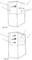
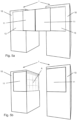
- FIGS. 2a and 2b are three-dimensional schematic views showing an exemplary functional design of the boarding state and the Service status of the on-board equipment 1.
- the two configurations differ in the design of the visible side wall 10. Specifically, different logos are displayed.
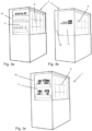
- the Figures 3a, 3b and 3c are three-dimensional schematic views showing various functional configurations of the service state of the on-board equipment 1.
- the inner sides 11i of the panels 11, which at least partially form the side wall 10 in the service state, can be equipped with storage compartments (pockets, shelves, compartments, etc.) for magazines (cf. Figure 3c ), drinks or other goods (cf. Figure 3a ).
- the height of the door-like panels 11 does not have to correspond to the height of the on-board equipment 1. Rather, it can correspond to the height of the work area A, have a greater or reduced height, depending on the intended functionality and desired design.
- the dimensions of the recesses 13 are also variable, or they can be omitted if necessary. Preferably, both the depth and the length of the recesses 13 correspond to the panels 11 to be accommodated therein.
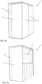
- FIGS. 3d and 3e show an embodiment in which the cladding 11 spans the entire or substantially entire height of the on-board device 1.
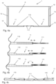
- the Figures 4a, 4b and 4c show schematically the basic structure of an on-board device 1 according to a further embodiment.
- the embodiment shown therein differs from the above embodiments in that the facings 11 are each constructed in several parts.
- the facings 11 each have a main part 110 and an extension 111 that can be pivoted and/or moved relative to it.
- a Such a multi-part design is particularly useful in the case of two symmetrical panels 11 when the width of the on-board equipment 1 is greater than twice its depth.
- the extensions 111 allow the panels 11 to be enlarged in the boarding state so that the working area A is essentially completely concealed.
- the extension 111 When changing to the first configuration, the extension 111 is stored in or on the main part 110. This can be achieved by inserting the extension 111 into a gap in the corresponding main part 110, see the upper variant of the Figure 4b Alternatively, the extension 111 can be guided on the inner surface or outer surface of the main part 110 and can be moved, see middle variant of the Figure 4b , or the extension 111 can be pivoted relative to the main part 110, see lower variant of the Figure 4b and Figure 4c . In the variant of the Figure 4c In the variant of the Figure 4c In the unfolded state of the extension(s) 111, a substantially flat visible outer surface of the cladding(s) 11 is achieved.
- the Figures 5a and 5b are three-dimensional schematic views of an on-board device 1 according to a further embodiment.
- the panels 11 are arranged to be movable parallel to the associated side walls 10 in addition to or as an alternative to pivoting.
- the paneling of the working area A takes place indirectly, as in the Figure 5a
- a configuration according to the Figure 5a in which the area between the two on-board devices 1 is at least partially separated, whereby a space of greater privacy can be created, for example for the crew.
- FIGS. 6a to 6c are three-dimensional schematic views showing further functional embodiments of the second configuration of the on-board device 1
- the work area A is closed off by the panels 11, which means that service can be provided even when the on-board facility is not occupied by the crew.
- a bar area with shelves for drinks and glasses can be accessible in the recess 13 of the side wall 10, as in the Figure 6a
- the bar area is covered or closed in the service state by the corresponding panel 11, which increases the functionality compared to the variant of the Figure 3a is in some ways reversed.
- the Figure 6b shows an embodiment in which pockets 14, for example for storing magazines, are provided in the recess 13 of the side wall 10.
- the outer sides of the panels 11 can also be equipped with pockets 14.
- the pockets 14 are preferably flexible, for example foldable or made of a material, so that when in service, they hardly require any storage space, hidden by the panels 11.
- FIGS. 6c , 7a and 7b show an embodiment in which a compartment 15, preferably designed as a cooling compartment, is provided in the recess 13 of a side wall 10.
- the compartment 15 is closed off by one or more external doors 15a ( Figure 7a ) and/or one or more interior doors 15b ( Figure 7b ) can be closed and opened.
- the compartment 15 is accessible to the passengers in the second configuration (boarding state), for example from the aisle via the outer door(s) 15a, as shown in the sectional view of the Figure 7a
- this is alternatively or additionally accessible via the inner door(s) 15b, as shown in the sectional view of the Figure 7b
- access to the compartment 15 via the inner door(s) 15b is only possible in the service state, ie when the cover 11 is open.
Landscapes
- Engineering & Computer Science (AREA)
- Thermal Sciences (AREA)
- Chemical & Material Sciences (AREA)
- Combustion & Propulsion (AREA)
- Physics & Mathematics (AREA)
- Mechanical Engineering (AREA)
- General Engineering & Computer Science (AREA)
- Aviation & Aerospace Engineering (AREA)
- Cabinets, Racks, Or The Like Of Rigid Construction (AREA)
- Passenger Equipment (AREA)
- Refrigerator Housings (AREA)
- Devices That Are Associated With Refrigeration Equipment (AREA)
- Vehicle Waterproofing, Decoration, And Sanitation Devices (AREA)
Description
- Die Erfindung betrifft eine Bordeinrichtung für ein Verkehrsmittel, vorzugsweise eine Bordküche oder Bar für ein Flugzeug, die zumindest eine sichtbare Seitenwand und zumindest eine Verblendung zur teilweisen oder vollständigen Verdeckung eines Arbeitsbereichs der Bordeinrichtung aufweist.
-
US2001/0050519A1 betrifft eine Bordkücheneinheit für ein Flugzeug mit einem Versorgungsmechanismus, der an mindestens einer Wandfläche eines Kastenkörpers vorgesehen ist und einem Abdeckkörper, dessen Außenwandoberflächen mindestens aus einem speziellen feuerfesten Material bestehen. -
US2008/0116773A1 betrifft eine Vorrichtung zur Aufnahme von Gegenständen umfassend mindestens ein Panel mit mindestens einer Außenkante, die mit einem Rand versehen ist, um eine stoßdämpfende Kante zu bilden. -
USS6761332B1 begrifft ein Bordküchensystem mit einer ersten Struktur, einer zweiten Struktur und einem Gang für die Besatzung zwischen der ersten Struktur und der zweiten Struktur. Das Bordküchensystem umfasst zusätzlich einen Satz von Türen, die mit der ersten Struktur und der zweiten Struktur verbunden sind, um den Gang für die Besatzung vor den Blicken der einsteigenden Passagiere zu verbergen, wenn sich die Türen in einer geschlossenen Position befinden. - Die Anforderungen an das Design und die Funktion von Bordküchen in Flugzeugen sind vielseitig. So kann es gewünscht sein, den Arbeitsbereich der Bordküche während des Boarding zu verbergen, insbesondere wenn sich die Bordküche an einer Stelle im Flugzeug befindet, die von Passagieren gequert wird. Während des Fluges, wiederum, benötigt die Crew den Arbeitsbereich der Bordküche, um den Service vorzubereiten und durchzuführen. Zum Verbergen des Arbeitsbereichs kommen beispielsweise Rollos zum Einsatz.
- Sichtbare Seitenwände der Bordküche können für verschiedene Funktionen genutzt werden, etwa zur Begrüßung oder Information der Passagiere durch elektronische oder gedruckte Anzeigen, Grafiken, Zeichen, Logos oder Symbole. Die Seitenwände können Taschen oder Regale zur Bereitstellung von Zeitschriften, Getränken usw. aufweisen. Allerdings ist die Nutzung einer solchen Seitenwand eingeschränkt, da sie stationär und nicht wandelbar ist. Üblicherweise ist die Seitenwand ohne Funktion, oder es wird genau eine der oben genannten Funktionen realisiert.
- Es kommt hinzu, dass das Rollo zum Verbergen des Arbeitsbereichs der Bordküche ebenfalls nur für eine Funktion ausgelegt ist. Beim Ein- und Aussteigen kann das Rollo heruntergefahren werden, es muss aber während des Fluges aufgewickelt werden, so dass es in diesem Fall, etwa während des Services, keine Funktion erfüllt.
- Eine Aufgabe der Erfindung besteht darin, eine verbesserte Bordeinrichtung für ein Verkehrsmittel, vorzugsweise eine Bordküche oder Bar für ein Flugzeug, bereitzustellen, insbesondere die Funktionalität einer solchen Bordeinrichtung zu verbessern.
- Gelöst wird die Aufgabe mit einer Bordeinrichtung mit den Merkmalen des Anspruchs 1. Vorteilhafte Weiterbildungen folgen aus den Unteransprüchen, der folgenden Darstellung der Erfindung sowie der Beschreibung bevorzugter Ausführungsbeispiele.
- Die erfindungsgemäße Bordeinrichtung kommt in Verkehrsmitteln, beispielsweise Flugzeugen, Bussen oder Schiffen, zum Einsatz. Sie ist besonders dann nützlich, wenn wenig Platz zur Verfügung steht. Vorzugsweise ist die Bordeinrichtung eine Bordküche oder eine Bar für ein Flugzeug, denn das synergetische Kombinieren mehrerer Funktionen durch ein einziges technisches Mittel ist gerade im Luftverkehr enorm nützlich, um den begrenzten Platz effektiv zu nutzen und Gewicht einzusparen.
- Die Bordeinrichtung weist hierfür zumindest eine sichtbare Seitenwand und zumindest eine Verblendung zur teilweisen oder vollständigen Verdeckung eines Arbeitsbereichs der Bordeinrichtung auf. Als Seitenwand kommt die Außenwand oder ein Abschnitt der Außenwand eines Gehäuses oder einer äußeren Verkleidung der Bordeinrichtung in Betracht. Die Bezeichnung "Seitenwand" bezieht sich nicht auf eine spezielle Seite der Bordeinrichtung, wenngleich besonders bevorzugt ein Abschnitt der Bordeinrichtung umfasst ist, der von außen sichtbar ist, beispielsweise einer Flugzeugtür zugewandt ist und so beim Boarding von den Passagieren wahrnehmbar ist. Die Verblendung ist eingerichtet, um den Arbeitsbereich zu verdecken, welcher der Crew beispielsweise zur Vorbereitung oder Durchführung eines Services dient und zu diesem Zweck etwa technische Geräte (Ofen, Mikrowelle, Kühlschrank usw.), Arbeitsflächen, Ablagen und dergleichen aufweisen kann. Ist der Arbeitsbereich durch die Verblendung verdeckt oder versteckt, zählt die Verblendung in dieser Konfiguration begrifflich nicht zur "Seitenwand".
- Erfindungsgemäß ist die Verblendung zwischen zumindest zwei Konfigurationen verstellbar, wobei die Verblendung in einer ersten Konfiguration zumindest einen Teil der Seitenwand bildet oder überdeckt und in einer zweiten Konfiguration den Arbeitsbereich teilweise oder vollständig verdeckt. In anderen Worten, die Verblendung übernimmt zumindest zwei Funktionen: a) die Verdeckung des Arbeitsbereichs der Bordeinrichtung; b) eine Seitenwandfunktion.
- Während die Verblendung herkömmlich bei freigelegtem Arbeitsbereich, etwa bei der Vorbereitung und Durchführung des Services, ohne Funktion ist, übernimmt sie in diesem Fall gemäß der Erfindung eine Funktion der Seitenwand. Die Seitenwand der Bordeinrichtung ist auf diese Weise wandelbar und auf zumindest zweierlei Weise nutzbar. Somit arbeiten die Seitenwand und die Verblendung synergetisch zusammen, um im Wesentlichen ohne weitere technische Mittel eine wandelbare Seitenwand zu schaffen und gleichzeitig eine Verdeckung des Arbeitsbereichs, sofern gewünscht, zu gewährleisten. Für die so erweiterte Funktionalität der Bordeinrichtung sind weder ein größerer Platzbedarf noch mehr Gewicht erforderlich.
- Die Verblendung weist eine Innenseite auf, die in der ersten Konfiguration sichtbar ist und in der zweiten Konfiguration dem Arbeitsbereich zugewandt ist, so dass sie im letzteren Fall von einer Position außerhalb der Bordeinrichtung nicht sichtbar ist. Auf diese Weise kann beispielsweise ein Design, eine Beschaffenheit oder Funktionalität der Seitenwand (etwa Taschen oder Halterungen für Getränke, Zeitschriften usw.), sichtbar und zugänglich in der ersten Konfiguration, in der zweiten Konfiguration, d.h. bei der Verblendung des Arbeitsbereichs, vollständig versteckt werden.
- Ein solcher Aufbau kann dadurch erreicht werden, dass die Verblendung eine drehbar gelagerte Tür ist, wobei diese vorzugsweise um etwa 270° um eine Drehachse schwenkbar gelagert ist. Die beiden Konfigurationen werden hierbei vorzugsweise an den Endpositionen der erzielbaren Schwenkamplitude gebildet. Die türartige Verblendung kann somit einen geschlossenen Zustand (zweite Konfiguration), in dem diese den Arbeitsbereich verdeckt, und einen geöffneten Zustand (erste Konfiguration), in dem diese die Seitenwand zumindest teilweise bildet, annehmen. Die Wandelbarkeit der Seitenwand und das Umkonfigurieren der Verblendung können gemäß dieser bevorzugten Ausführungsform auf technisch besonders einfache Weise realisiert werden.
- Vorzugsweise weist die Bordeinrichtung zwei Verblendungen zur jeweils teilweisen Verdeckung des Arbeitsbereichs auf, wobei die beiden Verblendungen symmetrisch ausgebildet sein können. Auf diese Weise kann ein im Vergleich zur Seitenwand großer/breiter Zugang zum Arbeitsbereich gewährleistet werden. Auch der Platzbedarf, der für das Umkonfigurieren erforderlich ist, kann durch die Anwendung von zwei oder mehr Verblendungen minimiert werden.
- Gemäß einem besonders bevorzugten Ausführungsbeispiel sind genau zwei Verblendungen vorgesehen, die wie zwei Flügeltüren auf symmetrische Weise aufgebaut und schwenkbar gelagert sind. Die Bordeinrichtung kann in diesem Fall eine weitere sichtbare Seitenwand aufweisen, wobei die beiden Verblendungen jeweils zwischen den beiden oben definierten Konfigurationen verstellbar sind.
- Die Schwenkbarkeit der Verblendung(en) wird vorzugsweise um jeweils eine Drehachse realisiert. Allerdings können die Verblendung(en) entlang anderer und/oder weiterer Freiheitsgrade verstellbar eingerichtet sein. So können die Verblendung(en) um weitere Drehpunkte und/oder Drehachsen verschwenkbar sein und/oder verschiebbar gelagert sein. Ferner kann die Bordeinrichtung mit technischen Mitteln (Riegel, Haken/Öse, Schnappverschluss, Magnet, Schloss usw.) zum Befestigen und/oder Arretieren der Verblendung(en) in der ersten und/oder zweiten Konfiguration ausgestattet sein.
- Vorzugsweise stellt die Seitenwand in der ersten und zweiten Konfiguration verschiedene Servicefunktionen bereit, wobei die Servicefunktionen beispielsweise umfassen: Anzeigen, wie etwa Grafiken, Zeichen, Logos oder Symbole; und/oder Halterungen, wie etwa Regale oder Taschen, zur Bereitstellung bzw. Präsentation von Zeitschriften, Getränken und/oder anderen Waren. Dies sind konkrete Beispiele, wie die wandelbare Seitenwand genutzt werden kann. Indem die Verblendung in der zweiten Konfiguration den Arbeitsbereich verdeckt, können die in der ersten Konfiguration durch die Verblendung dargebotenen Servicefunktionen vollständig versteckt werden.
- Die Seitenwand weist eine Aussparung zur Aufnahme der Verblendung in der ersten Konfiguration auf. Dies gilt analog für den Fall mehrerer Seitenwände und/oder Verblendungen. Vorzugsweise entspricht die Abmessung der Aussparung der Abmessung der zugehörigen Verblendung. In anderen Worten, die Aussparung ist vorzugsweise so bemessen, dass die Verblendung in der ersten Konfiguration so darin aufgenommen wird, dass sich ein möglichst homogenes Bild der sichtbaren Seitenwand ergibt. Beispielsweise kann die Tiefe der Aussparung so bemessen sein, dass eine ungefähr ebene Gesamtfläche gebildet wird, d.h. dass die nach außen gerichtete Oberfläche der Verblendung und die sich daran anschließenden Oberflächenabschnitte der übrigen Seitenwand im Wesentlichen stufenlos verlaufen.
- Vorzugsweise ist die bzw. eine Verblendung aus mehreren relativ zueinander verschwenkbaren und/oder verschiebbaren Teilen aufgebaut. So kann die Verblendung (analog mehrere Verblendungen) einen Hauptteil und eine Erweiterung aufweisen, wobei die Erweiterung für die erste Konfiguration so im oder am Hauptteil verstaubar ist, dass die Verblendung in die Aussparung passt. Auf diese Weise lässt sich die Gesamtfläche der Verdeckung modifizieren, insbesondere für die zweite Konfiguration vergrößern. Das Ausführungsbeispiel ist im Fall zweier symmetrischer Verblendungen insbesondere dann nützlich, wenn die Breite der Bordeinrichtung größer als die zweifache Tiefe derselben ist. Durch die Erweiterungen lassen sich die beiden Verblendungen in der zweiten Konfiguration so vergrößern, dass der Arbeitsbereich im Wesentlichen vollständig verdeckt ist. Beim Umändern in die erste Konfiguration werden die Erweiterungen im oder am Hauptteil verstaut. Dies kann dadurch erzielt werden, dass die Erweiterung in einen Spalt des zugehörigen Hauptteils eingeschoben wird. Alternativ kann die Erweiterung geführt auf der Innenfläche oder Außenfläche des Hauptteils verschiebbar eingerichtet sein, oder die Erweiterung kann relativ zum Hauptteil verschwenkbar gelagert sein.
- Vorzugsweise ist die Verblendung parallel zur zugehörigen Seitenwand verschiebbar gelagert. Hierbei kann die Verblendung zusätzlich oder alternativ zu einer etwaigen Schwenkbarkeit verschiebbar vorgesehen sein. Durch Kombinieren von zwei Bordeinrichtungen, deren Arbeitsbereiche einander zugewandt sind, kann eine Konfiguration erzeugt werden, bei welcher der Bereich zwischen den beiden Bordeinrichtungen durch die Verblendungen zumindest teilweise abgetrennt ist, wodurch sich ein Raum höherer Privatsphäre beispielweise für die Crew herstellen lässt.
- Vorzugsweise weist die Bordeinrichtung ein Fach auf, das von der Seitenwand und/oder vom Arbeitsbereich zugänglich ist. Das Fach kann als Kühlfach eingerichtet sein, wobei in diesem Fall die Bordeinrichtung Mittel zum Kühlen des Fachs aufweist. Vorzugsweise ist das Fach über eine oder mehrere Außentüren von der Seitenwand und/oder eine oder mehrere Innentüren vom Arbeitsbereich zugänglich. Das Fach ist auf diese Weise für die Passagiere in der zweiten Konfiguration (Bordingzustand) etwa vom Gang aus über die Außentür(en) zugänglich, wodurch auch bei einer von der Crew nicht besetzten Bordeinrichtung ein Service angeboten werden kann. Zum Befüllen und/oder Bedienen des Fachs durch die Crew ist dieses alternativ oder zusätzlich über die Innentür(en) zugänglich. Gemäß einem bevorzugten Ausführungsbeispiel ist ein Zugang zum Fach über die Innentür(en) nur im Servicezustand, d.h. bei geöffneter Abdeckung, möglich, d.h. die Innentür(en) sind in diesem Fall vorzugsweise so eingerichtet ist, dass sie nur in der ersten Konfiguration geöffnet werden können.
- Die Höhe der Verblendung(en) muss nicht, kann jedoch der Höhe der Bordeinrichtung entsprechen. Sie entspricht vorzugsweise der Höhe des Arbeitsbereichs oder der Höhe der Bordeinrichtung, sie kann jedoch eine größere oder reduzierte Höhe aufweisen, je nach beabsichtigter Funktionalität und gewünschtem Design.
- Wenngleich die Erfindung besonders bevorzugt bei Bordküchen oder Bars in Flugzeugen zum Einsatz kommt, kann die Erfindung auch in anderen Verkehrsmitteln, etwa Bussen oder Schiffen, sowie anderen Serviceeinrichtungen angewendet werden.
- Weitere Vorteile und Merkmale der vorliegenden Erfindung sind aus der folgenden Beschreibung bevorzugter Ausführungsbeispiele ersichtlich. Die dort beschriebenen Merkmale können alleinstehend oder in Kombination mit einem oder mehreren der oben dargelegten Merkmale realisiert werden, insofern sich die Merkmale nicht widersprechen. Die folgende Beschreibung bevorzugter Ausführungsbeispiele erfolgt mit Bezug auf die begleitenden Zeichnungen.
-
- Die
Figuren 1a, 1b und 1c zeigen schematisch den Grundaufbau einer Bordeinrichtung gemäß einer Ausführungsform, wobei unterschiedliche Konfigurationen jeweils als Querschnittsansicht dargestellt sind. - Die
Figuren 2a und 2b sind dreidimensionale schematische Ansichten, die eine beispielhafte funktionale Ausgestaltung zweier Konfigurationen der Bordeinrichtung zeigen. - Die
Figuren 3a bis 3e sind dreidimensionale schematische Ansichten, die beispielhafte funktionale Ausgestaltungen in verschiedenen Konfigurationen der Bordeinrichtung zeigen. - Die
Figuren 4a, 4b und 4c zeigen schematisch den Grundaufbau einer Bordeinrichtung gemäß einer weiteren Ausführungsform. - Die
Figuren 5a und 5b sind dreidimensionale schematische Ansichten einer Bordeinrichtung gemäß einer weiteren Ausführungsform. - Die
Figuren 6a bis 6c sind dreidimensionale schematische Ansichten, die beispielhafte funktionale Ausgestaltungen einer Konfiguration (des Bordingzustands) der Bordeinrichtung zeigen. - Die
Figuren 7a und 7b sind schematische Querschnittsansichten einer Bordeinrichtung mit Fach gemäß der Ausführungsform derFigur 6c . - Im Folgenden werden bevorzugte Ausführungsbeispiele anhand der Figuren beschrieben. Dabei sind gleiche, ähnliche oder gleichwirkende Elemente in den Figuren mit identischen Bezugszeichen versehen, und auf eine wiederholende Beschreibung dieser Elemente wird teilweise verzichtet, um Redundanzen zu vermeiden.
- Die
Figuren 1a, 1b und 1c zeigen schematisch den Grundaufbau einer Bordeinrichtung 1 gemäß einer Ausführungsform. Die Bordeinrichtung 1 ist vorzugsweise eine Bordküche in einem Flugzeug, sie kann jedoch auch eine andere Einrichtung, insbesondere Serviceeinrichtung, sein, beispielsweise eine Bar. Hierbei zeigen dieFiguren 1a, 1b und 1c jeweils als Querschnittsansicht unterschiedliche Konfigurationen, wodurch verschiedene Anwendungs- oder Benutzungszustände realisierbar sind. - Die Bordeinrichtung 1 weist gemäß dem vorliegenden Ausführungsbeispiel zwei sichtbare Seitenwände 10 und zwei symmetrisch aufgebaute und drehbar gelagerte Verblendungen 11 auf. Die Verblendungen 11 sind um eine Drehachse 12 drehbar gelagert, wodurch sie wie Flügeltüren geöffnet und geschlossen werden können, wie es aus einem Vergleich der
Figuren 1a und 1b hervorgeht. - Die Konfiguration der
Figur 1a sei als "Boardingzustand" oder "zweite Konfiguration" bezeichnet. Im Boardingzustand ist die Außenseite 10a der Seitenwand 10 sichtbar und kann eine gewünschte Servicefunktion, beispielsweise Anzeige von Informationen, Begrüßung, Halterung von Zeitschriften oder Getränken usw., erfüllen. Die Verblendungen 11 verdecken gleichzeitig einen Arbeitsbereich A der Bordingeinrichtung 1, welcher der Crew beispielsweise zur Vorbereitung und/oder Durchführung eines Services dient und zu diesem Zweck technische Geräte (Ofen, Mikrowelle, Kühlschrank usw.), Arbeitsflächen, Ablagen und dergleichen aufweisen kann. Die erste Konfiguration kann beim Ein- und Aussteigen der Passagiere angewendet werden, sie kann aber beispielsweise auch als besondere Konfiguration genutzt werden, etwa eine Selbstbedienung erlauben, wenn die Bordeinrichtung 1 nicht besetzt ist. - Die Drehlagerungen der Verblendungen 11 sind so eingerichtet, dass die Verblendungen 11 jeweils um 270° drehbar sind. Auf diese Weise ist eine Konfiguration realisierbar, dargestellt in der
Figur 1c , bei der die Verblendungen 11 jeweils parallel zur zugehörigen Seitenwand 10 verlaufen und in diesem Sinne einen Teil derselben bilden. Diese Konfiguration sei als "Servicezustand" oder "erste Konfiguration" bezeichnet. - Wenngleich in der vorliegenden Ausführungsform die Verblendungen 11 jeweils um (genau) eine Achse 12 schwenkbar gelagert sind, können diese auch jeweils um mehrere Achsen schwenkbar und/oder translatorisch gelagert sein.
- Im Servicezustand wird die Seitenwand 10 - genauer gesagt, deren sichtbare Seite - vollständig oder zumindest teilweise von der Innenseite 11i der Verblendung 11 gebildet. Zu diesem Zweck können die Seitenwände 10 Aussparungen 13 aufweisen, welche die Verblendungen 11 im Servicezustand aufnehmen, so dass diese mit den übrigen Seitenwandabschnitten gemeinsam eine ungefähr ebene Oberfläche bilden. Allerdings besteht diesbezüglich keine Beschränkung, da die konkrete Ausgestaltung des Servicezustands (ebenfalls des Bordingzustands) von der gewünschten, zu erzielenden Funktionalität abhängt. Wichtig ist, dass die Verblendungen 11 durch ihre Schwenkbarkeit um 270° zwei Funktionen übernehmen: a) die Verdeckung des Arbeitsbereichs A im Boardingzustand; b) eine Seitenwandfunktion im Servicezustand. Somit sind die Seitenwände 10 auf zweierlei Weise nutzbar.
- Wenngleich in den
Figuren 1a bis 1c zwei Verblendungen 11 gezeigt sind, die auf symmetrische Weise angeordnet und schwenkbar sind, sowie jeweils mit der zugehörigen Seitenwand 10 synergetisch zusammenwirken, besteht diesbezüglich keine Beschränkung. Beispielsweise ist eine nicht-symmetrische Anordnung ebenso realisierbar, wie eine Ausführungsvariante mit genau einer Verblendung 11. Ebenfalls müssen nicht beide Seitenwände 10 eine Servicefunktion (Anzeige, Halterung von Zeitschriften, Getränken usw.) aufweisen. Beispielsweise ist es möglich, dass eine der beiden Seitenwände 10 von außen nicht einsehbar ist, etwa wenn zwei Bordeinrichtungen 1 nebeneinander angeordnet sind. In diesem Fall kann die zugehörige Verblendung 11 auf andere Weise aufgebaut sein, etwa verschiebbar und/oder schwenkbar um 90° bis 180°. - Die Schwenkbarkeit der Verblendungen 11 wird im vorliegenden Beispiel um jeweils eine Drehachse 12 realisiert. Allerdings können die Verblendungen 11 entlang anderer und/oder weiterer Freiheitsgrade verstellbar eingerichtet sein. So können die Verblendungen 11 um weitere Drehpunkte und/oder Drehachsen verschwenkbar sein und/oder verschiebbar gelagert sein (vgl. Ausführungsbeispiel der
Figuren 5a und 5b ). - Ferner kann die Bordeinrichtung mit technischen Mitteln (Riegel, Haken/Öse, Schnappverschluss, Magnet, Schloss usw.) zum Befestigen und/oder Arretieren der Verblendungen 11 im Boardingzustand und/oder Servicezustand ausgestattet sein, insbesondere um die Verblendungen 11 während des Starts, der Landung oder Turbulenzen in der Luft zu sichern.
- Die
Figuren 2a und 2b sind dreidimensionale schematische Ansichten, die eine beispielhafte funktionale Ausgestaltung des Bordingzustands und des Servicezustands der Bordeinrichtung 1 zeigen. In dem dargestellten Fall unterscheiden sich die beiden Konfigurationen durch das Design der sichtbaren Seitenwand 10. Konkret werden unterschiedliche Logos dargestellt. - Die
Figuren 3a, 3b und 3c sind dreidimensionale schematische Ansichten, die verschiedene funktionale Ausgestaltungen des Servicezustands der Bordeinrichtung 1 zeigen. So können die Innenseiten 11i der Verblendungen 11, die im Servicezustand die Seitenwand 10 zumindest teilweise bilden, mit Ablagen (Taschen, Regalen, Fächern usw.) für Zeitschriften (vgl.Figur 3c ), Getränke oder andere Waren (vgl.Figur 3a ) ausgestattet sein. - Aus den
Figuren 2a, 2b und3a bis 3c geht hervor, dass die Höhe der türartigen Verblendungen 11 nicht der Höhe der Bordeinrichtung 1 entsprechen muss. Vielmehr kann sie der Höhe des Arbeitsbereichs A entsprechen, eine größere oder reduzierte Höhe aufweisen, je nach beabsichtigter Funktionalität und gewünschtem Design. Ebenfalls sind die Abmessungen der Aussparungen 13 variabel, oder sie können ggf. weggelassen werden. Vorzugsweise entsprechen sowohl die Tiefe als auch die Länge der Aussparungen 13 den darin aufzunehmenden Verblendungen 11. - Die
Figuren 3d und 3e zeigen ein Ausführungsbeispiel, bei dem die Verblendung 11 die gesamte oder im Wesentlichen gesamte Höhe der Bordeinrichtung 1 überspannt. - Die
Figuren 4a, 4b und 4c zeigen schematisch den Grundaufbau einer Bordeinrichtung 1 gemäß einer weiteren Ausführungsform. Die darin dargestellte Ausführungsform unterscheidet sich von den obigen Ausführungsbeispielen darin, dass die Verblendungen 11 jeweils mehrteilig aufgebaut sind. Im vorliegenden Ausführungsbeispiel weisen die Verblendungen 11 je einen Hauptteil 110 und eine relativ dazu verschwenkbare und/oder verschiebbare Erweiterung 111 auf. Eine solche mehrteilige Ausgestaltung ist im Fall zweier symmetrischer Verblendungen 11 insbesondere dann nützlich, wenn die Breite der Bordeinrichtung 1 größer als die zweifache Tiefe derselben ist. Durch die Erweiterungen 111 lassen sich die Verblendungen 11 im Boardingzustand vergrößern, so dass der Arbeitsbereich A im Wesentlichen vollständig verdeckt ist. - Beim Umändern in die erste Konfiguration wird die Erweiterung 111 im oder am Hauptteil 110 verstaut. Dies kann dadurch erzielt werden, dass die Erweiterung 111 in einen Spalt des zugehörigen Hauptteils 110 eingeschoben wird, vgl. obere Variante der
Figur 4b . Alternativ kann die Erweiterung 111 geführt auf der Innenfläche oder Außenfläche des Hauptteils 110 verschiebbar eingerichtet sein, vgl. mittlere Variante derFigur 4b , oder die Erweiterung 111 kann relativ zum Hauptteil 110 verschwenkbar gelagert sein, vgl. untere Variante derFigur 4b und Figur 4c . In der Variante derFigur 4c wird im ausgeklappten Zustand der Erweiterung(en) 111 eine im Wesentlichen ebene sichtbare Außenfläche der Verblendung(en) 11 erzielt. - Die
Figuren 5a und 5b sind dreidimensionale schematische Ansichten einer Bordeinrichtung 1 gemäß einer weiteren Ausführungsform. Hierbei sind die Verblendungen 11 zusätzlich oder alternativ zur Schwenkbarkeit parallel zu den zugehörigen Seitenwänden 10 verschiebbar eingerichtet. Die Verblendung des Arbeitsbereichs A erfolgt indirekt, wie in derFigur 5a gezeigt. Durch Kombinieren von zwei Bordeinrichtungen 1, deren Arbeitsbereiche A einander zugewandt sind, kann eine Konfiguration gemäß derFigur 5a erzeugt werden, bei welcher der Bereich zwischen den beiden Bordeinrichtungen 1 zumindest teilweise abgetrennt ist, wodurch sich ein Raum höherer Privatsphäre beispielweise für die Crew herstellen lässt. - Die
Figuren 6a bis 6c sind dreidimensionale schematische Ansichten, die weitere funktionale Ausgestaltungen der zweiten Konfiguration der Bordeinrichtung 1 zeigen. Der Arbeitsbereich A ist durch die Verblendungen 11 verschlossen, wodurch auch bei einer von der Crew nicht besetzten Bordeinrichtung ein Service angeboten werden kann. - Beispielsweise kann in der Aussparung 13 der Seitenwand 10 ein Barbereich mit Ablagen für Getränke und Gläser zugänglich sein, wie in der
Figur 6a gezeigt. Der Barbereich wird im Servicezustand durch die entsprechende Verblendung 11 verdeckt oder geschlossen, wodurch die Funktionalität im Vergleich zur Variante derFigur 3a gewissermaßen umgekehrt ist. DieFigur 6b zeigt ein Ausführungsbeispiel, bei dem in der Aussparung 13 der Seitenwand 10 Taschen 14, etwa zur Ablage von Zeitschriften, vorgesehen sind. Alternativ oder zusätzlich können die Außenseiten der Verblendungen 11 ebenfalls mit Taschen 14 ausgestattet sein. Die Taschen 14 sind vorzugsweise flexibel, beispielsweise faltbar oder aus einem Stoff gefertigt, wodurch diese im Servicezustand, verdeckt durch die Verblendungen 11 kaum Stauraum benötigen. - Die
Figuren 6c ,7a und 7b zeigen eine Ausführungsform, bei der in der Aussparung 13 einer Seitenwand 10 ein Fach 15, vorzugsweise als Kühlfach ausgebildet, vorgesehen ist. Das Fach 15 ist durch eine oder mehrere Außentüren 15a (Figur 7a ) und/oder eine oder mehrere Innentüren 15b (Figur 7b ) verschließbar und zu öffnen. Das Fach 15 ist für die Passagiere in der zweiten Konfiguration (Bordingzustand) beispielsweise vom Gang aus über die Außentür(en) 15a zugänglich, wie es in der Schnittansicht derFigur 7a gezeigt ist. Zum Befüllen und/oder Bedienen des Fachs 15 durch die Crew ist dieses alternativ oder zusätzlich über die Innentür(en) 15b zugänglich, wie es in der Schnittansicht derFigur 7b gezeigt ist. Gemäß dem bevorzugten Ausführungsbeispiel derFigur 7b ist ein Zugang zum Fach 15 über die Innentür(en) 15b nur im Servicezustand, d.h. bei geöffneter Abdeckung 11, möglich. - Soweit anwendbar können alle Merkmale, die in den Ausführungsbeispielen dargestellt sind, miteinander kombiniert und/oder ausgetauscht werden, ohne den Bereich der Erfindung zu verlassen.
-
- 1
- Bordeinrichtung
- 10
- Seitenwand
- 10a
- Außenseite der Seitenwand
- 11
- Verblendung
- 11i
- Innenseite der Verblendung
- 12
- Drehachse
- 13
- Aussparung
- 14
- Tasche
- 15
- Fach/Kühlfach
- 15a
- Außentür
- 15b
- Innentür
- 110
- Hauptteil der Verblendung
- 111
- Erweiterung
- A
- Arbeitsbereich
Claims (13)
- Bordeinrichtung (1) für ein Verkehrsmittel, vorzugsweise Bordküche oderBar für ein Flugzeug, die zumindest eine sichtbare Seitenwand (10) und zumindest eine Verblendung (11) zur teilweisen oder vollständigen Verdeckung eines Arbeitsbereichs (A) der Bordeinrichtung (1) aufweist,
wobei
die Verblendung (11) zwischen zumindest zwei Konfigurationen verstellbar ist, wobei die Verblendung (11) in einer ersten Konfiguration zumindest einen Teil der Seitenwand (10) bildet oder überdeckt und in einer zweiten Konfiguration den Arbeitsbereich (A) teilweise oder vollständig verdeckt,wobei die Verblendung (11) eine Innenseite (11i) aufweist, die in der ersten Konfiguration sichtbar ist und in der zweiten Konfiguration dem Arbeitsbereich (A) zugewandt ist, so dass sie von einer Position außerhalb der Bordeinrichtung nicht sichtbar ist,dadurch gekennzeichnet, dass
die Seitenwand (10) eine Aussparung (13) zur Aufnahmeder Verblendung (11) in der ersten Konfiguration aufweist, wobei die Abmessung der Aussparung (13) vorzugsweise der Abmessung der zugehörigen Verblendung (11) entspricht. - Bordeinrichtung (1) nach Anspruch 1, dadurch gekennzeichnet, dass die Verblendung (11) eine drehbar gelagerte Tür ist, wobei diese vorzugsweise um etwa 270° um eine Drehachse schwenkbar gelagert ist.
- Bordeinrichtung (1) nach Anspruch 2, dadurch gekennzeichnet, dass diese zwei Verblendungen (11) zur jeweils teilweisen Verdeckung des Arbeitsbereichs (A) aufweist, wobei die beiden Verblendungen (11) vorzugsweise symmetrisch ausgebildet sind.
- Bordeinrichtung (1) nach Anspruch 3, dadurch gekennzeichnet, dass diese eine weitere Seitenwand (10) aufweist und beide Verblendungen (11) zwischen zumindest zwei Konfigurationen verstellbar sind, wobei die beiden Verblendungen (11) in einer ersten Konfiguration einen Teil der einen und der anderen Seitenwand (10) bilden und in einer zweiten Konfiguration den Arbeitsbereich (A) teilweise oder vollständig verdecken.
- Bordeinrichtung (1) nach einem der vorigen Ansprüche, dadurch gekennzeichnet, dass die Seitenwand (10) in der ersten und zweiten Konfiguration verschiedene Servicefunktionen bereitstellt, wobei die Servicefunktionen vorzugsweise umfassen: Anzeigen, wie etwa Grafiken, Zeichen, Logos oder Symbole; und/oder Halterungen, wie etwa Regale oder Taschen (14), zur Bereitstellung von Zeitschriften, Getränken und/oder anderen Waren.
- Bordeinrichtung (1) nach einem der vorigen Ansprüche, dadurch gekennzeichnet, dass die Verblendung (11) aus mehreren relativ zueinander verschwenkbaren und/oder verschiebbaren Teilen aufgebaut ist.
- Bordeinrichtung (1) nach einem der vorigen Ansprüche, dadurch gekennzeichnet, dass die Verblendung (11) einen Hauptteil (110) und eine Erweiterung (111) aufweist, wobei die Erweiterung (111) so im oder am Hauptteil (110) verstaubar ist, dass die Verblendung (11) in der ersten Konfiguration in die Aussparung (13) passt.
- Bordeinrichtung (1) nach Anspruch 7, dadurch gekennzeichnet, dass die Erweiterung (111) in einen Spalt des Hauptteils (110) einschiebbar ist oder geführt auf einer Oberfläche des Hauptteils (110) verschiebbar ist oder relativ zum Hauptteil (110) verschwenkbar ist.
- Bordeinrichtung (1) nach einem der vorigen Ansprüche, dadurch gekennzeichnet, dass die Verblendung (11) parallel zur zugehörigen Seitenwand (10) verschiebbar gelagert ist.
- Bordeinrichtung (1) nach einem der vorigen Ansprüche, dadurch gekennzeichnet, dass diese ein Fach (15) aufweist, das von der Seitenwand (10) und/oder vom Arbeitsbereich (A) zugänglich ist.
- Bordeinrichtung (1) nach Anspruch 10, dadurch gekennzeichnet, dass das Fach (15) kühlbar ist.
- Bordeinrichtung (1) nach Anspruch 10 oder 11, dadurch gekennzeichnet, dass das Fach über eine oder mehrere Außentüren (15a) von der Seitenwand (10) und/oder eine oder mehrere Innentüren (156) vom Arbeitsbereich (A) zugänglich ist, wobei die Innentür (15b) vorzugsweise so eingerichtet ist, dass diese nur in der ersten Konfiguration geöffnet werden kann.
- Bordeinrichtung (1) nach einem der vorigen Ansprüche, dadurch gekennzeichnet, dass die Höhe der Verblendung (11) im Wesentlichen gleich der Höhe der Bordeinrichtung (1) ist.
Applications Claiming Priority (2)
| Application Number | Priority Date | Filing Date | Title |
|---|---|---|---|
| US201762527283P | 2017-06-30 | 2017-06-30 | |
| PCT/EP2018/066795 WO2019002138A1 (de) | 2017-06-30 | 2018-06-22 | Wandelbare bordküche in flugzeugen |
Publications (2)
| Publication Number | Publication Date |
|---|---|
| EP3645394A1 EP3645394A1 (de) | 2020-05-06 |
| EP3645394B1 true EP3645394B1 (de) | 2024-07-24 |
Family
ID=62784131
Family Applications (1)
| Application Number | Title | Priority Date | Filing Date |
|---|---|---|---|
| EP18735234.9A Active EP3645394B1 (de) | 2017-06-30 | 2018-06-22 | Wandelbare bordküche in flugzeugen |
Country Status (4)
| Country | Link |
|---|---|
| US (1) | US11845555B2 (de) |
| EP (1) | EP3645394B1 (de) |
| CN (1) | CN110869280A (de) |
| WO (1) | WO2019002138A1 (de) |
Families Citing this family (3)
| Publication number | Priority date | Publication date | Assignee | Title |
|---|---|---|---|---|
| US10532536B2 (en) * | 2017-08-22 | 2020-01-14 | The Boeing Company | Reusable covering for protecting a finished surface |
| EP3936433B1 (de) * | 2020-07-06 | 2024-02-21 | B/E Aerospace, Inc. | Bordküchenisolationsplatten |
| EP4144641B1 (de) * | 2021-09-02 | 2025-03-26 | B/E Aerospace, Inc. | Ausrüstung zur verwendung in küchen auf schiffen |
Citations (2)
| Publication number | Priority date | Publication date | Assignee | Title |
|---|---|---|---|---|
| US3908749A (en) * | 1974-03-07 | 1975-09-30 | Standex Int Corp | Food service system |
| US4588237A (en) * | 1984-02-02 | 1986-05-13 | Marder Herbert B | Apparatus and method for dispensing medicine |
Family Cites Families (20)
| Publication number | Priority date | Publication date | Assignee | Title |
|---|---|---|---|---|
| US2435620A (en) * | 1943-10-12 | 1948-02-10 | William W Alexander | Moving-picture projection screen |
| DE4315427A1 (de) * | 1993-05-08 | 1994-11-10 | Georg Mez Gmbh & Co Kg | Schrank |
| US5647651A (en) * | 1995-04-28 | 1997-07-15 | Pacific Precision Metals, Inc. | Medicine cabinet with lockable storage compartment |
| US5782544A (en) * | 1996-12-20 | 1998-07-21 | Johnson, Sr.; David | Housing for an entertainment system |
| US6685790B2 (en) * | 1998-04-29 | 2004-02-03 | William R. Apel | Advertising placard |
| JP2001199399A (ja) * | 2000-01-20 | 2001-07-24 | Jamco Corp | 航空機用ギャレイユニット |
| US6761332B1 (en) * | 2003-04-01 | 2004-07-13 | The Boeing Company | Multi-functional galley system |
| NL1028462C2 (nl) | 2005-03-04 | 2006-09-06 | Driessen Aerospace Group Nv | Wagen, werkwijze voor het vervaardigen van een wagen, alsmede transportmiddel. |
| DE102006023047B4 (de) * | 2006-05-17 | 2010-01-14 | Airbus Deutschland Gmbh | Modulare Bordküche, insbesondere für ein Flugzeug |
| US20080203869A1 (en) * | 2007-02-26 | 2008-08-28 | Mallory Carolyn P | Aesthetically Concealed Key Cabinet |
| US7984875B2 (en) * | 2007-09-11 | 2011-07-26 | The Boeing Company | Multi-position secure door system |
| US9120572B2 (en) * | 2011-09-13 | 2015-09-01 | B/E Aerospace, Inc. | Aircraft crew cabin changing area |
| NL2007989C2 (en) * | 2011-12-16 | 2013-06-18 | Driessen Aerospace Group Nv | Galley unit and galley monument. |
| US8944376B2 (en) * | 2012-01-23 | 2015-02-03 | B/E Aerospace, Inc. | Aircraft galley |
| US8931857B2 (en) * | 2012-04-13 | 2015-01-13 | B/E Aerospace, Inc. | Multiple access aircraft galley chiller |
| US9254918B2 (en) * | 2012-12-11 | 2016-02-09 | C&D Zodiac, Inc. | Aircraft aisle partition with swinging doors |
| US9399516B2 (en) * | 2013-02-22 | 2016-07-26 | B/E Aerospace, Inc. | Convertible aircraft galley refrigerator/chiller with side door access |
| US8910420B2 (en) | 2013-03-08 | 2014-12-16 | The Boeing Company | Sliding lavatory pocket door |
| US9321533B2 (en) | 2013-05-29 | 2016-04-26 | The Boeing Company | Aircraft passageway storage units |
| US9889935B2 (en) * | 2013-06-18 | 2018-02-13 | B/E Aerospace, Inc. | Aircraft galley cart bay door |
-
2018
- 2018-06-22 EP EP18735234.9A patent/EP3645394B1/de active Active
- 2018-06-22 CN CN201880044199.4A patent/CN110869280A/zh active Pending
- 2018-06-22 WO PCT/EP2018/066795 patent/WO2019002138A1/de not_active Ceased
- 2018-06-22 US US16/627,196 patent/US11845555B2/en active Active
Patent Citations (2)
| Publication number | Priority date | Publication date | Assignee | Title |
|---|---|---|---|---|
| US3908749A (en) * | 1974-03-07 | 1975-09-30 | Standex Int Corp | Food service system |
| US4588237A (en) * | 1984-02-02 | 1986-05-13 | Marder Herbert B | Apparatus and method for dispensing medicine |
Also Published As
| Publication number | Publication date |
|---|---|
| US11845555B2 (en) | 2023-12-19 |
| CN110869280A (zh) | 2020-03-06 |
| US20200223550A1 (en) | 2020-07-16 |
| WO2019002138A1 (de) | 2019-01-03 |
| EP3645394A1 (de) | 2020-05-06 |
Similar Documents
| Publication | Publication Date | Title |
|---|---|---|
| EP2303691B1 (de) | Dispositionszone in einer flugzeug-passagierkabine | |
| DE3802331C2 (de) | ||
| DE102008016420B3 (de) | Anordnung zur Aufnahme eines Vorhangs in einer Kabine eines Fahrzeugs mit integrierter Aufbewahrungsmöglichkeit | |
| EP3957565A1 (de) | Toilettenanordnung für ein verkehrsmittel | |
| DE60206737T2 (de) | Überkopf-Gepäckablage in Flugzeugen | |
| EP1332965B1 (de) | Schleuse zum Führerstand eines Verkehrsmittels, insbesondere zum Cockpit eines Verkehrsflugzeuges | |
| DE102007058255B3 (de) | Staufach mit Tragrahmen und Aufnahmevorrichtung für einen Tragrahmen | |
| DE19839701A1 (de) | Gepäckablagenanordnung in einer Flugzeugpassagierkabine | |
| DE102013108121A1 (de) | Trennwand für eine Fahrzeugkabine, eine Monumentenanordnung in einer Kabine eines Verkehrsmittels und ein Verkehrsmittel mit einer Kabine sowie mindestens einer darin angeordneten derartigen Trennwand | |
| EP2407378B1 (de) | Aufenthaltsmodul mit separatem Privatbereich | |
| EP3645394A1 (de) | Wandelbare bordküche in flugzeugen | |
| DE102018205268A1 (de) | Bordküchenmonument für ein Luftfahrzeug sowie Luftfahrzeug | |
| DE68903621T2 (de) | Kabinenzwischenblatt fuer flugzeuge. | |
| DE102016200054A1 (de) | Kraftfahrzeug, insbesondere Reisebus | |
| DE102018208665A1 (de) | Leichtkraftfahrzeug | |
| DE102014110808A1 (de) | Einrichtungseinheit für ein Fahrzeug sowie ein Fahrzeug mit einer solchen Einrichtungseinheit | |
| DE602005000111T2 (de) | Flugzeugtür und ein Flugzeug mit einer solchen Tür | |
| EP3573862B1 (de) | Kraftfahrzeug | |
| DE102017106411A1 (de) | Multifunktionales Containersystem zum Herstellen eines in einem Frachtladeraum eines Flugzeugs verwendbaren Containers | |
| DE102018117024B3 (de) | Flugzeugbodenelement, Flugzeugabschnitt und Flugzeug mit einem Flugzeugbodenelement | |
| EP4082893B1 (de) | Textile türisolierung für eine passagiertür in einem flugzeug | |
| DE102004002819A1 (de) | Fahrzeugkarosserie mit mehreren verschiebbaren Dachelementen | |
| DE102018002863B4 (de) | Trennwand für eine Passagierkabine eines Flugzeuges | |
| EP4005923B1 (de) | Bordverpflegungsstation | |
| DE1591478C3 (de) | Rahmengehäuse für Geräte der elektrischen Nachrichten- und Meßtechnik |
Legal Events
| Date | Code | Title | Description |
|---|---|---|---|
| STAA | Information on the status of an ep patent application or granted ep patent |
Free format text: STATUS: UNKNOWN |
|
| STAA | Information on the status of an ep patent application or granted ep patent |
Free format text: STATUS: THE INTERNATIONAL PUBLICATION HAS BEEN MADE |
|
| PUAI | Public reference made under article 153(3) epc to a published international application that has entered the european phase |
Free format text: ORIGINAL CODE: 0009012 |
|
| STAA | Information on the status of an ep patent application or granted ep patent |
Free format text: STATUS: REQUEST FOR EXAMINATION WAS MADE |
|
| 17P | Request for examination filed |
Effective date: 20200114 |
|
| AK | Designated contracting states |
Kind code of ref document: A1 Designated state(s): AL AT BE BG CH CY CZ DE DK EE ES FI FR GB GR HR HU IE IS IT LI LT LU LV MC MK MT NL NO PL PT RO RS SE SI SK SM TR |
|
| AX | Request for extension of the european patent |
Extension state: BA ME |
|
| DAV | Request for validation of the european patent (deleted) | ||
| DAX | Request for extension of the european patent (deleted) | ||
| STAA | Information on the status of an ep patent application or granted ep patent |
Free format text: STATUS: EXAMINATION IS IN PROGRESS |
|
| 17Q | First examination report despatched |
Effective date: 20210708 |
|
| GRAP | Despatch of communication of intention to grant a patent |
Free format text: ORIGINAL CODE: EPIDOSNIGR1 |
|
| STAA | Information on the status of an ep patent application or granted ep patent |
Free format text: STATUS: GRANT OF PATENT IS INTENDED |
|
| INTG | Intention to grant announced |
Effective date: 20240216 |
|
| GRAS | Grant fee paid |
Free format text: ORIGINAL CODE: EPIDOSNIGR3 |
|
| GRAA | (expected) grant |
Free format text: ORIGINAL CODE: 0009210 |
|
| STAA | Information on the status of an ep patent application or granted ep patent |
Free format text: STATUS: THE PATENT HAS BEEN GRANTED |
|
| AK | Designated contracting states |
Kind code of ref document: B1 Designated state(s): AL AT BE BG CH CY CZ DE DK EE ES FI FR GB GR HR HU IE IS IT LI LT LU LV MC MK MT NL NO PL PT RO RS SE SI SK SM TR |
|
| REG | Reference to a national code |
Ref country code: GB Ref legal event code: FG4D Free format text: NOT ENGLISH |
|
| REG | Reference to a national code |
Ref country code: CH Ref legal event code: EP |
|
| REG | Reference to a national code |
Ref country code: IE Ref legal event code: FG4D Free format text: LANGUAGE OF EP DOCUMENT: GERMAN Ref country code: DE Ref legal event code: R096 Ref document number: 502018014897 Country of ref document: DE |
|
| REG | Reference to a national code |
Ref country code: LT Ref legal event code: MG9D |
|
| REG | Reference to a national code |
Ref country code: NL Ref legal event code: MP Effective date: 20240724 |
|
| PG25 | Lapsed in a contracting state [announced via postgrant information from national office to epo] |
Ref country code: PT Free format text: LAPSE BECAUSE OF FAILURE TO SUBMIT A TRANSLATION OF THE DESCRIPTION OR TO PAY THE FEE WITHIN THE PRESCRIBED TIME-LIMIT Effective date: 20241125 |
|
| PG25 | Lapsed in a contracting state [announced via postgrant information from national office to epo] |
Ref country code: NL Free format text: LAPSE BECAUSE OF FAILURE TO SUBMIT A TRANSLATION OF THE DESCRIPTION OR TO PAY THE FEE WITHIN THE PRESCRIBED TIME-LIMIT Effective date: 20240724 |
|
| PG25 | Lapsed in a contracting state [announced via postgrant information from national office to epo] |
Ref country code: PT Free format text: LAPSE BECAUSE OF FAILURE TO SUBMIT A TRANSLATION OF THE DESCRIPTION OR TO PAY THE FEE WITHIN THE PRESCRIBED TIME-LIMIT Effective date: 20241125 Ref country code: NL Free format text: LAPSE BECAUSE OF FAILURE TO SUBMIT A TRANSLATION OF THE DESCRIPTION OR TO PAY THE FEE WITHIN THE PRESCRIBED TIME-LIMIT Effective date: 20240724 |
|
| PG25 | Lapsed in a contracting state [announced via postgrant information from national office to epo] |
Ref country code: NO Free format text: LAPSE BECAUSE OF FAILURE TO SUBMIT A TRANSLATION OF THE DESCRIPTION OR TO PAY THE FEE WITHIN THE PRESCRIBED TIME-LIMIT Effective date: 20241024 |
|
| PG25 | Lapsed in a contracting state [announced via postgrant information from national office to epo] |
Ref country code: GR Free format text: LAPSE BECAUSE OF FAILURE TO SUBMIT A TRANSLATION OF THE DESCRIPTION OR TO PAY THE FEE WITHIN THE PRESCRIBED TIME-LIMIT Effective date: 20241025 Ref country code: FI Free format text: LAPSE BECAUSE OF FAILURE TO SUBMIT A TRANSLATION OF THE DESCRIPTION OR TO PAY THE FEE WITHIN THE PRESCRIBED TIME-LIMIT Effective date: 20240724 Ref country code: PL Free format text: LAPSE BECAUSE OF FAILURE TO SUBMIT A TRANSLATION OF THE DESCRIPTION OR TO PAY THE FEE WITHIN THE PRESCRIBED TIME-LIMIT Effective date: 20240724 |
|
| PG25 | Lapsed in a contracting state [announced via postgrant information from national office to epo] |
Ref country code: BG Free format text: LAPSE BECAUSE OF FAILURE TO SUBMIT A TRANSLATION OF THE DESCRIPTION OR TO PAY THE FEE WITHIN THE PRESCRIBED TIME-LIMIT Effective date: 20240724 |
|
| PG25 | Lapsed in a contracting state [announced via postgrant information from national office to epo] |
Ref country code: LV Free format text: LAPSE BECAUSE OF FAILURE TO SUBMIT A TRANSLATION OF THE DESCRIPTION OR TO PAY THE FEE WITHIN THE PRESCRIBED TIME-LIMIT Effective date: 20240724 |
|
| PG25 | Lapsed in a contracting state [announced via postgrant information from national office to epo] |
Ref country code: IS Free format text: LAPSE BECAUSE OF FAILURE TO SUBMIT A TRANSLATION OF THE DESCRIPTION OR TO PAY THE FEE WITHIN THE PRESCRIBED TIME-LIMIT Effective date: 20241124 |
|
| PG25 | Lapsed in a contracting state [announced via postgrant information from national office to epo] |
Ref country code: HR Free format text: LAPSE BECAUSE OF FAILURE TO SUBMIT A TRANSLATION OF THE DESCRIPTION OR TO PAY THE FEE WITHIN THE PRESCRIBED TIME-LIMIT Effective date: 20240724 |
|
| PG25 | Lapsed in a contracting state [announced via postgrant information from national office to epo] |
Ref country code: ES Free format text: LAPSE BECAUSE OF FAILURE TO SUBMIT A TRANSLATION OF THE DESCRIPTION OR TO PAY THE FEE WITHIN THE PRESCRIBED TIME-LIMIT Effective date: 20240724 Ref country code: RS Free format text: LAPSE BECAUSE OF FAILURE TO SUBMIT A TRANSLATION OF THE DESCRIPTION OR TO PAY THE FEE WITHIN THE PRESCRIBED TIME-LIMIT Effective date: 20241024 |
|
| PG25 | Lapsed in a contracting state [announced via postgrant information from national office to epo] |
Ref country code: RS Free format text: LAPSE BECAUSE OF FAILURE TO SUBMIT A TRANSLATION OF THE DESCRIPTION OR TO PAY THE FEE WITHIN THE PRESCRIBED TIME-LIMIT Effective date: 20241024 Ref country code: PL Free format text: LAPSE BECAUSE OF FAILURE TO SUBMIT A TRANSLATION OF THE DESCRIPTION OR TO PAY THE FEE WITHIN THE PRESCRIBED TIME-LIMIT Effective date: 20240724 Ref country code: NO Free format text: LAPSE BECAUSE OF FAILURE TO SUBMIT A TRANSLATION OF THE DESCRIPTION OR TO PAY THE FEE WITHIN THE PRESCRIBED TIME-LIMIT Effective date: 20241024 Ref country code: LV Free format text: LAPSE BECAUSE OF FAILURE TO SUBMIT A TRANSLATION OF THE DESCRIPTION OR TO PAY THE FEE WITHIN THE PRESCRIBED TIME-LIMIT Effective date: 20240724 Ref country code: IS Free format text: LAPSE BECAUSE OF FAILURE TO SUBMIT A TRANSLATION OF THE DESCRIPTION OR TO PAY THE FEE WITHIN THE PRESCRIBED TIME-LIMIT Effective date: 20241124 Ref country code: HR Free format text: LAPSE BECAUSE OF FAILURE TO SUBMIT A TRANSLATION OF THE DESCRIPTION OR TO PAY THE FEE WITHIN THE PRESCRIBED TIME-LIMIT Effective date: 20240724 Ref country code: GR Free format text: LAPSE BECAUSE OF FAILURE TO SUBMIT A TRANSLATION OF THE DESCRIPTION OR TO PAY THE FEE WITHIN THE PRESCRIBED TIME-LIMIT Effective date: 20241025 Ref country code: FI Free format text: LAPSE BECAUSE OF FAILURE TO SUBMIT A TRANSLATION OF THE DESCRIPTION OR TO PAY THE FEE WITHIN THE PRESCRIBED TIME-LIMIT Effective date: 20240724 Ref country code: ES Free format text: LAPSE BECAUSE OF FAILURE TO SUBMIT A TRANSLATION OF THE DESCRIPTION OR TO PAY THE FEE WITHIN THE PRESCRIBED TIME-LIMIT Effective date: 20240724 Ref country code: BG Free format text: LAPSE BECAUSE OF FAILURE TO SUBMIT A TRANSLATION OF THE DESCRIPTION OR TO PAY THE FEE WITHIN THE PRESCRIBED TIME-LIMIT Effective date: 20240724 |
|
| PG25 | Lapsed in a contracting state [announced via postgrant information from national office to epo] |
Ref country code: SM Free format text: LAPSE BECAUSE OF FAILURE TO SUBMIT A TRANSLATION OF THE DESCRIPTION OR TO PAY THE FEE WITHIN THE PRESCRIBED TIME-LIMIT Effective date: 20240724 Ref country code: DK Free format text: LAPSE BECAUSE OF FAILURE TO SUBMIT A TRANSLATION OF THE DESCRIPTION OR TO PAY THE FEE WITHIN THE PRESCRIBED TIME-LIMIT Effective date: 20240724 Ref country code: RO Free format text: LAPSE BECAUSE OF FAILURE TO SUBMIT A TRANSLATION OF THE DESCRIPTION OR TO PAY THE FEE WITHIN THE PRESCRIBED TIME-LIMIT Effective date: 20240724 |
|
| PG25 | Lapsed in a contracting state [announced via postgrant information from national office to epo] |
Ref country code: EE Free format text: LAPSE BECAUSE OF FAILURE TO SUBMIT A TRANSLATION OF THE DESCRIPTION OR TO PAY THE FEE WITHIN THE PRESCRIBED TIME-LIMIT Effective date: 20240724 |
|
| PG25 | Lapsed in a contracting state [announced via postgrant information from national office to epo] |
Ref country code: CZ Free format text: LAPSE BECAUSE OF FAILURE TO SUBMIT A TRANSLATION OF THE DESCRIPTION OR TO PAY THE FEE WITHIN THE PRESCRIBED TIME-LIMIT Effective date: 20240724 |
|
| REG | Reference to a national code |
Ref country code: DE Ref legal event code: R097 Ref document number: 502018014897 Country of ref document: DE |
|
| PG25 | Lapsed in a contracting state [announced via postgrant information from national office to epo] |
Ref country code: IT Free format text: LAPSE BECAUSE OF FAILURE TO SUBMIT A TRANSLATION OF THE DESCRIPTION OR TO PAY THE FEE WITHIN THE PRESCRIBED TIME-LIMIT Effective date: 20240724 Ref country code: SK Free format text: LAPSE BECAUSE OF FAILURE TO SUBMIT A TRANSLATION OF THE DESCRIPTION OR TO PAY THE FEE WITHIN THE PRESCRIBED TIME-LIMIT Effective date: 20240724 |
|
| PLBE | No opposition filed within time limit |
Free format text: ORIGINAL CODE: 0009261 |
|
| STAA | Information on the status of an ep patent application or granted ep patent |
Free format text: STATUS: NO OPPOSITION FILED WITHIN TIME LIMIT |
|
| 26N | No opposition filed |
Effective date: 20250425 |
|
| PGFP | Annual fee paid to national office [announced via postgrant information from national office to epo] |
Ref country code: DE Payment date: 20250618 Year of fee payment: 8 |
|
| PGFP | Annual fee paid to national office [announced via postgrant information from national office to epo] |
Ref country code: GB Payment date: 20250625 Year of fee payment: 8 |
|
| PGFP | Annual fee paid to national office [announced via postgrant information from national office to epo] |
Ref country code: FR Payment date: 20250623 Year of fee payment: 8 |
|
| PG25 | Lapsed in a contracting state [announced via postgrant information from national office to epo] |
Ref country code: SE Free format text: LAPSE BECAUSE OF FAILURE TO SUBMIT A TRANSLATION OF THE DESCRIPTION OR TO PAY THE FEE WITHIN THE PRESCRIBED TIME-LIMIT Effective date: 20240724 |
|
| REG | Reference to a national code |
Ref country code: CH Ref legal event code: H13 Free format text: ST27 STATUS EVENT CODE: U-0-0-H10-H13 (AS PROVIDED BY THE NATIONAL OFFICE) Effective date: 20260127 |
|
| PG25 | Lapsed in a contracting state [announced via postgrant information from national office to epo] |
Ref country code: MC Free format text: LAPSE BECAUSE OF FAILURE TO SUBMIT A TRANSLATION OF THE DESCRIPTION OR TO PAY THE FEE WITHIN THE PRESCRIBED TIME-LIMIT Effective date: 20240724 |
|
| PG25 | Lapsed in a contracting state [announced via postgrant information from national office to epo] |
Ref country code: LU Free format text: LAPSE BECAUSE OF NON-PAYMENT OF DUE FEES Effective date: 20250622 |
|
| REG | Reference to a national code |
Ref country code: BE Ref legal event code: MM Effective date: 20250630 |
|
| PG25 | Lapsed in a contracting state [announced via postgrant information from national office to epo] |
Ref country code: IE Free format text: LAPSE BECAUSE OF NON-PAYMENT OF DUE FEES Effective date: 20250622 |
|
| PG25 | Lapsed in a contracting state [announced via postgrant information from national office to epo] |
Ref country code: BE Free format text: LAPSE BECAUSE OF NON-PAYMENT OF DUE FEES Effective date: 20250630 |
|
| PG25 | Lapsed in a contracting state [announced via postgrant information from national office to epo] |
Ref country code: CH Free format text: LAPSE BECAUSE OF NON-PAYMENT OF DUE FEES Effective date: 20250630 |