EP3639069B1 - Extending the reflection bandwidth of silver coating stacks for highly reflective mirrors - Google Patents
Extending the reflection bandwidth of silver coating stacks for highly reflective mirrors Download PDFInfo
- Publication number
- EP3639069B1 EP3639069B1 EP18737483.0A EP18737483A EP3639069B1 EP 3639069 B1 EP3639069 B1 EP 3639069B1 EP 18737483 A EP18737483 A EP 18737483A EP 3639069 B1 EP3639069 B1 EP 3639069B1
- Authority
- EP
- European Patent Office
- Prior art keywords
- layer
- thickness
- range
- interface
- reflective
- Prior art date
- Legal status (The legal status is an assumption and is not a legal conclusion. Google has not performed a legal analysis and makes no representation as to the accuracy of the status listed.)
- Active
Links
Images


Classifications
-
- G—PHYSICS
- G02—OPTICS
- G02B—OPTICAL ELEMENTS, SYSTEMS OR APPARATUS
- G02B5/00—Optical elements other than lenses
- G02B5/08—Mirrors
- G02B5/0816—Multilayer mirrors, i.e. having two or more reflecting layers
- G02B5/085—Multilayer mirrors, i.e. having two or more reflecting layers at least one of the reflecting layers comprising metal
- G02B5/0858—Multilayer mirrors, i.e. having two or more reflecting layers at least one of the reflecting layers comprising metal the reflecting layers comprising a single metallic layer with one or more dielectric layers
-
- C—CHEMISTRY; METALLURGY
- C23—COATING METALLIC MATERIAL; COATING MATERIAL WITH METALLIC MATERIAL; CHEMICAL SURFACE TREATMENT; DIFFUSION TREATMENT OF METALLIC MATERIAL; COATING BY VACUUM EVAPORATION, BY SPUTTERING, BY ION IMPLANTATION OR BY CHEMICAL VAPOUR DEPOSITION, IN GENERAL; INHIBITING CORROSION OF METALLIC MATERIAL OR INCRUSTATION IN GENERAL
- C23C—COATING METALLIC MATERIAL; COATING MATERIAL WITH METALLIC MATERIAL; SURFACE TREATMENT OF METALLIC MATERIAL BY DIFFUSION INTO THE SURFACE, BY CHEMICAL CONVERSION OR SUBSTITUTION; COATING BY VACUUM EVAPORATION, BY SPUTTERING, BY ION IMPLANTATION OR BY CHEMICAL VAPOUR DEPOSITION, IN GENERAL
- C23C14/00—Coating by vacuum evaporation, by sputtering or by ion implantation of the coating forming material
- C23C14/02—Pretreatment of the material to be coated
- C23C14/024—Deposition of sublayers, e.g. to promote adhesion of the coating
- C23C14/025—Metallic sublayers
-
- C—CHEMISTRY; METALLURGY
- C23—COATING METALLIC MATERIAL; COATING MATERIAL WITH METALLIC MATERIAL; CHEMICAL SURFACE TREATMENT; DIFFUSION TREATMENT OF METALLIC MATERIAL; COATING BY VACUUM EVAPORATION, BY SPUTTERING, BY ION IMPLANTATION OR BY CHEMICAL VAPOUR DEPOSITION, IN GENERAL; INHIBITING CORROSION OF METALLIC MATERIAL OR INCRUSTATION IN GENERAL
- C23C—COATING METALLIC MATERIAL; COATING MATERIAL WITH METALLIC MATERIAL; SURFACE TREATMENT OF METALLIC MATERIAL BY DIFFUSION INTO THE SURFACE, BY CHEMICAL CONVERSION OR SUBSTITUTION; COATING BY VACUUM EVAPORATION, BY SPUTTERING, BY ION IMPLANTATION OR BY CHEMICAL VAPOUR DEPOSITION, IN GENERAL
- C23C14/00—Coating by vacuum evaporation, by sputtering or by ion implantation of the coating forming material
- C23C14/06—Coating by vacuum evaporation, by sputtering or by ion implantation of the coating forming material characterised by the coating material
- C23C14/14—Metallic material, boron or silicon
- C23C14/16—Metallic material, boron or silicon on metallic substrates or on substrates of boron or silicon
-
- G—PHYSICS
- G02—OPTICS
- G02B—OPTICAL ELEMENTS, SYSTEMS OR APPARATUS
- G02B5/00—Optical elements other than lenses
- G02B5/08—Mirrors
- G02B5/0808—Mirrors having a single reflecting layer
-
- G—PHYSICS
- G02—OPTICS
- G02B—OPTICAL ELEMENTS, SYSTEMS OR APPARATUS
- G02B5/00—Optical elements other than lenses
- G02B5/08—Mirrors
- G02B5/0816—Multilayer mirrors, i.e. having two or more reflecting layers
-
- G—PHYSICS
- G02—OPTICS
- G02B—OPTICAL ELEMENTS, SYSTEMS OR APPARATUS
- G02B5/00—Optical elements other than lenses
- G02B5/08—Mirrors
- G02B5/0816—Multilayer mirrors, i.e. having two or more reflecting layers
- G02B5/085—Multilayer mirrors, i.e. having two or more reflecting layers at least one of the reflecting layers comprising metal
- G02B5/0875—Multilayer mirrors, i.e. having two or more reflecting layers at least one of the reflecting layers comprising metal the reflecting layers comprising two or more metallic layers
Definitions
- the disclosure is directed to highly reflective mirrors having Enhanced, Durable Alternative Silver-containing (“EDIS”) coating stacks for highly reflective mirrors and having an extended reflection bandwidth.
- EDIS Enhanced, Durable Alternative Silver-containing
- ISR Intelligence-Surveillance-Reconnaissance
- a key component of such systems is the reflective optics that has a silver coating thereon which enables the systems to achieve this spectral performance. While silver coatings on reflective optics have been critical to enabling these optical systems to achieve this wide-ranging spectral performance, silver's reflectivity is limited in the NUV region and the silver may also possess absorption bands in the LWIR. Historically however, silver coatings used in ISR detector technologies have been a source of system failures due to the propensity of the silver coating to "break-down" or "corrode” over time. It is thus desirable to have a broad band silver coated optic that is both durable in hot, humid, and salty environments while also providing high reflectance in the NUV and LWIR bands.
- test procedures that are used to evaluate the durability performance of thin film coated optical components.
- Examples include military specification documents such as MIL-C-48497, MIL-F-48616 and MIL-PRF-13830B, which include tests that involve exposure to humidity, salt fog, salt solutions, temperature cycling, abrasion, and other test procedures. The harshest of these tests is the "24-hour salt fog" test.
- the Quantum/Denton silver coating referred to as "X-1 Silver” demonstrates performance in the 0.4 ⁇ m to 0.7 ⁇ m range ( See 2000 Society of Vacuum, Coaters 505/856-7188; 43rd Annual Technical Conference Proceedings (2000) ISSN 0737-5921 ), with no information provided for longer wavelengths into the infrared out to the LWIR range for this coating. While substrate heating might further improve performance, substrate heating is not desirable when using some metallic substrates, for example 6061-A1 substrates, because if the temperature is too high the mechanical strength and corrosion resistance of the substrate is decreased. Consequently, it is preferred that the substrate temperature be below the heat treating (-415° C.) and stress relief (-350° C.) temperatures of the 6061-A1 substrates.
- US 7 838 134 B2 discloses a mirror comprising in this order a substrate, a metal underlayer, a NiCr adhesion layer, a silver layer, a NiCr adhesion layer, a durability layer, tantalum hafnia layers and a durability layer.
- the reflectivity is at least 90% over a wavelength range of 300 nm to 2000 nm.
- the invention provides a highly reflective mirror according to claim 1 and a highly reflective mirror according to claim 2.
- the terms "upper,” “lower,” “right,” “left,” “rear,” “front,” “vertical,” “horizontal,” and derivatives thereof shall relate to the device as oriented in FIG. 1 .
- the device may assume various alternative orientations and step sequences, except where expressly specified to the contrary.
- Specific dimensions and other physical characteristics relating to the embodiments disclosed herein are not to be considered as limiting, unless the claims expressly state otherwise.
- the term "and/or,” when used in a list of two or more items, means that any one of the listed items can be employed by itself, or any combination of two or more of the listed items can be employed.
- the composition can contain A alone; B alone; C alone; A and B in combination; A and C in combination; B and C in combination; or A, B, and C in combination.
- Silver coatings on reflective optics have been a keystone component in Intelligence-Surveillance-Reconnaissance (ISR) detector technology that enable these systems to achieve broad multi-band reflectance for the NUV, VIS, SWIR, MWIR, and LWIR bands.
- ISR Intelligence-Surveillance-Reconnaissance
- the reflectivity for silver coatings is limited in the NUV region and demonstrates absorption bands in the LWIR region.
- high reflectance means a reflectivity of at least 75% over the wavelength range of 0.300 ⁇ m to 15 ⁇ m.
- salt fog as used herein, may be abbreviated as "SF”.
- the 6061-Al aluminum substrate, or other metallic substrates is diamond turned and polished before the application of any coating materials. Glass, glass-ceramic, or ceramic substrates are ground, lapped, and polished before the application of any coating.
- AOI means "Angle of Incidence” and is in degrees
- poly means a “polished aluminum substrate.” In the process embodiments described herein, it may be desirable that the substrate temperature be minimized during the deposition of the coating materials.
- the temperature should be below the heat treating and stress relief temperatures of 6061-Al, which are 415 °C. and 350°C.
- the temper or hardness can be manipulated when the temperature exceeds 200 °C for a period of time.
- reference numeral 10 generally designates a highly reflective mirror for use in a wavelength range from .300 ⁇ m to 15 ⁇ m.
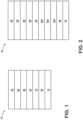
- the highly reflective mirror 10 includes a substrate 14, a first interface layer 18, a first reflective layer 22, a second interface layer 26, a plurality of tuning layers 30 including a low refractive index material (low index material) and a high refractive index material (high index material) wherein the high index material is HfO 2 , and a protective layer 42.
- the highly reflective mirror 10 has a reflectivity of at least 90 % over the wavelength range of 335 nm to 1000 nm at an AOI 45 °.
- the highly reflective mirror 10 includes a barrier layer 46.
- the highly reflective mirror 10 may include the substrate 14, the barrier layer 46, the first interface layer 18, the first reflective layer 22, the second interface layer 26, the plurality of tuning layers 30 including the low index material and the high index material wherein the high index material is HfO 2 , and the protective layer 42.
- the highly reflective mirror 10 has a reflectivity of at least 90 % over the wavelength range of 335 nm to 1000 nm at an AOI 45 °.
- the barrier layer 46 of the highly reflective mirror 10 may include a corrosion resistant layer, an abrasion resistant layer, a stress tuning layer, or a combination thereof.
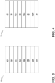
- the highly reflective mirror 10 consists of the substrate 14, the barrier layer 46, the first interface layer 18a, the first reflective layer 22a, the second interface layer 26a, a third interface layer 50, a second reflective layer 54, a fourth interface layer 58, the plurality of tuning layers 30, and the protective layer 42.
- the highly reflective mirror 10 has a reflectivity of at least 90 % over the wavelength range of 335 nm to 1000 nm at an AOI 45 °.
- the highly reflective mirror 10 includes the substrate 14, the first reflective layer 22a, the first interface layer 18b, the second interface layer 26b, the second reflective layer 54, the third interface layer 50a, the plurality of tuning layers 30, and the protective layer 42.
- the highly reflective mirror 10 has a reflectivity of at least 90 % over the wavelength range of 335 nm to 1000 nm at an AOI 45 °.
- the highly reflective mirror 10 may also include the barrier layer 46 which may include a corrosion resistant layer, an abrasion resistant layer, a stress tuning layer, or a combination thereof.
- the highly reflective mirror 10 consists of the substrate 14, the first reflective layer 22a, the barrier layer 46, the first interface layer 18c, the second reflective layer 54, the second interface layer 26c, the plurality of tuning layers 30, and the protective layer 42.
- the highly reflective mirror 10 has a reflectivity of at least 90 % over the wavelength range of 335 nm to 1000 nm at an AOI 45 °.
- the first interface layers 18, 18a, 18b, 18c, the second interface layers 26, 26a, 26b, 26c, the third interface layers 50, 50a, and the fourth interface layer 58 are used herein to specifically refer to the respective positioning of the stack embodiments provided for the highly reflective mirror 10 and are not meant to refer to a common set of materials used for the respective layer.
- the second interface layer 26 in FIG. 1 can be Al 2 O 3 and is coupled between the first reflective layer 22 and the plurality of tuning layers 30 while the second interface layer 26a in FIG. 2 is YbF 3 and is coupled between the first reflective layer 22a and the third interface layer 50.
- the materials than can be used for the second interface layer 26 and the second interface layer 26a are different in these two embodiments as determined by the adjacent layers the second interface layers 26, 26a are positioned, coupled, or layered in between.
- Table 1 below generally illustrates the five types of layers found in the stack embodiments provided for the highly reflective mirror 10 including the substrate 14, the barrier layer 46, at least one interface layer 18, 26, 50, 58, at least one reflective layer 22, 54, the plurality of tuning layers 30, and the protective layer 42.
- the layer possesses a high level of both chemical and mechanical durability YbF 3 , YF 3 , Si 3 N 4 , YbFO, Yb x F y O z , SiO 2 , AlON Tuning Layer(s)
- a low refractive index, high refractive index design is used for layer tuning.
- the materials must be low absorbing in the wavelength range of from .300 ⁇ m to 15.0 ⁇ m, and possess a medium to high level of chemical and mechanical durability HfO 2 , YbFO, YbF 3 , YF 3 , GdF 3 , Bi 2 O 3 Yb x F y O z Second Interface Layer (2 nd Layer)
- This layer is used to promote adhesion and galvanic compatibility of the tuning layers to the first and/or second reflective layer, the first and/or second reflective layers to the third interface layer, the first and/or second reflective layers to the first interface layer Bi 2 O 3 , ZnS, Nb 2 O 5 , TiO 2 , Ta 2 O 5 , Al 2 O 3 , InO 2 , InSnO Reflective Layer
- Silver (Ag) is used as the first and/or second reflective layer to provide high reflectance (high % R) in the wavelength range of .35 ⁇ m to >15 ⁇ m Ag, Au, Al, Rh, Cu, Pt
- This layer may also provide corrosion, abrasion (scratch), and stress resistance Si 3 N 4 , SiO 2 , TiAlN, TiAlSiN, TiO 2 , DLC, Al, CrN, Si x N y O z , NiCrN, Cr, NiCr, Ni, AlO x N y Substrate
- a light weight diamond turned optic/substrate for example 6061 aluminum (6061-Al) and other Al alloys, Mg alloys, Ti alloys, and ceramic alloys.
- a barrier layer is needed for metal alloys and its thickness is substrate dependent silica, fused silica and F-doped fused silica; and 6061-Al alloy, other light weight Al alloys Mg alloys, Ti alloys, silicon 1.
- the interface layers are also referred to as "adhesion" layers.
- Yb x F y O z is formed when oxygen is admitted during the depositions of YbF 3 .
- nYb +3 yF -1 + z O -2 so that the sum of the positive and the negative valances balance and there is no net charge to the coating layer. The same is true for Si x N y O z .
- One criterion for determining the thickness of the barrier layer 46 is the number of hours the article will have to withstand the salt fog test. The longer the duration of the salt fog test, the thicker the barrier layer 46 required. In some embodiments, for a salt fog test of 24 hours, a thickness of 10 ⁇ m may be sufficient for the barrier layer 46. In many applications, if the barrier layer 46 is too thick, it will cause distortion of the finished part with changes in temperature, but since the operational temperature is typically given in the specification, the thickness of the barrier layer 46 can be adjusted to prevent distortion. The differences in the thermal expansion coefficients of the barrier layer 46 and the substrate 14 will cause the optical figure, power, and irregularity, to change with changes in temperature ( ⁇ T).
- the barrier layer 46 is sufficiently thick so that it will cover or smooth out any high and irregular substrate peak-to-valley variations. Smoothing out such variations aids in polishing the surface to optimize surface quality.
- the surface quality is important in promoting adhesion on the entire surface and minimizing localized defect sites that may be caused by the peak-to-valley variations.
- the barrier layer 46 must be used between the silver layer and the substrate 14, or an Al layer deposited on any of the foregoing substrates, to create galvanic compatibility.
- the military standards for the use of dissimilar metals are defined in MIL-STD-889B and MIL-STD-1250. For systems that are expected to be exposed to harsh environments such as hot and humid and/or containing salts, these military documents suggest, that dissimilar metals should not be joined or interfaced if they exceed a galvanic potential difference of 0.25 V (in a high humid environment with no salts the potential difference can be >0.45V). In some of the engineering literature on corrosion, a potential difference of 0.15V is suggested for harsh salt environments.
- 6061-Al is considered an anodic material with a potential of 0.90 V while silver, a cathodic material, has a potential of 0.15 V, resulting in a potential difference of 0.75 V.
- the galvanic potential difference is >0.25 V for tin, 0.33 V for chromium, 0.33 V for zinc, 0.63 V for nickel, and 0.83 V for magnesium.
- TiAlN which is not covered by the claims, can also be effectively used as a barrier material (TiAlN can be made to behave like metal or like a dielectric depending on the Ti:Al ratio), in addition to (dielectric) coatings such as diamond like carbon (DLC), Al 2 O 3 , Si 3 N 4 , Si x N y O z , SiO 2 , and TiO 2 , which are not covered by the claims.
- DLC diamond like carbon
- Al 2 O 3 , Si 3 N 4 , Si x N y O z , SiO 2 , and TiO 2 which are not covered by the claims.
- CrN has been used with some success, care must be exercised in view of the intended application because its galvanic compatibility is border-line.
- the surface quality of the 6061-Al can play an important role in coupling the barrier layer 46 or first reflective layer 22.
- Large precipitate sites are formed by the "impurities" in the 6061-Al, some of which come from the controlled addition of materials required in order to meet material specifications for strength characteristics, and other impurities are simply contaminants.
- the large precipitates make it difficult to achieve a smooth surface, ⁇ 30 ⁇ rms, and some of the high peaks or nodules may result in poor adhesion (or cracking from stresses or voids) between the substrate 14 and the coating stack (silver layer, or silver layer covers differently), resulting in a defect site once the completed mirror is exposed to the environmental testing using both salt fog and long term humidity conditions.
- An approach to manage this condition is to deposit a very thick barrier layer 46 that results in an effective coating over these sites.
- the presence of large precipitates create a non-homogenous surface which makes it difficult to obtain a surface finish less than 60 ⁇ rms, the best results being about 30 ⁇ rms, which was obtained with difficulty.
- the presence of the nodules serves to illustrate why the presence of the barrier works to improve reflectivity. Without being held to any particular theory, the nodules can become defect sites where localized corrosion occurs when exposed to these harsh environments. They may result in poor adhesion, so coating cracks or falls off at sites exposing areas or creating pathways.
- a sufficiently thick barrier layer 46 can smooth out this surface and create a continuous film with good adhesion across the entire surface. If this barrier layer 46 surface is sufficiently thick, polishing the layer prior to the placement of additional coating layers would result in better surface finish in the approximate range of 5 ⁇ to 15 ⁇ .
- the barrier layer 46 is in the higher end of the range and must be sufficient to cover the nodules. If the substrate 14 is substantially free of the nodules then the barrier layer 46 can be at the lower end of the range. In addition, the use of ion assistance during the deposition of the barrier layer 46 will densify the barrier layer 46 and aid in providing a smooth surface.
- the barrier layer 46 would need to be relatively thin (e.g., 100 nm, 50 nm, or 80 nm) so as to not lose the reflectivity provided by the first reflective layer 22.
- the thickness must be sufficient to provide optimum reflection properties. If the first reflective metal layer 22 and/or second reflective metal layer 54 are too thin the film is not continuous and/or transmitting and if it is too thick durability can become a concern. Since both the first reflective layer 22 and the second reflective layer 54 are used together in stack configurations, the second reflective layer 54 has to be thick enough to provide some reflection but thin enough for light to access the reflective properties of the first reflective layer 22 positioned below (5 nm to 10 nm). In some embodiments, the second reflective layer 54 can have a thickness of 5 nm to 10 nm or 5 nm to 20 nm.
- the stack configuration can also be used with other reflective materials, for example Au, Al, Rh, Cu, Pt, Ni, to provide an enhanced durable, chemical, and mechanical performance, but with a change in spectral range and reflection intensity, but these configurations are not covered by the claims.
- other reflective materials for example Au, Al, Rh, Cu, Pt, Ni
- a thin film layer of silver is used for the second reflective layer.
- Silver is known to have the highest reflectivity, lowest polarization splitting, and lowest emissivity through this entire wavelength range.
- the thickness of the first interface layer 18, second interface layer 26, third interface layer 50, and fourth interface layer 58 are dependent on factors including what material is used for the respective interface layers. For example, whether the layer is the first interface layer 18, second interface layer 26, third interface layer 50, and fourth interface layer 58, and whether it is on the front surface (the surface of the reflective layer) or back surface (the layer on which the reflective layer is deposited) of the mirror.
- the interface layer used under the first reflective layer 22 or second reflective layer 54 may be present to promote adhesion so that optical considerations such as the absorption of reflection radiation are not a consideration. Consequently, the thickness of these interface layers is determined based on adhesion and not optical considerations. As a result, the interface layers positioned under the first reflective layer 22 and/or second reflective layer 54 can have a minimum thickness to provide the adhesion, but no maximum thickness because there is no absorption or optical concerns. However, the thickness of the interface layer used above the first and/or second reflective layers has to be carefully controlled so the reflection losses are minimized. In some embodiments not covered by the claims, for the interface layers used above the first and/or second reflective layers the thickness is in the range of 5 nm to 20 nm.
- the thickness of the interface layers used above the first and/or second reflective layers is in the range of 8 nm to 15 nm. In still other embodiments not covered by the claims, where the highly reflective mirror 10 is intended for use in the wavelength range of .300 ⁇ m to 15 ⁇ m, the thickness of the interface layers used above the first and/or second reflective layers is in the range of 1 nm to 100 nm to maximize the reflectance of the final highly reflective mirror 10.
- the first interface layer 18, second interface layer 26, third interface layer 50, and fourth interface layer 58 may have a thickness of 1 nm to 25 nm, 1 nm to 15 nm, 20 nm to 40 nm, or a combination thereof.
- Silver and gold have considerably lower oxide formation energies compared to other metals like titanium, aluminum, chromium, and nickel. Due to this lower oxide formation energy, silver and gold do not adhere well to many materials. It has been known for some time that ultra-thin films of Cr and Ni, or alloys of these metals, are excellent adhesion promoters for silver due to the metal-to-metal diffusion with Ag (or gold), along with metallic bonding strengths between Ag or Au and Cr or Ni. Because of the environments the mirrors disclosed herein will be exposed to, galvanic compatibility is critical and therefore must be considered when choosing the interface material. The galvanic potential difference at the interface of silver-Cr and silver-Ni are 0.45 V and 0.15 V respectively. Nickel or Al 2 O 3 may be used as the interface layers used under the first reflective layer 22 and/or second reflective layer 54 between the barrier layer 46 and the first and/or second reflective layers because the two materials are compatible.
- Al 2 O 3 has been discussed in the literature as an adhesion promoting material for certain metals; specifically the discussion involves Ag-Al 2 O 3 and Al-Al 2 O 3 nonstoichiometric interfaces, and how they influence adhesion ( W. Zhang and J. R. Smith, Nonstoichiometric interfaces and Al2O3 adhesion with Al and Ag, Physical Review Letters, Vol 85, No 15, Oct. 9, 2000, pages 3225-3228 ; Jiwei Feng, et al., Ab initio study of Ag/Al2O3 and Au/Al2O3 interfaces, Physical Review B, 72, 115423, Sep. 21, 2005 ).
- the interface layer due to the interface located on the backside of the first reflective layer 22 and/or second reflective layer 54, between the substrate 14 and the Ag layer, its upper limit of thickness is not limited by absorption, but should be monitored for stress considerations.
- the interface layer on the front side of the first reflective layer and/or second reflective layer 54, the interface layer, the layer deposited on top of the Ag layer, will have a thickness of interface that must be limited to minimize its absorption band in the LWIR band while obtaining optimum adhesion to Ag.
- ZnS is an additional non-conducting material that can be used as an adhesion layer in embodiments not covered by the claims, avoiding galvanic compatibility issues.
- ZnS has been found to be a successful interface material, for example, at the gold interface Au-ZnS-YbF 3 or the silver interface Ag-ZnS-YbF 3 .
- the first reflective layer 22 is aluminum
- using an oxide can promote oxidation of some of the aluminum surface and reduce reflectivity in the UV and low end of the visible wavelengths; in these embodiments, a fluoride compound can be used as an alternative to prevent this oxidation.
- fluoride compounds such as MgF 2 or AlF 3 can work best for an aluminum first reflective layer 22 so the aluminum surface is not oxidized and the metals or metal compounds can absorb well.
- the first interface layer 18 can be ZnS when applied to a gold and/or platinum first and or second reflective layer 22, 54.
- the thicknesses of the plurality of tuning layers 30 depend on the optimization necessary to achieve the required spectral performance while simultaneously optimizing the protection necessary to pass the required tests, for example, the salt fog and humidity tests.
- the thickness of these layers can vary significantly depending on application and materials used.
- the highly reflective mirror 10 can have a reflectivity of at least 90 % over the wavelength range of 300 nm to 15 ⁇ m at an AOI 45 °; the highly reflective mirror 10 can have a reflectivity of at least 90 % over the wavelength range of 300 nm to 1000 nm at an AOI 45 °; the highly reflective mirror 10 has a reflectivity of at least 90 % over the wavelength range of 335 nm to 1000 nm at an AOI 45 °; the highly reflective mirror 10 can have a reflectivity of at least 90 % over the wavelength range of 300 nm to 400 nm at an AOI 45 °; the highly reflective mirror 10 has a reflectivity of at least 90 % over the wavelength range of 335 nm to 400 nm at an AOI 45 °.
- the thickness of the plurality of tuning layers 30 will have to be varied and a combination of low, medium and/or high index materials are used. In some embodiments not covered by the claims, the thickness of the plurality of tuning layers 30 is in the range of 75 nm to 300 nm. In some embodiments not covered by the claims, the protective layer 42 applied on top of the plurality of tuning layers 30 has a thickness in the range of 60 nm to 200 nm.
- Corning has developed thin film deposition processes, for example the process described in U.S. Pat. No. 7,242,843 , which can be used for ytterbium fluoride (YbF 3 ) and yttrium fluoride (YF 3 ), both of which are low refractive index materials.
- YbF 3 ytterbium fluoride
- YF 3 yttrium fluoride
- the low refractive index materials were used in combination with high refractive index materials, for example, niobium pentoxide (Nb 2 O 5 ) and zinc sulfide (ZnS).
- HfO 2 as the high refractive index material and the use of YbFO as an exemplary low refractive index fluoride material can be used to provide a coating combination of YbFO-HfO 2 -YbFO that can be tuned for improved reflectivity in the NUV and LWIR ranges, such as in the 330 nm to 400 nm band.
- oxygen is used during the deposition of the YbF 3 material the deposited layer becomes a ytterbium oxyfluoride material that is designated herein as Yb x F y O z , and the thickness of this layer is the in the same range as that for YbF 3 .
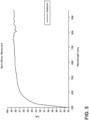
- FIG. 5 demonstrates the drop in silver's reflectivity for wavelengths below 450 nm. This drop in reflectivity below 450 nm has been found herein to be adjusted and tuned using HfO 2 as the high refractive index material in the plurality of tuning layers 30 combined with low refractive index materials such as YbFO.
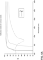
- Another technique that can be used herein is to add a very thin gold (Ag) or aluminum (Al) layer on top of a thick metal layer or highly polished metal substrate 14. These materials, in particular aluminum, have improved reflection properties in the NUV as shown in FIGS. 6A and 6B .
- the ability to add a layer of aluminum or other metal to a thick substrate 14 such as 6160-A1 has been described in U.S. Patent Application No. 14/865,380 and U.S. Patent Application No. 14/679,339 .
- FIG. 6B in particular shows the improved reflectance in the 330 nm to 400 nm wavelength range for aluminum over both silver and gold.
- FIG. 7 demonstrates the improved reflectivity of HfO 2 as one of the plurality of tuning layers 30 used in the highly reflective mirror 10.
- the use of HfO 2 as one of the tuning layers can replace other high index materials such as Al 2 O 3 , SiO 2 , Nb 2 O 5 , TiO 2 , and various fluorides since it has a low absorption in the NUV and extends the silver stack reflectivity compared to the other high index materials mentioned above.
- FIG. 8 shows how the HfO 2 can extend the band by greater than 15 nm compared to the Nb 2 O 5 material.
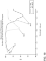
- FIG. 10 demonstrates IR reflectance for a thin film layer of HfO 2 on silver and the IR reflectance for a thin film layer of Nb 2 O 5 on silver, respectively.
- the plot points out the respective O-H stretch, Nb-O stretch, and the Hf-O stretch for the HfO 2 and Nb 2 O 5 films respectively measured at an angle of 45 °.
- the thickness of the layer is in the range of 150 nm to 350 nm.
- YbF 3 , YF 3 , and Si 3 N 4 Materials that found to be useful as protective layers 42 in embodiments not covered by the claims are YbF 3 , YF 3 , and Si 3 N 4 .
- YbF 3 and YF 3 low refractive index
- GdF 3 medium refractive index in VIS range
- ZnS and Bi 2 O 3 both high refractive index
- the protective layer 42 comprises at least one material selected from the group consisting of YbF 3 , YF 3 , Si 3 N 4 , and combinations thereof.
- the protective layer 42 consists essentially of at least one material selected from the group consisting of YbF 3 , YF 3 , Si 3 N 4 , and combinations thereof.
- the protective layer 42 consists of at least one material selected from the group consisting of YbF 3 , YF 3 , Si 3 N 4 , and combinations thereof.
- Silver can react with various substances that may be present in the atmosphere, for example salts, acids, and sulfur compounds.
- Well known examples include silver tarnishing, which is the formation of black silver sulfide (Ag 2 S) by the reaction of Ag 0 with sulfur containing compounds, and silver corrosion, which results from the reaction of Ag 0 with halogen-containing substances in the atmosphere, the most common of which is probably NaCl and HCl ( T. E. Graedel, Corrosion Mechanisms for Silver Exposed to the Atmosphere, J. Electrochemical Society Vol. 139, No. 7, pages 1963-1969 (1992 ), and D.
- the Vickers hardness (HV) of silver is 100 HV (electro-deposited), which is low compared to the other end of the HV spectrum where diamond has a value of 10,000 HV.
- HV Vickers hardness
- the protective layer 42 is needed to minimize damaging the silver surface in embodiments not covered by the claims.
- the protective layer 42 In order to be effective, the protective layer 42 must be (1) sufficiently dense such that no pathways are provided from the optic's surface to silver and interface layers, (2) insoluble in alkali and acidic environments, (3) mechanically hard to provide scratch resistance, and (4) have either (a) only minimal absorption throughout the entire wavelength range of interest, .300 ⁇ m to 15 ⁇ m in the present case, or (b) no absorption over the .300 ⁇ m to 15 ⁇ m wavelength range. Silicon nitride, Si 3 N 4 , was tested for its alkali diffusion properties, solubility in alkali solution and for its mechanical hardness properties, and was found to provide a very durable and chemically resistant coating.
- this material was unfortunately found to have an absorption band at approximately 9.1 ⁇ m, this disclosure shown that if the Si 3 N 4 is sufficiently thin it can be used.
- the exact thickness depends on the throughput of the system for the band range. For some applications this band is of no interest so the thickness is of limited consequence.
- the barrier layer 46, the first interface layer 18, the second interface layer 26, the third interface layer 50, the fourth interface layer 58, the first reflective layer 22, the second reflective layer 54, and the plurality of tuning layers 30 can each, independently, be deposited using ion assistance.
- ion assistance is not used or is used for only part of the deposition process.
- the protective layer 42 is deposited using ion assistance.
- these materials can also be deposited using other processes and will perform well over the .300 ⁇ m to 15 ⁇ m wavelength range, with the provision that the process can be optimized for the desired characteristics.
- Ion assist deposition techniques under the correct conditions, can optimize stoichiometry, density, and possibly structure.
- different techniques can be used to prepare a mirror having the .300 ⁇ m to 15 ⁇ m wavelength range characteristics as described herein. The techniques selected were dependent on the materials being used and the desired properties to be achieved.
- Process considerations for depositing the stack must be taken into consideration and these considerations are material and interface dependent. Because film density and stoichiometry are critical, ion beam bombardment is used during the deposition. Ion energies and densities must be adjusted appropriately so as to densify, but not damage the film.
- Gas ratios of Ar, N 2 , O 2 can be adjusted to control the desired stoichiometry, with the warning that O 2 should either: (a) not be used during deposition of the Ag layer or the interface layer positioned above the first and/or second reflective layers afterwards, or (b) not be used at the beginning of the deposition of the interface layer positioned above the first and/or second reflective layers, but added into the deposition process after a very thin, 3-5 nm interface layer has been applied to the top of the Ag layer.
- the objective is to have the interface layer used above the first and/or second reflective layers, for example an oxide such as Al 2 O 3 , adhere to the second reflective layer while not exposing the second reflective layer surface to excessive O 2 before the Al 2 O 3 deposition, while maintaining substantially all of the Al 2 O 3 at a stoichiometric or near stoichiometric Al:O ratio.
- the following process criteria may be used for the stack.
- Al 2 O 3 is used as the barrier layer 46 in embodiments not covered by the claims, then its initial partial pressures of Ar--O 2 gases must be adjusted to create the desired Al x O y stoichiometry needed to optimize adhesion at the Al-Al x O y interface.
- the Al x O y --Ag interface partial pressures are different than the Al--Al x O y interface to achieve optimum adhesion so the process must be adjusted towards the end of this barrier layer 46.
- the Al x O y stoichiometry needed for optimum adhesion at either the Al or Ag interfaces are discussed in the references 4 above. Their partial pressures or gas flow ratios will be dependent on deposition rates, pumping speeds and deposition volumes.
- stoichiometry is also critical at the oxide-fluoride interfaces to obtaining optimum adhesion.
- terminating the layer so that it is a stoichiometric oxide is important; while the fluoride at the interface should be an oxyfluoride.
- bombardment energies and gas ratios should be adjusted to obtain optimum film density.
- densifying fluoride materials one has to consider ion energies that will not dissociate the fluorine atoms of the growing film. If this occurs, the film will become very unstable and spectral shifting will be observed.
- the process is directed to the highly reflective mirror 10 for use in the wavelength range of .300 ⁇ m to 15 ⁇ m.
- the substrate 14 that can be used in making the highly reflective mirror 10 can be selected from the group consisting of diamond turned aluminum alloys.
- the substrate 14 is 6061-Al alloy.
- the substrate 14 is fused silica.
- the present disclosure is also directed to a method 100, which is not covered by the claims, for making the highly reflective mirror 10 for use in the wavelength range of .300 ⁇ m to 15 ⁇ m.
- the following method 100 which is not covered by the scope of the claims, comprises the steps of:
- the barrier layer 46 material is selected from the group consisting of Si 3 N 4 , SiO 2 , TiAlN, TiAlSiN, TiO 2 , DLC, Al, and CrN;
- the first interface layer 18 material is selected from the group consisting of Al 2 O 3 , TiO 2 , Bi 2 O 3 , ZnS, Ni, Monel (Ni--Cu), Ti, and Pt;
- the first reflective layer 22 and/or second reflective layer 54 is at least one material selected from the group consisting of Ag, Au, Al, Rh, Cu, Pt, and Ni;
- the second interface layer 26 is at least one material selected from the group consisting of SiO 2 , Si 3 N 4 , NbzOs, TiO 2 , Ta 2 O 5 , and Al 2 O 3 ;
- the plurality of tuning layers 30 includes the high index material of HfO 2 and one or more additional materials selected from the group consisting of YbF 3 , YF 3 , GdF 3 , and Bi
- the descriptions outlining and teaching the barrier layer 46, the first interface layer 18, the second interface layer 26, the third interface layer 50, the fourth interface layer 58, the first reflective layer 22, the second reflective layer 54, the plurality of tuning layers 30, and the protective layer 42 previously discussed, which can be used in any combination, can be applied to the method 100 for making the highly reflective mirror 10 for use in the wavelength range of .300 ⁇ m to 15 ⁇ m.
- the substrate 14 may be coupled on its top side to the first reflective layer 22a, the first reflective layer 22a may be coupled on its top side to the first interface layer 18b, the first interface layer 18b may be coupled on its top side to the second interface layer 26b, the second interface layer 26b may be coupled on its top side to the second reflective layer 54, the second reflective layer 54 may be coupled on its top side to the third interface layer 50a, the third interface layer 50a may be coupled on its top side to the plurality of tuning layers 30, and the plurality of tuning layers 30 may be coupled on the top side of its top layer to the protective layer 42.
- 9A-9B are graphs showing the wavelength versus percent reflectance for a Al-Ag stack with a HfO 2 -YbF 3 tuning layer having an average reflectivity of greater than 92 % from 300 nm to 1000 nm, and the wavelength versus percent reflectance for a Al-Ag stack with a HfO 2 -YbF 3 tuning layer having an average reflectivity of greater than 92 % from 300 nm to 8000 nm, respectively.
- Table 2 An example stack used as the highly reflective mirror according to FIG. 3 Protective Layer YbFO 83.76 nm Plurality of Tuning Layers HfO 2 43.31 nm YbFO 24.36 nm HfO 2 34.74 nm YbFO 53.47 nm Al 2 O 3 45.45 nm YbFO 51.72 nm HfO 2 36.24 nm YbFO 32.68 nm HfO 2 38.82 nm Third Interface Layer Al 2 O 3 30 nm Second Reflective Layer Ag 10 nm Second Interface Layer Al 2 O 3 10 nm First Interface Layer YbF 3 5 nm First Reflective Layer Al 200 nm Substrate Fused Silica 619 nm
- the substrate 14 may be coupled on its top side to the barrier layer 46, the barrier layer 46 may be coupled on its top side to the first interface layer 18, the first interface layer 18 may be coupled on its top side to the first reflective layer 22, the first reflective layer 22 may be coupled on its top side to the second interface layer 26, the second interface layer 26 may be coupled on its top side to the plurality of tuning layers 30, and the plurality of tuning layers 30 may be coupled on the top side of its top layer to the protective layer 42.
- Table 3 An example stack used as the highly reflective mirror according to FIG. 1
- Second Interface Layer Al 2 O 3 20 - 40 nm
- This embodiment is according to claim 1.
- Table 4 An example stack used as the highly reflective mirror according to FIG. 2 Protective Layer YbFO 50 - 100 nm Plurality of Tuning Layers HfO 2 20 - 60 nm YbFO 20 - 60 nm HfO 2 20 - 60 nm Fourth Interface Layer Al 2 O 3 20 - 40 nm Second Reflective Layer Ag 1 - 30 nm Third Interface Layer Al 2 O 3 1 - 15 nm Second Interface Layer YbF 3 1 - 15 nm First Reflective Layer Al 1 - 250 nm First Interface Layer YbF 3 1 - 15 nm Barrier Layer Nb 2 O 5 10 - 100 nm YbF x O y 10 - 100 nm Nb 2 O 5 10 - 100 nm YbF x O y 10 - 100 nm Nb 2 O 5 10 - 100 nm YbF x O y 10 - 100 nm Nb 2 O 5 10 - 100 nm Yb
- This embodiment is according to claim 2.
- Table 5 An example stack used as the highly reflective mirror according to FIG. 4 Protective Layer YbFO 50 - 100 nm Tuning Layers HfO 2 20 - 60 nm YbFO 20 - 60 nm HfO 2 20 - 60 nm Second Interface Layer Al 2 O 3 20 - 40 nm Second Reflective Layer Ag 1 - 30 nm First Interface Layer Al 2 O 3 1 - 15 nm Barrier Layer Nb 2 O 5 10 - 100 nm YbF x O y 10 - 100 nm Nb 2 O 5 10 - 100 nm YbF x O y 10 - 100 nm Nb 2 O 5 10 - 100 nm Nb 2 O 5 10 - 100 nm First Reflective Layer Al 50 - 400 nm Substrate 6061-Al 500 - 750 nm
Landscapes
- Physics & Mathematics (AREA)
- Chemical & Material Sciences (AREA)
- General Physics & Mathematics (AREA)
- Optics & Photonics (AREA)
- Chemical Kinetics & Catalysis (AREA)
- Engineering & Computer Science (AREA)
- Materials Engineering (AREA)
- Mechanical Engineering (AREA)
- Metallurgy (AREA)
- Organic Chemistry (AREA)
- Optical Elements Other Than Lenses (AREA)
- Laminated Bodies (AREA)
Applications Claiming Priority (2)
| Application Number | Priority Date | Filing Date | Title |
|---|---|---|---|
| US201762520833P | 2017-06-16 | 2017-06-16 | |
| PCT/US2018/037609 WO2018232162A1 (en) | 2017-06-16 | 2018-06-14 | Extending the reflection bandwidth of silver coating stacks for highly reflective mirrors |
Publications (2)
| Publication Number | Publication Date |
|---|---|
| EP3639069A1 EP3639069A1 (en) | 2020-04-22 |
| EP3639069B1 true EP3639069B1 (en) | 2024-10-23 |
Family
ID=62817099
Family Applications (1)
| Application Number | Title | Priority Date | Filing Date |
|---|---|---|---|
| EP18737483.0A Active EP3639069B1 (en) | 2017-06-16 | 2018-06-14 | Extending the reflection bandwidth of silver coating stacks for highly reflective mirrors |
Country Status (4)
| Country | Link |
|---|---|
| US (1) | US11143800B2 (enExample) |
| EP (1) | EP3639069B1 (enExample) |
| JP (1) | JP7280198B2 (enExample) |
| WO (1) | WO2018232162A1 (enExample) |
Families Citing this family (12)
| Publication number | Priority date | Publication date | Assignee | Title |
|---|---|---|---|---|
| WO2018075881A1 (en) * | 2016-10-21 | 2018-04-26 | Gentex Corporation | Antireflection coatings |
| CN110221368B (zh) * | 2019-05-31 | 2020-11-17 | 西安工业大学 | 单元素多层红外高反膜及其制备方法 |
| EP3771930A1 (en) * | 2019-07-31 | 2021-02-03 | Ningbo Radi-Cool Advanced Energy Technologies Co., Ltd. | Solar reflecting film and preparation method thereof |
| AU2020210219B2 (en) * | 2019-07-31 | 2022-04-07 | Ningbo Radi-Cool Advanced Energy Technologies Co., Ltd. | Solar reflecting film and preparation method thereof |
| JP7567797B2 (ja) * | 2019-09-13 | 2024-10-16 | 株式会社レゾナック | 積層体およびその製造方法 |
| CN111733390A (zh) * | 2019-12-30 | 2020-10-02 | 宁波瑞凌新能源科技有限公司 | 一种用于双反射层膜中的复合阻隔材料及其应用 |
| CN111312069A (zh) * | 2020-04-03 | 2020-06-19 | 武汉华星光电技术有限公司 | 一种背光板、其制备方法以及背光模组 |
| EP4166998A4 (en) * | 2020-06-12 | 2024-09-04 | Nitto Denko Corporation | MIRROR EFFECT FILM LAMINATE, AND MIRROR ELEMENT |
| CN113151783B (zh) * | 2021-03-02 | 2022-04-19 | 中国电器科学研究院股份有限公司 | 一种组合型反射膜及其制备方法 |
| JP7703214B2 (ja) * | 2021-08-23 | 2025-07-07 | 東海光学株式会社 | 青色レーザー光用ミラーの製造方法 |
| CN117991427B (zh) * | 2024-03-13 | 2024-08-09 | 同济大学 | 一种低损耗、高反射率的193nm薄膜及其制备方法 |
| CN119101885A (zh) * | 2024-08-01 | 2024-12-10 | 深圳市原速光电科技有限公司 | 镀膜件及其制备方法 |
Family Cites Families (25)
| Publication number | Priority date | Publication date | Assignee | Title |
|---|---|---|---|---|
| US5525199A (en) | 1991-11-13 | 1996-06-11 | Optical Corporation Of America | Low pressure reactive magnetron sputtering apparatus and method |
| CH685138A5 (de) | 1993-04-15 | 1995-03-31 | Balzers Hochvakuum | Hochreflektierender Silberspiegel. |
| US6128126A (en) | 1993-04-15 | 2000-10-03 | Balzers Aktiengesellschaft | High-reflection silver mirror |
| JPH11311704A (ja) * | 1998-02-26 | 1999-11-09 | Nikon Corp | 紫外光用ミラー |
| US6695458B2 (en) | 2000-09-12 | 2004-02-24 | Canon Kabushiki Kaisha | High-reflectance silver mirror and reflecting optical element |
| JP2003270725A (ja) * | 2002-03-14 | 2003-09-25 | Sony Corp | 投影用スクリーン及びその製造方法 |
| JP2006010930A (ja) | 2003-06-27 | 2006-01-12 | Asahi Glass Co Ltd | 高反射鏡 |
| US7678459B2 (en) * | 2004-09-21 | 2010-03-16 | Guardian Industries Corp. | First surface mirror with silicon-metal oxide nucleation layer |
| US7838134B2 (en) * | 2004-11-23 | 2010-11-23 | Lawrence Livermore National Security, Llc | Durable silver mirror with ultra-violet thru far infra-red reflection |
| TWI282434B (en) * | 2005-06-15 | 2007-06-11 | Asia Optical Co Inc | Film layer structure of optical lens |
| US7242843B2 (en) | 2005-06-30 | 2007-07-10 | Corning Incorporated | Extended lifetime excimer laser optics |
| US7342716B2 (en) * | 2005-10-11 | 2008-03-11 | Cardinal Cg Company | Multiple cavity low-emissivity coatings |
| JP5229075B2 (ja) * | 2008-07-28 | 2013-07-03 | 日本電気硝子株式会社 | 広帯域反射鏡 |
| CN101806927B (zh) | 2010-02-25 | 2013-09-11 | 海洋王照明科技股份有限公司 | 一种高反膜及其制备方法 |
| JPWO2012008587A1 (ja) * | 2010-07-16 | 2013-09-09 | 旭硝子株式会社 | 赤外線反射基板および合わせガラス |
| WO2012067924A1 (en) * | 2010-11-18 | 2012-05-24 | Corning Incorporated | Enhanced, protected silver coatings on aluminum for optical mirror and method of making same |
| JP5647924B2 (ja) | 2011-03-18 | 2015-01-07 | 富士フイルム株式会社 | 光学部材の製造方法 |
| CA2901782C (en) * | 2013-02-20 | 2018-07-17 | Saint-Gobain Glass France | Pane with thermal radiation reflecting coating |
| US9488760B2 (en) * | 2013-02-28 | 2016-11-08 | Corning Incorporated | Enhanced, durable silver coating stacks for highly reflective mirrors |
| US20150285958A1 (en) * | 2014-04-02 | 2015-10-08 | Corning Incorporated | Lightweight reflecting optics |
| US9971073B2 (en) | 2014-04-14 | 2018-05-15 | Corning Incorporated | Enhanced performance metallic based optical mirror substrates |
| DE102014108679A1 (de) * | 2014-06-20 | 2015-12-24 | Fraunhofer-Gesellschaft zur Förderung der angewandten Forschung e.V. | Optisches Element mit einer reflektierenden Beschichtung |
| US20160097885A1 (en) | 2014-10-03 | 2016-04-07 | Corning Incorporated | Mirror substrates with highly finishable corrosion-resistant coating |
| DE102015102496B4 (de) | 2014-10-27 | 2024-06-20 | Almeco Gmbh | Temperatur- und korrosionsstabiler Oberflächenreflektor |
| DE102015103494B4 (de) | 2015-03-10 | 2020-07-16 | Friedrich-Schiller-Universität Jena | Verfahren zur Herstellung eines Reflektorelements und Reflektorelement |
-
2018
- 2018-06-06 US US16/001,280 patent/US11143800B2/en active Active
- 2018-06-14 JP JP2019569377A patent/JP7280198B2/ja active Active
- 2018-06-14 WO PCT/US2018/037609 patent/WO2018232162A1/en not_active Ceased
- 2018-06-14 EP EP18737483.0A patent/EP3639069B1/en active Active
Also Published As
| Publication number | Publication date |
|---|---|
| JP7280198B2 (ja) | 2023-05-23 |
| US20180364402A1 (en) | 2018-12-20 |
| US11143800B2 (en) | 2021-10-12 |
| WO2018232162A1 (en) | 2018-12-20 |
| EP3639069A1 (en) | 2020-04-22 |
| WO2018232162A8 (en) | 2019-06-27 |
| JP2020523642A (ja) | 2020-08-06 |
Similar Documents
| Publication | Publication Date | Title |
|---|---|---|
| EP3639069B1 (en) | Extending the reflection bandwidth of silver coating stacks for highly reflective mirrors | |
| US10955594B2 (en) | Enhanced, durable silver coating stacks for highly reflective mirrors | |
| TWI589448B (zh) | 溫度及腐蝕穩定的表面反射器 | |
| US10605966B2 (en) | Enhanced performance metallic based optical mirror substrates | |
| US10429549B2 (en) | Optical element comprising a reflective coating | |
| US7838134B2 (en) | Durable silver mirror with ultra-violet thru far infra-red reflection | |
| US20110003125A1 (en) | Glass product and a method for manufacturing a glass product | |
| US20100035036A1 (en) | Durable antireflective multispectral infrared coatings | |
| US20180029931A1 (en) | Method for Producing a Reflector Element and Reflector Element | |
| Phillips et al. | Progress toward high-performance reflective and anti-reflection coatings for astronomical optics | |
| JP2019502158A (ja) | 応力補償型反射性コーティングを備える鏡 | |
| US5770270A (en) | Protective and/or reflectivity enhancement of noble metal | |
| US20190064398A1 (en) | Durable silver-based mirror coating employing nickel oxide | |
| Laux et al. | Thorium-free interference coatings for infrared applications | |
| CN114196924A (zh) | 一种铜基板表面真空紫外铝反射镜的镀膜方法 | |
| JP2005345509A (ja) | 表面鏡およびその製造方法 |
Legal Events
| Date | Code | Title | Description |
|---|---|---|---|
| STAA | Information on the status of an ep patent application or granted ep patent |
Free format text: STATUS: UNKNOWN |
|
| STAA | Information on the status of an ep patent application or granted ep patent |
Free format text: STATUS: THE INTERNATIONAL PUBLICATION HAS BEEN MADE |
|
| PUAI | Public reference made under article 153(3) epc to a published international application that has entered the european phase |
Free format text: ORIGINAL CODE: 0009012 |
|
| STAA | Information on the status of an ep patent application or granted ep patent |
Free format text: STATUS: REQUEST FOR EXAMINATION WAS MADE |
|
| 17P | Request for examination filed |
Effective date: 20200108 |
|
| AK | Designated contracting states |
Kind code of ref document: A1 Designated state(s): AL AT BE BG CH CY CZ DE DK EE ES FI FR GB GR HR HU IE IS IT LI LT LU LV MC MK MT NL NO PL PT RO RS SE SI SK SM TR |
|
| AX | Request for extension of the european patent |
Extension state: BA ME |
|
| DAV | Request for validation of the european patent (deleted) | ||
| DAX | Request for extension of the european patent (deleted) | ||
| STAA | Information on the status of an ep patent application or granted ep patent |
Free format text: STATUS: EXAMINATION IS IN PROGRESS |
|
| 17Q | First examination report despatched |
Effective date: 20220324 |
|
| GRAP | Despatch of communication of intention to grant a patent |
Free format text: ORIGINAL CODE: EPIDOSNIGR1 |
|
| STAA | Information on the status of an ep patent application or granted ep patent |
Free format text: STATUS: GRANT OF PATENT IS INTENDED |
|
| INTG | Intention to grant announced |
Effective date: 20240529 |
|
| GRAS | Grant fee paid |
Free format text: ORIGINAL CODE: EPIDOSNIGR3 |
|
| GRAA | (expected) grant |
Free format text: ORIGINAL CODE: 0009210 |
|
| STAA | Information on the status of an ep patent application or granted ep patent |
Free format text: STATUS: THE PATENT HAS BEEN GRANTED |
|
| AK | Designated contracting states |
Kind code of ref document: B1 Designated state(s): AL AT BE BG CH CY CZ DE DK EE ES FI FR GB GR HR HU IE IS IT LI LT LU LV MC MK MT NL NO PL PT RO RS SE SI SK SM TR |
|
| P01 | Opt-out of the competence of the unified patent court (upc) registered |
Free format text: CASE NUMBER: APP_52377/2024 Effective date: 20240918 |
|
| REG | Reference to a national code |
Ref country code: GB Ref legal event code: FG4D |
|
| REG | Reference to a national code |
Ref country code: CH Ref legal event code: EP |
|
| REG | Reference to a national code |
Ref country code: DE Ref legal event code: R096 Ref document number: 602018075713 Country of ref document: DE |
|
| REG | Reference to a national code |
Ref country code: IE Ref legal event code: FG4D |
|
| REG | Reference to a national code |
Ref country code: LT Ref legal event code: MG9D |
|
| REG | Reference to a national code |
Ref country code: NL Ref legal event code: MP Effective date: 20241023 |
|
| REG | Reference to a national code |
Ref country code: AT Ref legal event code: MK05 Ref document number: 1735283 Country of ref document: AT Kind code of ref document: T Effective date: 20241023 |
|
| PG25 | Lapsed in a contracting state [announced via postgrant information from national office to epo] |
Ref country code: NL Free format text: LAPSE BECAUSE OF FAILURE TO SUBMIT A TRANSLATION OF THE DESCRIPTION OR TO PAY THE FEE WITHIN THE PRESCRIBED TIME-LIMIT Effective date: 20241023 |
|
| PG25 | Lapsed in a contracting state [announced via postgrant information from national office to epo] |
Ref country code: NL Free format text: LAPSE BECAUSE OF FAILURE TO SUBMIT A TRANSLATION OF THE DESCRIPTION OR TO PAY THE FEE WITHIN THE PRESCRIBED TIME-LIMIT Effective date: 20241023 |
|
| PG25 | Lapsed in a contracting state [announced via postgrant information from national office to epo] |
Ref country code: HR Free format text: LAPSE BECAUSE OF FAILURE TO SUBMIT A TRANSLATION OF THE DESCRIPTION OR TO PAY THE FEE WITHIN THE PRESCRIBED TIME-LIMIT Effective date: 20241023 Ref country code: PT Free format text: LAPSE BECAUSE OF FAILURE TO SUBMIT A TRANSLATION OF THE DESCRIPTION OR TO PAY THE FEE WITHIN THE PRESCRIBED TIME-LIMIT Effective date: 20250224 Ref country code: IS Free format text: LAPSE BECAUSE OF FAILURE TO SUBMIT A TRANSLATION OF THE DESCRIPTION OR TO PAY THE FEE WITHIN THE PRESCRIBED TIME-LIMIT Effective date: 20250223 |
|
| PG25 | Lapsed in a contracting state [announced via postgrant information from national office to epo] |
Ref country code: FI Free format text: LAPSE BECAUSE OF FAILURE TO SUBMIT A TRANSLATION OF THE DESCRIPTION OR TO PAY THE FEE WITHIN THE PRESCRIBED TIME-LIMIT Effective date: 20241023 |
|
| PG25 | Lapsed in a contracting state [announced via postgrant information from national office to epo] |
Ref country code: BG Free format text: LAPSE BECAUSE OF FAILURE TO SUBMIT A TRANSLATION OF THE DESCRIPTION OR TO PAY THE FEE WITHIN THE PRESCRIBED TIME-LIMIT Effective date: 20241023 |
|
| PG25 | Lapsed in a contracting state [announced via postgrant information from national office to epo] |
Ref country code: ES Free format text: LAPSE BECAUSE OF FAILURE TO SUBMIT A TRANSLATION OF THE DESCRIPTION OR TO PAY THE FEE WITHIN THE PRESCRIBED TIME-LIMIT Effective date: 20241023 |
|
| PG25 | Lapsed in a contracting state [announced via postgrant information from national office to epo] |
Ref country code: NO Free format text: LAPSE BECAUSE OF FAILURE TO SUBMIT A TRANSLATION OF THE DESCRIPTION OR TO PAY THE FEE WITHIN THE PRESCRIBED TIME-LIMIT Effective date: 20250123 |
|
| PG25 | Lapsed in a contracting state [announced via postgrant information from national office to epo] |
Ref country code: AT Free format text: LAPSE BECAUSE OF FAILURE TO SUBMIT A TRANSLATION OF THE DESCRIPTION OR TO PAY THE FEE WITHIN THE PRESCRIBED TIME-LIMIT Effective date: 20241023 Ref country code: LV Free format text: LAPSE BECAUSE OF FAILURE TO SUBMIT A TRANSLATION OF THE DESCRIPTION OR TO PAY THE FEE WITHIN THE PRESCRIBED TIME-LIMIT Effective date: 20241023 Ref country code: GR Free format text: LAPSE BECAUSE OF FAILURE TO SUBMIT A TRANSLATION OF THE DESCRIPTION OR TO PAY THE FEE WITHIN THE PRESCRIBED TIME-LIMIT Effective date: 20250124 |
|
| PG25 | Lapsed in a contracting state [announced via postgrant information from national office to epo] |
Ref country code: PL Free format text: LAPSE BECAUSE OF FAILURE TO SUBMIT A TRANSLATION OF THE DESCRIPTION OR TO PAY THE FEE WITHIN THE PRESCRIBED TIME-LIMIT Effective date: 20241023 |
|
| PG25 | Lapsed in a contracting state [announced via postgrant information from national office to epo] |
Ref country code: RS Free format text: LAPSE BECAUSE OF FAILURE TO SUBMIT A TRANSLATION OF THE DESCRIPTION OR TO PAY THE FEE WITHIN THE PRESCRIBED TIME-LIMIT Effective date: 20250123 |
|
| PG25 | Lapsed in a contracting state [announced via postgrant information from national office to epo] |
Ref country code: SM Free format text: LAPSE BECAUSE OF FAILURE TO SUBMIT A TRANSLATION OF THE DESCRIPTION OR TO PAY THE FEE WITHIN THE PRESCRIBED TIME-LIMIT Effective date: 20241023 |
|
| PGFP | Annual fee paid to national office [announced via postgrant information from national office to epo] |
Ref country code: DE Payment date: 20250509 Year of fee payment: 8 |
|
| PG25 | Lapsed in a contracting state [announced via postgrant information from national office to epo] |
Ref country code: DK Free format text: LAPSE BECAUSE OF FAILURE TO SUBMIT A TRANSLATION OF THE DESCRIPTION OR TO PAY THE FEE WITHIN THE PRESCRIBED TIME-LIMIT Effective date: 20241023 |
|
| PG25 | Lapsed in a contracting state [announced via postgrant information from national office to epo] |
Ref country code: EE Free format text: LAPSE BECAUSE OF FAILURE TO SUBMIT A TRANSLATION OF THE DESCRIPTION OR TO PAY THE FEE WITHIN THE PRESCRIBED TIME-LIMIT Effective date: 20241023 |
|
| PG25 | Lapsed in a contracting state [announced via postgrant information from national office to epo] |
Ref country code: RO Free format text: LAPSE BECAUSE OF FAILURE TO SUBMIT A TRANSLATION OF THE DESCRIPTION OR TO PAY THE FEE WITHIN THE PRESCRIBED TIME-LIMIT Effective date: 20241023 |
|
| REG | Reference to a national code |
Ref country code: DE Ref legal event code: R097 Ref document number: 602018075713 Country of ref document: DE |
|
| PG25 | Lapsed in a contracting state [announced via postgrant information from national office to epo] |
Ref country code: SK Free format text: LAPSE BECAUSE OF FAILURE TO SUBMIT A TRANSLATION OF THE DESCRIPTION OR TO PAY THE FEE WITHIN THE PRESCRIBED TIME-LIMIT Effective date: 20241023 |
|
| PG25 | Lapsed in a contracting state [announced via postgrant information from national office to epo] |
Ref country code: CZ Free format text: LAPSE BECAUSE OF FAILURE TO SUBMIT A TRANSLATION OF THE DESCRIPTION OR TO PAY THE FEE WITHIN THE PRESCRIBED TIME-LIMIT Effective date: 20241023 |
|
| PG25 | Lapsed in a contracting state [announced via postgrant information from national office to epo] |
Ref country code: IT Free format text: LAPSE BECAUSE OF FAILURE TO SUBMIT A TRANSLATION OF THE DESCRIPTION OR TO PAY THE FEE WITHIN THE PRESCRIBED TIME-LIMIT Effective date: 20241023 |
|
| PLBE | No opposition filed within time limit |
Free format text: ORIGINAL CODE: 0009261 |
|
| STAA | Information on the status of an ep patent application or granted ep patent |
Free format text: STATUS: NO OPPOSITION FILED WITHIN TIME LIMIT |
|
| PG25 | Lapsed in a contracting state [announced via postgrant information from national office to epo] |
Ref country code: SE Free format text: LAPSE BECAUSE OF FAILURE TO SUBMIT A TRANSLATION OF THE DESCRIPTION OR TO PAY THE FEE WITHIN THE PRESCRIBED TIME-LIMIT Effective date: 20241023 |
|
| 26N | No opposition filed |
Effective date: 20250724 |