EP3633767B1 - Elektrodenblechschneidvorrichtung und schneidverfahren - Google Patents
Elektrodenblechschneidvorrichtung und schneidverfahren Download PDFInfo
- Publication number
- EP3633767B1 EP3633767B1 EP18917080.6A EP18917080A EP3633767B1 EP 3633767 B1 EP3633767 B1 EP 3633767B1 EP 18917080 A EP18917080 A EP 18917080A EP 3633767 B1 EP3633767 B1 EP 3633767B1
- Authority
- EP
- European Patent Office
- Prior art keywords
- notching
- electrode sheet
- groove
- cutting
- notching groove
- Prior art date
- Legal status (The legal status is an assumption and is not a legal conclusion. Google has not performed a legal analysis and makes no representation as to the accuracy of the status listed.)
- Active
Links
Images



Classifications
-
- B—PERFORMING OPERATIONS; TRANSPORTING
- B26—HAND CUTTING TOOLS; CUTTING; SEVERING
- B26D—CUTTING; DETAILS COMMON TO MACHINES FOR PERFORATING, PUNCHING, CUTTING-OUT, STAMPING-OUT OR SEVERING
- B26D5/00—Arrangements for operating and controlling machines or devices for cutting, cutting-out, stamping-out, punching, perforating, or severing by means other than cutting
- B26D5/20—Arrangements for operating and controlling machines or devices for cutting, cutting-out, stamping-out, punching, perforating, or severing by means other than cutting with interrelated action between the cutting member and work feed
- B26D5/30—Arrangements for operating and controlling machines or devices for cutting, cutting-out, stamping-out, punching, perforating, or severing by means other than cutting with interrelated action between the cutting member and work feed having the cutting member controlled by scanning a record carrier
- B26D5/34—Arrangements for operating and controlling machines or devices for cutting, cutting-out, stamping-out, punching, perforating, or severing by means other than cutting with interrelated action between the cutting member and work feed having the cutting member controlled by scanning a record carrier scanning being effected by a photosensitive device
-
- H—ELECTRICITY
- H01—ELECTRIC ELEMENTS
- H01M—PROCESSES OR MEANS, e.g. BATTERIES, FOR THE DIRECT CONVERSION OF CHEMICAL ENERGY INTO ELECTRICAL ENERGY
- H01M10/00—Secondary cells; Manufacture thereof
- H01M10/04—Construction or manufacture in general
-
- B—PERFORMING OPERATIONS; TRANSPORTING
- B26—HAND CUTTING TOOLS; CUTTING; SEVERING
- B26D—CUTTING; DETAILS COMMON TO MACHINES FOR PERFORATING, PUNCHING, CUTTING-OUT, STAMPING-OUT OR SEVERING
- B26D1/00—Cutting through work characterised by the nature or movement of the cutting member or particular materials not otherwise provided for; Apparatus or machines therefor; Cutting members therefor
- B26D1/01—Cutting through work characterised by the nature or movement of the cutting member or particular materials not otherwise provided for; Apparatus or machines therefor; Cutting members therefor involving a cutting member which does not travel with the work
- B26D1/04—Cutting through work characterised by the nature or movement of the cutting member or particular materials not otherwise provided for; Apparatus or machines therefor; Cutting members therefor involving a cutting member which does not travel with the work having a linearly-movable cutting member
- B26D1/06—Cutting through work characterised by the nature or movement of the cutting member or particular materials not otherwise provided for; Apparatus or machines therefor; Cutting members therefor involving a cutting member which does not travel with the work having a linearly-movable cutting member wherein the cutting member reciprocates
- B26D1/08—Cutting through work characterised by the nature or movement of the cutting member or particular materials not otherwise provided for; Apparatus or machines therefor; Cutting members therefor involving a cutting member which does not travel with the work having a linearly-movable cutting member wherein the cutting member reciprocates of the guillotine type
- B26D1/085—Cutting through work characterised by the nature or movement of the cutting member or particular materials not otherwise provided for; Apparatus or machines therefor; Cutting members therefor involving a cutting member which does not travel with the work having a linearly-movable cutting member wherein the cutting member reciprocates of the guillotine type for thin material, e.g. for sheets, strips or the like
-
- B—PERFORMING OPERATIONS; TRANSPORTING
- B26—HAND CUTTING TOOLS; CUTTING; SEVERING
- B26D—CUTTING; DETAILS COMMON TO MACHINES FOR PERFORATING, PUNCHING, CUTTING-OUT, STAMPING-OUT OR SEVERING
- B26D5/00—Arrangements for operating and controlling machines or devices for cutting, cutting-out, stamping-out, punching, perforating, or severing by means other than cutting
- B26D5/20—Arrangements for operating and controlling machines or devices for cutting, cutting-out, stamping-out, punching, perforating, or severing by means other than cutting with interrelated action between the cutting member and work feed
- B26D5/30—Arrangements for operating and controlling machines or devices for cutting, cutting-out, stamping-out, punching, perforating, or severing by means other than cutting with interrelated action between the cutting member and work feed having the cutting member controlled by scanning a record carrier
- B26D5/32—Arrangements for operating and controlling machines or devices for cutting, cutting-out, stamping-out, punching, perforating, or severing by means other than cutting with interrelated action between the cutting member and work feed having the cutting member controlled by scanning a record carrier with the record carrier formed by the work itself
-
- B—PERFORMING OPERATIONS; TRANSPORTING
- B26—HAND CUTTING TOOLS; CUTTING; SEVERING
- B26F—PERFORATING; PUNCHING; CUTTING-OUT; STAMPING-OUT; SEVERING BY MEANS OTHER THAN CUTTING
- B26F1/00—Perforating; Punching; Cutting-out; Stamping-out; Apparatus therefor
- B26F1/02—Perforating by punching, e.g. with relatively-reciprocating punch and bed
- B26F1/12—Perforating by punching, e.g. with relatively-reciprocating punch and bed to notch margins of work
-
- H—ELECTRICITY
- H01—ELECTRIC ELEMENTS
- H01M—PROCESSES OR MEANS, e.g. BATTERIES, FOR THE DIRECT CONVERSION OF CHEMICAL ENERGY INTO ELECTRICAL ENERGY
- H01M4/00—Electrodes
- H01M4/02—Electrodes composed of, or comprising, active material
- H01M4/04—Processes of manufacture in general
-
- Y—GENERAL TAGGING OF NEW TECHNOLOGICAL DEVELOPMENTS; GENERAL TAGGING OF CROSS-SECTIONAL TECHNOLOGIES SPANNING OVER SEVERAL SECTIONS OF THE IPC; TECHNICAL SUBJECTS COVERED BY FORMER USPC CROSS-REFERENCE ART COLLECTIONS [XRACs] AND DIGESTS
- Y02—TECHNOLOGIES OR APPLICATIONS FOR MITIGATION OR ADAPTATION AGAINST CLIMATE CHANGE
- Y02E—REDUCTION OF GREENHOUSE GAS [GHG] EMISSIONS, RELATED TO ENERGY GENERATION, TRANSMISSION OR DISTRIBUTION
- Y02E60/00—Enabling technologies; Technologies with a potential or indirect contribution to GHG emissions mitigation
- Y02E60/10—Energy storage using batteries
Definitions
- the present invention relates to an apparatus and method for cutting an electrode sheet, and more particularly, to an apparatus and method for cutting an electrode sheet, in which the electrode sheet is cut through detection of a notching groove formed in the electrode sheet to improve cutting accuracy.
- secondary batteries refer to chargeable and dischargeable batteries, unlike primary batteries that are not chargeable.
- the secondary batteries are being widely used in the high-tech electronic fields such as mobile phones, notebook computers, and camcorders.
- Such a secondary battery is classified into a can type secondary battery in which an electrode assembly is built in a metal can and a pouch type secondary battery in which an electrode assembly is built in a pouch.
- the pouch type secondary battery comprises an electrode assembly, an electrolyte, and a pouch accommodating the electrode assembly and the electrolyte.
- the electrode assembly has a structure in which a plurality of electrodes and a plurality of separators are alternately stacked.
- the electrode is manufactured by cutting a long sheet-shaped electrode sheet at regular intervals through a cutting apparatus.
- the cutting apparatus detects an electrode tab formed on the electrode sheet to cut the electrode sheet at regular intervals.
- an object of the present invention is to provide an apparatus and method for cutting an electrode sheet, in which the electrode sheet is cut through detection of a notching groove formed in a longitudinal direction of the electrode sheet to constantly maintain a cutting time of the electrode sheet, thereby improving cutting accuracy of the electrode sheet and preventing defective electrodes from being manufactured.
- an apparatus for cutting an electrode sheet comprises: a transfer unit transferring the electrode sheet, in which a plurality of notching grooves are formed in a side surface thereof, up to a cutting point via a measuring point, so that, when the notching groove, which is disposed at a front end, of the notching grooves formed in the electrode sheet passes through the cutting point, the notching groove, which is disposed in a rear end of the front notching groove, passes through the measuring point; a detection unit provided at the measuring point to detect the notching groove of the electrode sheet, which passes through the measuring point, thereby generating a notching groove detection signal; and a cutting unit provided at the cutting point to cut the electrode sheet, in which the notching groove passing through the cutting point is disposed, according to the notching groove detection signal generated by the detection unit.
- the detection unit comprises a line sensor installed in a direction perpendicular to a transfer direction of the electrode sheet to detect the notching groove of the electrode sheet passing through the measuring point and thereby to generate the notching groove detection signal, wherein the line sensor comprises a plurality of light receiving elements, and the plurality of light receiving elements detects the notching groove through a variation in transmittance, which occurs when the notching groove of the electrode sheet passes through the measuring point.
- the notching groove comprises first and second notching grooves respectively formed in both side surfaces of the electrode sheet to face each other, and the line sensor comprises first and second line sensors to detect the first and second notching grooves.
- the line sensor may generate the notching groove detection signal even though any one of the first and second notching grooves is detected through the first and second line sensors.
- the line sensor may generate the notching groove detection signal as a mean value of a time at which the first notching groove is detected and a time at which the second notching groove is detected.
- the line sensor may generate a notching groove defect signal.
- An electrode tab may be provided on one surface of the electrode sheet, in which the first notching groove is formed, and the first line sensor detecting the first notching groove may also detect whether the electrode tab is defective through the variation in transmittance, which occurs when the electrode tab passes.
- a method for cutting an electrode sheet using the apparatus as defined above according to the first embodiment of the present invention comprises: a step (a) of continuously transferring the electrode sheet, in which a plurality of notching groves are formed in a side surface thereof, up to a cutting point via a measuring point by using a transfer unit so that, when the notching groove, which is disposed at a front end, of the notching grooves formed in the electrode sheet passes through the cutting point, the notching groove, which is disposed in a rear end of the front notching groove, passes through the measuring point; a step (b) of detecting the notching groove of the electrode sheet passing through the measuring point to generate a notching groove detection signal, and a step (c) of cutting the electrode sheet, in which the notching groove passing through a cutting point is disposed, by using a cutting unit when a notching groove detection signal is generated, to manufacture a unit electrode.
- the step (b) may further comprise a step of detecting whether an electrode tab is defective through a variation in transmittance, which occurs when the electrode tab disposed on one surface of the electrode sheet passes, by using a detection unit.
- a detection is installed at a measuring point, and the apparatus further comprises an adjusting unit installed to be movable in a direction perpendicular to a transfer direction of an electrode sheet so that the detection unit is adjusted in position to correspond to a notching groove passing through the measuring point.
- the cutting apparatus of the present invention may comprise the transfer unit, the detection unit, and the cutting unit.
- the detection unit may detect the notching groove formed in the side surface of the electrode sheet to generate the notching groove detection signal, and the cutting unit may cut the electrode sheet according to the notching groove detection signal generated by the detection unit.
- the cutting time of the electrode sheet may be more accurately detected to improve the cutting accuracy of the electrode sheet, thereby preventing the defective electrode from being manufactured.
- the detection unit of the present invention may comprise the line sensor detecting the notching groove through the variation in transmittance, which occurs when passing over the notching groove of the electrode sheet, to more accurately detect the notching groove, thereby more accurately detecting the cutting time of the electrode sheet.
- the notching groove of the present invention may comprise the first and second notching grooves, which are respectively formed in both the surfaces of the electrode sheet to face each other.
- the line sensor may comprise the first and second line sensors to detect the first and second notching grooves, thereby improving the sensibility of the notching groove.
- the line sensor of the present invention may generate the detection signal of the notching groove even though any one of the first and second notching grooves is detected through the first and second line sensors, thereby previously preventing the accident due to the non-detection of the notching groove from occurring.
- the line sensor of the present invention may generate the detection signal of the notching groove as the mean value of the time, at which the first notching groove is detected, and the time, at which the second notching groove is detected, when all the first and second notching grooves are detected through the first and second line sensors.
- the cutting time of the electrode sheet may be uniformly controlled to manufacture the electrodes having the uniform quality.
- the line sensor of the present invention determines this state as normal, and if the times are beyond the set time, the line sensor determine this state as skew fail, and thus, the transferring through the transfer unit may be stopped.
- the line sensor of the present invention may generate the notching groove defect signal to previously prevent the defective electrode sheet from being continuously cut.
- the line sensor of the present invention may detect the electrode tab provided on one side surface of the electrode sheet through the first line sensor that detects the first notching groove, and the first line sensor may detect whether the electrode tab is defective through the variation in transmittance, which occurs when the electrode tab passes. Thus, whether the electrode sheet is deformed may be easily detected, and also, the quality test of the electrode tab may be performed without a separate additional sensor.
- an electrode sheet 10 according to a first embodiment of the present invention comprise a long sheet-shaped collector and an electrode active material layer applied to both surfaces of the collector. Also, an electrode tab 12 is formed on one side surface (a right surface when viewed in FIG. 1 ) of the collector, and a notching groove 11 for identifying a cutting portion of the electrode sheet 10 is formed between the electrode tabs 12.
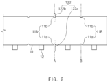
- the notching groove 11 comprises a first notching groove 11a and a second notching groove 11b, which are respectively formed in both surfaces of the electrode sheet 10 to face each other.
- first notching groove 11a and the second notching groove 11b are provided in plurality along a longitudinal direction of the electrode sheet 10.
- the plurality of first notching grooves 11a and the plurality of second notching grooves 11b are formed at regular intervals in the longitudinal direction of the electrode sheet 10 and have a triangular shape to accurately indicate a cutting position.
- the electrode sheet 10 having the above structure may be cut at a position at which the notching groove 11 is disposed so as to be manufactured as unit electrodes 1.
- the electrode sheet 10 is cut by using an apparatus for cutting the electrode sheet.
- the apparatus for cutting the electrode sheet may cut the electrode sheet 10 through the notching groove 11 formed in the electrode sheet 10 to improve current accuracy, thereby continuously manufacturing the unit electrodes 1 having uniform quality.
- an apparatus 100 for cutting an electrode sheet is an apparatus for cutting an electrode assembly through detection of a notching groove formed in a side surface of the electrode sheet and comprises a transfer unit 110 transferring an electrode sheet 10 in which a plurality of notching grooves 11 are formed at regular intervals in a side surface thereof, a detection unit 120 detecting the notching grooves 11 formed in the electrode sheet 10 transferred by the transfer unit 110, and a cutting unit 130 cutting the electrode sheet 10 when the detection unit 120 detects the notching grooves 11 to manufacture unit electrodes 1.
- the transfer unit 110 transfers the electrode sheet 10, in which the notching grooves 11 are formed, up to a cutting point B via a measuring point A.
- the transfer unit 110 transfers the electrode sheet 10 so that when the notching groove (hereinafter, referred to a front notching groove 11B), which is disposed in a front end, of the notching grooves 11 formed in the electrode sheet 10 passes through the cutting point B, the notching groove (hereinafter, referred to as a rear notching groove 11A), which is disposed in a rear end of the front notching groove 1B, passes through the measuring point A.
- a front notching groove 11B which is disposed in a front end
- the notching groove hereinafter, referred to as a rear notching groove 11A
- the transfer unit 110 comprises a conveyor belt transferring the electrode sheet 10 so that the notching grooves 11 formed at the regular intervals in the side surface of the electrode sheet 10 sequentially pass through the measuring point A to be transferred up to the cutting point B.
- the conveyor belt is provided in a pair to support and transfer both surfaces of the electrode sheet 10 at the same time.
- the detection unit 120 detects the notching groove of the electrode sheet passing through the measuring point A to generate a notching groove detection signal and comprises a detection body 121 provided at the measuring point A and a line sensor 122 fixed to the detection body 121 to detect the notching groove 11 of the electrode sheet 10 passing through the measuring point A and thereby to generate the notching groove detection signal.
- the line sensor 122 is installed in a direction perpendicular to the transfer direction of the electrode sheet 10 to detect the notching groove 11 of the electrode sheet 10 passing through the measuring point A and thereby to generate the notching groove detection signal.
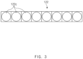
- the line sensor 122 comprises a plurality of light receiving elements 122c.
- the plurality of light receiving elements 122c detects the notching groove 11 through a variation in transmittance, which occurs when the notching groove 11 of the electrode sheet 10 passes through the measuring point A.
- the plurality of light receiving elements 122c are installed to be connected to each other in a direction that is perpendicular to the transfer direction of the electrode sheet 10, and the plurality of light receiving elements 122c have a predetermined transmittance while emitting light toward the electrode sheet 10.
- the plurality of light receiving elements irradiated toward the electrode sheet 10 varies in transmittance.
- the variation in transmittance may be calculated to detect the notching groove 11 of the electrode sheet 10.
- the line sensor 122 comprises first and second line sensors 122a and 122b detecting the first and second notching grooves 11a and 11b respectively formed in both surfaces of the electrode sheet 10 to face each other.
- the line sensor 122 comprising the first and second line sensors 122a and 122b may be set as follows.
- the line sensor 122 may generate the notching groove detection signal even though any one notching groove of the first and second notching grooves 11a and 11b is detected through the first and second line sensors 122a and 122b. That is, the sensor line 122 may generate the notching groove detection signal by being determined as the cutting time even though any one of the first and second notching grooves 11a and 11b is detected through the first and second line sensors 122a and 122b.
- the notching groove detection signal may be generated to improve continuity of the cutting operation.
- the line sensor 122 comprises the first and second line sensors 122a and 122b.
- the notching groove detection signal may be generated, and simultaneously, a defective signal may be generated with respect to the notching groove that is not detected. Accordingly, it is possible to be controlled so that a unit sheet having the notching groove, in which the defect signal is generated, is not provided for a method for manufacturing an electrode assembly.
- the line sensor 122 When all the first and second notching grooves 11a and 11b are detected through the first and second line sensors 122a and 122b, the line sensor 122 generates a notching groove detection signal as a mean value of a time at which the first notching groove 11a is detected and a time at which the second notching groove 11b is detected.
- the line sensor 122 determines this state as normal to generate the notching groove detection signal.
- the line sensor 122 this state as abnormal to generate the defective signal and simultaneously generate a signal for stopping the transfer part 110 so that the electrode sheet 10 is not transferred.
- the set value may be set to a value of 2.0 mm or less, preferably, 1.0 mm or less. That is, when the set value is set to the value of 2.0 mm or less, a cut surface having a 'v'-shaped groove is formed in one of the unit electrodes while a portion spaced apart by at least 1 mm from a vertex of each of the first notching groove 11a and the second notching groove 11b is cut. Particularly, a front end of the 'v'-shaped groove protrudes outward to the outside by 1 mm or more and thus is classified as a defective unit electrode.
- one cut surface of the cut unit electrode is formed to a size of 1 mm or less even though the 'v'-shaped groove is formed in the one cut surface of the cut unit electrode.
- the cut unit electrode is classified as a normal unit electrode.
- the line sensor 122 determines that a defect occurs in the electrode sheet 10 transferred by the transfer unit 110 to generate the notching groove defect signal and immediately to generate a stop signal to the transfer unit 110 so that the electrode sheet 10 is not transferred.
- the detection unit 120 may use the line sensor 122.
- the detection unit 12 may detect the notching groove 11 formed in the electrode sheet 10 and also generate the notching groove detection signal to accurately determine the cutting time of the electrode sheet 10.
- the first line sensor 122a detecting the first notching groove 11a may also detect whether the electrode tab 12 is defective through the variation in transmittance, which occurs when the electrode tab 12 formed on the electrode tab 10 passes. That is, the first line sensor 122a may detect a predetermined transmittance when the electrode tab 12 formed on the electrode sheet 10 passes. Here, when a portion or whole of the electrode tab 12 is folded or cut, an irregular variation of the transmittance may occur. Here, the first line sensor 122a may detect the irregular variation to determine whether the electrode tab is defective. Therefore, whether the electrode tab is defective may be confirmed without a separate additional detection sensor.
- the cutting unit 130 may be provided at the cutting point B to cut the electrode sheet 10, in which the notching groove passing through the cutting point B is disposed, according to the notching groove detection signal generated by the detection unit 120. Thus, the unit electrode 1 may be obtained.
- the cutting unit 130 detects the notching groove 11 passing through the measuring point A, the cutting unit 130 cuts the electrode sheet 10 in which the notching groove 11 passing through the cutting point B is disposed.
- the electrode sheet 10 may be cut through the detection of the notching groove 11 formed in the electrode sheet 10.
- the cutting time of the electrode sheet may be accurately detected to accurately cut the electrode sheet, thereby obtain the unit electrodes having the uniform quality.
- a method for cutting an electrode sheet comprises a step (a) of continuously transferring an electrode sheet 10, in which a plurality of notching grooves 11 are formed in a side surface at regular intervals, up to a cutting point B via a measuring point A, a step (b) of detecting the notching groove 11 of the electrode sheet 10 passing through the measuring point A to generate a notching groove detection signal, and a step (c) of cutting the electrode sheet 10, in which the notching groove 11 passing through the cutting point B is disposed, when the notching groove detection signal is generated, to manufacture a unit electrode 1.
- the electrode sheet 10 in which the plurality of notching grooves 11 are formed in the side surface thereof at the regular interval may be continuously transferred up to the cutting point B via the measuring point A by using the transfer unit 110.
- the electrode sheet 10 is transferred so that a rear notching groove 11A disposed at a rear end of the front notching groove 11A passes through the measuring point.
- the detection unit 120 detects the notching groove 11 of the electrode sheet 10 passing through the measuring point A to generate the notching groove detection signal.
- the detection part 120 comprises a line sensor 122, which is installed in a direction perpendicular to the transfer direction of the electrode sheet 10 to detect the notching groove 11 of the electrode sheet 10 passing through the measuring point A, thereby generating a notching groove detection signal.
- the line sensor 122 comprises a plurality of light receiving elements 122c. The plurality of light receiving elements 122c detects the notching groove 11 through a variation in transmittance, which occurs when the notching groove 11 of the electrode sheet 10 passes through the measuring point A.
- the line sensor 122 comprises first and second line sensors 122a and 122b detecting the first and second notching grooves 11a and 11b, which are respectively formed in both side surfaces of the electrode sheet 10, to generate the notching groove detection signal.
- the line sensor 122 may generate the notching groove detection signal even though any one of the first and second notching grooves 11a and 11b is detected through the first and second line sensors 122a and 122b. That is, even though any one of the first and second notching grooves 11a and 11b is detected through the first and second line sensors 122a and 122b, the line sensor 122 may generate the notching groove detection signal by detecting the detected notching groove as the cutting point.
- the line sensor 122 When all the first and second notching grooves 11a and 11b are detected through the first and second line sensors 122a and 122b, the line sensor 122 generates the notching groove detection signal as a mean value of a time at which the first notching groove 11a is detected and a time at which the second notching groove 11b is detected.
- the line sensor 122 determines that a defect occurs in the electrode sheet 10 transferred by the transfer unit 110 to generate a notching groove defect signal and immediately stop the transfer unit 110 so that the transfer of the electrode sheet 10 is stopped.
- the step (b) further comprises a step of detecting whether an electrode tab is defective through the variation in transmittance, which occurs when the electrode tab disposed on one surface of the electrode sheet passes, by using the detection unit.
- the electrode sheet 10 in which the notching groove 11 passing through the cutting point B is disposed is cut by using the cutting unit 130 to manufacture a unit electrodes 1.
- the unit electrodes 1 having uniform quality may be continuously manufactured through the method for cutting the electrode sheet according to the first embodiment of the present invention.
- the detection unit 120 is installed at the measuring point A.
- the apparatus 100' for cutting the electrode sheet further comprises an adjusting unit 140 installed to be movable in a direction perpendicular to the transfer direction of the electrode sheet 10.
- the adjusting part 140 may allow the detection unit 120 to move in the direction perpendicular to the transfer direction of the electrode sheet 10, and thus, may adjust a position of the detection unit 120 to correspond to the notching groove 11 passing through the measuring point A, thereby more accurately detecting the notching groove 11.
- the adjusting unit 140 may be installed at the measuring point A.
- a guide groove 141 may be formed in a top surface thereof facing the electrode sheet 10 in the direction perpendicular to the transfer direction of the electrode sheet 10.
- the detection unit 120 may be movably installed in the guide groove 141 to allow the detection unit 120 to move in the direction perpendicular to the transfer direction of the electrode sheet 10.
- the apparatus 100' for cutting the electrode sheet according to the second embodiment of the present invention may further comprise the adjusting unit 140.
- the detection unit 120 may be adjustable according to the position of the notching groove 11 of the electrode sheet so that the electrode sheets having various sizes and shapes are interconvertibly used.
Landscapes
- Engineering & Computer Science (AREA)
- Life Sciences & Earth Sciences (AREA)
- Forests & Forestry (AREA)
- Mechanical Engineering (AREA)
- Manufacturing & Machinery (AREA)
- Chemical & Material Sciences (AREA)
- Chemical Kinetics & Catalysis (AREA)
- Electrochemistry (AREA)
- General Chemical & Material Sciences (AREA)
- Battery Electrode And Active Subsutance (AREA)
Claims (8)
- Vorrichtung zum Schneiden eines Elektrodenblechs (10), die Vorrichtung umfassend:eine Transfereinheit (110), welche das Elektrodenblech (10), in welchem eine Mehrzahl von Kerbnuten (11) in einer Seitenfläche davon gebildet sind, bis zu einem Schneidepunkt (B) über einen Messpunkt (A) derart transferiert, dass wenn die Kerbnut (11), welche an einem vorderen Ende angeordnet ist, aus den Kerbnuten (11), welche in dem Elektrodenblech (10) gebildet sind, durch den Schneidepunkt (B) hindurchtritt, die Kerbnut (11), welche in einem hinteren Ende der vorderen Kerbnut (11) angeordnet ist, durch den Messpunkt (A) hindurchtritt;eine Detektionseinheit (120), welche an dem Messpunkt (A) bereitgestellt ist, um die Kerbnut (11) des Elektrodenblechs (10) zu detektieren, welche durch den Messpunkt (B) hindurchtritt, wobei ein Kerbnut (11)-Detektionssignal erzeugt wird; undeine Schneideeinheit (130), welche an dem Schneidepunkt (B) bereitgestellt ist, um das Elektrodenblech (10), in welchem die durch den Schneidepunkt (B) hindurchtretende Kerbnut (11) angeordnet ist, gemäß dem Kerbnut (11)-Detektionssignal zu schneiden, welches durch die Detektionseinheit (120) erzeugt wird;wobei die Detektionseinheit (120) einen Liniensensor (122) umfasst, welcher in einer Richtung senkrecht zu einer Transferrichtung des Elektrodenblechs (10) installiert ist, um die Kerbnut (11) des durch den Messpunkt (A) hindurchtretenden Elektrodenblechs (10) zu detektieren und dabei das Kerbnut (11)-Detektionssignal zu erzeugen,wobei der Liniensensor (122) eine Mehrzahl von Licht-Empfangselementen (122c) umfasst,wobei die Mehrzahl von Licht-Empfangselementen (122c) die Kerbnut (11) durch eine Variation in einem Transmissionsvermögen detektiert, welche auftritt, wenn die Kerbnut (11) des Elektrodenblechs (10) durch den Messpunkt (A) hindurchtritt;wobei die Kerbnut (11) erste und zweite Kerbnuten (11a) (11b) umfasst, welche jeweils in beiden Seitenflächen des Elektrodenblechs (10) gebildet sind, um zueinander zu weisen, undder Liniensensor (122) erste und zweite Liniensensoren (122a, 122b) umfasst, um die ersten und zweiten Kerbnuten (11a, 11b) zu detektieren.
- Vorrichtung nach Anspruch 1, wobei der Liniensensor (122) das Kerbnut (11)-Detektionssignal erzeugt, selbst eine beliebige aus der ersten und zweiten Kerbnut (11a, 11b) durch die ersten und zweiten Liniensensoren (122a, 122b) detektiert wird.
- Vorrichtung nach Anspruch 1, wobei wenn alle aus den ersten und zweiten Kerbnuten (11a, 11b) durch die ersten und zweiten Liniensensoren (122a, 122b) detektiert werden, der Liniensensor (122) das Kerbnut (11)-Detektionssignal als einen Mittelwert einer Zeit erzeugt, zu welcher die erste Kerbnut (11a) detektiert wird, und einer Zeit, zu welcher die zweite Kerbnut (11b) detektiert wird.
- Vorrichtung nach Anspruch 1, wobei wenn alle aus den ersten und zweiten Kerbnuten (11a, 11b) nicht durch die ersten und zweiten Kerbnuten (11a, 11b) detektiert werden, der Liniensensor (122) ein Kerbnuten (11)-Defektsignal erzeugt.
- Vorrichtung nach Anspruch 1, wobei ein Elektrodenstreifen an einer Fläche des Elektrodenblechs (10) bereitgestellt ist, in welcher die erste Kerbnut (11a) gebildet ist, und
der erste Liniensensor (122a), welcher die erste Kerbnut (11a) detektiert, ebenfalls durch die Variation in einem Transmissionsvermögen, welche auftritt, wenn der Elektrodenstreifen (12) hindurchtritt, detektiert, ob der Elektrodenstreifen (12) einen Defekt aufweist. - Vorrichtung nach Anspruch 1, wobei die Detektionseinheit (120) an dem Messpunkt (A) installiert ist, und
die Vorrichtung ferner eine Einstelleinheit (140) umfasst, welche dazu installiert ist, in einer Richtung senkrecht zu der Transferrichtung des Elektrodenblechs (10) bewegbar zu sein, so dass die Detektionseinheit (120) in einer Position eingestellt wird, um der Kerbnut (11) zu entsprechen, welche durch den Messpunkt (A) hindurchtritt. - Verfahren zum Schneiden eines Elektrodenblechs (10) unter Verwendung der Vorrichtung nach einem der Ansprüche 1 bis 6, das Verfahren umfassend:einen Schritt (a) eines kontinuierlichen Transferierens des Elektrodenblechs (10), in welchem eine Mehrzahl von Kerbnuten (11) in einer Seitenfläche davon gebildet sind, bis zu einem Schneidepunkt B über einen Messpunkt (A) durch Verwenden einer Transfereinheit (110), so dass, wenn die Kerbnut (11), welche an einem vorderen Ende angeordnet ist, aus den in dem Elektrodenblech (10) gebildeten Kerbnuten (11) durch den Schneidepunkt (B) hindurchtritt, die Kerbnut (11), welche in einem hinteren Ende der vorderen Kerbnut angeordnet ist, (11B) durch den Messpunkt (A) hindurchtritt;einen Schritt (b) eines Detektierens der Kerbnut (11) des Elektrodenblechs (10), welche durch den Messpunkt (A) hindurchtritt, um ein Kerbnut (11)-Detektionssignal zu erzeugen,einen Schritt (c) eines Schneidens des Elektrodenblechs (10), in welchem die durch einen Schneidepunkt (B) hindurchtretende Kerbnut (11) angeordnet ist, durch Verwenden einer Schneideeinheit (130), wenn ein Kerbnut (11)-Detektionssignal erzeugt wird, um eine Einheitselektrode herzustellen.
- Verfahren nach Anspruch 7, wobei der Schritt (b) ferner einen Schritt eines Detektierens umfasst, ob eine Elektrodenstreifen (12) einen Defekt aufweist, durch eine Variation in einem Transmissionsvermögen, welche auftritt, wenn der Elektrodenstreifen (12), welcher an einer Fläche des Elektrodenblechs (10) angeordnet ist, hindurchtritt, durch Verwendung einer Detektionseinheit (120).
Applications Claiming Priority (2)
| Application Number | Priority Date | Filing Date | Title |
|---|---|---|---|
| KR1020180051716A KR102341464B1 (ko) | 2018-05-04 | 2018-05-04 | 전극시트 커팅장치 및 커팅방법 |
| PCT/KR2018/014640 WO2019212112A1 (ko) | 2018-05-04 | 2018-11-26 | 전극시트 커팅장치 및 커팅방법 |
Publications (3)
| Publication Number | Publication Date |
|---|---|
| EP3633767A1 EP3633767A1 (de) | 2020-04-08 |
| EP3633767A4 EP3633767A4 (de) | 2020-08-19 |
| EP3633767B1 true EP3633767B1 (de) | 2023-09-06 |
Family
ID=68386594
Family Applications (1)
| Application Number | Title | Priority Date | Filing Date |
|---|---|---|---|
| EP18917080.6A Active EP3633767B1 (de) | 2018-05-04 | 2018-11-26 | Elektrodenblechschneidvorrichtung und schneidverfahren |
Country Status (5)
| Country | Link |
|---|---|
| US (1) | US11597115B2 (de) |
| EP (1) | EP3633767B1 (de) |
| KR (1) | KR102341464B1 (de) |
| CN (1) | CN110832676B (de) |
| WO (1) | WO2019212112A1 (de) |
Families Citing this family (18)
| Publication number | Priority date | Publication date | Assignee | Title |
|---|---|---|---|---|
| JP6563469B2 (ja) * | 2017-12-15 | 2019-08-21 | 本田技研工業株式会社 | 電極接合方法及び電極接合装置 |
| CN111180650A (zh) * | 2020-01-06 | 2020-05-19 | 深圳市海目星激光智能装备股份有限公司 | 极耳成型方法及成型装置 |
| CN111283267A (zh) * | 2020-03-20 | 2020-06-16 | 山东宏匀纳米科技有限公司 | 一种极片切割方法 |
| KR102662000B1 (ko) | 2020-07-14 | 2024-05-02 | 주식회사 엘지에너지솔루션 | 전극롤 연결 자동화 장치 |
| KR102721748B1 (ko) | 2020-07-14 | 2024-10-25 | 주식회사 엘지에너지솔루션 | 전극 커팅장치 및 커팅방법, 그를 포함하는 전극 제조설비 |
| KR20220008631A (ko) * | 2020-07-14 | 2022-01-21 | 주식회사 엘지에너지솔루션 | 전극 연결 장치 및 이를 이용한 전극 연결 자동화 방법 |
| US20230158701A1 (en) * | 2020-07-14 | 2023-05-25 | Lg Energy Solution, Ltd. | Electrode Cutting Device and Method and Electrode Manufacturing Apparatus Comprising the Same |
| ES3015081T3 (en) * | 2021-01-11 | 2025-04-29 | Lg Energy Solution Ltd | Electrode connecting apparatus and method, and notching equipment comprising same |
| CN116250109A (zh) * | 2021-01-12 | 2023-06-09 | 株式会社Lg新能源 | 一种电极制造装置以及使用电极制造装置的制造方法 |
| KR102611154B1 (ko) * | 2021-06-30 | 2023-12-11 | 주식회사 디에스케이 | 이차 전지용 전극시트 연결방법 |
| KR102593244B1 (ko) | 2021-08-13 | 2023-10-25 | 주식회사 엘지에너지솔루션 | 전극 위치 추적시스템 |
| KR20230046501A (ko) | 2021-09-30 | 2023-04-06 | 주식회사 엘지에너지솔루션 | 전극시트 커팅장치 및 커팅방법 |
| KR20230090720A (ko) * | 2021-12-15 | 2023-06-22 | 주식회사 엘지에너지솔루션 | 전극시트 커팅장치 및 커팅방법 |
| WO2023133809A1 (zh) * | 2022-01-14 | 2023-07-20 | 宁德时代新能源科技股份有限公司 | 极片错位控制方法、装置、极片、电芯、电池 |
| KR20230123372A (ko) * | 2022-02-16 | 2023-08-23 | 주식회사 엘지에너지솔루션 | 이차전지 제조장치 및 이를 이용하는 이차전지 제조방법 |
| CN114473249B (zh) * | 2022-03-29 | 2023-03-24 | 楚能新能源股份有限公司 | 一种极片模切方法及系统 |
| KR20240109708A (ko) | 2023-01-05 | 2024-07-12 | 심상헌 | 오정렬 보정 스플라인 커플링 유니트 |
| JP2025015928A (ja) * | 2023-07-21 | 2025-01-31 | 株式会社日立ハイテク | 二次電池用部材の欠陥検査装置、欠陥検査システム、欠陥検査プログラム、および、欠陥検査方法 |
Family Cites Families (44)
| Publication number | Priority date | Publication date | Assignee | Title |
|---|---|---|---|---|
| US4436008A (en) * | 1982-04-05 | 1984-03-13 | Pako Corporation | Photographic film web cutter and method |
| DE3236845C2 (de) * | 1982-10-05 | 1984-07-26 | Geimuplast Peter Mundt Gmbh & Co Kg, 8105 Farchant | Verfahren zum automatischen Schneiden von Filmstreifen |
| US4555968A (en) * | 1984-06-07 | 1985-12-03 | Preco Industries, Inc. | Web fed die cutting press having automatic 3-axis die registration system |
| US4697485A (en) * | 1986-04-16 | 1987-10-06 | Preco Industries, Inc. | Die press having 3-axis registration system operable during material advancement |
| JP2529959B2 (ja) * | 1987-03-09 | 1996-09-04 | バブコツク日立株式会社 | 板状触媒の連続製造装置 |
| DE3903133A1 (de) * | 1988-02-04 | 1989-08-31 | Amada Co | Werkstueckbearbeitbarkeitsdetektionsverfahren und verfahren zum spanabhebenden bearbeiten eines werkstuecks mit hilfe einer spanabhebenden bearbeitungsmaschine unter anwendung dieses verfahrens |
| JP2956928B2 (ja) | 1995-07-06 | 1999-10-04 | ソマール株式会社 | フィルム張付装置におけるフィルム先端処理方法及び装置 |
| US6202524B1 (en) * | 1996-09-24 | 2001-03-20 | Billco Manufacturing, Inc. | Glass workpiece locating system |
| JP3553417B2 (ja) * | 1999-05-14 | 2004-08-11 | 松下電器産業株式会社 | 電池用電極の製造方法 |
| JP4527844B2 (ja) * | 2000-05-10 | 2010-08-18 | パナソニック株式会社 | 電池用電極板の製造方法 |
| WO2002001656A2 (de) * | 2000-06-29 | 2002-01-03 | Wolfgang Kollmann | Verfahren zur herstellung von kathoden und anoden für elektrochemische systeme sowie ein dabei verwendeter metallisierter stoff, verfahren und vorrichtung zu dessen herstellung |
| JP2002033098A (ja) * | 2000-07-18 | 2002-01-31 | Nisshinbo Ind Inc | 電極用原反のスリッタ及び切断方法 |
| US6550362B1 (en) * | 2000-10-25 | 2003-04-22 | Si Corporation | Apparatus and method for dispensing fibers into cementitious materials |
| KR100478599B1 (ko) | 2002-12-26 | 2005-03-28 | 주식회사 에스엠시 | 배터리 셀 니켈단자 자동커팅장치 |
| JP3754420B2 (ja) * | 2003-02-04 | 2006-03-15 | 三洋電機株式会社 | 二次電池用電極板及びその製造方法並びにこの電極板を用いた二次電池 |
| JP2005277064A (ja) * | 2004-03-24 | 2005-10-06 | Tdk Corp | 電極の製造方法及び電極、並びに、電気化学デバイスの製造方法及び電気化学デバイス |
| KR100976717B1 (ko) * | 2005-01-25 | 2010-08-19 | 가부시키가이샤 아이에이치아이 | 전지 전극판 성형설비 |
| JP4995462B2 (ja) * | 2005-04-12 | 2012-08-08 | パナソニック株式会社 | 電池用電極板の製造方法 |
| KR100824808B1 (ko) | 2006-08-25 | 2008-04-24 | 주식회사 엘티케이 | 리튬 2차 전지용 전극 탭 자동검사기 |
| KR20080058772A (ko) * | 2006-12-22 | 2008-06-26 | 에스케이에너지 주식회사 | 전지용 전극의 제조 방법 |
| JP5337366B2 (ja) * | 2007-10-22 | 2013-11-06 | 本田技研工業株式会社 | 電池製造方法及び電池 |
| KR101420476B1 (ko) * | 2008-09-02 | 2014-07-16 | 도요타지도샤가부시키가이샤 | 전극 시트의 제조 방법 및 그 장치 |
| JP5461267B2 (ja) * | 2010-03-26 | 2014-04-02 | 三菱重工業株式会社 | 電極板製造装置、及び電極板製造方法 |
| JP5383571B2 (ja) * | 2010-03-26 | 2014-01-08 | 三菱重工業株式会社 | 電極板製造装置 |
| JP5308425B2 (ja) * | 2010-11-05 | 2013-10-09 | 三菱重工業株式会社 | 電池 |
| KR101271492B1 (ko) * | 2010-12-02 | 2013-06-05 | 주식회사 엘지화학 | 신규한 전극시트 커팅 장치 및 이를 사용하여 생산되는 이차전지 |
| KR101326628B1 (ko) | 2010-12-02 | 2013-11-07 | 주식회사 엘지화학 | 신규한 노칭 장치 및 이를 사용하여 생산되는 이차전지 |
| JP5579588B2 (ja) * | 2010-12-16 | 2014-08-27 | 株式会社日立ハイテクノロジーズ | 欠陥観察方法及びその装置 |
| JP5997876B2 (ja) * | 2011-04-07 | 2016-09-28 | 株式会社京都製作所 | 電池用電極部材搬送装置およびその方法 |
| TWI473329B (zh) * | 2011-04-07 | 2015-02-11 | Nissan Motor | Electrode manufacturing apparatus for battery and method thereof |
| KR101561445B1 (ko) | 2012-03-16 | 2015-10-21 | 주식회사 엘지화학 | 신규한 구조의 전극 제조장치 |
| KR101479723B1 (ko) * | 2012-07-06 | 2015-01-08 | 유일에너테크(주) | 2차 전지용 전극 생산 시스템 및 피딩장치 |
| DE102012109434A1 (de) * | 2012-10-04 | 2014-04-24 | Groz-Beckert Kg | Verfahren und Werkzeugeinheit zur Einstellung eines Stanzspalts |
| JP6142525B2 (ja) * | 2012-12-25 | 2017-06-07 | 日産自動車株式会社 | 電極位置検出装置 |
| CN203218383U (zh) | 2013-03-06 | 2013-09-25 | 万向电动汽车有限公司 | 一种电池极片叠片装置 |
| KR101509208B1 (ko) | 2013-07-03 | 2015-04-10 | 주식회사 엠플러스 | 이차 전지용 극판 치수 보정 장치 |
| TWI618131B (zh) * | 2013-08-30 | 2018-03-11 | 半導體能源研究所股份有限公司 | 剝離起點形成裝置及形成方法、疊層體製造裝置 |
| KR101479724B1 (ko) | 2013-11-25 | 2015-01-08 | 유일에너테크(주) | 2차 전지 전극용 고속 생산 시스템 |
| KR20160001353A (ko) * | 2014-06-27 | 2016-01-06 | 현대제철 주식회사 | 강판 폭 절단기의 캘리브레이션 장치 및 방법 |
| US9409306B2 (en) * | 2014-07-31 | 2016-08-09 | Usnr, Llc | Dynamically directed workpiece positioning system |
| KR101726785B1 (ko) * | 2014-11-03 | 2017-04-13 | 주식회사 엘지화학 | 스티치 커팅부를 포함하는 전극조립체 제조장치 및 이를 사용하여 제조된 전극조립체 |
| JP2016216186A (ja) | 2015-05-20 | 2016-12-22 | 株式会社豊田自動織機 | 加工装置 |
| CN104907711B (zh) | 2015-06-24 | 2017-11-21 | 中山汉通激光设备有限公司 | 一种电池极片激光切割头 |
| KR102246631B1 (ko) * | 2017-07-10 | 2021-04-30 | 주식회사 엘지화학 | 리튬 금속 전극용 3d 패턴 타발기 |
-
2018
- 2018-05-04 KR KR1020180051716A patent/KR102341464B1/ko active Active
- 2018-11-26 CN CN201880043574.3A patent/CN110832676B/zh active Active
- 2018-11-26 US US16/629,502 patent/US11597115B2/en active Active
- 2018-11-26 WO PCT/KR2018/014640 patent/WO2019212112A1/ko not_active Ceased
- 2018-11-26 EP EP18917080.6A patent/EP3633767B1/de active Active
Also Published As
| Publication number | Publication date |
|---|---|
| CN110832676A (zh) | 2020-02-21 |
| WO2019212112A1 (ko) | 2019-11-07 |
| KR102341464B1 (ko) | 2021-12-22 |
| US11597115B2 (en) | 2023-03-07 |
| EP3633767A4 (de) | 2020-08-19 |
| CN110832676B (zh) | 2022-09-16 |
| US20200139569A1 (en) | 2020-05-07 |
| EP3633767A1 (de) | 2020-04-08 |
| KR20190127283A (ko) | 2019-11-13 |
Similar Documents
| Publication | Publication Date | Title |
|---|---|---|
| EP3633767B1 (de) | Elektrodenblechschneidvorrichtung und schneidverfahren | |
| EP3621140B1 (de) | Vorrichtung und verfahren zur herstellung einer sekundärbatterie | |
| US20110102809A1 (en) | Apparatus detecting a position of a functional layer on an electrode | |
| EP4026651B1 (de) | Schweissqualitätsprüfvorrichtung | |
| WO2010082335A1 (ja) | 塗工膜の幅の検査方法および該検査方法に用いる検査装置 | |
| KR102558461B1 (ko) | 전극조립체의 제조방법 및 제조장치 | |
| KR102900762B1 (ko) | 와전류 센서를 이용한 전지 셀의 균열 검사 시스템 | |
| KR101789854B1 (ko) | 이차전지 사행 불량 판정 시스템 및 그 방법 | |
| KR20220060880A (ko) | 전지 셀의 균열 검사를 위한 와전류 센서 및 이를 포함하는 전지 셀의 균열 검출 시스템 | |
| ES3055767T3 (en) | Method and device for testing electrode sheet | |
| KR20230070867A (ko) | 이차전지 압연 시스템 및 이를 이용한 이차전지 불량 예측 방법 | |
| EP4270572B1 (de) | Elektrodenblatt-schneidvorrichtung und schneidverfahren | |
| KR100696811B1 (ko) | 이차전지의 전극롤 권취 방법 | |
| JP2014078448A (ja) | エッジ検出方法 | |
| KR20230046501A (ko) | 전극시트 커팅장치 및 커팅방법 | |
| KR20200114407A (ko) | 전극 너울 측정방법 및 전극 너울 측정장치 | |
| KR102920808B1 (ko) | 분리막 통기도 검사장치 및 이를 이용한 분리막 통기도 검사방법 | |
| KR20220167204A (ko) | 용접 상태 검사 장치 및 검사 방법 | |
| EP4353401A1 (de) | Vorrichtung und verfahren zur prüfung des schweisszustands | |
| KR102741592B1 (ko) | 전지의 판정 방법 | |
| KR20230161844A (ko) | 사행 보정 장치 및 사행 보정 방법 | |
| US20250003733A1 (en) | Device and Method for Measuring Sealing Gap for Secondary Battery | |
| US20250058486A1 (en) | Notching Device and Control Method Therefor | |
| CN121844198A (zh) | 用于对电极接头进行检查的设备和方法 | |
| KR20250056508A (ko) | 방향표시부가 구비된 매거진 및 이를 포함하는 이차전지 제조장치 |
Legal Events
| Date | Code | Title | Description |
|---|---|---|---|
| STAA | Information on the status of an ep patent application or granted ep patent |
Free format text: STATUS: THE INTERNATIONAL PUBLICATION HAS BEEN MADE |
|
| PUAI | Public reference made under article 153(3) epc to a published international application that has entered the european phase |
Free format text: ORIGINAL CODE: 0009012 |
|
| STAA | Information on the status of an ep patent application or granted ep patent |
Free format text: STATUS: REQUEST FOR EXAMINATION WAS MADE |
|
| 17P | Request for examination filed |
Effective date: 20191230 |
|
| AK | Designated contracting states |
Kind code of ref document: A1 Designated state(s): AL AT BE BG CH CY CZ DE DK EE ES FI FR GB GR HR HU IE IS IT LI LT LU LV MC MK MT NL NO PL PT RO RS SE SI SK SM TR |
|
| AX | Request for extension of the european patent |
Extension state: BA ME |
|
| A4 | Supplementary search report drawn up and despatched |
Effective date: 20200716 |
|
| RIC1 | Information provided on ipc code assigned before grant |
Ipc: H01M 10/04 20060101ALI20200710BHEP Ipc: H01M 4/04 20060101AFI20200710BHEP Ipc: B26F 1/12 20060101ALI20200710BHEP Ipc: B26D 5/34 20060101ALI20200710BHEP |
|
| DAV | Request for validation of the european patent (deleted) | ||
| DAX | Request for extension of the european patent (deleted) | ||
| RAP1 | Party data changed (applicant data changed or rights of an application transferred) |
Owner name: LG ENERGY SOLUTION LTD. |
|
| RAP3 | Party data changed (applicant data changed or rights of an application transferred) |
Owner name: LG ENERGY SOLUTION, LTD. |
|
| GRAP | Despatch of communication of intention to grant a patent |
Free format text: ORIGINAL CODE: EPIDOSNIGR1 |
|
| STAA | Information on the status of an ep patent application or granted ep patent |
Free format text: STATUS: GRANT OF PATENT IS INTENDED |
|
| RIC1 | Information provided on ipc code assigned before grant |
Ipc: B26D 5/32 20060101ALI20230427BHEP Ipc: B26D 1/08 20060101ALI20230427BHEP Ipc: B26F 1/12 20060101ALI20230427BHEP Ipc: B26D 5/34 20060101ALI20230427BHEP Ipc: H01M 10/04 20060101ALI20230427BHEP Ipc: H01M 4/04 20060101AFI20230427BHEP |
|
| INTG | Intention to grant announced |
Effective date: 20230531 |
|
| GRAS | Grant fee paid |
Free format text: ORIGINAL CODE: EPIDOSNIGR3 |
|
| GRAA | (expected) grant |
Free format text: ORIGINAL CODE: 0009210 |
|
| STAA | Information on the status of an ep patent application or granted ep patent |
Free format text: STATUS: THE PATENT HAS BEEN GRANTED |
|
| P01 | Opt-out of the competence of the unified patent court (upc) registered |
Effective date: 20230706 |
|
| AK | Designated contracting states |
Kind code of ref document: B1 Designated state(s): AL AT BE BG CH CY CZ DE DK EE ES FI FR GB GR HR HU IE IS IT LI LT LU LV MC MK MT NL NO PL PT RO RS SE SI SK SM TR |
|
| REG | Reference to a national code |
Ref country code: GB Ref legal event code: FG4D |
|
| REG | Reference to a national code |
Ref country code: CH Ref legal event code: EP |
|
| REG | Reference to a national code |
Ref country code: IE Ref legal event code: FG4D |
|
| REG | Reference to a national code |
Ref country code: DE Ref legal event code: R096 Ref document number: 602018057292 Country of ref document: DE |
|
| REG | Reference to a national code |
Ref country code: LT Ref legal event code: MG9D |
|
| REG | Reference to a national code |
Ref country code: NL Ref legal event code: MP Effective date: 20230906 |
|
| PG25 | Lapsed in a contracting state [announced via postgrant information from national office to epo] |
Ref country code: GR Free format text: LAPSE BECAUSE OF FAILURE TO SUBMIT A TRANSLATION OF THE DESCRIPTION OR TO PAY THE FEE WITHIN THE PRESCRIBED TIME-LIMIT Effective date: 20231207 |
|
| PG25 | Lapsed in a contracting state [announced via postgrant information from national office to epo] |
Ref country code: SE Free format text: LAPSE BECAUSE OF FAILURE TO SUBMIT A TRANSLATION OF THE DESCRIPTION OR TO PAY THE FEE WITHIN THE PRESCRIBED TIME-LIMIT Effective date: 20230906 Ref country code: RS Free format text: LAPSE BECAUSE OF FAILURE TO SUBMIT A TRANSLATION OF THE DESCRIPTION OR TO PAY THE FEE WITHIN THE PRESCRIBED TIME-LIMIT Effective date: 20230906 Ref country code: NO Free format text: LAPSE BECAUSE OF FAILURE TO SUBMIT A TRANSLATION OF THE DESCRIPTION OR TO PAY THE FEE WITHIN THE PRESCRIBED TIME-LIMIT Effective date: 20231206 Ref country code: LV Free format text: LAPSE BECAUSE OF FAILURE TO SUBMIT A TRANSLATION OF THE DESCRIPTION OR TO PAY THE FEE WITHIN THE PRESCRIBED TIME-LIMIT Effective date: 20230906 Ref country code: LT Free format text: LAPSE BECAUSE OF FAILURE TO SUBMIT A TRANSLATION OF THE DESCRIPTION OR TO PAY THE FEE WITHIN THE PRESCRIBED TIME-LIMIT Effective date: 20230906 Ref country code: HR Free format text: LAPSE BECAUSE OF FAILURE TO SUBMIT A TRANSLATION OF THE DESCRIPTION OR TO PAY THE FEE WITHIN THE PRESCRIBED TIME-LIMIT Effective date: 20230906 Ref country code: GR Free format text: LAPSE BECAUSE OF FAILURE TO SUBMIT A TRANSLATION OF THE DESCRIPTION OR TO PAY THE FEE WITHIN THE PRESCRIBED TIME-LIMIT Effective date: 20231207 Ref country code: FI Free format text: LAPSE BECAUSE OF FAILURE TO SUBMIT A TRANSLATION OF THE DESCRIPTION OR TO PAY THE FEE WITHIN THE PRESCRIBED TIME-LIMIT Effective date: 20230906 |
|
| REG | Reference to a national code |
Ref country code: AT Ref legal event code: MK05 Ref document number: 1609722 Country of ref document: AT Kind code of ref document: T Effective date: 20230906 |
|
| PG25 | Lapsed in a contracting state [announced via postgrant information from national office to epo] |
Ref country code: NL Free format text: LAPSE BECAUSE OF FAILURE TO SUBMIT A TRANSLATION OF THE DESCRIPTION OR TO PAY THE FEE WITHIN THE PRESCRIBED TIME-LIMIT Effective date: 20230906 |
|
| PG25 | Lapsed in a contracting state [announced via postgrant information from national office to epo] |
Ref country code: IS Free format text: LAPSE BECAUSE OF FAILURE TO SUBMIT A TRANSLATION OF THE DESCRIPTION OR TO PAY THE FEE WITHIN THE PRESCRIBED TIME-LIMIT Effective date: 20240106 |
|
| PG25 | Lapsed in a contracting state [announced via postgrant information from national office to epo] |
Ref country code: AT Free format text: LAPSE BECAUSE OF FAILURE TO SUBMIT A TRANSLATION OF THE DESCRIPTION OR TO PAY THE FEE WITHIN THE PRESCRIBED TIME-LIMIT Effective date: 20230906 |
|
| PG25 | Lapsed in a contracting state [announced via postgrant information from national office to epo] |
Ref country code: ES Free format text: LAPSE BECAUSE OF FAILURE TO SUBMIT A TRANSLATION OF THE DESCRIPTION OR TO PAY THE FEE WITHIN THE PRESCRIBED TIME-LIMIT Effective date: 20230906 |
|
| PG25 | Lapsed in a contracting state [announced via postgrant information from national office to epo] |
Ref country code: SM Free format text: LAPSE BECAUSE OF FAILURE TO SUBMIT A TRANSLATION OF THE DESCRIPTION OR TO PAY THE FEE WITHIN THE PRESCRIBED TIME-LIMIT Effective date: 20230906 Ref country code: RO Free format text: LAPSE BECAUSE OF FAILURE TO SUBMIT A TRANSLATION OF THE DESCRIPTION OR TO PAY THE FEE WITHIN THE PRESCRIBED TIME-LIMIT Effective date: 20230906 Ref country code: IS Free format text: LAPSE BECAUSE OF FAILURE TO SUBMIT A TRANSLATION OF THE DESCRIPTION OR TO PAY THE FEE WITHIN THE PRESCRIBED TIME-LIMIT Effective date: 20240106 Ref country code: ES Free format text: LAPSE BECAUSE OF FAILURE TO SUBMIT A TRANSLATION OF THE DESCRIPTION OR TO PAY THE FEE WITHIN THE PRESCRIBED TIME-LIMIT Effective date: 20230906 Ref country code: EE Free format text: LAPSE BECAUSE OF FAILURE TO SUBMIT A TRANSLATION OF THE DESCRIPTION OR TO PAY THE FEE WITHIN THE PRESCRIBED TIME-LIMIT Effective date: 20230906 Ref country code: CZ Free format text: LAPSE BECAUSE OF FAILURE TO SUBMIT A TRANSLATION OF THE DESCRIPTION OR TO PAY THE FEE WITHIN THE PRESCRIBED TIME-LIMIT Effective date: 20230906 Ref country code: AT Free format text: LAPSE BECAUSE OF FAILURE TO SUBMIT A TRANSLATION OF THE DESCRIPTION OR TO PAY THE FEE WITHIN THE PRESCRIBED TIME-LIMIT Effective date: 20230906 Ref country code: PT Free format text: LAPSE BECAUSE OF FAILURE TO SUBMIT A TRANSLATION OF THE DESCRIPTION OR TO PAY THE FEE WITHIN THE PRESCRIBED TIME-LIMIT Effective date: 20240108 Ref country code: SK Free format text: LAPSE BECAUSE OF FAILURE TO SUBMIT A TRANSLATION OF THE DESCRIPTION OR TO PAY THE FEE WITHIN THE PRESCRIBED TIME-LIMIT Effective date: 20230906 |
|
| PG25 | Lapsed in a contracting state [announced via postgrant information from national office to epo] |
Ref country code: PL Free format text: LAPSE BECAUSE OF FAILURE TO SUBMIT A TRANSLATION OF THE DESCRIPTION OR TO PAY THE FEE WITHIN THE PRESCRIBED TIME-LIMIT Effective date: 20230906 Ref country code: IT Free format text: LAPSE BECAUSE OF FAILURE TO SUBMIT A TRANSLATION OF THE DESCRIPTION OR TO PAY THE FEE WITHIN THE PRESCRIBED TIME-LIMIT Effective date: 20230906 |
|
| REG | Reference to a national code |
Ref country code: DE Ref legal event code: R097 Ref document number: 602018057292 Country of ref document: DE |
|
| REG | Reference to a national code |
Ref country code: CH Ref legal event code: PL |
|
| PG25 | Lapsed in a contracting state [announced via postgrant information from national office to epo] |
Ref country code: MC Free format text: LAPSE BECAUSE OF FAILURE TO SUBMIT A TRANSLATION OF THE DESCRIPTION OR TO PAY THE FEE WITHIN THE PRESCRIBED TIME-LIMIT Effective date: 20230906 |
|
| PG25 | Lapsed in a contracting state [announced via postgrant information from national office to epo] |
Ref country code: DK Free format text: LAPSE BECAUSE OF FAILURE TO SUBMIT A TRANSLATION OF THE DESCRIPTION OR TO PAY THE FEE WITHIN THE PRESCRIBED TIME-LIMIT Effective date: 20230906 |
|
| PLBE | No opposition filed within time limit |
Free format text: ORIGINAL CODE: 0009261 |
|
| STAA | Information on the status of an ep patent application or granted ep patent |
Free format text: STATUS: NO OPPOSITION FILED WITHIN TIME LIMIT |
|
| PG25 | Lapsed in a contracting state [announced via postgrant information from national office to epo] |
Ref country code: LU Free format text: LAPSE BECAUSE OF NON-PAYMENT OF DUE FEES Effective date: 20231126 |
|
| PG25 | Lapsed in a contracting state [announced via postgrant information from national office to epo] |
Ref country code: CH Free format text: LAPSE BECAUSE OF NON-PAYMENT OF DUE FEES Effective date: 20231130 |
|
| PG25 | Lapsed in a contracting state [announced via postgrant information from national office to epo] |
Ref country code: MC Free format text: LAPSE BECAUSE OF FAILURE TO SUBMIT A TRANSLATION OF THE DESCRIPTION OR TO PAY THE FEE WITHIN THE PRESCRIBED TIME-LIMIT Effective date: 20230906 Ref country code: LU Free format text: LAPSE BECAUSE OF NON-PAYMENT OF DUE FEES Effective date: 20231126 Ref country code: DK Free format text: LAPSE BECAUSE OF FAILURE TO SUBMIT A TRANSLATION OF THE DESCRIPTION OR TO PAY THE FEE WITHIN THE PRESCRIBED TIME-LIMIT Effective date: 20230906 Ref country code: CH Free format text: LAPSE BECAUSE OF NON-PAYMENT OF DUE FEES Effective date: 20231130 Ref country code: SI Free format text: LAPSE BECAUSE OF FAILURE TO SUBMIT A TRANSLATION OF THE DESCRIPTION OR TO PAY THE FEE WITHIN THE PRESCRIBED TIME-LIMIT Effective date: 20230906 |
|
| REG | Reference to a national code |
Ref country code: BE Ref legal event code: MM Effective date: 20231130 |
|
| 26N | No opposition filed |
Effective date: 20240607 |
|
| REG | Reference to a national code |
Ref country code: IE Ref legal event code: MM4A |
|
| PG25 | Lapsed in a contracting state [announced via postgrant information from national office to epo] |
Ref country code: IE Free format text: LAPSE BECAUSE OF NON-PAYMENT OF DUE FEES Effective date: 20231126 |
|
| PG25 | Lapsed in a contracting state [announced via postgrant information from national office to epo] |
Ref country code: BE Free format text: LAPSE BECAUSE OF NON-PAYMENT OF DUE FEES Effective date: 20231130 |
|
| PG25 | Lapsed in a contracting state [announced via postgrant information from national office to epo] |
Ref country code: IE Free format text: LAPSE BECAUSE OF NON-PAYMENT OF DUE FEES Effective date: 20231126 Ref country code: BE Free format text: LAPSE BECAUSE OF NON-PAYMENT OF DUE FEES Effective date: 20231130 |
|
| PG25 | Lapsed in a contracting state [announced via postgrant information from national office to epo] |
Ref country code: BG Free format text: LAPSE BECAUSE OF FAILURE TO SUBMIT A TRANSLATION OF THE DESCRIPTION OR TO PAY THE FEE WITHIN THE PRESCRIBED TIME-LIMIT Effective date: 20230906 |
|
| PG25 | Lapsed in a contracting state [announced via postgrant information from national office to epo] |
Ref country code: BG Free format text: LAPSE BECAUSE OF FAILURE TO SUBMIT A TRANSLATION OF THE DESCRIPTION OR TO PAY THE FEE WITHIN THE PRESCRIBED TIME-LIMIT Effective date: 20230906 |
|
| PG25 | Lapsed in a contracting state [announced via postgrant information from national office to epo] |
Ref country code: CY Free format text: LAPSE BECAUSE OF FAILURE TO SUBMIT A TRANSLATION OF THE DESCRIPTION OR TO PAY THE FEE WITHIN THE PRESCRIBED TIME-LIMIT; INVALID AB INITIO Effective date: 20181126 |
|
| PG25 | Lapsed in a contracting state [announced via postgrant information from national office to epo] |
Ref country code: HU Free format text: LAPSE BECAUSE OF FAILURE TO SUBMIT A TRANSLATION OF THE DESCRIPTION OR TO PAY THE FEE WITHIN THE PRESCRIBED TIME-LIMIT; INVALID AB INITIO Effective date: 20181126 |
|
| PG25 | Lapsed in a contracting state [announced via postgrant information from national office to epo] |
Ref country code: TR Free format text: LAPSE BECAUSE OF FAILURE TO SUBMIT A TRANSLATION OF THE DESCRIPTION OR TO PAY THE FEE WITHIN THE PRESCRIBED TIME-LIMIT Effective date: 20230906 |
|
| PGFP | Annual fee paid to national office [announced via postgrant information from national office to epo] |
Ref country code: DE Payment date: 20251020 Year of fee payment: 8 |
|
| PGFP | Annual fee paid to national office [announced via postgrant information from national office to epo] |
Ref country code: GB Payment date: 20251023 Year of fee payment: 8 |
|
| PGFP | Annual fee paid to national office [announced via postgrant information from national office to epo] |
Ref country code: FR Payment date: 20251021 Year of fee payment: 8 |