EP3631086B1 - Rail assembly for rail vehicles having flanged wheels - Google Patents
Rail assembly for rail vehicles having flanged wheels Download PDFInfo
- Publication number
- EP3631086B1 EP3631086B1 EP18737145.5A EP18737145A EP3631086B1 EP 3631086 B1 EP3631086 B1 EP 3631086B1 EP 18737145 A EP18737145 A EP 18737145A EP 3631086 B1 EP3631086 B1 EP 3631086B1
- Authority
- EP
- European Patent Office
- Prior art keywords
- rail
- profile
- filling element
- leg
- profile leg
- Prior art date
- Legal status (The legal status is an assumption and is not a legal conclusion. Google has not performed a legal analysis and makes no representation as to the accuracy of the status listed.)
- Active
Links
- 239000000463 material Substances 0.000 claims description 17
- 239000007787 solid Substances 0.000 claims description 12
- 238000010276 construction Methods 0.000 claims description 4
- 239000013536 elastomeric material Substances 0.000 claims description 3
- 239000000945 filler Substances 0.000 description 13
- 239000002184 metal Substances 0.000 description 8
- 238000012423 maintenance Methods 0.000 description 6
- 230000008439 repair process Effects 0.000 description 5
- XLYOFNOQVPJJNP-UHFFFAOYSA-N water Substances O XLYOFNOQVPJJNP-UHFFFAOYSA-N 0.000 description 5
- 244000043261 Hevea brasiliensis Species 0.000 description 3
- 238000004140 cleaning Methods 0.000 description 3
- 238000009434 installation Methods 0.000 description 3
- 229920003052 natural elastomer Polymers 0.000 description 3
- 229920001194 natural rubber Polymers 0.000 description 3
- 238000004026 adhesive bonding Methods 0.000 description 2
- 230000001066 destructive effect Effects 0.000 description 2
- 238000009413 insulation Methods 0.000 description 2
- 239000004033 plastic Substances 0.000 description 2
- 229920003023 plastic Polymers 0.000 description 2
- 239000005062 Polybutadiene Substances 0.000 description 1
- 229910000831 Steel Inorganic materials 0.000 description 1
- 239000000853 adhesive Substances 0.000 description 1
- 230000001070 adhesive effect Effects 0.000 description 1
- 229920005549 butyl rubber Polymers 0.000 description 1
- 229920001577 copolymer Polymers 0.000 description 1
- 238000013016 damping Methods 0.000 description 1
- 238000005553 drilling Methods 0.000 description 1
- 230000003670 easy-to-clean Effects 0.000 description 1
- 229920001971 elastomer Polymers 0.000 description 1
- 239000003292 glue Substances 0.000 description 1
- 238000000227 grinding Methods 0.000 description 1
- 238000004519 manufacturing process Methods 0.000 description 1
- 238000003801 milling Methods 0.000 description 1
- 239000000203 mixture Substances 0.000 description 1
- 229920000642 polymer Polymers 0.000 description 1
- 239000004810 polytetrafluoroethylene Substances 0.000 description 1
- 229920001343 polytetrafluoroethylene Polymers 0.000 description 1
- 229920002635 polyurethane Polymers 0.000 description 1
- 239000004814 polyurethane Substances 0.000 description 1
- 230000001681 protective effect Effects 0.000 description 1
- 239000005060 rubber Substances 0.000 description 1
- 239000002689 soil Substances 0.000 description 1
- 239000011343 solid material Substances 0.000 description 1
- 239000010959 steel Substances 0.000 description 1
- 229920003048 styrene butadiene rubber Polymers 0.000 description 1
- 230000007704 transition Effects 0.000 description 1
Images


Classifications
-
- E—FIXED CONSTRUCTIONS
- E01—CONSTRUCTION OF ROADS, RAILWAYS, OR BRIDGES
- E01B—PERMANENT WAY; PERMANENT-WAY TOOLS; MACHINES FOR MAKING RAILWAYS OF ALL KINDS
- E01B15/00—Guards for preventing a person's foot being trapped in grooved rails
-
- E—FIXED CONSTRUCTIONS
- E01—CONSTRUCTION OF ROADS, RAILWAYS, OR BRIDGES
- E01B—PERMANENT WAY; PERMANENT-WAY TOOLS; MACHINES FOR MAKING RAILWAYS OF ALL KINDS
- E01B21/00—Track superstructure adapted for tramways in paved streets
-
- E—FIXED CONSTRUCTIONS
- E01—CONSTRUCTION OF ROADS, RAILWAYS, OR BRIDGES
- E01B—PERMANENT WAY; PERMANENT-WAY TOOLS; MACHINES FOR MAKING RAILWAYS OF ALL KINDS
- E01B21/00—Track superstructure adapted for tramways in paved streets
- E01B21/02—Special supporting means; Draining of rails
-
- E—FIXED CONSTRUCTIONS
- E01—CONSTRUCTION OF ROADS, RAILWAYS, OR BRIDGES
- E01C—CONSTRUCTION OF, OR SURFACES FOR, ROADS, SPORTS GROUNDS, OR THE LIKE; MACHINES OR AUXILIARY TOOLS FOR CONSTRUCTION OR REPAIR
- E01C9/00—Special pavings; Pavings for special parts of roads or airfields
- E01C9/04—Pavings for railroad level-crossings
Definitions
- the invention relates to a rail arrangement for rail vehicles with flange wheels, in particular in the area of track coverings and track crossings, and the use of a filler profile for this purpose.
- grooved rails with a running rail, a guardrail and a groove in between are often used, the groove accommodating the flange of a flange wheel of rail vehicles equipped with it, e.g. trams, and the guardrail primarily as derailment protection and to protect against undesired narrowing of the Groove, for example by driving over with road vehicles, is used.
- Grooved rails are for example from the DE 102004018914 A1 , DE 102004054794 B3 , DE 202004017132 U1 , DE 202005004107 U1 , DE 479362 , DE 499056 , DE 608258 , DE 812674 , DE 564508 and EP 1462570 A1 known.
- the groove is a potential source of danger for road users such as cyclists, whose tires can get caught in the groove, or for pedestrians, for example women with high heels or old people. Efforts have therefore already been made in the prior art to at least minimize the danger emanating from the groove.
- a protective insert preferably made of plastic, for example foamed polyurethane
- From the DE 87 07 445 U1 It is also known to fix a filler profile made of rubber or rubber-like material in the groove by means of retaining lips and gluing.
- DE 29509395 U1 and the EP 0830480 describes guide devices for grooved rails in the area of turnouts, in which parts of the device take over the guardrail function.
- the object of the present invention is therefore to provide a rail arrangement for rail vehicles with flange wheels in the area of, for example, track coverings and track crossings, which other road users such as motor vehicles and bicycles can safely drive on, but which is comparatively inexpensive and easy to maintain or repair .
- the rail arrangement according to the invention is comparatively simple in structure and, because it is not attached to the rail, does not require any special design or changes to an existing rail, for example drilling holes in the rail web.
- the arrangement can be laid together with the rail or afterwards. It is easy to clean, for example by machine.
- the use of a grooved rail or other tracking devices attached to the rail is not necessary, since the cover and the generally L- / J-shaped angle profile attached to it assume the function of the groove and the guardrail or the track guidance.
- the cover is detachably attached to the support structure, for example screwed on, and can be removed if necessary, for example for maintenance or repair purposes, in order to enable access to the space beneath the cover next to the rail.
- the generally L- / J-shaped angle profile is firmly connected to the cover, it can be reversibly removed from the supporting structure together with the cover.
- the rail is thus completely accessible in a simple manner, so that the invention also facilitates machine rail grinding (reprofiling).
- the rail arrangement according to the invention can also be safely passed or driven on by other vehicles, in particular for motor vehicles and bicycles, and can also be safely walked on by pedestrians.
- the filling profile can be removed from the supporting structure together with the cover. This is particularly easy in embodiments in which the profile is attached to the angle profile in a suitable manner.
- Vehicle rail type rail includes not only Vignole rails but also crane rails and refers to rails with a rail foot, a rail web and a rail head that does not have a groove that serves as a channel for the flange of a flange wheel.
- the term also includes grooved rails or areas of Grooved rails in which the guardrail and thus the groove has been technically removed, for example by milling.
- L- or J-shaped angle profile includes isosceles or non-isosceles angle profiles, the legs not necessarily having to be at an exactly right angle to one another and also being able to run in an arc.
- a leg of the L- / J-shaped angle profile running in the direction of the rail foot this means a section of the angle profile running essentially vertically or parallel to the rail web, while when referring to a leg of the L- / J-shaped angle profile means an essentially horizontal, possibly curved section of the angle profile which is oriented towards the rail.
- reversibly detachable in relation to the cover means that the cover can be removed in an essentially non-destructive manner and can be reattached to the original position. This can mean, for example, that the cover is only placed in place and is essentially not attached. However, this preferably means that the cover can be fastened to the supporting structure, for example by means of a screw connection, and can be detached from it again. “Essentially non-destructive” in this context means that neither the supporting structure nor the cover are damaged when the cover is removed.
- reversibly removable therefore also includes that the cover is fastened to the supporting structure by means of an adhesive which must be replaced when the cover is re-attached.
- guardrail also guide rail, auxiliary rail or catch rail refers to a guide that usually runs within the rails of a track, and is part of grooved rails.
- filling profile denotes a preferably elastically deformable profile that can be introduced into a groove or groove-like structure.
- a filler profile is preferably designed in such a way that it has suitable damping properties, i.e. is elastically deformed when loaded by the wheel flange being driven over and is simultaneously deformed as little as possible by motor vehicles, bicycles etc. passing over it.
- the rail arrangement according to the invention comprises a strand-like filling profile, the filling profile being arranged on the second leg running in the direction of the rail web.
- “Strand-shaped” means that the filling profile forms an elongated profile strand so that it can be laid parallel to a rail.
- the surface of the filling profile is essentially aligned with the running surface of the rail head.
- an essentially flat surface is formed next to the rail, so that, for example, bicycles do not get into the groove with their wheels.
- the filling profile is attached to the generally L- or J-shaped angle profile, for example by screwing or gluing.
- the filling profile is generally L- or J-shaped in cross section and has a first profile leg running in the direction of the rail foot and a second profile leg running in the direction of the rail web, the first profile leg containing at least one hollow channel running in the longitudinal direction of the strand-like filling profile, which is surrounded transversely to the longitudinal direction of the strand-like filling profile by profile material, and the second profile leg of the filling profile is solid and forms a filling profile base.
- “Solid” in this context means that there are no hollow channels, but that the profile leg is made of solid material.
- the first and second profile legs are preferably made of the same, preferably elastomeric, material, but they can also consist of different materials.
- the second profile leg forming the profile base is preferably harder, ie less elastically deformable, than the first profile leg, which is elastically deformed in the vertical direction when driven over by a flange wheel, but then returns to its starting position.
- the part of the first profile leg which is located at its free end and which is most exposed to wear due to flanged wheels being driven over can optionally be coated or reinforced.
- the second profile leg preferably extends over the entire width of the groove in this area and rests over the entire surface of the second leg of the angle profile.
- the support structure has a rear wall extending essentially parallel to the longitudinal direction of the rail and transverse walls directed transversely thereto in the direction of the rail and arranged at intervals from one another.
- the supporting structure is preferably arranged on a base plate, which can for example consist of metal, for example steel, and is preferably fastened, for example by means of welded connections. Ribbed plates for rail fastening, for example, can also be arranged on this base plate.
- the supporting structure can have openings or perforations, preferably in the transverse walls and / or in the floor area. This makes machine cleaning and drainage easier.
- the supporting structure has a drainage connection.
- This is preferably arranged in the area of the base of the supporting structure and enables efficient drainage or suction of water, for example in the case of heavy rainfall or cleaning.
- the cover can for example be a metal plate which preferably has openings in order to fasten the cover to the supporting structure by means of suitable fastening devices, e.g. screw connections, and to prevent water deposits.
- the invention also provides the use of a filler profile for a rail arrangement according to the invention, the filler profile being designed in the form of a strand and a generally L- or J-shaped Having cross section, and wherein a first profile leg contains at least one hollow channel running in the longitudinal direction of the strand-like filling profile, which is surrounded by profile material transversely to the longitudinal direction of the strand-like filling profile, and a second profile leg of the filling profile is solid.
- the solid second profile leg preferably serves as a profile base.
- the first leg has a section with a projection that protrudes in the direction in which the second profile leg extends, with at least part of the at least one hollow channel being located in the section with the projection.
- Projecting here means in particular that the projection extends beyond an imaginary perpendicular, precipitated from the projection-side corner of the free end of the first profile leg onto the second profile leg.
- the section with the projection is arranged such that the projection can be brought into engagement in the installation situation with the rail head underside of a rail of the Vignole rail type.
- the projection is attached at a distance from the free end of the first profile leg which corresponds to the rail head height of a rail of the Vignole rail type or slightly exceeds it.
- the profile material laterally surrounding the at least one hollow channel in the first profile leg forms a first side profile leg wall facing the side with the second profile leg and an opposite second side profile leg wall, the first lateral profile leg wall running in a zigzag shape in cross section in that the projection is formed, the inner wall surfaces of the at least one hollow channel in the section with the projection running towards the first lateral profile leg wall essentially parallel to the outer wall surfaces of the first lateral profile leg wall, so that the first lateral profile leg wall in the section with the projection has essentially the same, ie an essentially uniform, wall thickness.
- a single hollow channel is arranged in the first profile leg so that the wall part facing the free end of the first profile leg has a greater wall thickness than the first lateral profile leg wall, and the second lateral profile leg wall also has a zigzag cross-section the inner wall surfaces of the one hollow channel in the section with the projection run essentially parallel to the respective outer wall surfaces of the first and second lateral profile leg wall, so that the first and second lateral profile leg walls in the section with the projection have essentially a uniform wall thickness .
- the filling profile is particularly preferably designed to be generally L-shaped in cross section.
- the filling profile consists of an elastomeric material.
- Suitable elastomeric materials are, for example, those based on styrene-butadiene rubber (SBR), natural rubber (NR), a natural rubber-butyl rubber mixture (NR / BR) or ethylene-propylene-diene copolymer (EPDM).
- SBR styrene-butadiene rubber
- NR natural rubber
- NR / BR natural rubber-butyl rubber mixture
- EPDM ethylene-propylene-diene copolymer
- the two profile legs can be formed from the same or different materials. It is also possible that a profile leg consists of different materials.
- the wall area lying at the free end of the first profile leg can comprise a harder material, for example metal, or be coated, for example with a PTFE layer.
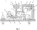
- FIG. 1 shows a cross section through an embodiment of a rail arrangement 1 according to the invention.
- the rail arrangement 1 comprises a rail 2 of the Vignole rail type with a rail head 3 having a running surface 6, a rail web 4 and a rail foot 5.
- the rail 2 is arranged here on a metal ribbed plate 14.
- An insulation layer 12 is arranged between the underside of the rail foot 5 and the ribbed plate 14, which insulation layer can consist of a plastic polymer, for example.
- the surface of the rib plate 14 has a slight incline, so that the rail 2 arranged thereon is also slightly inclined. If the rail 2 is part of a track, it is inclined slightly towards the inside of the track.
- the rail 2 is fixed on the ribbed plate 14 in a known manner with the aid of tension clamps 15.
- the rib plate 14 is fixed here on a base plate 16, for example welded in place.
- the base plate 16 has fastening devices 17 with the aid of which it can be fastened, for example screwed, to a suitable surface, for example railway sleepers.
- a support structure 7 flanking the rail in the longitudinal direction is shown, which comprises a metal rear wall 13 running in the longitudinal direction of the rail with supports 18 welded to it and directed towards the rail 2.
- the supporting structure 7 also includes metal transverse walls 25 (see Sect. Figure 5A , B; Figure 6 ), which are welded to the rear wall 13 and extend transversely to the longitudinal direction of the rail in the direction of the rail 2.
- the support structure 7 would preferably flank the rail 2 towards the inside of the track.
- the support structure 7 is used to support a flat metal cover 9, which is so is designed so that it can be driven on by motor vehicles, for example.
- the cover 9 rests here on the supports 18 and the transverse walls 25 and is secured by means of on the transverse walls 25 (see FIG. Figure 5A ) provided mounting flanges 26 reversibly fastened with corresponding fastening devices 21, for example by means of screw connections.
- the cover 9 covers the spatial area 8 directly along the length of the rail 2.
- the upper surface of the cover 9 is essentially aligned with the running surface 6 of the rail 2 and has an edge region 11 directed towards the rail 2, which forms a guardrail or the function the guardrail of a grooved rail takes over.
- a metal angle profile 10, here in cross section, is fixedly attached, for example welded, to its underside.
- the L-shaped angle profile 10 comprises a first leg 19, which runs essentially vertically and extends in the direction of the rail foot 5, and a substantially horizontal second leg 20, which extends in the direction of the rail web 4.
- the second leg 20 is in the region of the rail web 4 arranged, ie the free end of the second leg 20 is below the level of the underside of the rail head 3 and above the rail foot 5, the free end of the second leg 20 preferably within the of the underside of the rail head 3, the rail web 4 and the top of the Rail foot 5 limited rail chamber 33 is located.
- the free end of the second leg 20 can reach up to the rail web 4 and even touch it, or it can be spaced from the rail web 4. Together with the edge area 11, the legs 19, 20 of the angle profile 10 and the lateral flanks of the rail 2 form a groove 28 in which, for example, a filler profile 100, 200, 220 can be arranged.
- the cover 9 is firmly connected to the angle profile 10 and can be removed from the support structure 7 together with the angle profile 10 and optionally the filler profile 100, 200, 220, for example to carry out maintenance or repair work.
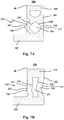
- Figure 2 shows a cross section through the in Figure 1 Shown embodiment of a rail arrangement 1 according to the invention with a strand-like filling profile 100, which is arranged on the second leg 20 of the angle profile 10 and here only has the function of recreating the groove bottom of a conventional groove rail and filling the space between angle profile 10 and rail 2.
- the filling profile 100 has a hollow channel 101 running in the longitudinal direction of the strand-like filling profile 100.
- FIG. shows a part of a flange wheel 22 with a flange 23 for illustration.
- the dashed line indicates the limits of a wheel flange 23 which protrudes further into the groove 28 due to the wear of the rail head 3.
- Figure 3 shows a cross section through the in Figure 1
- the filling profile 200 is generally L-shaped in cross section and has a first profile leg 202 extending essentially vertically in the direction of the rail foot 5 or in the direction of the open end of the groove 28 and a first profile leg 202 second profile leg 203 extending essentially horizontally.
- the first profile leg 202 here has two hollow channels 201 and is elastically deformable, so that the profile leg 202 is elastically deformed in the vertical direction when driven by the flange 23, while the second profile leg 203 is designed as a solid profile base and in comparison to the first profile leg 202 is not or only slightly elastically deformable.
- the second profile leg 203 is arranged on the second leg 20 of the angle profile 10, while the first profile leg 202 of the filler profile 200 rests on the one hand on the first leg 19 of the angle profile 10 and on the other hand against the side flank of the rail head 3 facing the groove 28.
- the first profile leg 202 is in a section 204 (see Sect. Figure 7A ) designed zigzag in cross-section.
- the profile leg 202 has an angularly shaped projection 206 which is arranged at the level of the underside of the rail head 3 or just below it, whereby the cross section of the profile leg 202 is expanded so that the profile leg 202 is wider than the groove 28 at this point in the area of the rail head 3 and the projection 206 is in engagement with the underside of the rail head 3.
- a hollow channel 201 with inner wall surfaces 209, 210 (see Sect. Figure 7A ) is designed in this section in cross-section as a square or diamond-shaped standing on a point, while a second, overlying hollow channel 201 is generally semicircular in cross-section, with an essentially horizontal or slightly arched inner wall towards the open end of the profile leg 202 .
- the profile material laterally surrounding the lower hollow channel 201 in the first profile leg 202 forms a first side profile leg wall 207 facing the side with the second profile leg 203 with an outer wall surface 211 and an opposing second side profile leg wall 208 with an outer one Wall area 212 (see p. Figure 7A ).
- the lateral profile leg wall 207 directed towards the rail 2 has essentially a uniform wall thickness in the section 204 with the projection 206.
- the solid part 205 of the profile leg 202 located at the upper free end has a greater wall thickness than the lateral profile leg wall 207 below.
- the filler profile 200 is here with the aid of a profile leg running through the first leg 19 of the angle profile 10 and into the second, solid profile leg 203 of the filling profile 200 protruding screw 24 attached to the angle profile 10.
- the cross section of the second profile leg 203 is as wide as the groove 28 and fills it in this area.
- Figure 4 shows a cross section through the in Figure 1
- the illustrated embodiment of a rail arrangement 1 according to the invention with a further strand-like filling profile 220 (for details see also Figure 7B ).
- This filling profile 220 is also generally L-shaped in cross section and has a first profile leg 222 extending essentially vertically in the direction of the rail foot 5 or in the direction of the open end of the groove 28 and a second profile leg 223 extending essentially horizontally.
- the first profile leg 222 here has only one hollow channel 221 and is elastically deformable, in particular in the direction of the groove bottom, while the second profile leg 223 forming the profile base is solid and comparatively hard and not very elastically deformable.
- the second profile leg 223 extends over the entire groove cross-section.
- the filling profile 220 is fastened to the angle profile 10 with the aid of a screw 24 screwed into the second profile leg 223 and can be removed together with the cover 9 and the angle profile 10 in one work step in order to make the spatial area 8 accessible alongside the rail 2 .
- both profile leg walls 227, 228 laterally surrounding the hollow channel 221 are designed in a zigzag shape in the section 224 with the projection 226 (see Fig. Figure 7B ).
- the projection 226 formed in the first profile leg wall 227 extends in the direction of the rail 2 and is in engagement with the underside of the rail head.
- the single hollow channel 221 is designed such that its lateral inner surfaces 229, 230 run essentially parallel to the respective lateral outer wall surfaces 231, 232 of the profile leg walls 227, 228, so that the lateral profile leg walls 227, 228 of the filling profile 220 in the area of the hollow channel 221 have a substantially uniform wall thickness.
- the solid one at the upper free end Part 225 of the profile leg 222 has a greater wall thickness than the lateral profile leg walls 227, 228 lying underneath.
- Figure 5 represents a simplified spatial view of a rail arrangement 1 according to the invention.
- Figure 5A shows the support structure 7 without the cover 9, Figure 5B with the cover 9.
- Clamps 15 are not shown here for the sake of clarity, as are the fastening devices 17 of the base plate. Only the bores 29 provided for this purpose are shown here. Only a section of the rail 2 is shown.
- Figure 5B For the sake of clarity, only a section of a cover 9 is also shown. From this view, transverse walls 25 can be seen which, starting from the rear wall 13, extend in the direction of the rail 2 and provide upper bearing surfaces 30 on which the cover 9 can be placed. If necessary, the angle profile 10 can be brought to rest with its second leg 20 on the lower-lying support surfaces 31 of the transverse walls 25.
- the transverse walls 25 have openings 32 which, for example, serve to drain off water.
- mounting flanges 26 are provided here on two transverse walls 25, via which the cover 9 can be fastened reversibly by means of suitable fastening devices 21, for example screw connections.
- the cover 9 here has openings 27 which can serve not only to fasten the cover 9 to the supporting structure 7 by means of fastening devices 21, but also to drain water from the inside of the track.
- the base plate 16 can have openings (not shown here) as drainage connections in order to drain or suck off water into the soil.
- Figure 6 shows a simplified plan view of an embodiment of a rail arrangement according to the invention 1.
- the cover 9 has been omitted for the sake of better clarity.
- the rib plates 14 are shown without tension clamps 15 and only the bores 29 for the fastening devices of the base plate 16. Otherwise, to avoid unnecessary repetition, refer to the description of the Figures 1 to 5 referenced.
- FIGS. 7A and 7B show embodiments of a filler profile 200, 220 designed according to the invention
- Figure 7A fill profile 200 was already shown at Figure 3 , this in Figure 7B shown filling profile Figure 4 so that reference is also made to the description there.
- Both filling profiles 200, 220 are made of elastomeric material and are designed in the form of strands. They have a generally L-shaped cross section, a first profile leg 202, 222 containing at least one hollow channel 201, 221 running in the longitudinal direction of the strand-like filling profile 200, 220, which is surrounded by profile material transversely to the longitudinal direction of the strand-like filling profile 200, 220.
- the hollow channel 201, 221 can be open to the end faces of the strand-like filling profile 200, 220, but is laterally surrounded by profile material so that a first profile leg wall 207, 227 and a second profile leg wall 208, 228 are formed.
- a second profile leg 203, 223 is solid and forms a comparatively hard profile base that is less elastically deformable than the first leg 202, 222.
- the first, more elastically deformable leg 202, 222 runs essentially vertically in the intended installation situation, while the second, less elastically deformable profile leg 203, 223 runs essentially horizontally.
- the filling profiles 200, 220 have a projection 206, 226 in the direction in which the second leg 203, 223 also extends, which extends over an imaginary perpendicular 40 that extends from the upper left corner of the filling profile 200, 220 in the figure the second profile leg 203, 223 is precipitated, protrudes horizontally.
- the course of the outer wall surfaces 211, 231 of the first profile leg 202, 222 in the section 204, 224 with the projection 206, 226 essentially follows the contour of the hollow channel 201, 221 located on the inside in this section 204, 224 At the in Figure 7B This also applies to the outer wall surfaces 232 of the second profile leg 222.
Description
Die Erfindung betrifft eine Schienenanordnung für Schienenfahrzeuge mit Spurkranzrädern, insbesondere im Bereich von Gleiseindeckungen und Gleisüberwegen sowie die Verwendung von einem Füllprofil hierfür.The invention relates to a rail arrangement for rail vehicles with flange wheels, in particular in the area of track coverings and track crossings, and the use of a filler profile for this purpose.
Schienenverkehrswege, die in Bereichen verlaufen, die auch von anderen Fahrzeugen, beispielsweise Kraftfahrzeugen und Fahrrädern, oder Fußgängern benutzt werden, müssen besonderen Anforderungen hinsichtlich des Übergangs zu der an die Schienen angrenzenden Eindeckung, beispielsweise einer Straße oder eines Gleisüberwegs, genügen. Dies gilt beispielsweise für den Fall von Straßenbahnschienen, die in oder auf von Kraftfahrzeugen, Fahrrädern und Fußgängern genutzten Straßen verlegt sind, aber auch für Haupt- oder Nebenbahnschienen beispielsweise im Bereich von Gleisüberwegen.Rail traffic routes that run in areas that are also used by other vehicles, for example motor vehicles and bicycles, or pedestrians, must meet special requirements with regard to the transition to the covering adjacent to the rails, for example a road or a track crossing. This applies, for example, to the case of tram tracks that are laid in or on roads used by motor vehicles, bicycles and pedestrians, but also to main or secondary tracks, for example in the area of railroad crossings.
Bei derartigen Schienenverkehrswegen werden häufig Rillenschienen mit einer Fahrschiene, einer Leitschiene und einer dazwischen liegenden Rille eingesetzt, wobei die Rille den Spurkranz eines Spurkranzrades von damit ausgestatteten Schienenfahrzeugen, z.B. Straßenbahnen, aufnimmt und die Leitschiene vor allem als Entgleisungsschutz und zum Schutz gegen eine ungewollte Verengung der Rille, beispielsweise durch das Überfahren mit Straßenfahrzeugen, dient. Rillenschienen sind beispielsweise aus der
Die Rille ist allerdings eine potenzielle Gefahrenquelle für Verkehrsteilnehmer wie z.B. Fahrradfahrer, deren Reifen sich in der Rille verfangen können, oder auch für Fußgänger, z.B. Frauen mit hohen Absätzen oder alte Menschen. Es sind daher im Stand der Technik bereits Bemühungen unternommen worden, die von der Rille ausgehende Gefahr zumindest zu minimieren. In der
Neben Sicherheitsaspekten spielt auch die Wartungsmöglichkeit von Schienenanordnungen im Bereich von Gleiseindeckungen und Gleisüberwegen eine wichtige Rolle. Es ist daher wünschenswert, Schienenanordnungen in diesem Bereich entsprechend so auszugestalten, dass regelmäßige Wartungen, beispielsweise Reinigungen, Reparaturen und Erneuerungen, möglichst einfach, schnell und unkompliziert durchgeführt werden können. Es wäre überdies wünschenswert, wenn auf Rillenschienen verzichtet werden könnte, die relativ aufwändig in der Herstellung und wartungsintensiv sind.In addition to safety aspects, the ability to maintain track arrangements in the area of track coverings and track crossings also plays an important role. It is therefore desirable to design rail arrangements in this area in such a way that regular maintenance, for example cleaning, repairs and renewals, can be carried out as simply, quickly and easily as possible. It would also be desirable if grooved rails could be dispensed with, which are relatively complex to manufacture and require a lot of maintenance.
In der
In der
Aus der
In der
Es besteht nach wie vor Bedarf, Schienenverkehrswege für Schienenfahrzeuge mit Spurkranzrädern im Bereich von beispielsweise Gleiseindeckungen und Gleisüberwegen hinsichtlich Kosten- Wartungs-, Instandsetzungs- und Sicherheitsaspekten zu verbessern.There is still a need to improve rail traffic routes for rail vehicles with flange wheels in the area of, for example, track coverings and track crossings with regard to cost, maintenance, repair and safety aspects.
Aufgabe der vorliegenden Erfindung ist es daher, eine Schienenanordnung für Schienenfahrzeuge mit Spurkranzrädern im Bereich von beispielsweise Gleiseindeckungen und Gleisüberwegen bereit zu stellen, die sicher auch für andere Verkehrsteilnehmer wie Kraftfahrzeuge und Fahrräder befahrbar, dabei jedoch vergleichsweise kostengünstig und leicht zu warten oder instand zu setzen ist.The object of the present invention is therefore to provide a rail arrangement for rail vehicles with flange wheels in the area of, for example, track coverings and track crossings, which other road users such as motor vehicles and bicycles can safely drive on, but which is comparatively inexpensive and easy to maintain or repair .
Gelöst wird die Aufgabe durch die Gegenstände der unabhängigen Ansprüche. Zweckmäßige Ausgestaltungen der Erfindung sind in den Unteransprüchen angegeben.The problem is solved by the subjects of the independent claims. Appropriate refinements of the invention are given in the subclaims.
Die Erfindung stellte eine Schienenanordnung für Schienenfahrzeuge mit Spurkranzrädern, bereit, wobei die Schienenanordnung folgendes umfasst:
- a) mindestens eine Schiene vom Vignolschienentyp mit einem eine Lauffläche für ein Spurkranzrad aufweisenden Schienenkopf, einem Schienensteg und einem Schienenfuß
- b) eine die Schiene seitlich in Schienenlängsrichtung flankierende Tragkonstruktion für eine den räumlichen Bereich unmittelbar längsseitig der Schiene bedeckende Abdeckung, die
- aa) mit der Tragkonstruktion lösbar so verbunden ist, dass die Abdeckung in der Einbausituation von der Tragkonstruktion reversibel abnehmbar ist,
- bb) eine im Wesentlichen horizontale Oberfläche aufweist, die im Wesentlichen mit der Lauffläche des Schienenkopfes fluchtet, und
- cc) einen zur Schiene gerichteten Randbereich aufweist, der eine Leitschiene bildet,
- c) ein im Querschnitt allgemein L- oder J-förmiges Winkelprofil, das mit der Abdeckung fest verbunden oder damit einstückig ausgebildet ist, wobei das Winkelprofil einen ersten in Richtung Schienenfuß verlaufenden Schenkel und einen zweiten in Richtung Schienensteg verlaufenden Schenkel aufweist, und
- d) ein strangförmiges Füllprofil, wobei das Füllprofil auf dem zweiten in Richtung Schienensteg verlaufenden Schenkel angeordnet ist,
- a) at least one rail of the Vignole rail type with a rail head having a running surface for a flange wheel, a rail web and a rail foot
- b) a support structure flanking the rail laterally in the longitudinal direction of the rail for a cover covering the spatial area directly along the rail, which
- aa) is detachably connected to the supporting structure in such a way that the cover can be reversibly removed from the supporting structure in the installation situation,
- bb) has a substantially horizontal surface which is substantially flush with the running surface of the rail head, and
- cc) has an edge area directed towards the rail, which forms a guardrail,
- c) an angular profile generally L- or J-shaped in cross section, which is firmly connected to the cover or is formed in one piece therewith, the angular profile having a first leg extending in the direction of the rail foot and a second leg extending in the direction of the rail web, and
- d) a strand-like filling profile, wherein the filling profile is arranged on the second leg running in the direction of the rail web,
Die erfindungsgemäße Schienenanordnung ist vergleichsweise einfach im Aufbau und erfordert durch den Verzicht auf eine Befestigung an der Schiene keine besondere Ausgestaltung oder die Vornahme von Änderungen an einer vorhandenen Schiene, beispielsweise das Anbringen von Bohrungen im Schienensteg. Die Anordnung kann zusammen mit der Schiene oder auch nachträglich verlegt werden. Sie ist leicht, beispielsweise auch maschinell, zu reinigen. Der Einsatz einer Rillenschiene oder anderer an der Schiene befestigter Spurführungsvorrichtungen ist nicht erforderlich, da die Abdeckung und das daran befestigte allgemein L-/J-förmige Winkelprofil die Funktion der Rille und der Leitschiene bzw. die Spurführung übernehmen. Die Abdeckung ist abnehmbar an der Tragkonstruktion befestigt, beispielsweise angeschraubt, und kann bei Bedarf, beispielsweise zu Wartungs- oder Instandsetzungszwecken, abgenommen werden, um so den Zugang zu dem unter der Abdeckung liegenden Raum neben der Schiene zu ermöglichen. Da das allgemein L-/J-förmige Winkelprofil mit der Abdeckung fest verbunden ist, kann es zusammen mit der Abdeckung von der Tragkonstruktion reversibel entfernt werden. Die Schiene wird damit auf einfache Weise vollständig zugänglich, so dass die Erfindung auch ein maschinelles Schienenschleifen (Reprofiling) erleichtert.The rail arrangement according to the invention is comparatively simple in structure and, because it is not attached to the rail, does not require any special design or changes to an existing rail, for example drilling holes in the rail web. The arrangement can be laid together with the rail or afterwards. It is easy to clean, for example by machine. The use of a grooved rail or other tracking devices attached to the rail is not necessary, since the cover and the generally L- / J-shaped angle profile attached to it assume the function of the groove and the guardrail or the track guidance. The cover is detachably attached to the support structure, for example screwed on, and can be removed if necessary, for example for maintenance or repair purposes, in order to enable access to the space beneath the cover next to the rail. Since the generally L- / J-shaped angle profile is firmly connected to the cover, it can be reversibly removed from the supporting structure together with the cover. The rail is thus completely accessible in a simple manner, so that the invention also facilitates machine rail grinding (reprofiling).
Die erfindungsgemäße Schienenanordnung ist darüber hinaus für andere Fahrzeuge, insbesondere für Kraftfahrzeuge und Fahrräder sicher passier- bzw. befahrbar und auch sicher für Fußgänger begehbar. Darüber hinaus kann das Füllprofil gemeinsam mit der Abdeckung von der Tragkonstruktion abgenommen werden. Das ist besonders einfach in Ausführungsformen, bei denen das Profil in geeigneter Weise an dem Winkelprofil befestigt ist.The rail arrangement according to the invention can also be safely passed or driven on by other vehicles, in particular for motor vehicles and bicycles, and can also be safely walked on by pedestrians. In addition, the filling profile can be removed from the supporting structure together with the cover. This is particularly easy in embodiments in which the profile is attached to the angle profile in a suitable manner.
Der Begriff "Schiene vom Vignolschienentyp" schließt neben Vignolschienen auch Kranschienen ein und bezieht sich auf Schienen mit einem Schienenfuß, einem Schienensteg und einem Schienenkopf, der keine Rille aufweist, die als Spurkanal für den Spurkranz eines Spurkranzrades dient. Der Begriff schließt auch Rillenschienen bzw. Bereiche von Rillenschienen ein, bei denen die Leitschiene und damit die Rille technisch entfernt wurde, beispielsweise durch Abfräsen.The term "Vignole rail type rail" includes not only Vignole rails but also crane rails and refers to rails with a rail foot, a rail web and a rail head that does not have a groove that serves as a channel for the flange of a flange wheel. The term also includes grooved rails or areas of Grooved rails in which the guardrail and thus the groove has been technically removed, for example by milling.
Der Begriff "allgemein L- oder J-förmiges Winkelprofil" schließt gleichschenkelige oder nichtgleichschenkelige Winkelprofile ein, wobei die Schenkel nicht notwendig in einem exakt rechten Winkel zueinander stehen müssen und auch bogenförmig verlaufen können. Wenn hier auf einen in Richtung Schienenfuß verlaufenden Schenkel des L-/J-förmigen Winkelprofils Bezug genommen ist, ist damit ein im Wesentlichen vertikal oder parallel zum Schienensteg verlaufender Abschnitt des Winkelprofils gemeint, während bei Bezugnahme auf einen in Richtung Schienensteg verlaufenden Schenkel des L-/J-förmigen Winkelprofils ein im Wesentlichen horizontal, dabei gegebenenfalls bogenförmig ausgebildeter, zur Schiene hin ausgerichteter Abschnitt des Winkelprofils gemeint ist.The term “generally L- or J-shaped angle profile” includes isosceles or non-isosceles angle profiles, the legs not necessarily having to be at an exactly right angle to one another and also being able to run in an arc. When reference is made here to a leg of the L- / J-shaped angle profile running in the direction of the rail foot, this means a section of the angle profile running essentially vertically or parallel to the rail web, while when referring to a leg of the L- / J-shaped angle profile means an essentially horizontal, possibly curved section of the angle profile which is oriented towards the rail.
Der Ausdruck "reversibel abnehmbar" in Bezug auf die Abdeckung bedeutet, dass die Abdeckung im Wesentlichen zerstörungsfrei abnehmbar und an der ursprünglichen Position wieder anbringbar ist. Das kann beispielsweise bedeuten, dass die Abdeckung lediglich aufgelegt und im Wesentlichen nicht befestigt ist. Bevorzugt bedeutet dies aber, dass die Abdeckung beispielsweise mittels einer Schraubverbindung an der Tragkonstruktion befestigt und davon wieder gelöst werden kann. "Im Wesentlichen zerstörungsfrei" bedeutet in diesem Zusammenhang, dass weder die Tragkonstruktion noch die Abdeckung beim Abnehmen der Abdeckung beschädigt werden. Der Begriff "reversibel abnehmbar" schließt daher auch ein, dass die Abdeckung mittels eines Klebers an der Tragkonstruktion befestigt ist, der beim Wiederanbringen der Abdeckung erneuert werden muss.The term "reversibly detachable" in relation to the cover means that the cover can be removed in an essentially non-destructive manner and can be reattached to the original position. This can mean, for example, that the cover is only placed in place and is essentially not attached. However, this preferably means that the cover can be fastened to the supporting structure, for example by means of a screw connection, and can be detached from it again. “Essentially non-destructive” in this context means that neither the supporting structure nor the cover are damaged when the cover is removed. The term "reversibly removable" therefore also includes that the cover is fastened to the supporting structure by means of an adhesive which must be replaced when the cover is re-attached.
Der Ausdruck, wonach die Abdeckung "einen zur Schiene gerichteten Randbereich aufweist, der eine Leitschiene bildet" bedeutet, dass die Abdeckung an ihrem zur Schiene weisenden Randbereich so ausgebildet ist, dass die Abdeckung hier eine Führungsvorrichtung nach Art einer Leitschiene nachbildet bzw. als eine Art Leitschiene fungiert, wie sie ansonsten Bestandteil einer Rillenschiene ist. Hierzu kann die Abdeckung an ihrem zur Schiene gerichteten Rand eine gerade oder angeschrägte Kante aufweisen, an der ein Spurkranzrad mit dem Spurkranz entlang geführt werden kann. Der Ausdruck "Leitschiene" (auch Führungsschiene, Beischiene oder Fangschiene) bezieht sich auf eine Führung, die üblicherweise innerhalb der Fahrschienen eines Gleises verläuft, und Bestandteil von Rillenschienen ist.The expression, according to which the cover "has an edge area directed towards the rail, which forms a guardrail" means that the cover is designed at its edge area facing the rail so that the cover here simulates a guide device in the manner of a guardrail or as a kind Guard rail functions as it is otherwise part of a grooved rail. For this purpose, the cover can have a straight or beveled edge on its edge directed towards the rail, along which a flange wheel can be guided along with the flange. The term "guardrail" (also guide rail, auxiliary rail or catch rail) refers to a guide that usually runs within the rails of a track, and is part of grooved rails.
Der Begriff "Füllprofil" bezeichnet ein vorzugsweise elastisch verformbares Profil, das in eine Rille oder rillenartige Struktur eingebracht werden kann. Ein Füllprofil ist hinsichtlich seiner materiellen und elastischen Eigenschaften vorzugsweise so ausgestaltet, dass es geeignete Dämpfungseigenschaften aufweist, d.h. bei Belastung durch den überfahrenden Spurkranz elastisch verformt wird und gleichzeitig durch überfahrende Kraftfahrzeuge, Fahrräder etc. so wenig wie möglich verformt wird.The term "filling profile" denotes a preferably elastically deformable profile that can be introduced into a groove or groove-like structure. With regard to its material and elastic properties, a filler profile is preferably designed in such a way that it has suitable damping properties, i.e. is elastically deformed when loaded by the wheel flange being driven over and is simultaneously deformed as little as possible by motor vehicles, bicycles etc. passing over it.
Die erfindungsgemäße Schienenanordnung umfasst ein strangförmiges Füllprofil, wobei das Füllprofil auf dem zweiten in Richtung Schienensteg verlaufenden Schenkel angeordnet ist. "Strangförmig" bedeutet, dass das Füllprofil einen länglichen Profilstrang bildet, so dass es parallel zu einer Schiene verlegt werden kann.The rail arrangement according to the invention comprises a strand-like filling profile, the filling profile being arranged on the second leg running in the direction of the rail web. "Strand-shaped" means that the filling profile forms an elongated profile strand so that it can be laid parallel to a rail.
Das Füllprofil fluchtet in einer bevorzugten Ausführungsform mit seiner Oberfläche im Wesentlichen mit der Lauffläche des Schienenkopfes. Dadurch ist eine im Wesentlichen ebene Oberfläche neben der Schiene gebildet, so dass beispielsweise Fahrräder mit ihren Rädern nicht in die Rille geraten.In a preferred embodiment, the surface of the filling profile is essentially aligned with the running surface of the rail head. As a result, an essentially flat surface is formed next to the rail, so that, for example, bicycles do not get into the groove with their wheels.
Das Füllprofil ist an dem allgemein L- oder J-förmigen Winkelprofil befestigt, beispielsweise durch Verschrauben oder Verkleben.The filling profile is attached to the generally L- or J-shaped angle profile, for example by screwing or gluing.
Besonders bevorzugt ist das Füllprofil im Querschnitt allgemein L- oder J-förmig ausgebildet und weist einen ersten in Richtung Schienenfuß verlaufenden Profilschenkel und einen zweiten in Richtung Schienensteg verlaufenden Profilschenkel auf, wobei der erste Profilschenkel mindestens einen in Längsrichtung des strangförmigen Füllprofils verlaufenden Hohlkanal enthält, der quer zur Längsrichtung des strangförmigen Füllprofils von Profilmaterial umgeben ist, und der zweite Profilschenkel des Füllprofils solide ausgebildet ist und eine Füllprofilbasis bildet. "Solide" bedeutet in diesem Zusammenhang, dass keine Hohlkanäle vorhanden sind, sondern der Profilschenkel aus Vollmaterial besteht. Erster und zweiter Profilschenkel sind vorzugsweise aus demselben, vorzugsweise elastomeren, Material gefertigt, können aber auch aus unterschiedlichen Materialen bestehen. Der die Profilbasis bildende zweite Profilschenkel ist vorzugsweise härter, d.h. weniger elastisch verformbar als der erste Profilschenkel, der sich beim Überfahren durch ein Spurkranzrad elastisch in vertikaler Richtung verformt, anschließend jedoch wieder in die Ausgangsposition zurückgeht. Der an seinem freien Ende befindliche und Verschleiß durch überfahrende Spurkranzräder am stärksten ausgesetzte Teil des ersten Profilschenkels kann gegebenenfalls beschichtet oder verstärkt sein. Der zweite Profilschenkel erstreckt sich vorzugsweise über die gesamte Breite der Rille in diesem Bereich und liegt vollflächig auf dem zweiten Schenkel des Winkelprofils auf.Particularly preferably, the filling profile is generally L- or J-shaped in cross section and has a first profile leg running in the direction of the rail foot and a second profile leg running in the direction of the rail web, the first profile leg containing at least one hollow channel running in the longitudinal direction of the strand-like filling profile, which is surrounded transversely to the longitudinal direction of the strand-like filling profile by profile material, and the second profile leg of the filling profile is solid and forms a filling profile base. "Solid" in this context means that there are no hollow channels, but that the profile leg is made of solid material. The first and second profile legs are preferably made of the same, preferably elastomeric, material, but they can also consist of different materials. The second profile leg forming the profile base is preferably harder, ie less elastically deformable, than the first profile leg, which is elastically deformed in the vertical direction when driven over by a flange wheel, but then returns to its starting position. The part of the first profile leg which is located at its free end and which is most exposed to wear due to flanged wheels being driven over can optionally be coated or reinforced. The second profile leg preferably extends over the entire width of the groove in this area and rests over the entire surface of the second leg of the angle profile.
In einer bevorzugten Ausführungsform der erfindungsgemäßen Schienenanordnung weist die Tragkonstruktion eine sich im Wesentlichen parallel zur Schienenlängsrichtung erstreckende Rückwand und quer dazu in Richtung Schiene gerichtete in Abständen zueinander angeordnete Querwände auf. Die Tragkonstruktion ist vorzugsweise auf einer Bodenplatte, die beispielsweise aus Metall, z.B. Stahl, bestehen kann, angeordnet und vorzugsweise beispielsweise mittels Schweißverbindungen befestigt. Auf dieser Bodenplatte können beispielsweise auch Rippenplatten zur Schienenbefestigung angeordnet sein. Die Tragkonstruktion kann Öffnungen oder Durchbrechungen aufweisen, vorzugsweise in den Querwänden und/oder im Bodenbereich. Das erleichtert die maschinelle Reinigung und Entwässerung.In a preferred embodiment of the rail arrangement according to the invention, the support structure has a rear wall extending essentially parallel to the longitudinal direction of the rail and transverse walls directed transversely thereto in the direction of the rail and arranged at intervals from one another. The supporting structure is preferably arranged on a base plate, which can for example consist of metal, for example steel, and is preferably fastened, for example by means of welded connections. Ribbed plates for rail fastening, for example, can also be arranged on this base plate. The supporting structure can have openings or perforations, preferably in the transverse walls and / or in the floor area. This makes machine cleaning and drainage easier.
In einer weiter bevorzugten Ausführungsform der erfindungsgemäßen Schienenanordnung weist die Tragkonstruktion einen Drainageanschluss auf. Dieser ist bevorzugt im Bereich des Bodens der Tragkonstruktion angeordnet und ermöglicht eine effiziente Ableitung bzw. Absaugung von Wasser, beispielsweise im Falle starker Regenfälle oder einer Reinigung. Die Abdeckung kann beispielsweise eine Metallplatte sein, die vorzugsweise Öffnungen aufweist, um die Abdeckung darüber mittels geeigneter Befestigungsvorrichtungen, z.B. Schraubverbindungen, an der Tragkonstruktion zu befestigen, und um Wasserablagerungen zu verhindern.In a further preferred embodiment of the rail arrangement according to the invention, the supporting structure has a drainage connection. This is preferably arranged in the area of the base of the supporting structure and enables efficient drainage or suction of water, for example in the case of heavy rainfall or cleaning. The cover can for example be a metal plate which preferably has openings in order to fasten the cover to the supporting structure by means of suitable fastening devices, e.g. screw connections, and to prevent water deposits.
Die Erfindung stellt auch die Verwendung von einem Füllprofil für eine erfindungsgemäße Schienenanordnung bereit, wobei das Füllprofil strangförmig ausgebildet ist und einen allgemein L- oder J-förmigen Querschnitt aufweist, und wobei ein erster Profilschenkel mindestens einen in Längsrichtung des strangförmigen Füllprofils verlaufenden Hohlkanal enthält, der quer zur Längsrichtung des strangförmigen Füllprofils von Profilmaterial umgeben ist, und ein zweiter Profilschenkel des Füllprofils solide ausgebildet ist. Der solide zweite Profilschenkel dient vorzugsweise als Profilbasis.The invention also provides the use of a filler profile for a rail arrangement according to the invention, the filler profile being designed in the form of a strand and a generally L- or J-shaped Having cross section, and wherein a first profile leg contains at least one hollow channel running in the longitudinal direction of the strand-like filling profile, which is surrounded by profile material transversely to the longitudinal direction of the strand-like filling profile, and a second profile leg of the filling profile is solid. The solid second profile leg preferably serves as a profile base.
In einer bevorzugten Ausführungsform des erfindungsgemäßen Füllprofils weist der erste Schenkel einen Abschnitt mit einem Vorsprung auf, der in die Richtung vorspringt, in die sich der zweite Profilschenkel erstreckt, wobei sich in dem Abschnitt mit dem Vorsprung mindestens ein Teil des mindestens einen Hohlkanals befindet. "Vorspringen" bedeutet hier insbesondere, dass der Vorsprung sich über ein gedachtes Lot, gefällt von der vorsprungsseitigen Ecke des freien Endes des ersten Profilschenkels auf den zweiten Profilschenkel, hinaus erstreckt.In a preferred embodiment of the filling profile according to the invention, the first leg has a section with a projection that protrudes in the direction in which the second profile leg extends, with at least part of the at least one hollow channel being located in the section with the projection. "Projecting" here means in particular that the projection extends beyond an imaginary perpendicular, precipitated from the projection-side corner of the free end of the first profile leg onto the second profile leg.
In einer weiter bevorzugten Ausführungsform des erfindungsgemäßen Füllprofils ist der Abschnitt mit dem Vorsprung so angeordnet, dass der Vorsprung in der Einbausituation mit der Schienenkopfunterseite einer Schiene vom Vignolschienentyp in Eingriff bringbar ist. Das ist besonders vorteilhaft, weil das Füllprofil dadurch auch ohne zusätzliche Fixierung bereits in der Einbauposition gehalten werden kann. Insbesondere ist der Vorsprung in einem Abstand vom freien Ende des ersten Profilschenkels angebracht, der der Schienenkopfhöhe einer Schiene vom Vignolschienentyp entspricht oder diese geringfügig überschreitet.In a further preferred embodiment of the filling profile according to the invention, the section with the projection is arranged such that the projection can be brought into engagement in the installation situation with the rail head underside of a rail of the Vignole rail type. This is particularly advantageous because it allows the filler profile to be held in the installed position without additional fixation. In particular, the projection is attached at a distance from the free end of the first profile leg which corresponds to the rail head height of a rail of the Vignole rail type or slightly exceeds it.
In einer bevorzugten Ausführungsform bildet das den mindestens einen Hohlkanal in dem ersten Profilschenkel seitlich umgebende Profilmaterial eine erste zu der Seite mit dem zweiten Profilschenkel weisende seitliche Profilschenkelwand und eine gegenüberliegende zweite seitliche Profilschenkelwand, wobei die erste seitliche Profilschenkelwand im Querschnitt so zick-zack-förmig verläuft, dass dadurch der Vorsprung gebildet ist, wobei die zur ersten seitlichen Profilschenkelwand hin liegenden inneren Wandflächen des mindestens einen Hohlkanals in dem Abschnitt mit dem Vorsprung im Wesentlichen parallel zu den äußeren Wandflächen der ersten seitlichen Profilschenkelwand verlaufen, so dass die erste seitliche Profilschenkelwand in dem Abschnitt mit dem Vorsprung im Wesentlichen die gleiche, d.h. eine im Wesentlichen einheitliche Wandstärke aufweist.In a preferred embodiment, the profile material laterally surrounding the at least one hollow channel in the first profile leg forms a first side profile leg wall facing the side with the second profile leg and an opposite second side profile leg wall, the first lateral profile leg wall running in a zigzag shape in cross section in that the projection is formed, the inner wall surfaces of the at least one hollow channel in the section with the projection running towards the first lateral profile leg wall essentially parallel to the outer wall surfaces of the first lateral profile leg wall, so that the first lateral profile leg wall in the section with the projection has essentially the same, ie an essentially uniform, wall thickness.
In einer weiteren bevorzugten Ausführungsform ist ein einzelner Hohlkanal in dem ersten Profilschenkel so angeordnet, dass der zum freien Ende des ersten Profilschenkels liegende Wandteil eine größere Wandstärke aufweist als die erste seitliche Profilschenkelwand, verläuft auch die zweite seitliche Profilschenkelwand im Querschnitt zick-zack-förmig und die inneren Wandflächen des einen Hohlkanals in dem Abschnitt mit dem Vorsprung verlaufen im Wesentlichen parallel zu den jeweiligen äußeren Wandflächen der ersten und zweiten seitlichen Profilschenkelwand, so dass die erste und die zweite seitliche Profilschenkelwand in dem Abschnitt mit dem Vorsprung im Wesentlichen eine jeweils einheitliche Wandstärke aufweisen.In a further preferred embodiment, a single hollow channel is arranged in the first profile leg so that the wall part facing the free end of the first profile leg has a greater wall thickness than the first lateral profile leg wall, and the second lateral profile leg wall also has a zigzag cross-section the inner wall surfaces of the one hollow channel in the section with the projection run essentially parallel to the respective outer wall surfaces of the first and second lateral profile leg wall, so that the first and second lateral profile leg walls in the section with the projection have essentially a uniform wall thickness .
Besonders bevorzugt ist das Füllprofil im Querschnitt allgemein L-förmig ausgebildet.The filling profile is particularly preferably designed to be generally L-shaped in cross section.
Weiter bevorzugt besteht das Füllprofil aus einem elastomeren Material. Geeignete elastomere Materialien sind beispielsweise solche auf Basis von Styrol-Butadien-Kautschuk (SBR), Naturkautschuk (NR), einer Naturkautschuk-Butylkautschuk-Mischung (NR/BR) oder Ethylen-Propylen-Dien-Mischpolymerisat (EPDM). Die beiden Profilschenkel können aus demselben oder unterschiedlichen Materialien gebildet sein. Es ist auch möglich, dass ein Profilschenkel aus verschiedenen Materialien besteht. Beispielsweise kann der zum freien Ende des ersten Profilschenkels liegende Wandbereich ein härteres Material, z.B. Metall, umfassen oder beschichtet sein, beispielsweise mit einer PTFE-Schicht.More preferably, the filling profile consists of an elastomeric material. Suitable elastomeric materials are, for example, those based on styrene-butadiene rubber (SBR), natural rubber (NR), a natural rubber-butyl rubber mixture (NR / BR) or ethylene-propylene-diene copolymer (EPDM). The two profile legs can be formed from the same or different materials. It is also possible that a profile leg consists of different materials. For example, the wall area lying at the free end of the first profile leg can comprise a harder material, for example metal, or be coated, for example with a PTFE layer.
Die Erfindung wird im Folgenden anhand der rein zu Veranschaulichungszwecken angehängten Figuren näher erläutert.
-
Fig. 1 . Querschnitt durch eine Ausführungsform einer erfindungsgemäßen Schienenanordnung. -
Fig. 2 . Querschnitt durch die inFig. 1 dargestellte Ausführungsform einer erfindungsgemäßen Schienenanordnung mit einem Füllprofil. -
Fig. 3 . Querschnitt durch die inFig. 1 dargestellte Ausführungsform einer erfindungsgemäßen Schienenanordnung mit einem weiteren Füllprofil. -
Fig. 4 . Querschnitt durch die inFig. 1 dargestellte Ausführungsform einer erfindungsgemäßen Schienenanordnung mit einem weiteren Füllprofil. -
Fig. 5 . Vereinfachte räumliche Darstellung einer Ausführungsform einer erfindungsgemäßen Schienenanordnung mit (A) und ohne (B) Abdeckung. -
Fig. 6 . Vereinfachte Draufsicht auf eine Ausführungsform einer erfindungsgemäßen Schienenanordnung. -
Fig. 7 . Querschnitt durch eine Ausführungsform eines Füllprofils für eine erfindungsgemäße Schienenanordnung.
-
Fig. 1 . Cross section through an embodiment of a rail arrangement according to the invention. -
Fig. 2 . Cross-section through the inFig. 1 illustrated embodiment of a rail arrangement according to the invention with a filling profile. -
Fig. 3 . Cross-section through the inFig. 1 illustrated embodiment of a rail arrangement according to the invention with a further filling profile. -
Fig. 4 . Cross-section through the inFig. 1 illustrated embodiment of a rail arrangement according to the invention with a further filling profile. -
Fig. 5 . Simplified three-dimensional representation of an embodiment of a rail arrangement according to the invention with (A) and without (B) cover. -
Fig. 6 . Simplified top view of an embodiment of a rail arrangement according to the invention. -
Fig. 7 . Cross section through an embodiment of a filling profile for a rail arrangement according to the invention.
Die
Claims (14)
- A rail assembly (1) for rail vehicles with flanged wheels (22), comprising:a) at least one rail (2) of the Vignol rail type with a rail head (3), having a running surface (6) for a flanged wheel (22), a rail web (4) and a rail foot (5),b) a support structure (7), flanking the rail (2) laterally, in the longitudinal direction of the rail, for a cover (9) covering the spatial region (8) directly alongside the rail (2), which cover (9)aa) is detachably connected to the support structure (7), such that in the installed situation the cover (9) can be reversibly removed from the support structure (7),bb) has an essentially horizontal surface, which is essentially flush with the running surface (6) of the rail head (3), andcc) has an edge region (11) directed towards the rail (2), which forms a guide rail,c) an angled profile (10) which is generally L- or J-shaped in cross-section and is fixedly connected to the cover (9), or formed in one piece therewith, wherein the angled profile (11) has a first leg (19) running in the direction of the rail foot (5), and a second leg (20) running in the direction of the rail web (4), andd) a strand-shaped profiled filling element (100, 200, 220), wherein the profiled filling element (100, 200, 220) is arranged on the second leg (20) running in the direction of the rail web (4), and is attached to the generally L- or J-shaped angled profile (10),wherein the support structure (7), the cover (9) and the angled profile (10) are not attached to the rail (2).
- The rail assembly (1) according to Claim 1, wherein the surface of the profiled filling element (200, 220) is essentially flush with the running surface (6) of the rail head (3).
- The rail assembly (1) according to Claim 1 or 2, wherein the profiled filling element (100, 200, 220) is attached to the generally L- or J-shaped angled profile (10) by screwing or bonding.
- The rail assembly (1) according to one of Claims 1 to 3, wherein the profiled filling element (200, 220) is generally configured to be L- or J-shaped in cross-section and has a first profile leg (202, 222) running in the direction of the rail foot (5), and a second profile leg (203, 223) running in the direction of the rail web (4), and wherein the first profile leg (202, 222) contains at least one hollow channel (201, 221) running in the longitudinal direction of the strand-shaped profiled filling element (200, 220), which channel is surrounded transversely to the longitudinal direction of the strand-shaped profiled filling element (200, 220) by a wall of profile material, and the second profile leg (203, 223) of the profiled filling element (200, 220) is of solid construction and forms a profiled filling element base.
- The rail assembly (1) according to one of the preceding claims, wherein the support structure (7) has a rear wall (13) extending essentially parallel to the longitudinal direction of the rail, and transverse walls (25) directed transversely to the rear wall in the direction of the rail (2) and arranged at intervals from one another.
- The rail assembly (1) according to one of the preceding claims, wherein the support structure (7) has openings (32), preferably in the transverse walls (25).
- The rail assembly (1) according to one of the preceding claims, wherein the support structure (7) has a drainage connection.
- A use of a profiled filling element (200, 220) in a rail assembly (1) according to one of the preceding claims, wherein the profiled filling element (200, 220) is configured in a strand-shaped manner and has a generally L- or J-shaped cross-section, and is laid parallel to the rail (2) of the Vignol rail type, in order to ensure that vehicles, in particular motor vehicles and bicycles, can safely pass or respectively travel on the rail assembly (1) and pedestrians can safely walk on the latter, wherein a first profile leg (202, 222) of the profile filling element (200, 220) contains at least one hollow channel (201, 221) running in the longitudinal direction of the strand-shaped profiled filling element (200, 220), which is surrounded by profile material transversely to the longitudinal direction of the strand-shaped profiled filling element (200, 220), and a second profile leg (203, 223) of the profiled filling element (200, 220) is of solid construction.
- The use of a profiled filling element (200, 220) according to Claim 8, wherein the first profile leg (202, 222) has a section (204, 224) with a projection (206, 226), which projects in the direction in which the second profile leg (203, 223) extends, and wherein at least a part of the at least one hollow channel (201, 221) is situated in the section (204, 224) with the projection (206, 226).
- The use of a profiled filling element (200, 220) according to Claim 9, wherein the section (201, 224) with the projection (206, 226) is arranged such that in the installed situation the projection (206, 226) can be brought into engagement with the underside of the rail head of a rail (2) of the Vignol rail type.
- The use of a profiled filling element (200, 220) according to one of Claims 8 to 10, wherein the profile material laterally surrounding the at least one hollow channel (201, 221) in the first profile leg (202, 222) forms a first lateral profile leg wall (207, 227) facing the side with the second profile leg (203, 223), and an opposing second lateral profile leg wall (208, 228), wherein the first lateral profile leg wall (207, 227) in cross-section runs in a zigzag-shaped manner such that the projection (206, 226) is thereby formed, and wherein the inner wall surfaces (209, 229) of the at least one hollow channel (201, 221) lying towards the first lateral profile leg wall (207, 227) in the section (204, 224) with the projection (206, 226) run essentially parallel to the outer wall surfaces (211, 231) of the first lateral profile leg wall (207, 227), such that the first lateral profile leg wall (207, 227) has essentially the same wall thickness in the section (204, 224) with the projection (206, 226).
- The use of a profiled filling element (200, 220) according to Claim 11, wherein a single hollow channel (201, 221) is arranged in the first profile leg (202, 222), such that the wall part (205, 225) lying towards the free end of the first profile leg (202, 222) has a greater wall thickness than the first lateral profile leg wall (207, 227), also the second lateral profile leg wall (208, 228) runs in a zigzag-shaped manner in cross-section, and the inner wall surfaces (209, 229; 210, 230) of the one hollow channel (201, 222) in the section with the projection (206, 226) run essentially parallel to the respective outer wall surfaces (211, 212; 231, 232) of the first and second lateral profile leg wall (207, 227; 208, 228), such that the first and the second lateral profile leg wall (207, 227; 208, 228) in the section (204, 224) with the projection (206, 226) in each case have an essentially uniform wall thickness.
- The use of a profiled filling element (200, 220) according to one of Claims 8 to 12, wherein the profiled filling element (200, 220) is configured to be generally L-shaped in cross-section.
- The use of a profiled filling element (200, 220) according to one of Claims 8 to 13, wherein the profiled filling element (200, 220) consists of an elastomeric material.
Priority Applications (1)
| Application Number | Priority Date | Filing Date | Title |
|---|---|---|---|
| PL18737145T PL3631086T3 (en) | 2017-05-23 | 2018-05-22 | Rail assembly for rail vehicles having flanged wheels |
Applications Claiming Priority (2)
| Application Number | Priority Date | Filing Date | Title |
|---|---|---|---|
| DE102017111298.7A DE102017111298A1 (en) | 2017-05-23 | 2017-05-23 | Rail arrangement for rail vehicles with flange wheels |
| PCT/DE2018/200052 WO2018215033A2 (en) | 2017-05-23 | 2018-05-22 | Rail assembly for rail vehicles having flanged wheels |
Publications (2)
| Publication Number | Publication Date |
|---|---|
| EP3631086A2 EP3631086A2 (en) | 2020-04-08 |
| EP3631086B1 true EP3631086B1 (en) | 2021-07-07 |
Family
ID=62816283
Family Applications (1)
| Application Number | Title | Priority Date | Filing Date |
|---|---|---|---|
| EP18737145.5A Active EP3631086B1 (en) | 2017-05-23 | 2018-05-22 | Rail assembly for rail vehicles having flanged wheels |
Country Status (11)
| Country | Link |
|---|---|
| US (1) | US11891760B2 (en) |
| EP (1) | EP3631086B1 (en) |
| CN (1) | CN110678607B (en) |
| AU (1) | AU2018274453B2 (en) |
| CA (1) | CA3064287C (en) |
| DE (1) | DE102017111298A1 (en) |
| DK (1) | DK3631086T3 (en) |
| HU (1) | HUE056116T2 (en) |
| PL (1) | PL3631086T3 (en) |
| RU (1) | RU2753467C2 (en) |
| WO (1) | WO2018215033A2 (en) |
Families Citing this family (1)
| Publication number | Priority date | Publication date | Assignee | Title |
|---|---|---|---|---|
| CN111472213B (en) * | 2020-05-08 | 2021-07-02 | 中铁十四局集团第五工程有限公司 | Device and method for improving running speed of shallow slot turnout of tramcar |
Citations (1)
| Publication number | Priority date | Publication date | Assignee | Title |
|---|---|---|---|---|
| DE19646133A1 (en) * | 1996-11-08 | 1998-05-14 | Hermann Ortwein | Substructure for a track for rail vehicles |
Family Cites Families (39)
| Publication number | Priority date | Publication date | Assignee | Title |
|---|---|---|---|---|
| DE564508C (en) | 1932-11-19 | Berliner Verkehrs Akt Ges | Deep groove rail with leading edge protection | |
| US766164A (en) | 1904-02-02 | 1904-08-02 | Francis A Brewer | Street-crossover for railways. |
| US1034504A (en) | 1911-01-03 | 1912-08-06 | William Monroe Pindell | Reinforcing and protecting device for street-pavements. |
| US1037716A (en) | 1911-01-12 | 1912-09-03 | Taggart Aston | Curbing for railroad-tracks running along or across streets or roads. |
| US1038969A (en) | 1912-02-26 | 1912-09-17 | Michael Ryan | Guard-rail. |
| US1054852A (en) | 1912-11-05 | 1913-03-04 | Sterling Leeo | Railroad-track construction. |
| US1130997A (en) | 1914-11-19 | 1915-03-09 | Walter S Newhall | Flangeway-guard for highway-crossings. |
| US1349451A (en) | 1919-02-14 | 1920-08-10 | William S Godwin | Street-railway construction |
| US1329789A (en) * | 1919-10-27 | 1920-02-03 | Mallett Julius | Safety foot-guard for railway-crossings |
| DE479362C (en) | 1928-03-15 | 1929-07-15 | Robert Metzger | One-piece grooved rail with a groove center axis offset from the central axis of the foot and bridge and a traveling and guiding head formed uniformly to this |
| DE499056C (en) | 1928-07-08 | 1930-05-30 | Ver Stahlwerke Akt Ges | Grooved rail with exchangeable guardrail |
| DE608258C (en) | 1930-02-27 | 1935-01-19 | Eugen Mueller | One-piece grooved rail with hard steel insert |
| DE812674C (en) | 1948-11-10 | 1951-09-03 | Berliner Verkehrs Betr E Bvg | Grooved rail with wear-resistant grooved insert |
| DE1976647U (en) | 1967-10-12 | 1968-01-11 | Kloeckner Werke Ag | TRACK GUIDANCE DEVICE FOR RAIL VEHICLES. |
| NL163280C (en) | 1977-03-22 | 1980-08-15 | Hoogovens Ijmuiden Bv | GROUND FLOOR RAILWAY TRANSITION WITH RUBBER DRIVES FOR ROAD TRAFFIC. |
| DE8707445U1 (en) | 1987-05-23 | 1987-09-24 | Phoenix Ag, 2100 Hamburg, De | |
| DE29509395U1 (en) | 1995-06-08 | 1995-08-17 | Heinrich Krug Gmbh & Co | Wheel control device for grooved rails |
| RU2109873C1 (en) * | 1996-10-30 | 1998-04-27 | Открытое акционерное общество "Московский шинный завод" | Tramcar crossing |
| DE19801583A1 (en) | 1998-01-19 | 1999-07-29 | Schreck Mieves Gmbh | Composite rail for railway track |
| DE19859708C1 (en) | 1998-12-23 | 2000-05-18 | Thyssen Krupp Materials & Serv | Sealing profile for tramway rails has set length with holder mounted in base rail clamped to tram rail under ground level |
| DE10011468B4 (en) | 2000-03-10 | 2004-05-19 | Schreck-Mieves Gmbh | Guide device for a grooved rail having a flat or deep groove |
| DE10302521A1 (en) | 2003-01-23 | 2004-08-05 | Hermann Ortwein | Rail designed as a grooved rail for the formation of traffic routes for rail vehicles |
| FR2852978B1 (en) | 2003-03-25 | 2006-08-25 | Cogifer Tf | DISSYMMETRIC SOLE RAIL AND APPLICATION TO THE CONSTITUTION OF A RAILWAY |
| DE102004018914A1 (en) | 2004-03-11 | 2005-10-06 | Schreck-Mieves Gmbh | Groove rail for use in e.g. railways, has rail head with groove sided flank having gradient that is steeper than rail head by certain ratio, and groove shank with external sided and lower sided flanks between which rounding off is provided |
| SE526502C2 (en) | 2004-03-18 | 2005-09-27 | Rapidly Happy Ab | Device for wall mounting of monitors |
| AT8067U1 (en) | 2004-09-29 | 2006-01-15 | Voestalpine Schienen Gmbh | RAILING RAIL FOR A RAILROAD |
| DE102004054794B3 (en) | 2004-11-12 | 2006-04-20 | Thyssenkrupp Gft Gleistechnik Gmbh | grooved rail |
| DE102005003962A1 (en) * | 2005-01-27 | 2006-08-03 | Schreck-Mieves Gmbh | Rail system for an urban tramway etc., sunk into the ground, has an attachment box with a variety of functions buried to one side of the rail and decoupled from it as isolation from traffic vibrations |
| AT8456U1 (en) * | 2005-02-09 | 2006-08-15 | Gmundner Fertigteile Gmbh | RAILWAY TRANSFER |
| DE202005004107U1 (en) | 2005-03-11 | 2005-06-16 | Bermüller & Co. GmbH | Rail track comprises two rails with rail chamber filler units which are provided with a sealing projection compressing the end portions of an elastic layer under the rail |
| FR2903429B1 (en) * | 2006-07-07 | 2013-09-27 | Lohr Ind | SELF-CLEANING ASSEMBLY BY GAP TRAP FOR RAIL ON THE GROUND FOR GUIDING OR ROLLING. |
| CA2633014A1 (en) * | 2008-05-23 | 2009-11-23 | Polycorp Ltd. | Two-piece rail seal clip and tool for installing same |
| DE102008037445A1 (en) | 2008-10-13 | 2010-04-15 | Voestalpine Bwg Gmbh & Co. Kg | check rail |
| EP2298991B1 (en) | 2009-09-18 | 2015-05-20 | Angst und Pfister AG | Chamfer rail with protective inlay |
| CN201751459U (en) | 2010-06-30 | 2011-02-23 | 中铝西南铝冷连轧板带有限公司 | Ground vehicle track trench |
| DE202011051884U1 (en) | 2011-11-07 | 2011-11-18 | Ralle Landmaschinen Gmbh | Rail drainage box for rafter rails with a guide rail and a track groove |
| RU2493313C1 (en) * | 2012-03-05 | 2013-09-20 | Федеральное государственное бюджетное образовательное учреждение высшего профессионального образования "Петербургский государственный университет путей сообщения" | Car track on concrete base |
| DE102012106138B4 (en) * | 2012-07-09 | 2016-09-22 | Dätwyler Sealing Technologies Deutschland Gmbh | rail arrangement |
| CH712962B1 (en) | 2016-09-29 | 2020-12-30 | Railwin | Roofing, can be placed next to and between railway tracks. |
-
2017
- 2017-05-23 DE DE102017111298.7A patent/DE102017111298A1/en not_active Withdrawn
-
2018
- 2018-05-22 HU HUE18737145A patent/HUE056116T2/en unknown
- 2018-05-22 DK DK18737145.5T patent/DK3631086T3/en active
- 2018-05-22 EP EP18737145.5A patent/EP3631086B1/en active Active
- 2018-05-22 CA CA3064287A patent/CA3064287C/en active Active
- 2018-05-22 RU RU2019134475A patent/RU2753467C2/en active
- 2018-05-22 PL PL18737145T patent/PL3631086T3/en unknown
- 2018-05-22 US US16/614,496 patent/US11891760B2/en active Active
- 2018-05-22 AU AU2018274453A patent/AU2018274453B2/en active Active
- 2018-05-22 CN CN201880034555.4A patent/CN110678607B/en active Active
- 2018-05-22 WO PCT/DE2018/200052 patent/WO2018215033A2/en active Application Filing
Patent Citations (1)
| Publication number | Priority date | Publication date | Assignee | Title |
|---|---|---|---|---|
| DE19646133A1 (en) * | 1996-11-08 | 1998-05-14 | Hermann Ortwein | Substructure for a track for rail vehicles |
Also Published As
| Publication number | Publication date |
|---|---|
| WO2018215033A3 (en) | 2019-01-17 |
| CA3064287C (en) | 2023-03-21 |
| RU2019134475A3 (en) | 2021-06-23 |
| CN110678607A (en) | 2020-01-10 |
| US11891760B2 (en) | 2024-02-06 |
| CN110678607B (en) | 2022-05-31 |
| AU2018274453B2 (en) | 2022-11-03 |
| PL3631086T3 (en) | 2021-12-20 |
| HUE056116T2 (en) | 2022-01-28 |
| EP3631086A2 (en) | 2020-04-08 |
| US20200071884A1 (en) | 2020-03-05 |
| DK3631086T3 (en) | 2021-10-11 |
| CA3064287A1 (en) | 2018-11-29 |
| DE102017111298A1 (en) | 2018-11-29 |
| RU2753467C2 (en) | 2021-08-16 |
| WO2018215033A2 (en) | 2018-11-29 |
| RU2019134475A (en) | 2021-06-23 |
| AU2018274453A1 (en) | 2019-11-14 |
Similar Documents
| Publication | Publication Date | Title |
|---|---|---|
| DE19646133A1 (en) | Substructure for a track for rail vehicles | |
| DE102009005439A1 (en) | Miniscan wall for threshold tracks | |
| CH634367A5 (en) | RAILWAY TRANSITION. | |
| DE3602313A1 (en) | Sound-absorbing noise protection, in particular for ballastless tracks | |
| EP3631086B1 (en) | Rail assembly for rail vehicles having flanged wheels | |
| EP3485089A1 (en) | Damping arrangement for tracks | |
| DE4135445C2 (en) | Platform edge | |
| EP0857235A1 (en) | Railway track and sleeper and gap-covering element therefor | |
| EP0853706B1 (en) | Level crossing | |
| DE102007020075B3 (en) | Cable duct system for shifting adjacent platforms of rail vehicle, has cable duct elements comprising two angular profiles arranged opposite to each other, where each element includes side wall elements made of plastic | |
| DE102015113742A1 (en) | Device for covering at least one component of a rail attachment point and attachment point | |
| DE4237126C1 (en) | Cover for round or rectangular pond for sewage works - includes covering metal sheet unit extending over pond edges, support rail arrangement and cleaning mechanism | |
| DE60106552T2 (en) | Track for a rail vehicle and a device containing such a track | |
| DE4209059C1 (en) | Cover for sewage settling tank - comprises inner and outer chromium@-nickel@ steel plates, with space for rail for wheels of rake, and compensating and fitting layer | |
| AT402413B (en) | DEVICE FOR SECURING A ROAD CHANNEL PASSAGE | |
| DE102013011451B4 (en) | Filling profile for railroad tracks | |
| AT9954U1 (en) | NOISE WALL | |
| DE4340787A1 (en) | Pollutant-collection equipment from rails | |
| DE2906165A1 (en) | Combined rail and road vehicle track - has outside concrete running strips laterally attached to steel rails | |
| AT512523A4 (en) | Foundationless noise protection device | |
| DE202013101195U1 (en) | Road joint | |
| DE4317495A1 (en) | Sleeper | |
| DE4326306C2 (en) | Track crossing plate with track groove cover | |
| DE202004010666U1 (en) | Expansion joint seal for bridge has waveform edge faces which interlock and are releasable retained by screws on underframe | |
| AT375699B (en) | RAIL ARRANGEMENT, IN PARTICULAR FOR TRAMWAY TRACKS |
Legal Events
| Date | Code | Title | Description |
|---|---|---|---|
| STAA | Information on the status of an ep patent application or granted ep patent |
Free format text: STATUS: UNKNOWN |
|
| STAA | Information on the status of an ep patent application or granted ep patent |
Free format text: STATUS: THE INTERNATIONAL PUBLICATION HAS BEEN MADE |
|
| PUAI | Public reference made under article 153(3) epc to a published international application that has entered the european phase |
Free format text: ORIGINAL CODE: 0009012 |
|
| STAA | Information on the status of an ep patent application or granted ep patent |
Free format text: STATUS: REQUEST FOR EXAMINATION WAS MADE |
|
| 17P | Request for examination filed |
Effective date: 20200102 |
|
| AK | Designated contracting states |
Kind code of ref document: A2 Designated state(s): AL AT BE BG CH CY CZ DE DK EE ES FI FR GB GR HR HU IE IS IT LI LT LU LV MC MK MT NL NO PL PT RO RS SE SI SK SM TR |
|
| AX | Request for extension of the european patent |
Extension state: BA ME |
|
| RAP1 | Party data changed (applicant data changed or rights of an application transferred) |
Owner name: SEALABLE SOLUTIONS GMBH |
|
| DAV | Request for validation of the european patent (deleted) | ||
| DAX | Request for extension of the european patent (deleted) | ||
| GRAP | Despatch of communication of intention to grant a patent |
Free format text: ORIGINAL CODE: EPIDOSNIGR1 |
|
| STAA | Information on the status of an ep patent application or granted ep patent |
Free format text: STATUS: GRANT OF PATENT IS INTENDED |
|
| INTG | Intention to grant announced |
Effective date: 20210113 |
|
| GRAS | Grant fee paid |
Free format text: ORIGINAL CODE: EPIDOSNIGR3 |
|
| GRAA | (expected) grant |
Free format text: ORIGINAL CODE: 0009210 |
|
| STAA | Information on the status of an ep patent application or granted ep patent |
Free format text: STATUS: THE PATENT HAS BEEN GRANTED |
|
| AK | Designated contracting states |
Kind code of ref document: B1 Designated state(s): AL AT BE BG CH CY CZ DE DK EE ES FI FR GB GR HR HU IE IS IT LI LT LU LV MC MK MT NL NO PL PT RO RS SE SI SK SM TR |
|
| REG | Reference to a national code |
Ref country code: GB Ref legal event code: FG4D Free format text: NOT ENGLISH |
|
| REG | Reference to a national code |
Ref country code: AT Ref legal event code: REF Ref document number: 1408719 Country of ref document: AT Kind code of ref document: T Effective date: 20210715 |
|
| REG | Reference to a national code |
Ref country code: DE Ref legal event code: R096 Ref document number: 502018006062 Country of ref document: DE |
|
| REG | Reference to a national code |
Ref country code: IE Ref legal event code: FG4D Free format text: LANGUAGE OF EP DOCUMENT: GERMAN |
|
| REG | Reference to a national code |
Ref country code: DK Ref legal event code: T3 Effective date: 20211005 |
|
| REG | Reference to a national code |
Ref country code: LT Ref legal event code: MG9D |
|
| REG | Reference to a national code |
Ref country code: SE Ref legal event code: TRGR |
|
| REG | Reference to a national code |
Ref country code: NL Ref legal event code: FP |
|
| REG | Reference to a national code |
Ref country code: HU Ref legal event code: AG4A Ref document number: E056116 Country of ref document: HU |
|
| PG25 | Lapsed in a contracting state [announced via postgrant information from national office to epo] |
Ref country code: PT Free format text: LAPSE BECAUSE OF FAILURE TO SUBMIT A TRANSLATION OF THE DESCRIPTION OR TO PAY THE FEE WITHIN THE PRESCRIBED TIME-LIMIT Effective date: 20211108 Ref country code: NO Free format text: LAPSE BECAUSE OF FAILURE TO SUBMIT A TRANSLATION OF THE DESCRIPTION OR TO PAY THE FEE WITHIN THE PRESCRIBED TIME-LIMIT Effective date: 20211007 Ref country code: LT Free format text: LAPSE BECAUSE OF FAILURE TO SUBMIT A TRANSLATION OF THE DESCRIPTION OR TO PAY THE FEE WITHIN THE PRESCRIBED TIME-LIMIT Effective date: 20210707 Ref country code: BG Free format text: LAPSE BECAUSE OF FAILURE TO SUBMIT A TRANSLATION OF THE DESCRIPTION OR TO PAY THE FEE WITHIN THE PRESCRIBED TIME-LIMIT Effective date: 20211007 Ref country code: RS Free format text: LAPSE BECAUSE OF FAILURE TO SUBMIT A TRANSLATION OF THE DESCRIPTION OR TO PAY THE FEE WITHIN THE PRESCRIBED TIME-LIMIT Effective date: 20210707 Ref country code: HR Free format text: LAPSE BECAUSE OF FAILURE TO SUBMIT A TRANSLATION OF THE DESCRIPTION OR TO PAY THE FEE WITHIN THE PRESCRIBED TIME-LIMIT Effective date: 20210707 Ref country code: FI Free format text: LAPSE BECAUSE OF FAILURE TO SUBMIT A TRANSLATION OF THE DESCRIPTION OR TO PAY THE FEE WITHIN THE PRESCRIBED TIME-LIMIT Effective date: 20210707 Ref country code: ES Free format text: LAPSE BECAUSE OF FAILURE TO SUBMIT A TRANSLATION OF THE DESCRIPTION OR TO PAY THE FEE WITHIN THE PRESCRIBED TIME-LIMIT Effective date: 20210707 |
|
| PG25 | Lapsed in a contracting state [announced via postgrant information from national office to epo] |
Ref country code: LV Free format text: LAPSE BECAUSE OF FAILURE TO SUBMIT A TRANSLATION OF THE DESCRIPTION OR TO PAY THE FEE WITHIN THE PRESCRIBED TIME-LIMIT Effective date: 20210707 Ref country code: GR Free format text: LAPSE BECAUSE OF FAILURE TO SUBMIT A TRANSLATION OF THE DESCRIPTION OR TO PAY THE FEE WITHIN THE PRESCRIBED TIME-LIMIT Effective date: 20211008 |
|
| REG | Reference to a national code |
Ref country code: DE Ref legal event code: R097 Ref document number: 502018006062 Country of ref document: DE |
|
| PLBE | No opposition filed within time limit |
Free format text: ORIGINAL CODE: 0009261 |
|
| STAA | Information on the status of an ep patent application or granted ep patent |
Free format text: STATUS: NO OPPOSITION FILED WITHIN TIME LIMIT |
|
| PG25 | Lapsed in a contracting state [announced via postgrant information from national office to epo] |
Ref country code: SM Free format text: LAPSE BECAUSE OF FAILURE TO SUBMIT A TRANSLATION OF THE DESCRIPTION OR TO PAY THE FEE WITHIN THE PRESCRIBED TIME-LIMIT Effective date: 20210707 Ref country code: SK Free format text: LAPSE BECAUSE OF FAILURE TO SUBMIT A TRANSLATION OF THE DESCRIPTION OR TO PAY THE FEE WITHIN THE PRESCRIBED TIME-LIMIT Effective date: 20210707 Ref country code: EE Free format text: LAPSE BECAUSE OF FAILURE TO SUBMIT A TRANSLATION OF THE DESCRIPTION OR TO PAY THE FEE WITHIN THE PRESCRIBED TIME-LIMIT Effective date: 20210707 Ref country code: AL Free format text: LAPSE BECAUSE OF FAILURE TO SUBMIT A TRANSLATION OF THE DESCRIPTION OR TO PAY THE FEE WITHIN THE PRESCRIBED TIME-LIMIT Effective date: 20210707 |
|
| 26N | No opposition filed |
Effective date: 20220408 |
|
| PG25 | Lapsed in a contracting state [announced via postgrant information from national office to epo] |
Ref country code: IT Free format text: LAPSE BECAUSE OF FAILURE TO SUBMIT A TRANSLATION OF THE DESCRIPTION OR TO PAY THE FEE WITHIN THE PRESCRIBED TIME-LIMIT Effective date: 20210707 |
|
| PG25 | Lapsed in a contracting state [announced via postgrant information from national office to epo] |
Ref country code: MC Free format text: LAPSE BECAUSE OF FAILURE TO SUBMIT A TRANSLATION OF THE DESCRIPTION OR TO PAY THE FEE WITHIN THE PRESCRIBED TIME-LIMIT Effective date: 20210707 Ref country code: LU Free format text: LAPSE BECAUSE OF NON-PAYMENT OF DUE FEES Effective date: 20220522 |
|
| PGFP | Annual fee paid to national office [announced via postgrant information from national office to epo] |
Ref country code: RO Payment date: 20230508 Year of fee payment: 6 Ref country code: NL Payment date: 20230525 Year of fee payment: 6 Ref country code: IE Payment date: 20230515 Year of fee payment: 6 Ref country code: FR Payment date: 20230523 Year of fee payment: 6 Ref country code: DK Payment date: 20230523 Year of fee payment: 6 Ref country code: DE Payment date: 20230531 Year of fee payment: 6 Ref country code: CZ Payment date: 20230426 Year of fee payment: 6 Ref country code: CH Payment date: 20230602 Year of fee payment: 6 |
|
| PGFP | Annual fee paid to national office [announced via postgrant information from national office to epo] |
Ref country code: TR Payment date: 20230518 Year of fee payment: 6 Ref country code: SE Payment date: 20230525 Year of fee payment: 6 Ref country code: PL Payment date: 20230418 Year of fee payment: 6 Ref country code: HU Payment date: 20230511 Year of fee payment: 6 Ref country code: AT Payment date: 20230524 Year of fee payment: 6 |
|
| PGFP | Annual fee paid to national office [announced via postgrant information from national office to epo] |
Ref country code: BE Payment date: 20230525 Year of fee payment: 6 |
|
| PGFP | Annual fee paid to national office [announced via postgrant information from national office to epo] |
Ref country code: GB Payment date: 20230526 Year of fee payment: 6 |