EP3629592B1 - Magnetanordnung zur sicherung von drahtlosen hörvorrichtungen - Google Patents
Magnetanordnung zur sicherung von drahtlosen hörvorrichtungen Download PDFInfo
- Publication number
- EP3629592B1 EP3629592B1 EP19200551.0A EP19200551A EP3629592B1 EP 3629592 B1 EP3629592 B1 EP 3629592B1 EP 19200551 A EP19200551 A EP 19200551A EP 3629592 B1 EP3629592 B1 EP 3629592B1
- Authority
- EP
- European Patent Office
- Prior art keywords
- eartip
- wireless listening
- magnets
- housing
- case
- Prior art date
- Legal status (The legal status is an assumption and is not a legal conclusion. Google has not performed a legal analysis and makes no representation as to the accuracy of the status listed.)
- Active
Links
Images

















Classifications
-
- A—HUMAN NECESSITIES
- A45—HAND OR TRAVELLING ARTICLES
- A45C—PURSES; LUGGAGE; HAND CARRIED BAGS
- A45C11/00—Receptacles for purposes not provided for in groups A45C1/00-A45C9/00
-
- H—ELECTRICITY
- H04—ELECTRIC COMMUNICATION TECHNIQUE
- H04R—LOUDSPEAKERS, MICROPHONES, GRAMOPHONE PICK-UPS OR LIKE ACOUSTIC ELECTROMECHANICAL TRANSDUCERS; ELECTRIC HEARING AIDS; PUBLIC ADDRESS SYSTEMS
- H04R1/00—Details of transducers, loudspeakers or microphones
- H04R1/10—Earpieces; Attachments therefor ; Earphones; Monophonic headphones
- H04R1/1083—Reduction of ambient noise
-
- A—HUMAN NECESSITIES
- A45—HAND OR TRAVELLING ARTICLES
- A45C—PURSES; LUGGAGE; HAND CARRIED BAGS
- A45C11/00—Receptacles for purposes not provided for in groups A45C1/00-A45C9/00
- A45C11/001—Receptacles for purposes not provided for in groups A45C1/00-A45C9/00 for storing portable audio devices, e.g. headphones or digital music players
-
- A—HUMAN NECESSITIES
- A45—HAND OR TRAVELLING ARTICLES
- A45C—PURSES; LUGGAGE; HAND CARRIED BAGS
- A45C13/00—Details; Accessories
- A45C13/002—Protective covers
-
- A—HUMAN NECESSITIES
- A45—HAND OR TRAVELLING ARTICLES
- A45C—PURSES; LUGGAGE; HAND CARRIED BAGS
- A45C13/00—Details; Accessories
- A45C13/005—Hinges
-
- E—FIXED CONSTRUCTIONS
- E05—LOCKS; KEYS; WINDOW OR DOOR FITTINGS; SAFES
- E05F—DEVICES FOR MOVING WINGS INTO OPEN OR CLOSED POSITION; CHECKS FOR WINGS; WING FITTINGS NOT OTHERWISE PROVIDED FOR, CONCERNED WITH THE FUNCTIONING OF THE WING
- E05F1/00—Closers or openers for wings, not otherwise provided for in this subclass
- E05F1/08—Closers or openers for wings, not otherwise provided for in this subclass spring-actuated, e.g. for horizontally sliding wings
- E05F1/10—Closers or openers for wings, not otherwise provided for in this subclass spring-actuated, e.g. for horizontally sliding wings for swinging wings, e.g. counterbalance
- E05F1/12—Mechanisms in the shape of hinges or pivots, operated by springs
- E05F1/1246—Mechanisms in the shape of hinges or pivots, operated by springs with a coil spring perpendicular to the pivot axis
- E05F1/1253—Mechanisms in the shape of hinges or pivots, operated by springs with a coil spring perpendicular to the pivot axis with a compression spring
- E05F1/1261—Mechanisms in the shape of hinges or pivots, operated by springs with a coil spring perpendicular to the pivot axis with a compression spring for counterbalancing
-
- E—FIXED CONSTRUCTIONS
- E05—LOCKS; KEYS; WINDOW OR DOOR FITTINGS; SAFES
- E05F—DEVICES FOR MOVING WINGS INTO OPEN OR CLOSED POSITION; CHECKS FOR WINGS; WING FITTINGS NOT OTHERWISE PROVIDED FOR, CONCERNED WITH THE FUNCTIONING OF THE WING
- E05F3/00—Closers or openers with braking devices, e.g. checks; Construction of pneumatic or liquid braking devices
- E05F3/20—Closers or openers with braking devices, e.g. checks; Construction of pneumatic or liquid braking devices in hinges
-
- G—PHYSICS
- G01—MEASURING; TESTING
- G01V—GEOPHYSICS; GRAVITATIONAL MEASUREMENTS; DETECTING MASSES OR OBJECTS; TAGS
- G01V3/00—Electric or magnetic prospecting or detecting; Measuring magnetic field characteristics of the earth, e.g. declination, deviation
- G01V3/08—Electric or magnetic prospecting or detecting; Measuring magnetic field characteristics of the earth, e.g. declination, deviation operating with magnetic or electric fields produced or modified by objects or geological structures or by detecting devices
- G01V3/081—Electric or magnetic prospecting or detecting; Measuring magnetic field characteristics of the earth, e.g. declination, deviation operating with magnetic or electric fields produced or modified by objects or geological structures or by detecting devices the magnetic field is produced by the objects or geological structures
-
- H—ELECTRICITY
- H01—ELECTRIC ELEMENTS
- H01F—MAGNETS; INDUCTANCES; TRANSFORMERS; SELECTION OF MATERIALS FOR THEIR MAGNETIC PROPERTIES
- H01F7/00—Magnets
- H01F7/02—Permanent magnets [PM]
-
- H—ELECTRICITY
- H04—ELECTRIC COMMUNICATION TECHNIQUE
- H04B—TRANSMISSION
- H04B1/00—Details of transmission systems, not covered by a single one of groups H04B3/00 - H04B13/00; Details of transmission systems not characterised by the medium used for transmission
- H04B1/38—Transceivers, i.e. devices in which transmitter and receiver form a structural unit and in which at least one part is used for functions of transmitting and receiving
- H04B1/3827—Portable transceivers
- H04B1/385—Transceivers carried on the body, e.g. in helmets
-
- H—ELECTRICITY
- H04—ELECTRIC COMMUNICATION TECHNIQUE
- H04R—LOUDSPEAKERS, MICROPHONES, GRAMOPHONE PICK-UPS OR LIKE ACOUSTIC ELECTROMECHANICAL TRANSDUCERS; ELECTRIC HEARING AIDS; PUBLIC ADDRESS SYSTEMS
- H04R1/00—Details of transducers, loudspeakers or microphones
- H04R1/02—Casings; Cabinets ; Supports therefor; Mountings therein
- H04R1/023—Screens for loudspeakers
-
- H—ELECTRICITY
- H04—ELECTRIC COMMUNICATION TECHNIQUE
- H04R—LOUDSPEAKERS, MICROPHONES, GRAMOPHONE PICK-UPS OR LIKE ACOUSTIC ELECTROMECHANICAL TRANSDUCERS; ELECTRIC HEARING AIDS; PUBLIC ADDRESS SYSTEMS
- H04R1/00—Details of transducers, loudspeakers or microphones
- H04R1/08—Mouthpieces; Microphones; Attachments therefor
- H04R1/083—Special constructions of mouthpieces
- H04R1/086—Protective screens, e.g. all weather or wind screens
-
- H—ELECTRICITY
- H04—ELECTRIC COMMUNICATION TECHNIQUE
- H04R—LOUDSPEAKERS, MICROPHONES, GRAMOPHONE PICK-UPS OR LIKE ACOUSTIC ELECTROMECHANICAL TRANSDUCERS; ELECTRIC HEARING AIDS; PUBLIC ADDRESS SYSTEMS
- H04R1/00—Details of transducers, loudspeakers or microphones
- H04R1/10—Earpieces; Attachments therefor ; Earphones; Monophonic headphones
- H04R1/1016—Earpieces of the intra-aural type
-
- H—ELECTRICITY
- H04—ELECTRIC COMMUNICATION TECHNIQUE
- H04R—LOUDSPEAKERS, MICROPHONES, GRAMOPHONE PICK-UPS OR LIKE ACOUSTIC ELECTROMECHANICAL TRANSDUCERS; ELECTRIC HEARING AIDS; PUBLIC ADDRESS SYSTEMS
- H04R1/00—Details of transducers, loudspeakers or microphones
- H04R1/10—Earpieces; Attachments therefor ; Earphones; Monophonic headphones
- H04R1/1041—Mechanical or electronic switches, or control elements
-
- H—ELECTRICITY
- H04—ELECTRIC COMMUNICATION TECHNIQUE
- H04R—LOUDSPEAKERS, MICROPHONES, GRAMOPHONE PICK-UPS OR LIKE ACOUSTIC ELECTROMECHANICAL TRANSDUCERS; ELECTRIC HEARING AIDS; PUBLIC ADDRESS SYSTEMS
- H04R1/00—Details of transducers, loudspeakers or microphones
- H04R1/10—Earpieces; Attachments therefor ; Earphones; Monophonic headphones
- H04R1/1058—Manufacture or assembly
-
- H—ELECTRICITY
- H04—ELECTRIC COMMUNICATION TECHNIQUE
- H04R—LOUDSPEAKERS, MICROPHONES, GRAMOPHONE PICK-UPS OR LIKE ACOUSTIC ELECTROMECHANICAL TRANSDUCERS; ELECTRIC HEARING AIDS; PUBLIC ADDRESS SYSTEMS
- H04R1/00—Details of transducers, loudspeakers or microphones
- H04R1/10—Earpieces; Attachments therefor ; Earphones; Monophonic headphones
- H04R1/1091—Details not provided for in groups H04R1/1008 - H04R1/1083
-
- H—ELECTRICITY
- H05—ELECTRIC TECHNIQUES NOT OTHERWISE PROVIDED FOR
- H05K—PRINTED CIRCUITS; CASINGS OR CONSTRUCTIONAL DETAILS OF ELECTRIC APPARATUS; MANUFACTURE OF ASSEMBLAGES OF ELECTRICAL COMPONENTS
- H05K5/00—Casings, cabinets or drawers for electric apparatus
- H05K5/0086—Casings, cabinets or drawers for electric apparatus portable, e.g. battery operated apparatus
-
- H—ELECTRICITY
- H05—ELECTRIC TECHNIQUES NOT OTHERWISE PROVIDED FOR
- H05K—PRINTED CIRCUITS; CASINGS OR CONSTRUCTIONAL DETAILS OF ELECTRIC APPARATUS; MANUFACTURE OF ASSEMBLAGES OF ELECTRICAL COMPONENTS
- H05K5/00—Casings, cabinets or drawers for electric apparatus
- H05K5/02—Details
- H05K5/0217—Mechanical details of casings
-
- H—ELECTRICITY
- H05—ELECTRIC TECHNIQUES NOT OTHERWISE PROVIDED FOR
- H05K—PRINTED CIRCUITS; CASINGS OR CONSTRUCTIONAL DETAILS OF ELECTRIC APPARATUS; MANUFACTURE OF ASSEMBLAGES OF ELECTRICAL COMPONENTS
- H05K5/00—Casings, cabinets or drawers for electric apparatus
- H05K5/02—Details
- H05K5/0217—Mechanical details of casings
- H05K5/0226—Hinges
-
- H—ELECTRICITY
- H05—ELECTRIC TECHNIQUES NOT OTHERWISE PROVIDED FOR
- H05K—PRINTED CIRCUITS; CASINGS OR CONSTRUCTIONAL DETAILS OF ELECTRIC APPARATUS; MANUFACTURE OF ASSEMBLAGES OF ELECTRICAL COMPONENTS
- H05K5/00—Casings, cabinets or drawers for electric apparatus
- H05K5/02—Details
- H05K5/03—Covers
-
- A—HUMAN NECESSITIES
- A45—HAND OR TRAVELLING ARTICLES
- A45C—PURSES; LUGGAGE; HAND CARRIED BAGS
- A45C13/00—Details; Accessories
- A45C13/10—Arrangement of fasteners
- A45C13/1069—Arrangement of fasteners magnetic
-
- E—FIXED CONSTRUCTIONS
- E05—LOCKS; KEYS; WINDOW OR DOOR FITTINGS; SAFES
- E05Y—INDEXING SCHEME ASSOCIATED WITH SUBCLASSES E05D AND E05F, RELATING TO CONSTRUCTION ELEMENTS, ELECTRIC CONTROL, POWER SUPPLY, POWER SIGNAL OR TRANSMISSION, USER INTERFACES, MOUNTING OR COUPLING, DETAILS, ACCESSORIES, AUXILIARY OPERATIONS NOT OTHERWISE PROVIDED FOR, APPLICATION THEREOF
- E05Y2201/00—Constructional elements; Accessories therefor
- E05Y2201/20—Brakes; Disengaging means; Holders; Stops; Valves; Accessories therefor
- E05Y2201/224—Stops
-
- E—FIXED CONSTRUCTIONS
- E05—LOCKS; KEYS; WINDOW OR DOOR FITTINGS; SAFES
- E05Y—INDEXING SCHEME ASSOCIATED WITH SUBCLASSES E05D AND E05F, RELATING TO CONSTRUCTION ELEMENTS, ELECTRIC CONTROL, POWER SUPPLY, POWER SIGNAL OR TRANSMISSION, USER INTERFACES, MOUNTING OR COUPLING, DETAILS, ACCESSORIES, AUXILIARY OPERATIONS NOT OTHERWISE PROVIDED FOR, APPLICATION THEREOF
- E05Y2999/00—Subject-matter not otherwise provided for in this subclass
-
- H—ELECTRICITY
- H04—ELECTRIC COMMUNICATION TECHNIQUE
- H04B—TRANSMISSION
- H04B1/00—Details of transmission systems, not covered by a single one of groups H04B3/00 - H04B13/00; Details of transmission systems not characterised by the medium used for transmission
- H04B1/38—Transceivers, i.e. devices in which transmitter and receiver form a structural unit and in which at least one part is used for functions of transmitting and receiving
-
- H—ELECTRICITY
- H04—ELECTRIC COMMUNICATION TECHNIQUE
- H04B—TRANSMISSION
- H04B1/00—Details of transmission systems, not covered by a single one of groups H04B3/00 - H04B13/00; Details of transmission systems not characterised by the medium used for transmission
- H04B1/38—Transceivers, i.e. devices in which transmitter and receiver form a structural unit and in which at least one part is used for functions of transmitting and receiving
- H04B1/3827—Portable transceivers
- H04B1/385—Transceivers carried on the body, e.g. in helmets
- H04B2001/3866—Transceivers carried on the body, e.g. in helmets carried on the head
-
- H—ELECTRICITY
- H04—ELECTRIC COMMUNICATION TECHNIQUE
- H04R—LOUDSPEAKERS, MICROPHONES, GRAMOPHONE PICK-UPS OR LIKE ACOUSTIC ELECTROMECHANICAL TRANSDUCERS; ELECTRIC HEARING AIDS; PUBLIC ADDRESS SYSTEMS
- H04R1/00—Details of transducers, loudspeakers or microphones
- H04R1/10—Earpieces; Attachments therefor ; Earphones; Monophonic headphones
- H04R1/1025—Accumulators specially adapted for earpieces; Arrangements specially adapted for charging thereof
-
- H—ELECTRICITY
- H04—ELECTRIC COMMUNICATION TECHNIQUE
- H04R—LOUDSPEAKERS, MICROPHONES, GRAMOPHONE PICK-UPS OR LIKE ACOUSTIC ELECTROMECHANICAL TRANSDUCERS; ELECTRIC HEARING AIDS; PUBLIC ADDRESS SYSTEMS
- H04R2201/00—Details of transducers, loudspeakers or microphones covered by H04R1/00 but not provided for in any of its subgroups
- H04R2201/10—Details of earpieces, attachments therefor, earphones or monophonic headphones covered by H04R1/10 but not provided for in any of its subgroups
-
- H—ELECTRICITY
- H04—ELECTRIC COMMUNICATION TECHNIQUE
- H04R—LOUDSPEAKERS, MICROPHONES, GRAMOPHONE PICK-UPS OR LIKE ACOUSTIC ELECTROMECHANICAL TRANSDUCERS; ELECTRIC HEARING AIDS; PUBLIC ADDRESS SYSTEMS
- H04R2400/00—Loudspeakers
- H04R2400/11—Aspects regarding the frame of loudspeaker transducers
-
- H—ELECTRICITY
- H04—ELECTRIC COMMUNICATION TECHNIQUE
- H04R—LOUDSPEAKERS, MICROPHONES, GRAMOPHONE PICK-UPS OR LIKE ACOUSTIC ELECTROMECHANICAL TRANSDUCERS; ELECTRIC HEARING AIDS; PUBLIC ADDRESS SYSTEMS
- H04R2420/00—Details of connection covered by H04R, not provided for in its groups
- H04R2420/07—Applications of wireless loudspeakers or wireless microphones
-
- H—ELECTRICITY
- H04—ELECTRIC COMMUNICATION TECHNIQUE
- H04R—LOUDSPEAKERS, MICROPHONES, GRAMOPHONE PICK-UPS OR LIKE ACOUSTIC ELECTROMECHANICAL TRANSDUCERS; ELECTRIC HEARING AIDS; PUBLIC ADDRESS SYSTEMS
- H04R2460/00—Details of hearing devices, i.e. of ear- or headphones covered by H04R1/10 or H04R5/033 but not provided for in any of their subgroups, or of hearing aids covered by H04R25/00 but not provided for in any of its subgroups
- H04R2460/09—Non-occlusive ear tips, i.e. leaving the ear canal open, for both custom and non-custom tips
-
- H—ELECTRICITY
- H04—ELECTRIC COMMUNICATION TECHNIQUE
- H04R—LOUDSPEAKERS, MICROPHONES, GRAMOPHONE PICK-UPS OR LIKE ACOUSTIC ELECTROMECHANICAL TRANSDUCERS; ELECTRIC HEARING AIDS; PUBLIC ADDRESS SYSTEMS
- H04R2460/00—Details of hearing devices, i.e. of ear- or headphones covered by H04R1/10 or H04R5/033 but not provided for in any of their subgroups, or of hearing aids covered by H04R25/00 but not provided for in any of its subgroups
- H04R2460/11—Aspects relating to vents, e.g. shape, orientation, acoustic properties in ear tips of hearing devices to prevent occlusion
-
- H—ELECTRICITY
- H04—ELECTRIC COMMUNICATION TECHNIQUE
- H04R—LOUDSPEAKERS, MICROPHONES, GRAMOPHONE PICK-UPS OR LIKE ACOUSTIC ELECTROMECHANICAL TRANSDUCERS; ELECTRIC HEARING AIDS; PUBLIC ADDRESS SYSTEMS
- H04R2460/00—Details of hearing devices, i.e. of ear- or headphones covered by H04R1/10 or H04R5/033 but not provided for in any of their subgroups, or of hearing aids covered by H04R25/00 but not provided for in any of its subgroups
- H04R2460/17—Hearing device specific tools used for storing or handling hearing devices or parts thereof, e.g. placement in the ear, replacement of cerumen barriers, repair, cleaning hearing devices
Definitions
- Portable listening devices can be used with a wide variety of electronic devices such as portable media players, smart phones, tablet computers, laptop computers, stereo systems, and other types of devices.
- Portable listening devices have historically included one or more small speakers configured to be place on, in, or near a user's ear, structural components that hold the speakers in place, and a cable that electrically connects the portable listening device to an audio source.
- Other portable listening devices can be wireless devices that do not include a cable and instead, wirelessly receive a stream of audio data from a wireless audio source.
- Such portable listening devices can include, for instance, wireless earbud devices or in-ear hearing devices that operate in pairs (one for each ear) or individually for outputting sound to, and receiving sound from, the user.
- wireless listening devices have many advantages over wired portable listening devices, they also have some potential drawbacks. For example, it may be difficult to achieve high-end acoustic performance from the listening devices due to the limited amount of space available within each listening device. Also, some wireless listening devices that extend into the ear canal to achieve better performance can often have an improper seal between the portable listening device and the ear canal, causing the user to experience lower quality sound. Further, the small size of wireless listening devices often causes a compromise in user interface features, blockage of sensors and/or microphones, and lower overall user experience.
- US 2017/0347182 A1 describes a case for a portable listening device including a rechargeable battery and a first charging system configured to charge the portable listening device and a second charging system configured to wirelessly charge a portable electronic device positioned outside of the case adjacent to an exterior charging surface.
- the wireless listening device can include a housing and an eartip that can attach to the housing.
- the eartip can be configured to insert into a user's ear and provide an avenue through which sound generated by the housing can be outputted to the user.
- the housing can include various sensors that can work alone, or in conjunction with, the eartip to perform various functions, such as, but not limited to, detecting when the wireless listening device has been inserted into a user's ear canal, determining whether a proper seal has been made between the eartip and the ear canal, and determining whether an improper blocking of one or more sensors of the wireless listening device exists.
- a magnetic securing component includes a set of magnets positioned laterally adjacent to one another and having a curved top surface defined by individual curved top surfaces of each magnet in the set of magnets.
- the set of magnets includes: first and second magnets positioned laterally adjacent to one another, where the first and second magnets each have a polarity that is oriented parallel to a vertical dimension; and third and fourth magnets laterally positioned from the first and second magnets, where the third magnet is positioned adjacent to the first magnet and the fourth magnet is positioned adjacent to the second magnet, the third and fourth magnets each having a magnetic polarity that is oriented at an angle with respect to the vertical dimension.
- the wireless listening device can be one of a pair of wireless listening devices configured to fit in the left and right ears of a user for outputting sound to the user and for inputting sound from the user and/or the surrounding environment.
- the wireless listening device can include a housing and an eartip that can attach to the housing.
- the housing can include a rigid outer structure that encloses various electrical components that operate the wireless listening device (e.g., a battery, a processor, a driver for generating sound, and the like).
- the outer structure can include an opening through which the generated sound can be outputted to the eartip, which can then direct the sound into the user's ear canal.
- the eartip can be substantially pliable in construction but include a stiff attachment structure that enables the eartip to easily attach to the housing by inserting into the opening of the outer structure. Details of example eartips are discussed herein with respect to FIGS. 3A-3E .
- the wireless listening device can include a control leak for improved comfort.
- the eartip can include a control leak in the form of a specifically designed opening through which the ear canal can be exposed to the atmosphere.
- the control leak can be defined by an attachment structure of the eartip. Without the control leak, pressure can be trapped in the ear canal and be uncomfortable to the user, and outputted sound may be muffled. Details of example control leaks are discussed herein with respect to FIGS. 6A-6E .
- the wireless listening device can include various sensors for performing various functions.
- the eartip can include a capacitive sensor for determining when the eartip has been inserted into an ear canal, as discussed herein with respect to FIGS. 4A-4C .
- the housing can include an optical sensor that can work in conjunction with features of the eartip to determine when the eartip has been inserted into an ear canal, as discussed herein with respect to FIGS. 5A-5C .
- the wireless listening device can also be configured to determine whether a proper seal has been made between the eartip and the ear canal, and whether one or more sensors of the housing is improperly blocked, as discussed herein with respect to FIGS. 9A-9B .
- the wireless listening device can also include various improved user interface features, such as a status light indicator, strategically positioned optical sensors, an outward facing microphone, and/or low-power accelerometers, as discussed herein with respect to FIGS. 7-8 , 10 , and 14-15 .
- the status light indicator can be configured to output different colors of light to indicate whether active noise cancelling (ANC) is activated. For instance, the status light indicator can output a red light when ANC is on and a green light when ANC is off so that people around the user can be made aware of the user's ability to communicate.
- ANC active noise cancelling
- Traditional headphones include both over-ear headphones (sometimes referred to as either circumaural or full-size headphones) that have earpads that fully encompass a user's ears, and on-ear headphones (sometimes referred to as supra-aural headphones) that have earpads that press against a user's ear instead of surrounding the ear.
- over-ear headphones sometimes referred to as either circumaural or full-size headphones
- on-ear headphones sometimes referred to as supra-aural headphones
- embodiments also include a case for housing one or more wireless listening devices.
- the case includes a magnet array formed of a set of magnets laterally positioned with respect to one another. Each magnet has a specific magnetic polarity that is positioned in a distinct direction to focus the magnetic force at a retention slab in the wireless listening device to generate high attractive forces in a small footprint. Details of example magnet arrays are discussed herein with respect to FIGS. 23 and 24A-24B .
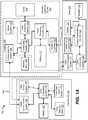
- Housing 105 can also include a battery 112, which can be any suitable energy storage device, such as a lithium ion battery, capable of storing energy and discharging stored energy to operate housing 105. The discharged energy can be used to power the electrical components of housing 105. In some embodiments, battery 112 can also be charged to replenish its stored energy. For instance, battery 112 can be coupled to power receiving circuitry 114, which can receive current from receiving element 116. Receiving element 116 can electrically couple with a transmitting element 118 of a case 103 in embodiments where receiving element 116 and transmitting element 118 are configured as exposed electrical contacts. Case 103 can include a battery 122 that can store and discharge energy to power transmitting circuitry 120, which can in turn provide power to transmitting element 118.
- a battery 112 can be any suitable energy storage device, such as a lithium ion battery, capable of storing energy and discharging stored energy to operate housing 105. The discharged energy can be used to power the electrical components of housing 105. In some embodiments,
- case 103 can be apprised of the status of wireless listening device 101 (e.g., charging status and the like).
- Case 103 can also include a speaker 123 coupled to case computing system 119 so that speaker 123 can emit audible noise capable of being heard by a user for notification purposes.
- Host device 130 to which housing 105 is an accessory, can be a portable electronic device, such as a smart phone, tablet, or laptop computer.
- Host device 130 can include a host computing system 132 coupled to a battery 135 and a host memory bank 134 containing lines of code executable by host computing system 132 for operating host device 130.
- Host device 130 can also include a host sensor system 136, e.g., accelerometer, gyroscope, light sensor, and the like, for allowing host device 130 to sense the environment, and a host user interface system 138, e.g., display, speaker, buttons, touch screen, and the like, for outputting information to and receiving input from a user.
- a host sensor system 136 e.g., accelerometer, gyroscope, light sensor, and the like
- a host user interface system 138 e.g., display, speaker, buttons, touch screen, and the like, for outputting information to and receiving input from a user.
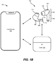
- FIG. 1B is a simplified illustration of an exemplary portable electronic listening device system 150 having a host device 152 configured as a smart phone, a case 154, and a pair of wireless listening devices 156 configured as a pair of in-ear hearing devices, according to some embodiments of the present disclosure.
- Host device 152 can be wirelessly communicatively coupled with case 154 so that host device 152 can receive the charge level data for case 154 and/or the charge level data for wireless listening devices 156.
- Host device 152 can also be wirelessly communicatively coupled with wireless listening devices 156 so that audio data can be transmitted to wireless listening devices 156 for play back to a user, and audio data can be received by host device 152 as recorded/inputted from microphones in wireless listening devices 156.
- Wireless listening devices 156 can be wirelessly communicatively coupled with case 154 so that audio data from case 154 can be transmitted to wireless listening devices 156.
- case 154 can be coupled to an audio source different than host device 152 via a physical connection, e.g., an auxiliary cable connection. The audio data from the audio source can be outputted to case 154, which can then wirelessly transmit the data to wireless listening devices 156. That way, a user can hear audio by way of wireless listening devices 156 even though the audio device does not have wireless audio output capabilities.
- each wireless listening device 156 can include a housing 158 formed of a body 160 and a stem 162 extending from body 160, where housing 158 is formed of a monolithic outer structure.
- Body 160 can include an internally facing microphone 164 and an externally facing microphone 166 for purposes discussed herein with respect to FIGS. 7-10 .
- Externally facing microphone 166 can be positioned within an opening defined by portions of body 160 and stem 162 as shown in FIG. 1B . By extending into both body 160 and stem 162, microphone 166 can be large enough to receive sounds from a broader area around the user.
- housing 158 can be attached to an eartip 174 that can direct sound from an internal audio driver out of housing 158 and into a user's ear canal.
- wireless listening devices 156 can be configured as in-ear hearing devices.
- Stem 162 can be substantially cylindrical in construction, but it can include a planar region 168 that does not follow the curvature of the cylindrical construction. Planar region 168 can indicate an area where the wireless listening device is capable of receiving user input. For instance, a user input can be inputted by squeezing stem 162 at planar region 168.
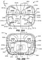
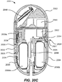
- Stem 162 can also include electrical contacts 170 and 172 for making contact with corresponding electrical contacts in case 154, as will be discussed further herein with respect to FIG. 20A .
- wireless listening devices 156 can include several features can enable them to be worn by a user all day. Its eartip can be soft and pliable, and can include control leaks to release trapped pressure in an ear canal so that it is comfortable to wear. Its functionality can also enable wireless listening devices 156 to provide an audio interface to host device 152 so that the user may not need to utilize a graphical interface of host device 152. In other words, wireless listening devices 156 can be so sophisticated that it can enable the user to perform day-to-day operations from host device 152 solely through interactions with wireless listening devices 156.
- wireless listening devices 156 can function in transparent mode where audible sounds from the surrounding environment can be recorded by externally facing microphone 166 and immediately replicated to the user by outputting the sound through eartip 174 to be heard by the user. Additionally, for those users that are hard of hearing, wireless listening devices 156 can increase the volume of the sounds in the surrounding environment for the user to hear.
- wireless listening devices 156 can decrease the volume of the sounds in the surrounding environment to a more acceptable level. This adjustment between increasing and decreasing volume can occur automatically to maintain a certain decibel range, in some embodiments. Thus, wireless listening devices 156 can enable a true hands free experience for the user.
- eartip 124 can attach to, and detach from, housing 105, as shown in FIGS. 2A and 2B.
- FIG. 2A is a side-view illustration of an exemplary wireless listening device 200 including an eartip 204 and a housing 202, where eartip 204 is attached to housing 202, according to some embodiments of the present disclosure
- FIG. 2B is a side view illustration of wireless listening device 200 where eartip 204 is detached from housing 202, according to some embodiments of the present disclosure.
- FIG. 2A is a side-view illustration of an exemplary wireless listening device 200 including an eartip 204 and a housing 202, where eartip 204 is attached to housing 202, according to some embodiments of the present disclosure
- FIG. 2B is a side view illustration of wireless listening device 200 where eartip 204 is detached from housing 202, according to some embodiments of the present disclosure.
- FIG. 2A is a side-view illustration of an exemplary wireless listening device 200 including an eartip 204 and
- eartip 204 can include a tip region 206 and a base region 208 that together form a monolithic structure, and a sound channel 210 that extends through both tip region 206 and base region 208.
- Tip region 206 can include a curved, annular surface 207 that inserts into an ear canal for directing sound from housing 202 to the user, and can be formed of a pliable material that can easily bend to conform to the inner surfaces of the ear canal for forming an acoustic seal.
- Eartip 124 can attach to housing 105 in various ways. For instance, eartip 124 can be magnetically attached to housing using magnets to magnetically attract eartip 124 to housing 105. Eartip 124 can also be attached to housing 105 using mechanical means, such as a screw and threaded hole attachment. In such instances, an opening of housing 105 can be threaded and base region 208 can be correspondingly threaded so that eartip 124 can be screwed into housing 105. Furthermore, eartip 124 can be simply adhered to housing 105 using an adhesive or any other chemical bonding. In certain embodiments, eartip 124 can have features that hook onto housing 105, or a separate wireform attachment mechanism can be implemented in housing 105 to latch onto eartip 124.
- Eartip 204 can be detached from housing 202, as shown in FIG. 2B , so that damaged eartips can be easily replaced or so that different types and/or sizes of eartips can be used to more comfortably fit in ear canals of different anatomical shapes and sizes.
- an eartip can be attached to, and detached from, the housing of a wireless listening device.
- the eartip can be positioned inside the ear canal of a user and direct sound outputted by the housing into the ear canal.
- an attachment mechanism can be implemented in the base of the eartip to enable the eartip to attach to, and detach from, the housing as discussed herein with respect to FIGS. 3A-3C .
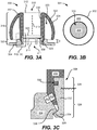
- FIG. 3A is a cross-sectional view 300 of an eartip 302 attached to an outer structure 304 of a housing via an attachment structure 308, according to some embodiments of the present disclosure. It is to be appreciated that discussion of FIG. 3A may refer to FIG. 3B for a better understanding of the structure of eartip 302.
- FIG. 3B is a top-down view 301 of eartip 302, according to some embodiments of the present disclosure.
- eartip 302 can include an eartip body formed of an inner eartip body 316 and an outer eartip body 322 that together form a monolithic structure.
- Outer eartip body 322 can extend around a perimeter/circumference of inner eartip body 316 and during manufacturing, can initially be formed together as a deformable tube that is later folded over so that outer eartip body 322 is positioned outside of inner eartip body 316 as shown.
- Inner eartip body 316 can be centered along a central axis 313 and define a sound channel 310 that extends through eartip 302 between an interfacing end 312 and an attachment end 314 of the eartip body.
- Sound channel 310 can be vacant space through which sound can travel from attachment end 314 to interfacing end 312.
- attachment end 314 can be an end of eartip 302 that is configured to attach to outer structure 304 of the housing so that sound generated by the housing can pass into sound channel 310 through an acoustic opening 311 of outer structure 304; and, interfacing end 312 can be an end of eartip 302 opposite from attachment end 314 where outer eartip body 322 begins to extend from inner eartip body 316 (such as at the top end of eartip 302) and that is configured to interface with (e.g., insert into) an ear canal of a user.
- sound channel 310 can be substantially aligned with acoustic opening 311 of outer structure 304 so that sound the from the housing can easily propagate into sound channel 310.
- Inner eartip body 316 in certain embodiments, can be substantially cylindrical and can define a cylindrical sound channel 310.
- sound channel 310 can be substantially circular. It is to be appreciated that a circular profile is merely exemplary and that the top-down profile of sound channel 310 can have other profiles, such as ovular, triangular, rectangular, oblong, and the like.
- eartip 302 can include a tip region 318 and a base region 320 (e.g., tip region 206 and base region 208 in FIG. 2 ).
- Tip region 318 can be a part of eartip 302 that inserts into the ear canal of the user while base region 320 can be a part of eartip 302 that extends toward and attaches to outer structure 304 of the housing.
- Base region 320 can be configured so that eartip 302 minimally protrudes from outer structure 304.
- base region 320 can be configured so that tip region 318 is positioned a distance D away from a non-protruding surface of outer structure 304 that is less than 3 mm, particularly less than 2 mm in some embodiments.
- eartip 302 may better resist inadvertent separation forces to minimize accidental detachment, as well as minimally protrude from the user's ear when worn for a pleasing appearance.
- outer eartip body 322 can be a part of tip region 318 that extends from, and is coupled to, inner eartip body 316 at interface end 312 of eartip 302 toward attachment end 314. Outer eartip body 322 can bend and conform to the contours of the ear canal to form an acoustic seal to prevent sound from leaking out of the ear canal.
- outer eartip body 322 can be formed of a thin, compliant material, e.g., silicone, thermoplastic urethane, thermoplastic elastomer, or the like, that can easily bend and deflect inward and outward to conform to various contours of the ear canal.
- Inner eartip body 316 can have a larger thickness than outer eartip body 322 because it does not contact the ear canal and provides some structural integrity to eartip 300; thus, it does not need to be as compliant as outer eartip body 322 for conforming to the ear canal.
- Outer eartip body 322 can include a curved interface surface 324 that is sized and shaped to make contact with the inner surfaces of the ear canal for forming an acoustic seal when the wireless listening device is worn by the user.
- Outer eartip body 322 can taper toward interfacing end 312 to make it easier for the user to insert eartip 302 into his or her ear canal.
- a part of outer eartip body 322 closest to attachment end 314 can bend back toward inner eartip body 316 to reduce the chances of outer eartip body 322 flipping inside-out.
- FIG. 3C is a close-up, cross-sectional view illustration of attachment structure 308 attached to outer structure 304 via attachment features 326, according to some embodiments of the present disclosure.
- Attachment structure 308 can include a frame portion 328 and attachment features 326 that together form a monolithic structure.
- Frame portion 328 can be a ring positioned around central axis 313, and can include a groove 330 extending around an outer circumference of frame portion 328. Groove 330 can increase the surface area that contacts inner eartip body 316 to enhance the structural coupling between inner eartip body 316 and attachment structure 308.
- attachment features 326 can extend from frame portion 328 in a direction that is parallel to the central axis 313 so that attachment features 326 can attach to outer structure 304 and position central axis 313 at an angle that is substantially perpendicular to the plane in which outer structure 304 is oriented at the attachment location (which is shown to be horizontal in FIG. 3A ).
- Each attachment feature 326 can include an arm 332 and a hook 334 for attaching to outer structure 304.
- Hook 334 can be a portion of attachment feature 326 that bends away from central axis 313 of attachment structure 308 so that hook 334 can grab onto a lip 336 of outer structure 304 that protrudes into acoustic opening 311 of outer structure 304.
- lip 336 extends into acoustic opening 311 and includes an attachment surface 335 to which hook 334 can attach.
- Arm 332 can be a cantilevered structure that applies outward force when hook 334 is engaged with lip 336 to secure eartip 302 to outer structure 304 of the housing.
- lip 336 can extend a short distance away from outer structure 304 and provide a slanted surface upon which base portion 320 of eartip 302 can rest as shown in FIG. 3C to further secure a robust attachment.
- the plurality of attachment features 326 can secure eartip 302 to outer structure 304 with a force that is strong enough to withstand inadvertent detachment (e.g., when the listening device is repositioned in an ear canal or is being held in a user's hand), but weak enough to allow intentional detachment by the user (e.g., when the user wants to change eartip types or when the user wants to clean eartip 302).
- the plurality of attachment features 326 can also provide tactile feedback when engaged, such as a snapping sensation, when hooks 334 engage with lip 336.
- attachment structure 308 allows eartip 302 to attach to outer structure 304 by inserting into an opening of outer structure 304, instead of wrapping around a rigid protrusion of outer structure 304 as is conventionally done. Accordingly, when attached, a portion of eartip 302 may be positioned within outer structure 304 of the housing. In such embodiments, attachment structure 308 requires less total space to securely attach eartip 302 with outer structure 304, and moves the failure point in the event of a drop/bend/pinch event to base region 320 of eartip 302 as opposed to outer structure 304 of the housing. This substantially reduces the cost of replacement/repair of the wireless listening device/in-ear hearing device.
- FIG. 3D is an exploded view illustration of an exemplary wireless listening device 350 including a wireform attachment mechanism 351 for attaching an eartip 352 to a housing 353, according to some embodiments of the present disclosure.
- eartip 352 can be attached to a nozzle 359, and nozzle 359 can be securely attached to, or be a portion of, housing 353.
- nozzle 359 can be a separate structure from housing 353 that is attached via welding or adhesive so that nozzle 359 cannot separate from housing 353.
- nozzle 359 can be a monolithic portion of housing 353 that protrudes outward away from housing 353.
- Nozzle 359 can include openings 361 through which portions of wireform attachment mechanism 351 can extend to latch eartip 352 to housing 353, and nozzle 359 can include a mesh 303 to cover the opening of nozzle 359 and prevent dust and debris from entering housing 353, as will be discussed further herein with respect to FIG. 3I .
- Wireform attachment mechanism 351 can be an independent and separate structure from nozzle 359 and housing 353 that makes contact with both components. Because eartip 352 attaches to housing 353 by way of wireform attachment mechanism 351, eartip 352 may be configured to complement the design of wireform attachment mechanism 351, as will be discussed further herein.
- FIG. 3E illustrates the eartip body that includes inner eartip body 325 separated from outer eartip body 327 by a deflection zone
- inner eartip body 325 and outer eartip body 327 can be one solid, compliant structure formed of silicone.
- a deflection zone may not be defined between inner eartip body 325 and outer eartip body 327.
- Eartip 352 can also include a mesh 303 for preventing debris and other unwanted particles from falling completely through sound channel 331.
- Mesh 303 can be a soft, porous fabric that allows sound to propagate through but prevents debris from passing through.
- mesh 303 can be formed of a polyester fabric.
- mesh 303 extends into upper region 378 of attachment structure 343 so that mesh 303 can be securely fixed within eartip 352 by the rigid structure of attachment structure 343.
- the structure of the eartip body i.e., inner eartip body 325 and outer eartip body 327) can be formed of a different, more pliable material than what is used for forming attachment structure 343.
- inner eartip body 325 and outer eartip body 327 can be formed of silicone, while attachment structure 343 is formed of a stiff polymer, such as polycarbonate.
- the soft pliable structure of inner eartip body 325 may be securely attached to attachment structure 343.
- inner eartip body 325 and outer eartip body 327 are molded over attachment structure 343 so that a degree of chemical bonding is achieved at the interface between the two structures during the manufacturing process.
- several through-holes 349 can be positioned around an upper region of attachment structure 343 to allow the soft material of which inner eartip body 325 is formed to pass from an outer surface 342 of attachment structure 343 to an inner surface 344 of attachment structure 343.
- the amount of material that passes through through-holes 349 can result in a formation of a thin, annular structure 346 that extends across a part of inner surface 344 of attachment feature 343 near through-holes 349.
- annular structure 346 can be an extension of inner eartip body 325 that covers at least part of inner surface 344 of attachment structure 343.
- annular structure 346, material within pass-throughs 349, inner eartip body 325, and outer eartip body 327 can all be part of a same monolithic structure.
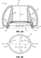
- attachment structure 343 also includes a control leak 348 set in a cavity region 307, as will be discussed further herein with respect to FIG. 6D .
- Control leak 348 can provide an atmospheric pass-through between an outside environment and sound channel 331 so that eartip 352 does not completely seal the ear canal and trap pressure within the ear canal. This can allow for a more comfortable user experience and can also improve the acoustic performance of the listening device.
- Cavity region 307 can be a shallow cavity defined by inner surface 344 of attachment structure 343 to mitigate the chances of control leak 348 from being occluded from the inside of inner eartip body 325, as will be discussed further herein with respect to FIG. 6E .
- outer eartip body 327 can be modified to mitigate the changes of control leak 348 from being occluded from the outside of inner eartip body 325, as will be discussed further here with respect to FIGS. 6F-6H .
- inner eartip body 325 can further include an annular attachment flange 360 extending around a perimeter of attachment structure 343 at attachment end 337.
- Attachment flange 360 can form an acoustic seal by pressing against an inner side surface of a housing, e.g., housing 353 in FIG. 3D .
- Attachment flange 360 can extend away from center line 329 of inner eartip body 325 and in an upward and lateral direction as shown in FIG. 3E .
- wireform attachment mechanism 351 can attach eartip 352 to nozzle 359, and thus to housing 353.
- Wireform attachment mechanism 351 can be configured to enable eartip 352 to mechanically attach to and detach from housing 353.
- wireform attachment mechanism 351 can enable eartip 352 to latch onto nozzle 359 with application of low insertion force and resist separation from housing 353 once eartip 352 is latched onto nozzle 359.
- wireform attachment mechanism 351 does not have to apply active force to maintain attachment. Rather, the physical structure of wireform attachment mechanism 351 can allow eartip 352 to remain attached to nozzle 359. That way, wireform attachment mechanism 351 does not have to apply a high amount of active force to keep eartip 352 attached to nozzle 359 and allow attachment by application of a low insertion force, as will be discussed further herein with respect to FIG. 3I .
- Wireform attachment mechanism 351 can include a body formed of a single, contiguous strip of wire that is bent in various directions to create a compressible spring that can apply pressure in a lateral direction to attach eartip 352 to nozzle 359.
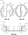
- FIGS. 3F-3H are illustrations of wire form attachment mechanism 351 that has an s-shaped profile configured to compress toward its center when engaging with an eartip, according to some embodiments of the present disclosure. Specifically, FIG. 3F is a top-down view illustration of wireform attachment mechanism 351 in its uncompressed state, FIG. 3G is a top-down view illustration of uncompressed wireform attachment mechanism 351 superimposed over its compressed state, and FIG. 3H is a side-view illustration of wireform attachment mechanism 351 superimposed over its release state, according to some embodiments of the present disclosure.
- the strip of wire forming wireform attachment mechanism 351 can have an s-shape profile that includes a center segment 354 having opposing ends from which two wireform features extend.
- the two wireform features can include a first wireform feature 355a and a second wireform feature 355b that each includes respective intermediate segments 356a-b, u-shaped segments 357a-b, and end segments 358a-b.
- U-shaped segments 357a-b can be positioned between intermediate segments 356a-b and end segments 358a-b as shown in FIG. 3F .
- U-shaped segments 357a-b may not appear to have a u-shaped profile from the top-down view in FIG.
- center segment 354 can have a substantially straight profile/construction
- intermediate segments 356a-b extending from center segment 354 can have an arcuate profile/construction.
- the curvature of intermediate segments 356a-b can conform to a segment of a corresponding outer profile of nozzle 359 so that intermediate segments 356a-b can achieve a better fit with nozzle 359.
- Wireform attachment mechanism 351 can also include end caps 366a-b that cover respective lateral bend portions 375a-b of u-shaped segments 357a-b. As shown in the side-view illustration in FIG. 3H , end caps 366a-b can have a beveled top corner 377a-b and a flat bottom surface 379b. Beveled top corner 377a-b can transition vertical insertion force into lateral force to bend wireform attachment mechanism 380 during attachment, and flat bottom surface 379b can resist separation of the eartip once attached and lock onto respective portions of an attachment structure (e.g., portions of the lower region of the attachment structure below recesses 345a-b discussed herein with respect to FIG. 3E ).
- an attachment structure e.g., portions of the lower region of the attachment structure below recesses 345a-b discussed herein with respect to FIG. 3E ).
- wireform attachment mechanism 351 can bend into a compressed state 315, as shown in FIG. 3G represented by a dotted silhouette of parts of wireform attachment mechanism 351, to allow the attachment structure of the eartip to slide over the nozzle.
- opposite halves of wireform attachment mechanism 351 can be cantilever beams that bend from a midpoint 317 of center segment 354.
- end caps 366a-b can move inwards to allow the eartip to be released from the housing and separated.
- the direction of curves 321a-b along which u-shaped segments 357a-b rotate can be opposite from one another. For instance, curve 321a can be clockwise while curve 321b can be counter-clockwise, as shown in FIG. 3H .
- Mesh 303 can be formed as a multi-layered structure including a cosmetic mesh 305a and an acoustic mesh 305b adhered to the cosmetic mesh, where cosmetic mesh 305a forms an outer surface of nozzle 359 and is formed of an interlaced network of stiff wire, while acoustic mesh 305b is adhered to an inner surface of cosmetic mesh 305a and is formed of a porous fabric.
- cosmetic mesh 305a can be formed of interlaced stainless steel and acoustic mesh 305b can be formed of polyester.
- a welding ring 363 can be used to securely attach housing 353 to nozzle 359.
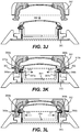
- FIGS. 3J-3L are a series of illustrations showing different points along the process of attaching eartip 352 to nozzle 359, according to some embodiments of the present disclosure.
- eartip 352 can be pressed into housing 353 in a downward direction 369 as shown in FIG. 3J . Pressing eartip 352 downward causes frame portion 362 of eartip 352 to press against end caps 366a-b of wireform attachment mechanism 351, as shown in FIG. 3K .
- the slope of beveled corners 373a-b allow end caps 366a-b to easily press inward toward center segment 354 when force in downward direction 369 is applied to attach eartip 352 to nozzle 359.
- the bottom corner of end cap 366a-b may not include beveled corners so that end caps 366a-b can resist substantially greater separation forces in upward direction 372.
- eartip 352 can be attached under the application of low insertion force in downward direction 367 and separated under the application of high force in upward direction 372.
- This force profile enabled by wireform attachment mechanism 351 can provide improved user experience and attachment reliability.
- the attachment force sufficient to attach eartip 352 to nozzle 359 can be applied by a set of magnets (not shown).
- u-shaped segments 357a-b can include respective lateral bend portions 367a-b to which end caps 366a-b are attached, as shown in FIG. 3I .
- Lateral bend portions 367a-b can extend in a horizontal plane parallel to the plane in which center segment 351 and intermediate segments 356a-b are positioned in a non-overlapping manner.
- lateral bend portions 367a-b can be positioned at an angle with respect to the rest of the u-shaped segment 357a-b, such as at a 90 degree angle. Lateral bend portions can improve the structural strength of end caps 366a-b and provide a stiff frame to which it can attach.
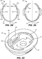
- FIGS. 3M-3O illustrate an exemplary wireform attachment mechanism 380 that has a u-shaped profile configured to compress toward its center when engaging with an eartip, according to some embodiments of the present disclosure.
- FIG. 3M is a top-down view illustration of wireform attachment mechanism 380 in its uncompressed state
- FIG. 3N is a top-down view illustration of uncompressed wireform attachment mechanism 380 superimposed over its compressed state
- FIG. 3O is a bottom-up perspective view illustration of wireform attachment mechanism 380 positioned in a nozzle, according to some embodiments of the present disclosure.
- wireform attachment mechanism 380 can include two wireform features that are delineated by a center line 386 and configured as mirror images of one another where each wireform feature includes an intermediate segment formed by a respective half of connecting segment 383.
- Connecting segment 383 can be coupled to ends of lateral bend portions 381a-b opposite from the ends to which lateral bend portion 381a-b are attached.
- end caps 384a-b can be attached over lateral bend portions 381a-b, similar to end caps 366a-b and lateral bend portions 375a-b discussed herein with respect to FIG. 3I , for inserting into respective openings in the nozzle for attaching an eartip to the nozzle.
- nozzle 359 can have an inner surface 388 that matches the curvature of wireform attachment mechanism 380.
- Inner surface 388 can include a recess 389 that provides space for end segments 382a-b to be positioned, as well as to provide clearance space for allowing end segments 382a-b to move when wireform attachment mechanism 380 transitions from an uncompressed state to a compressed state, as discussed herein with respect to FIG. 3N .
- joint region 387 of wireform attachment mechanism 380 can be freely resting on inner surface 388, or joint region 387 can be securely attached to inner surface 388 via an adhesive, welding, or any other suitable attachment method.
- wireform attachment mechanism 390 shown in FIG. 3P can be constructed of a single, contiguous strip of wire that is bent to have a u-shaped profile substantially similar to that shown in FIG. 3M .
- wireform attachment mechanism 390 can include a pair of lateral bend portions 391a-b coupled to respective u-shaped segments 392a-b that are coupled together via a connecting segment 393 formed of a single curve of wire.
- wireform attachment mechanism 390 can include two wireform features that are delineated by a center line 396 and configured as mirror images of one another.
- Each wireform feature can include an end segment, a u-shaped segment including a lateral bend portion, and an intermediate segment formed by a respective half of connecting segment 393.
- Connecting segment 393 can be coupled to ends of lateral bend portions 391a-b opposite from the ends to which lateral bend portion 391a-b are attached.
- End caps 394a-b can be attached over lateral bend portions 391a-b for inserting into respective openings in the nozzle for attaching an eartip to the nozzle.
- wireform attachment mechanism 390 When the eartip presses against end caps 394a-b during attachment, wireform attachment mechanism 390 can bend into a compressed state 395, as shown in FIG. 3P and represented by a dotted silhouette of parts of wireform attachment mechanism 390, to allow the frame portion of the eartip to slide over the nozzle. Unlike wireform attachment mechanism 380 where the entire halves compresses laterally during attachment, wireform attachment mechanism 390 can instead rotate only the u-shaped segments 392a-b around an axis. The axis can be defined by a line that intersects the two points where the end segments and intermediate segment meet u-shaped segments 392a-b, as shown by axes 396a-b in FIG. 3M .
- end caps 394a-b can move inwards to allow the eartip to move toward the nozzle until end caps 394a-b snap into recesses of the eartip, as discussed herein with respect to FIG. 3L .
- the direction of curves 397a-b along which u-shaped segments 392a-b rotate can be opposite from one another. For instance, curve 397a can be clockwise while curve 397b can be counter-clockwise, as shown in FIG. 3P .
- an eartip can be configured as a sensor for detecting when the wireless listening device is worn by a user.
- the eartip can be configured as a capacitive sensor that changes in capacitance when the eartip is inserted in an ear canal.
- FIG. 4A is an exemplary eartip 400 configured as a capacitive sensor, according to some embodiments of the present disclosure.
- eartip 400 can include a first conductive structure 402 and a second conductive structure 404 positioned within tip region 318 of eartip 400 and separated by deflection zone 323.
- First conductive structure 402 can be a metal plate bent into a inner eartip body-like shape that can be positioned on an outer surface of inner eartip body 316 in some embodiments, or a conductive inner eartip body 316 by doping inner eartip body 316 with conductive material to convert inner eartip body 316 into a conductive structure.
- second conductive structure 404 can be a metal plate bent and curved to conform to an inner surface of outer eartip body 322, or be a conductive outer eartip body 322 by doping outer eartip body 322 with conductive material to convert outer eartip body 322 into a conductive structure.
- each conductive structure 402 and 404 and deflection zone 323 can define a first capacitance when eartip 300 is not inserted into an ear canal, but change in capacitance (e.g., increase in capacitance) when eartip 300 is inserted into an ear canal due to the deflection of outer eartip body 322 toward inner eartip body 316 when eartip 300 is inserted into the ear canal, as shown in FIGS. 4B and 4C .
- each conductive structure 402 and 404 extends around the entire circumference of eartip 400. However, in some other embodiments, each conductive structure 402 and 404 may extend around only a portion of the entire circumference of eartip 400. In such instances, each conductive structure 402 and 404 can be configured as a strip of conductive plating that are positioned directly across from one another to form a capacitor.
- FIGS. 4B and 4C are cross-sectional views of eartip 400 when it is inserted into an ear canal, according to some embodiments of the present disclosure.
- eartip 400 can bend and conform to the inner surfaces of ear canal 406 when eartip 400 is inserted into ear canal 406.
- Housing 202 may not bend or conform when the wireless listening device, e.g., in-ear hearing device, is worn by the user.
- outer eartip body 322 may bend into deflection zone 323 when the wireless listening device is worn, thereby causing some parts of first and second conductive structures 402 and 404 to be positioned closer to one another.
- eartip 400 can be configured to have a first capacitance when it is not inserted into an ear canal, and a second capacitance when it is inserted into an ear canal.
- some embodiments can configuring the eartip as an optical indicator that changes when the eartip is inserted into an ear canal.
- the eartip can include a pattern of lines and spaces on an inner surface of the outer eartip body that can be observed by an optical sensor in the housing to determine if the wireless listening device is worn by a user, as discussed further herein with respect to FIGS. 5A-5C .
- FIG. 5A is a bottom-up view of an exemplary eartip 500 configured with patterned lines 502 separated by spaces 504 on an inner surface of its outer eartip body 506, FIG.
- FIG. 5B is a side-view of an exemplary wireless listening device 501 with eartip 500 and a housing 510 with an optical sensor 508 for observing the inner surface of outer eartip body 506, and FIG. 5C is a bottom-up view of eartip 500 after deflection from being inserted into an ear canal, according to some embodiments of the present disclosure.
- the inner surface of outer eartip body 506 can have a series of patterned lines 502 separated by gaps 504.
- Lines 502 can extend along the entire circumference of outer eartip body 506 and thus can have a substantially circular shape.
- the thickness of each line can be the same as or different from other patterned lines, and the size of each gap can similarly be the same as or different from the size of other gaps.
- the series of patterned lines 502 can be observed by an optical sensor 508 that faces eartip 500.
- optical sensor 508 can detect changes in patterned lines 502 when eartip 500 is inserted into an ear canal. For instance, as shown in FIG.
- patterned lines 502 and gaps 504 can alter in shape due to outer eartip body 506 deflecting and conforming to an inner surface of an ear canal.
- optical sensor 508 can observe pattern lines 502 and gaps 504 as a whole, or observe a portion 510 of patterned lines 502 and gaps 504.
- Optical sensor 508 can, in some embodiments, observe only a portion of the series of patterned lines 502 and gaps 504 in front of optical sensor 508.
- more than one optical sensor can be implemented to observe the entire patterned lines 502 and gaps 504 around the circumference of eartip 500. When more than one optical sensor is used, they can be positioned axially symmetrical around the opening in housing to which eartip 500 is attached.
- Wireless listening device 501 can determine that it is worn by a user when patterned lines 502 and gaps 504 deflect a threshold distance away from its initial position when it is not inserted into an ear canal, e.g., as shown in FIG. 5A .
- eartip 500 can be configured to have a first line pattern when it is not inserted into an ear canal, and a second line pattern different from the first line pattern when it is inserted into an ear canal.
- Each line pattern can be substantially circular and extend around a circumference of eartip 500.
- the wireless listening device can, enhance user experience by automatically initiating specific, targeted UI controls related to the wireless listening device when it detects that it is worn, such as automatically providing play/pause options for music, answering/ending phone calls, and the like. Additionally, the wireless listening device can be configured to detect unique deflection patterns and associate those unique deflection patterns with individual users. By doing this, the wireless listening device can automatically set its operational settings to reflect specific predefined preferences of that user. Furthermore, being able to detect unique patterns can allow the wireless listening device to be able to identify which eartip type is attached to the housing. For instance, different sizes of eartips can have different, unique patterns of lines and gaps.
- the housing can be configured to observe the unique patterns of lines and gaps when the eartips are not inserted into an ear canal and automatically determine which eartip is attached to the housing by matching the observed patterns of lines and gaps with a list of known patterns of lines and gaps for the different types of eartips.
- optical sensor 508 instead of observing the individual line and gap patterns, can measure the observed color of the inner surface of eartip 500 as a whole. That way, a less expensive optical sensor can still be used to detect the identity of eartip 500.
- Control leaks of different shapes and sizes can have more or less resistance to occlusion. For instance, elongated control leaks that are in the shape of ovals, rectangles, or oblong openings can be more resistant to occlusion from debris than control leaks that are in the shape of circles or squares because elongated control leaks have greater opening areas than non-elongated control leaks.
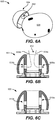
- eartip 604 includes a single control leak 602, while other embodiments can have more than one control leak, as shown in FIG. 6B and 6C .
- both control leaks 608a and 608b can be configured to have the same size and shape. However, in some embodiments, control leaks 608a and 608b can be configured to have different sizes and shapes, as shown in FIG. 6C . That is, eartip 603 in FIG.
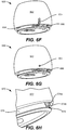
- eartip 660 can have an outer eartip body 662 that is modified to include a hole 664 positioned near the attachment end of eartip 660 and positioned over control leak 666.
- hole 664 is shown as a circular hole, any other shape can be used to form hole 664, such as an ovular, oblong, rectangular, square, triangular, and the like.
- the housing can be implemented to enhance the user experience of the wireless listening device.
- one or more sound ports, control leaks, and microphones can be implemented in the housing to improve output sound quality, comfort, and user interface methods of the wireless listening device, as will be discussed further herein.
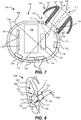
- Battery 706 can be any suitable energy storage device that can store and discharge stored energy, such as a lithium ion battery, and the like. Battery 706 can be electrically coupled to electronic devices 710 and driver 715 through interconnection structure 708 so that when discharging, the discharged energy can be used to power electronic devices 710 and driver 715. Interconnection structure 708 can be any suitable component that can route signals and power between electronic devices, such as a printed circuit board (PCB) or a flexible PCB. Electronic devices 710 can be any suitable semiconductor devices for operating wireless listening device 700, such as microcontrollers, processors, field programmable gate arrays (FPGA), application specific integrated circuits (ASIC), dynamic random-access memory (DRAM) and the like.
- FPGA field programmable gate arrays
- ASIC application specific integrated circuits
- DRAM dynamic random-access memory
- Electronic devices 710 can be configured to interact with one another and various other internal components to perform various functions that improve the user experience as well as the sound quality of wireless listening device 700, as will be discussed in detail further herein.
- Driver 715 can be an electrical device that generates sound waves, such as a speaker and/or a subwoofer.
- Driver 715 can be coupled to, and operated by, the one or more electronic devices 710.
- wireless listening device 700 When wireless listening device 700 is worn by a user, wireless listening device 700 can provide sound to an ear canal through eartip 703, which is better shown in FIG. 8 .
- tuned control leak 713 can be an opening within outer structure 704 for allowing air to flow out of housing 702.
- the result achieved by releasing the air out of housing 702 may be different from the result achieved by tuned bass port 711.
- tuned control leak 713 can be configured to relieve pressure trapped the ear canal when a seal is formed between outer eartip body 705 and ear canal 804, such as when wireless listening device 700 is worn by a user.
- pressure from the ear canal can flow through a pressure release pathway 726 that flows from opening 717 into outer structure 704 and then out into the atmosphere through tuned control leak 713.
- wireless listening device 700 can operate in transparency mode where sounds received from outside of the ear canal can be reproduced with or without augmentation by wireless listening device 700 so that the user can hear sounds from the outside environment. This enables the user to still hear sounds from his environment, such as spoken words from a person with which the user is conversing, even though the user's ear canal may be sealed by outer eartip body 705 of eartip 703.
- internally facing microphone 716 can also enable wireless listening device 700 to perform acoustic self-testing to determine the presence of occluded ports, control leaks, and/or external microphones, and to inform the user of improper fit or how to change the positioning/use of wireless listening device 700 when occlusion is detected to ensure the best possible acoustic performance.
- wireless listening device 1001 when wireless listening device 1001 is worn by a user, wireless listening device 1001 can measure the operation of externally facing microphone 1012 and compare the measured operation of externally facing microphone 1012 with the expected operation of externally facing microphone 1012. If the measured operation is different from the expected operation by greater than a threshold amount, wireless listening device 1001 and/or the host device can determine that externally facing microphone 1012 is occluded and send the necessary alerts/instructions to the user to correct the positon of wireless listening device 1001.
- externally facing microphones 712 and 714 and internally facing microphone 716 are positioned on opposing halves of housing 702 when divided in half by dividing line 806.
- Dividing line 806 can be a line that divides housing 702 in two halves, where one half is positioned closer to ear canal 804 than the other half.
- dividing line 806 can be perpendicular to axis 709 of acoustic opening 719 and inner eartip body 707. And, dividing line 806 can be positioned so that housing 702 is divided into two halves.
- tuned bass port 711 and tuned control leak 713 When placed close to externally facing microphones 712 and 714, tuned bass port 711 and tuned control leak 713 can cause echo and feedback distortion. Thus, in some embodiments, tuned bass port 711 and tuned control leak 713 can be positioned away from externally facing microphones 712 and 714. For instance, where dividing line 806 divides housing 702 in half and externally facing microphones 712 and 714 are positioned on one half of housing 702, tuned bass port 711 and tuned control leak 713 can be positioned on the other half of housing 702 next to eartip 703.
- acoustic shielding component 1102 can be formed of a porous plastic material constructed of a solid matrix defining a plurality of pores that allows the microphone to be exposed to the atmosphere but resists liquid and debris from entering housing 1106.
- acoustic shielding component 1102 can be a three-dimensional porous structure that extends at least partially between externally facing microphone 1104 and an outer surface 1108 of housing 1106.
- acoustic shielding component 1102 can completely fill in opening 1110 so that acoustic shielding component 1102 extends from an inner surface 1112 of housing 1106 to outer surface 1108 of housing 1106.
- External surface 1114 of acoustic shielding component 1102 can face outside of housing 1106 and be substantially planar with the immediately adjacent regions of external surface 1108 of housing 1106.
- external surface 1114 of acoustic shielding component 1102 is curved to seamlessly integrate with the curvature/profile of outer surface 1108 of housing 1106.
- the substantial planarity and seamless integration between external surface 1114 and outer surface 1108 can avoid any structural step formations and recesses at their interface, thereby substantially mitigating the formation of acoustic turbulence as air 1116 moves quickly past opening 1110 while still enabling external noise to filter through to microphone 1104. Mitigating acoustic turbulence increases microphone performance in outdoor environments.
- Support post 1138 can be an extension of housing 1126 that extends toward, and in some instances makes contact with, acoustic shielding component 1122.
- Support post 1138 can be positioned so that it makes contact with a central region of acoustic shielding component 1122.
- a stiffener can be implemented to provide structural rigidity to acoustic shielding component 1122, and a grounding tab 1142 can couple acoustic shielding component 1122 to ground, as will be discussed further herein with respect to FIG. 12 .
- an outer periphery of an inner surface of mesh cover 1208 can extend upward to form a mesh wall 1210, which can make contact with the housing to improve stability when installed in the housing.
- Mesh wall 1210 can be substantially perpendicular to mesh cover 1208.
- mesh wall 1210 can define a tab 1212 that extends from a portion of mesh wall 1210.
- Tab 1212 can extend away from mesh cover 1208 so that when installed, tab 1212 can couple to an internal grounding feature, such as a grounding plane for an antenna. This may be better shown with brief reference to FIG. 11B , where tab 1142 of acoustic shielding component 1122 extends away from external surface 1130 and past microphone 1124 to couple to an internal grounding component.
- grounding cosmetic mesh 1204 damage to the device from electric static discharge can be avoided.
- mesh cover 1208, mesh wall 1210, and tab 1212 can together be a monolithic structure that forms cosmetic mesh 1204.
- Stiffener 1206 can be a solid, instead of porous, structure that has high rigidity for providing structural integrity to acoustic shielding component 1200 to resist deformation during drop events.
- Stiffener 1206 can include a plurality of ribs 1214 positioned between stiffener walls 1216a and 1216b. Ribs 1214 can follow a contour of cosmetic mesh 1204; thus, ribs 1214 can also include contours that conform to the topography of the external surface of the housing. Ribs 1214 can be evenly spaced apart from one another and be distributed across a length of acoustic shielding component 1200 to provide structural rigidity across the length of acoustic shielding component 1200.
- a distance between ribs 1214 near the center of stiffener 1206 can be greater than the distances between other pairs of ribs so that a gap 1220 can be formed to allow space for a support post, e.g., support post 1138 in FIG. 11B , to be positioned to provide additional support to acoustic shielding component 1200.
- gap 1220 is shown to be formed by stiffener 1206, other stiffeners may not have a gap and can instead have ribs in position of gap 1220 in the equally-spaced apart configuration.
- Stiffener 1206 can be formed of any suitable stiff material, such as stainless steel, and can be attached to cosmetic mesh 1204 via a plurality of laser welding points 1218 on stiffener walls 1216a-b. Stiffener walls 1216a-b can be portions of stiffener 1206 that bend upward for increasing surface area contact with cosmetic mesh 1204 housing to improve mechanical coupling with cosmetic mesh 1204. When attached, stiffener 1206 can be surrounded by mesh wall 1210.
- the battery and driver for a wireless listening device can be specifically positioned to decrease the size of its housing.
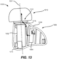
- FIG. 13 is a side-view illustration of a wireless listening device 1300 whose battery 1302 and driver 1304 are uniquely positioned to decrease the size of housing 1306, according to some embodiments of the present disclosure.
- eartip 1310 can be inserted into the ear canal. This allows housing 1306 to extend farther into the opening of the ear, and thus opens up more space for housing 1306 to occupy in the ear concha.
- larger components can be positioned next to eartip 1310.
- battery 1302 can be positioned adjacent to eartip 1310 such that its longest dimension, e.g., its width, is oriented along axis 1311 of eartip 1310.
- driver 1304 can be positioned immediately beside battery 1302 and oriented so that its longest dimension, e.g., its width can take full advantage of the extra space provided by the ear concha, as shown in FIG. 13 .
- an acoustic path 1316 of driver 1304 can be initially directed toward a flat, side surface of battery 1302, but then be redirected by the side surface toward opening 1312 of housing 1306 and ultimately out of opening 1312 and into the ear canal through eartip 1310.
- battery 1302 can be positioned so that an acoustic pathway can still be provided into opening 1312 beside battery 1302.
- the size of battery 1302, and thus the product battery life of wireless listening device 1300 can be maximized. Furthermore, by arranging battery 1302 and driver 1304 in this configuration, an antenna 1314 of wireless listening device 1300 can be positioned as far away from the user's body as possible, which can optimize antenna performance. Furthermore, smaller components can be more compactly arranged in the other regions of housing 1306, thereby allowing those regions of housing 1306 to be smaller, which thus reduces the overall size of housing 1306. Having a smaller size can improve the comfort and appearance of wireless listening device 1300 when it is worn.
- one or more processors of a wireless listening device can be configured to display the user's listening status and to interact with one or more sensors of the wireless listening device and execute commands stored in its memory to provide a variety of unique user interface methods for allowing the user to operate the wireless listening device, as will be discussed further herein.
- FIG. 14 is a side-view illustration 1400 of a wireless listening device 1402 configured to display the user's listening status, according to some embodiments of the present disclosure.
- wireless listening device 1402 can perform active noise cancellation functions, which can cancel out external sounds, and can perform transparency functions, which can amplify the external noise to the user.
- a dynamic visual indicator 1404 can be implemented by wireless listening device 1402 to display the user's listening status.
- visual indicator 1404 can be a light emitting diode that can display different colors of light and be positioned in housing 1406 where it can be seen when wireless listening device 1402 is worn by the user.
- visual indicator 1404 can display different colors of light depending on the particular operating mode of wireless listening device 1402.
- wireless listening device 1402 can be configured to output red light with visual indicator 1404 when wireless listening device 1402 is in the active noise cancelling mode, green light when wireless listening device 1402 is in the transparency mode, and/or orange light when wireless listening device 1402 is outputting sound, e.g., when the user is on a phone call or is listening to music. That way, people who may want to speak with the user can be apprised of the listening status of the user without needing the user to tell them him or herself.
- wireless listening device 1402 can be configured to output varied flashing patterns with visual indicator 1404 to show which mode is active. For instance, visual indicator 1404 can blink at a high frequency when wireless listening device 1402 is in the active noise cancelling mode, can output a steady light when wireless listening device 1402 is in the transparency mode, and can blink at a low frequency when wireless listening device 1402 is outputting sound when the user is on a phone call or listening to music. Alternatively, wireless listening device 1402 can be configured to output varied intensity of light with visual indicator 1404 to show which mode is active.
- visual indicator 1404 can emit bright light when wireless listening device 1402 is in the active noise cancelling mode, no light when wireless listening device 1402 is in the transparency mode, and dim light when the user is on a phone call or listening to music.
- FIG. 14 shows an embodiments where wireless listening device 1402 only has one visual indicator, embodiments are not so limited. Other embodiments can have more than one visual indicator where different combinations of visual indicators can output light based on which mode is active, without departing from the sprit and scope of the present disclosure.
- wireless listening device 1502 can associate an upward pull 1504 of the top of helix 1512 as a specific user input.
- antihelix 1514 of ear 1501 can also move upward by a lesser degree. This upward motion of antihelix 1514 can be detected by one or more optical sensors or microphones of wireless listening device 1502 to identify that top of helix 1512 has been pulled upward and thus in turn receive the specific user input associated with upward pull 1516.
- a spoken phrase including one or more words can be received as a user input, e.g., a voice command.
- electronic devices that enable voice control require the use of a trigger phrase in order for it to receive a user input.
- a trigger phrase can be a default phrase that is spoken by the user and recognized by the host device. Once the trigger phase is recognized, the host device can treat the next spoken phrase as a user input.
- Using a trigger phrase to recognize user inputs is a two-step process that can be cumbersome to use because the user has to speak two phrases instead of one. Furthermore, electronic devices may not be able to recognize when a specific user is speaking the command.
- an electronic device may mistakenly interpret a phrase spoken by a nearby non-user (e.g., someone who is not authorized to control the device) during the normal course of a conversation as a trigger phrase or a voice command.
- a nearby non-user e.g., someone who is not authorized to control the device
- the electronic device may inaccurately interpret parts of a conversation as unintentional voice commands.
- unauthorized users may inappropriately operate the electronic device by simply speaking the trigger phrase followed by a voice command.
- Even further authentication can be performed by the host device by utilizing one or more microphones of the wireless listening device.
- the host device can determine a directionality of the sound by analyzing the temporal movement of sound across two microphones. If the direction of the sound is moving away from the wireless listening device, then the authentication of the spoken phrase can be confirmed, or independently determined.
- a phrase spoken by the user during a conversation may match with a spoken phrase in the list of predetermined spoken phrases.
- the host device can be configured to measure temporal spacing before and after the spoken phrase, and compare the measured temporal space with a delay threshold. If the measured temporal spacing is greater than the delay threshold, then the host device can determine that the spoken phrase is a user input; otherwise, if the measured temporal spacing is less than the delay threshold, then the host device can determine that the spoken phrase is not a user input.
- the list of predetermined spoken phrases and the sound of the user's voice can be set during a one-time initialization protocol.
- the host device can follow a script to walk the user through various functions that can be initiated by voice command, such as turning on active noise cancellation mode, turning on transparency mode, adjusting the volume, playing/pausing music, and various other functions.
- the host device can also be configured to allow the user to define what the spoken phrases should be, thereby enhancing personal connection to the host device.
- embodiments discussed herein have shown housings that are substantially ovular/oblong (see FIGS. 2A-2B , 5B , 6A , 7 , 11A-11B ), and/or amorphous (see FIG. 13 ), embodiments are not limited to such configurations. Rather, some embodiments can include a stem that can be an extension of the outer structure, e.g., outer structure 704 in FIG. 7 , that protrudes from the body of the housing. As an extension of the outer structure, the stem can also enclose one or more electrical components within it. In some embodiments, the stem can be a tubular structure that has electrical contacts at its far end for interacting with a power source to charge the wireless listening device.
- FIG. 16A is a perspective view illustration of an exemplary wireless listening device 1600 that includes an eartip 1602 coupled to a housing 1604 that includes a body 1605 and a stem 1606, according to some embodiments of the present disclosure.
- Housing 1604 can be formed of a monolithic outer structure that forms both body 1605 and stem 1606.
- the outer structure can include a body portion 1608 and a stem portion 1610 that extends from body portion 1608.
- the elongated structure of stem 1606 can be used as an alignment feature for aligning wireless listening device 1606 to a charging device, such as an case, as will be discussed further herein with respect to FIG. 20 .
- Stem 1606 can also house electrical components and allow them to be positioned away from housing 1604 for coupling with the charging device. The different components within stem 1606 are further discussed in detail herein with respect to FIG. 16B .
- Insert mold 1616 can be a cosmetic piece that has similar aesthetics to outer structure 1607 of stem 1606 to provide an aesthetically pleasing seamless transition between insert mold 1616 and outer structure 1607.
- insert mold 1616 and contact 1614 can define an opening 1618 that extends through insert mold 1616 and contact 1614 from an outer surface of contact 1614 to an inner surface of insert mold 1616. Opening 1618 can be an acoustic port that can enable sound waves outside of stem 1606 to enter into stem 1606 so that an internal component, such as a microphone (not shown), can receive the sound waves.
- a gasket can be implemented between insert mold 1616 and outer structure 1607 of stem 1607. That way, a quality seal can be formed between them to prevent intrusion of moisture and/or debris.
- a wireless listening device can be one of a pair of wireless listening devices that are designed to fit in the ears of a user and to fit within an case when not in use.
- the case can protect the wireless listening devices from physical damage as well as provide a source of power for charging the wireless listening devices.
- case 2000 can include a hinge 2048 for opening and closing lid 2002.
- Hinge 2048 can be a bistable hinge that has two stable states: an open state and a closed state. Having a bistable hinge can allow for case 2000 to close without needing many magnets to generate a high magnetic attraction force to draw lid 2002 toward body 2004 to close lid 2002. Accordingly, only a single magnet 2050 may be sufficient to keep lid 2002 closed. Thus, in the stable closed state, hinge 2048 can cause lid 2002 to press on body 2004 and magnet 2050 may need to have just enough force to help it stay closed to resist inadvertent opening of lid 2002. Details of bistable hinge 2048 is discussed further herein with respect to FIGS. 27 and 28A-28C .
- Insert 2203 can be a structure that is pressed over internal frame 2100 and functions as part of the outer top structure of body 2200 of the case.
- sealing structure 2104 and first diverged portion 2023 can make contact with both insert 2203 and body 2200, while second diverged portion 2024 can make contact with only insert 2203 and not body 2200.
- second diverged portion 2024 can be configured to make a face seal with internal frame 2100, while the rest of sealing structure 2104 including first diverged portion 2023 can be configured to make both a face seal with insert 2203 and a radial seal with body 2200.
- magnets 2402b-c are shown as having polarities oriented in only one dimension (the z-dimension) and magnets 2402a and 2402d are shown as having polarities oriented in two dimensions (the z- and x-dimensions) for pulling shunt 2306 vertically downward, embodiments are not so limited. Other embodiments can include magnets 2402b-c that have polarities in two dimensions (the z-dimension and the y-dimension) and magnets 2402a and 2402d that have polarities in three dimensions.
- light emitter 2504 can be a light emitting device (LED) that has a square-like profile.
- LED light emitting device
- light tube 2501 can be have an input end 2506 that has a square-like profile, and an output end 2508 that has a circular profile.
- a middle region 2510 between input end 2506 and output end 2508 can be formed of a structure that gradually transitions from a square-like profile at input end 2506 to a circular profile at output end 2508.
- input end 2506 and output end 2508 can have any other profile and does not necessarily have to be square-like and circular, respectively. Rather, the profile of input end 2506 can depend on the shape of light emitter 2504, and the profile of output end 2508 can depend on design. Thus, input end 2506 and output end 2508 can be any other suitable shape, such as rectangular, triangular, oblong, and the like.
- light tube 2501 can include a flange 2514 for securing light tube 2501 to a body of the case, as shown in FIG. 20C . Flange 2514 can extend outward from a center axis 2503 of inner eartip body 2501 and along the same plane as input end 2506 of light tube 2501.
- FIGS. 26A-26B are simplified cross-sectional views of an exemplary magnetic attachment and sensor system 2600 that includes a hybrid retention and sensor shunt 2602, according to some embodiments of the present disclosure. Specifically, FIG. 26A is a simplified cross-sectional view of magnetic attachment and sensor system 2600 when a lid 2610 is opened, and FIG.
- lid 2610 when lid 2610 is closed, as shown in FIG. 26B , lid 2610 can contact body 2606.
- magnetic fields 2612 can propagate through hybrid retention and sensor shunt 2602 so that a magnetic attractive force can be generated to assist the bistable hinge in pulling lid 2610 shut.
- magnetic fields 2612 can propagate through hybrid retention and sensor shunt 2602 by entering a top surface of hybrid retention and sensor shunt 2602 and exiting a bottom surface of hybrid retention and sensor shunt 2602.
- hybrid retention and sensor shunt 2602 is formed of a ferrous material, such as steel, magnetic fields 2612 can easily pass through hybrid retention and sensor shunt 2602, which causes the propagation of magnetic fields 2612 to extend below hybrid retention and sensor shunt 2602.
- sensor 2604 can detect the presence of magnetic fields 2612 and generate a signal indicating that lid 2610 is closed.
- sensor 2604 can detect the presence of magnetic fields 2612 when lid 2610 is in near contact with body 2606. For instance, if lid 2610 is at an angle of 0° when it is in contact with body 2606, sensor 2604 can detect the presence of magentic fields 2612 when lid 2610 is at an angle of less than 10°.
- bistable hinge 2700 can also include a third pivot point 2712 along a third shaft 2714 that forms a third hinge about which a piston guide 2716 can rotate.
- Piston guide 2716 can rotate around third shaft 2714 to maintain a concentric alignment with a piston rod 2718 while piston guide 2716 moves up and down piston rod 2718.
- Piston guide 2716 can have an inner diameter that is shaped as a tube to conform to the cylindrical shape of piston rod 2718.
- spring 2721 can generate force in a direction that is along an axis of piston rod 2718 but directed away from piston guide 2716.
- the direction of this force when compared to the axis formed by the first and second pivot points 2704 and 2708 can effectuate the bistable operation of hinge 2700, as will be discussed further herein with respect to FIGS. 28A-28C .
- FIGS. 28A-28C are simplified illustrations of the different positions of bistable hinge 2700, according to some embodiments of the present disclosure.
- bistable hinge 2700 can be in two stable states: an open state and a closed state. In the closed state, bistable hinge 2700 applies a pushing torsional force that presses the lid closed, whereas in the open state, bistable hinge 2700 applies a pulling torsional force that pulls the lid open. Between the open state and the closed state is a neutral position, where bistable hinge 2700 does not push or pull into either one of the open state or the closed state. Once the lid is nudged to the right or left, bistable hinge 2700 will then begin to push or pull the lid into one of the two states. In some embodiments, the farther the hinge is in each state, the greater the torsional force is applied to keep it in that state.
- Bistable hinge 2700 may stop pushing once lid 2702 presses against the body of the case, such as when the lid is parallel (e.g., at an angle of 0°) with respect to a horizontal dimension. In this case, bistable hinge 2700 may be completely in the closed state.
- bistable hinge 2700 begins to apply increasing amounts of torsional force 2808 to pull the lid toward the open state until bistable hinge 2700 reaches the opened state, as shown in FIG. 28C .
- spring 2721 also begins to expand 2816 as it applies force 2802 to the right side of conversion axis 2804.
- Bistable hinge 2700 may stop pulling once stopper 2720 presses against a seat 2810 formed in lid 2702, e.g. when the lid is at an angle between 100° and 130°, such as 115°, with respect to the horizontal dimension. In this case, bistable hinge 2700 may be completely in the open state.
- bistable hinge 2700 can include a pivot guiding structure 2812 coupled to the first shaft 2706 or both first and second shafts 2706 and 2710. Pivot guiding structure 2812 can move independently from lid 2702 so that it can guide the bistable movement of hinge 2700. For instance, pivot guiding structure 2812 can pivot around first shaft 2706 while second shaft 2710 slides along an outer surface of pivot guiding structure 2812 as bistable hinge 2700 transitions between opened and closed states, as shown in FIGS. 28A-28C .
- bistable hinge 2700 may apply maximum amount of force when it is completely in the closed state or the open state, and gradually less amounts of force when approaching the neutral position. This may be because of the large angle between direction of force 2802 and conversion axis 2804 when in either of the states, and the smaller angles between force 2802 and conversion axis 2804 when approaching the neutral position. Thus, the most amount of resistance may be felt when pressing the lid to move out of either the closed state or the opened state, which achieves high quality user experience.
- FIGS. 28D-28F are simplified illustrations of an exemplary bistable hinge 2820 different from hinge 2700 in FIG. 27 in that bistable hinge 2820 has a piston formed of a curved plate coupled to a rocker, according to some embodiments of the present disclosure.
- FIG. 28D is a perspective view illustration of an exemplary bistable hinge 2820.
- bistable hinge 2820 can include a pushplate 2826 and a rocker 2828 coupled between a first shaft 2822 and a second shaft 2824.
- Pushplate 2826 can be a single structure that is pressed against spring 2834 such that spring 2834 moves in conjunction with pushplate 2826 for guiding the movement of bistable hinge 2820.
- embodiments are not so limited.
- pushplate 2826 can be separated into two structures to allow spring 2834 to pivot freely with respect to pushplate 2826, as shown in FIG. 28E .
- a case can include more than one battery pack for storing energy that can be later discharged to operate the case.
- the case can have two battery packs that are coupled together to provide twice as much energy storage than a single battery pack.
- the two battery packs can be arranged to minimize occupied space so that the case can have a smaller size and/or more space can be utilized by other internal components.
- two battery packs can be positioned side-by-side and separated by a case substrate, such as a PCB, to minimize space.
- FIGS. 29A-29C illustrate configurations of an exemplary straddle battery pack 2900, according to some embodiments of the present disclosure.
- Straddle battery pack 2900 can include two battery packs: a first battery pack 2902a and a second battery pack 2902b, that can be oriented vertically and positioned side-by-side.
- battery packs 2902a-b can be electrically coupled together via connection cables 2904 that can couple with a case substrate for providing power to operate the case.
- battery packs 2902a-b can be separated by a gap 2906, within which one or more components can be strategically positioned to minimize the footprint of battery packs 2902a-b.
- a case substrate 2908 mounted with a plurality of electronic devices 2910 can be positioned between first and second battery packs 2902a-b within gap 2906.
- connection cables 2904 can couple battery packs 2902a-b to case substrate 2908.
- the overall footprint of the module can be small enough to be tucked away in a small region of the case.
- battery packs 2902a-b can be tucked in the space between bowls 2912a-b of an inner frame 2914 for a case. That way, battery packs 2902a-b can provide ample power storage while taking up minimal space within the case.
- FIG. 30 depicts a simplified plan view of a case 3000 for a pair of wireless listening devices according to some embodiments of the disclosure.
- case 3000 includes a housing 3005 having one or more cavities 3010a and 3010b configured to receive a pair of wireless listening devices 3015a and 3015b.
- cavities 3010a and 3010b can be positioned adjacent to each other on opposite sides of a center plane of case 3000.
- Each cavity 3010a and 3010b can be sized and shaped to match that of its respective listening device 3015a and 3015b.
- Each cavity can include a stem section 3016a and 3016b and a bud section 3017a and 3017b.
- Each stem section 3016a and 3016b can be an elongated generally cylindrical cavity that extends from its respective bud section 3017a and 3017b towards a bottom 3006 of case 3000.
- Each bud section 3017a and 3017b can be offset from its respective stem section 3016a and 3016b and open at an upper surface 3008 of housing 3005.
- Embodiments of the disclosure are not limited to any particular shape, configuration or number of cavities 3010a and 3010b and in other embodiments cavities 3010a and 3010b can have different shapes to accommodate different types of listening devices, different configurations and/or can be a single cavity or more than two cavities.
- Case 3000 further includes a lid 3020 attached to housing 3005.
- Lid 3020 is operable between a closed position where lid 3020 is aligned over one or more cavities 3010a and 3010b fully enclosing pair of listening devices 3015a and 3015b within the housing, and an open position where the lid is displaced from the housing and cavities 3010a and 3010b such that a user can remove the listening devices from the cavities or replace the listening devices within the cavities.
- Lid 3020 can be pivotably attached to housing 3005 and can include a magnetic or mechanical system (not shown in FIG. 30 ) that provides lid 3020 with a bi-stable operation, as described more fully below.
- Case 3000 can also include a charging system 3025 configured to charge pair of listening devices 3015a and 3015b. Charging system 3025 can make electrical contact with external contacts of pair of listening devices 3015a and 3015b to provide power to listening devices 3015a and 3015b.
- case 3000 can be configured as a one-handed applicator that can eject one or both listening devices 3015a and 3015b with one hand without having to have one hand hold the case and the other hand pull listening devices 3015a and 3015b out of case 3000.
- case 3000 can include an ejection feature 3022 that can be configured to slide upwards to eject one or both listening devices 3015a and 3015b.
- ejection feature 3022 can be formed of a frame that includes an engaging portion 3026 that is positioned below listening devices 3015a and 3015b so that when ejection feature 3022 is slid upwards, engaging portion 3026 can press upward against one or both listening devices 3015a and 3015b to eject one or both simultaneously.
- Ejection feature 3022 can also include an activation portion 3028 that is exposed on a side surface of case 3000 so that a user can use his or her finger to activate ejection feature 3022.
- activation portion 3028 can include two parts, one positioned on opposite sides of case 3000 to allow flexibility in activating ejection feature 3022.
- Case 3000 can also include tracks (not shown) on the side surfaces of case 3000 to allow activation portion 3028 to move up and down.
- activation portion 3028 can be a button that is pressed or a switch that is flipped instead of a sliding feature to activate ejection feature 3022. It is to be appreciated that any suitable type of activation feature can be envisioned herein.
Landscapes
- Engineering & Computer Science (AREA)
- Physics & Mathematics (AREA)
- Signal Processing (AREA)
- Acoustics & Sound (AREA)
- Microelectronics & Electronic Packaging (AREA)
- Remote Sensing (AREA)
- Manufacturing & Machinery (AREA)
- Life Sciences & Earth Sciences (AREA)
- Electromagnetism (AREA)
- Environmental & Geological Engineering (AREA)
- Power Engineering (AREA)
- Geology (AREA)
- General Life Sciences & Earth Sciences (AREA)
- General Physics & Mathematics (AREA)
- Geophysics (AREA)
- Computer Networks & Wireless Communication (AREA)
- Headphones And Earphones (AREA)
- Telephone Set Structure (AREA)
- Circuit For Audible Band Transducer (AREA)
- Helmets And Other Head Coverings (AREA)
- Toys (AREA)
- Surgical Instruments (AREA)
Claims (15)
- Magnetische Sicherungskomponente zum Anziehen und Festhalten drahtloser Hörvorrichtungen (2304) in einem Gehäuse (154), umfassend:
einen Satz von Magneten, die seitlich aneinander angrenzend positioniert sind und eine gekrümmte obere Fläche aufweist, die durch individuelle gekrümmte obere Flächen jedes Magneten in dem Satz von Magneten definiert ist, wobei der Satz von Magneten umfasst:ersten (2402b) und zweiten (2,402c) Magneten, die seitlich aneinander angrenzend positioniert sind, wobei der erste und der zweite Magnet jeweils eine Polarität aufweist, die parallel zu einer vertikalen Dimension orientiert ist; unddritten (2402a) und vierten (2402d) Magneten, die seitlich von dem ersten und zweiten Magneten positioniert sind, wobei der dritte Magnet angrenzend an den ersten Magneten positioniert ist und der vierte Magnet angrenzend an den zweiten Magneten positioniert ist, wobei der dritte und vierte Magnet jeweils eine magnetische Polarität aufweist, die in einem Winkel in Bezug auf die vertikale Dimension orientiert ist. - Magnetische Sicherungskomponente nach Anspruch 1 zum Anziehen und Festhalten drahtloser Hörvorrichtungen in einem Gehäuse, wobei Orientierungen der magnetischen Polaritäten für den ersten und zweiten Magneten in verschiedene Richtungen orientiert sind, und wobei Orientierungen der magnetischen Polaritäten für den dritten und vierten Magneten in verschiedene Richtungen orientiert sind, und vorzugsweisewobei Orientierungen der magnetischen Polaritäten des ersten und des zweiten Magneten in entgegengesetzter Richtung zueinander orientiert sind, und/oder vorzugsweisewobei der erste Magnet eine erste magnetische Polarität aufweist, die vertikal nach unten gerichtet ist, und der zweite Magnet eine zweite magnetische Polarität aufweist, die vertikal nach oben gerichtet ist.
- Magnetische Sicherungskomponente nach Anspruch 2 zum Anziehen und Festhalten drahtloser Hörvorrichtungen in einem Gehäuse, wobei der dritte Magnet eine dritte magnetische Polarität aufweist, die nach unten und vom ersten Magneten weg gewinkelt ist, und der vierte Magnet eine vierte magnetische Polarität aufweist, die nach oben und zum zweiten Magneten hin gewinkelt ist.
- Magnetische Sicherungskomponente nach Anspruch 1, 2 oder 3 zum Anziehen und Festhalten drahtloser Hörvorrichtungen in einem Gehäuse ferner umfassend einen ersten Nebenanschluss und einen zweiten Nebenanschluss, die unterhalb des Satzes von Magneten positioniert sind und verhindern, dass magnetische Streufelder in Bereiche unterhalb des ersten und zweiten Nebenanschlusses gelangen, und vorzugsweise
wobei der erste Nebenanschluss in einem Abstand von dem zweiten Nebenanschluss angeordnet ist. - Magnetische Sicherungskomponente nach Anspruch 4 zum Anziehen und Festhalten drahtloser Hörvorrichtungen in einem Gehäuse, ferner umfassend einen dritten Nebenanschluss, der direkt hinter dem Satz von Magneten angeordnet ist, um die Magnete zusammenzuhalten, und vorzugsweise
wobei erster Nebenanschluss, zweiter Nebenanschluss und dritter Nebenanschluss aus Stahl gebildet sind. - Magnetische Sicherungskomponente nach einem vorhergehenden Anspruch zum Anziehen und Festhalten drahtloser Hörvorrichtungen in einem Gehäuse, wobei der Satz von Magneten ferner eine gekrümmte Vorderfläche beinhaltet, die durch eine individuelle gekrümmte Vorderfläche jedes Magneten in dem Satz von Magneten definiert ist.
- Gehäuse zum Halten drahtloser Hörvorrichtungen umfassend:einen Deckel, der beweglich ist, um das Gehäuse zu öffnen und zu schließen;ein Scharnier, das mit dem Deckel gekoppelt ist, um dem Deckel zu ermöglichen, das Gehäuse zu öffnen und zu schließen; undeinen Körper, der durch das Scharnier mit dem Deckel gekoppelt ist, der Körper umfassend:die magnetische Sicherungskomponente nach einem der vorhergehenden Ansprüche, wobei der erste Magnet eine erste magnetische Polarität aufweist, die vertikal nach unten gerichtet ist, und der zweite Magnet eine zweite magnetische Polarität aufweist, die vertikal nach oben gerichtet ist.
- Gehäuse nach Anspruch 7, wobei das Gehäuse ferner einen inneren Rahmen umfasst, der eine gekrümmte Oberfläche zum Empfangen der drahtlosen Hörvorrichtung umfasst.
- Gehäuse nach Anspruch 7 oder 8, wobei Orientierungen der magnetischen Polaritäten für den dritten und vierten Magneten in verschiedene Richtungen orientiert sind.
- Gehäuse nach Anspruch 7, 8 oder 9 ferner umfassend einen ersten Nebenanschluss und einen zweiten Nebenanschluss, die unterhalb des Satzes von Magneten positioniert sind und verhindern, dass magnetische Streufelder in Bereiche unterhalb des ersten und zweiten Nebenanschlusses gelangen, und vorzugsweise
ferner umfassend einen dritten Nebenanschluss, der direkt hinter dem Satz von Magneten positioniert ist, um die Magnete zusammenzuhalten. - Drahtloses Hörvorrichtungs-System, umfassend das Gehäuse nach Anspruch 7 zum Halten drahtloser Hörvorrichtungen, und ferner umfassend:
eine drahtlose Hörvorrichtung, umfassend:ein Gehäuse, umfassend eine äußere Struktur, die eine akustische Öffnung definiert, und eine Düse, die um die akustische Öffnung herum angeordnet ist, wobei die akustische Öffnung den Austritt von Schall aus der äußeren Struktur ermöglicht;ein erstes Kommunikationssystem, das innerhalb des Gehäuses angeordnet und konfiguriert ist, um Daten zu senden und zu empfangen;einen Ohrstöpsel, der abnehmbar an der Düse angebracht ist, um von dem Gehäuse ausgegebenen Schall durch die akustische Öffnung zu leiten;einen Anbringungsmechanismus, der den Ohrstöpsel abnehmbar an dem Gehäuse anbringt; undein zweites Kommunikationssystem, das innerhalb des Körpers des Gehäuses angeordnet und konfiguriert ist, um Daten mit dem ersten Kommunikationssystem auszutauschen. - Drahtloses Hörvorrichtungs-System nach Anspruch 11, wobei Orientierungen der magnetischen Polaritäten für den ersten und zweiten Magneten in verschiedene Richtungen orientiert sind,
und wobei Orientierungen der magnetischen Polaritäten für den dritten und vierten Magneten in verschiedene Richtungen orientiert sind. - Drahtloses Hörvorrichtungs-System nach Anspruch 12, wobei Orientierungen der magnetischen Polaritäten des ersten und zweiten Magneten in entgegengesetzter Richtung zueinander orientiert sind.
- Drahtloses Hörvorrichtungs-System nach Anspruch 13, wobei der erste Magnet eine erste magnetische Polarität aufweist, die vertikal nach unten gerichtet ist, und der zweite Magnet eine zweite magnetische Polarität aufweist, die vertikal nach oben gerichtet ist.
- Drahtloses Hörvorrichtungs-System nach einem der Ansprüche 11 bis 14, wobei der dritte Magnet eine dritte magnetische Polarität aufweist, die nach unten und vom ersten Magneten weg gewinkelt ist, und der vierte Magnet eine vierte magnetische Polarität aufweist, die nach oben und zum zweiten Magneten hin gewinkelt ist.
Applications Claiming Priority (15)
| Application Number | Priority Date | Filing Date | Title |
|---|---|---|---|
| US201862738772P | 2018-09-28 | 2018-09-28 | |
| US201862738828P | 2018-09-28 | 2018-09-28 | |
| US201862738843P | 2018-09-28 | 2018-09-28 | |
| US201862738803P | 2018-09-28 | 2018-09-28 | |
| US201862738788P | 2018-09-28 | 2018-09-28 | |
| US201862738813P | 2018-09-28 | 2018-09-28 | |
| US201962865070P | 2019-06-21 | 2019-06-21 | |
| US201962900307P | 2019-09-13 | 2019-09-13 | |
| US16/584,914 US11159869B2 (en) | 2018-09-28 | 2019-09-26 | Eartip with control leak |
| US16/584,905 US11102563B2 (en) | 2018-09-28 | 2019-09-26 | Attachment mechanism for eartips |
| US16/584,939 US20200107106A1 (en) | 2018-09-28 | 2019-09-26 | Hybrid retention and sensor shunt for wireless listening devices |
| US16/584,929 US11206473B2 (en) | 2018-09-28 | 2019-09-26 | Magnet array for securing wireless listening devices |
| US16/584,934 US10785553B2 (en) | 2018-09-28 | 2019-09-26 | Hinge for cases that store wireless listening devices |
| US16/584,920 US11206472B2 (en) | 2018-09-28 | 2019-09-26 | Multi-layer porous shielding |
| US16/584,894 US10986433B2 (en) | 2018-09-28 | 2019-09-26 | Eartips for coupling via wireform attachment mechanisms |
Publications (2)
| Publication Number | Publication Date |
|---|---|
| EP3629592A1 EP3629592A1 (de) | 2020-04-01 |
| EP3629592B1 true EP3629592B1 (de) | 2021-12-08 |
Family
ID=69945307
Family Applications (5)
| Application Number | Title | Priority Date | Filing Date |
|---|---|---|---|
| EP25165777.1A Pending EP4550674A3 (de) | 2018-09-28 | 2019-09-30 | Mehrschichtiger mikrofonwindschirm für eine ohrinterne vorrichtung |
| EP19200551.0A Active EP3629592B1 (de) | 2018-09-28 | 2019-09-30 | Magnetanordnung zur sicherung von drahtlosen hörvorrichtungen |
| EP19200553.6A Active EP3629593B1 (de) | 2018-09-28 | 2019-09-30 | Ohrstöpsel zur kopplung über drahtförmige befestigungsmechanismen |
| EP19200547.8A Active EP3629591B1 (de) | 2018-09-28 | 2019-09-30 | Befestigungsmechanismus für ohrstücke |
| EP22194719.5A Active EP4124059B1 (de) | 2018-09-28 | 2019-09-30 | Mehrschichtiger mikrofonwindschutz für eine in-dem-ohr vorrichtung |
Family Applications Before (1)
| Application Number | Title | Priority Date | Filing Date |
|---|---|---|---|
| EP25165777.1A Pending EP4550674A3 (de) | 2018-09-28 | 2019-09-30 | Mehrschichtiger mikrofonwindschirm für eine ohrinterne vorrichtung |
Family Applications After (3)
| Application Number | Title | Priority Date | Filing Date |
|---|---|---|---|
| EP19200553.6A Active EP3629593B1 (de) | 2018-09-28 | 2019-09-30 | Ohrstöpsel zur kopplung über drahtförmige befestigungsmechanismen |
| EP19200547.8A Active EP3629591B1 (de) | 2018-09-28 | 2019-09-30 | Befestigungsmechanismus für ohrstücke |
| EP22194719.5A Active EP4124059B1 (de) | 2018-09-28 | 2019-09-30 | Mehrschichtiger mikrofonwindschutz für eine in-dem-ohr vorrichtung |
Country Status (7)
| Country | Link |
|---|---|
| US (11) | US20200107106A1 (de) |
| EP (5) | EP4550674A3 (de) |
| JP (3) | JP6878542B2 (de) |
| KR (7) | KR102212411B1 (de) |
| CN (6) | CN113766386B (de) |
| DK (1) | DK3629593T3 (de) |
| TW (2) | TWI742439B (de) |
Families Citing this family (100)
| Publication number | Priority date | Publication date | Assignee | Title |
|---|---|---|---|---|
| US10067004B1 (en) * | 2014-11-04 | 2018-09-04 | Weber-Stephen Products Llc | Wireless temperature monitoring systems and methods of food |
| US11477560B2 (en) * | 2015-09-11 | 2022-10-18 | Hear Llc | Earplugs, earphones, and eartips |
| CN115334401B (zh) | 2015-09-30 | 2024-10-29 | 苹果公司 | 具有用于耳塞体的内部支撑部件的耳机耳塞 |
| US11323794B2 (en) | 2017-03-20 | 2022-05-03 | Buderflys Technologies, Inc. | Personal hearing device |
| US11307661B2 (en) | 2017-09-25 | 2022-04-19 | Apple Inc. | Electronic device with actuators for producing haptic and audio output along a device housing |
| US10757491B1 (en) | 2018-06-11 | 2020-08-25 | Apple Inc. | Wearable interactive audio device |
| US11334032B2 (en) | 2018-08-30 | 2022-05-17 | Apple Inc. | Electronic watch with barometric vent |
| US11463797B2 (en) | 2018-09-21 | 2022-10-04 | Apple Inc. | Force-activated earphone |
| US11070904B2 (en) | 2018-09-21 | 2021-07-20 | Apple Inc. | Force-activated earphone |
| US11561144B1 (en) | 2018-09-27 | 2023-01-24 | Apple Inc. | Wearable electronic device with fluid-based pressure sensing |
| US20200107106A1 (en) | 2018-09-28 | 2020-04-02 | Apple Inc. | Hybrid retention and sensor shunt for wireless listening devices |
| US10687135B1 (en) | 2019-01-04 | 2020-06-16 | Bose Corporation | Audio streaming charging case |
| US11012770B2 (en) | 2019-03-25 | 2021-05-18 | Apple Inc. | Eartips for in-ear listening devices |
| CN114444643B (zh) | 2019-04-17 | 2024-08-06 | 苹果公司 | 无线可定位标签 |
| WO2020238619A1 (en) * | 2019-05-28 | 2020-12-03 | Guangdong Oppo Mobile Telecommunications Corp., Ltd. | Earphone |
| TWI723474B (zh) * | 2019-07-23 | 2021-04-01 | 美律實業股份有限公司 | 耳機收納盒 |
| US11665455B2 (en) | 2019-09-26 | 2023-05-30 | Apple Inc. | Windscreen mesh |
| KR102227134B1 (ko) * | 2019-11-13 | 2021-03-15 | 주식회사 이엠텍 | 귀 외부 접점을 가지는 무선 이어버드 |
| KR102660580B1 (ko) * | 2020-02-03 | 2024-04-26 | 삼성전자주식회사 | 외부 전자 장치를 보관하기 위한 전자 장치 |
| TWM596505U (zh) * | 2020-02-07 | 2020-06-01 | 正崴精密工業股份有限公司 | 藍牙無線耳機 |
| TWI726610B (zh) * | 2020-02-11 | 2021-05-01 | 英屬開曼群島商康而富控股股份有限公司 | 具有較佳強度的彈片及該彈片的製造方法 |
| CN113363792B (zh) * | 2020-03-05 | 2023-09-01 | 昆山康龙电子科技有限公司 | 弹片及该弹片的制造方法 |
| US11523208B2 (en) * | 2020-03-18 | 2022-12-06 | Advanced Semiconductor Engineering, Inc. | Eartip and a wearable device including an eartip |
| US11601747B2 (en) * | 2020-04-24 | 2023-03-07 | Google Llc | Magnet system for wireless earbuds and case |
| TWM608568U (zh) * | 2020-05-06 | 2021-03-01 | 美律實業股份有限公司 | 入耳式耳機 |
| USD942381S1 (en) * | 2020-05-08 | 2022-02-01 | Hu Ruan | Box for storing and charging camera batteries |
| US11297408B2 (en) * | 2020-05-26 | 2022-04-05 | Bose Corporation | In-ear earpiece retaining structure |
| US11095973B1 (en) * | 2020-06-15 | 2021-08-17 | Bose Corporation | Nozzle of an in-ear audio device including a flexible portion and a rigid portion |
| KR102288814B1 (ko) * | 2020-06-23 | 2021-08-11 | 유아이엘 주식회사 | 이어 팁 |
| CN111741420B (zh) * | 2020-06-30 | 2021-12-24 | 陈虎 | 一种可穿戴式的助听器 |
| KR102860000B1 (ko) * | 2020-07-17 | 2025-09-15 | 삼성전자주식회사 | 웨어러블 장치 |
| DE102020120009A1 (de) * | 2020-07-29 | 2022-02-03 | Sennheiser Electronic Gmbh & Co. Kg | Ohrhörer |
| US11340315B2 (en) * | 2020-08-07 | 2022-05-24 | Bose Corporation | Earbud case with hall effect sensor and related holder |
| US11924601B2 (en) * | 2020-08-31 | 2024-03-05 | Bose Corporation | In-ear wearable audio devices with functional grading and/or embedded electronics |
| US11482361B2 (en) * | 2020-09-01 | 2022-10-25 | Eaton Intelligent Power Limited | Flexible Thomson coil to shape force profile/multi-stage Thomson coil |
| US11272280B1 (en) | 2020-09-16 | 2022-03-08 | Apple Inc. | Earpiece with cushion retention |
| US11272279B1 (en) | 2020-09-16 | 2022-03-08 | Apple Inc. | Headphones with off-center pivoting earpiece |
| US11457300B2 (en) | 2020-09-16 | 2022-09-27 | Apple Inc. | Support structure for earpiece cushion |
| JP7075459B2 (ja) * | 2020-09-16 | 2022-05-25 | アップル インコーポレイテッド | オフセンタ旋回イヤピースを備えたヘッドホン |
| US11838709B1 (en) * | 2020-09-24 | 2023-12-05 | Apple Inc. | Systems with hidden openings |
| US11503399B2 (en) | 2020-09-25 | 2022-11-15 | Apple Inc. | Replaceable mesh in portable electronic devices |
| CN112135237B (zh) * | 2020-09-27 | 2021-11-09 | 惠州市克林声学有限公司 | 耳机声学检测装置及设备 |
| US11949251B2 (en) * | 2020-10-08 | 2024-04-02 | Google Llc | Wireless charging coil in wearable devices |
| KR102336438B1 (ko) * | 2020-10-12 | 2021-12-07 | 부전전자 주식회사 | 개선된 노즐과 이어팁 구조 |
| US20220132235A1 (en) * | 2020-10-27 | 2022-04-28 | Google Llc | Use the Case of Wireless Earbuds as Audio Transmitter |
| DK181069B1 (en) | 2020-12-23 | 2022-11-08 | Gn Hearing 2 As | Magnet shielding by using a magnetisable plate |
| US11785372B2 (en) | 2021-01-07 | 2023-10-10 | Apple Inc. | Wireless listening device |
| US11589150B2 (en) | 2021-01-07 | 2023-02-21 | Apple Inc. | Wireless listening device |
| EP4027652B1 (de) * | 2021-01-07 | 2025-12-17 | Apple Inc. | Ohrhörer |
| KR102890043B1 (ko) | 2021-01-13 | 2025-11-25 | 삼성전자주식회사 | 이어팁, 이어팁을 포함하는 전자 장치 및 이어팁의 제조 방법 |
| US11336975B1 (en) | 2021-02-01 | 2022-05-17 | Shure Acquisition Holdings, Inc. | Wearable device with detune-resilient antenna |
| TWI751906B (zh) * | 2021-02-09 | 2022-01-01 | 香港商吉承貿易有限公司 | 耳塞套 |
| US11606637B2 (en) | 2021-02-26 | 2023-03-14 | Apple Inc. | Wireless listening device |
| US12256032B2 (en) | 2021-03-02 | 2025-03-18 | Apple Inc. | Handheld electronic device |
| US20220313099A1 (en) * | 2021-03-31 | 2022-10-06 | Advanced Semiconductor Engineering, Inc. | Wearable device, headset device, and a method for operating the wearable device |
| US12396681B2 (en) * | 2021-03-31 | 2025-08-26 | Advanced Semiconductor Engineering, Inc. | Wearable device |
| KR102417567B1 (ko) * | 2021-04-12 | 2022-07-06 | 부전전자 주식회사 | 타원형 노즐을 구비한 마이크로스피커의 이어팁 구조 |
| CN214481198U (zh) * | 2021-04-12 | 2021-10-22 | 立讯精密工业股份有限公司 | 一种同时收纳蓝牙耳机及电子烟的收纳盒 |
| EP4252577B1 (de) | 2021-04-27 | 2026-03-04 | Samsung Electronics Co., Ltd. | Elektronische vorrichtung mit scharnierstruktur |
| KR102875319B1 (ko) * | 2021-04-27 | 2025-10-23 | 삼성전자주식회사 | 힌지 구조체를 포함하는 전자 장치 |
| EP4187917A1 (de) * | 2021-11-26 | 2023-05-31 | Hearable Labs UG (haftungsbeschränkt) | Abnehmbare ohrmessspitze für eine im ohr getragene vorrichtung, die im ohr getragene vorrichtung und eine basiseinheit |
| WO2022248628A1 (en) * | 2021-05-26 | 2022-12-01 | Hearable Labs Ug (Haftungsbeschränkt) | A detachable sensing ear tip for an ear-worn device, the ear-worn device and a base unit |
| EP4099713A1 (de) * | 2021-06-02 | 2022-12-07 | Sonova AG | Ladegerät für ein oder mehrere hörgeräte |
| US11729542B2 (en) * | 2021-06-11 | 2023-08-15 | Iyo Inc. | Ear-mountable listening device with magnetic connector |
| US11540043B1 (en) * | 2021-06-29 | 2022-12-27 | Bose Corporation | Active noise reduction earbud |
| US12484848B2 (en) | 2021-07-15 | 2025-12-02 | Advanced Semiconductor Engineering, Inc. | Detection module |
| CN115776627A (zh) * | 2021-09-07 | 2023-03-10 | 北京小米移动软件有限公司 | 耳机盒和耳机 |
| CN117837169A (zh) * | 2021-09-18 | 2024-04-05 | 三星电子株式会社 | 包括扬声器的可穿戴装置 |
| US12160698B2 (en) | 2021-09-22 | 2024-12-03 | Apple Inc. | Audio device with wingtip anchor |
| WO2023084201A1 (en) * | 2021-11-11 | 2023-05-19 | Prevayl Innovations Limited | Retainer arranged to receive and retain an electronics module, electronics module, method and system |
| GB2612796A (en) * | 2021-11-11 | 2023-05-17 | Prevayl Innovations Ltd | Retainer arranged to receive and retain an electronics module, electronics module, method and system |
| US20230164472A1 (en) * | 2021-11-23 | 2023-05-25 | Hear Llc | Extended eartips |
| CN116419113A (zh) * | 2021-12-31 | 2023-07-11 | 华为技术有限公司 | 可穿戴设备 |
| US11877110B2 (en) * | 2022-01-13 | 2024-01-16 | Bose Corporation | Flow relief features embedded in cosmetic surface of wearables |
| JP2023108251A (ja) * | 2022-01-25 | 2023-08-04 | 株式会社Jvcケンウッド | 収納ケース、及びその収納方法 |
| US12137312B2 (en) | 2022-02-22 | 2024-11-05 | Apple Inc. | Portable wireless listening device |
| CN114615584B (zh) * | 2022-03-22 | 2025-08-19 | 听智慧科技(深圳)有限公司 | 入耳式可穿戴设备 |
| KR102946305B1 (ko) | 2022-04-15 | 2026-04-01 | 삼성전자주식회사 | 개폐 구조를 포함하는 전자 장치 |
| CN119014006A (zh) * | 2022-04-15 | 2024-11-22 | 三星电子株式会社 | 包括打开/关闭结构的电子装置 |
| EP4274254A1 (de) | 2022-05-06 | 2023-11-08 | GN Hearing 2 A/S | Element mit einem physikalischen filter |
| CN115038014B (zh) * | 2022-06-02 | 2024-10-29 | 深圳市长丰影像器材有限公司 | 一种音频信号处理方法、装置、电子设备和存储介质 |
| EP4451698A4 (de) * | 2022-06-15 | 2025-05-21 | Samsung Electronics Co., Ltd. | Ohrvorrichtung und elektronische wearable-vorrichtung damit |
| CN115119113B (zh) * | 2022-06-29 | 2024-11-15 | 歌尔科技有限公司 | 调整耳机接触的方法、装置、声音播放装置及介质 |
| US20240073576A1 (en) * | 2022-08-31 | 2024-02-29 | Apple Inc. | Magnetic ear tip attachment with polarity |
| US12047732B2 (en) * | 2022-09-23 | 2024-07-23 | JMJ Holdings, LLC | Tuned-frequency-spectrum earpiece |
| WO2024063297A1 (ko) * | 2022-09-23 | 2024-03-28 | 삼성전자주식회사 | 변형가능한 이어팁 및 이를 포함하는 웨어러블 장치 |
| US12413893B2 (en) | 2022-09-23 | 2025-09-09 | Samsung Electronics Co., Ltd. | Deformable ear tips and wearable device including same |
| CN220254651U (zh) * | 2022-10-28 | 2023-12-26 | 深圳市韶音科技有限公司 | 一种开放式耳机 |
| USD1051881S1 (en) * | 2022-11-18 | 2024-11-19 | Hangzhou Smart Technology Co., Ltd. | Ear tip |
| CN115922313A (zh) * | 2022-11-30 | 2023-04-07 | 立讯电子科技(昆山)有限公司 | 一种密封圈自动组装装置 |
| TWI857448B (zh) * | 2023-01-03 | 2024-10-01 | 奕傑電子股份有限公司 | 無線耳機裝置 |
| KR102580887B1 (ko) * | 2023-01-13 | 2023-09-20 | 주식회사 슈피겐코리아 | 록킹모듈 및 이를 포함하는 록킹모듈 부착장치 |
| EP4456552A1 (de) * | 2023-04-25 | 2024-10-30 | GN Audio A/S | Ohrstück |
| US20240376685A1 (en) * | 2023-05-11 | 2024-11-14 | Caterpillar Inc. | Work tool coupler for electrifying a work tool |
| EP4734547A1 (de) * | 2023-06-29 | 2026-04-29 | Samsung Electronics Co., Ltd. | Tragbare elektronische vorrichtung mit kopplungselement |
| GB2631475A (en) * | 2023-06-30 | 2025-01-08 | Nokia Technologies Oy | User attentiveness indicator |
| US20250080895A1 (en) * | 2023-08-31 | 2025-03-06 | Advanced Semiconductor Engineering, Inc. | Electronic device |
| US20250104895A1 (en) * | 2023-09-27 | 2025-03-27 | Apple Inc. | Mim magnets |
| WO2025171867A1 (en) * | 2024-02-14 | 2025-08-21 | Huawei Technologies Co., Ltd. | Wearable electronic apparatus and system comprising said wearable electronic apparatus |
| US12587772B2 (en) | 2024-06-11 | 2026-03-24 | Apple Inc. | Microphone port for acoustic suppression |
Family Cites Families (113)
| Publication number | Priority date | Publication date | Assignee | Title |
|---|---|---|---|---|
| US1058228A (en) | 1912-04-03 | 1913-04-08 | William F Farmer | Acetylene-gas generator. |
| GB606272A (en) | 1945-08-23 | 1948-08-11 | Zenith Radio Corp | Improvements in earphone assemblies |
| US2521414A (en) | 1947-12-01 | 1950-09-05 | Mayer B A Schier | Adjustable auditory insert |
| JPS60173254U (ja) | 1984-04-24 | 1985-11-16 | 象印マホービン株式会社 | 液体容器のフツク装置 |
| US5261118A (en) | 1991-10-04 | 1993-11-09 | Motorola, Inc. | Simulcast synchronization and equalization system and method therefor |
| US5596304A (en) | 1994-03-29 | 1997-01-21 | The Board Of Trustees Of The Leland Stanford Junior University | Permanent magnet edge-field quadrupole |
| CA2169910C (en) | 1995-02-27 | 2000-07-18 | Bernard T. Moner, Jr. | Speaker cover grille |
| JP2980307B2 (ja) | 1996-10-18 | 1999-11-22 | 埼玉日本電気株式会社 | 折畳型携帯無線機 |
| US5944197A (en) * | 1997-04-24 | 1999-08-31 | Southwestern Wire Cloth, Inc. | Rectangular opening woven screen mesh for filtering solid particles |
| US6668064B1 (en) * | 1999-07-06 | 2003-12-23 | Chung Yu Lin | Earphone without impulse noise and surrounding blockade |
| KR100383045B1 (ko) | 2000-10-13 | 2003-05-12 | 엠엠기어 주식회사 | 헤드폰 액세서리 |
| JP3941933B2 (ja) | 2002-08-26 | 2007-07-11 | 松下電器産業株式会社 | 開閉式の通信端末およびヒンジ装置 |
| EP1594395A4 (de) * | 2003-02-10 | 2009-03-25 | Brainscope Co Inc | Vorrichtung für aufruf und aufzeichnung von bio-potenzialen |
| US7065834B2 (en) | 2003-06-09 | 2006-06-27 | Southco, Inc. | Bistable hinge with dampening mechanism |
| US7349550B2 (en) | 2004-01-07 | 2008-03-25 | Hearing Components, Inc. | Earbud adapter |
| US20060232369A1 (en) | 2005-04-14 | 2006-10-19 | Makrochem, Ltd. | Permanent magnet structure with axial access for spectroscopy applications |
| US20070018764A1 (en) | 2005-07-19 | 2007-01-25 | Analisi Tecnologica Innovadora Per A Processos | Device and method for separating magnetic particles |
| CN1955530B (zh) | 2005-10-28 | 2012-07-18 | 丹福斯有限公司 | 组合弹簧和带有所述弹簧的阀 |
| KR100630139B1 (ko) | 2005-11-28 | 2006-10-02 | 삼성전자주식회사 | 이축 힌지 장치를 구비하는 휴대용 단말기 |
| JP4659672B2 (ja) | 2006-05-15 | 2011-03-30 | アルプス電気株式会社 | 回転操作型電気部品 |
| US8249287B2 (en) | 2010-08-16 | 2012-08-21 | Bose Corporation | Earpiece positioning and retaining |
| US10291980B2 (en) | 2006-06-30 | 2019-05-14 | Bose Corporation | Earpiece positioning and retaining |
| US8189845B2 (en) | 2006-12-21 | 2012-05-29 | Sperian Hearing Protection, Llc | Earbud coupling |
| US8101103B2 (en) | 2007-02-06 | 2012-01-24 | Honeywell International Inc. | Earbud and method of manufacture |
| JP2008277909A (ja) | 2007-04-25 | 2008-11-13 | Audio Technica Corp | 挿入型イヤホン |
| JP4855334B2 (ja) | 2007-05-11 | 2012-01-18 | 音羽電機工業株式会社 | 電源用spd |
| PL383051A1 (pl) | 2007-07-31 | 2009-02-02 | Erhard Rothgangl | Urządzenie do napędu pokrywy otworu wentylacyjnego, zwłaszcza dachowej klapy dymowej |
| US8280093B2 (en) | 2008-09-05 | 2012-10-02 | Apple Inc. | Deformable ear tip for earphone and method therefor |
| US8348010B2 (en) | 2007-10-19 | 2013-01-08 | Apple Inc. | Invertible ear tips for an ear piece |
| CN101453855B (zh) | 2007-12-05 | 2012-03-28 | 鸿富锦精密工业(深圳)有限公司 | 铰链结构 |
| US8055003B2 (en) * | 2008-04-01 | 2011-11-08 | Apple Inc. | Acoustic systems for electronic devices |
| KR100869560B1 (ko) | 2008-04-01 | 2008-11-21 | (주)케이에이브이 | 탈착이 용이한 스피커 커버가 구비된 스피커부착형 조명등 |
| US7965010B2 (en) | 2008-09-03 | 2011-06-21 | Bose Corporation | Linear motor with patterned magnet arrays |
| JP5435692B2 (ja) | 2008-11-26 | 2014-03-05 | 公立大学法人高知工科大学 | プロテインキナーゼa又はcが関与するグリコーゲン代謝を抑制するための試薬 |
| JP4798219B2 (ja) | 2008-12-26 | 2011-10-19 | ソニー株式会社 | ヘッドホン装置及び再生装置 |
| US20100166241A1 (en) | 2008-12-29 | 2010-07-01 | Sabio Guillermo L | Hearing aid ear dome |
| US20100217100A1 (en) * | 2009-02-25 | 2010-08-26 | Leboeuf Steven Francis | Methods and Apparatus for Measuring Physiological Conditions |
| US8121661B2 (en) | 2009-03-03 | 2012-02-21 | Sony Ericsson Mobile Communications Ab | Mechanism for radio communication terminal |
| US8761424B2 (en) * | 2009-06-22 | 2014-06-24 | Shure Acquisition Holdings, Inc. | Earphone sleeve assembly having integral barrier |
| WO2011000375A1 (en) * | 2009-07-02 | 2011-01-06 | Widex A/S | An ear plug with surface electrodes |
| JP2011082701A (ja) | 2009-10-05 | 2011-04-21 | Foster Electric Co Ltd | ヘッドホン |
| US9232292B2 (en) * | 2009-10-30 | 2016-01-05 | Etymotic Research, Inc. | Electronic earplug windscreen |
| CN201708900U (zh) | 2009-12-18 | 2011-01-12 | 飞利浦(中国)投资有限公司 | 用于入耳式耳机的声管 |
| TW201127093A (en) | 2010-01-28 | 2011-08-01 | Merry Electronics Co Ltd | Insert earphone with capacitance-sensing function |
| DK2355552T3 (da) * | 2010-01-29 | 2013-02-18 | Oticon As | Høreapparat og håndteringsværktøj |
| KR20120013703A (ko) | 2010-08-06 | 2012-02-15 | 삼성전자주식회사 | 휴대용 단말기 |
| US8605927B2 (en) | 2010-09-27 | 2013-12-10 | Intricon Corporation | Hearing aid positioning system and structure |
| JP2012085114A (ja) | 2010-10-12 | 2012-04-26 | Sony Corp | イヤホン |
| WO2012169254A1 (ja) * | 2011-06-07 | 2012-12-13 | Necカシオモバイルコミュニケーションズ株式会社 | 通信装置、入力制御方法および記録媒体 |
| TWM422001U (en) | 2011-07-13 | 2012-02-01 | Quanta Comp Inc | Dual-axis hinge structure and electric device having the same |
| JP5914887B2 (ja) * | 2011-07-22 | 2016-05-11 | パナソニックIpマネジメント株式会社 | イヤホン |
| US8348011B1 (en) * | 2011-08-05 | 2013-01-08 | Rextec International Limited | Earplug cushion for an earphone |
| JP5440886B2 (ja) | 2011-12-19 | 2014-03-12 | カシオ計算機株式会社 | スイッチ装置及び腕時計 |
| US9414141B2 (en) | 2012-01-04 | 2016-08-09 | Apple Inc. | Mesh structure providing enhanced acoustic coupling |
| JP5747860B2 (ja) | 2012-04-25 | 2015-07-15 | 株式会社Jvcケンウッド | イヤ−ピ−ス及びヘッドホン |
| US8971561B2 (en) * | 2012-06-20 | 2015-03-03 | Apple Inc. | Earphone having a controlled acoustic leak port |
| EP2679113B1 (de) | 2012-06-27 | 2014-12-17 | The Swatch Group Research and Development Ltd. | Magnetverschluss |
| US9084053B2 (en) * | 2013-01-11 | 2015-07-14 | Red Tail Hawk Corporation | Microphone environmental protection device |
| WO2014150231A1 (en) | 2013-03-15 | 2014-09-25 | Mynd Sting Enterprises Llc | Magnetic wristband |
| US20140355809A1 (en) * | 2013-05-28 | 2014-12-04 | Etymotic Research, Inc. | Flexible eartip with retention base |
| US9014411B2 (en) * | 2013-07-02 | 2015-04-21 | Harman International Industries, Inc. | Speaker grille and assembly |
| WO2015028044A1 (en) | 2013-08-26 | 2015-03-05 | Fidlock Gmbh | Magnetic band device, in particular wristband |
| KR101946655B1 (ko) | 2013-10-08 | 2019-02-12 | 매그나칩 반도체 유한회사 | 디스플레이 단말에서 센서의 배치 방법 |
| KR101539662B1 (ko) | 2014-05-12 | 2015-07-29 | 최수민 | 이어핀을 이어폰에 고정시키기 위한 링 |
| US9854345B2 (en) * | 2014-06-03 | 2017-12-26 | Bose Corporation | In-ear headphone with cable exit positioned for improved stability |
| US9578412B2 (en) * | 2014-06-27 | 2017-02-21 | Apple Inc. | Mass loaded earbud with vent chamber |
| GB2527784A (en) * | 2014-07-01 | 2016-01-06 | Audiogravity Holdings Ltd | Wind noise reduction apparatus |
| JP2016029880A (ja) | 2014-07-18 | 2016-03-03 | 日立金属株式会社 | 磁石ユニット及び磁石ユニットの製造方法 |
| US9826789B2 (en) | 2014-08-09 | 2017-11-28 | Apple Inc. | Milanese band |
| US10123608B2 (en) | 2014-08-11 | 2018-11-13 | Apple Inc. | Wearable band including magnets |
| WO2016026033A1 (en) | 2014-08-22 | 2016-02-25 | Zmc Metal Coating Inc. | Pivot mount for roller shade |
| CN204145701U (zh) | 2014-08-28 | 2015-02-04 | 加一联创电子科技有限公司 | 耳塞、蓝牙耳机及耳塞式耳机 |
| KR101503327B1 (ko) * | 2014-09-18 | 2015-03-18 | 주식회사 애니모드 | 이어커널 적응형 가변 이어폰 |
| US9941778B2 (en) | 2014-09-25 | 2018-04-10 | Panasonic Intellectual Property Management Co., Ltd. | Periodic magnetic field generator and actuator equipped with same |
| US9894442B2 (en) | 2015-01-16 | 2018-02-13 | Apple Inc. | Halbach array audio transducer |
| US10440458B2 (en) | 2015-03-09 | 2019-10-08 | Conversion Sound Inc. | Comfort and high retention vibration and sound damping ear tips |
| DE102015105854A1 (de) | 2015-04-16 | 2016-10-20 | Max Baermann Gmbh | Hallsensor |
| SE1550627A1 (en) | 2015-05-15 | 2016-09-13 | Zound Ind Int Ab | A headset with a pair of listening devices and a behind the head resilient cord |
| EP3135142B1 (de) | 2015-08-31 | 2019-06-05 | Max-Planck-Gesellschaft zur Förderung der Wissenschaften e.V. | Magnetisches verschlusselement und verschlussvorrichtung |
| CN115334401B (zh) | 2015-09-30 | 2024-10-29 | 苹果公司 | 具有用于耳塞体的内部支撑部件的耳机耳塞 |
| EP3541092B1 (de) | 2015-09-30 | 2021-08-11 | Apple Inc. | Ohrhörergehäuse mit ladesystem |
| DE102015226139A1 (de) | 2015-12-21 | 2017-06-22 | Krones Ag | Lineares Transportsystem mit minimaler Transportteilung |
| KR101742008B1 (ko) | 2015-12-28 | 2017-05-31 | 주식회사 에이피케이 | 이어 팁 및 이를 구비하는 이어 폰 |
| KR20170087188A (ko) * | 2016-01-20 | 2017-07-28 | 삼성전자주식회사 | 이어폰 및 이어폰과 연결된 전자 장치 |
| CN109477351B (zh) | 2016-06-10 | 2020-03-06 | 安塞尔米有限责任公司 | 用于自动关闭门的装置 |
| JP7163194B2 (ja) | 2016-06-22 | 2022-10-31 | ドルビー ラボラトリーズ ライセンシング コーポレイション | ヘッドフォンおよびヘッドフォン・システム |
| EP3280158B1 (de) | 2016-07-12 | 2022-05-11 | Oticon A/s | Hörgerät |
| US9788620B1 (en) * | 2016-07-12 | 2017-10-17 | Ideo Plastics Inc. | Electronic device cover |
| JP6468267B2 (ja) | 2016-08-30 | 2019-02-13 | オンキヨー株式会社 | イヤホンおよびこれに用いるバンド部材、並びに、イヤホンの使用方法 |
| US9910455B1 (en) | 2016-11-04 | 2018-03-06 | Dell Products L.P. | Magnetic alignment connector with L-shaped shunt |
| CN206506647U (zh) | 2016-12-30 | 2017-09-19 | 深圳市冠旭电子股份有限公司 | 入耳式耳机 |
| US20180235540A1 (en) * | 2017-02-21 | 2018-08-23 | Bose Corporation | Collecting biologically-relevant information using an earpiece |
| US10511901B2 (en) * | 2017-04-06 | 2019-12-17 | Bose Corporation | Adaptable ear tip for headphones |
| US10334347B2 (en) * | 2017-08-08 | 2019-06-25 | Bose Corporation | Earbud insertion sensing method with capacitive technology |
| KR102366797B1 (ko) * | 2017-08-22 | 2022-02-23 | 삼성전자주식회사 | 자력을 이용한 개폐 구조를 갖는 커버를 포함하는 전자 장치 |
| CN207200926U (zh) | 2017-08-31 | 2018-04-06 | 深圳市艾弗立电子科技有限公司 | 一种入耳式耳机 |
| US11484713B2 (en) * | 2017-08-31 | 2022-11-01 | Arizona Board Of Regents On Behalf Of Arizona State University | In-ear electrode assembly for non-invasive vagus nerve stimulation |
| JP2019057961A (ja) | 2017-09-19 | 2019-04-11 | パナソニックIpマネジメント株式会社 | 非接触充電装置 |
| CN207543298U (zh) * | 2017-11-30 | 2018-06-26 | 东莞市万富橡塑科技有限公司 | 一种防水型硅胶耳塞 |
| CN207783095U (zh) | 2018-02-07 | 2018-08-28 | 深圳市雅乐电子有限公司 | 一种便于拆卸和调节的蓝牙耳机 |
| TWM574776U (zh) | 2018-09-07 | 2019-02-21 | 正崴精密工業股份有限公司 | 耳機充電收納盒 |
| US11239668B2 (en) | 2018-09-21 | 2022-02-01 | Google Llc | Charger case for wearable electronics |
| US20200107106A1 (en) | 2018-09-28 | 2020-04-02 | Apple Inc. | Hybrid retention and sensor shunt for wireless listening devices |
| US10841675B2 (en) * | 2018-12-12 | 2020-11-17 | Bose Corporation | Loudspeakers and related components and methods |
| US10701472B1 (en) * | 2019-01-07 | 2020-06-30 | Bose Corporation | Earbud charging case |
| US11166093B2 (en) * | 2019-03-19 | 2021-11-02 | Logitech Europe S.A. | Earphone device support and case |
| US11012770B2 (en) | 2019-03-25 | 2021-05-18 | Apple Inc. | Eartips for in-ear listening devices |
| CN111478382B (zh) * | 2019-06-25 | 2022-01-28 | 美律电子(深圳)有限公司 | 充电盒 |
| CN210783233U (zh) * | 2019-08-19 | 2020-06-19 | Oppo广东移动通信有限公司 | 收纳盒 |
| TWM596505U (zh) * | 2020-02-07 | 2020-06-01 | 正崴精密工業股份有限公司 | 藍牙無線耳機 |
| EP4161092B1 (de) * | 2020-06-16 | 2026-02-25 | Guangdong Oppo Mobile Telecommunications Corp., Ltd. | Drehmechanismus und gehäuse |
| US11785372B2 (en) * | 2021-01-07 | 2023-10-10 | Apple Inc. | Wireless listening device |
| EP4252577B1 (de) * | 2021-04-27 | 2026-03-04 | Samsung Electronics Co., Ltd. | Elektronische vorrichtung mit scharnierstruktur |
-
2019
- 2019-09-26 US US16/584,939 patent/US20200107106A1/en not_active Abandoned
- 2019-09-26 US US16/584,920 patent/US11206472B2/en active Active
- 2019-09-26 US US16/584,934 patent/US10785553B2/en active Active
- 2019-09-26 US US16/584,905 patent/US11102563B2/en active Active
- 2019-09-26 US US16/584,914 patent/US11159869B2/en active Active
- 2019-09-26 US US16/584,894 patent/US10986433B2/en active Active
- 2019-09-26 US US16/584,929 patent/US11206473B2/en active Active
- 2019-09-29 CN CN202111152838.9A patent/CN113766386B/zh active Active
- 2019-09-29 CN CN201910930734.2A patent/CN110972003B/zh active Active
- 2019-09-29 CN CN201910931008.2A patent/CN110972005B/zh active Active
- 2019-09-29 CN CN201910931039.8A patent/CN110972006B/zh active Active
- 2019-09-29 CN CN201910930796.3A patent/CN110972004B/zh active Active
- 2019-09-29 CN CN202511035120.XA patent/CN120857015A/zh active Pending
- 2019-09-30 EP EP25165777.1A patent/EP4550674A3/de active Pending
- 2019-09-30 EP EP19200551.0A patent/EP3629592B1/de active Active
- 2019-09-30 EP EP19200553.6A patent/EP3629593B1/de active Active
- 2019-09-30 KR KR1020190120908A patent/KR102212411B1/ko active Active
- 2019-09-30 EP EP19200547.8A patent/EP3629591B1/de active Active
- 2019-09-30 JP JP2019179622A patent/JP6878542B2/ja active Active
- 2019-09-30 KR KR1020190120933A patent/KR102188083B1/ko active Active
- 2019-09-30 EP EP22194719.5A patent/EP4124059B1/de active Active
- 2019-09-30 DK DK19200553.6T patent/DK3629593T3/da active
- 2019-09-30 JP JP2019179588A patent/JP6941651B2/ja active Active
- 2019-10-01 TW TW108135603A patent/TWI742439B/zh active
- 2019-10-01 TW TW110130100A patent/TW202147865A/zh unknown
-
2021
- 2021-01-22 KR KR1020210009535A patent/KR102322837B1/ko active Active
- 2021-03-19 US US17/207,497 patent/US11540039B2/en active Active
- 2021-09-06 JP JP2021144878A patent/JP7198888B2/ja active Active
- 2021-10-29 KR KR1020210146844A patent/KR102448932B1/ko active Active
-
2022
- 2022-09-22 KR KR1020220120244A patent/KR102549456B1/ko active Active
- 2022-11-22 US US17/992,332 patent/US11979703B2/en active Active
-
2023
- 2023-06-23 KR KR1020230081090A patent/KR102714063B1/ko active Active
-
2024
- 2024-04-03 US US18/626,024 patent/US12323757B2/en active Active
- 2024-09-30 KR KR1020240132800A patent/KR102943772B1/ko active Active
-
2025
- 2025-05-09 US US19/204,209 patent/US20250301250A1/en active Pending
Also Published As
Similar Documents
| Publication | Publication Date | Title |
|---|---|---|
| US11979703B2 (en) | Eartips for coupling via wireform attachment mechanisms | |
| WO2020069374A1 (en) | Eartips for coupling via wireform attachment mechanisms |
Legal Events
| Date | Code | Title | Description |
|---|---|---|---|
| PUAI | Public reference made under article 153(3) epc to a published international application that has entered the european phase |
Free format text: ORIGINAL CODE: 0009012 |
|
| STAA | Information on the status of an ep patent application or granted ep patent |
Free format text: STATUS: REQUEST FOR EXAMINATION WAS MADE |
|
| 17P | Request for examination filed |
Effective date: 20190930 |
|
| AK | Designated contracting states |
Kind code of ref document: A1 Designated state(s): AL AT BE BG CH CY CZ DE DK EE ES FI FR GB GR HR HU IE IS IT LI LT LU LV MC MK MT NL NO PL PT RO RS SE SI SK SM TR |
|
| AX | Request for extension of the european patent |
Extension state: BA ME |
|
| GRAP | Despatch of communication of intention to grant a patent |
Free format text: ORIGINAL CODE: EPIDOSNIGR1 |
|
| STAA | Information on the status of an ep patent application or granted ep patent |
Free format text: STATUS: GRANT OF PATENT IS INTENDED |
|
| RIC1 | Information provided on ipc code assigned before grant |
Ipc: H04R 1/08 20060101AFI20210215BHEP Ipc: H04B 1/3827 20150101ALI20210215BHEP Ipc: A45C 13/10 20060101ALI20210215BHEP Ipc: A45C 11/00 20060101ALN20210215BHEP Ipc: H04R 1/10 20060101ALI20210215BHEP |
|
| INTG | Intention to grant announced |
Effective date: 20210303 |
|
| GRAJ | Information related to disapproval of communication of intention to grant by the applicant or resumption of examination proceedings by the epo deleted |
Free format text: ORIGINAL CODE: EPIDOSDIGR1 |
|
| STAA | Information on the status of an ep patent application or granted ep patent |
Free format text: STATUS: REQUEST FOR EXAMINATION WAS MADE |
|
| INTC | Intention to grant announced (deleted) | ||
| GRAP | Despatch of communication of intention to grant a patent |
Free format text: ORIGINAL CODE: EPIDOSNIGR1 |
|
| STAA | Information on the status of an ep patent application or granted ep patent |
Free format text: STATUS: GRANT OF PATENT IS INTENDED |
|
| RIC1 | Information provided on ipc code assigned before grant |
Ipc: A45C 11/00 20060101ALN20210719BHEP Ipc: H04B 1/3827 20150101ALI20210719BHEP Ipc: A45C 13/10 20060101ALI20210719BHEP Ipc: H04R 1/10 20060101ALI20210719BHEP Ipc: H04R 1/08 20060101AFI20210719BHEP |
|
| INTG | Intention to grant announced |
Effective date: 20210825 |
|
| GRAS | Grant fee paid |
Free format text: ORIGINAL CODE: EPIDOSNIGR3 |
|
| GRAA | (expected) grant |
Free format text: ORIGINAL CODE: 0009210 |
|
| STAA | Information on the status of an ep patent application or granted ep patent |
Free format text: STATUS: THE PATENT HAS BEEN GRANTED |
|
| AK | Designated contracting states |
Kind code of ref document: B1 Designated state(s): AL AT BE BG CH CY CZ DE DK EE ES FI FR GB GR HR HU IE IS IT LI LT LU LV MC MK MT NL NO PL PT RO RS SE SI SK SM TR |
|
| REG | Reference to a national code |
Ref country code: GB Ref legal event code: FG4D |
|
| REG | Reference to a national code |
Ref country code: AT Ref legal event code: REF Ref document number: 1454658 Country of ref document: AT Kind code of ref document: T Effective date: 20211215 Ref country code: CH Ref legal event code: EP |
|
| REG | Reference to a national code |
Ref country code: DE Ref legal event code: R096 Ref document number: 602019009862 Country of ref document: DE |
|
| REG | Reference to a national code |
Ref country code: IE Ref legal event code: FG4D |
|
| REG | Reference to a national code |
Ref country code: LT Ref legal event code: MG9D |
|
| REG | Reference to a national code |
Ref country code: NL Ref legal event code: MP Effective date: 20211208 |
|
| PG25 | Lapsed in a contracting state [announced via postgrant information from national office to epo] |
Ref country code: RS Free format text: LAPSE BECAUSE OF FAILURE TO SUBMIT A TRANSLATION OF THE DESCRIPTION OR TO PAY THE FEE WITHIN THE PRESCRIBED TIME-LIMIT Effective date: 20211208 Ref country code: LT Free format text: LAPSE BECAUSE OF FAILURE TO SUBMIT A TRANSLATION OF THE DESCRIPTION OR TO PAY THE FEE WITHIN THE PRESCRIBED TIME-LIMIT Effective date: 20211208 Ref country code: FI Free format text: LAPSE BECAUSE OF FAILURE TO SUBMIT A TRANSLATION OF THE DESCRIPTION OR TO PAY THE FEE WITHIN THE PRESCRIBED TIME-LIMIT Effective date: 20211208 Ref country code: BG Free format text: LAPSE BECAUSE OF FAILURE TO SUBMIT A TRANSLATION OF THE DESCRIPTION OR TO PAY THE FEE WITHIN THE PRESCRIBED TIME-LIMIT Effective date: 20220308 |
|
| REG | Reference to a national code |
Ref country code: AT Ref legal event code: MK05 Ref document number: 1454658 Country of ref document: AT Kind code of ref document: T Effective date: 20211208 |
|
| PG25 | Lapsed in a contracting state [announced via postgrant information from national office to epo] |
Ref country code: SE Free format text: LAPSE BECAUSE OF FAILURE TO SUBMIT A TRANSLATION OF THE DESCRIPTION OR TO PAY THE FEE WITHIN THE PRESCRIBED TIME-LIMIT Effective date: 20211208 Ref country code: NO Free format text: LAPSE BECAUSE OF FAILURE TO SUBMIT A TRANSLATION OF THE DESCRIPTION OR TO PAY THE FEE WITHIN THE PRESCRIBED TIME-LIMIT Effective date: 20220308 Ref country code: LV Free format text: LAPSE BECAUSE OF FAILURE TO SUBMIT A TRANSLATION OF THE DESCRIPTION OR TO PAY THE FEE WITHIN THE PRESCRIBED TIME-LIMIT Effective date: 20211208 Ref country code: HR Free format text: LAPSE BECAUSE OF FAILURE TO SUBMIT A TRANSLATION OF THE DESCRIPTION OR TO PAY THE FEE WITHIN THE PRESCRIBED TIME-LIMIT Effective date: 20211208 Ref country code: GR Free format text: LAPSE BECAUSE OF FAILURE TO SUBMIT A TRANSLATION OF THE DESCRIPTION OR TO PAY THE FEE WITHIN THE PRESCRIBED TIME-LIMIT Effective date: 20220309 Ref country code: ES Free format text: LAPSE BECAUSE OF FAILURE TO SUBMIT A TRANSLATION OF THE DESCRIPTION OR TO PAY THE FEE WITHIN THE PRESCRIBED TIME-LIMIT Effective date: 20211208 |
|
| PG25 | Lapsed in a contracting state [announced via postgrant information from national office to epo] |
Ref country code: NL Free format text: LAPSE BECAUSE OF FAILURE TO SUBMIT A TRANSLATION OF THE DESCRIPTION OR TO PAY THE FEE WITHIN THE PRESCRIBED TIME-LIMIT Effective date: 20211208 |
|
| PG25 | Lapsed in a contracting state [announced via postgrant information from national office to epo] |
Ref country code: SM Free format text: LAPSE BECAUSE OF FAILURE TO SUBMIT A TRANSLATION OF THE DESCRIPTION OR TO PAY THE FEE WITHIN THE PRESCRIBED TIME-LIMIT Effective date: 20211208 Ref country code: SK Free format text: LAPSE BECAUSE OF FAILURE TO SUBMIT A TRANSLATION OF THE DESCRIPTION OR TO PAY THE FEE WITHIN THE PRESCRIBED TIME-LIMIT Effective date: 20211208 Ref country code: RO Free format text: LAPSE BECAUSE OF FAILURE TO SUBMIT A TRANSLATION OF THE DESCRIPTION OR TO PAY THE FEE WITHIN THE PRESCRIBED TIME-LIMIT Effective date: 20211208 Ref country code: PT Free format text: LAPSE BECAUSE OF FAILURE TO SUBMIT A TRANSLATION OF THE DESCRIPTION OR TO PAY THE FEE WITHIN THE PRESCRIBED TIME-LIMIT Effective date: 20220408 Ref country code: EE Free format text: LAPSE BECAUSE OF FAILURE TO SUBMIT A TRANSLATION OF THE DESCRIPTION OR TO PAY THE FEE WITHIN THE PRESCRIBED TIME-LIMIT Effective date: 20211208 Ref country code: CZ Free format text: LAPSE BECAUSE OF FAILURE TO SUBMIT A TRANSLATION OF THE DESCRIPTION OR TO PAY THE FEE WITHIN THE PRESCRIBED TIME-LIMIT Effective date: 20211208 |
|
| PG25 | Lapsed in a contracting state [announced via postgrant information from national office to epo] |
Ref country code: PL Free format text: LAPSE BECAUSE OF FAILURE TO SUBMIT A TRANSLATION OF THE DESCRIPTION OR TO PAY THE FEE WITHIN THE PRESCRIBED TIME-LIMIT Effective date: 20211208 Ref country code: AT Free format text: LAPSE BECAUSE OF FAILURE TO SUBMIT A TRANSLATION OF THE DESCRIPTION OR TO PAY THE FEE WITHIN THE PRESCRIBED TIME-LIMIT Effective date: 20211208 |
|
| REG | Reference to a national code |
Ref country code: DE Ref legal event code: R097 Ref document number: 602019009862 Country of ref document: DE |
|
| PG25 | Lapsed in a contracting state [announced via postgrant information from national office to epo] |
Ref country code: IS Free format text: LAPSE BECAUSE OF FAILURE TO SUBMIT A TRANSLATION OF THE DESCRIPTION OR TO PAY THE FEE WITHIN THE PRESCRIBED TIME-LIMIT Effective date: 20220408 |
|
| PLBE | No opposition filed within time limit |
Free format text: ORIGINAL CODE: 0009261 |
|
| STAA | Information on the status of an ep patent application or granted ep patent |
Free format text: STATUS: NO OPPOSITION FILED WITHIN TIME LIMIT |
|
| PG25 | Lapsed in a contracting state [announced via postgrant information from national office to epo] |
Ref country code: DK Free format text: LAPSE BECAUSE OF FAILURE TO SUBMIT A TRANSLATION OF THE DESCRIPTION OR TO PAY THE FEE WITHIN THE PRESCRIBED TIME-LIMIT Effective date: 20211208 Ref country code: AL Free format text: LAPSE BECAUSE OF FAILURE TO SUBMIT A TRANSLATION OF THE DESCRIPTION OR TO PAY THE FEE WITHIN THE PRESCRIBED TIME-LIMIT Effective date: 20211208 |
|
| 26N | No opposition filed |
Effective date: 20220909 |
|
| PG25 | Lapsed in a contracting state [announced via postgrant information from national office to epo] |
Ref country code: SI Free format text: LAPSE BECAUSE OF FAILURE TO SUBMIT A TRANSLATION OF THE DESCRIPTION OR TO PAY THE FEE WITHIN THE PRESCRIBED TIME-LIMIT Effective date: 20211208 |
|
| PG25 | Lapsed in a contracting state [announced via postgrant information from national office to epo] |
Ref country code: MC Free format text: LAPSE BECAUSE OF FAILURE TO SUBMIT A TRANSLATION OF THE DESCRIPTION OR TO PAY THE FEE WITHIN THE PRESCRIBED TIME-LIMIT Effective date: 20211208 |
|
| REG | Reference to a national code |
Ref country code: CH Ref legal event code: PL |
|
| REG | Reference to a national code |
Ref country code: BE Ref legal event code: MM Effective date: 20220930 |
|
| PG25 | Lapsed in a contracting state [announced via postgrant information from national office to epo] |
Ref country code: IT Free format text: LAPSE BECAUSE OF FAILURE TO SUBMIT A TRANSLATION OF THE DESCRIPTION OR TO PAY THE FEE WITHIN THE PRESCRIBED TIME-LIMIT Effective date: 20211208 |
|
| PG25 | Lapsed in a contracting state [announced via postgrant information from national office to epo] |
Ref country code: LU Free format text: LAPSE BECAUSE OF NON-PAYMENT OF DUE FEES Effective date: 20220930 |
|
| P01 | Opt-out of the competence of the unified patent court (upc) registered |
Effective date: 20230526 |
|
| PG25 | Lapsed in a contracting state [announced via postgrant information from national office to epo] |
Ref country code: LI Free format text: LAPSE BECAUSE OF NON-PAYMENT OF DUE FEES Effective date: 20220930 Ref country code: IE Free format text: LAPSE BECAUSE OF NON-PAYMENT OF DUE FEES Effective date: 20220930 Ref country code: FR Free format text: LAPSE BECAUSE OF NON-PAYMENT OF DUE FEES Effective date: 20220930 Ref country code: CH Free format text: LAPSE BECAUSE OF NON-PAYMENT OF DUE FEES Effective date: 20220930 |
|
| PG25 | Lapsed in a contracting state [announced via postgrant information from national office to epo] |
Ref country code: BE Free format text: LAPSE BECAUSE OF NON-PAYMENT OF DUE FEES Effective date: 20220930 |
|
| PG25 | Lapsed in a contracting state [announced via postgrant information from national office to epo] |
Ref country code: HU Free format text: LAPSE BECAUSE OF FAILURE TO SUBMIT A TRANSLATION OF THE DESCRIPTION OR TO PAY THE FEE WITHIN THE PRESCRIBED TIME-LIMIT; INVALID AB INITIO Effective date: 20190930 |
|
| PG25 | Lapsed in a contracting state [announced via postgrant information from national office to epo] |
Ref country code: CY Free format text: LAPSE BECAUSE OF FAILURE TO SUBMIT A TRANSLATION OF THE DESCRIPTION OR TO PAY THE FEE WITHIN THE PRESCRIBED TIME-LIMIT Effective date: 20211208 |
|
| PG25 | Lapsed in a contracting state [announced via postgrant information from national office to epo] |
Ref country code: MK Free format text: LAPSE BECAUSE OF FAILURE TO SUBMIT A TRANSLATION OF THE DESCRIPTION OR TO PAY THE FEE WITHIN THE PRESCRIBED TIME-LIMIT Effective date: 20211208 |
|
| PG25 | Lapsed in a contracting state [announced via postgrant information from national office to epo] |
Ref country code: TR Free format text: LAPSE BECAUSE OF FAILURE TO SUBMIT A TRANSLATION OF THE DESCRIPTION OR TO PAY THE FEE WITHIN THE PRESCRIBED TIME-LIMIT Effective date: 20211208 |
|
| PG25 | Lapsed in a contracting state [announced via postgrant information from national office to epo] |
Ref country code: MT Free format text: LAPSE BECAUSE OF FAILURE TO SUBMIT A TRANSLATION OF THE DESCRIPTION OR TO PAY THE FEE WITHIN THE PRESCRIBED TIME-LIMIT Effective date: 20211208 |
|
| PGFP | Annual fee paid to national office [announced via postgrant information from national office to epo] |
Ref country code: DE Payment date: 20250805 Year of fee payment: 7 |
|
| PGFP | Annual fee paid to national office [announced via postgrant information from national office to epo] |
Ref country code: GB Payment date: 20250807 Year of fee payment: 7 |