EP3627990B1 - A container apparatus - Google Patents
A container apparatus Download PDFInfo
- Publication number
- EP3627990B1 EP3627990B1 EP18866970.9A EP18866970A EP3627990B1 EP 3627990 B1 EP3627990 B1 EP 3627990B1 EP 18866970 A EP18866970 A EP 18866970A EP 3627990 B1 EP3627990 B1 EP 3627990B1
- Authority
- EP
- European Patent Office
- Prior art keywords
- lid
- frame
- container
- actuation means
- actuation
- Prior art date
- Legal status (The legal status is an assumption and is not a legal conclusion. Google has not performed a legal analysis and makes no representation as to the accuracy of the status listed.)
- Active
Links
Images







Classifications
-
- A—HUMAN NECESSITIES
- A47—FURNITURE; DOMESTIC ARTICLES OR APPLIANCES; COFFEE MILLS; SPICE MILLS; SUCTION CLEANERS IN GENERAL
- A47B—TABLES; DESKS; OFFICE FURNITURE; CABINETS; DRAWERS; GENERAL DETAILS OF FURNITURE
- A47B77/00—Kitchen cabinets
- A47B77/04—Provision for particular uses of compartments or other parts ; Compartments moving up and down, revolving parts
- A47B77/10—Provision for particular uses of compartments or other parts ; Compartments moving up and down, revolving parts with members movable outwards to a position of use, e.g. tables, ironing boards
-
- A—HUMAN NECESSITIES
- A47—FURNITURE; DOMESTIC ARTICLES OR APPLIANCES; COFFEE MILLS; SPICE MILLS; SUCTION CLEANERS IN GENERAL
- A47B—TABLES; DESKS; OFFICE FURNITURE; CABINETS; DRAWERS; GENERAL DETAILS OF FURNITURE
- A47B77/00—Kitchen cabinets
- A47B77/04—Provision for particular uses of compartments or other parts ; Compartments moving up and down, revolving parts
- A47B77/18—Provision for particular uses of compartments or other parts ; Compartments moving up and down, revolving parts by special arrangements for accommodating removable containers
-
- B—PERFORMING OPERATIONS; TRANSPORTING
- B65—CONVEYING; PACKING; STORING; HANDLING THIN OR FILAMENTARY MATERIAL
- B65F—GATHERING OR REMOVAL OF DOMESTIC OR LIKE REFUSE
- B65F1/00—Refuse receptacles; Accessories therefor
- B65F1/14—Other constructional features; Accessories
- B65F1/1426—Housings, cabinets or enclosures for refuse receptacles
- B65F1/1436—Housings, cabinets or enclosures for refuse receptacles having a waste receptacle withdrawn upon opening of the enclosure
-
- B—PERFORMING OPERATIONS; TRANSPORTING
- B65—CONVEYING; PACKING; STORING; HANDLING THIN OR FILAMENTARY MATERIAL
- B65F—GATHERING OR REMOVAL OF DOMESTIC OR LIKE REFUSE
- B65F1/00—Refuse receptacles; Accessories therefor
- B65F1/14—Other constructional features; Accessories
- B65F1/16—Lids or covers
- B65F1/1623—Lids or covers with means for assisting the opening or closing thereof, e.g. springs
-
- A—HUMAN NECESSITIES
- A47—FURNITURE; DOMESTIC ARTICLES OR APPLIANCES; COFFEE MILLS; SPICE MILLS; SUCTION CLEANERS IN GENERAL
- A47B—TABLES; DESKS; OFFICE FURNITURE; CABINETS; DRAWERS; GENERAL DETAILS OF FURNITURE
- A47B88/00—Drawers for tables, cabinets or like furniture; Guides for drawers
-
- B—PERFORMING OPERATIONS; TRANSPORTING
- B65—CONVEYING; PACKING; STORING; HANDLING THIN OR FILAMENTARY MATERIAL
- B65F—GATHERING OR REMOVAL OF DOMESTIC OR LIKE REFUSE
- B65F1/00—Refuse receptacles; Accessories therefor
- B65F1/0033—Refuse receptacles; Accessories therefor specially adapted for segregated refuse collecting, e.g. receptacles with several compartments; Combination of receptacles
- B65F1/0053—Combination of several receptacles
- B65F1/006—Rigid receptacles stored in an enclosure or forming part of it
-
- B—PERFORMING OPERATIONS; TRANSPORTING
- B65—CONVEYING; PACKING; STORING; HANDLING THIN OR FILAMENTARY MATERIAL
- B65F—GATHERING OR REMOVAL OF DOMESTIC OR LIKE REFUSE
- B65F1/00—Refuse receptacles; Accessories therefor
- B65F1/14—Other constructional features; Accessories
- B65F1/16—Lids or covers
- B65F1/1615—Lids or covers with means for locking, fastening or permanently closing thereof
-
- B—PERFORMING OPERATIONS; TRANSPORTING
- B65—CONVEYING; PACKING; STORING; HANDLING THIN OR FILAMENTARY MATERIAL
- B65F—GATHERING OR REMOVAL OF DOMESTIC OR LIKE REFUSE
- B65F1/00—Refuse receptacles; Accessories therefor
- B65F1/14—Other constructional features; Accessories
- B65F1/16—Lids or covers
- B65F1/1623—Lids or covers with means for assisting the opening or closing thereof, e.g. springs
- B65F1/1638—Electromechanically operated lids
-
- B—PERFORMING OPERATIONS; TRANSPORTING
- B65—CONVEYING; PACKING; STORING; HANDLING THIN OR FILAMENTARY MATERIAL
- B65F—GATHERING OR REMOVAL OF DOMESTIC OR LIKE REFUSE
- B65F1/00—Refuse receptacles; Accessories therefor
- B65F1/14—Other constructional features; Accessories
- B65F2001/1653—Constructional features of lids or covers
- B65F2001/1661—Constructional features of lids or covers relating to noise reduction, e.g. during opening or closing
-
- B—PERFORMING OPERATIONS; TRANSPORTING
- B65—CONVEYING; PACKING; STORING; HANDLING THIN OR FILAMENTARY MATERIAL
- B65F—GATHERING OR REMOVAL OF DOMESTIC OR LIKE REFUSE
- B65F1/00—Refuse receptacles; Accessories therefor
- B65F1/14—Other constructional features; Accessories
- B65F2001/1653—Constructional features of lids or covers
- B65F2001/1669—Constructional features of lids or covers relating to means for fixing or latching the lid or cover in a certain angle
-
- B—PERFORMING OPERATIONS; TRANSPORTING
- B65—CONVEYING; PACKING; STORING; HANDLING THIN OR FILAMENTARY MATERIAL
- B65F—GATHERING OR REMOVAL OF DOMESTIC OR LIKE REFUSE
- B65F1/00—Refuse receptacles; Accessories therefor
- B65F1/14—Other constructional features; Accessories
- B65F2001/1653—Constructional features of lids or covers
- B65F2001/1676—Constructional features of lids or covers relating to means for sealing the lid or cover, e.g. against escaping odors
Definitions
- the present invention relates to a container apparatus, and in particular, but not exclusively, to a drawer type rubbish container apparatus, and to related components and apparatus including a collar for mounting the container in a retractable storage system.
- Modern kitchen designs often feature a rubbish or waste container associated with a dedicated sliding drawer mechanism.
- Some versions of these drawers provide a lid for the container which engages the top of the container when the drawer is closed, thereby reducing odours and keeping insects and other pests out of the container.
- a problem facing designers of such system is how to provide a mechanism that allows the user to avoid the need to manually remove the lid from the container in order to place waste in the container.
- a further problem facing designers of such systems is how to provide a mechanism which automatically closes the lid on the container without creating excess friction between the lid and the container when the container/drawer is being slid open for use. Friction between the lid and the container can inhibit the smooth easy closing of the drawer.
- These containers are mounted on a framework of the sliding mechanisms.
- the framework or other parts of the sliding mechanisms may accumulate dirt and be difficult to clean and/or difficult to remove for cleaning.
- the accumulation of dirt may be generally undesirable and may be a hygiene hazard.
- EP 0 778 227 A1 discloses a refuse collector.
- a cover plate of a bin remains in a cupboard when the bin is pulled out.
- An entrainment member for the cover plate is mounted on a part which can be extended with the bin.
- a lever attached to an inside wall of the cupboard is swivelled up by an attachment on the cover plate when the latter is extended slightly through the entrainment member.
- the cover plate is in turn lifted so that it is freed of the entrainment member.
- the lever can have at its free end a support face which lies flat underneath the cover plate when the lever is in the upright position when the cover plate is lifted.
- EP 1 136 392 B1 discloses a drawer comprising a fixed and a movable rail with longitudinal fastening angle pieces fitted to it and in the form of a bottom-less rigid suspension frame of L-shaped cross section in which freely hang one or more waste containers.
- the suspension frame is supported by a U-section installed on the fastening angle pieces with its U-opening orientated outwards.
- the longitudinal fastening angle pieces extend in the region below the rails.
- the second lid position is offset from the first lid position in a direction which is opposite the first direction.
- the connecting means comprise at least two arms which are rotatably connected to the mounting means.
- the connecting means are rotatably connected to an upper wall of the mounting means.
- each connecting means may be rotatably connected to a side wall of the mounting means.
- the connecting means comprises at least a first arm and a second arm, wherein the first arm is spaced apart from the second arm in the first direction.
- the arms and the lid form at least one parallelogram linkage.
- the lid is releasably connectable to the connecting means.
- the lid is provided with hook means which releasably connect the lid to the connecting means.
- the frame position detecting means comprises an abutment member which is moveable relative to the base by the frame when the frame moves from the second position to the first position.
- the frame position detecting means comprises a sensor.
- the lid moving means comprises transmission means configured to cause movement of the actuation means relative to the base when the abutment member moves relative to the base.
- the transmission means comprises a transmission member having a first end engaged with the abutment member and a second end engaged with the actuation means, the transmission member connected to the base by a rotatable connection provided intermediate the first and second ends.
- the actuation means is biased towards the second actuation means position.
- movement of the actuation means between the first actuation means position and the second actuation means position causes movement of the lid engaging means along a first axis between a first lid engaging means position and a second lid engaging means position, wherein the lid engaging means is moveable to a third lid engaging means position which is offset from the first axis.
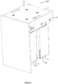
- a container apparatus (more particularly a waste container apparatus) according to an aspect of the invention is generally referenced by arrow 100.
- the apparatus comprises a bracket 1 which serves as a mounting means for the apparatus, and a frame 2 which is slidably connected to the bracket 1 by a sliding mechanism 3, preferably by extendable runners 40, 41 such as are known to the art.
- the mounting means may be configured to mount the container apparatus in a cavity (not shown).
- the cavity may form part of kitchen, laundry or garage cabinetry, for example.
- the frame 2 is adapted to support at least one container 4, preferably a waste container.
- the frame 2 is adapted to support two containers 4a, 4b, with a first container 4a positioned in front of a second container 4b.
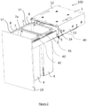
- FIG 2 is an isometric view of a retractable container apparatus 100 according to one embodiment of the invention.
- the retractable container apparatus 100 may comprise a front panel 19, sliding mechanism 3, and collars 42 as well as the bracket 1 and containers 4.
- Figure 2 shows two collars 42 each supporting a container 4 between the extendable runners 40, 41 of the sliding mechanism 3 and behind front panel 19.
- the front panel 19 may be configured to cover the front of the cavity when the sliding mechanism 3 is retracted.
- the front panel 19 is mounted on the front end of the sliding mechanism 3 such that moving the front panel 2 outwards also extends the sliding mechanism 3, thereby in use pulling the containers 4 out of the cavity.
- the bracket 1 may be adapted to be mounted within the cavity, for example to the walls of the cavity, and supports the sliding mechanism 3.
- front panel 19 may not be attached to the sliding mechanism 3. Instead front panel 19 may be mounted by a hinge mechanism to a part of the cabinetry such that, when closed, the front panel 19 covers the front of the cavity and can be rotatably opened to expose the cavity.
- a handle may be provided to the retractable container apparatus 100 such that pulling the handle will result in pulling the containers 4 out of the cavity.
- the handle may be attached directly or indirectly to the sliding mechanism 3.
- the sliding mechanism 3 of the embodiment in Figure 2 comprises two laterally spaced runners, each runner being slidingly engaged with the bracket 1 on opposing sides of the cavity so that, in use, each runner is positioned adjacent each lateral wall of the cavity.
- Each runner comprises a stationary runner member 40 in sliding engagement with a moving runner member 41.
- the stationary runner member 40 is configured to be secured to the bracket 1 such that, when the retractable container apparatus 100 is opened, the stationary runner member 40 remains in a fixed position on the bracket 1.
- the moving runner member 41 is configured to be attached to front panel 19 such that, when the retractable container apparatus 100 is opened, the moving runner member 41 extends out of the cavity and supports the collar(s) 42 and container(s) 4.
- the sliding mechanism 3 may be hard to clean and may be difficult to remove from the retractable container apparatus 100.
- the apparatus 100 comprises at least one lid 5 mounted to the bracket 1 by connecting means 6.
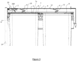
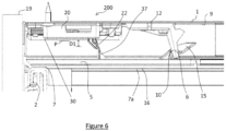
- the connecting means 6 are arranged such that the lid 5 can move from the first lid position (shown in Figures 3 and 6 ), wherein the lid 5 substantially covers the open end 8 of the container 4, and a second lid position (one example of which is shown in Figure 8 ) wherein there is no contact between the lid and the waste container or the frame.
- the lid 4 may contact an upper surface of the container 4 to cover the open end 8.
- the lid 5 may cover the open end 8 by contacting another member which is positioned on top of the container.
- the lid 5 covers the open end 8 by contacting a liner securing means 7 (in the form of a snap-fit collar in the embodiment shown) which is provided on top of the container 4 to hold a container liner (not shown) in position.
- a liner securing means 7 in the form of a snap-fit collar in the embodiment shown
- references to the upper surface of the container include reference to the upper surface of the liner securing means 7.
- the frame 2 is slidable between a first frame position (shown in Figure 3 ) wherein the lid 5 completely covers an open end 8 of the waste container(s), and a second frame position (not shown) which is offset from the first position in a first direction D.
- the offset is relatively small, for example around 10mm - 30mm.
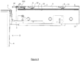
- Figure 4 shows the frame 2 offset in the first direction D, but having moved beyond a preferred example of the second position, as is described further below.
- the frame 2 is slideable from the first frame position to a further frame position wherein the or each container 4 is at least partially uncovered so that items can be placed in the container(s).
- Figures 2 and 4 show an example of the frame 2 in such a further frame position.
- the connecting means 6 preferably comprise a plurality of arms which are rotatably connected to the lower surface 9 of an upper wall 12 of the mounting means/bracket 1.
- the connecting means 6 preferably comprise at least a first arm 10 and a second arm 11, wherein the first arm 10 is offset from second arm 11 in the first direction D.
- the first and second arms 10, 11 are arranged to form a parallelogram linkage with the lid 5, such that the lid 5 can swing upward and in an opposite direction to the first direction D when moving from the first lid position to the second lid position.
- the first and second arms 10, 11 could be of different lengths such that the lid is tilted as it moves from the first lid position to the second lid position.
- the lid 5 is biased towards the first lid position by gravity.
- the bracket 1 preferably comprises an upper wall 12, side walls 13 and an open first end 14 from which the frame 2 extends when in the second frame position (and beyond).
- the opposite end of the bracket 1 may also be open.
- no bracket is provided and the internal surfaces of a cabinet may function as the mounting means.
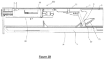
- connection between the lid 5 and the connecting means 6 is preferably releasable, for example the connection may be by hook means 15 connected to the lid 5 (best seen in Figures 6 , 8 and 10 ) which are adapted to engage hook receiving portions of the connecting means 6.
- This form of connection enables easy disconnection of the lid 5 from the connecting means 6 by lifting of the lid 5 and movement in the first direction D.
- the connecting means 6 may be provided with hook means which engage a suitable formation provided on the lid 5.
- a lid moving means is provided for moving the lid 5 to the second position when the frame 2 is moved from the first position to the second position (and beyond).
- the lid 5 is lifted away from contact with the containers 4 (and the frame) so that the containers 4 can be slid out from beneath the lid 5 without the lid dragging on the upper surface 7a of the containers.
- This may reduce wear of the lid 5 and/or may allow the lower surface 16 of the lid 5 to be made of a resilient material which provides a good seal with the upper surface 7a of the containers 4.
- Moving the lid 5 so that it does not drag against the containers 4 or other moving components may also make the frame easier to move back and forth than it would otherwise be, and may for example allow the use of "soft close”, “self close” or “push to open” runner mechanisms such as are well known to those skilled in the art.
- lid moving means 200 may comprise a sensing means (for example an optical or magnetic sensor) for sensing when the frame 2 moves from the first position to the second position, and an electrically operated actuator (for example a solenoid or a linear motor) to move the lid 5 from the first lid position to the second lid position.
- a sensing means for example an optical or magnetic sensor
- an electrically operated actuator for example a solenoid or a linear motor
- a lid moving means 200 is generally referenced by arrow 200.
- the lid moving means 200 comprises a housing 20 which comprises a base for the lid moving means 200.
- An actuation means 21 is provided which is slidably engaged with the housing 20.
- the actuation means 21 comprises a lid engaging means 22 which, in use, abuts an upstanding portion 37 of the lid 5.
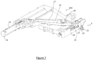
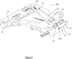
- the actuation means 21 is slidable between a first actuation means position, shown in Figures 5 and 6 , and a second actuation means position, shown in Figures 7 and 8 , which is offset from the first actuation means position in a direction opposite to direction D.
- actuation means 21 is preferably biased towards the second actuation means position by suitable biasing means such as a spring 23 which is positioned between an actuation member 29 and the housing 20.
- the lid moving means 200 is provided with an abutment means 24 which acts as a frame position detection means and determines when the actuation means 21 moves from the first actuation means position to the second actuation means position.
- the moving means 200 is provided with transmission means 25 which cause movement of the actuation means 21 from the second actuation means position to the first actuation means position when the distal end 26 of the abutment means 24 is pushed towards the housing 20 by a portion of the frame 2 (or a part connected to or otherwise arranged to move with the frame such as a front panel 19).
- Releasing the abutment means 24 allows the actuation means to move to the second actuation means position under the action of the biasing means 23.
- the transmission means 25 comprises a transmission member 27 which is engaged with the abutment means 24 at a first end 27A and engaged with the actuation means 21 at a second end 27B, and has a rotatable connection 28 to the housing 20 intermediate the first and second ends 27A, 27B.
- the distance between the second end 27B and the rotatable connection 28 is approximately 1 ⁇ 4 the total length of the transmission member 27, such that the actuation means 21 moves around 1mm for every 3mm of movement of the abutment means 24.
- alternative transmission means 25 may be used to cause movement of the actuation means 21 when the abutment means 24 is moved, for example a system of gears or the like.
- the lid moving means 200 is arranged such that the lid engaging means 22 is moveable to a third position which does not abut the lid 5, for example when a user wishes to remove the lid 5 for cleaning or other purposes.
- movement of the actuation means 21 between the first actuation means position and the second actuation means position is substantially linear, and causes movement of the lid engaging means 22 along a first axis A.
- movement of the actuation means 21 to the third actuation means position causes movement of the lid engaging means 22 to a third lid engaging means position which is offset from axis A.
- the lid engaging means 22 protrudes from a plane P of a lower surface 30 of the housing 20 by a distance D1.
- the lid engaging means 22 extends from the plane by a distance D2 which is smaller than D1.
- distance D2 may be zero, that is, the lid engaging means 22 may not extend at all from the housing 20 when the actuation means 21 is in the third position. Disengaging the lid engaging means 22 from the lid 5 in this way may make it possible, or easier, to disengage the lid 5 from the connecting means 6, as is described above.
- the actuation means 21 comprises an actuation member 29, and the lid engaging means 22 is rotatably connected to the actuation member 29.
- the lid engaging means 22 is preferably biased towards the extended position shown in Figures 6 and 8 . Movement of the actuation means 21 to the third actuation means position causes the lid engaging means 22 to come into contact with a lower wall of the housing 20, thereby causing the lid engaging means 22 to rotate around the rotational axis R (shown in Figure 5 ) so that the lid engaging means 22 no longer protrudes from housing 20, or protrudes only a small distance.
- the lid engaging means 22 may move so that it no longer protrudes from housing 20 by means other than rotation, for instance by sliding into the housing.
- the distal end 26 of the abutment means 24 enters the housing 20, or draws level with a protruding part of the housing 20, before the actuation means 21 extends significantly beyond the first actuation means position towards the third actuation means position. This prevents accidental movement of the actuation means 21 to the third actuation means position, which might result in accidental disengagement of the lid 5.
- the lid moving means 200 may be provided with a mechanism which allows movement of the actuation means 21 to the third actuation means position when required.
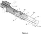
- the abutment means 24 has a normal configuration, shown in Figure 7 , and an extended configuration, shown in Figure 11 .
- the abutment means 24 comprises an inner member 31, which is connected to the transmission means 25, and an outer sleeve 32 which is rotatably and slidably connectable to the inner member 31.
- a side wall of the inner member 31 is provided with a protruding portion in the form of a pin or tab 33 which engages a slot 34 provided in the outer sleeve 32.
- the slot 34 has a first portion 35 which extends substantially parallel to a longitudinal axis of the inner member 31, and a second portion 36 which extends transversely from an end of the first portion 35 distal to the distal end 26 of the abutment means 24.
- the sleeve 32 is pulled outwardly (i.e. away from the housing) until the tab 33 reaches the end of the first portion 35 of the slot 34, and is then rotated such that the tab 33 engages the second portion 36 of the slot 34.
- the sleeve 32 can be used to push the inner member 31 beyond the point at which it enters the housing 20, and to the point at which the actuation means 21 moves to the third actuation means position.
- the sleeve 32 is preferably biased towards the normal configuration.
- the sleeve may be provided with an inwardly protruding tab and the inner member 31 with a corresponding slot.
- an outer sleeve may be connected to the transmission means and an inner member may be extended from the outer sleeve.
- the housing may be shaped to allow manual movement of the abutment means 24 to a position whereby the actuation means 21 extends beyond the first actuation means position to the third actuation means position.
- a lower portion of the housing may be provided with a slot which allows access for a user's finger to push the distal end 26 of the abutment means 24 inside the housing 20 to cause the actuation means 21 to move to the third actuation means position.
- a special tool 39 may be provided to allow the abutment means 24 to be pushed inside the housing to a suitable position.
- the end portion 38 of the abutment means 24 may be formed from a soft material, such as rubber, to lessen the noise when the front panel 19 contacts the abutment means 24.
- the end portion 38 may also be shaped to receive an end of the special tool 39.
- the end portion has a concave depression adapted to receive the end of the tool 39 in use.
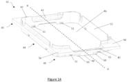
- Figure 14 is an isometric view of a collar 42 according to an embodiment of the invention and Figure 15 is a cross-sectional view of the collar 42, along the line A-A of Figure 14 .
- Collar 42 is adapted to connect to the sliding mechanism 3 to support a container 4 between the runners.
- the collar 42 is adapted to be easily removed, preferably without the use of additional tools, from the retractable container apparatus 100, as is described further below.
- the collar 42 may comprise three general portions: a body portion 44 and two wing portions 45. Each of the wing portions 45 are provided to opposing lateral sides of the body portion 44 (in the orientation of the collar when mounted in the retractable container apparatus 100), as shown in Figures 14 and 15 .
- the collar 42 defines opening 46, which is adapted to receive a container 4.
- the opening 46 may be positioned generally centrally in the collar 42 and may have a shape complementary to that of the container 4.
- the body portion 44 may at least partly define the collar opening 46 for the container 4. That is, the body portion 44 may entirely define the collar opening 46 or, as in the embodiment shown, the opening 46 may also be defined by the wing portions 45.
- the collar 42 may comprise one or more lift-out recesses 43, as shown in Figure 14 , in order that the container 4 may be easily removed from the apparatus 100.
- the lift-out recesses 43 may be provided in an upper surface of the collar 42 and may be of an appropriate size and shape such that a user can easily fit their fingers under an upper lip of a container which is supported by the collar to lift the container 4 up out of the collar 42.
- the collar 42 comprises one or more raised edges or ridges 47 projecting upwardly from the body portion 44 around the perimeter of the opening 46 on one or more sides of the opening 46.
- the ridges 47 are adapted to aid in supporting the container 4 and ensure a secure fit between the container 4 and the collar 42.
- the container 4 has a flange 57 around the rim of the top of the container 4. This flange 57 is adapted to engage with the one or more ridges 47 on the collar 42.
- the flange 57 may comprise a lip which fits over the ridges 47, so holding the container 4 securely in place relative to the collar 42.
- one or more collar opening recesses may be provided to the collar 42 around the opening 46. These collar opening recesses may have a shape complementary to that of the top of the container 4 and may be configured to receive the container 4 and hold it securely in place relative to the collar 42.
- the container 4 has a flange 57 around its upper rim and the collar opening recesses may be configured to receive the flange 57 of the container 4.
- the collar opening recesses provide the advantage that, when the flange 57 of the container 4 is received in the collar opening recesses, the top of the container 4 may be flush with, or below the upper surface of the collar 42 around the collar opening recesses.
- the collar opening recesses may also be configured to receive a handle on an upper part of the container 4, e.g. attached to the flange 57. This ensures that the handle (if provided) does not interfere with other parts of the retractable container apparatus 100 or obstruct the sliding mechanism 3 from closing.
- the wing portions 45 of collar 42 comprise a snap fit connector configured to connect the collar 42 directly or indirectly to the runners of sliding mechanism 3 via a snap fit connection.
- the collar 42 may be able to be lifted away from the sliding mechanism 3 by providing enough force to overcome the snap fit connection.
- the collar 42 connects directly to the moving runner members 41 of the sliding mechanism 3.
- the collar 42 connects indirectly to the sliding mechanism 3 by connecting directly to a cover member 48, the cover member 48 being mounted on the moving runner member 41, as best seen in Figure 17 .
- the collar 42 may directly connect to some other intermediate component(s) which is/are attached to the moving runner members 41 of sliding mechanism 3. It will be appreciated that the principles of the snap fit connection described herein between the collar 42 and cover member 48 may be applied to these other embodiments.
- the snap fit connection between the collar 42 and the sliding mechanism 3 may comprise one or more snap fit connectors on an outer surface 49 of the collar 42, for example on an outer lateral surface facing the sliding mechanism 3, and a structure on the sliding mechanism 3 configured to receive the snap fit connectors such as is described below.
- a snap fit connector is provided on each of the wing portions 45, to connect both wing portions 45 to the sliding mechanism 3.
- a snap fit connector is provided to only one of the wing portions 45.
- the snap fit connectors comprise one or more protrusions 50 on the outer lateral surface 49 of the wing portions 45.
- two protrusions 50 are spaced along each outer lateral surface 49 of the wing portions 45.
- the protrusions 50 comprise an upper sloping surface and a horizontal lower surface.
- the collar 42 may further comprise one or more projections 51 on the inner surface 52 of the opening 46 of the body portion 44. Projections 51 may be provided on opposing lateral sides of the opening 46. In the embodiment shown in Figure 14 the projections 51 are positioned and arranged so that, when the container 4 is placed in the opening 46, the container 4 contacts the projections 51.
- the sides of the container 4 inhibit the inward movement (for example by flexure) of portions of the collar 42 around opening 46. This inhibits the protrusions 50 of the snap fit connectors from moving inwardly and therefore disengaging with the snap fit connector portion to which it connects. This keeps the collar 42 securely in place in use when a container is mounted to the collar.
- the container 4 and collar 42 are structured and configured such that, when the container 4 contacts the projections 51, the protrusions 50 of snap fit connectors are urged in an outward lateral direction.
- the body portion 44 may be deformed, thus pushing the protrusions outwardly.
- the container 4 may be configured to be tapered such that the outer perimeter at the top of the container 4 is larger than the outer perimeter at the base of the container 4, as shown in Figure 18 . This makes it easier to place the bottom of the container 4 in the opening 46 and, as the container 4 is lowered into the collar 42, the sides of the container 4 come into contact with the projections 51. As the container 4 is lowered further into the collar 42 the body portion 44 is deformed as explained above.
- the collar 42 may be constructed of a deformable material, for example a plastics material, so that it can deform in the manner described. Tapered containers may also be used with any of other embodiments of the collar described above.
- a cover member 48 may be provided to each of the moving runner members 41 of the sliding mechanism 3.
- the cover member 48 may be mounted to the respective moving runner member 41 along a substantial part of its length.
- the cover member 48 may be configured to cover the sliding mechanism 3, as shown in Figure 17 , which helps in preventing dirt accumulating on or around the runners.
- the cover member 48 may comprise two portions: a runner cover portion 53 which is generally inverted u-shaped and covers the runners; and a snap fit connector portion 54 which is provided above the runner cover portion 53 and is configured to connect to the collar 42 in a snap fit connection.
- the cover member 48 may be formed from any suitable material, such as aluminium, roll formed steel, plastic or wood.
- the snap fit connector portion 54 of cover member 48 may comprise one or more grooves 55 configured to receive the protrusion(s) 50 of the wing portion 45 of collar 42.
- the groove 55 may have a shape complementary to that of the protrusion 50 to assist this engagement.
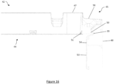
- Figure 16 is an enlarged cross-sectional view of part of the collar 42 and cover member 48 of the apparatus shown in Figure 2 .
- the cover member 48 has a groove 55 with two sloping surfaces, the upper sloping surface being on the same angle as the upper surface of the protrusions 50 to provide a firm engagement between these components when the upper surface of the groove 55 contacts the upper surface of the protrusions 50.
- the groove 55 may be provided directly to the moving runner member 41, therefore having a direct connection between the sliding mechanism 3 and the collar 42.
- Figure 17 is an enlarged cross-sectional view of part of the apparatus shown in Figure 2 .
- the cover member 48 covers the sliding mechanism 3 and is connected to the collar 42 via the snap fit connection.
- the cover member 48 may be configured to attach to the sliding mechanism 3 such that it moves concurrently with the sliding mechanism 3.
- the collar 42 may be configured to cover at least a part of the sliding mechanism 3, for example the moving runner members 41.
- the wing portions 45 may comprise cover portions 56 extending laterally outwardly from body portion 44.
- the cover portions 56 may be configured to cover parts of the sliding mechanism 3, for example those parts that are exposed during opening of the retractable container apparatus 100, thereby preventing or hindering accumulation of dirt and dust.
- the cover portions 56 may directly cover the sliding mechanism 3 or alternatively indirectly cover the sliding mechanism 3, for example by covering cover member 48 which is mounted on the moving runner members 41, as shown in Figure 17 .
- the cover portions 56 preferably comprise a substantially planar upwardly facing surface, which may be easily cleaned.
- the snap fit connection when the collar 42 is fitted to the sliding mechanism 3 via the snap fit connection, the snap fit connection is fully engaged, i.e. the snap fit connector or protrusions 50 are substantially fully interlocked with the complementary grooves 55. in this position the protrusions 50 may be securely fitted and may not move any further laterally outwardly.
- the container 4 When the container 4 is fitted into the collar 42 it contacts the projections 51. This contact prevents the snap fit connection from disengaging by inhibiting the collar 42, and therefore the snap fit connector or protrusions 50, from moving inwardly (i.e. towards opening 46) and disconnecting from the grooves 55. This aids in ensuring the protrusions 50 remain in secure contact with the grooves 55.
- Figure 18 is a further cross-sectional view of the retractable container system shown in Figure 2 . As shown in Figure 18 , when the projections 51 are in contact with the container 4, the protrusions 50 of the snap fit connection are pushed outwardly into the groove 55.
- the opening 46 of the collar 42 may be of a size complementary to that of the container 4 such that, when the container 4 is placed in the opening 46, the sides of the container 4 contact the area of the collar 42 forming the opening 46. This contact prevents the snap fit connection from disengaging in a similar manner to that described above.
- the opening 46 of the collar 42 may be of a size that is slightly smaller than the perimeter of container 4 such that, when the container 4 is fitted in the opening 46, the opening 46 is deformed and wing portions 45 are urged in an outward lateral direction, strengthening the snap fit connection in a similar manner to that described above.
- the opening 46 may not be necessary to have projections 51 on the collar 42, as the shape and size of the collar 42 would achieve a similar enhancement of the snap fit connection.
- the collar 42 may be removed from the retractable container apparatus 100 by releasing the snap fit connection.
- the snap fit connection may be released by pulling the collar 42 inwardly at the edges of the opening 46 to disengage the snap fit connector or protrusion 50 from the groove 55.
- the collar 42 may be able to be twisted to remove it.
- the easy removal of the collar 42 assists with cleaning the collar and also enables the collar 42 to be placed in a dishwasher or other automatic washing or sanitizing machine. The collar is therefore easily and quickly cleaned and maintained.
- the collar 42 may have more than one opening 46 and may be configured to support more than one container 4.
- multiple collars 42 may be configured to be mounted on the same sliding mechanism 3, each supporting a container 4. In such forms the collar or collars together may be configured to substantially cover the sliding mechanism 3 to protect the sliding mechanism 3 from accumulating dirt.
- two collars 42 are adjacent to each other and both are supported by the sliding mechanism 3.
- One of the collars 42 is positioned adjacent to the front panel 19, the other collar 42 being positioned directly behind. This enables the containers 4 to be suspended longitudinally adjacent within the cavity.
- Alternative embodiments may use different configurations of multiple collars 42, depending on the desired design and layout of the containers.
- the retractable container apparatus 100 may be provided in a kitchen and container 4 may be used for storing waste. In other examples, container apparatus 100 may be provided in a garage and containers 4 may be used for storing laundry or other items.
- another elongate member may be used in place of the cover member 48 of the illustrated embodiments. That is, embodiments of the technology are not limited to this component being formed from an extruded length of material.
- the snap fit connection may comprise a groove provided to the collar 42 and a protrusion 50 provided to the moving runner member 41 or cover member 48 (i.e. the 'male' and 'female' members of the snap fit connection are swapped around from the embodiment described with reference to the figures).
- the snap fit connection would still work in a similar method as described above to connect the collar 42 to the retractable container apparatus 100.
- Alternative embodiments may use other forms of snap fit connection.
Landscapes
- Engineering & Computer Science (AREA)
- Mechanical Engineering (AREA)
- Closures For Containers (AREA)
- Refuse Receptacles (AREA)
- Drawers Of Furniture (AREA)
- Auxiliary Devices For And Details Of Packaging Control (AREA)
- Supplying Of Containers To The Packaging Station (AREA)
Priority Applications (1)
| Application Number | Priority Date | Filing Date | Title |
|---|---|---|---|
| EP22216401.4A EP4212066A1 (en) | 2017-10-13 | 2018-10-12 | A container apparatus and a container mounting collar |
Applications Claiming Priority (3)
| Application Number | Priority Date | Filing Date | Title |
|---|---|---|---|
| NZ73628317 | 2017-10-13 | ||
| NZ73629017 | 2017-10-13 | ||
| PCT/NZ2018/050140 WO2019074381A1 (en) | 2017-10-13 | 2018-10-12 | CONTAINER APPARATUS AND CONTAINER MOUNTING COLLAR |
Related Child Applications (2)
| Application Number | Title | Priority Date | Filing Date |
|---|---|---|---|
| EP22216401.4A Division-Into EP4212066A1 (en) | 2017-10-13 | 2018-10-12 | A container apparatus and a container mounting collar |
| EP22216401.4A Division EP4212066A1 (en) | 2017-10-13 | 2018-10-12 | A container apparatus and a container mounting collar |
Publications (4)
| Publication Number | Publication Date |
|---|---|
| EP3627990A1 EP3627990A1 (en) | 2020-04-01 |
| EP3627990A4 EP3627990A4 (en) | 2021-03-03 |
| EP3627990B1 true EP3627990B1 (en) | 2023-06-07 |
| EP3627990C0 EP3627990C0 (en) | 2023-06-07 |
Family
ID=66101426
Family Applications (2)
| Application Number | Title | Priority Date | Filing Date |
|---|---|---|---|
| EP18866970.9A Active EP3627990B1 (en) | 2017-10-13 | 2018-10-12 | A container apparatus |
| EP22216401.4A Withdrawn EP4212066A1 (en) | 2017-10-13 | 2018-10-12 | A container apparatus and a container mounting collar |
Family Applications After (1)
| Application Number | Title | Priority Date | Filing Date |
|---|---|---|---|
| EP22216401.4A Withdrawn EP4212066A1 (en) | 2017-10-13 | 2018-10-12 | A container apparatus and a container mounting collar |
Country Status (9)
| Country | Link |
|---|---|
| US (2) | US11691811B2 (cg-RX-API-DMAC7.html) |
| EP (2) | EP3627990B1 (cg-RX-API-DMAC7.html) |
| JP (2) | JP2020536826A (cg-RX-API-DMAC7.html) |
| KR (1) | KR102633712B1 (cg-RX-API-DMAC7.html) |
| CN (1) | CN111225586B (cg-RX-API-DMAC7.html) |
| AU (2) | AU2018348585B2 (cg-RX-API-DMAC7.html) |
| CA (1) | CA3076417A1 (cg-RX-API-DMAC7.html) |
| ES (1) | ES2949981T3 (cg-RX-API-DMAC7.html) |
| WO (1) | WO2019074381A1 (cg-RX-API-DMAC7.html) |
Families Citing this family (2)
| Publication number | Priority date | Publication date | Assignee | Title |
|---|---|---|---|---|
| CN116902292B (zh) * | 2023-08-10 | 2025-08-08 | 深圳市朗科智能电气股份有限公司 | 一种真空打包装置 |
| DE202024100309U1 (de) * | 2024-01-22 | 2025-04-24 | Ninkaplast Gmbh | Tragevorrichtung zum Tragen von Behältern in einem Möbelauszug |
Family Cites Families (37)
| Publication number | Priority date | Publication date | Assignee | Title |
|---|---|---|---|---|
| US3528718A (en) * | 1967-12-01 | 1970-09-15 | Harold J Johnson | Garbage can and support |
| DE3008934C2 (de) * | 1980-03-08 | 1983-01-05 | Hailo-Werk Rudolf Loh Gmbh & Co Kg, 6342 Haiger | Abfallsammler aus einem Füllbehälter und einem Deckel |
| DE3631276C1 (en) * | 1986-09-03 | 1988-02-25 | Noss Kuechentechnik Gmbh | Refuse collector with a lid which can be lifted by spring force |
| SE467339B (sv) * | 1990-10-29 | 1992-07-06 | Sari Scheinberg Med Firma Sari | Insatsstycke foer skaap |
| DE9107138U1 (de) | 1991-06-10 | 1991-07-25 | Bulthaup GmbH & Co, 8318 Aich | Abfallsammelvorrichtung mit Geruchsverschluß mit einem Auszug zur Aufnahme eines Abfalleimers mit Deckel |
| DE9200360U1 (de) * | 1992-01-15 | 1993-05-13 | Grass Holding AG, Höchst | Müllbehälter mit Geruchsverschluß |
| DE9414004U1 (de) * | 1993-10-11 | 1995-02-16 | Hailo-Werk Rudolf Loh GmbH & Co KG, 35708 Haiger | Träger für Abfallsammler |
| US5634702A (en) * | 1995-09-27 | 1997-06-03 | Fistonich; Juraj | Hands free waste container having a closed cover that automatically opens when the container is moved outside its cabinet enclosure |
| DE29519539U1 (de) * | 1995-12-09 | 1997-04-17 | Ninkaplast GmbH, 32108 Bad Salzuflen | Abfallsammler |
| DE19920388A1 (de) * | 1999-05-04 | 2000-11-30 | Loh Kg Hailo Werk | Anordnung zur Herstellung eines Rahmenbauteils sowie Möbelbauteil umfassend ein solches Rahmenbauteil |
| JP2001087059A (ja) | 1999-09-17 | 2001-04-03 | Beltecno Corp | システムキッチン用キャビネット |
| US20020024276A1 (en) | 2000-03-23 | 2002-02-28 | Egbert Neuhaus | Drawer which is incorporated in a cupboard, in particular kitchen cupboard drawer |
| JP2002355132A (ja) * | 2001-03-27 | 2002-12-10 | Matsushita Electric Works Ltd | 厨房組み込み型生ごみ処理装置 |
| US7370919B2 (en) | 2003-07-07 | 2008-05-13 | Peter Meier, Inc. | Waste container with hidden slides |
| JP4182943B2 (ja) * | 2004-11-01 | 2008-11-19 | 松下電工株式会社 | 換気付き収納容器装置 |
| ES1059455Y (es) * | 2005-01-31 | 2005-08-01 | Apolo Comunicaciones S L | Soporte para bolsas |
| JP4655720B2 (ja) * | 2005-03-29 | 2011-03-23 | パナソニック電工株式会社 | 蓋付き収納容器装置 |
| DE202005016305U1 (de) * | 2005-04-29 | 2006-08-31 | Westermann Kg | In einem Schrank aufgenommene Schublade |
| DE202005008286U1 (de) * | 2005-05-27 | 2006-10-05 | Paul Hettich Gmbh & Co. Kg | Schubkasten |
| US7607444B2 (en) | 2005-11-29 | 2009-10-27 | Maytag Corporation | Latching and sealing mechanism for a drawer-type dishwasher |
| DE202006001172U1 (de) | 2005-11-30 | 2007-04-12 | Westermann Kg | Abfallsammler-Auszugvorrichtung |
| US20080007147A1 (en) | 2006-02-02 | 2008-01-10 | Skog David V | Waste container apparatus |
| CA2642062A1 (en) * | 2007-10-25 | 2009-04-25 | Rehrig Pacific Company | Container |
| US8201570B2 (en) * | 2009-10-23 | 2012-06-19 | General Electric Company | Dishwasher drawer gasket system |
| AT509412A1 (de) | 2010-02-05 | 2011-08-15 | Blum Gmbh Julius | Möbelauszug |
| ITBO20120007U1 (it) * | 2012-01-27 | 2013-07-28 | Romagna Plastic S R L | Cassetto per la raccolta differenziata dei rifiuti |
| DE102012103103A1 (de) | 2012-04-11 | 2013-10-17 | Westermann Kg | Zargen-Abdeckleiste und Schublade |
| EP2801291A1 (de) * | 2013-05-10 | 2014-11-12 | Vauth-Sagel Holding GmbH & Co. KG | Möbelbeschlag zur Ausbildung einer ausziehbaren Abfallsammelvorrichtung |
| US8978917B2 (en) * | 2013-06-30 | 2015-03-17 | 1908 Brands, Inc. | Waste containment receptacle |
| US20150008813A1 (en) * | 2013-07-08 | 2015-01-08 | Thomas Braun | Top mount adjustable cabinet mounted frame |
| US9049930B1 (en) * | 2013-12-27 | 2015-06-09 | Rev-A-Shelf Company, Llc | Cabinet drawer floor and fence assembly |
| DE202014102726U1 (de) * | 2014-06-12 | 2015-09-15 | Ninkaplast Gmbh | Einhängerahmen für Abfallbehälter in Möbelauszügen |
| US9587761B2 (en) * | 2014-10-29 | 2017-03-07 | GM Global Technology Operations LLC | Multi-position actuator |
| DE202015100485U1 (de) * | 2015-02-02 | 2016-05-03 | Ninkaplast Gmbh | Bausatz für den Einbau eines Positionierungsrahmens in einen Möbelauszug |
| EP3072415B1 (de) * | 2015-03-25 | 2018-03-07 | Vauth-Sagel Holding GmbH & Co. KG | Möbelbeschlag zur ausbildung einer ausziehbaren abfallsammelvorrichtung und schrank mit einem solchen möbelbeschlag |
| DE202017102855U1 (de) * | 2017-05-12 | 2018-08-23 | Westermann Kg | Schublade, vorzugsweise ohne Boden und für einen Küchenschrank |
| CN210785134U (zh) * | 2018-11-02 | 2020-06-19 | 苏州大学附属第二医院 | 一种多功能医用护理治疗车 |
-
2018
- 2018-10-12 CA CA3076417A patent/CA3076417A1/en active Pending
- 2018-10-12 US US16/635,385 patent/US11691811B2/en active Active
- 2018-10-12 WO PCT/NZ2018/050140 patent/WO2019074381A1/en not_active Ceased
- 2018-10-12 JP JP2020541637A patent/JP2020536826A/ja active Pending
- 2018-10-12 CN CN201880066449.4A patent/CN111225586B/zh active Active
- 2018-10-12 ES ES18866970T patent/ES2949981T3/es active Active
- 2018-10-12 EP EP18866970.9A patent/EP3627990B1/en active Active
- 2018-10-12 EP EP22216401.4A patent/EP4212066A1/en not_active Withdrawn
- 2018-10-12 KR KR1020207004003A patent/KR102633712B1/ko active Active
- 2018-10-12 AU AU2018348585A patent/AU2018348585B2/en active Active
-
2023
- 2023-02-15 US US18/110,089 patent/US12612247B2/en active Active
- 2023-06-20 AU AU2023203864A patent/AU2023203864B2/en active Active
- 2023-07-20 JP JP2023118375A patent/JP7546117B2/ja active Active
Also Published As
| Publication number | Publication date |
|---|---|
| ES2949981T3 (es) | 2023-10-04 |
| JP2020536826A (ja) | 2020-12-17 |
| US12612247B2 (en) | 2026-04-28 |
| CA3076417A1 (en) | 2019-04-18 |
| AU2018348585B2 (en) | 2023-06-29 |
| NZ762516A (en) | 2026-01-30 |
| AU2023203864B2 (en) | 2025-08-28 |
| US20230322481A1 (en) | 2023-10-12 |
| CN111225586A (zh) | 2020-06-02 |
| EP3627990C0 (en) | 2023-06-07 |
| JP7546117B2 (ja) | 2024-09-05 |
| EP3627990A1 (en) | 2020-04-01 |
| AU2018348585A1 (en) | 2020-04-02 |
| KR102633712B1 (ko) | 2024-02-02 |
| EP3627990A4 (en) | 2021-03-03 |
| NZ802664A (en) | 2026-01-30 |
| EP4212066A1 (en) | 2023-07-19 |
| JP2023139136A (ja) | 2023-10-03 |
| CN111225586B (zh) | 2022-06-03 |
| AU2023203864A1 (en) | 2023-07-13 |
| US11691811B2 (en) | 2023-07-04 |
| WO2019074381A1 (en) | 2019-04-18 |
| KR20200064979A (ko) | 2020-06-08 |
| US20200156866A1 (en) | 2020-05-21 |
Similar Documents
| Publication | Publication Date | Title |
|---|---|---|
| JP7546117B2 (ja) | コンテナ装置とコンテナ取付け襟部 | |
| EP2142448B1 (en) | Container and towel dispensing system | |
| EP2785944B1 (en) | Roller assembly for a folding door system | |
| US20100219192A1 (en) | Dividable step garbage can | |
| WO2020210577A1 (en) | Device to open and close trash bin cabinet doors in small spaces | |
| JP3593520B2 (ja) | キャビネット | |
| KR102173768B1 (ko) | 벽걸이형 쓰레기통 | |
| JP7297233B2 (ja) | キャビネット | |
| JP4179930B2 (ja) | 食器洗浄機 | |
| KR20100009956U (ko) | 다용도 신발장 | |
| CN223779100U (zh) | 一种橱柜侧边收纳筐 | |
| KR101371404B1 (ko) | 음식물쓰레기수거함용 뚜껑지지대 및 이를 이용한 음식물쓰레기수거함 | |
| JP5611073B2 (ja) | 収納庫 | |
| KR200329214Y1 (ko) | 코너 싱크대 선반의 슬라이딩 인출장치 | |
| KR20250108157A (ko) | 식기건조기의 선반자동인출장치 | |
| CN202226294U (zh) | 一种新型脚踏掀盖式垃圾桶 | |
| AU2003100476A4 (en) | Drawer bins unit | |
| GB2478540A (en) | Device to prevent jamming of drawers and the loss of items behind a rear wall | |
| JPH04116928U (ja) | 台所用包丁ケース | |
| CN104602567A (zh) | 家具的搁物架的滑动和枢转机构、家具和家用器具 |
Legal Events
| Date | Code | Title | Description |
|---|---|---|---|
| STAA | Information on the status of an ep patent application or granted ep patent |
Free format text: STATUS: THE INTERNATIONAL PUBLICATION HAS BEEN MADE |
|
| PUAI | Public reference made under article 153(3) epc to a published international application that has entered the european phase |
Free format text: ORIGINAL CODE: 0009012 |
|
| STAA | Information on the status of an ep patent application or granted ep patent |
Free format text: STATUS: REQUEST FOR EXAMINATION WAS MADE |
|
| 17P | Request for examination filed |
Effective date: 20191223 |
|
| AK | Designated contracting states |
Kind code of ref document: A1 Designated state(s): AL AT BE BG CH CY CZ DE DK EE ES FI FR GB GR HR HU IE IS IT LI LT LU LV MC MK MT NL NO PL PT RO RS SE SI SK SM TR |
|
| AX | Request for extension of the european patent |
Extension state: BA ME |
|
| DAV | Request for validation of the european patent (deleted) | ||
| DAX | Request for extension of the european patent (deleted) | ||
| A4 | Supplementary search report drawn up and despatched |
Effective date: 20210201 |
|
| RIC1 | Information provided on ipc code assigned before grant |
Ipc: A47B 88/00 20170101ALN20210126BHEP Ipc: B65F 1/14 20060101ALI20210126BHEP Ipc: A47B 77/18 20060101AFI20210126BHEP Ipc: B65F 1/16 20060101ALI20210126BHEP |
|
| GRAP | Despatch of communication of intention to grant a patent |
Free format text: ORIGINAL CODE: EPIDOSNIGR1 |
|
| STAA | Information on the status of an ep patent application or granted ep patent |
Free format text: STATUS: GRANT OF PATENT IS INTENDED |
|
| RIC1 | Information provided on ipc code assigned before grant |
Ipc: A47B 88/00 20170101ALN20211021BHEP Ipc: B65F 1/16 20060101ALI20211021BHEP Ipc: B65F 1/14 20060101ALI20211021BHEP Ipc: A47B 77/18 20060101AFI20211021BHEP |
|
| RIC1 | Information provided on ipc code assigned before grant |
Ipc: A47B 88/00 20170101ALN20211105BHEP Ipc: B65F 1/16 20060101ALI20211105BHEP Ipc: B65F 1/14 20060101ALI20211105BHEP Ipc: A47B 77/18 20060101AFI20211105BHEP |
|
| INTG | Intention to grant announced |
Effective date: 20211122 |
|
| GRAJ | Information related to disapproval of communication of intention to grant by the applicant or resumption of examination proceedings by the epo deleted |
Free format text: ORIGINAL CODE: EPIDOSDIGR1 |
|
| STAA | Information on the status of an ep patent application or granted ep patent |
Free format text: STATUS: REQUEST FOR EXAMINATION WAS MADE |
|
| INTC | Intention to grant announced (deleted) | ||
| GRAP | Despatch of communication of intention to grant a patent |
Free format text: ORIGINAL CODE: EPIDOSNIGR1 |
|
| STAA | Information on the status of an ep patent application or granted ep patent |
Free format text: STATUS: GRANT OF PATENT IS INTENDED |
|
| RIC1 | Information provided on ipc code assigned before grant |
Ipc: A47B 88/00 20170101ALN20220721BHEP Ipc: B65F 1/16 20060101ALI20220721BHEP Ipc: B65F 1/14 20060101ALI20220721BHEP Ipc: A47B 77/18 20060101AFI20220721BHEP |
|
| INTG | Intention to grant announced |
Effective date: 20220824 |
|
| GRAS | Grant fee paid |
Free format text: ORIGINAL CODE: EPIDOSNIGR3 |
|
| RAP3 | Party data changed (applicant data changed or rights of an application transferred) |
Owner name: BLUEWATER RISE INVESTMENTS LIMITED |
|
| GRAA | (expected) grant |
Free format text: ORIGINAL CODE: 0009210 |
|
| STAA | Information on the status of an ep patent application or granted ep patent |
Free format text: STATUS: THE PATENT HAS BEEN GRANTED |
|
| AK | Designated contracting states |
Kind code of ref document: B1 Designated state(s): AL AT BE BG CH CY CZ DE DK EE ES FI FR GB GR HR HU IE IS IT LI LT LU LV MC MK MT NL NO PL PT RO RS SE SI SK SM TR |
|
| REG | Reference to a national code |
Ref country code: GB Ref legal event code: FG4D |
|
| REG | Reference to a national code |
Ref country code: CH Ref legal event code: EP Ref country code: AT Ref legal event code: REF Ref document number: 1572146 Country of ref document: AT Kind code of ref document: T Effective date: 20230615 |
|
| REG | Reference to a national code |
Ref country code: DE Ref legal event code: R096 Ref document number: 602018051571 Country of ref document: DE |
|
| U01 | Request for unitary effect filed |
Effective date: 20230704 |
|
| U07 | Unitary effect registered |
Designated state(s): AT BE BG DE DK EE FI FR IT LT LU LV MT NL PT SE SI Effective date: 20230717 |
|
| REG | Reference to a national code |
Ref country code: LT Ref legal event code: MG9D |
|
| REG | Reference to a national code |
Ref country code: ES Ref legal event code: FG2A Ref document number: 2949981 Country of ref document: ES Kind code of ref document: T3 Effective date: 20231004 |
|
| PG25 | Lapsed in a contracting state [announced via postgrant information from national office to epo] |
Ref country code: NO Free format text: LAPSE BECAUSE OF FAILURE TO SUBMIT A TRANSLATION OF THE DESCRIPTION OR TO PAY THE FEE WITHIN THE PRESCRIBED TIME-LIMIT Effective date: 20230907 |
|
| PG25 | Lapsed in a contracting state [announced via postgrant information from national office to epo] |
Ref country code: RS Free format text: LAPSE BECAUSE OF FAILURE TO SUBMIT A TRANSLATION OF THE DESCRIPTION OR TO PAY THE FEE WITHIN THE PRESCRIBED TIME-LIMIT Effective date: 20230607 Ref country code: HR Free format text: LAPSE BECAUSE OF FAILURE TO SUBMIT A TRANSLATION OF THE DESCRIPTION OR TO PAY THE FEE WITHIN THE PRESCRIBED TIME-LIMIT Effective date: 20230607 Ref country code: GR Free format text: LAPSE BECAUSE OF FAILURE TO SUBMIT A TRANSLATION OF THE DESCRIPTION OR TO PAY THE FEE WITHIN THE PRESCRIBED TIME-LIMIT Effective date: 20230908 |
|
| U20 | Renewal fee for the european patent with unitary effect paid |
Year of fee payment: 6 Effective date: 20231026 |
|
| PG25 | Lapsed in a contracting state [announced via postgrant information from national office to epo] |
Ref country code: SK Free format text: LAPSE BECAUSE OF FAILURE TO SUBMIT A TRANSLATION OF THE DESCRIPTION OR TO PAY THE FEE WITHIN THE PRESCRIBED TIME-LIMIT Effective date: 20230607 |
|
| PG25 | Lapsed in a contracting state [announced via postgrant information from national office to epo] |
Ref country code: IS Free format text: LAPSE BECAUSE OF FAILURE TO SUBMIT A TRANSLATION OF THE DESCRIPTION OR TO PAY THE FEE WITHIN THE PRESCRIBED TIME-LIMIT Effective date: 20231007 |
|
| PG25 | Lapsed in a contracting state [announced via postgrant information from national office to epo] |
Ref country code: SM Free format text: LAPSE BECAUSE OF FAILURE TO SUBMIT A TRANSLATION OF THE DESCRIPTION OR TO PAY THE FEE WITHIN THE PRESCRIBED TIME-LIMIT Effective date: 20230607 Ref country code: SK Free format text: LAPSE BECAUSE OF FAILURE TO SUBMIT A TRANSLATION OF THE DESCRIPTION OR TO PAY THE FEE WITHIN THE PRESCRIBED TIME-LIMIT Effective date: 20230607 Ref country code: RO Free format text: LAPSE BECAUSE OF FAILURE TO SUBMIT A TRANSLATION OF THE DESCRIPTION OR TO PAY THE FEE WITHIN THE PRESCRIBED TIME-LIMIT Effective date: 20230607 Ref country code: IS Free format text: LAPSE BECAUSE OF FAILURE TO SUBMIT A TRANSLATION OF THE DESCRIPTION OR TO PAY THE FEE WITHIN THE PRESCRIBED TIME-LIMIT Effective date: 20231007 Ref country code: CZ Free format text: LAPSE BECAUSE OF FAILURE TO SUBMIT A TRANSLATION OF THE DESCRIPTION OR TO PAY THE FEE WITHIN THE PRESCRIBED TIME-LIMIT Effective date: 20230607 |
|
| PG25 | Lapsed in a contracting state [announced via postgrant information from national office to epo] |
Ref country code: PL Free format text: LAPSE BECAUSE OF FAILURE TO SUBMIT A TRANSLATION OF THE DESCRIPTION OR TO PAY THE FEE WITHIN THE PRESCRIBED TIME-LIMIT Effective date: 20230607 |
|
| REG | Reference to a national code |
Ref country code: DE Ref legal event code: R097 Ref document number: 602018051571 Country of ref document: DE |
|
| PLBE | No opposition filed within time limit |
Free format text: ORIGINAL CODE: 0009261 |
|
| STAA | Information on the status of an ep patent application or granted ep patent |
Free format text: STATUS: NO OPPOSITION FILED WITHIN TIME LIMIT |
|
| 26N | No opposition filed |
Effective date: 20240308 |
|
| PG25 | Lapsed in a contracting state [announced via postgrant information from national office to epo] |
Ref country code: MC Free format text: LAPSE BECAUSE OF FAILURE TO SUBMIT A TRANSLATION OF THE DESCRIPTION OR TO PAY THE FEE WITHIN THE PRESCRIBED TIME-LIMIT Effective date: 20230607 |
|
| REG | Reference to a national code |
Ref country code: CH Ref legal event code: PL |
|
| PG25 | Lapsed in a contracting state [announced via postgrant information from national office to epo] |
Ref country code: CH Free format text: LAPSE BECAUSE OF NON-PAYMENT OF DUE FEES Effective date: 20231031 |
|
| PG25 | Lapsed in a contracting state [announced via postgrant information from national office to epo] |
Ref country code: CH Free format text: LAPSE BECAUSE OF NON-PAYMENT OF DUE FEES Effective date: 20231031 |
|
| PG25 | Lapsed in a contracting state [announced via postgrant information from national office to epo] |
Ref country code: IE Free format text: LAPSE BECAUSE OF NON-PAYMENT OF DUE FEES Effective date: 20231012 |
|
| PG25 | Lapsed in a contracting state [announced via postgrant information from national office to epo] |
Ref country code: IE Free format text: LAPSE BECAUSE OF NON-PAYMENT OF DUE FEES Effective date: 20231012 |
|
| U20 | Renewal fee for the european patent with unitary effect paid |
Year of fee payment: 7 Effective date: 20241025 |
|
| PG25 | Lapsed in a contracting state [announced via postgrant information from national office to epo] |
Ref country code: CY Free format text: LAPSE BECAUSE OF FAILURE TO SUBMIT A TRANSLATION OF THE DESCRIPTION OR TO PAY THE FEE WITHIN THE PRESCRIBED TIME-LIMIT; INVALID AB INITIO Effective date: 20181012 |
|
| PG25 | Lapsed in a contracting state [announced via postgrant information from national office to epo] |
Ref country code: HU Free format text: LAPSE BECAUSE OF FAILURE TO SUBMIT A TRANSLATION OF THE DESCRIPTION OR TO PAY THE FEE WITHIN THE PRESCRIBED TIME-LIMIT; INVALID AB INITIO Effective date: 20181012 |
|
| PGFP | Annual fee paid to national office [announced via postgrant information from national office to epo] |
Ref country code: TR Payment date: 20250923 Year of fee payment: 8 |
|
| PGFP | Annual fee paid to national office [announced via postgrant information from national office to epo] |
Ref country code: GB Payment date: 20250923 Year of fee payment: 8 |
|
| U20 | Renewal fee for the european patent with unitary effect paid |
Year of fee payment: 8 Effective date: 20251027 |
|
| PGFP | Annual fee paid to national office [announced via postgrant information from national office to epo] |
Ref country code: ES Payment date: 20251118 Year of fee payment: 8 |