EP3623271A1 - Steuerungsverfahren, fahrzeugrahmen, antriebsanordnung und fahrzeug - Google Patents
Steuerungsverfahren, fahrzeugrahmen, antriebsanordnung und fahrzeug Download PDFInfo
- Publication number
- EP3623271A1 EP3623271A1 EP18799027.0A EP18799027A EP3623271A1 EP 3623271 A1 EP3623271 A1 EP 3623271A1 EP 18799027 A EP18799027 A EP 18799027A EP 3623271 A1 EP3623271 A1 EP 3623271A1
- Authority
- EP
- European Patent Office
- Prior art keywords
- assembly
- power
- driving assembly
- power driving
- vehicle frame
- Prior art date
- Legal status (The legal status is an assumption and is not a legal conclusion. Google has not performed a legal analysis and makes no representation as to the accuracy of the status listed.)
- Granted
Links
- 238000000034 method Methods 0.000 title claims abstract description 55
- 238000004891 communication Methods 0.000 claims abstract description 50
- 230000004044 response Effects 0.000 claims abstract description 15
- 230000009467 reduction Effects 0.000 claims description 12
- 230000000712 assembly Effects 0.000 description 26
- 238000000429 assembly Methods 0.000 description 26
- 238000010586 diagram Methods 0.000 description 12
- 230000001133 acceleration Effects 0.000 description 10
- 230000005484 gravity Effects 0.000 description 6
- 230000009471 action Effects 0.000 description 5
- 239000000969 carrier Substances 0.000 description 4
- 230000008859 change Effects 0.000 description 3
- 230000008878 coupling Effects 0.000 description 3
- 238000010168 coupling process Methods 0.000 description 3
- 238000005859 coupling reaction Methods 0.000 description 3
- 238000005516 engineering process Methods 0.000 description 2
- 239000002699 waste material Substances 0.000 description 2
- 238000005265 energy consumption Methods 0.000 description 1
Images


Classifications
-
- B—PERFORMING OPERATIONS; TRANSPORTING
- B60—VEHICLES IN GENERAL
- B60K—ARRANGEMENT OR MOUNTING OF PROPULSION UNITS OR OF TRANSMISSIONS IN VEHICLES; ARRANGEMENT OR MOUNTING OF PLURAL DIVERSE PRIME-MOVERS IN VEHICLES; AUXILIARY DRIVES FOR VEHICLES; INSTRUMENTATION OR DASHBOARDS FOR VEHICLES; ARRANGEMENTS IN CONNECTION WITH COOLING, AIR INTAKE, GAS EXHAUST OR FUEL SUPPLY OF PROPULSION UNITS IN VEHICLES
- B60K1/00—Arrangement or mounting of electrical propulsion units
-
- B—PERFORMING OPERATIONS; TRANSPORTING
- B62—LAND VEHICLES FOR TRAVELLING OTHERWISE THAN ON RAILS
- B62K—CYCLES; CYCLE FRAMES; CYCLE STEERING DEVICES; RIDER-OPERATED TERMINAL CONTROLS SPECIALLY ADAPTED FOR CYCLES; CYCLE AXLE SUSPENSIONS; CYCLE SIDE-CARS, FORECARS, OR THE LIKE
- B62K11/00—Motorcycles, engine-assisted cycles or motor scooters with one or two wheels
- B62K11/007—Automatic balancing machines with single main ground engaging wheel or coaxial wheels supporting a rider
-
- B—PERFORMING OPERATIONS; TRANSPORTING
- B60—VEHICLES IN GENERAL
- B60K—ARRANGEMENT OR MOUNTING OF PROPULSION UNITS OR OF TRANSMISSIONS IN VEHICLES; ARRANGEMENT OR MOUNTING OF PLURAL DIVERSE PRIME-MOVERS IN VEHICLES; AUXILIARY DRIVES FOR VEHICLES; INSTRUMENTATION OR DASHBOARDS FOR VEHICLES; ARRANGEMENTS IN CONNECTION WITH COOLING, AIR INTAKE, GAS EXHAUST OR FUEL SUPPLY OF PROPULSION UNITS IN VEHICLES
- B60K1/00—Arrangement or mounting of electrical propulsion units
- B60K1/04—Arrangement or mounting of electrical propulsion units of the electric storage means for propulsion
-
- B—PERFORMING OPERATIONS; TRANSPORTING
- B60—VEHICLES IN GENERAL
- B60K—ARRANGEMENT OR MOUNTING OF PROPULSION UNITS OR OF TRANSMISSIONS IN VEHICLES; ARRANGEMENT OR MOUNTING OF PLURAL DIVERSE PRIME-MOVERS IN VEHICLES; AUXILIARY DRIVES FOR VEHICLES; INSTRUMENTATION OR DASHBOARDS FOR VEHICLES; ARRANGEMENTS IN CONNECTION WITH COOLING, AIR INTAKE, GAS EXHAUST OR FUEL SUPPLY OF PROPULSION UNITS IN VEHICLES
- B60K17/00—Arrangement or mounting of transmissions in vehicles
- B60K17/28—Arrangement or mounting of transmissions in vehicles characterised by arrangement, location, or type of power take-off
-
- B—PERFORMING OPERATIONS; TRANSPORTING
- B60—VEHICLES IN GENERAL
- B60K—ARRANGEMENT OR MOUNTING OF PROPULSION UNITS OR OF TRANSMISSIONS IN VEHICLES; ARRANGEMENT OR MOUNTING OF PLURAL DIVERSE PRIME-MOVERS IN VEHICLES; AUXILIARY DRIVES FOR VEHICLES; INSTRUMENTATION OR DASHBOARDS FOR VEHICLES; ARRANGEMENTS IN CONNECTION WITH COOLING, AIR INTAKE, GAS EXHAUST OR FUEL SUPPLY OF PROPULSION UNITS IN VEHICLES
- B60K17/00—Arrangement or mounting of transmissions in vehicles
- B60K17/34—Arrangement or mounting of transmissions in vehicles for driving both front and rear wheels, e.g. four wheel drive vehicles
-
- B—PERFORMING OPERATIONS; TRANSPORTING
- B60—VEHICLES IN GENERAL
- B60K—ARRANGEMENT OR MOUNTING OF PROPULSION UNITS OR OF TRANSMISSIONS IN VEHICLES; ARRANGEMENT OR MOUNTING OF PLURAL DIVERSE PRIME-MOVERS IN VEHICLES; AUXILIARY DRIVES FOR VEHICLES; INSTRUMENTATION OR DASHBOARDS FOR VEHICLES; ARRANGEMENTS IN CONNECTION WITH COOLING, AIR INTAKE, GAS EXHAUST OR FUEL SUPPLY OF PROPULSION UNITS IN VEHICLES
- B60K28/00—Safety devices for propulsion-unit control, specially adapted for, or arranged in, vehicles, e.g. preventing fuel supply or ignition in the event of potentially dangerous conditions
- B60K28/10—Safety devices for propulsion-unit control, specially adapted for, or arranged in, vehicles, e.g. preventing fuel supply or ignition in the event of potentially dangerous conditions responsive to conditions relating to the vehicle
- B60K28/16—Safety devices for propulsion-unit control, specially adapted for, or arranged in, vehicles, e.g. preventing fuel supply or ignition in the event of potentially dangerous conditions responsive to conditions relating to the vehicle responsive to, or preventing, skidding of wheels
-
- B—PERFORMING OPERATIONS; TRANSPORTING
- B60—VEHICLES IN GENERAL
- B60K—ARRANGEMENT OR MOUNTING OF PROPULSION UNITS OR OF TRANSMISSIONS IN VEHICLES; ARRANGEMENT OR MOUNTING OF PLURAL DIVERSE PRIME-MOVERS IN VEHICLES; AUXILIARY DRIVES FOR VEHICLES; INSTRUMENTATION OR DASHBOARDS FOR VEHICLES; ARRANGEMENTS IN CONNECTION WITH COOLING, AIR INTAKE, GAS EXHAUST OR FUEL SUPPLY OF PROPULSION UNITS IN VEHICLES
- B60K1/00—Arrangement or mounting of electrical propulsion units
- B60K2001/001—Arrangement or mounting of electrical propulsion units one motor mounted on a propulsion axle for rotating right and left wheels of this axle
-
- B—PERFORMING OPERATIONS; TRANSPORTING
- B60—VEHICLES IN GENERAL
- B60K—ARRANGEMENT OR MOUNTING OF PROPULSION UNITS OR OF TRANSMISSIONS IN VEHICLES; ARRANGEMENT OR MOUNTING OF PLURAL DIVERSE PRIME-MOVERS IN VEHICLES; AUXILIARY DRIVES FOR VEHICLES; INSTRUMENTATION OR DASHBOARDS FOR VEHICLES; ARRANGEMENTS IN CONNECTION WITH COOLING, AIR INTAKE, GAS EXHAUST OR FUEL SUPPLY OF PROPULSION UNITS IN VEHICLES
- B60K1/00—Arrangement or mounting of electrical propulsion units
- B60K1/04—Arrangement or mounting of electrical propulsion units of the electric storage means for propulsion
- B60K2001/0405—Arrangement or mounting of electrical propulsion units of the electric storage means for propulsion characterised by their position
- B60K2001/0438—Arrangement under the floor
-
- B—PERFORMING OPERATIONS; TRANSPORTING
- B60—VEHICLES IN GENERAL
- B60K—ARRANGEMENT OR MOUNTING OF PROPULSION UNITS OR OF TRANSMISSIONS IN VEHICLES; ARRANGEMENT OR MOUNTING OF PLURAL DIVERSE PRIME-MOVERS IN VEHICLES; AUXILIARY DRIVES FOR VEHICLES; INSTRUMENTATION OR DASHBOARDS FOR VEHICLES; ARRANGEMENTS IN CONNECTION WITH COOLING, AIR INTAKE, GAS EXHAUST OR FUEL SUPPLY OF PROPULSION UNITS IN VEHICLES
- B60K1/00—Arrangement or mounting of electrical propulsion units
- B60K1/04—Arrangement or mounting of electrical propulsion units of the electric storage means for propulsion
- B60K2001/0455—Removal or replacement of the energy storages
-
- B—PERFORMING OPERATIONS; TRANSPORTING
- B60—VEHICLES IN GENERAL
- B60L—PROPULSION OF ELECTRICALLY-PROPELLED VEHICLES; SUPPLYING ELECTRIC POWER FOR AUXILIARY EQUIPMENT OF ELECTRICALLY-PROPELLED VEHICLES; ELECTRODYNAMIC BRAKE SYSTEMS FOR VEHICLES IN GENERAL; MAGNETIC SUSPENSION OR LEVITATION FOR VEHICLES; MONITORING OPERATING VARIABLES OF ELECTRICALLY-PROPELLED VEHICLES; ELECTRIC SAFETY DEVICES FOR ELECTRICALLY-PROPELLED VEHICLES
- B60L15/00—Methods, circuits, or devices for controlling the traction-motor speed of electrically-propelled vehicles
- B60L15/40—Adaptation of control equipment on vehicle for remote actuation from a stationary place
-
- B—PERFORMING OPERATIONS; TRANSPORTING
- B60—VEHICLES IN GENERAL
- B60L—PROPULSION OF ELECTRICALLY-PROPELLED VEHICLES; SUPPLYING ELECTRIC POWER FOR AUXILIARY EQUIPMENT OF ELECTRICALLY-PROPELLED VEHICLES; ELECTRODYNAMIC BRAKE SYSTEMS FOR VEHICLES IN GENERAL; MAGNETIC SUSPENSION OR LEVITATION FOR VEHICLES; MONITORING OPERATING VARIABLES OF ELECTRICALLY-PROPELLED VEHICLES; ELECTRIC SAFETY DEVICES FOR ELECTRICALLY-PROPELLED VEHICLES
- B60L2200/00—Type of vehicles
- B60L2200/16—Single-axle vehicles
-
- B—PERFORMING OPERATIONS; TRANSPORTING
- B60—VEHICLES IN GENERAL
- B60L—PROPULSION OF ELECTRICALLY-PROPELLED VEHICLES; SUPPLYING ELECTRIC POWER FOR AUXILIARY EQUIPMENT OF ELECTRICALLY-PROPELLED VEHICLES; ELECTRODYNAMIC BRAKE SYSTEMS FOR VEHICLES IN GENERAL; MAGNETIC SUSPENSION OR LEVITATION FOR VEHICLES; MONITORING OPERATING VARIABLES OF ELECTRICALLY-PROPELLED VEHICLES; ELECTRIC SAFETY DEVICES FOR ELECTRICALLY-PROPELLED VEHICLES
- B60L2200/00—Type of vehicles
- B60L2200/20—Vehicles specially adapted for children, e.g. toy vehicles
-
- B—PERFORMING OPERATIONS; TRANSPORTING
- B60—VEHICLES IN GENERAL
- B60L—PROPULSION OF ELECTRICALLY-PROPELLED VEHICLES; SUPPLYING ELECTRIC POWER FOR AUXILIARY EQUIPMENT OF ELECTRICALLY-PROPELLED VEHICLES; ELECTRODYNAMIC BRAKE SYSTEMS FOR VEHICLES IN GENERAL; MAGNETIC SUSPENSION OR LEVITATION FOR VEHICLES; MONITORING OPERATING VARIABLES OF ELECTRICALLY-PROPELLED VEHICLES; ELECTRIC SAFETY DEVICES FOR ELECTRICALLY-PROPELLED VEHICLES
- B60L2200/00—Type of vehicles
- B60L2200/24—Personal mobility vehicles
-
- B—PERFORMING OPERATIONS; TRANSPORTING
- B60—VEHICLES IN GENERAL
- B60L—PROPULSION OF ELECTRICALLY-PROPELLED VEHICLES; SUPPLYING ELECTRIC POWER FOR AUXILIARY EQUIPMENT OF ELECTRICALLY-PROPELLED VEHICLES; ELECTRODYNAMIC BRAKE SYSTEMS FOR VEHICLES IN GENERAL; MAGNETIC SUSPENSION OR LEVITATION FOR VEHICLES; MONITORING OPERATING VARIABLES OF ELECTRICALLY-PROPELLED VEHICLES; ELECTRIC SAFETY DEVICES FOR ELECTRICALLY-PROPELLED VEHICLES
- B60L2250/00—Driver interactions
- B60L2250/26—Driver interactions by pedal actuation
- B60L2250/28—Accelerator pedal thresholds
-
- B—PERFORMING OPERATIONS; TRANSPORTING
- B60—VEHICLES IN GENERAL
- B60L—PROPULSION OF ELECTRICALLY-PROPELLED VEHICLES; SUPPLYING ELECTRIC POWER FOR AUXILIARY EQUIPMENT OF ELECTRICALLY-PROPELLED VEHICLES; ELECTRODYNAMIC BRAKE SYSTEMS FOR VEHICLES IN GENERAL; MAGNETIC SUSPENSION OR LEVITATION FOR VEHICLES; MONITORING OPERATING VARIABLES OF ELECTRICALLY-PROPELLED VEHICLES; ELECTRIC SAFETY DEVICES FOR ELECTRICALLY-PROPELLED VEHICLES
- B60L2260/00—Operating Modes
- B60L2260/20—Drive modes; Transition between modes
- B60L2260/34—Stabilising upright position of vehicles, e.g. of single axle vehicles
-
- B—PERFORMING OPERATIONS; TRANSPORTING
- B60—VEHICLES IN GENERAL
- B60R—VEHICLES, VEHICLE FITTINGS, OR VEHICLE PARTS, NOT OTHERWISE PROVIDED FOR
- B60R16/00—Electric or fluid circuits specially adapted for vehicles and not otherwise provided for; Arrangement of elements of electric or fluid circuits specially adapted for vehicles and not otherwise provided for
- B60R16/02—Electric or fluid circuits specially adapted for vehicles and not otherwise provided for; Arrangement of elements of electric or fluid circuits specially adapted for vehicles and not otherwise provided for electric constitutive elements
- B60R16/023—Electric or fluid circuits specially adapted for vehicles and not otherwise provided for; Arrangement of elements of electric or fluid circuits specially adapted for vehicles and not otherwise provided for electric constitutive elements for transmission of signals between vehicle parts or subsystems
- B60R16/0231—Circuits relating to the driving or the functioning of the vehicle
-
- B—PERFORMING OPERATIONS; TRANSPORTING
- B60—VEHICLES IN GENERAL
- B60Y—INDEXING SCHEME RELATING TO ASPECTS CROSS-CUTTING VEHICLE TECHNOLOGY
- B60Y2200/00—Type of vehicle
- B60Y2200/10—Road Vehicles
- B60Y2200/11—Passenger cars; Automobiles
- B60Y2200/114—Racing vehicles, e.g. Formula one, Karts
-
- B—PERFORMING OPERATIONS; TRANSPORTING
- B60—VEHICLES IN GENERAL
- B60Y—INDEXING SCHEME RELATING TO ASPECTS CROSS-CUTTING VEHICLE TECHNOLOGY
- B60Y2200/00—Type of vehicle
- B60Y2200/80—Other vehicles not covered by groups B60Y2200/10 - B60Y2200/60
-
- B—PERFORMING OPERATIONS; TRANSPORTING
- B60—VEHICLES IN GENERAL
- B60Y—INDEXING SCHEME RELATING TO ASPECTS CROSS-CUTTING VEHICLE TECHNOLOGY
- B60Y2200/00—Type of vehicle
- B60Y2200/80—Other vehicles not covered by groups B60Y2200/10 - B60Y2200/60
- B60Y2200/86—Carts; Golf carts
-
- B—PERFORMING OPERATIONS; TRANSPORTING
- B62—LAND VEHICLES FOR TRAVELLING OTHERWISE THAN ON RAILS
- B62K—CYCLES; CYCLE FRAMES; CYCLE STEERING DEVICES; RIDER-OPERATED TERMINAL CONTROLS SPECIALLY ADAPTED FOR CYCLES; CYCLE AXLE SUSPENSIONS; CYCLE SIDE-CARS, FORECARS, OR THE LIKE
- B62K2202/00—Motorised scooters
-
- B—PERFORMING OPERATIONS; TRANSPORTING
- B62—LAND VEHICLES FOR TRAVELLING OTHERWISE THAN ON RAILS
- B62K—CYCLES; CYCLE FRAMES; CYCLE STEERING DEVICES; RIDER-OPERATED TERMINAL CONTROLS SPECIALLY ADAPTED FOR CYCLES; CYCLE AXLE SUSPENSIONS; CYCLE SIDE-CARS, FORECARS, OR THE LIKE
- B62K5/00—Cycles with handlebars, equipped with three or more main road wheels
- B62K5/01—Motorcycles with four or more wheels
-
- Y—GENERAL TAGGING OF NEW TECHNOLOGICAL DEVELOPMENTS; GENERAL TAGGING OF CROSS-SECTIONAL TECHNOLOGIES SPANNING OVER SEVERAL SECTIONS OF THE IPC; TECHNICAL SUBJECTS COVERED BY FORMER USPC CROSS-REFERENCE ART COLLECTIONS [XRACs] AND DIGESTS
- Y02—TECHNOLOGIES OR APPLICATIONS FOR MITIGATION OR ADAPTATION AGAINST CLIMATE CHANGE
- Y02T—CLIMATE CHANGE MITIGATION TECHNOLOGIES RELATED TO TRANSPORTATION
- Y02T90/00—Enabling technologies or technologies with a potential or indirect contribution to GHG emissions mitigation
- Y02T90/10—Technologies relating to charging of electric vehicles
- Y02T90/16—Information or communication technologies improving the operation of electric vehicles
Definitions
- the present disclosure relates to a vehicle technology, and in particular to a control method, a vehicle frame, a power driving assembly and a vehicle.
- Karts are widely applied due to their simple structure, high security and extremely high racing speed.
- the karts can only be used as tools on a racing track and have certain requirements on sites, and therefore the use scenarios of the kart are relatively simple.
- Self-balancing scooters are widely applied due to their small size, low energy consumption, capability of easing the traffic pressure, and high entertainment.
- the self-balancing scooters can only be used as transportation tools and do not have racing features, and therefore the use scenarios of the self-balancing scooters are relatively simple, too.
- Both the karts and the self-balancing scooters can only be used by users as singled functioned vehicles, so the product utilization is low. If the users want to experience the two types of vehicles, they have to buy both the kart and the self-balancing scooter, which brings great economic pressure to consumers, and causes a resource waste.
- embodiments of the present disclosure provide a control method, a vehicle frame, a power driving assembly and a vehicle.
- a control method provided by an embodiment of the present disclosure is applied to a vehicle frame.
- the vehicle frame is configured to be connected with a power driving assembly, and the vehicle frame is provided with a manipulation assembly and a controller for controlling the power driving assembly.
- the method includes that:
- a control method provided by another embodiment of the present disclosure is applied to a power driving assembly.
- the power driving assembly is configured to be connected with a vehicle frame.
- the vehicle frame is provided with a manipulation assembly.
- a controller for controlling the power driving assembly is set on the vehicle frame or on the power driving assembly. The method includes that:
- a vehicle frame provided by still another embodiment of the present disclosure is configured to be connected with a power driving assembly, and the vehicle frame is provided with a manipulation assembly and a controller for controlling the power driving assembly.
- the controller is configured to detect a manipulation instruction from the manipulation assembly, in response to detecting the manipulation instruction from the manipulation assembly and determining that the manipulation instruction corresponds to the power driving assembly, generate, according to the manipulation instruction, a control instruction for controlling the power driving assembly, and send the control instruction to the power driving assembly.
- a power driving assembly provided by still another embodiment of the present disclosure is configured to be connected with a vehicle frame, the vehicle frame is provided with a manipulation assembly, and a controller for controlling the power driving assembly is set on the vehicle frame or on the power driving assembly.
- the power driving assembly includes: a processor and a power output assembly. After the power driving assembly is connected to the vehicle frame, the power driving assembly enters a first operating mode. When the power driving assembly is in the first operating state, the processor is configured to receive, after establishing communication connection with the controller, a control instruction from the controller, and control power output of the power output assembly according to the received control instruction.
- the vehicle frame is configured to be connected with the power driving assembly, and the vehicle frame is provided with a manipulation assembly and a controller for controlling the power driving assembly.
- the power driving assembly After the power driving assembly is connected to the vehicle frame, the power driving assembly enters the first operating state. After a communication connection is established between the power driving assembly in the first operating mode and the controller, the power driving assembly in the first operating state receives a control instruction from the controller. The power driving assembly controls power output of the power driving assembly according to the received control instruction. After the power driving assembly is disconnected from the vehicle frame, the power driving assembly enters a second operating mode. The second operating mode is different from the first operating mode. In the second operating mode, the power driving assembly does not provide power output for the vehicle frame.
- functions of two types of vehicles are realized by one vehicle.
- the whole vehicle When the power driving assembly is connected with the vehicle frame, the whole vehicle may realize the function of a kart and has a racing feature.
- the power driving assembly When the power driving assembly is detached (i.e., disconnected) from the vehicle frame, the power driving assembly may realize the function of a self-balancing scooter, and has the function of a transportation tool.
- This type of vehicle with the functions of the kart and the self-balancing scooter greatly improves the product utilization, reduces economic pressure of consumers, and reduces the resource waste.
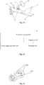
- Fig. 1 is a first flowchart of a control method according to an embodiment of the present disclosure.
- the control method in the embodiment is applied to a vehicle frame.
- the vehicle frame is configured to be connected with a power driving assembly, and the vehicle frame is provided with a manipulation assembly and a controller for controlling the power driving assembly.
- the control method includes the following operations.
- the controller detects a manipulation instruction from the manipulation assembly.
- the vehicle frame is of a frame structure in bridge connection to the front and rear of a vehicle, and is the foundation of the vehicle.
- the vehicle frame functions in supporting and connecting various assemblies of the vehicle so that the various assemblies are kept in a relatively correct position relationship, and bears various loads in and outside the vehicle.
- the controller is in wired or wireless connection with the manipulation assembly.
- the controller is in wired connection with the manipulation assembly; for example, the controller and the manipulation assembly are connected by wires, and the wires may be hidden in the vehicle frame.
- the controller is in wireless connection with the manipulation assembly; for example, the controller and the manipulation assembly are connected by means of Bluetooth communication.
- the manipulation assembly is any one or more assemblies capable of controlling the vehicle, such as a steering wheel, an accelerator, a brake, a gear lever, and a light control button.
- a user may manipulate the vehicle through the manipulation assembly. After obtaining an operation of the user, the manipulation assembly generates a corresponding manipulation instruction and sends the manipulation instruction to the controller for processing. After receiving the manipulation instruction, the controller controls a target object based on the manipulation instruction.
- the manipulation assembly is a steering wheel
- the sensor when the user turns the steering wheel which is provided with a sensor capable of detecting a turned angle, the sensor can detect the turned angle of the steering wheel, and a direction manipulation instruction can be generated based on the turned angle and sent to the controller.
- the controller After receiving the direction manipulation instruction, the controller determines a rotation angle of wheels, and controls the wheels to rotate, thereby realizing the control of the driving direction of the vehicle.
- the sensor capable of detecting the turned angle may also not be set on the steering wheel, the turning of the steering wheel is not used for controlling differential outputs of different wheels of the power driving assembly, but is only used for controlling the steering of the wheels except the power driving assembly, thereby changing the driving direction of the vehicle.
- the vehicle frame is in detachable connection with the power driving assembly.
- the vehicle frame is connected with the power driving assembly, then the vehicle frame and the power driving assembly are assembled into a vehicle, and the power driving assembly is in wired or wireless connection with the controller.
- the controller is in wired connection with the power driving assembly; for example, the controller and the power driving assembly are connected by the wires.
- the controller is in wireless connection with the power driving assembly; for example, the controller and the power driving assembly are connected by means of Bluetooth communication. In such a manner, communication channels are formed among the manipulation assembly, the controller and the power driving assembly. The action of the controller enables the user to use the manipulation assembly to manipulate the power driving assembly.
- connection mode between the vehicle frame and the power driving assembly is not limited.
- the power driving assembly may be buckled on the vehicle frame by means of a buckle.
- the power driving assembly may also be inserted on the vehicle frame by means of a slot.
- the power driving assembly may also be fixed on the vehicle frame by means of screws and rivets.
- the controller After the vehicle frame is connected with the power driving assembly and a communication connection is established between the controller and the power driving assembly, the controller detects a manipulation instruction from the manipulation assembly; for example, the controller detects an accelerator manipulation instruction from an accelerator, detects a brake instruction from a brake assembly, or detects a direction manipulation instruction from a direction manipulation assembly.
- the controller in response to detecting the manipulation instruction from the manipulation assembly and determining that the manipulation instruction corresponds to the power driving assembly, the controller generates, according to the manipulation instruction, a control instruction for controlling the power driving assembly, and sends the control instruction to the power driving assembly.
- the controller when detecting the manipulation instruction of the manipulation assembly, the controller first needs to determine the target object corresponding to the manipulation instruction, namely detecting which object the manipulation instruction needs to control. For example, when an instruction of switching on the headlight from the light control button is detected, it is determined that the object to be controlled is the headlight of the vehicle. For another example, when the direction manipulation instruction from the direction manipulation assembly is detected, it is determined that the object to be controlled is the power driving assembly. For another example, when the accelerator manipulation instruction from the accelerator is detected, it is determined that the object to be controlled is the power driving assembly.
- the control instruction for controlling the power driving assembly is generated according to the manipulation instruction, and the control instruction is sent to the power driving assembly, thereby performing corresponding control to the power driving assembly.
- the power driving assembly is used as a part of the vehicle.
- the user may conveniently use the manipulation assembly on the vehicle to control the power driving assembly through the controller, such as acceleration, deceleration or turning, so that the driving at a higher speed may be realized on the premise of the assurance of safety and reliability, and the user may use the vehicle to have racing entertainment.
- Fig. 3 is a second flowchart of the control method according to an embodiment of the present disclosure.
- the control method in the embodiment is applied to the vehicle frame.
- the vehicle frame is configured to be connected with the power driving assembly, and the vehicle frame is provided with a manipulation assembly and a controller for controlling the power driving assembly.
- the manipulation assembly includes the accelerator assembly.
- the control method includes the following operations.
- the controller detects an accelerator manipulation instruction from the accelerator assembly.
- the manipulation assembly includes accelerator assembly.
- the manipulation assembly may also include other assemblies, such as the brake assembly, the direction manipulation assembly, and/or a drive switch assembly.
- the embodiment is illustrated by taking the accelerator assembly in the manipulation assembly for example.
- the form of accelerator assembly is not limited.
- the accelerator assembly may be either a hand control accelerator or a foot control accelerator.
- the form of the accelerator may be a knob, then the user may control the accelerator by using the hand to turn the knob.
- the form of the accelerator may be a pedal, then the user may control the accelerator by applying different pressures to stamp on the pedal.
- the accelerator assembly is in wired or wireless connection with the controller.
- the controller is in wired connection with the accelerator assembly, for example, the controller and the accelerator assembly are connected by the wires, and the wires may be hidden in the vehicle frame.
- the controller is in wireless connection with the accelerator assembly; for example, the controller and the accelerator assembly are connected by means of Bluetooth communication.
- the controller After the vehicle frame is connected to the power driving assembly and a communication connection is established between the controller and the power driving assembly, the controller detects the accelerator manipulation instruction from the accelerator assembly.
- the accelerator manipulation instruction carries accelerator parameters.
- the accelerator parameters include, but are not limited to, a stamping force applied on an accelerator pedal, a stroke change of the accelerator pedal, and a rotation angle of the knob.
- the controller in response to detecting the accelerator manipulation instruction from the accelerator assembly, the controller generates, according to the accelerator manipulation instruction from the accelerator assembly, a first control instruction used for controlling power output of the power driving assembly.
- the first control instruction is used for instructing the power driving assembly to increase the power output.
- the controller in response to detecting the accelerator manipulation instruction from the accelerator assembly, the controller generates, according to the accelerator manipulation instruction from the accelerator assembly, the first control instruction used for controlling power output of the power driving assembly.
- the accelerator manipulation instruction corresponds to the accelerator assembly
- the first control instruction corresponds to the power driving assembly
- the controller aims to convert the accelerator manipulation instruction corresponding to the accelerator assembly into the first control instruction corresponding to the power driving assembly.
- A2 CxA1, where C is a constant, the greater the stamping force applied on the pedal, the higher the rotation acceleration of the power driving assembly.
- the rotation acceleration represents that the power driving assembly increases the power output.
- the technical solutions of the embodiments of the present disclosure may use the accelerator assembly to instruct, through the controller, the power driving assembly to increase the power output.
- Fig. 5 is a third flowchart of the control method according to an embodiment of the present disclosure.
- the control method in the embodiment is applied to the vehicle frame.
- the vehicle frame is configured to be connected with the power driving assembly, and the vehicle frame is provided with a manipulation assembly and a controller for controlling the power driving assembly.
- the manipulation assembly includes a brake assembly.
- the control method includes the following operations.
- the controller detects a brake instruction from the brake assembly.
- the manipulation assembly includes the brake assembly.
- the manipulation assembly may also include other assemblies, such as the accelerator assembly, the direction manipulation assembly, and the drive switch assembly.
- the embodiment is illustrated by taking the brake assembly in the manipulation assembly for example.
- the form of brake assembly is not limited.
- the brake assembly may be either a hand control brake or a foot control brake.
- the brake assembly is in wired or wireless connection with the controller.
- the controller is in wired connection with the accelerator assembly, for example, the controller and the accelerator assembly are connected by the wires, and the wires may be hidden in the vehicle frame.
- the controller is in wireless connection with the brake assembly; for example, the controller and the brake assembly are connected by means of Bluetooth communication.
- the controller After the vehicle frame is connected to the power driving assembly and a communication connection is established between the controller and the power driving assembly, the controller detects the brake instruction from the brake assembly.
- the brake instruction carries brake force parameters.
- the brake force parameters include, but are not limited to, the following parameters: a stamping force applied on a brake pedal and a stroke change of the brake pedal.
- the controller in response to detecting the brake instruction from the brake assembly, the controller generates, according to the brake instruction from the brake assembly, a second control instruction used for controlling power output of the power driving assembly.
- the second control instruction is used for instructing the power driving assembly to reduce the power output.
- the controller in response to detecting the brake instruction from the brake assembly, the controller generates, according to the brake instruction from the brake assembly, the second control instruction used for controlling power output of the power driving assembly.
- the brake instruction corresponds to the brake assembly
- the second control instruction corresponds to the power driving assembly
- the controller aims to convert the brake instruction corresponding to the brake assembly into the second control instruction corresponding to the power driving assembly.
- the rotation deceleration represents that the power driving assembly reduces the power output.
- the technical solutions of the embodiments of the present disclosure may use the brake assembly to instruct, through the controller, the power driving assembly to reduce the power output.
- Fig. 6 is a fourth flowchart of the control method according to an embodiment of the present disclosure.
- the control method in the embodiment is applied to the vehicle frame.
- the vehicle frame is configured to be connected with the power driving assembly, and the vehicle frame is provided with a manipulation assembly and a controller for controlling the power driving assembly.
- the manipulation assembly includes a direction manipulation assembly.
- the control method includes the following operations.
- the controller detects a direction manipulation instruction from the direction manipulation assembly.
- the manipulation assembly includes the direction manipulation assembly.
- the manipulation assembly may also include other assemblies, such as the accelerator assembly, the brake assembly, and the drive switch assembly.
- the embodiment is illustrated by taking the direction manipulation assembly in the manipulation assembly for example.
- the direction manipulation assembly may be in the form of the steering wheel, and the user may control the direction manipulation assembly by turning the steering wheel.
- the direction manipulation assembly is in wired or wireless connection with the controller.
- the controller is in wired connection with the direction manipulation assembly, for example, the controller and the direction manipulation assembly are connected by the wires, and the wires may be hidden in the vehicle frame.
- the controller is in wireless connection with the direction manipulation assembly; for example, the controller and the direction manipulation assembly are connected by means of Bluetooth communication.
- the controller After the vehicle frame is connected to the power driving assembly and a communication connection is established between the controller and the power driving assembly, the controller detects the direction manipulation instruction from the direction manipulation assembly.
- the direction manipulation instruction carries the turned angle of the steering wheel
- the direction manipulation assembly is provided with a sensor capable of detecting the turned angle of the steering wheel.
- the controller in response to detecting the direction manipulation instruction from the direction manipulation assembly, the controller generates, according to the direction manipulation instruction from the direction manipulation assembly, a third control instruction used for controlling power output of the power driving assembly.
- the third control instruction is used for instructing different drive units in the power driving assembly to provide differential power outputs.
- the controller in response to detecting the direction manipulation instruction from the direction manipulation assembly, the controller generates, according to the direction manipulation instruction from the direction manipulation assembly, the third control instruction used for controlling power output of the power driving assembly.
- the direction manipulation instruction corresponds to the direction manipulation assembly
- the third control instruction corresponds to the power driving assembly
- the controller aims to convert the direction manipulation instruction corresponding to the direction manipulation assembly into the third control instruction corresponding to the power driving assembly.
- the turned angle carried in the direction manipulation instruction corresponding to the direction manipulation assembly is G1
- the drive parameter carried in the third control instruction is G2 (g1, g2)
- g1 represents the rotation speed of the left drive unit in the power driving assembly
- g2 represents the rotation speed of the right drive unit in the power driving assembly
- each drive unit in the power driving assembly is reasonably deduced according to the turned angle in the direction manipulation instruction, and then each of the drive units is controlled to rotate differentially (namely the power outputs) according to the corresponding rotation speed.
- Fig. 7 is a fifth flowchart of the control method according to an embodiment of the present disclosure.
- the control method in the embodiment is applied to the vehicle frame.
- the vehicle frame is configured to be connected with the power driving assembly, and the vehicle frame is provided with a manipulation assembly and a controller for controlling the power driving assembly.
- the power driving assembly and the vehicle frame are connected in the following ways:
- the manipulation assembly includes the drive switch assembly.
- the control method includes the following operations.
- the controller detects the direction manipulation instruction from the drive switch assembly.
- the manipulation assembly includes the drive switch assembly.
- the manipulation assembly may also include other assemblies, such as the accelerator assembly, the brake assembly, and the direction manipulation assembly.
- the embodiment is illustrated by taking the drive switch assembly in the manipulation assembly for example.
- the drive switch assembly may be in the form of the button, and the user may control the drive switch assembly through the button.
- the drive switch assembly is in wired or wireless connection with the controller.
- the controller is in wired connection with the drive switch assembly, for example, the controller and the drive switch assembly are connected by the wires, and the wires may be hidden in the vehicle frame.
- the controller is in wireless connection with the drive switch assembly; for example, the controller and the drive switch assembly are connected by means of Bluetooth communication.
- the controller After the vehicle frame is connected to the power driving assembly and a communication connection is established between the controller and the power driving assembly, the controller detects the drive switch instruction from the drive switch assembly.
- the drive switch instruction carries the drive modes to be switched.
- the drive modes at least include: a first drive mode, a second drive mode and a third drive mode.
- the first drive mode the power driving assembly only connected to the front end of the vehicle frame provides the power output.
- the power driving assembly In the second drive mode, the power driving assembly only connected to the rear end of the vehicle frame provides the power output.
- both the power driving assembly connected to the front end of the vehicle frame and the power driving assembly connected to the rear end of the vehicle frame provide the power output.
- the controller in response to detecting the drive switch instruction from the drive switch assembly, the controller generates, according to the drive switch instruction from the drive switch assembly, a fourth control instruction used for controlling the drive modes of the power driving assembly.
- the fourth control instruction is used for instructing the power driving assembly to switch the drive modes.
- the controller in response to detecting the drive switch instruction from the drive switch assembly, the controller generates, according to the drive switch instruction from the drive switch assembly, the fourth control instruction used for controlling the drive modes of the power driving assembly.
- the fourth control instruction controls the power driving assembly on the front end of the vehicle frame to be in a driving state.
- the power driving assembly is in the driving state means the power driving assembly may provide the power output.
- the fourth control instruction controls the power driving assembly on the rear end of the vehicle frame to be in the driving state.
- the fourth control instruction controls the power driving assemblies on the front end and the rear end of the vehicle frame to be in the driving state at the same time.
- Fig. 8 is a sixth flowchart of the control method according to an embodiment of the present disclosure.
- the control method in the embodiment is applied to the power driving assembly.
- the power driving assembly is configured to be connected with the vehicle frame.
- the vehicle frame is provided with the manipulation assembly.
- the controller for controlling the power driving assembly is set on the vehicle frame or on the power driving assembly. As illustrated in Fig. 8 , the control method includes the following operations.
- the power driving assembly After the power driving assembly is connected to the vehicle frame, the power driving assembly enters a first operating mode.
- the vehicle frame is of a frame structure in bridge connection to the front and rear of a vehicle, and is the foundation of the vehicle.
- the vehicle frame functions in supporting and connecting various assemblies of the vehicle so that the various assemblies are kept in a relatively correct position relationship, and bears various loads in and outside the vehicle.
- the controller used for controlling the power driving assembly and the manipulation assembly on the vehicle frame.
- the controller is in wired or wireless connection with the manipulation assembly.
- the controller is in wired connection with the manipulation assembly; for example, the controller and the manipulation assembly are connected by wires, and the wires may be hidden in the vehicle frame.
- the controller is in wireless connection with the manipulation assembly; for example, the controller and the manipulation assembly are connected by means of Bluetooth communication.
- the manipulation assembly on the vehicle frame, and there is the controller used for controlling the power driving assembly on the power driving assembly.
- the controller is in wired or wireless connection with the manipulation assembly.
- the controller is in wired connection with the manipulation assembly; for example, the controller and the manipulation assembly are connected by the wires.
- the controller is in wireless connection with the manipulation assembly; for example, the controller and the manipulation assembly are connected by means of Bluetooth communication.
- the manipulation assembly is any one or more assemblies capable of controlling the vehicle, such as a steering wheel, an accelerator, a brake, a gear lever, and a light control button.
- a user may manipulate the vehicle through the manipulation assembly. After obtaining an operation of the user, the manipulation assembly generates a corresponding manipulation instruction and sends the manipulation instruction to the controller for processing. After receiving the manipulation instruction, the controller controls a target object based on the manipulation instruction.
- the manipulation assembly is a steering wheel
- the sensor when the user turns the steering wheel which is provided with a sensor capable of detecting a turned angle, the sensor can detect the turned angle of the steering wheel, and a direction manipulation instruction can be generated based on the turned angle and sent to the controller.
- the controller After receiving the direction manipulation instruction, the controller determines a rotation angle of wheels, and controls the wheels to rotate, thereby realizing the control of the driving direction of the vehicle.
- the sensor capable of detecting the turned angle may also not be set on the steering wheel, the turning of the steering wheel is not used for controlling differential outputs of different wheels of the power driving assembly, but is only used for controlling the steering of the wheels except the power driving assembly, thereby changing the driving direction of the vehicle.
- the vehicle frame is in detachable connection with the power driving assembly.
- the vehicle frame is connected with the power driving assembly, then the vehicle frame and the power driving assembly are assembled into a vehicle.
- connection mode between the vehicle frame and the power driving assembly is not limited.
- the power driving assembly may be buckled on the vehicle frame by means of the buckle.
- the power driving assembly may also be inserted on the vehicle frame by means of the slot.
- the power driving assembly may also be fixed on the vehicle frame by means of the screws and rivets.
- the power driving assembly has two operating states. After the power driving assembly is connected to the vehicle frame, the power driving assembly enters the first operating state. After the power driving assembly is disconnected from the vehicle frame, the power driving assembly enters the second operating mode.
- the power driving assembly in the first operating mode receives a control instruction from the controller.
- the controller is set on the vehicle frame, and the power driving assembly is in wired or wireless connection with the controller.
- the controller is in wired connection with the power driving assembly; for example, the controller and the power driving assembly are connected by the wires.
- the controller is in wireless connection with the power driving assembly; for example, the controller and the power driving assembly are connected by means of Bluetooth communication.
- communication channels are formed among the manipulation assembly, the controller and the power driving assembly. The action of the controller enables the user to use the manipulation assembly to manipulate the power driving assembly.
- the controller is set on the power driving assembly, and the controller on the power driving assembly is in wired or wireless connection with the manipulation assembly on the vehicle frame.
- the communication channel is formed between the manipulation assembly and the controller in the power driving assembly. The action of the controller enables the user to use the manipulation assembly to manipulate the power driving assembly.
- the power driving assembly controls power output of the power driving assembly according to the received control instruction.
- the manipulation assemblies include the accelerator assembly, the brake assembly, the direction manipulation assembly, the drive switch assembly, and so on.
- the implementation of each manipulation assembly is illustrated below.
- the manipulation assemblies include the accelerator assembly.
- the power driving assembly controls power output of the power driving assembly according to the received control instruction includes that:
- the form of accelerator assembly is not limited.
- the accelerator assembly may be either the hand control accelerator or the foot control accelerator.
- the form of the accelerator may be a knob, then the user may control the accelerator by using the hand to turn the knob.
- the form of the accelerator may be a pedal, then the user may control the accelerator by applying different pressures to stamp on the pedal.
- the accelerator assembly is in wired or wireless connection with the controller.
- the controller is in wired connection with the accelerator assembly, for example, the controller and the accelerator assembly are connected by the wires, and the wires may be hidden in the vehicle frame.
- the controller is in wireless connection with the accelerator assembly; for example, the controller and the accelerator assembly are connected by means of Bluetooth communication.
- the first control instruction carriers the drive parameters.
- the drive parameters include, but are not limited to, the following parameters: the rotation speed of the power driving assembly and the rotation acceleration of the power driving assembly.
- the power increase strategy corresponding to the first control instruction is that: the rotation speed and the rotation acceleration of each drive unit are controlled according to the drive parameters in the first control instruction.
- the manipulation assemblies include the accelerator assembly.
- that the power driving assembly controls power output of the power driving assembly according to the received control instruction includes that:
- the form of brake assembly is not limited.
- the brake assembly may be either the hand control brake or the foot control brake.
- the brake assembly is in wired or wireless connection with the controller.
- the controller is in wired connection with the brake assembly, for example, the controller and the brake assembly are connected by the wires, and the wires may be hidden in the vehicle frame.
- the controller is in wireless connection with the brake assembly; for example, the controller and the brake assembly are connected by means of Bluetooth communication.
- the second control instruction carriers the drive parameters.
- the drive parameters include, but are not limited to, the following parameters: the rotation speed of the power driving assembly and the rotation deceleration of the power driving assembly.
- the power reduction strategy corresponding to the second control instruction is that: the rotation speed and the rotation deceleration of each drive unit are controlled according to the drive parameters in the second control instruction.
- the manipulation assemblies include the direction manipulation assembly.
- that the power driving assembly controls power output of the power driving assembly according to the received control instruction includes that:
- the direction manipulation assembly may be in the form of the steering wheel, and the user may control the direction manipulation assembly by turning the steering wheel.
- the direction manipulation assembly is in wired or wireless connection with the controller.
- the controller is in wired connection with the direction manipulation assembly, for example, the controller and the direction manipulation assembly are connected by the wires, and the wires may be hidden in the vehicle frame.
- the controller is in wireless connection with the direction manipulation assembly; for example, the controller and the direction manipulation assembly are connected by means of Bluetooth communication.
- the drive parameter carried in the third control instruction is G2 (g1, g2), where g1 represents the rotation speed of the left drive unit in the power driving assembly, and g2 represents the rotation speed of the right drive unit in the power driving assembly, when g1 is greater than g2, the whole vehicle turns right; when g1 is less than g2, the whole vehicle turns left; and when g1 is equal to g2, the vehicle goes straight ahead.
- G2 (g1, g2)
- g1 represents the rotation speed of the left drive unit in the power driving assembly
- g2 represents the rotation speed of the right drive unit in the power driving assembly
- the power driving assembly and the vehicle frame are connected in the following ways:
- the power driving assembly receives the fourth control instruction from the controller.
- the fourth control instruction is used for instructing the power driving assembly to switch the drive modes.
- the drive modes at least include: the first drive mode, the second drive mode and the third drive mode. In the first drive mode, the power driving assembly only connected to the front end of the vehicle frame provides the power output. In the second drive mode, the power driving assembly only connected to the rear end of the vehicle frame provides the power output. In the third drive mode, both the power driving assembly connected to the front end of the vehicle frame and the power driving assembly connected to the rear end of the vehicle frame provide the power output.
- Fig. 9 is a seventh flowchart of the control method according to an embodiment of the present disclosure.
- the control method in the embodiment is applied to the power driving assembly.
- the power driving assembly is configured to be connected with the vehicle frame.
- the vehicle frame is provided with the manipulation assembly.
- the controller for controlling the power driving assembly is set on the vehicle frame or on the power driving assembly. As illustrated in Fig. 9 , the control method includes the following operations.
- the power driving assembly After the power driving assembly is connected to the vehicle frame, the power driving assembly enters the first operating mode.
- the vehicle frame is of a frame structure in bridge connection to the front and rear of a vehicle, and is the foundation of the vehicle.
- the vehicle frame functions in supporting and connecting various assemblies of the vehicle so that the various assemblies are kept in a relatively correct position relationship, and bears various loads in and outside the vehicle.
- the controller used for controlling the power driving assembly and the manipulation assembly on the vehicle frame.
- the controller is in wired or wireless connection with the manipulation assembly.
- the controller is in wired connection with the manipulation assembly; for example, the controller and the manipulation assembly are connected by wires, and the wires may be hidden in the vehicle frame.
- the controller is in wireless connection with the manipulation assembly; for example, the controller and the manipulation assembly are connected by means of Bluetooth communication.
- the manipulation assembly on the vehicle frame, and there is the controller used for controlling the power driving assembly on the power driving assembly.
- the controller is in wired or wireless connection with the manipulation assembly.
- the controller is in wired connection with the manipulation assembly; for example, the controller and the manipulation assembly are connected by the wires.
- the controller is in wireless connection with the manipulation assembly; for example, the controller and the manipulation assembly are connected by means of Bluetooth communication.
- the manipulation assembly is any one or more assemblies capable of controlling the vehicle, such as a steering wheel, an accelerator, a brake, a gear lever, and a light control button.
- a user may manipulate the vehicle through the manipulation assembly. After obtaining an operation of the user, the manipulation assembly generates a corresponding manipulation instruction and sends the manipulation instruction to the controller for processing. After receiving the manipulation instruction, the controller controls a target object based on the manipulation instruction.
- the manipulation assembly is a steering wheel
- the sensor when the user turns the steering wheel which is provided with a sensor capable of detecting a turned angle, the sensor can detect the turned angle of the steering wheel, and a direction manipulation instruction can be generated based on the turned angle and sent to the controller.
- the controller After receiving the direction manipulation instruction, the controller determines a rotation angle of wheels, and controls the wheels to rotate, thereby realizing the control of the driving direction of the vehicle.
- the sensor capable of detecting the turned angle may also not be set on the steering wheel, the turning of the steering wheel is not used for controlling differential outputs of different wheels of the power driving assembly, but is only used for controlling the steering of the wheels except the power driving assembly, thereby changing the driving direction of the vehicle.
- the vehicle frame is in detachable connection with the power driving assembly.
- the vehicle frame is connected with the power driving assembly, then the vehicle frame and the power driving assembly are assembled into a vehicle.
- connection mode between the vehicle frame and the power driving assembly is not limited.
- the power driving assembly may be buckled on the vehicle frame by means of the buckle.
- the power driving assembly may also be inserted on the vehicle frame by means of the slot.
- the power driving assembly may also be fixed on the vehicle frame by means of the screws and rivets.
- the power driving assembly has two operating states. After the power driving assembly is connected to the vehicle frame, the power driving assembly enters the first operating state. After the power driving assembly is disconnected from the vehicle frame, the power driving assembly enters the second operating mode.
- the power driving assembly in the first operating mode receives a control instruction from the controller.
- the controller is set on the vehicle frame, and the power driving assembly is in wired or wireless connection with the controller.
- the controller is in wired connection with the power driving assembly; for example, the controller and the power driving assembly are connected by the wires.
- the controller is in wireless connection with the power driving assembly; for example, the controller and the power driving assembly are connected by means of Bluetooth communication.
- communication channels are formed among the manipulation assembly, the controller and the power driving assembly. The action of the controller enables the user to use the manipulation assembly to manipulate the power driving assembly.
- the controller is set on the power driving assembly, and the controller on the power driving assembly is in wired or wireless connection with the manipulation assembly on the vehicle frame.
- the communication channel is formed between the manipulation assembly and the controller in the power driving assembly. The action of the controller enables the user to use the manipulation assembly to manipulate the power driving assembly.
- the power driving assembly controls power output of the power driving assembly according to the received control instruction.
- the manipulation assemblies include the accelerator assembly, the brake assembly, the direction manipulation assembly, the drive switch assembly, and so on.
- the implementation of each manipulation assembly is illustrated below.
- the manipulation assemblies include the accelerator assembly.
- the power driving assembly controls power output of the power driving assembly according to the received control instruction includes that:
- the form of accelerator assembly is not limited.
- the accelerator assembly may be either the hand control accelerator or the foot control accelerator.
- the form of the accelerator may be a knob, then the user may control the accelerator by using the hand to turn the knob.
- the form of the accelerator may be a pedal, then the user may control the accelerator by applying different pressures to stamp on the pedal.
- the accelerator assembly is in wired or wireless connection with the controller.
- the controller is in wired connection with the accelerator assembly, for example, the controller and the accelerator assembly are connected by the wires, and the wires may be hidden in the vehicle frame.
- the controller is in wireless connection with the accelerator assembly; for example, the controller and the accelerator assembly are connected by means of Bluetooth communication.
- the first control instruction carriers the drive parameters.
- the drive parameters include, but are not limited to, the following parameters: the rotation speed of the power driving assembly and the rotation acceleration of the power driving assembly.
- the power increase strategy corresponding to the first control instruction is that: the rotation speed and the rotation acceleration of each drive unit are controlled according to the drive parameters in the first control instruction.
- the manipulation assemblies include the accelerator assembly.
- that the power driving assembly controls power output of the power driving assembly according to the received control instruction includes that:
- the form of brake assembly is not limited.
- the brake assembly may be either the hand control brake or the foot control brake.
- the brake assembly is in wired or wireless connection with the controller.
- the controller is in wired connection with the brake assembly, for example, the controller and the brake assembly are connected by the wires, and the wires may be hidden in the vehicle frame.
- the controller is in wireless connection with the brake assembly; for example, the controller and the brake assembly are connected by means of Bluetooth communication.
- the second control instruction carriers the drive parameters.
- the drive parameters include, but are not limited to, the following parameters: the rotation speed of the power driving assembly and the rotation deceleration of the power driving assembly.
- the power reduction strategy corresponding to the second control instruction is that: the rotation speed and the rotation deceleration of each drive unit are controlled according to the drive parameters in the second control instruction.
- the manipulation assemblies include the direction manipulation assembly.
- that the power driving assembly controls power output of the power driving assembly according to the received control instruction includes that:
- the direction manipulation assembly may be in the form of the steering wheel, and the user may control the direction manipulation assembly by turning the steering wheel.
- the direction manipulation assembly is in wired or wireless connection with the controller.
- the controller is in wired connection with the direction manipulation assembly, for example, the controller and the direction manipulation assembly are connected by the wires, and the wires may be hidden in the vehicle frame.
- the controller is in wireless connection with the direction manipulation assembly; for example, the controller and the direction manipulation assembly are connected by means of Bluetooth communication.
- the drive parameter carried in the third control instruction is G2 (g1, g2), where g1 represents the rotation speed of the left drive unit in the power driving assembly, and g2 represents the rotation speed of the right drive unit in the power driving assembly, when g1 is greater than g2, the whole vehicle turns right; when g1 is less than g2, the whole vehicle turns left; and when g1 is equal to g2, the vehicle goes straight ahead.
- G2 (g1, g2)
- g1 represents the rotation speed of the left drive unit in the power driving assembly
- g2 represents the rotation speed of the right drive unit in the power driving assembly
- the power driving assembly and the vehicle frame are connected in the following ways:
- the power driving assembly receives the fourth control instruction from the controller.
- the fourth control instruction is used for instructing the power driving assembly to switch the drive modes.
- the drive modes at least include: the first drive mode, the second drive mode and the third drive mode. In the first drive mode, the power driving assembly only connected to the front end of the vehicle frame provides the power output. In the second drive mode, the power driving assembly only connected to the rear end of the vehicle frame provides the power output. In the third drive mode, both the power driving assembly connected to the front end of the vehicle frame and the power driving assembly connected to the rear end of the vehicle frame provide the power output.
- the power driving assembly After the power driving assembly is disconnected from the vehicle frame, the power driving assembly enters the second operating mode.
- the second operating mode is different from the first operating mode. In the second operating mode, the power driving assembly does not provide power output for the vehicle frame.
- the power driving assembly has a self-balancing system.
- the self-balancing system of the power driving assembly does not operate, and the power driving assembly provides power output for the vehicle frame.
- the self-balancing system of the power driving assembly operates.
- the self-balancing system may detect the gravity center of human body, and control the power output of each drive unit in the power driving assembly according to the gravity center of human body, thereby realizing the following operations of the power driving assembly: going forward, going backward, turning and stopping. For example, when the gravity center of human body leans to the left, the self-balancing system controls the power driving assembly to turn left; when the gravity center of human body leans to the right, the self-balancing system controls the power driving assembly to turn right; when the gravity center of human body leans forward, the self-balancing system controls the power driving assembly to go forward; and when the gravity center of human body leans backward, the self-balancing system controls the power driving assembly to go backward or decelerate or stop.
- Fig. 10 is a first structure diagram of the vehicle frame according to an embodiment of the present disclosure.
- the vehicle frame 10 is configured to be connected with the power driving assembly, and the vehicle frame 10 is provided with the controller 101 for controlling the power driving assembly, and the manipulation assembly.
- the controller 101 is configured to detect the manipulation instruction from the manipulation assembly, in response to detecting the manipulation instruction from the manipulation assembly and determining that the manipulation instruction corresponds to the power driving assembly, generate, according to the manipulation instruction, the control instruction for controlling the power driving assembly, and send the control instruction to the power driving assembly.
- the manipulation assembly includes the accelerator assembly 102.
- the accelerator assembly 102 is connected with the controller 101.
- the controller 101 is specifically configured to generate, according to the accelerator manipulation instruction from the accelerator assembly 102, the first control instruction used for controlling power output of the power driving assembly.
- the first control instruction is used for instructing the power driving assembly to increase the power output.
- the manipulation assembly includes the brake assembly 103.
- the brake assembly 103 is connected with the controller 101.
- the controller 101 is specifically configured to generate, according to the brake instruction from the brake assembly 103, the second control instruction used for controlling power output of the power driving assembly.
- the second control instruction is used for instructing the power driving assembly to reduce the power output.
- the manipulation assembly includes the direction manipulation assembly 104.
- the direction manipulation assembly 104 is connected with the controller 101.
- the controller 101 is specifically configured to generate, according to the direction manipulation instruction from the direction manipulation assembly 104, the third control instruction used for controlling power output of the power driving assembly.
- the third control instruction is used for instructing the different drive units in the power driving assembly to provide differential power outputs.
- the power driving assembly and the vehicle frame 10 are connected in the following ways:
- the manipulation assembly includes the drive switch assembly 105.
- the drive switch assembly 105 is connected with the controller 101.
- the controller 101 is specifically configured to generate, according to the drive switch instruction from the drive switch assembly 105, the fourth control instruction used for controlling the drive modes of the power driving assembly.
- the fourth control instruction is used for instructing the power driving assembly to switch the drive modes.
- the drive modes at least include: the first drive mode, the second drive mode and the third drive mode.
- the first drive mode the power driving assembly only connected to the front end of the vehicle frame 10 provides the power output.
- the second drive mode the power driving assembly only connected to the rear end of the vehicle frame 10 provides the power output.
- the third drive mode both the power driving assembly connected to the front end of the vehicle frame and the power driving assembly connected to the rear end of the vehicle frame 10 provide the power output.
- the embodiments of the present disclosure also provide a vehicle frame with a specific shape. It is to be noted that the vehicle frame in the embodiments of the present disclosure is not limited to the shape illustrated in Fig. 11 , and all the vehicle frames in any shape should fall within the protection scope of the present disclosure as long as they can implement the solutions of the embodiments of the present disclosure. As illustrated in Fig. 11 , the vehicle frame 10 includes: the controller 101, the accelerator assembly 102, the brake assembly 103, the direction manipulation assembly 104, a front wheel assembly 105, and a chair assembly 106. Of course, the vehicle frame may also be provided with more assemblies, such as a display screen, a sound box, and a lamp.
- Fig. 12 is a first structure diagram of the power driving assembly according to an embodiment of the present disclosure.
- the power driving assembly 20 is configured to be connected with the vehicle frame, the vehicle frame is provided with the manipulation assembly, the controller 200 for controlling the power driving assembly is set on the vehicle frame or on the power driving assembly.
- the power driving assembly 20 includes: a processor 201 and a power output assembly 202. After the power driving assembly 20 is connected to the vehicle frame, the power driving assembly 20 enters the first operating mode.
- the processor 201 is configured to receive, after establishing communication connection with the controller 200, the control instruction from the controller 200, and control the power output of the power output assembly 202 according to the received control instruction.
- the power driving assembly 20 after the power driving assembly 20 is disconnected from the vehicle frame, the power driving assembly 20 enters the second operating mode.
- the second operating mode is different from the first operating mode.
- the power output assembly 202 does not provide power output for the vehicle frame.
- the power driving assembly 20 has the self-balancing system. In the first operating mode, the self-balancing system of the power driving assembly 20 does not operate, and the power output assembly 202 provides the power output for the vehicle frame. In the second operating mode, the self-balancing system of the power driving assembly 20 operates.
- the manipulation assembly includes the accelerator assembly.
- the processor 201 is specifically configured to receive the first control instruction from the controller 200.
- the first control instruction is used for instructing the power output assembly 202 to increase the power output, determine, according to the first control instruction, the power increase strategy of the power output assembly 202, and control the power output assembly 202 to increase the power output based on the power increase strategy.
- the manipulation assembly includes the brake assembly.
- the processor 201 is specifically configured to receive the second control instruction from the controller 200.
- the second control instruction is used for instructing the power output assembly 202 to reduce the power output, determine, according to the second control instruction, the power reduction strategy of the power output assembly 202, and control the power output assembly 202 to reduce the power output based on the power reduction strategy.
- the manipulation assembly includes the direction manipulation assembly.
- the processor 201 is specifically configured to receive the third control instruction from the controller 200.
- the third control instruction is used for instructing different drive units in the power output assembly 202 to provide differential power outputs, determine, according to the third control instruction, the differential power output strategy of the power output assembly 202, and control the different drive units in the power output assembly 202 to provide the differential power outputs based on the differential power output strategy.
- the power driving assembly 20 is only connected to a front end of the vehicle frame, and serves as the front driving power assembly of the vehicle frame; or, the power driving assembly 20 is only connected to a rear end of the vehicle frame, and serves as the rear driving power assembly of the vehicle frame; or, the power driving assembly 20 connected to the front end of the vehicle frame serves as the front driving power assembly of the vehicle frame, and the power driving assembly 20 connected to the rear end of the vehicle frame serves as the rear driving power assembly of the vehicle frame.
- the manipulation assembly includes the drive switch assembly.
- the processor 201 is specifically configured to receive the fourth control instruction from the controller 200.
- the fourth control instruction is used for instructing the power driving assembly 20 to switch the drive modes.
- the drive modes at least include: the first drive mode, the second drive mode and the third drive mode.
- the first drive mode the power driving assembly 20 only connected to the front end of the vehicle frame provides the power output.
- the second drive mode the power driving assembly 20 only connected to the rear end of the vehicle frame provides the power output.
- both the power driving assemblies 20 connected to the front end and the rear end of the vehicle frame provide the power output.
- the embodiments of the present disclosure also provide a power driving assembly with a specific shape. It is to be noted that the power driving assembly in the embodiments of the present disclosure is not limited to the shape illustrated in Fig. 13 , and all the power driving assemblies in any shape should fall within the protection scope of the present disclosure as long as they can implement the solutions of the embodiments of the present disclosure. As illustrated in Fig. 13 , the power driving assembly 20 includes: the processor (not illustrated), the power output assembly 202, the pedal 203, the self-balancing system (not illustrated), and a power supply (not illustrated). Of course, the power driving assembly may be more assemblies, such as an indicator light and a communication module.
- the embodiments of the present disclosure also provide a vehicle.
- the vehicle includes any above vehicle frame and power driving assembly.
- Fig. 14 and Fig. 15 are structure diagrams of a vehicle with a specific shape. It is to be noted that the vehicle in the embodiments of the present disclosure is not limited to the shapes illustrated in Fig. 14 and Fig. 15 , and all the vehicles in any shape should fall within the protection scope of the present disclosure as long as they can implement the solutions of the embodiments of the present disclosure.
- the vehicle includes: the vehicle frame 10 and the power driving assembly 20.
- the power driving assembly 20 is in detachable connection with the vehicle frame 10.
- the vehicle frame 10 includes: the controller 101, the accelerator assembly 102, the brake assembly 103, the direction manipulation assembly 104, the front wheel assembly 105, and the chair assembly 106.
- the power driving assembly 20 includes: the processor (not illustrated), the power output assembly 202, the pedal 203, the self-balancing system (not illustrated), and the power supply (not illustrated).
- Fig. 16 is a lateral view of the vehicle. At this point, the self-balancing system of the power driving assembly 20 is turned off, and the power driving assembly 20 provides the power output for the vehicle under the control of the controller 101.
- the power driving assembly 20 When the power driving assembly 20 is disconnected from the vehicle frame 10, the power driving assembly may be used as the self-balancing scooter; at this point, the self-balancing system of the power driving assembly 20 is turned on, and the user may use the power driving assembly 20 as a transportation tool.
Landscapes
- Engineering & Computer Science (AREA)
- Mechanical Engineering (AREA)
- Transportation (AREA)
- Chemical & Material Sciences (AREA)
- Combustion & Propulsion (AREA)
- Power Engineering (AREA)
- Electric Propulsion And Braking For Vehicles (AREA)
- Steering Control In Accordance With Driving Conditions (AREA)
- Control Of Driving Devices And Active Controlling Of Vehicle (AREA)
- Automatic Cycles, And Cycles In General (AREA)
Applications Claiming Priority (2)
| Application Number | Priority Date | Filing Date | Title |
|---|---|---|---|
| CN201710321683.4A CN107161260B (zh) | 2017-05-09 | 2017-05-09 | 一种控制方法、车架、动力驱动组件及车辆 |
| PCT/CN2018/082368 WO2018205785A1 (zh) | 2017-05-09 | 2018-04-09 | 一种控制方法、车架、动力驱动组件及车辆 |
Publications (3)
| Publication Number | Publication Date |
|---|---|
| EP3623271A1 true EP3623271A1 (de) | 2020-03-18 |
| EP3623271A4 EP3623271A4 (de) | 2021-01-20 |
| EP3623271B1 EP3623271B1 (de) | 2023-08-30 |
Family
ID=59812544
Family Applications (1)
| Application Number | Title | Priority Date | Filing Date |
|---|---|---|---|
| EP18799027.0A Active EP3623271B1 (de) | 2017-05-09 | 2018-04-09 | Steuerungsverfahren, fahrzeugrahmen, antriebsanordnung und fahrzeug |
Country Status (7)
| Country | Link |
|---|---|
| US (1) | US11440402B2 (de) |
| EP (1) | EP3623271B1 (de) |
| JP (1) | JP6997806B2 (de) |
| KR (1) | KR20200005634A (de) |
| CN (1) | CN107161260B (de) |
| MX (1) | MX2019013444A (de) |
| WO (1) | WO2018205785A1 (de) |
Families Citing this family (7)
| Publication number | Priority date | Publication date | Assignee | Title |
|---|---|---|---|---|
| CN107161260B (zh) | 2017-05-09 | 2021-10-26 | 纳恩博(北京)科技有限公司 | 一种控制方法、车架、动力驱动组件及车辆 |
| CN107902031B (zh) * | 2017-10-27 | 2021-02-12 | 纳恩博(北京)科技有限公司 | 一种电子刹车方法、车架、动力驱动组件及车辆 |
| CN110239651B (zh) * | 2019-07-05 | 2024-05-07 | 岭南师范学院 | 一种模块化组装式代步车 |
| CN110588864A (zh) * | 2019-08-27 | 2019-12-20 | 永康骑客智能科技股份有限公司 | 车辆组件、车架单元以及车辆组件控制方法 |
| CN113044150A (zh) * | 2019-12-10 | 2021-06-29 | 纳恩博(常州)科技有限公司 | 一种速度控制方法及装置、车辆、计算机可读存储介质 |
| JP7068359B2 (ja) * | 2020-01-31 | 2022-05-16 | 本田技研工業株式会社 | 移動体および電動車両 |
| CN114495469A (zh) * | 2020-10-25 | 2022-05-13 | 纳恩博(北京)科技有限公司 | 车辆的控制方法、装置、电子设备及存储介质 |
Family Cites Families (47)
| Publication number | Priority date | Publication date | Assignee | Title |
|---|---|---|---|---|
| CA1230292A (en) | 1984-10-22 | 1987-12-15 | Ontario Drive And Gear Limited | Vehicle drive and suspension system |
| DE3738915B4 (de) * | 1987-11-17 | 2006-03-09 | Robert Bosch Gmbh | Universalsteuergerät für Regeleinrichtungen |
| US5351774A (en) * | 1992-06-02 | 1994-10-04 | Quickie Designs Inc. | Powered wheelchair with a detachable power drive assembly |
| DE19618161C1 (de) * | 1996-05-07 | 1997-06-05 | Daimler Benz Ag | Selbstüberprüfung einer Funktionsgruppe in einem Kraftfahrzeug |
| AU3542797A (en) | 1996-07-09 | 1998-02-02 | Friedrich Grimm | Single track two-wheeled vehicle |
| DE19720285A1 (de) * | 1997-05-15 | 1998-11-19 | Bosch Gmbh Robert | Verfahren zur manipulationssicheren Konfigurierung eines Kfz-Steuergerätes sowie Steuergerät |
| DE10000337B4 (de) * | 2000-01-07 | 2015-03-19 | Volkswagen Ag | Verwaltungsvorrichtung eines Fahrzeugs und Verfahren zur Parametrierung mindestens einer Steuereinheit der Verwaltungsvorrichtung |
| AUPQ923000A0 (en) * | 2000-08-07 | 2000-08-31 | Dubois, Garry | Engine speed control system |
| JP2005119349A (ja) | 2003-10-14 | 2005-05-12 | Nissan Motor Co Ltd | 電動スクータ付き車両 |
| US7438148B1 (en) * | 2005-01-31 | 2008-10-21 | Dominick Crea | Child motorized riding toy with remote control |
| CN100565446C (zh) | 2005-04-26 | 2009-12-02 | 宝马股份公司 | 车辆配置系统和配置系统的至少一个控制单元的配置方法 |
| WO2008150448A1 (en) * | 2007-05-31 | 2008-12-11 | Twill Tech., Inc. | Dynamically balanced in-line wheel vehicle |
| US8295992B2 (en) * | 2008-03-27 | 2012-10-23 | Hetronic International, Inc. | Remote control system having a touchscreen for controlling a railway vehicle |
| US9586471B2 (en) * | 2013-04-26 | 2017-03-07 | Carla R. Gillett | Robotic omniwheel |
| US9545935B2 (en) * | 2011-09-14 | 2017-01-17 | Ztr Control Systems | System and method for interfacing with a portable remote speed control system on a locomotive to enhance speed control and a speed measurement device therefor |
| DE102011056561B4 (de) | 2011-12-16 | 2018-04-26 | Technische Universität Chemnitz | Modulares Elektrofahrzeug |
| CN202685901U (zh) | 2012-05-04 | 2013-01-23 | 西南大学 | 混合动力摩托车 |
| JP5945477B2 (ja) * | 2012-08-31 | 2016-07-05 | 本田技研工業株式会社 | 倒立振子型車両、及び倒立振子型車両の制御方法 |
| US20150041230A1 (en) * | 2013-08-12 | 2015-02-12 | GKart Inc. | Amusement vehicle, amusement environment for a vehicle and method of using the same |
| US9399398B1 (en) * | 2015-06-03 | 2016-07-26 | Twin Harbor Labs, LLC | Travel safety control |
| CN104014123A (zh) | 2014-06-13 | 2014-09-03 | 杭州骑客智能科技有限公司 | 纵向双轮车体 |
| WO2016086066A1 (en) * | 2014-11-26 | 2016-06-02 | Razor Usa Llc | Powered wheeled board |
| CN104648575B (zh) | 2014-12-25 | 2018-06-15 | 利马环保科技发展(上海)有限公司 | 一种箱型折叠式电动自行车 |
| CN204383685U (zh) | 2015-01-06 | 2015-06-10 | 陈康 | 便携式折叠电动车 |
| CN105292348B (zh) * | 2015-05-20 | 2017-08-11 | 黄河科技学院 | 便携易折叠式电动滑板车 |
| CN104943780A (zh) | 2015-06-10 | 2015-09-30 | 张家港江苏科技大学产业技术研究院 | 一种双轮体感电动平衡车 |
| CN204713266U (zh) | 2015-06-10 | 2015-10-21 | 张家港江苏科技大学产业技术研究院 | 一种双轮体感电动平衡车 |
| CN105711713A (zh) * | 2015-09-01 | 2016-06-29 | 刘炳瑞 | 组合式三体两轮驱动电动车 |
| US10736799B1 (en) * | 2016-10-13 | 2020-08-11 | Paul C. Dickie | Power assist apparatus for hand-propelled wheelchairs |
| CN205345201U (zh) * | 2015-12-08 | 2016-06-29 | 杨尊义 | 组装式两用平衡车 |
| US9403573B1 (en) * | 2015-12-29 | 2016-08-02 | Angelo L. Mazzei | Hover board tricycle |
| CN109562291A (zh) * | 2016-01-31 | 2019-04-02 | 酷飞创新有限公司 | 具有直观控制的基于脚踏板的动力车辆 |
| US10013858B2 (en) * | 2016-02-26 | 2018-07-03 | At&T Intellectual Property I, L.P. | Notification system with haptic feedback garment and methods for use therewith |
| WO2017164911A1 (en) * | 2016-03-22 | 2017-09-28 | Ford Global Technologies, Llc | Transportation device |
| US10988032B2 (en) * | 2016-04-19 | 2021-04-27 | Walnut Technology Limited | Self-propelled personal transportation device |
| CN205675154U (zh) * | 2016-06-14 | 2016-11-09 | 文雁 | 以智能平衡车驱动的卡丁车结构 |
| SG10201604920YA (en) * | 2016-06-16 | 2018-01-30 | Neuron Mobility Pte Ltd | Short Distance Mobility Sharing System |
| CN106102110A (zh) * | 2016-06-21 | 2016-11-09 | 北京小米移动软件有限公司 | 切换控制权的方法及控制终端 |
| CN205737869U (zh) * | 2016-07-01 | 2016-11-30 | 胡震洲 | 一种以电动平衡车为动力的卡丁车 |
| CN106218781B (zh) * | 2016-08-23 | 2022-03-18 | 浙江骑客机器人科技有限公司 | 卡丁车 |
| WO2018081315A1 (en) * | 2016-10-25 | 2018-05-03 | Future Motion, Inc. | Self-balancing skateboard with strain-based controls and suspensions |
| CN107161260B (zh) | 2017-05-09 | 2021-10-26 | 纳恩博(北京)科技有限公司 | 一种控制方法、车架、动力驱动组件及车辆 |
| US10449954B2 (en) * | 2017-05-30 | 2019-10-22 | Brian P. Layfield | Method and apparatus for an active convertor dolly |
| GB201812121D0 (en) * | 2018-07-25 | 2018-09-05 | Aqualand Industries Ltd | Improvements to a vehicle |
| US11433966B2 (en) * | 2019-04-20 | 2022-09-06 | MVN Entertainment L.P. | Powered wheeled riding device |
| US20210146785A1 (en) * | 2019-11-19 | 2021-05-20 | GM Global Technology Operations LLC | Driver model estimation, classification, and adaptation for range prediction |
| US11802620B2 (en) * | 2020-03-19 | 2023-10-31 | Honda Motor Co., Ltd. | System and method for parking actuator control |
-
2017
- 2017-05-09 CN CN201710321683.4A patent/CN107161260B/zh active Active
-
2018
- 2018-04-09 EP EP18799027.0A patent/EP3623271B1/de active Active
- 2018-04-09 US US16/610,926 patent/US11440402B2/en active Active
- 2018-04-09 WO PCT/CN2018/082368 patent/WO2018205785A1/zh unknown
- 2018-04-09 JP JP2019561950A patent/JP6997806B2/ja active Active
- 2018-04-09 KR KR1020197036351A patent/KR20200005634A/ko not_active Application Discontinuation
- 2018-04-09 MX MX2019013444A patent/MX2019013444A/es unknown
Also Published As
| Publication number | Publication date |
|---|---|
| JP2020519523A (ja) | 2020-07-02 |
| CN107161260A (zh) | 2017-09-15 |
| US20200055393A1 (en) | 2020-02-20 |
| WO2018205785A1 (zh) | 2018-11-15 |
| US11440402B2 (en) | 2022-09-13 |
| EP3623271B1 (de) | 2023-08-30 |
| EP3623271A4 (de) | 2021-01-20 |
| JP6997806B2 (ja) | 2022-02-04 |
| KR20200005634A (ko) | 2020-01-15 |
| MX2019013444A (es) | 2020-08-03 |
| CN107161260B (zh) | 2021-10-26 |
Similar Documents
| Publication | Publication Date | Title |
|---|---|---|
| EP3623271B1 (de) | Steuerungsverfahren, fahrzeugrahmen, antriebsanordnung und fahrzeug | |
| JP5851861B2 (ja) | 電気自動車 | |
| WO2019042129A1 (zh) | 电机的输出扭矩控制方法、装置及汽车 | |
| US9580139B2 (en) | Electric kick scooter | |
| CN205396356U (zh) | 新型无杆电动平衡车 | |
| CN107444373B (zh) | 具有电子动态控制功能的电子制动系统 | |
| JP2010035376A (ja) | 電動自転車 | |
| JP2017118673A (ja) | 駆動装置の制御システム | |
| CN105163988A (zh) | 制动系统 | |
| CN108248600A (zh) | 车辆驾驶模式的控制方法、系统及车辆 | |
| JP6501069B2 (ja) | 車両の回生制御装置 | |
| TW201801775A (zh) | 雙重控制騎乘車 | |
| EP3064423B1 (de) | Mensch-maschine-schnittstellensystem für ein pedalunterstütztes fahrrad | |
| JPH09254861A (ja) | 電動補助動力自転車 | |
| CN107902031B (zh) | 一种电子刹车方法、车架、动力驱动组件及车辆 | |
| US10010802B2 (en) | Hybrid brake system for a model vehicle | |
| JP2005349887A (ja) | 車両運動制御装置 | |
| CN112319478B (zh) | 车辆驱动模式切换方法、装置及存储介质、电动商用车 | |
| KR20190079942A (ko) | 전기차용 제동압 능동제어 부스터와, 전자 브레이킹 장치 및 그 제어 방법 | |
| JP2018070029A (ja) | 運転支援装置 | |
| US11148530B2 (en) | Multi-purpose vehicle | |
| KR20210099683A (ko) | 회생 제동량 분배 장치, 회생 제동량 분배 시스템 및 회생 제동량 분배 방법 | |
| KR20140037755A (ko) | 주행성능 및 조작성능이 양호한 전동식 4륜 스쿠터 | |
| KR102587091B1 (ko) | 전동바퀴 | |
| WO2024140459A1 (zh) | 一种控制方法和装置 |
Legal Events
| Date | Code | Title | Description |
|---|---|---|---|
| STAA | Information on the status of an ep patent application or granted ep patent |
Free format text: STATUS: THE INTERNATIONAL PUBLICATION HAS BEEN MADE |
|
| PUAI | Public reference made under article 153(3) epc to a published international application that has entered the european phase |
Free format text: ORIGINAL CODE: 0009012 |
|
| STAA | Information on the status of an ep patent application or granted ep patent |
Free format text: STATUS: REQUEST FOR EXAMINATION WAS MADE |
|
| 17P | Request for examination filed |
Effective date: 20191107 |
|
| AK | Designated contracting states |
Kind code of ref document: A1 Designated state(s): AL AT BE BG CH CY CZ DE DK EE ES FI FR GB GR HR HU IE IS IT LI LT LU LV MC MK MT NL NO PL PT RO RS SE SI SK SM TR |
|
| AX | Request for extension of the european patent |
Extension state: BA ME |
|
| DAV | Request for validation of the european patent (deleted) | ||
| DAX | Request for extension of the european patent (deleted) | ||
| A4 | Supplementary search report drawn up and despatched |
Effective date: 20201223 |
|
| RIC1 | Information provided on ipc code assigned before grant |
Ipc: B62K 11/00 20060101AFI20201217BHEP Ipc: B60K 17/34 20060101ALI20201217BHEP Ipc: B60L 1/00 20060101ALI20201217BHEP Ipc: B60K 1/04 20190101ALI20201217BHEP Ipc: B60K 28/16 20060101ALI20201217BHEP Ipc: G05B 19/042 20060101ALI20201217BHEP Ipc: B60R 16/023 20060101ALI20201217BHEP Ipc: B60L 15/40 20060101ALI20201217BHEP Ipc: B60K 17/28 20060101ALI20201217BHEP Ipc: B62K 5/01 20130101ALI20201217BHEP |
|
| GRAP | Despatch of communication of intention to grant a patent |
Free format text: ORIGINAL CODE: EPIDOSNIGR1 |
|
| STAA | Information on the status of an ep patent application or granted ep patent |
Free format text: STATUS: GRANT OF PATENT IS INTENDED |
|
| INTG | Intention to grant announced |
Effective date: 20230322 |
|
| GRAS | Grant fee paid |
Free format text: ORIGINAL CODE: EPIDOSNIGR3 |
|
| GRAA | (expected) grant |
Free format text: ORIGINAL CODE: 0009210 |
|
| STAA | Information on the status of an ep patent application or granted ep patent |
Free format text: STATUS: THE PATENT HAS BEEN GRANTED |
|
| AK | Designated contracting states |
Kind code of ref document: B1 Designated state(s): AL AT BE BG CH CY CZ DE DK EE ES FI FR GB GR HR HU IE IS IT LI LT LU LV MC MK MT NL NO PL PT RO RS SE SI SK SM TR |
|
| REG | Reference to a national code |
Ref country code: GB Ref legal event code: FG4D |
|
| REG | Reference to a national code |
Ref country code: CH Ref legal event code: EP |
|
| REG | Reference to a national code |
Ref country code: DE Ref legal event code: R096 Ref document number: 602018056529 Country of ref document: DE |
|
| REG | Reference to a national code |
Ref country code: IE Ref legal event code: FG4D |
|
| REG | Reference to a national code |
Ref country code: LT Ref legal event code: MG9D |
|
| REG | Reference to a national code |
Ref country code: NL Ref legal event code: MP Effective date: 20230830 |
|
| REG | Reference to a national code |
Ref country code: AT Ref legal event code: MK05 Ref document number: 1605114 Country of ref document: AT Kind code of ref document: T Effective date: 20230830 |
|
| PG25 | Lapsed in a contracting state [announced via postgrant information from national office to epo] |
Ref country code: GR Free format text: LAPSE BECAUSE OF FAILURE TO SUBMIT A TRANSLATION OF THE DESCRIPTION OR TO PAY THE FEE WITHIN THE PRESCRIBED TIME-LIMIT Effective date: 20231201 |
|
| PG25 | Lapsed in a contracting state [announced via postgrant information from national office to epo] |
Ref country code: IS Free format text: LAPSE BECAUSE OF FAILURE TO SUBMIT A TRANSLATION OF THE DESCRIPTION OR TO PAY THE FEE WITHIN THE PRESCRIBED TIME-LIMIT Effective date: 20231230 |
|
| PG25 | Lapsed in a contracting state [announced via postgrant information from national office to epo] |
Ref country code: SE Free format text: LAPSE BECAUSE OF FAILURE TO SUBMIT A TRANSLATION OF THE DESCRIPTION OR TO PAY THE FEE WITHIN THE PRESCRIBED TIME-LIMIT Effective date: 20230830 Ref country code: RS Free format text: LAPSE BECAUSE OF FAILURE TO SUBMIT A TRANSLATION OF THE DESCRIPTION OR TO PAY THE FEE WITHIN THE PRESCRIBED TIME-LIMIT Effective date: 20230830 Ref country code: NO Free format text: LAPSE BECAUSE OF FAILURE TO SUBMIT A TRANSLATION OF THE DESCRIPTION OR TO PAY THE FEE WITHIN THE PRESCRIBED TIME-LIMIT Effective date: 20231130 Ref country code: LV Free format text: LAPSE BECAUSE OF FAILURE TO SUBMIT A TRANSLATION OF THE DESCRIPTION OR TO PAY THE FEE WITHIN THE PRESCRIBED TIME-LIMIT Effective date: 20230830 Ref country code: LT Free format text: LAPSE BECAUSE OF FAILURE TO SUBMIT A TRANSLATION OF THE DESCRIPTION OR TO PAY THE FEE WITHIN THE PRESCRIBED TIME-LIMIT Effective date: 20230830 Ref country code: IS Free format text: LAPSE BECAUSE OF FAILURE TO SUBMIT A TRANSLATION OF THE DESCRIPTION OR TO PAY THE FEE WITHIN THE PRESCRIBED TIME-LIMIT Effective date: 20231230 Ref country code: HR Free format text: LAPSE BECAUSE OF FAILURE TO SUBMIT A TRANSLATION OF THE DESCRIPTION OR TO PAY THE FEE WITHIN THE PRESCRIBED TIME-LIMIT Effective date: 20230830 Ref country code: GR Free format text: LAPSE BECAUSE OF FAILURE TO SUBMIT A TRANSLATION OF THE DESCRIPTION OR TO PAY THE FEE WITHIN THE PRESCRIBED TIME-LIMIT Effective date: 20231201 Ref country code: FI Free format text: LAPSE BECAUSE OF FAILURE TO SUBMIT A TRANSLATION OF THE DESCRIPTION OR TO PAY THE FEE WITHIN THE PRESCRIBED TIME-LIMIT Effective date: 20230830 Ref country code: AT Free format text: LAPSE BECAUSE OF FAILURE TO SUBMIT A TRANSLATION OF THE DESCRIPTION OR TO PAY THE FEE WITHIN THE PRESCRIBED TIME-LIMIT Effective date: 20230830 |
|
| PG25 | Lapsed in a contracting state [announced via postgrant information from national office to epo] |
Ref country code: PL Free format text: LAPSE BECAUSE OF FAILURE TO SUBMIT A TRANSLATION OF THE DESCRIPTION OR TO PAY THE FEE WITHIN THE PRESCRIBED TIME-LIMIT Effective date: 20230830 Ref country code: NL Free format text: LAPSE BECAUSE OF FAILURE TO SUBMIT A TRANSLATION OF THE DESCRIPTION OR TO PAY THE FEE WITHIN THE PRESCRIBED TIME-LIMIT Effective date: 20230830 |
|
| PG25 | Lapsed in a contracting state [announced via postgrant information from national office to epo] |
Ref country code: ES Free format text: LAPSE BECAUSE OF FAILURE TO SUBMIT A TRANSLATION OF THE DESCRIPTION OR TO PAY THE FEE WITHIN THE PRESCRIBED TIME-LIMIT Effective date: 20230830 |
|
| PG25 | Lapsed in a contracting state [announced via postgrant information from national office to epo] |
Ref country code: SM Free format text: LAPSE BECAUSE OF FAILURE TO SUBMIT A TRANSLATION OF THE DESCRIPTION OR TO PAY THE FEE WITHIN THE PRESCRIBED TIME-LIMIT Effective date: 20230830 Ref country code: RO Free format text: LAPSE BECAUSE OF FAILURE TO SUBMIT A TRANSLATION OF THE DESCRIPTION OR TO PAY THE FEE WITHIN THE PRESCRIBED TIME-LIMIT Effective date: 20230830 Ref country code: ES Free format text: LAPSE BECAUSE OF FAILURE TO SUBMIT A TRANSLATION OF THE DESCRIPTION OR TO PAY THE FEE WITHIN THE PRESCRIBED TIME-LIMIT Effective date: 20230830 Ref country code: EE Free format text: LAPSE BECAUSE OF FAILURE TO SUBMIT A TRANSLATION OF THE DESCRIPTION OR TO PAY THE FEE WITHIN THE PRESCRIBED TIME-LIMIT Effective date: 20230830 Ref country code: DK Free format text: LAPSE BECAUSE OF FAILURE TO SUBMIT A TRANSLATION OF THE DESCRIPTION OR TO PAY THE FEE WITHIN THE PRESCRIBED TIME-LIMIT Effective date: 20230830 Ref country code: CZ Free format text: LAPSE BECAUSE OF FAILURE TO SUBMIT A TRANSLATION OF THE DESCRIPTION OR TO PAY THE FEE WITHIN THE PRESCRIBED TIME-LIMIT Effective date: 20230830 Ref country code: SK Free format text: LAPSE BECAUSE OF FAILURE TO SUBMIT A TRANSLATION OF THE DESCRIPTION OR TO PAY THE FEE WITHIN THE PRESCRIBED TIME-LIMIT Effective date: 20230830 Ref country code: PT Free format text: LAPSE BECAUSE OF FAILURE TO SUBMIT A TRANSLATION OF THE DESCRIPTION OR TO PAY THE FEE WITHIN THE PRESCRIBED TIME-LIMIT Effective date: 20240102 |
|
| PG25 | Lapsed in a contracting state [announced via postgrant information from national office to epo] |
Ref country code: IT Free format text: LAPSE BECAUSE OF FAILURE TO SUBMIT A TRANSLATION OF THE DESCRIPTION OR TO PAY THE FEE WITHIN THE PRESCRIBED TIME-LIMIT Effective date: 20230830 |
|
| REG | Reference to a national code |
Ref country code: DE Ref legal event code: R097 Ref document number: 602018056529 Country of ref document: DE |
|
| PLBE | No opposition filed within time limit |
Free format text: ORIGINAL CODE: 0009261 |
|
| STAA | Information on the status of an ep patent application or granted ep patent |
Free format text: STATUS: NO OPPOSITION FILED WITHIN TIME LIMIT |
|
| PGFP | Annual fee paid to national office [announced via postgrant information from national office to epo] |
Ref country code: GB Payment date: 20240423 Year of fee payment: 7 |
|
| PGFP | Annual fee paid to national office [announced via postgrant information from national office to epo] |
Ref country code: DE Payment date: 20240418 Year of fee payment: 7 |
|
| PG25 | Lapsed in a contracting state [announced via postgrant information from national office to epo] |
Ref country code: SI Free format text: LAPSE BECAUSE OF FAILURE TO SUBMIT A TRANSLATION OF THE DESCRIPTION OR TO PAY THE FEE WITHIN THE PRESCRIBED TIME-LIMIT Effective date: 20230830 |
|
| PGFP | Annual fee paid to national office [announced via postgrant information from national office to epo] |
Ref country code: FR Payment date: 20240419 Year of fee payment: 7 |
|
| 26N | No opposition filed |
Effective date: 20240603 |