EP3620327B1 - Hakenliftfahrzeug sowie container für ein hakenliftfahrzeug - Google Patents
Hakenliftfahrzeug sowie container für ein hakenliftfahrzeug Download PDFInfo
- Publication number
- EP3620327B1 EP3620327B1 EP19184288.9A EP19184288A EP3620327B1 EP 3620327 B1 EP3620327 B1 EP 3620327B1 EP 19184288 A EP19184288 A EP 19184288A EP 3620327 B1 EP3620327 B1 EP 3620327B1
- Authority
- EP
- European Patent Office
- Prior art keywords
- hook
- lift vehicle
- container
- hook lift
- lift
- Prior art date
- Legal status (The legal status is an assumption and is not a legal conclusion. Google has not performed a legal analysis and makes no representation as to the accuracy of the status listed.)
- Active
Links
Images


Classifications
-
- B—PERFORMING OPERATIONS; TRANSPORTING
- B60—VEHICLES IN GENERAL
- B60P—VEHICLES ADAPTED FOR LOAD TRANSPORTATION OR TO TRANSPORT, TO CARRY, OR TO COMPRISE SPECIAL LOADS OR OBJECTS
- B60P1/00—Vehicles predominantly for transporting loads and modified to facilitate loading, consolidating the load, or unloading
- B60P1/64—Vehicles predominantly for transporting loads and modified to facilitate loading, consolidating the load, or unloading the load supporting or containing element being readily removable
- B60P1/6418—Vehicles predominantly for transporting loads and modified to facilitate loading, consolidating the load, or unloading the load supporting or containing element being readily removable the load-transporting element being a container or similar
- B60P1/6463—Vehicles predominantly for transporting loads and modified to facilitate loading, consolidating the load, or unloading the load supporting or containing element being readily removable the load-transporting element being a container or similar fitted with articulated beams for longitudinal displacement of the container
-
- B—PERFORMING OPERATIONS; TRANSPORTING
- B60—VEHICLES IN GENERAL
- B60P—VEHICLES ADAPTED FOR LOAD TRANSPORTATION OR TO TRANSPORT, TO CARRY, OR TO COMPRISE SPECIAL LOADS OR OBJECTS
- B60P1/00—Vehicles predominantly for transporting loads and modified to facilitate loading, consolidating the load, or unloading
- B60P1/04—Vehicles predominantly for transporting loads and modified to facilitate loading, consolidating the load, or unloading with a tipping movement of load-transporting element
- B60P1/16—Vehicles predominantly for transporting loads and modified to facilitate loading, consolidating the load, or unloading with a tipping movement of load-transporting element actuated by fluid-operated mechanisms
- B60P1/167—Vehicles predominantly for transporting loads and modified to facilitate loading, consolidating the load, or unloading with a tipping movement of load-transporting element actuated by fluid-operated mechanisms three side tipping movement
-
- B—PERFORMING OPERATIONS; TRANSPORTING
- B60—VEHICLES IN GENERAL
- B60P—VEHICLES ADAPTED FOR LOAD TRANSPORTATION OR TO TRANSPORT, TO CARRY, OR TO COMPRISE SPECIAL LOADS OR OBJECTS
- B60P1/00—Vehicles predominantly for transporting loads and modified to facilitate loading, consolidating the load, or unloading
- B60P1/43—Vehicles predominantly for transporting loads and modified to facilitate loading, consolidating the load, or unloading using a loading ramp mounted on the vehicle
- B60P1/433—Vehicles predominantly for transporting loads and modified to facilitate loading, consolidating the load, or unloading using a loading ramp mounted on the vehicle the loading floor or a part thereof being movable to form the ramp
Definitions
- the invention is based on a hook lift vehicle with a hook lift for loading and/or unloading a container.
- Such hook lift vehicles are known, for example, in the form of trailers or trucks. They make it possible to lift a suitably designed container using the hook lift, particularly at the rear, i.e. H. behind the hook lift vehicle, to be unloaded or to be loaded onto the hook lift vehicle from behind.
- a container can be transported to a construction site using the hook lift vehicle, unloaded there, filled with cargo, such as construction rubble, and then loaded back onto the hook lift vehicle and transported away.
- cargo such as construction rubble
- Hook lift vehicle can be used for several containers at the same time.
- a container can be filled over several days while the hook lift vehicle is used at a different location and/or with a different container.
- a generic transport vehicle for picking up and setting down a container is known.
- a container can be pulled onto the known transport vehicle using a hook guided on a carriage.
- a vehicle that can unload a container from the rear.
- the container can be tilted sideways.
- the US 2004 / 0083671 A1 discloses a container whose side walls can be folded down about a lower axis running parallel to the longitudinal axis.
- the object of the present invention is therefore to provide a hook lift vehicle with expanded usage options.
- the hook lift can be set up in particular for loading and/or unloading the container at the rear.
- the hook lift can be designed in one piece or in several parts, in particular with one or more arms. It can be designed to grip the front of the container.
- the hook lift can also be arranged in the area of one or both long sides of the hook lift vehicle. In particular, it can then be designed to grip the container on its side walls.
- Such a hook lift vehicle offers a variety of possible uses.
- the container can be loaded and/or unloaded, particularly at the rear.
- the container can also be tipped backwards using the hook lift.
- the hook lift vehicle can be designed as a roll-off tipping vehicle.
- the container can also be loaded and/or unloaded along the long side of the hook lift vehicle, for example if there is little space available behind the hook lift vehicle.
- a hook lift vehicle for example, bulk goods can also be tipped over at least one long side in addition to the previously usual rear-side unloading of the filled container.
- the hook lift vehicle can also be used as a multi-side tipper.
- the hook lift vehicle is designed to be lowerable at the rear, mobile work machines, for example, can be more easily driven onto and/or driven down from the hook lift vehicle which is lowered at the rear.
- the hook lift vehicle can have a chassis that can be lowered at the rear.
- a hook lift vehicle according to the invention is therefore significantly expanded compared to a conventional hook lift vehicle.
- the degree of utilization of such a hook lift vehicle can be improved, which can result in significant cost advantages and/or which shortens the amortization period of a hook lift vehicle for the user.
- the hook lift vehicle can have a side tipping device for laterally tipping the loaded container along the at least one long side of the hook lift vehicle.
- the side tipping device can be set up to tip the container either to the left or to the right long side of the hook lift vehicle.
- the left or right side or long side can be understood to mean the respective side when looking along the usual direction of travel of the hook lift vehicle.
- the container can therefore be loaded and/or unloaded either from the left or from the right side.
- the hook lift vehicle can therefore also be used as a further improved multi-side tipper, in particular as a three-way tipper, for example in agriculture.
- the side tilting device has at least one, in particular one or two, tilting cylinders.
- the tilting cylinders can be actuated hydraulically or pneumatically, for example. With such tilting cylinders, a high stroke can be achieved while at the same time requiring little space, especially in the height direction. This means that sufficient ground clearance can be guaranteed.
- At least one of the tilting cylinders can be designed as a double-acting cylinder.
- the tilting cylinder particularly in its retracted state, can therefore also be used to fix the side tilting device, the hook lift and/or the container to a chassis of the hook lift vehicle.
- the side tilting device comprises an intermediate frame that can be tilted laterally, on which the hook lift or at least part of the hook lift is arranged.
- the at least one tilting cylinder can then be arranged between the chassis and the intermediate frame. Then the at least one tilting cylinder can - by extending the tilting cylinder - tilt the intermediate frame together with the hook lift arranged on it and, if necessary, a loaded container to the side or - by retracting the tilting cylinder - move the intermediate frame together with the hook lift and, if necessary, the container back into its horizontal starting position.
- the at least one double-acting tilt cylinder can also be used, for example By activating the hook lift, especially in the retracted state, tension the intermediate frame onto the chassis and thus fix the hook lift and thus also the container against tipping to the side and/or the rear.
- the side tipping device can have at least two locks, preferably bolt or staple locks, which are designed to rotatably fix the loaded container on a long side of the hook lift vehicle, in particular by rotatably fixing the intermediate frame.
- the container can thus be rotatably secured to the hook lift vehicle, in particular to its chassis, on this long side, in particular by means of the intermediate frame. If the tilting cylinder or cylinders are then extended, the container can be tilted towards this long side, in particular by means of the intermediate frame.
- One or more of the locks can be actuated hydraulically and/or pneumatically. The lateral tipping process can then be automated and/or controlled “at the push of a button”.
- At least four such locks in particular at least two locks, are provided on each of the two long sides of the hook lift vehicle. It is therefore possible to fix the container, in particular by means of the intermediate frame, in a rotatable manner on each of the two long sides of the hook lift vehicle, so that lateral tipping is made possible in a particularly simple manner either to the right or to the left side. It is then also conceivable that, in order to clamp the container or the intermediate frame onto the chassis, alternatively or additionally locks are locked along both long sides. In addition, particularly for this case, at least one Shut-off valve can be provided to switch off one or more of the tilt cylinders.
- the hook lift is telescopic.
- the hook lift can be telescopic along a longitudinal direction of the hook lift vehicle and/or perpendicular or substantially perpendicular to this, in particular vertically.
- the hook lift can be vertically telescopic in such a way that the height of its hook can be adapted to one or more standard heights, for example 1570 and/or 900 mm, of handle elements of containers.
- the hook lift can be telescopic hydraulically and/or pneumatically.
- the hook lift vehicle can therefore be used for different types of containers, in particular for containers of different lengths and/or containers with handle elements arranged at different heights. This also allows the possible uses of the hook lift vehicle to be further expanded. Loading and/or unloading the container can be simplified.
- the hook of the hook lift can usually have the shape of an open, approximately elliptical ring with which it can grip the container on a suitably complementary handle element, it is also conceivable to design the hook in a different shape.
- the hook can alternatively or additionally be designed as a locking element, for example carabiner-shaped, and/or pliers-shaped, in particular with one or more parts that can be moved relative to one another.
- the hook can particularly preferably be designed as an automatic hook.
- the hook lift vehicle has a chassis that can be lowered at the rear.
- the chassis can be lowered towards the ground at the rear. This can make loading and/or unloading the container easier.
- the container can also be loaded or unloaded with a lower maximum inclination to the horizontal. Furthermore, this can reduce the need for parking space.
- the chassis can have a pendulum axle unit, an air suspension unit and/or a parabolic spring unit and/or - particularly if the hook lift vehicle is a trailer - a drawbar of the hook lift vehicle can be designed to be pivotable relative to the chassis.
- the hook lift vehicle has, in particular at the rear, an adjustable lighting carrier, in particular displaceable along the chassis.
- an adjustable lighting carrier in particular displaceable along the chassis.
- the hook lift vehicle can also be adapted to different containers, in particular containers of different lengths.
- the lighting carrier can be designed to be electrically, hydraulically and/or pneumatically displaceable.
- the hook lift vehicle is designed as a trailer or truck. As a trailer it can be used together with a wide variety of towing vehicles. If it is designed as a truck, no additional towing vehicle is required.
- the hook lift vehicle can - particularly depending on the intended maximum load - be designed with one, two or three axles in its loading section. It goes without saying that, in particular In a hook lift vehicle designed as a truck, further axles can be provided outside the loading section, in particular in the area of the driver's housing.
- a particularly versatile container can have at least one swingable and foldable side wall and a swingable and foldable rear side wall.
- At least one of its axes of its loading section can be adjustable, in particular hydraulically adjustable, along the longitudinal direction. If the hook lift vehicle is designed as a trailer, for example, weight compensation can be achieved by adjusting the axle. In particular, the support load acting on a towing eye of the trailer can be adjusted.
- the hook lift vehicle can be operated particularly easily if at least one of its functionalities, in particular loading, unloading, rear lowering and/or sideways tilting of the hook lift vehicle, opening and/or closing the container, opening and/or closing at least one of the locks, adjusting the axle and/or adjusting the lighting carrier can be controlled remotely, in particular by means of a radio remote control.
- at least one of the actuable elements in particular the electrically, hydraulically and/or pneumatically actuated elements, can be designed to be remotely controllable.
- a respective pneumatic or hydraulic actuating cylinder of the relevant element can in particular be designed to be remotely controllable.
- the hook lift vehicle in particular the radio remote control, to have a selector switch with which at least one of these functionalities can be triggered and/or controlled.
- a container for a hook lift vehicle can enable both rear unloading and/or loading by means of a hook lift of the hook lift vehicle and use of the hook lift vehicle as a side tipper, in particular as a two-way tipper or - in particular if both side side walls are openable - as a three-way tipper.
- the container has a side wall, which can also be divided several times, in particular twice, so that the side wall can be opened in two or more parts, in particular wings. If at least one side wall can be folded down, even non-fillable goods can be easily loaded and unloaded.
- the rear side wall is swingable and/or foldable, particularly preferably swingable and foldable, and/or pivotable at least to one side.
- the rear side wall can be pivoted to the left and/or right side, similar to a door.
- the rear side wall is divided into several parts; For example, the rear side wall can be formed with two wings. Then the rear side wall can be opened like a two-leaf door by pivoting one wing of the side wall to the left and one wing to the right.
- the rear side wall can be opened appropriately depending on the application. For example, it can be used to form an access ramp, for example for charging mobile vehicles Working machines, can be folded down. To unload bulk goods, the rear side wall can be opened in a swinging manner. If, for example, larger goods are to be loaded or unloaded, it is also possible to pivot the rear side wall to the left or right side as required or - in the case of a two-leaf side wall - to pivot one wing to the left and one to the right. It is particularly conceivable that one or more side walls can be opened via a preferably controllable lock and/or via a central lock. In particular, it can also be provided that the radio remote control and/or the hook lift vehicle are set up to open and/or close one or more of the side walls of the container.
- the container is designed as a trough or as a platform container, particularly depending on the intended main area of use.
- Containers can also be used with the hook lift vehicle if they are designed as half-pipe containers, as a rubble trough, as a chopping trough, for example with grids and / or tarpaulins, as a liquid container or the like.
- At least one, in particular removable, access ramp can be arranged on the container and/or on the hook lift vehicle. Two such access ramps can preferably be provided.
- the container and/or the hook lift vehicle can have a corresponding number of ramp holders to accommodate and transport the Have access ramps.
- Such access ramps can make it additionally easier to drive into the container and/or drive down from the container of, for example, mobile work machines.
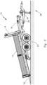
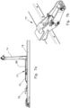
- Fig. 1 shows a first hook lift vehicle 10.
- the hook lift vehicle 10 is designed as a vehicle trailer, which is usually moved in a direction of travel F.
- a container 12 is loaded on the hook lift vehicle 10.
- the container 12 is designed as a trough.
- the hook lift vehicle 10 has a hook lift 14 which is arranged on an intermediate frame 16 .
- the hook lift 14 is designed to be telescopic in the longitudinal direction of the intermediate frame 16. Im in Fig. 1 In the state shown, the intermediate frame 16 rests on a chassis 18 .
- the chassis 18 has a means of an adjusting cylinder (in Fig. 1 not visible) along the longitudinal direction L corresponding to the direction of travel F on a (in Fig. 1 also not visible) guide rail adjustable, in particular hydraulically adjustable, axis 19 .
- tilting cylinders 20 Between the intermediate frame 16 and the chassis 18 there are two tilting cylinders 20 (see also Fig. 8 ) arranged, of which in the side view according to Fig. 1 only a tilt cylinder 20 can be seen.
- the tilt cylinders 20 are designed as double-acting hydraulic cylinders. Im in Fig. 1 In the state shown in which the tilting cylinders 20 are in the retracted state, the tilting cylinders 20 clamp the intermediate frame 16 onto the chassis 18 and thereby fix the intermediate frame 16 on the chassis 18.
- the tilting cylinders 20 can be designed as hydraulic cylinders.
- guide rollers 17 are arranged in its rear area for guiding the container 12 during unloading and/or loading from or onto the hook lift vehicle 10.
- Locks 21 are arranged in all corner areas of the chassis 18. Of these you can see the side view Fig. 1 only two locks 21 are shown.
- the locks 21 are in this Embodiment designed as a particularly controllable bolt lock.
- the locks 21 thus releasably connect the intermediate frame 16 to the chassis 18. In the closed or locked state, they each form pivot bearings. If the respective locks 21 are locked by means of suitable bolts on a first long side of the hook lift vehicle 10 and the corresponding locks 21 are opened on the other long side of the hook lift vehicle 10, the intermediate frame 16 can be tilted towards the first long side by extending the tilt cylinders 20 .
- the loaded container 12 can be tilted either to the left or right long side of the hook lift vehicle 10 using the side tipping device 22.
- the chassis 18 also has a two-axle pendulum axle unit 23 .
- a drawbar 24 of the chassis 18 is pivotally mounted relative to the rest of the chassis 18 by means of a connection 26 and with a pivoting mechanism 28 comprising a hydraulic cylinder.
- the chassis 18 - as will also be explained in more detail below - is designed to be lowerable overall.
- the rear or rear part of the chassis 18 corresponding to the direction of travel F can be lowered towards the floor 29 .
- the hook lift vehicle 10 points in the direction of travel F front side has a connecting section 30 with a towing eye 32 .
- the position of the connecting section 30 - and thus the towing eye 32 - can be adjusted along the longitudinal direction L and in the height direction H orthogonal to the longitudinal direction L.
- the towing eye 32 and thus the hook lift vehicle 10 can thus be adapted to different towing vehicles as required.
- the hook lift vehicle 10 can be supported on the ground 29, especially when the towing vehicle is not attached.
- the hook lift vehicle 10, in particular the chassis 18, has a lighting carrier 38 on its rear side.
- the lighting carrier 38 is displaceable along the longitudinal direction L on the rest of the chassis 18.
- it is by means of a hydraulic cylinder (in Fig. 1 not visible) can be moved.
- it can also be designed to be fixable, for example by means of clamping devices or by means of screw connections in conjunction with rows of holes arranged in the longitudinal direction L and incorporated into the rest of the chassis 18.
- Support wheels 39 can also be seen at the rear of the hook lift vehicle 10.
- support elements for example support feet, can also be provided instead of the support wheels 39.
- the support wheels 39 serve in particular to support the hook lift vehicle 10, especially when the chassis 18 is lowered towards the ground at the rear.
- the support wheels 39 also help to avoid lifting and/or tipping of the towing vehicle, particularly while loading and/or unloading the container 12.
- the hook lift vehicle 10 can be operated remotely using a radio remote control 40 .
- the hook lift vehicle 10 has a receiving and control unit 42 on its chassis 18.
- the receiving and control unit 42 is set up to receive and evaluate control signals 44 transmitted by radio from the radio remote control 40.
- the receiving and control unit 42 is also set up, depending on these control signals 44, to operate the tilting cylinders 20, the pivoting mechanism 28, the hook lift 14, the locks 21, in particular to open or close them on one long side of the hook lift vehicle 10 as required. It is also set up to operate all other operable elements related to the container 12, for example the hydraulic cylinder for moving the lighting carrier 38 and/or the adjusting cylinder of the adjustable axle 19, as required.
- the hook lift 14 has a hook 46 at one end.
- the hook 46 is designed with an elliptical, open internal cross section.
- a resiliently mounted closure element 47 serves to automatically close the opening of the hook 46.
- the hook 46 is designed as an automatic hook.
- the container 12 has a handle element 48 .
- the handle element 48 is shaped like a semi-ring and is arranged on the container 12 in a position adapted to the hook 46 or the hook lift 14.
- the container 12 has several side walls, in particular two side walls 50 on each of its two long sides On the back there is a rear side wall 52 and on its front side there is a front side wall 54.
- the side side walls 50 are secured by means of several side wall closures 56, of which, for reasons of illustration, are shown in the illustration Fig. 1 only four side wall closures 56 are marked with reference numbers, and are arranged to be swingable and foldable on the container 12 by means of several side wall hinges 58, of which only one side wall hinge 58 is also provided with a reference number for reasons of illustration.
- the side walls 50 are each divided into two parts.
- the rear side wall 52 is arranged on the rest of the container 12 so that it can be oscillated, folded down and pivoted laterally by means of a rear wall closure 60, several rear wall hinges 62 and a rear wall pivot joint 64 . In particular, it can be used as an access ramp when folded down.
- the handle element 48 Adjacent to the front side wall 54 there is a supporting wall 55 of a main frame supporting the container.
- the handle element 48 is arranged at a height position that is coordinated with the hook lift 14, in particular with the position of the hook 46.
- the support wall 55 is higher than the height position of the handle element 48.
- floor rollers 66 are also arranged, through which the container 12 can roll on the floor 29, in particular during unloading and/or loading.
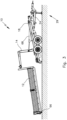
- Fig. 2 shows a position of the hook lift vehicle 10 Fig. 1 , in which, for example, a mobile work machine (in Fig. 2 not shown) can be easily loaded and/or unloaded.
- the chassis 18 is lowered towards the ground 29 at the rear by means of the pendulum axle unit 23 and the pivoting mechanism 28 arranged on the drawbar 24. Due to the lowering, the container 12 is also inclined towards the horizontal; In particular, it is also lowered towards the floor 29 at the rear.
- the mobile work machine or the load can thus be moved into or out of the container 12 via the rear side wall 52.
- Fig. 3 shows the hook lift vehicle 10 in a position during the unloading of the container 12. This position can also be used accordingly for or during loading of the container 12 onto the hook lift vehicle 10.
- the drawbar 24 is pivoted against the chassis 18, so that the hook lift vehicle 10 is lowered towards the ground 29 at the rear. Due to the lowering, the parking space requirement behind the hook lift vehicle 10 is reduced in this application. In addition, the maximum inclination of the container against the horizontal during unloading is reduced.
- the Fig. 3 It can also be seen that the hook lift 14, which is L-shaped in the side view, is powered by two hydraulic cylinders 68, one of which is shown in the illustration Fig. 3 only one can be seen being driven.
- the container 12 can therefore be unloaded as follows (the same applies in the reverse order of the steps to load the container 12):
- the hook lift vehicle 10 or the chassis 18 is lowered at the rear.
- the telescopic hook lift 14 is fully retracted so that the container 12 is moved beyond the rear end of the hook lift vehicle 10.
- the hook lift 14 is erected, whereby the container 12 rolls on the floor rollers 66 and leaves the hook lift vehicle 10 in a pivoting movement.
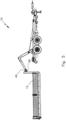
- Fig. 4 represents an alternative use option for unloading or loading the container 12 from or onto the hook lift vehicle 10.
- This alternative largely corresponds to the application Fig. 3 .
- the only difference is that in this alternative the drawbar 24 is not pivoted against the chassis 18.
- the hook lift vehicle 10 is therefore not lowered at the rear.
- the container 12 can be adjusted accordingly Fig.3 Unload or load using the procedure described.
- the container 12 is tilted more towards the horizontal during the erection of the hook lift 14 than in the application described above.
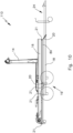
- Fig. 5 shows the final state of the in relation to Fig. 4 described application after the container 12 has been unloaded from the hook lift vehicle 10, but before the hook 46 has been unhooked from the handle element 48.
- the in Fig. 5 The state shown can also serve as the initial state before loading the container 12 onto the hook lift vehicle 10.
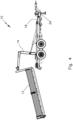
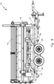
- Fig. 6 shows an application in which, for example, bulk goods can be unloaded or poured at the rear. For this purpose, the hook lift vehicle 10 is not lowered.
- the hook lift 14 has an upper arm part 70 which is articulated to a lower arm part 74 via a joint 72 .
- the upper arm part 70 forms an articulated arm with the joint 72 and the lower arm part 74.
- the lower arm part 74 is in turn articulated to the intermediate frame 16 at its rear end.
- the hydraulic cylinder 68 engages the upper arm part 70.
- the container 12 is fixed to the hook lift 14.
- the arm lock (not shown) additionally fixes the lower arm part 74 on the underside of the container 12, so that the hook lift 14 is prevented from bending while the container 12 is being erected.
- the container 12 can have one or more T or U profiles on its underside which, for example, can engage a controllable bolt of the arm lock or can be released from it.
- FIG. 7a Shown in a schematic detailed view Fig. 7a the hook lift 14 of the hook lift vehicle 10 ( Fig. 1 ).
- the hook lift 14 rests on the intermediate frame 16.
- the hydraulic cylinder 68 engages the upper arm part 70.
- several container locks can be seen, arranged in particular along the long sides of the intermediate frame 16, of which in particular one, in particular the rear, container lock 76 and a front container lock 77 in the illustration Fig. 7a are marked.
- the container locks in particular the container locks 76, 77, the container can be releasably secured to the intermediate frame 16.
- the hook lift vehicle may only have rear container latches 76.
- FIG. 7b an exemplary perspective view of the front container lock 77, which is designed as a hydraulically actuated bolt lock.
- At least one of the container locks 76, 77 can also be designed as a manually operated bolt lock. For this purpose, it can have a manually removable and/or manually insertable locking pin. This means costs can be reduced.
- At least one of the locks 21 ( Fig. 1 ) and/or the container locks 76, 77 can have a status sensor.
- the state sensor can be set up to detect the state in which the respective lock 21 or container lock 76, 77 is located. In particular, it can be set up to detect whether it is in a locked or unlocked state.
- the status sensor can have a proximity switch and/or be designed as a proximity switch. In particular, it can be designed as an electronic sensor.
- each of the locks 21 and/or each of the container locks 76, 77 can be equipped with such a status sensor.
- the condition sensor can be connected to a central control unit of the hook lift vehicle 10.
- the central control unit is and the status sensor can be designed to enable and/or block one of the functionalities of the hook lift vehicle 10, for example tipping the container backwards and/or towards one of the long sides.
- the release or blocking can take place depending on the state of the respective lock 21 or container lock 76, 77, in particular detected by the status sensor.
- Fig. 8 shows the hook lift vehicle 10 in a side view with the container 12 tilted to the left. In this position, the hook lift vehicle 10 can be used as a side tipper, for example for pouring bulk goods to the side.
- the tilt cylinders 20 engage the intermediate frame 16 via rocker arms 78 .
- the locks 21 located along the left long side of the hook lift vehicle 10 are in the in Fig. 8 locked in the state shown.
- the intermediate frame 16 and thus also the container 12 can be tilted or tilted to the left side of the hook lift vehicle 10.
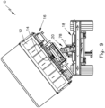
- Fig. 9 shows the hook lift vehicle 10 from behind in the position shown Fig. 8 . What can be seen in particular is the inclination of the container 12 towards the left side.
- the intermediate frame 16 when tilting to the side, the intermediate frame 16 is tilted sideways together with the hook lift 14.
- the tilt cylinders 20 are supported by the rocker arms 78 Chassis 18 and lift the intermediate frame 16 upwards in an approximately central area.
- Fig. 10 and 11 show two further exemplary embodiments of the invention in the form of the hook lift vehicles 110 ( Fig. 10 ) and 210 ( Fig. 11 ).
- the representations are schematized to emphasize the particular principles underlying these embodiments. Unless otherwise described, features of the hook lift vehicle 10 can be implemented in an analogous manner on the hook lift vehicles 110 and/or 210.
- Both hook lift vehicles 110, 210 are in turn designed as trailers, although a truck version is also fundamentally conceivable.
- chassis 18 has a continuous drawbar 24. They also have an axle 19 designed as a tandem axle. The axis 19 can in turn be designed to be adjustable.
- a middle frame 80 is arranged between the intermediate frame 16, which is designed essentially analogously to the hook lift device 10, with the hook lift 14 and the chassis 18.
- the hook lift vehicle 110 has two - suitably shaped - tilting cylinders 20, in particular a tilting cylinder 20 in the area of the axis 19 and a tilting cylinder 20 located further forward.
- This front tilt cylinder 20 connects the center frame 80 to the chassis 18.
- the hook lift vehicle 210 only has one tilting cylinder 20 near the axle.
- the remaining tilting cylinders 20 in turn connect the chassis 18 with the intermediate frame 16 and/or with the hook lift 14.
- Both embodiments also have several locks 21, which can be designed essentially analogously to the locks 21 of the hook lift vehicle 10.
- the intermediate frame 16 together with the hook lift 14 - and thus also any loaded container - can be tilted laterally by actuating the respective tilting cylinder 20 near the axle, with locks 21 between the 18 along a long side of the respective chassis Intermediate frame 16 and the middle frame 80 are closed and opened along the other long side.
- the hook lift device 110 has, in particular in the area of the axis 19, one or more rows, here in particular two rows, of locks 21, which fix or lock the middle frame 80 on the chassis 18 in a releasable and rotatable manner.
- the middle frame 80 and thus the hook lift device 110 can be opened Intermediate frame 16 together with the hook lift 14 can be lowered at the rear.
- a lowering at the rear can also be achieved with the hook lift device 210.
- the front lock 79 must be opened and all locks 21, in particular the single row of locks 21 between the middle frame 80 and the chassis 18, must be closed. If the tilting cylinder 20 near the axle is now actuated, the middle frame 80 and thus the intermediate frame 16 are again lowered over the series of locks 21 and thus at the rear.
- Fig. 12 finally shows a fourth hook lift vehicle 310.
- the hook lift vehicle 310 is designed as a truck. In terms of its structure, it largely corresponds to the hook lift vehicle 10 ( Fig. 1 to Fig. 9 ). A significant difference is that instead of the towing eye 32, the flanges 34 and the support 36 (each Fig. 1 ) the remaining hook lift vehicle 310 is mounted on a truck chassis with a driver housing 81 and a front axle 82 as well as a drive. Thus, the hook lift vehicle 310 itself is motorized and does not require any additional towing vehicle to drive it.
- Fig. 12 It can be seen that the hook lift vehicle 310 is designed to have two axles in its loading section 84, in particular without taking into account the front axle 82 arranged in the area of the driver housing 81.
Landscapes
- Engineering & Computer Science (AREA)
- Transportation (AREA)
- Mechanical Engineering (AREA)
- Body Structure For Vehicles (AREA)
- Handcart (AREA)
- Fittings On The Vehicle Exterior For Carrying Loads, And Devices For Holding Or Mounting Articles (AREA)
- Details Of Rigid Or Semi-Rigid Containers (AREA)
Description
- Die Erfindung geht aus von einem Hakenliftfahrzeug mit einem Hakenlift zum Auf- und/oder Abladen eines Containers.
- Solche Hakenliftfahrzeuge sind beispielsweise in Form von Anhängern oder LKWs bekannt. Sie ermöglichen es, einen geeignet ausgebildeten Container mittels des Hakenlifts insbesondere heckseitig, d. h. hinter dem Hakenliftfahrzeug, abzuladen oder von hinten auf das Hakenliftfahrzeug aufzuladen.
- So kann ein Container beispielsweise mittels des Hakenliftfahrzeugs zu einer Baustelle transportiert, dort abgeladen, mit Ladegut, beispielsweise Bauschutt, befüllt und sodann wieder auf das Hakenliftfahrzeug aufgeladen und abtransportiert werden. Dabei kann ein und das gleiche Hakenliftfahrzeug für mehrere Container zeitparallel verwendet werden. So kann ein Container beispielsweise über mehrere Tage hinweg befüllt werden, während das Hakenliftfahrzeug an einem anderen Ort und/oder mit einem anderen Container verwendet wird.
- Bedingt dadurch, dass das Auf- und Abladen heckseitig des Hakenliftfahrzeugs erfolgt, erfordert der Einsatz eines Hakenliftfahrzeugs jedoch einen vergleichsweise großen Parkraum.
- Gerade im kommunalen als auch im landwirtschaftlichen Bereich und Baubereich ist es ferner üblich, für unterschiedliche Anwendungsfälle unterschiedliche Transportfahrzeuge bereitzuhalten. Hierdurch ergeben sich jedoch sehr hohe Kosten für die Bereitstellung und Wartung eines solchen Fuhrparks. Diese Kosten ließen sich reduzieren, wenn multifunktionale Transportfahrzeuge zum Einsatz kommen könnten. Wünschenswert wäre daher ein Hakenliftfahrzeug, mit dem in besonders vielfältiger Weise übliche Containergüter, beispielsweise Schüttgüter, Maschinen, usw. aufgeladen, abgeladen und/oder transportiert werden können.
- Aus der
DE 20 2013 103 654 U1 ist ein gattungsgemäßes Transportfahrzeug zum Aufnehmen und Absetzen eines Behälters bekannt. Auf das bekannte Transportfahrzeug kann ein Container mittels eines an einem Schlitten geführten Hakens aufgezogen werden. - Aus der
US 2012 / 0 025 590 A1 ist ein Fahrzeug bekannt, das einen Container heckseitig abladen kann. Darüber hinaus kann der Container seitlich abgekippt werden. - Die
US 2004 / 0083671 A1 offenbart einen Container, dessen Seitenwände um eine untere parallel zur Längsachse verlaufende Achse abklappbar sind. - Aufgabe der vorliegenden Erfindung ist es daher, ein Hakenliftfahrzeug mit erweiterten Nutzungsmöglichkeiten bereitzustellen.
- Gelöst wird diese Aufgabe durch ein Hakenliftfahrzeug mit den Merkmalen des Patentanspruchs 1.
- Der Hakenlift kann insbesondere zum heckseitigen Auf- und/oder Abladen des Containers eingerichtet sein. Der Hakenlift kann einteilig oder mehrteilig, insbesondere ein- oder mehrarmig, ausgebildet sein. Er kann ausgebildet sein, den Container an dessen Vorderseite zu greifen. Alternativ oder ergänzend kann der Hakenlift auch im Bereich einer oder beider Längsseiten des Hakenliftfahrzeugs angeordnet sein. Insbesondere kann er dann ausgebildet sein, den Container an dessen Seitenwänden zu greifen.
- Ein solches Hakenliftfahrzeug bietet eine Vielzahl von Nutzungsmöglichkeiten. So kann der Container insbesondere heckseitig auf- und/oder abgeladen werden. Mittels des Hakenlifts kann der Container alternativ auch nach hinten abgekippt werden. Dazu kann das Hakenliftfahrzeug als Abrollkippfahrzeug ausgebildet sein.
- Soweit das Hakenliftfahrzeug eingerichtet ist, den aufgeladenen Container entlang der wenigstens einen Längsseite des Hakenliftfahrzeugs seitlich abzukippen, kann der Container, beispielsweise wenn hinter dem Hakenliftfahrzeug nur wenig Raum zur Verfügung steht, auch entlang der Längsseite des Hakenliftfahrzeugs be- und/oder entladen werden. Bei einem solchen Hakenliftfahrzeug können somit beispielsweise auch Schüttgüter zusätzlich zum bisher üblichen heckseitigen Abladen des befüllten Containers zusätzlich bzw. alternativ über wenigstens eine Längsseite abgekippt werden. Somit kann das Hakenliftfahrzeug auch als Mehrseitenkipper genutzt werden.
- Soweit das Hakenliftfahrzeug heckseitig absenkbar ausgebildet ist, können beispielsweise fahrbare Arbeitsmaschinen auf das heckseitig abgesenkte Hakenliftfahrzeug einfacher aufgefahren und/oder von diesem heruntergefahren werden. Insbesondere kann das Hakenliftfahrzeug ein heckseitig absenkbares Fahrgestell aufweisen.
- Somit sind die Verwendungsmöglichkeiten eines erfindungsgemäßen Hakenliftfahrzeugs gegenüber einem herkömmlichen Hakenliftfahrzeug deutlich erweitert. In kommunalen als auch in landwirtschaftlichen Bereichen lässt sich der Nutzungsgrad eines solchen Hakenliftfahrzeugs verbessern, wodurch sich erhebliche Kostenvorteile ergeben können und/oder wodurch sich die Amortisationsdauer eines Hakenliftfahrzeugs für den Verwender verkürzt.
- Dazu kann das Hakenliftfahrzeug eine Seitkippvorrichtung zum seitlichen Abkippen des aufgeladenen Containers entlang der wenigstens einen Längsseite des Hakenliftfahrzeugs aufweisen.
- Die Seitkippvorrichtung kann eingerichtet sein, den Container wahlweise zur linken oder zur rechten Längsseite des Hakenliftfahrzeugs abzukippen. Unter linker bzw. rechter Seite bzw. Längsseite kann dabei die jeweilige Seite bei Blick entlang der üblichen Fahrtrichtung des Hakenliftfahrzeugs verstanden werden.
- Der Container kann somit wahlweise sowohl von der linken als auch von der rechten Seite aus be- und/oder entladen werden. Somit kann das Hakenliftfahrzeug auch als weiter verbesserter Mehrseitenkipper, insbesondere als Dreiseitenkipper, beispielsweise in der Landwirtschaft, genutzt werden.
- Denkbar ist insbesondere, dass die Seitkippvorrichtung wenigstens einen, insbesondere ein oder zwei, Kippzylinder aufweist. Die Kippzylinder können beispielsweise hydraulisch oder pneumatisch betätigbar sein. Durch solche Kippzylinder kann ein hoher Hub erzielt werden bei gleichzeitig geringem Platzbedarf, insbesondere in Höhenrichtung. Somit kann eine ausreichende Bodenfreiheit gewährleistet werden.
- Wenigstens einer der Kippzylinder kann als doppeltwirkender Zylinder ausgebildet sein. Somit kann der Kippzylinder, insbesondere in seinem eingefahrenen Zustand, auch zur Fixierung der Seitkippvorrichtung, des Hakenlifts und/oder des Containers an einem Fahrgestell des Hakenliftfahrzeugs verwendet werden.
- Die Seitkippvorrichtung umfasst einen seitlich abkippbaren Zwischenrahmen, an dem der Hakenlift oder wenigstens ein Teil des Hakenlifts angeordnet ist. Insbesondere kann dann der wenigstens eine Kippzylinder zwischen dem Fahrgestell und dem Zwischenrahmen angeordnet sein. Dann kann der wenigstens eine Kippzylinder - durch Ausfahren des Kippzylinders - den Zwischenrahmen mitsamt dem an diesem angeordneten Hakenlift sowie gegebenenfalls einem aufgeladenen Container seitlich abkippen oder - durch Einfahren des Kippzylinders - den Zwischenrahmen samt Hakenlift und gegebenenfalls Container in seine horizontale Ausgangslage zurückbewegen. Auch kann der wenigstens eine doppeltwirkende Kippzylinder, beispielsweise vor Betätigen des Hakenlifts, insbesondere in eingefahrenem Zustand, den Zwischenrahmen auf das Fahrgestell spannen und damit den Hakenlift und somit auch den Container gegen ein seitliches und/oder gegen ein heckseitiges Abkippen fixieren.
- Die Seitkippvorrichtung kann wenigstens zwei Verriegelungen, vorzugsweise Bolzen- oder Krampenverriegelungen, aufweisen, die eingerichtet sind, den aufgeladenen Container, insbesondere durch drehbares Festlegen des Zwischenrahmens, an einer Längsseite des Hakenliftfahrzeugs drehbar festzulegen. Somit kann der Container, insbesondere mittels des Zwischenrahmens, an dieser Längsseite drehbar am Hakenliftfahrzeug, insbesondere an seinem Fahrgestell, festgelegt werden. Wird sodann der bzw. werden sodann die Kippzylinder ausgefahren, kann der Container, insbesondere mittels des Zwischenrahmens, zu dieser Längsseite hin abgekippt werden. Ein oder mehrere der Verriegelungen können hydraulisch und/oder pneumatisch betätigbar sein. Dann kann der seitliche Abkippvorgang automatisiert und/oder "per Knopfdruck" gesteuert werden.
- Besonders günstig ist es, wenn wenigstens vier derartige Verriegelungen, insbesondere jeweils wenigstens zwei Verriegelungen auf jeder der beiden Längsseiten des Hakenliftfahrzeugs, vorgesehen sind. Somit ist es möglich, den Container, insbesondere mittels des Zwischenrahmens, wahlweise an jeder der beiden Längsseiten des Hakenliftfahrzeugs drehbar festzulegen, sodass auf besonders einfache Weise ein seitliches Abkippen wahlweise sowohl zur rechten als auch zur linken Seite hin ermöglicht wird. Denkbar ist dann auch, dass, um den Container bzw. den Zwischenrahmen auf das Fahrgestell zu spannen alternativ oder ergänzend Verriegelungen entlang beider Längsseiten verriegelt werden. Zusätzlich kann, insbesondere für diesen Fall, wenigstens ein Abschaltventil zur Abschaltung eines oder mehrerer der Kippzylinder vorgesehen sein.
- Bei einer besonders bevorzugten Klasse von Ausführungsformen der Erfindung ist vorgesehen, dass der Hakenlift teleskopierbar ist. Dazu kann der Hakenlift entlang einer Längsrichtung des Hakenliftfahrzeugs und/oder senkrecht oder im Wesentlichen senkrecht zu dieser, insbesondere vertikal, teleskopierbar sein. Insbesondere kann der Hakenlift derart vertikal teleskopierbar sein, dass die Höhenlage seines Hakens an ein oder mehrere Standardhöhen, beispielsweise 1570 und/oder 900 mm, von Griffelementen von Containern, anpassbar ist. Der Hakenlift kann hydraulisch und/oder pneumatisch teleskopierbar sein.
- Somit kann das Hakenliftfahrzeug für unterschiedliche Arten von Containern, insbesondere für unterschiedlich lange Container und/oder Container mit unterschiedlich hoch angeordneten Griffelementen, verwendet werden. Auch hierdurch lassen sich die Einsatzmöglichkeiten des Hakenliftfahrzeugs zusätzlich erweitern. Das Auf- und/oder Abladen des Containers kann vereinfacht werden.
- Während der Haken des Hakenlifts üblicherweise die Form eines geöffneten, näherungsweise elliptischen Ringes aufweisen kann, mit dem er den Container an einem geeignet komplementär ausgebildeten Griffelement greifen kann, ist es auch denkbar, den Haken in anderer Form auszubilden. Beispielsweise kann der Haken alternativ oder ergänzend als Rastelement, beispielsweise karabinerförmig, und/oder zangenförmig, insbesondere mit ein oder mehreren, relativ zueinander bewegbaren Teilen, ausgebildet sein. Der Haken kann besonders bevorzugt als Automatik-Haken ausgebildet sein.
- Bei einer besonders bevorzugten Klasse von Ausführungsformen weist das Hakenliftfahrzeug ein heckseitig absenkbares Fahrgestell auf. Vorzugsweise kann das Fahrgestell heckseitig zum Boden hin abgesenkt werden. Dies kann das Auf- und/oder Abladen des Containers erleichtern. Auch kann der Container mit einer geringeren maximalen Neigung gegen die Horizontale auf- bzw.- abgeladen werden. Ferner lässt sich hierdurch der Parkraumbedarf reduzieren.
- Dazu kann das Fahrgestell ein Pendelachsaggregat, ein Luftfederaggregat und/oder ein Parabelfederaggregat aufweisen und/oder - insbesondere, wenn es sich bei dem Hakenliftfahrzeug um einen Anhänger handelt - eine Deichsel des Hakenliftfahrzeugs kann relativ zum Fahrgestell verschwenkbar ausgebildet sein.
- Des Weiteren kann vorgesehen sein, dass das Hakenliftfahrzeug, insbesondere heckseitig, einen verstellbaren, insbesondere entlang des Fahrgestells verschiebbaren, Beleuchtungsträger aufweist. Somit lässt sich das Hakenliftfahrzeug zusätzlich an unterschiedliche, insbesondere unterschiedlich lange, Container anpassen. Vorzugsweise kann der Beleuchtungsträger elektrisch, hydraulisch und/oder pneumatisch verschiebbar ausgebildet sein.
- Denkbar ist auch, dass das Hakenliftfahrzeug als Anhänger oder als Lkw ausgebildet ist. Als Anhänger kann es zusammen mit unterschiedlichsten Zugfahrzeugen eingesetzt werden. Ist es als Lkw ausgebildet, wird kein weiteres Zugfahrzeug benötigt.
- Das Hakenliftfahrzeug kann - insbesondere in Abhängigkeit der beabsichtigten maximalen Zuladung - in seinem Ladeabschnitt ein-, zwei- oder dreiachsig ausgebildet sein. Es versteht sich, dass insbesondere bei einem als Lkw ausgebildeten Hakenliftfahrzeug weitere Achsen außerhalb des Ladeabschnitts, insbesondere im Bereich des Fahrergehäuses, vorgesehen sein können.
- Ein besonders vielseitig verwendbarer Container kann wenigstens eine pendelbare und abklappbare seitliche Bordwand und eine pendelbare und abklappbare heckseitige Bordwand aufweisen.
- Wenigstens eine seiner Achsen seines Ladeabschnitts kann entlang der Längsrichtung verstellbar, insbesondere hydraulisch verstellbar, sein. Ist das Hakenliftfahrzeug beispielsweise als Anhänger ausgebildet, so kann durch Verstellen der Achse ein Gewichtsausgleich erzielt werden. Insbesondere kann die auf eine Zugöse des Anhängers wirkende Stützlast eingestellt werden.
- Das Hakenliftfahrzeug lässt sich besonders einfach bedienen, wenn wenigstens eine seiner Funktionalitäten, insbesondere Aufladen, Abladen, heckseitiges Absenken und/oder seitliches Abkippen des Hakenliftfahrzeugs, Öffnen und/oder Schließen des Containers, Öffnen und/oder Schließen wenigstens einer der Verriegelungen, Verstellen der Achse und/oder Verstellen des Beleuchtungsträgers, fernsteuerbar, insbesondere mittels einer Funkfernsteuerung, ist. Allgemein ist denkbar, dass wenigstens eines der betätigbaren Elemente, insbesondere der elektrisch, hydraulisch und/oder pneumatisch betätigbaren Elemente, fernsteuerbar ausgebildet sein kann. Bei beispielsweise hydraulisch und/oder pneumatisch betätigbaren Elementen kann insbesondere ein jeweiliger pneumatischer oder hydraulischer Betätigungszylinder des betreffenden Elementes fernsteuerbar ausgebildet sein.
- Auch ist es beispielsweise denkbar, dass das Hakenliftfahrzeug, insbesondere die Funkfernsteuerung, einen Wählschalter aufweist, mit dem wenigstens eine dieser Funktionalitäten auslösbar und/oder steuerbar ist.
- Ein Container für ein erfindungsgemäßes Hakenliftfahrzeug kann sowohl ein heckseitiges Abladen und/oder Aufladen mittels eines Hakenlifts des Hakenliftfahrzeugs als auch eine Nutzung des Hakenliftfahrzeugs als Seitenkipper, insbesondere als Zweiseitenkipper oder - insbesondere wenn beide seitlichen Bordwände öffenbar sind - als Dreiseitenkipper, ermöglichen. Der Container weist eine seitliche Bordwand auf, diese kann auch mehrfach, insbesondere zweifach, geteilt sein, so dass die Bordwand in zwei oder mehr Teilen, insbesondere Flügeln, öffenbar ist. Ist wenigstens eine seitliche Bordwand abklappbar, so lassen sich beispielsweise auch nicht schüttbare Güter einfach ein- und entladen.
- Bei einem solchen Container kann insbesondere vorgesehen sein, dass seine heckseitige Bordwand pendelbar und/oder abklappbar, besonders bevorzugt pendelbar und abklappbar, und/oder wenigstens zu einer Seite hin verschwenkbar ist. Insbesondere kann die heckseitige Bordwand ähnlich einer Türe zur linken und/oder rechten Seite verschwenkbar sein. Denkbar ist auch, dass die heckseitige Bordwand mehrfach geteilt ist; beispielsweise kann die heckseitige Bordwand zweiflügelig gebildet sein. Dann kann die heckseitige Bordwand ähnlich einer zweiflügeligen Türe geöffnet werden, indem jeweils ein Flügel der Bordwand nach links und ein Flügel nach rechts geschwenkt wird.
- Dadurch lässt sich die heckseitige Bordwand je nach Anwendungsfall geeignet öffnen. Beispielsweise kann sie zur Ausbildung einer Auffahrrampe, beispielsweise zum Aufladen von fahrbaren Arbeitsmaschinen, abgeklappt werden. Zum Entladen von Schüttgut kann die heckseitige Bordwand pendelnd geöffnet werden. Sollen beispielsweise größere Güter aufgeladen oder abgeladen werden, besteht zudem die Möglichkeit, die heckseitige Bordwand je nach Bedarf zur linken oder zur rechten Seite zu verschwenken oder - bei einer zweiflügeligen Bordwand - jeweils einen Flügel nach links und einen nach rechts zu verschwenken. Denkbar ist insbesondere, dass ein oder mehrere Bordwände über eine vorzugsweise steuerbare Verriegelung und/oder über eine Zentralverriegelung öffenbar sind. Insbesondere kann auch vorgesehen sein, dass die Funkfernsteuerung und/oder das Hakenliftfahrzeug eingerichtet sind, ein oder mehrere der Bordwände des Containers zu öffnen und/oder zu schließen.
- Ferner ist es denkbar, dass insbesondere je nach beabsichtigtem Haupt-Einsatzbereich der Container als Mulde oder als Plattform-Container ausgebildet ist.
- Auch können Container mit dem Hakenliftfahrzeug verwendet werden, wenn sie als Halfpipe-Container, als Schuttmulde, als Häckselmulde, beispielsweise mit Gittern und/oder Planen, als Flüssigkeitscontainer oder dergleichen ausgebildet sind.
- Am Container und/oder am Hakenliftfahrzeug kann wenigstens eine insbesondere abnehmbare Auffahrrampe angeordnet sein. Bevorzugt können zwei solche Auffahrrampen vorgesehen sein. Dazu kann der Container und/oder das Hakenliftfahrzeug eine entsprechende Anzahl Auffahrrampenhalterungen zur Aufnahme und zum Transport der Auffahrrampen aufweisen. Solche Auffahrrampen können das Auffahren in den Container und/oder Herunterfahren vom Container von beispielsweise fahrbaren Arbeitsmaschinen zusätzlich erleichtern.
- Weitere Merkmale und Vorteile der Erfindung ergeben sich aus der nachfolgenden detaillierten Beschreibung der Ausführungsbeispiele der Erfindung, anhand der Figuren der Zeichnung, die erfindungswesentliche Einzelheiten zeigt, sowie aus den Ansprüchen.
- Die in der Zeichnung dargestellten Merkmale sind derart dargestellt, dass die erfindungsgemäßen Besonderheiten deutlich sichtbar gemacht werden können. Die verschiedenen Merkmale können je einzeln für sich oder zu mehreren in beliebigen Kombinationen bei Varianten der Erfindung verwirklicht sein.
- Es zeigen:
- Fig. 1
- eine Seitenansicht eines ersten, als Anhänger ausgebildeten Hakenliftfahrzeugs mit einem auf das Hakenliftfahrzeug aufgeladenen Container;
- Fig. 2
- eine Seitenansicht des Hakenliftfahrzeugs der
Fig. 1 in einer abgesenkten Stellung mit abgeklappter heckseitiger Bordwand; - Fig. 3
- eine Seitenansicht des Hakenliftfahrzeugs der
Fig. 1 in einer abgesenkten Stellung während des Entladens des Containers; - Fig. 4 und 5
- Seitenansichten des Hakenliftfahrzeugs der
Fig. 1 in nichtabgesenkten Stellungen während des Entladens des Containers; - Fig. 6
- eine Seitenansicht des Hakenliftfahrzeugs der
Fig. 1 in einer nicht-abgesenkten Stellung mit nach hinten abgekipptem Container; - Fig. 7a
- eine Detailansicht eines Hakenlifts und eines Zwischenrahmens des Hakenliftfahrzeugs der
Fig. 1 als schematische Seitenansicht; - Fig. 7b
- eine Containerverriegelung in schematischer, perspektivischer Darstellung;
- Fig. 8
- eine Seitenansicht des Hakenliftfahrzeugs der
Fig.1 in einer Stellung mit nach links abgekipptem Container; - Fig. 9
- eine Ansicht von hinten auf das Hakenliftfahrzeug der
Fig. 1 in der Stellung gemäßFig. 8 ; - Fig. 10 und 11
- schematische Seitenansichten zweier weiterer als Anhänger ausgebildeter Hakenliftfahrzeuge und
- Fig. 12
- eine Seitenansicht eines vierten, als LKW ausgebildeten Hakenliftfahrzeugs in einer Stellung mit nach links abgekipptem Container.
- Zur Erleichterung des Verständnisses der Erfindung sind, soweit nicht anders genannt, sich entsprechende Elemente in allen Figuren der Zeichnung sowie in der nachfolgenden Beschreibung mit denselben Bezugszeichen bezeichnet.
-
Fig. 1 zeigt ein erstes Hakenliftfahrzeug 10. Das Hakenliftfahrzeug 10 ist in diesem Ausführungsbeispiel als Fahrzeuganhänger ausgebildet, der üblicherweise in einer Fahrtrichtung F bewegt wird. Auf dem Hakenliftfahrzeug 10 ist ein Container 12 aufgeladen. Der Container 12 ist als Mulde ausgebildet. - Das Hakenliftfahrzeug 10 weist einen Hakenlift 14 auf, der an einem Zwischenrahmen 16 angeordnet ist. Der Hakenlift 14 ist in Längsrichtung des Zwischenrahmens 16 teleskopierbar ausgebildet. Im in
Fig. 1 dargestellten Zustand liegt der Zwischenrahmen 16 auf einem Fahrgestell 18 auf. - Das Fahrgestell 18 weist eine mittels eines Verstellzylinders (in
Fig. 1 nicht sichtbar) entlang der der Fahrtrichtung F entsprechenden Längsrichtung L auf einer (inFig. 1 ebenfalls nicht sichtbaren) Führungsschiene verstellbare, insbesondere hydraulisch verstellbare, Achse 19 auf. - Zwischen dem Zwischenrahmen 16 und dem Fahrgestell 18 sind zwei Kippzylinder 20 (s. auch
Fig. 8 ) angeordnet, von denen in der Seitenansicht gemäßFig. 1 lediglich ein Kippzylinder 20 erkennbar ist. Die Kippzylinder 20 sind als doppeltwirkende Hydraulikzylinder ausgebildet. Im inFig. 1 dargestellten Zustand, in dem sich die Kippzylinder 20 in eingefahrenem Zustand befinden, spannen die Kippzylinder 20 den Zwischenrahmen 16 auf das Fahrgestell 18 auf und fixieren dadurch den Zwischenrahmen 16 am Fahrgestell 18. Die Kippzylinder 20 können als Hydraulikzylinder ausgebildet sein. - Sowohl links- als auch rechtsseitig des Zwischenrahmens 16 sind an diesem in seinem hinteren Bereich Führungsrollen 17 zur Führung des Containers 12 während des Ab- und/oder Aufladens vom bzw. auf das Hakenliftfahrzeug 10 angeordnet.
- In allen Eckbereichen des Fahrgestells 18 sind Verriegelungen 21 angeordnet. Von diesen sind in der Seitenansicht der
Fig. 1 lediglich zwei Verriegelungen 21 dargestellt. Die Verriegelungen 21 sind in diesem Ausführungsbeispiel als insbesondere steuerbare Bolzenverriegelungen ausgebildet. Die Verriegelungen 21 verbinden somit den Zwischenrahmen 16 lösbar mit dem Fahrgestell 18. Sie bilden in geschlossenem bzw. verriegeltem Zustand jeweils Drehlager. Sind somit auf einer ersten Längsseite des Hakenliftfahrzeugs 10 die jeweiligen Verriegelungen 21 mittels geeigneter Bolzen verriegelt und auf der anderen Längsseite des Hakenliftfahrzeugs 10 die entsprechenden Verriegelungen 21 geöffnet, so lässt sich der Zwischenrahmen 16 zu der ersten Längsseite hin abkippen, indem die Kippzylinder 20 ausgefahren werden. - Der Zwischenrahmen 16 bildet somit in Verbindung mit den Kippzylindern 20 und den Verriegelungen 21 insgesamt eine Seitkippvorrichtung 22 zum wahlweisen, seitlichen Abkippen des aufgeladenen Containers 12 entlang der ersten oder der anderen Längsseite. Mit anderen Worten lässt sich mithilfe der Seitkippvorrichtung 22 der aufgeladene Container 12 wahlweise zur linken oder rechten Längsseite des Hakenliftfahrzeugs 10 abkippen.
- Weiter weist das Fahrgestell 18 ein zweiachsiges Pendelachsaggregat 23 auf. Eine Deichsel 24 des Fahrgestells 18 ist mittels einer Anbindung 26 sowie mit einer einen Hydraulikzylinder umfassenden Verschwenkmechanik 28 relativ zum übrigen Fahrgestell 18 verschwenkbar gelagert. Somit ist das Fahrgestell 18 - wie ebenfalls weiter unten noch näher erläutert wird - insgesamt absenkbar ausgebildet. Insbesondere kann der entsprechend der Fahrtrichtung F hintere bzw. heckseitige Teil des Fahrgestells 18 zum Boden 29 hin abgesenkt werden.
- Zur Verbindung mit einem Zugfahrzeug (in
Fig. 1 nicht dargestellt) weist das Hakenliftfahrzeug 10 an seiner entsprechend der Fahrtrichtung F vorderen Seite einen Verbindungsabschnitt 30 mit einer Zugöse 32 auf. Mittels zweier Flansche 34 ist die Lage des Verbindungsabschnitts 30 - und damit der Zugöse 32 - entlang der Längsrichtung L sowie in der zur Längsrichtung L orthogonalen Höhenrichtung H verstellbar. Somit lässt sich die Zugöse 32 und damit das Hakenliftfahrzeug 10 je nach Bedarf an unterschiedliche Zugfahrzeuge anpassen. - Mittels einer an der Deichsel 24 angeordneten Stütze 36 kann das Hakenliftfahrzeug 10, insbesondere bei nicht angehängtem Zugfahrzeug, am Boden 29 abgestützt werden.
- Weiter weist das Hakenliftfahrzeug 10, insbesondere das Fahrgestell 18, an seiner hinteren Seite einen Beleuchtungsträger 38 auf. Der Beleuchtungsträger 38 ist entlang der Längsrichtung L verschiebbar am übrigen Fahrgestell 18 angeordnet. In diesem Ausführungsbeispiel ist er mittels eines Hydraulikzylinders (in
Fig. 1 nicht sichtbar) verschiebbar. In alternativen Ausführungsformen kann er auch, beispielsweise mittels Klemmvorrichtungen oder mittels Verschraubungen in Verbindung mit in Längsrichtung L angeordneten, in das übrige Fahrgestell 18 eingearbeiteten Lochreihen, festlegbar ausgebildet sein. - Heckseitig am Hakenliftfahrzeug 10 sind ferner Stützräder 39 zu erkennen. In alternativen Ausführungen der Erfindung können anstelle der Stützräder 39 auch Stützelemente, beispielsweise Stützfüße, vorgesehen sein. Die Stützräder 39 dienen insbesondere zur Abstützung des Hakenliftfahrzeugs 10, insbesondere wenn das Fahrgestell 18 heckseitig zum Boden hin abgesenkt ist. Auch tragen die Stützräder 39 dazu bei, ein Anheben und/oder Kippen des Zugfahrzeugs, insbesondere während des Auf- und/oder Abladens des Containers 12, zu vermeiden.
- Das Hakenliftfahrzeug 10 kann mittels einer Funkfernsteuerung 40 ferngesteuert bedient werden. Dazu weist das Hakenliftfahrzeug 10 an seinem Fahrgestell 18 eine Empfangs- und Steuerungseinheit 42 auf. Die Empfangs- und Steuerungseinheit 42 ist eingerichtet, von der Funkfernsteuerung 40 per Funk ausgesendete Steuerungssignale 44 zu empfangen und auszuwerten. Die Empfangs- und Steuerungseinheit 42 ist ferner eingerichtet, in Abhängigkeit dieser Steuerungssignale 44 die Kippzylinder 20, die Verschwenkmechanik 28, den Hakenlift 14, die Verriegelungen 21 zu betätigen, insbesondere je nach Bedarf auf jeweils einer Längsseite des Hakenliftfahrzeugs 10 zu öffnen oder zu schließen. Auch ist sie eingerichtet, alle weiteren im Zusammenhang mit dem Container 12 stehenden, betätigbaren Elemente, beispielsweise den Hydraulikzylinder zur Verschiebung des Beleuchtungsträgers 38 und/oder den Verstellzylinder der verstellbaren Achse 19, je nach Bedarf zu betätigen.
- Der Hakenlift 14 weist einenends einen Haken 46 auf. Der Haken 46 ist mit einem elliptischen, geöffneten inneren Querschnitt ausgebildet. Ein federnd gelagertes Verschlusselement 47 dient zum selbsttätigen Verschluss der Öffnung des Hakens 46. Insgesamt ist der Haken 46 als Automatik-Haken ausgebildet.
- Zur lösbaren Verbindung des Containers 12 mit dem Hakenlift 14 weist der Container 12 ein Griffelement 48 auf. Das Griffelement 48 ist halbringförmig geformt und in einer dem Haken 46 bzw. dem Hakenlift 14 angepassten Position am Container 12 angeordnet.
- Der Container 12 weist mehrere Bordwände auf, insbesondere auf jeder seiner beiden Längsseiten je zwei seitliche Bordwände 50, auf seiner Rückseite eine heckseitige Bordwand 52 sowie auf seiner Vorderseite eine vorderseitige Bordwand 54.
- Die seitlichen Bordwände 50 sind mittels mehrerer Bordwandverschlüsse 56, von denen aus Darstellungsgründen in der Darstellung der
Fig. 1 lediglich vier Bordwandverschlüsse 56 mit Bezugszeichen markiert sind, sowie mittels mehrerer Bordwandscharniere 58, von denen ebenfalls aus Darstellungsgründen lediglich ein Bordwandscharnier 58 mit einem Bezugszeichen versehen ist, pendelbar und abklappbar am Container 12 angeordnet. Die seitlichen Bordwände 50 sind jeweils zweigeteilt. - Die heckseitige Bordwand 52 ist mittels eines Rückwandverschlusses 60, mehreren Rückwandscharnieren 62 sowie einem Rückwandschwenkgelenk 64 pendelbar, abklappbar als auch seitlich verschwenkbar am übrigen Container 12 angeordnet. Insbesondere kann sie in abgeklapptem Zustand als Auffahrrampe genutzt werden.
- Angrenzend an die vorderseitige Bordwand 54 befindet sich eine Tragwand 55 eines den Container stützenden Hauptrahmens. An der Tragwand 55 ist das Griffelement 48 an einer auf den Hakenlift 14, insbesondere auf die Position des Hakens 46, abgestimmten Höhenposition angeordnet. Dazu ist in diesem Ausführungsbeispiel die Tragwand 55 höher als die Höhenposition des Griffelements 48.
- An der Unterseite des Containers 12 sind ferner im Bereich der heckseitigen Bordwand 52 Bodenrollen 66 angeordnet, durch die der Container 12 insbesondere während des Abladens und/oder während des Aufladens auf dem Boden 29 abrollen kann.
- In
Fig. 2 bis Fig. 9 werden beispielhaft weitere Nutzungsmöglichkeiten bzw. Anwendungsfälle des erfindungsgemäßen Hakenliftfahrzeugs 10 (Fig. 1 ) näher dargestellt. -
Fig. 2 zeigt eine Stellung des Hakenliftfahrzeugs 10 derFig. 1 , in der beispielsweise eine fahrbare Arbeitsmaschine (inFig. 2 nicht dargestellt) einfach auf- und/oder abgeladen werden kann. - Zu erkennen ist, dass das Fahrgestell 18 mittels des Pendelachsaggregats 23 und der an der Deichsel 24 angeordneten Verschwenkmechanik 28 heckseitig zum Boden 29 hin abgesenkt ist. Durch die Absenkung ist auch der Container 12 gegen die Horizontale geneigt; insbesondere ist auch er heckseitig zum Boden 29 hin abgesenkt.
- Durch teilweises Einfahren des teleskopierbaren Hakenlifts 14 ist der Container 12 in etwa zur Hälfte vom Fahrgestell 18 abgeladen. Zusätzlich ist die heckseitige Bordwand 52 zum Boden hin abgeklappt und bildet dadurch eine Auffahrrampe.
- Somit kann die fahrbare Arbeitsmaschine bzw. das Ladegut über die heckseitige Bordwand 52 in den Container 12 hinein- bzw. aus diesem herausgefahren werden.
-
Fig. 3 zeigt das Hakenliftfahrzeug 10 in einer Stellung während des Abladens des Containers 12. Diese Stellung kann auch für bzw. während des Aufladens des Containers 12 auf das Hakenliftfahrzeug 10 entsprechend genutzt werden. - Entsprechend der Stellung des Hakenliftfahrzeugs 10 gemäß
Fig. 2 ist auch bei dem inFig. 3 dargestellten Zustand des Hakenliftfahrzeugs 10 die Deichsel 24 gegen das Fahrgestell 18 verschwenkt, sodass wiederum das Hakenliftfahrzeug 10 heckseitig zum Boden 29 hin abgesenkt ist. Durch die Absenkung ist bei diesem Anwendungsfall der Parkraumbedarf hinter dem Hakenliftfahrzeug 10 verringert. Außerdem ist die maximale Neigung des Containers gegen die Horizontale während des Abladens reduziert. - Der
Fig. 3 ist ferner zu entnehmen, dass der in der Seitenansicht L-förmige Hakenlift 14 von zwei Hydraulikzylindern 68, von denen in der Darstellung derFig. 3 lediglich einer erkennbar ist, angetrieben wird. - Der Container 12 kann somit wie folgt abgeladen werden (Entsprechendes gilt in umgekehrter Reihenfolge der Schritte, um den Container 12 aufzuladen):
- Zunächst wird das Hakenliftfahrzeug 10 bzw. das Fahrgestell 18 heckseitig abgesenkt. Der teleskopierbare Hakenlift 14 wird vollständig eingefahren, sodass der Container 12 über das hintere Ende des Hakenliftfahrzeugs 10 hinaus verlagert wird. Durch Ausfahren der Hydraulikzylinder 68 wird der Hakenlift 14 aufgerichtet, wodurch der Container 12 auf den Bodenrollen 66 abrollend das Hakenliftfahrzeug 10 in einer Schwenkbewegung verlässt.
-
Fig. 4 stellt eine alternative Nutzungsmöglichkeit zum Abladen bzw. Aufladen des Containers 12 von bzw. auf das Hakenliftfahrzeug 10 dar. Diese Alternative entspricht weitgehend dem Anwendungsfall gemäßFig. 3 . Ein Unterschied besteht lediglich darin, dass bei dieser Alternative die Deichsel 24 nicht gegen das Fahrgestell 18 verschwenkt ist. Somit ist das Hakenliftfahrzeug 10 auch nicht heckseitig abgesenkt. Jedoch lässt sich auch in diesem Fall der Container 12 entsprechend dem in Bezug aufFig.3 geschilderten Vorgehen abladen bzw. aufladen. Dabei wird der Container 12 während des Aufrichtens des Hakenlifts 14 stärker gegen die Horizontale geneigt als bei dem vorangehend geschilderten Anwendungsfall. -
Fig. 5 zeigt den Endzustand des in Bezug aufFig. 4 geschilderten Anwendungsfalls nach vollendetem Abladen des Containers 12 vom Hakenliftfahrzeug 10, jedoch vor Abhaken des Hakens 46 vom Griffelement 48. Der inFig. 5 dargestellte Zustand kann im Übrigen auch als Anfangszustand vor Aufladen des Containers 12 auf das Hakenliftfahrzeug 10 dienen. -
Fig. 6 zeigt einen Anwendungsfall, bei dem beispielsweise Schüttgüter heckseitig entladen bzw. geschüttet werden können. Dazu befindet sich das Hakenliftfahrzeug 10 in nicht abgesenktem Zustand. - Der Hakenlift 14 weist ein oberes Armteil 70 auf, das über ein Gelenk 72 an einem unteren Armteil 74 angelenkt ist. Das obere Armteil 70 bildet mit dem Gelenk 72 und dem unteren Armteil 74 einem Knickarm. Das untere Armteil 74 ist an seinem hinteren Ende wiederum am Zwischenrahmen 16 angelenkt. Der Hydraulikzylinder 68 greift am oberen Armteil 70 an.
- Mittels mehrerer Containerverriegelungen (siehe
Fig. 7a und 7b ) sowie mittels des Hakens 46 ist der Container 12 am Hakenlift 14 festgelegt. Eine (inFig. 6 nicht näher dargestellte) Armverriegelung legt bei diesem Anwendungsfall zusätzlich den unteren Armteil 74 an der Unterseite des Containers 12 fest, sodass ein Abknicken des Hakenlifts 14 während des Aufrichtens des Containers 12 verhindert wird. Dazu kann der Container 12 an seiner Unterseite ein oder mehrere T- oder U-Profile aufweisen, in die beispielsweise ein steuerbarer Bolzen der Armverriegelung eingreifen kann oder sich von diesem bzw. diesen lösen lässt. - Durch Ausfahren des Hydraulikzylinders 68 wird nunmehr der Container 12 aufgerichtet und zur Rückseite des Hakenliftfahrzeugs 10 hin abgekippt.
- In einer schematischen Detailansicht zeigt
Fig. 7a den Hakenlift 14 des Hakenliftfahrzeugs 10 (Fig. 1 ). Im dargestellten Zustand liegt der Hakenlift 14 auf dem Zwischenrahmen 16 auf. Ferner ist zu erkennen, dass der Hydraulikzylinder 68 am oberen Armteil 70 angreift. Zu erkennen sind des Weiteren mehrere, insbesondere entlang den Längsseiten des Zwischenrahmens 16 angeordnete, Containerverriegelungen, von denen insbesondere eine, insbesondere hintere, Containerverriegelung 76 und eine vordere Containerverriegelung 77 in der Darstellung derFig. 7a markiert sind. Mittels der Containerverriegelungen, insbesondere der Containerverriegelungen 76, 77 kann der Container lösbar am Zwischenrahmen 16 festgelegt werden. - Bei einer alternativen Ausführungsform kann das Hakenliftfahrzeug nur hintere Containerverriegelungen 76 aufweisen.
- Dazu zeigt
Fig. 7b eine beispielhafte perspektivische Ansicht der vorderen Containerverriegelung 77, die als hydraulisch betätigbare Bolzenverriegelung ausgebildet ist. - Wenigstens eine der Containerverriegelungen 76, 77 kann auch als manuell bedienbare Bolzenverriegelung ausgebildet sein. Dazu kann sie einen manuell entnehmbaren und/oder manuell einsetzbaren Steckbolzen aufweisen. Somit lassen sich Kosten reduzieren.
- Wenigstens eine der Verriegelungen 21 (
Fig. 1 ) und/oder der Containerverriegelungen 76, 77 kann einen Zustandssensor aufweisen. Der Zustandssensor kann eingerichtet sein, den Zustand zu detektieren, in dem sich die jeweilige Verriegelung 21 bzw. Containerverriegelung 76, 77 befindet. Insbesondere kann er eingerichtet sein zu detektieren, ob sie sich in verriegeltem oder unverriegeltem Zustand befindet. - Der Zustandssensor kann einen Näherungsschalter aufweisen und/oder als Näherungsschalter ausgebildet sein. Insbesondere kann er als elektronischer Sensor ausgebildet sein.
- Insbesondere können vier Zustandssensoren vorgesehen sein. Allgemein kann jede der Verriegelungen 21 und/oder jede der Containerverriegelungen 76, 77 mit einem solchen Zustandssensor ausgerüstet sein.
- Der Zustandssensor kann mit einer zentralen Steuerungseinheit des Hakenliftfahrzeugs 10 verbunden sein.
- Die zentrale Steuerungseinheit ist und der Zustandssensor kann ausgebildet sein, eine der Funktionalitäten des Hakenliftfahrzeugs 10, beispielsweise ein Abkippen des Containers nach hinten und/oder zu einer der Längsseiten hin, freizugeben und/oder zu sperren. Insbesondere kann die Freigabe bzw. Sperrung in Abhängigkeit vom, insbesondere durch den Zustandssensor detektierten, Zustand der jeweiligen Verriegelung 21 bzw. Containerverriegelung 76, 77 erfolgen.
- Somit lassen sich Fehlbedienungen des Hakenliftfahrzeugs 10 vermeiden. Insbesondere kann dadurch vermieden werden, dass ein Benutzer des Hakenliftfahrzeugs 10 versucht, den Container nach hinten oder zur Seite abzukippen, obgleich die jeweilige Funktionalität (noch) durch eine oder mehrere der Verriegelungen 21 und/oder der Containerverriegelungen 76, 77 gesperrt ist. Insbesondere bei manuell bedienbaren Verriegelungen 21 bzw. Containerverriegelungen 76, 77 lassen sich hierdurch auf kostengünstige Weise Beschädigungen am Hakenliftfahrzeug 10 vermeiden.
-
Fig. 8 zeigt das Hakenliftfahrzeug 10 in einer Seitenansicht mit nach links abgekipptem Container 12. In dieser Stellung lässt sich das Hakenliftfahrzeug 10 als Seitenkipper, beispielsweise zum seitlichen Schütten von Schüttgut, verwenden. - Zu erkennen sind insbesondere die beiden Kippzylinder 20, die in diesem Zustand vollständig ausgefahren sind. Über Kipphebel 78 greifen die Kippzylinder 20 am Zwischenrahmen 16 an.
- Die entlang der linken Längsseite des Hakenliftfahrzeugs 10 befindlichen Verriegelungen 21 sind in dem in
Fig. 8 dargestellten Zustand verriegelt. Somit ist der Zwischenrahmen 16 und damit auch der Container 12 zur linken Seite des Hakenliftfahrzeugs 10 abkippbar bzw. abgekippt. -
Fig. 9 zeigt das Hakenliftfahrzeug 10 von hinten in der Stellung gemäßFig. 8 . Zu erkennen ist insbesondere die Neigung des Containers 12 zur linken Seite hin. - Zu erkennen ist des Weiteren, dass beim seitlichen Abkippen der Zwischenrahmen 16 mitsamt dem Hakenlift 14 seitlich abgekippt wird. Dazu stützen sich die Kippzylinder 20 mit den Kipphebeln 78 am Fahrgestell 18 ab und stemmen den Zwischenrahmen 16 in einem in etwa mittigen Bereich nach oben.
-
Fig. 10 und11 zeigen zwei weitere Ausführungsbeispiele der Erfindung in Form der Hakenliftfahrzeuge 110 (Fig. 10 ) und 210 (Fig. 11 ). Die Darstellungen sind schematisiert, um die diesen Ausführungsbeispielen zugrundeliegenden besonderen Prinzipien hervorzuheben. Soweit nicht anders beschrieben, können Merkmale des Hakenliftfahrzeugs 10 in analoger Weise bei den Hakenliftfahrzeugen 110 und/oder 210 verwirklicht sein. - Beide Hakenliftfahrzeuge 110, 210 sind wiederum als Anhänger ausgebildet, wobei eine Ausführung als LKW ebenso grundsätzlich denkbar ist.
- Diese Ausführungsformen zeichnen sich insbesondere dadurch aus, dass auf ein Pendelachsaggregat und auf eine Verschwenkbarkeit der Deichsel verzichtet werden kann. So können sich Kostenvorteile ergeben. Diese Ausführungsformen können daher bevorzugt im Bereich kleinerer Anhänger, beispielsweise als PKW-Anhänger, verwendet werden.
- Beiden Ausführungsformen gemeinsam ist, dass ihr jeweiliges Fahrgestell 18 eine durchgängige Deichsel 24 aufweist. Ferner weisen sie eine als Tandemachse ausgebildete Achse 19 auf. Die Achse 19 kann wiederum verstellbar ausgebildet sein.
- Zwischen dem im Wesentlichen analog zum Hakenliftgerät 10 ausgebildeten Zwischenrahmen 16 mit dem Hakenlift 14 und dem Fahrgestell 18 ist jeweils ein Mittelrahmen 80 angeordnet.
- Das Hakenliftfahrzeug 110 weist zwei - geeignet geformte - Kippzylinder 20, insbesondere einen Kippzylinder 20 im Bereich der Achse 19 sowie einen weiter vorne gelegenen Kippzylinder 20, auf. Dieser vordere Kippzylinder 20 verbindet den Mittelrahmen 80 mit dem Fahrgestell 18.
- Das Hakenliftfahrzeug 210 weist nur einen achsnahen Kippzylinder 20 auf.
- Mit Ausnahme des vorderen Kippzylinders 20 verbinden die übrigen Kippzylinder 20 wiederum das Fahrgestell 18 mit dem Zwischenrahmen 16 und/oder mit dem Hakenlift 14.
- Beide Ausführungsformen weisen zudem mehrere Verriegelungen 21 auf, die im Wesentlichen analog zu den Verriegelungen 21 des Hakenliftfahrzeugs 10 ausgebildet sein können.
- Bei beiden Hakenliftfahrzeugen 110, 210 kann der Zwischenrahmen 16 mitsamt dem Hakenlift 14 - und somit auch ein etwaiger, aufgeladener Container - jeweils seitlich abgekippt werden, indem der jeweilige achsnahe Kippzylinder 20 betätigt wird, wobei entlang einer Längsseite des jeweiligen Fahrgestells 18 Verriegelungen 21 zwischen dem Zwischenrahmen 16 und dem Mittelrahmen 80 geschlossen und entlang der jeweils anderen Längsseite geöffnet sind.
- Das Hakenliftgerät 110 weist insbesondere im Bereich der Achse 19 ein oder mehrere Reihen, hier insbesondere zwei Reihen, von Verriegelungen 21 auf, die den Mittelrahmen 80 lösbar und drehbar am Fahrgestell 18 festlegen bzw. verriegeln. Wahlweise mittels einer dieser Reihen von Verriegelungen 21 sowie durch Betätigung des vorderen Kippzylinders 20 kann bei dem Hakenliftgerät 110 somit der Mittelrahmen 80 und damit der Zwischenrahmen 16 mitsamt dem Hakenlift 14 heckseitig abgesenkt werden.
- Eine heckseitige Absenkung lässt sich auch bei dem Hakenliftgerät 210 erzielen. Dazu ist die vordere Verriegelung 79 zu öffnen und alle Verriegelungen 21, insbesondere die hier einzige Reihe von Verriegelungen 21 zwischen dem Mittelrahmen 80 und dem Fahrgestell 18, sind zu schließen. Wird nun der achsnahe Kippzylinder 20 betätigt, wird wiederum der Mittelrahmen 80 und damit der Zwischenrahmen 16 über die Reihe von Verriegelungen 21 und damit heckseitig abgesenkt.
-
Fig. 12 zeigt schließlich ein viertes Hakenliftfahrzeug 310. Das Hakenliftfahrzeug 310 ist als Lkw ausgebildet. In seinem Aufbau entspricht es weitgehend dem Hakenliftfahrzeug 10 (Fig. 1 bis Fig. 9 ). Ein wesentlicher Unterschied besteht darin, dass anstelle der Zugöse 32, der Flansche 34 und der Stütze 36 (jeweilsFig. 1 ) das übrige Hakenliftfahrzeug 310 auf ein Lkw-Fahrgestell mit Fahrergehäuse 81 und einer Vorderachse 82 sowie einen Antrieb montiert ist. Somit ist das Hakenliftfahrzeug 310 selbst motorisiert und benötigt zum Antrieb kein weiteres Zugfahrzeug. - Ferner ist
Fig. 12 entnehmbar, dass das Hakenliftfahrzeug 310 in seinem Ladeabschnitt 84, insbesondere ohne Berücksichtigung der im Bereich des Fahrergehäuses 81 angeordneten Vorderachse 82, zweiachsig ausgebildet ist. -
- 10
- Hakenliftfahrzeug
- 12
- Container
- 14
- Hakenlift
- 16
- Zwischenrahmen
- 17
- Führungsrolle
- 18
- Fahrgestell
- 19
- Achse
- 20
- Kippzylinder
- 21
- Verriegelung
- 22
- Seitkippvorrichtung
- 23
- Pendelachsaggregat
- 24
- Deichsel
- 26
- Anbindung
- 28
- Verschwenkmechanik
- 29
- Boden
- 30
- Verbindungsabschnitt
- 32
- Zugöse
- 34
- Flansch
- 36
- Stütze
- 38
- Beleuchtungsträger
- 39
- Stützrolle
- 40
- Funkfernsteuerung
- 42
- Steuerungseinheit
- 44
- Steuerungssignal
- 46
- Haken
- 47
- Verschlusselement
- 48
- Griffelement
- 50
- seitliche Bordwand
- 52
- heckseitige Bordwand
- 54
- vorderseitige Bordwand
- 55
- Tragwand
- 56
- Bordwandverschluss
- 58
- Bordwandscharnier
- 60
- Rückwandverschluss
- 62
- Rückwandscharnier
- 64
- Rückwandschwenkgelenk
- 66
- Bodenrolle
- 68
- Hydraulikzylinder
- 70
- oberes Armteil
- 72
- Gelenk
- 74
- unteres Armteil
- 76
- Containerverriegelung
- 77
- vordere Containerverriegelung
- 78
- Kipphebel
- 79
- vordere Verriegelung
- 80
- Mittelrahmen
- 81
- Fahrergehäuse
- 82
- Vorderachse
- 84
- Ladeabschnitt
- 110
- Hakenliftfahrzeug
- 210
- Hakenliftfahrzeug
- 310
- Hakenliftfahrzeug
- F
- Fahrtrichtung
- H
- Höhenrichtung
- L
- Längsrichtung
Claims (11)
- Hakenliftfahrzeug (10, 110, 210, 310) mit einem Hakenlift (14) zum Auf- und/oder Abladen eines Containers (12),
wobei
das Hakenliftfahrzeug (10, 110, 210, 310) eingerichtet ist, den aufgeladenen Container (12) entlang wenigstens einer Längsseite des Hakenliftfahrzeugs (10, 110, 210, 310) seitlich abzukippen, wobei das Hakenliftfahrzeug (10, 110, 210, 310) eine Seitkippvorrichtung (22) zum seitlichen Abkippen des aufgeladenen Containers (12) entlang der wenigstens einen Längsseite des Hakenliftfahrzeugs (10, 110, 210, 310) aufweist und wobei die Seitkippvorrichtung (22) einen seitlich abkippbaren Zwischenrahmen (16) umfasst, an dem der Hakenlift (14) oder wenigstens ein Teil des Hakenlifts (14) angeordnet ist, dadurch gekennzeichnet, dass der Container (12) mittels mehrerer Containerverriegelungen (76, 77) des Hakenliftfahrzeugs (10, 110, 210, 310) lösbar am Zwischenrahmen festlegbar ist, wobei eine zentrale Steuerungseinheit vorgesehen ist, die ausgebildet ist, eine der Funktionalitäten des Hakenliftfahrzeugs (10, 110, 210, 310), beispielsweise ein Abkippen des Containers nach hinten und/oder zu einer der Längsseiten hin, freizugeben und/oder zu sperren. - Hakenliftfahrzeug nach Anspruch 1, dadurch gekennzeichnet, dass das Hakenliftfahrzeug (10, 110, 210, 310) heckseitig absenkbar ausgebildet ist, wobei das Hakenliftfahrzeug (10, 110, 210, 310) ein heckseitig absenkbares Fahrgestell (18) aufweist.
- Hakenliftfahrzeug nach Anspruch 1 oder 2, dadurch
gekennzeichnet, dass die Seitkippvorrichtung (22) eingerichtet ist, den Container (12) wahlweise zur linken oder zur rechten Längsseite des Hakenliftfahrzeugs (10, 110, 210, 310) abzukippen. - Hakenliftfahrzeug nach einem der Ansprüche 1, 2 oder 3, dadurch gekennzeichnet, dass die Seitkippvorrichtung (22) wenigstens einen, insbesondere ein oder zwei, Kippzylinder (20) aufweist.
- Hakenliftfahrzeug nach Anspruch 3, dadurch gekennzeichnet, dass wenigstens einer der Kippzylinder (20) als doppeltwirkender Zylinder ausgebildet ist.
- Hakenliftfahrzeug nach einem der vorhergehenden Ansprüche,
dadurch gekennzeichnet, dass die Seitkippvorrichtung (22) wenigstens zwei Verriegelungen (21), vorzugsweise Bolzen- oder Krampenverriegelungen, aufweist, die eingerichtet sind, den aufgeladenen Container (12), insbesondere durch drehbares Festlegen des Zwischenrahmens (16), an einer Längsseite des Hakenliftfahrzeugs (10, 110, 210, 310) drehbar festzulegen. - Hakenliftfahrzeug nach einem der vorhergehenden Ansprüche,
dadurch gekennzeichnet, dass der Hakenlift (14) teleskopierbar ist. - Hakenliftfahrzeug nach einem der vorhergehenden Ansprüche,
dadurch gekennzeichnet, dass das Fahrgestell (18) ein Pendelachsaggregat (23) aufweist und/oder eine Deichsel (24) des Hakenliftfahrzeugs (10, 110, 210, 310) relativ zum Fahrgestell (18) verschwenkbar ausgebildet ist. - Hakenliftfahrzeug nach einem der vorhergehenden Ansprüche,
dadurch gekennzeichnet, dass das Hakenliftfahrzeug (10, 110, 210, 310), insbesondere heckseitig, einen verstellbaren, insbesondere entlang des Fahrgestells (18) verschiebbaren, Beleuchtungsträger (38) aufweist. - Hakenliftfahrzeug nach einem der vorhergehenden Ansprüche,
dadurch gekennzeichnet, dass das Hakenliftfahrzeug (10, 110, 210, 310) in seinem Ladeabschnitt (84) ein-, zwei- oder dreiachsig ausgebildet ist. - Hakenliftfahrzeug nach einem der vorhergehenden Ansprüche,
dadurch gekennzeichnet, dass wenigstens eine seiner Achsen (19) seines Ladeabschnitts (84) entlang seiner Längsrichtung (L) verstellbar, insbesondere hydraulisch verstellbar, ist.
Priority Applications (1)
| Application Number | Priority Date | Filing Date | Title |
|---|---|---|---|
| EP21192400.6A EP3929031A1 (de) | 2018-09-06 | 2019-07-04 | Hakenliftfahrzeug |
Applications Claiming Priority (1)
| Application Number | Priority Date | Filing Date | Title |
|---|---|---|---|
| DE102018121747.1A DE102018121747B4 (de) | 2018-09-06 | 2018-09-06 | Hakenliftfahrzeug sowie Container für ein Hakenliftfahrzeug |
Related Child Applications (2)
| Application Number | Title | Priority Date | Filing Date |
|---|---|---|---|
| EP21192400.6A Division-Into EP3929031A1 (de) | 2018-09-06 | 2019-07-04 | Hakenliftfahrzeug |
| EP21192400.6A Division EP3929031A1 (de) | 2018-09-06 | 2019-07-04 | Hakenliftfahrzeug |
Publications (3)
| Publication Number | Publication Date |
|---|---|
| EP3620327A1 EP3620327A1 (de) | 2020-03-11 |
| EP3620327B1 true EP3620327B1 (de) | 2023-09-20 |
| EP3620327C0 EP3620327C0 (de) | 2023-09-20 |
Family
ID=67180581
Family Applications (2)
| Application Number | Title | Priority Date | Filing Date |
|---|---|---|---|
| EP19184288.9A Active EP3620327B1 (de) | 2018-09-06 | 2019-07-04 | Hakenliftfahrzeug sowie container für ein hakenliftfahrzeug |
| EP21192400.6A Pending EP3929031A1 (de) | 2018-09-06 | 2019-07-04 | Hakenliftfahrzeug |
Family Applications After (1)
| Application Number | Title | Priority Date | Filing Date |
|---|---|---|---|
| EP21192400.6A Pending EP3929031A1 (de) | 2018-09-06 | 2019-07-04 | Hakenliftfahrzeug |
Country Status (4)
| Country | Link |
|---|---|
| EP (2) | EP3620327B1 (de) |
| DE (1) | DE102018121747B4 (de) |
| ES (1) | ES2962493T3 (de) |
| PL (1) | PL3620327T3 (de) |
Cited By (1)
| Publication number | Priority date | Publication date | Assignee | Title |
|---|---|---|---|---|
| US20210237637A1 (en) * | 2018-06-08 | 2021-08-05 | Höjner Invest Ab | Container carrier |
Families Citing this family (3)
| Publication number | Priority date | Publication date | Assignee | Title |
|---|---|---|---|---|
| JP7140622B2 (ja) * | 2018-10-02 | 2022-09-21 | 極東開発工業株式会社 | 運搬車両 |
| DE102020112000B4 (de) | 2020-05-04 | 2024-05-23 | Münz Fahrzeugbau GmbH & Co. KG | Multifunktionaler Anhänger |
| CN113525207B (zh) * | 2021-06-24 | 2023-03-21 | 中车齐齐哈尔车辆有限公司 | 翻转装置及具有其的车辆 |
Citations (3)
| Publication number | Priority date | Publication date | Assignee | Title |
|---|---|---|---|---|
| US4652201A (en) * | 1985-02-21 | 1987-03-24 | T. T. Boughton & Sons Ltd. | Load-carrying vehicles |
| US20040083671A1 (en) * | 2002-11-01 | 2004-05-06 | Weatherhaven Resources Ltd | Collapsible containerized shelter transportable by self-loading vehicles |
| EP2626241A1 (de) * | 2012-02-09 | 2013-08-14 | Hyva Holding BV | Vorrichtung zur Handhabung eines Containers und Fahrzeug |
Family Cites Families (16)
| Publication number | Priority date | Publication date | Assignee | Title |
|---|---|---|---|---|
| DE1914949U (de) * | 1960-05-09 | 1965-04-29 | Hans Steiner | Tieflade-anhaenger. |
| FR2315409A1 (fr) * | 1975-06-23 | 1977-01-21 | Bennes Marrel | Vehicule remorque pour le transport et la manutention d'un conteneur |
| US3987919A (en) * | 1975-10-28 | 1976-10-26 | The United States Of America As Represented By The Secretary Of The Navy | General purpose logistic trailer |
| DE7535898U (de) | 1975-11-12 | 1977-04-28 | Fa. Edgar Georg, 5231 Neitersen | Kraftfahrzeug für absetzbare Behälter |
| FI163U1 (fi) | 1992-03-06 | 1992-07-09 | Lindholm Ventola Jukka | Tippanordning |
| NL9301816A (nl) * | 1993-10-20 | 1995-05-16 | Nch Hydraul Systemen Bv | Transportwagen voor het op een laadvlak daarvan opnemen en daarvan afzetten van laadbakken en dergelijke. |
| US5803699A (en) * | 1996-11-12 | 1998-09-08 | Capitol Tool And Die Co. | Apparatus and method for loading and unloading containers |
| US8465246B2 (en) * | 2009-06-02 | 2013-06-18 | The Heil Co. | Roll off hoist with hinged end portion |
| SE534176C2 (sv) * | 2009-09-24 | 2011-05-24 | Magnus Frost | Släpvagn för ett dragfordon |
| WO2012016067A1 (en) * | 2010-07-29 | 2012-02-02 | Elliott C Scott | Multiple activated dumping roll-off container |
| US9308853B2 (en) * | 2013-02-01 | 2016-04-12 | Chad Aaron Raemsch | Convertible trailer and attachments |
| DE202013103654U1 (de) * | 2013-08-13 | 2013-09-04 | Josef Fliegl jun. | Transportfahrzeug zum Aufnehmen und Absetzen eines Behälters |
| DE202014007007U1 (de) * | 2014-09-02 | 2014-10-10 | Heinz Weber | Vorrichtung zum Aufladen und Abladen von Containern |
| DE102015115375B4 (de) * | 2015-09-11 | 2019-11-21 | MÜNZ-Fahrzeugbau GmbH & Co. KG | Anhänger |
| DE202015106894U1 (de) | 2015-12-17 | 2017-03-20 | Ulrich Humbaur | Bordwand |
| DE102016123983A1 (de) * | 2016-12-09 | 2018-06-14 | MÜNZ-Fahrzeugbau GmbH & Co. KG | Zugdeichsel für einen Fahrzeuganhänger |
-
2018
- 2018-09-06 DE DE102018121747.1A patent/DE102018121747B4/de active Active
-
2019
- 2019-07-04 EP EP19184288.9A patent/EP3620327B1/de active Active
- 2019-07-04 EP EP21192400.6A patent/EP3929031A1/de active Pending
- 2019-07-04 PL PL19184288.9T patent/PL3620327T3/pl unknown
- 2019-07-04 ES ES19184288T patent/ES2962493T3/es active Active
Patent Citations (3)
| Publication number | Priority date | Publication date | Assignee | Title |
|---|---|---|---|---|
| US4652201A (en) * | 1985-02-21 | 1987-03-24 | T. T. Boughton & Sons Ltd. | Load-carrying vehicles |
| US20040083671A1 (en) * | 2002-11-01 | 2004-05-06 | Weatherhaven Resources Ltd | Collapsible containerized shelter transportable by self-loading vehicles |
| EP2626241A1 (de) * | 2012-02-09 | 2013-08-14 | Hyva Holding BV | Vorrichtung zur Handhabung eines Containers und Fahrzeug |
Cited By (2)
| Publication number | Priority date | Publication date | Assignee | Title |
|---|---|---|---|---|
| US20210237637A1 (en) * | 2018-06-08 | 2021-08-05 | Höjner Invest Ab | Container carrier |
| US12083944B2 (en) * | 2018-06-08 | 2024-09-10 | Höjner Invest Ab | Container carrier |
Also Published As
| Publication number | Publication date |
|---|---|
| ES2962493T3 (es) | 2024-03-19 |
| PL3620327T3 (pl) | 2024-03-18 |
| EP3929031A1 (de) | 2021-12-29 |
| DE102018121747A1 (de) | 2020-03-12 |
| DE102018121747B4 (de) | 2021-09-16 |
| EP3620327C0 (de) | 2023-09-20 |
| EP3620327A1 (de) | 2020-03-11 |
Similar Documents
| Publication | Publication Date | Title |
|---|---|---|
| EP3620327B1 (de) | Hakenliftfahrzeug sowie container für ein hakenliftfahrzeug | |
| DE4335456C2 (de) | Lastkraftwagen für den Transport von Gütern | |
| DE2228764A1 (de) | Klappwand fur Mulden Hinterkipper Fahrzeug | |
| EP0045398B1 (de) | Kombinierte Wechsel-Kipp-Einrichtung für Nutzfahrzeugaufbauten | |
| DE898554C (de) | Plattformwagen fuer den Transport von Fahrzeugen | |
| EP2676824A2 (de) | Aufbau zum Befördern von Gütern | |
| DE2641262A1 (de) | Seitenlader fuer container | |
| EP3523161B1 (de) | Fahrzeug, insbesondere einsatzfahrzeug, mit einer ladeanordnung | |
| DE19950553C2 (de) | LKW-Hubvorrichtung für unterfahrbare Wechselbehälter | |
| DE202015106895U1 (de) | Kippfahrzeug | |
| DE202015105380U1 (de) | Riegeleinrichtung für Pendelbordwand | |
| EP0901427B1 (de) | Laderaum eines kraftfahrzeuges | |
| DE102005042243B4 (de) | Klappbarer Transportcontainer | |
| EP3964429B1 (de) | Planenaufbau und nutzfahrzeug mit plankenplane | |
| EP2684782B1 (de) | Aufbau zum Befördern von Gütern | |
| DE102018122718B4 (de) | Nutzfahrzeug mit absenkbarem Ladeboden | |
| DE3543429C2 (de) | ||
| DE29620358U1 (de) | Transportfahrzeug, insbesondere Lastkraftwagen oder Anhänger, mit einer Ladefläche und mit mindestens einer Auffahrrampe | |
| DE2200212C3 (de) | Lastkraftfahrzeug zum Transport von Baukörpern | |
| EP3275710B1 (de) | Gelenk mit schiebling | |
| EP1688300B1 (de) | Vorrichtung zum Be- und Entladen einer Ladefläche | |
| DE3336668A1 (de) | Kippaufbau an kraftfahrzeugen, insbesondere fuer mulden-hinterkipper | |
| DE3231963A1 (de) | Verrriegelungseinrichtung fuer einen auf ein fahrzeug auf- und abladbaren und auf diesem kippbaren container | |
| EP4290034A1 (de) | Zelt | |
| DE3407568A1 (de) | Wechselbehaelter-transport-system |
Legal Events
| Date | Code | Title | Description |
|---|---|---|---|
| PUAI | Public reference made under article 153(3) epc to a published international application that has entered the european phase |
Free format text: ORIGINAL CODE: 0009012 |
|
| STAA | Information on the status of an ep patent application or granted ep patent |
Free format text: STATUS: THE APPLICATION HAS BEEN PUBLISHED |
|
| AK | Designated contracting states |
Kind code of ref document: A1 Designated state(s): AL AT BE BG CH CY CZ DE DK EE ES FI FR GB GR HR HU IE IS IT LI LT LU LV MC MK MT NL NO PL PT RO RS SE SI SK SM TR |
|
| AX | Request for extension of the european patent |
Extension state: BA ME |
|
| STAA | Information on the status of an ep patent application or granted ep patent |
Free format text: STATUS: REQUEST FOR EXAMINATION WAS MADE |
|
| RAP1 | Party data changed (applicant data changed or rights of an application transferred) |
Owner name: MUENZ FAHRZEUGBAU GMBH & CO. KG |
|
| 17P | Request for examination filed |
Effective date: 20200312 |
|
| RBV | Designated contracting states (corrected) |
Designated state(s): AL AT BE BG CH CY CZ DE DK EE ES FI FR GB GR HR HU IE IS IT LI LT LU LV MC MK MT NL NO PL PT RO RS SE SI SK SM TR |
|
| STAA | Information on the status of an ep patent application or granted ep patent |
Free format text: STATUS: EXAMINATION IS IN PROGRESS |
|
| 17Q | First examination report despatched |
Effective date: 20201223 |
|
| GRAP | Despatch of communication of intention to grant a patent |
Free format text: ORIGINAL CODE: EPIDOSNIGR1 |
|
| STAA | Information on the status of an ep patent application or granted ep patent |
Free format text: STATUS: GRANT OF PATENT IS INTENDED |
|
| INTG | Intention to grant announced |
Effective date: 20230223 |
|
| GRAJ | Information related to disapproval of communication of intention to grant by the applicant or resumption of examination proceedings by the epo deleted |
Free format text: ORIGINAL CODE: EPIDOSDIGR1 |
|
| STAA | Information on the status of an ep patent application or granted ep patent |
Free format text: STATUS: EXAMINATION IS IN PROGRESS |
|
| INTC | Intention to grant announced (deleted) | ||
| GRAP | Despatch of communication of intention to grant a patent |
Free format text: ORIGINAL CODE: EPIDOSNIGR1 |
|
| STAA | Information on the status of an ep patent application or granted ep patent |
Free format text: STATUS: GRANT OF PATENT IS INTENDED |
|
| INTG | Intention to grant announced |
Effective date: 20230623 |
|
| GRAS | Grant fee paid |
Free format text: ORIGINAL CODE: EPIDOSNIGR3 |
|
| GRAA | (expected) grant |
Free format text: ORIGINAL CODE: 0009210 |
|
| STAA | Information on the status of an ep patent application or granted ep patent |
Free format text: STATUS: THE PATENT HAS BEEN GRANTED |
|
| AK | Designated contracting states |
Kind code of ref document: B1 Designated state(s): AL AT BE BG CH CY CZ DE DK EE ES FI FR GB GR HR HU IE IS IT LI LT LU LV MC MK MT NL NO PL PT RO RS SE SI SK SM TR |
|
| REG | Reference to a national code |
Ref country code: GB Ref legal event code: FG4D Free format text: NOT ENGLISH |
|
| REG | Reference to a national code |
Ref country code: CH Ref legal event code: EP |
|
| REG | Reference to a national code |
Ref country code: DE Ref legal event code: R096 Ref document number: 502019009400 Country of ref document: DE |
|
| REG | Reference to a national code |
Ref country code: IE Ref legal event code: FG4D Free format text: LANGUAGE OF EP DOCUMENT: GERMAN |
|
| U01 | Request for unitary effect filed |
Effective date: 20231009 |
|
| U07 | Unitary effect registered |
Designated state(s): AT BE BG DE DK EE FI FR IT LT LU LV MT NL PT SE SI Effective date: 20231018 |
|
| PG25 | Lapsed in a contracting state [announced via postgrant information from national office to epo] |
Ref country code: GR Free format text: LAPSE BECAUSE OF FAILURE TO SUBMIT A TRANSLATION OF THE DESCRIPTION OR TO PAY THE FEE WITHIN THE PRESCRIBED TIME-LIMIT Effective date: 20231221 |
|
| PG25 | Lapsed in a contracting state [announced via postgrant information from national office to epo] |
Ref country code: RS Free format text: LAPSE BECAUSE OF FAILURE TO SUBMIT A TRANSLATION OF THE DESCRIPTION OR TO PAY THE FEE WITHIN THE PRESCRIBED TIME-LIMIT Effective date: 20230920 Ref country code: NO Free format text: LAPSE BECAUSE OF FAILURE TO SUBMIT A TRANSLATION OF THE DESCRIPTION OR TO PAY THE FEE WITHIN THE PRESCRIBED TIME-LIMIT Effective date: 20231220 Ref country code: HR Free format text: LAPSE BECAUSE OF FAILURE TO SUBMIT A TRANSLATION OF THE DESCRIPTION OR TO PAY THE FEE WITHIN THE PRESCRIBED TIME-LIMIT Effective date: 20230920 Ref country code: GR Free format text: LAPSE BECAUSE OF FAILURE TO SUBMIT A TRANSLATION OF THE DESCRIPTION OR TO PAY THE FEE WITHIN THE PRESCRIBED TIME-LIMIT Effective date: 20231221 |
|
| REG | Reference to a national code |
Ref country code: ES Ref legal event code: FG2A Ref document number: 2962493 Country of ref document: ES Kind code of ref document: T3 Effective date: 20240319 |
|
| PG25 | Lapsed in a contracting state [announced via postgrant information from national office to epo] |
Ref country code: IS Free format text: LAPSE BECAUSE OF FAILURE TO SUBMIT A TRANSLATION OF THE DESCRIPTION OR TO PAY THE FEE WITHIN THE PRESCRIBED TIME-LIMIT Effective date: 20240120 |
|
| PG25 | Lapsed in a contracting state [announced via postgrant information from national office to epo] |
Ref country code: SM Free format text: LAPSE BECAUSE OF FAILURE TO SUBMIT A TRANSLATION OF THE DESCRIPTION OR TO PAY THE FEE WITHIN THE PRESCRIBED TIME-LIMIT Effective date: 20230920 Ref country code: RO Free format text: LAPSE BECAUSE OF FAILURE TO SUBMIT A TRANSLATION OF THE DESCRIPTION OR TO PAY THE FEE WITHIN THE PRESCRIBED TIME-LIMIT Effective date: 20230920 Ref country code: IS Free format text: LAPSE BECAUSE OF FAILURE TO SUBMIT A TRANSLATION OF THE DESCRIPTION OR TO PAY THE FEE WITHIN THE PRESCRIBED TIME-LIMIT Effective date: 20240120 Ref country code: SK Free format text: LAPSE BECAUSE OF FAILURE TO SUBMIT A TRANSLATION OF THE DESCRIPTION OR TO PAY THE FEE WITHIN THE PRESCRIBED TIME-LIMIT Effective date: 20230920 |
|
| REG | Reference to a national code |
Ref country code: DE Ref legal event code: R097 Ref document number: 502019009400 Country of ref document: DE |
|
| PLBE | No opposition filed within time limit |
Free format text: ORIGINAL CODE: 0009261 |
|
| STAA | Information on the status of an ep patent application or granted ep patent |
Free format text: STATUS: NO OPPOSITION FILED WITHIN TIME LIMIT |
|
| 26N | No opposition filed |
Effective date: 20240621 |
|
| U20 | Renewal fee for the european patent with unitary effect paid |
Year of fee payment: 6 Effective date: 20240724 |
|
| PG25 | Lapsed in a contracting state [announced via postgrant information from national office to epo] |
Ref country code: MC Free format text: LAPSE BECAUSE OF FAILURE TO SUBMIT A TRANSLATION OF THE DESCRIPTION OR TO PAY THE FEE WITHIN THE PRESCRIBED TIME-LIMIT Effective date: 20230920 |
|
| GBPC | Gb: european patent ceased through non-payment of renewal fee |
Effective date: 20240704 |
|
| PG25 | Lapsed in a contracting state [announced via postgrant information from national office to epo] |
Ref country code: GB Free format text: LAPSE BECAUSE OF NON-PAYMENT OF DUE FEES Effective date: 20240704 |
|
| PGFP | Annual fee paid to national office [announced via postgrant information from national office to epo] |
Ref country code: PL Payment date: 20250415 Year of fee payment: 7 |
|
| PGFP | Annual fee paid to national office [announced via postgrant information from national office to epo] |
Ref country code: CZ Payment date: 20250619 Year of fee payment: 7 |
|
| PG25 | Lapsed in a contracting state [announced via postgrant information from national office to epo] |
Ref country code: IE Free format text: LAPSE BECAUSE OF NON-PAYMENT OF DUE FEES Effective date: 20240704 |
|
| U20 | Renewal fee for the european patent with unitary effect paid |
Year of fee payment: 7 Effective date: 20250724 |
|
| PGFP | Annual fee paid to national office [announced via postgrant information from national office to epo] |
Ref country code: ES Payment date: 20250819 Year of fee payment: 7 |
|
| PGFP | Annual fee paid to national office [announced via postgrant information from national office to epo] |
Ref country code: CH Payment date: 20250801 Year of fee payment: 7 |
|
| PG25 | Lapsed in a contracting state [announced via postgrant information from national office to epo] |
Ref country code: CY Free format text: LAPSE BECAUSE OF FAILURE TO SUBMIT A TRANSLATION OF THE DESCRIPTION OR TO PAY THE FEE WITHIN THE PRESCRIBED TIME-LIMIT; INVALID AB INITIO Effective date: 20190704 |