EP3620287B1 - Élément de réception - Google Patents
Élément de réception Download PDFInfo
- Publication number
- EP3620287B1 EP3620287B1 EP19195175.5A EP19195175A EP3620287B1 EP 3620287 B1 EP3620287 B1 EP 3620287B1 EP 19195175 A EP19195175 A EP 19195175A EP 3620287 B1 EP3620287 B1 EP 3620287B1
- Authority
- EP
- European Patent Office
- Prior art keywords
- valve
- plate
- runner
- moulded article
- fluid
- Prior art date
- Legal status (The legal status is an assumption and is not a legal conclusion. Google has not performed a legal analysis and makes no representation as to the accuracy of the status listed.)
- Active
Links
- 239000012530 fluid Substances 0.000 claims description 44
- 238000000465 moulding Methods 0.000 claims description 34
- 238000001746 injection moulding Methods 0.000 claims description 18
- 238000007789 sealing Methods 0.000 claims 2
- 239000012809 cooling fluid Substances 0.000 description 6
- 238000000605 extraction Methods 0.000 description 6
- 238000002347 injection Methods 0.000 description 5
- 239000007924 injection Substances 0.000 description 5
- 239000003570 air Substances 0.000 description 4
- 238000000071 blow moulding Methods 0.000 description 2
- 150000001875 compounds Chemical class 0.000 description 2
- 238000004519 manufacturing process Methods 0.000 description 2
- 238000000034 method Methods 0.000 description 2
- 239000012080 ambient air Substances 0.000 description 1
- 230000000903 blocking effect Effects 0.000 description 1
- 238000001816 cooling Methods 0.000 description 1
- 238000005553 drilling Methods 0.000 description 1
- 230000000694 effects Effects 0.000 description 1
- 210000003746 feather Anatomy 0.000 description 1
- 239000008187 granular material Substances 0.000 description 1
- 230000005484 gravity Effects 0.000 description 1
- 239000000843 powder Substances 0.000 description 1
- 239000007787 solid Substances 0.000 description 1
Images

Classifications
-
- B—PERFORMING OPERATIONS; TRANSPORTING
- B29—WORKING OF PLASTICS; WORKING OF SUBSTANCES IN A PLASTIC STATE IN GENERAL
- B29C—SHAPING OR JOINING OF PLASTICS; SHAPING OF MATERIAL IN A PLASTIC STATE, NOT OTHERWISE PROVIDED FOR; AFTER-TREATMENT OF THE SHAPED PRODUCTS, e.g. REPAIRING
- B29C45/00—Injection moulding, i.e. forcing the required volume of moulding material through a nozzle into a closed mould; Apparatus therefor
- B29C45/17—Component parts, details or accessories; Auxiliary operations
- B29C45/40—Removing or ejecting moulded articles
- B29C45/42—Removing or ejecting moulded articles using means movable from outside the mould between mould parts, e.g. robots
- B29C45/4225—Take-off members or carriers for the moulded articles, e.g. grippers
-
- B—PERFORMING OPERATIONS; TRANSPORTING
- B29—WORKING OF PLASTICS; WORKING OF SUBSTANCES IN A PLASTIC STATE IN GENERAL
- B29C—SHAPING OR JOINING OF PLASTICS; SHAPING OF MATERIAL IN A PLASTIC STATE, NOT OTHERWISE PROVIDED FOR; AFTER-TREATMENT OF THE SHAPED PRODUCTS, e.g. REPAIRING
- B29C45/00—Injection moulding, i.e. forcing the required volume of moulding material through a nozzle into a closed mould; Apparatus therefor
- B29C45/17—Component parts, details or accessories; Auxiliary operations
- B29C45/72—Heating or cooling
- B29C45/7207—Heating or cooling of the moulded articles
- B29C2045/7214—Preform carriers for cooling preforms
-
- B—PERFORMING OPERATIONS; TRANSPORTING
- B29—WORKING OF PLASTICS; WORKING OF SUBSTANCES IN A PLASTIC STATE IN GENERAL
- B29K—INDEXING SCHEME ASSOCIATED WITH SUBCLASSES B29B, B29C OR B29D, RELATING TO MOULDING MATERIALS OR TO MATERIALS FOR MOULDS, REINFORCEMENTS, FILLERS OR PREFORMED PARTS, e.g. INSERTS
- B29K2105/00—Condition, form or state of moulded material or of the material to be shaped
- B29K2105/25—Solid
- B29K2105/253—Preform
Definitions
- the present invention relates to a removal element for removing a molded hollow body part from an injection molding tool.
- the hollow molded part has a molded part interior and a molded part opening which is delimited by a molded part edge.
- the present invention also relates to an aftertreatment plate and an aftertreatment system with such a removal element.
- Injection molding is one of the most important processes for producing moldings or molded parts.
- the molding compound which is generally originally in the form of a powder or granulate, is heated, plasticized and pressed into a corresponding molding tool under high pressure. The molding compound solidifies in the molding tool and is then removed from the open tool as a molded part.
- An example of a molding is a hollow body preform for the production of PET bottles.
- the present invention is explained using the example of such a hollow body preform. In principle, however, it can also be used with other molded parts.
- PET bottles are generally produced by stretch blow molding a hollow body parison.
- the hollow body preform is created by means of injection molding.
- the stretch blow molding that follows the injection molding process can take place either immediately after the hollow body preform has been produced or at a later point in time.
- An injection molding tool for producing PET preforms usually consists of a large number, for example 96, cavities into which correspondingly designed tool cores are inserted.
- a space the so-called mold space
- the plasticized plastic for example PET
- the mold is then under high Pressure injected.
- the preform is generally transferred to a so-called receiving plate, which consists of a group of receiving cavities.
- receiving plates which have several groups of receiving cavities, each group having as many receiving cavities as the injection mold provides preforms per injection cycle. The individual groups of receiving cavities are then fitted with preforms one after the other, so that the individual preform can remain in the receiving cavity for longer than one injection molding cycle.
- the post-treatment pens are on a post-treatment plate arranged, which can be displaced relative to the receiving plate with the receiving cavities, wherein the post-treatment pins are arranged within the preforms in one position, while this is not the case in the other position.
- the aftertreatment plate usually also has the removal elements mentioned at the outset, the molded parts being removed from a group of receiving cavities with the aid of the removal elements, while the post-treatment pins hold the preform in the other groups of receiving cavities post-treatment. With the removal elements, the molded parts are therefore always removed from the group of receiving cavities which have been held in the receiving cavities for the longest. Cooling from the inside takes place exclusively via the post-treatment pins, i.e. there is no post-treatment from the inside during the removal process. Either fluid, e.g. cool air, can be supplied via the extraction pins, so that warm air is displaced from the hollow body molding and replaced by the cooler one, or fluid, e.g. warm air, is sucked out of the hollow body molding through the extraction pins, so that cooler Air flows in from the environment. In both cases, the hollow body molding is cooled more effectively from the inside.
- fluid e.g. cool air
- the removal element has a base part and a plate which can be moved between an advanced position and a retracted position relative to the base part.
- a spring element is provided with which the plate is pressed into its advanced position, the plate being intended to come into contact with the molding edge in such a way that it closes the molding opening and, through contact with the molding opening, from the advanced position in the retracted position is moved.
- the removal element also has a fluid channel with a channel inlet and a channel outlet which are arranged such that when the plate is in the retracted position, the channel outlet opens to the interior of the molded part, so that when the channel inlet is connected to a vacuum source, Fluid can be sucked out of the interior of the molded part via the fluid channel. Since the plate closes the hollow body molding, a vacuum is thus formed within the hollow body and the hollow body molding is drawn onto the plate and can be moved away from the receiving cavity together with it in order to remove the hollow body molding from the injection molding tool.
- An injection molding tool is understood to mean all parts of the injection molding tool, ie not only the cavity forming the mold space, but also the downstream receiving cavity in which the post-treatment of the hollow molded part takes place.
- the receiving cavity does not contain any molded part because, for example, the associated cavity forming the mold space is damaged.
- this has the consequence that when the channel inlet is connected to a vacuum, no negative pressure is formed in a molded part and instead ambient air is sucked into the channel outlet unhindered. Since, as a rule, a large number of receiving cavities are arranged next to one another and therefore a large number of extraction elements are also connected to a common vacuum connection, this in turn means that the negative pressure in the extraction elements, which is located next to the extraction element, which is not closed by a hollow body molding are not sufficient to remove the molded part from the receiving cavity.
- valve passage is closed in the second valve position. It is therefore assumed in the following description that the valve passage is closed in the second valve position. In principle, however, it would also be possible in the second valve position merely to throttle the valve passage significantly, which even then reduces the negative effects on adjacent extraction elements in the event that no hollow body molding is present.
- valve passage in the retracted position of the plate is necessary in order to apply a vacuum via the fluid channel in order to be able to remove the molded part.
- valve passage is also open in the advanced position, so that fluid can be supplied or discharged via the fluid channel, post-treatment can also take place via the removal element from the inside.
- the post-treatment time for post-treatment of the interior of the hollow body molding is increased by almost 50%.
- the plate can be moved back and forth between the advanced position, the retracted position and a closed position, the valve element being in the second valve position in the closed position of the plate.
- the plate has a total of three positions, namely the advanced position, the retracted position and a locking position. Only in the closed position is the valve element closed or the valve passage strongly throttled. In contrast, the valve passage is open both in the advanced position and in the retracted position.
- the locking position can be arranged between the advanced position and the retracted position. This means that when a vacuum is applied to the channel entrance, the plate moves from the advanced position in the direction of the retracted position to the closed position. This can be achieved, for example, by means of corresponding control surfaces that are subjected to pressure. However, it is not necessary for the locking position to be located between the advanced position and the retracted position. Thus, the closed position can also be arranged further away from the retracted position than the advanced position.
- the cross section of the valve passage in a third valve position is smaller than in the first valve position and larger than in the second valve position, wherein in the advanced position of the plate the valve element is in the third valve position when the fluid pressure at the channel inlet is greater or greater is equal to the fluid pressure at the channel outlet.
- valve element has a check valve and a check valve, the check valve and the check valve being arranged parallel to one another so that the check valve is opened in the retracted position of the plate and the check valve is closed in the advanced position of the plate .
- the check valve can be arranged such that it closes when the fluid pressure at the channel inlet is lower than at the channel outlet.
- Cooling fluid can thus be fed into the hollow body molding via the check valve. If the channel inlet is connected to a vacuum, the check valve closes. Only when the shut-off valve is open, i.e. the plate is in its retracted position, can the molded hollow body be evacuated via the shut-off valve. In this embodiment, both the supply of cooling fluid and the evacuation take place via the same fluid channel.
- the present invention relates to an aftertreatment plate with at least one removal element as described above, the base part of the removal element being connected to the aftertreatment plate in such a way that fluid can be fed into or sucked out of the fluid channel via the aftertreatment plate via the channel inlet.
- the receiving plate For post-treatment or removal of the hollow body moldings, the receiving plate is thus brought into the front position with the aid of the movement device. In this position, the removal element is in contact with the molded hollow body part, so that the plate is moved into the retracted position and the molded hollow body can be evacuated via the removal element.
- the receiving plate can then be brought into the rear position so that the molded hollow body is removed from the receiving cavity. It is both possible to move the aftertreatment plate relative to a standing receiving plate and it is also possible to move the receiving plate relative to a standing aftertreatment plate.
- the aftertreatment plate can have at least one aftertreatment pin with a fluid channel through which fluid enters the interior of a Receiving cavity received molding can be introduced or sucked out therefrom, wherein in the front position the post-treatment pin is positioned within the receiving cavity and in the rear position of the post-treatment pin is not positioned within the receiving cavity.
- the aftertreatment pin and the removal element can be constructed in a similar manner, with the difference that the aftertreatment pin has no valve element and no movable plate.
- the plate in the front position, the plate either rests against a molded hollow body part received in the receiving cavity and the valve is in the first valve position, or, if no molded hollow body part is positioned in the receiving cavity, rests against the receiving cavity and that Valve is in the second valve position.
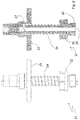
- Figure 1 is a side view (right) and a sectional view (left) of a first embodiment of a removal element 1 according to the invention.
- the removal element 1 has a base part 2 and a plate 3 which, relative to the base part 2, is between an advanced position, which is shown in FIG Figure 1 is shown and can be moved to a retracted position, not shown. With the aid of the spring element 4, the plate 3 is pressed into the advanced position.
- the base part 2 has a connection 5 with which the base part 2 can be connected to an aftertreatment plate (not shown).
- the removal element 1 has a fluid channel with a channel inlet 6 and a channel outlet 7. In the in the Figure 1 The situation shown can be supplied via the channel inlet 6 cooling fluid, which can escape via the various openings of the channel outlet 7.
- the base part 2 has a sleeve-shaped section with a conical edge surface 10.
- a valve body 8 is provided within the sleeve-shaped section and has correspondingly corresponding conical outer surfaces 9.
- a vacuum is now applied to the channel inlet 6 and if no hollow body molding is arranged on the plate 3, there is a large pressure difference between the channel inlet 6 and the channel outlet 7. This pressure difference ensures that the valve element 8 is in the Figure 1 is moved downward until the corresponding conical surfaces 9 and 10 lie on top of one another.
- the plate 3 is also moved slightly downwards, namely into its closed position. In the closed position, the valve passage is closed by the fluid channel.
- a bore 11 is provided in the base part 2, which creates a connection to the fluid channel.
- the bore 11 is closed both in the closed position and in the advanced position. If a hollow molded part now rests on the plate 3, this presses the plate 3 downwards, i.e. into its retracted position, whereby the valve passage is opened again via the bore 11 and a vacuum can be applied to the hollow molded part.
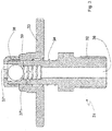
- FIG. 2 an alternative embodiment of the removal element 21 according to the invention is shown.
- the removal element 21 also has a base part 22.
- a plate 23 is provided which is movable relative to the base part 22 and, with the aid of the spring element 24, is moved into its advanced position, which is shown in FIG Figure 2 is shown, is pressed. In this position, a fluid channel with a channel inlet 26 and a channel outlet 27 is not closed, ie fluid can be supplied or removed via the fluid channel.
- the plate 23 will come into contact with the opening of the hollow body molding and the plate 23 will counteract the force of the spring element 24 downwards so that the channel outlet 27 is initially closed. In this embodiment, however, the plate 23 is pressed down so far that the opening of the channel outlet 27 is opened again, since the plate 23 is closer to the base part 22 than to the channel outlet 27. In this position, the molded hollow body can thus be evacuated.
- the plate 23 will only rest on the edge of the receiving cavity and will therefore not be pressed down as far as is the case if a hollow body molding is present.
- the distances are dimensioned in such a way that in this case the plate 23 is only pressed down so far that the channel outlet 27 is closed.
- the removal element 31 consists of a base part 32 and a plate 33, which can be moved relative to one another.
- the plate 33 With the aid of the spring element 34, the plate 33 is biased into the advanced position shown in FIG Figure 3 is shown.
- a fluid channel with a channel inlet 36 is also provided here.
- the channel outlet branches off and has two openings 37 'and 37 ".
- the opening 37" is closed in the position shown.
- the plate 33 With the aid of a molded hollow body part, the plate 33 can be moved downwards and the opening 37 "can be opened.
- the opening 37" which is closed or released by the plate 33, thus represents a shut-off valve.
- a check valve which has a valve ball 38 which is pressed into the position shown by means of the spring 39. In this position, cooling fluid can thus be supplied via the fluid channel and the channel outlet 37 '. If a vacuum is now applied to the channel inlet 36, this will result in the ball 38 moving downward against the spring force 39 due to the pressure difference and blocking the channel outlet 37 '. If there is no molded hollow body part, the channel is blocked. If, however, a hollow molded part is present, the plate 33 is pressed down in such a way that the channel outlet 37 ′′ is released and the hollow molded part can be evacuated via the fluid channel.
Landscapes
- Engineering & Computer Science (AREA)
- Manufacturing & Machinery (AREA)
- Mechanical Engineering (AREA)
- Robotics (AREA)
- Moulds For Moulding Plastics Or The Like (AREA)
- Injection Moulding Of Plastics Or The Like (AREA)
Claims (11)
- Élément d'extraction pour l'extraction d'une pièce moulée creuse, comprenant un espace intérieur de pièce moulée et une ouverture de pièce moulée, laquelle est délimitée par un bord de pièce moulée, depuis un outil de moulage par injection, l'élément d'extraction comportant un élément de base (2, 22, 32) et un plateau (3, 23, 33) qui est déplaçable entre une position avancée et une position rétractée par rapport à l'élément de base (2, 22, 32), un élément ressort (4, 24, 34) étant prévu, au moyen duquel le plateau (3, 23, 33) est poussé dans sa position avancée, le plateau (3, 23, 33) étant prévu pour entrer en contact avec le bord de la pièce moulée de façon à fermer l'ouverture de la pièce moulée et, par contact avec le bord de la pièce moulée, à être déplacé de la position avancée dans la position rétractée, un canal à fluide pourvu d'une entrée de canal (6, 26, 36) et d'une sortie de canal (7, 27, 37) étant prévu, l'entrée de canal (6, 26, 36) et la sortie de canal (7, 27 , 37) étant disposées de façon telle que, lorsque le plateau (3, 23, 33) se trouve dans la position rétractée, la sortie de canal (7, 27, 37) s'ouvre vers l'espace intérieur de la pièce moulée, si bien que, lorsque l'entrée de canal (6, 26, 36) est reliée à une source de vide, le fluide peut être aspiré de l'espace intérieur de la pièce moulée via le canal à fluide, un élément de soupape (8) pourvu d'un passage de soupape étant disposé entre l'entrée de canal (6, 26, 36) et la sortie de canal (7, 27, 37) ou sur le canal à fluide, la section du passage de soupape étant, dans une première position de soupape, plus grande que dans une seconde position de soupape,
caractérisé en ce que le passage de soupape dans la position avancée et dans la position rétractée du plateau (3, 23, 33) est ouvert, l'élément de soupape (8) étant dimensionné de telle sorte que dans la position avancée, lorsque la pression du fluide en entrée de canal (6, 26, 36) est plus faible qu'en sortie de canal (7, 27, 37), l'élément de soupape (8) se déplace dans la seconde position de soupape, tandis que dans la position rétractée, l'élément de soupape (8) se trouve toujours dans la première position de soupape. - Élément d'extraction pour l'extraction d'une pièce moulée creuse, comprenant un espace intérieur de pièce moulée et une ouverture de pièce moulée, laquelle est délimitée par un bord de pièce moulée, hors d'un outil de moulage par injection, l'élément d'extraction comportant un élément de base (2, 22, 32) et un plateau (3, 23, 33) qui est déplaçable entre une position avancée et une position rétractée par rapport à l'élément de base (2, 22, 32), un élément ressort (4, 24, 34) étant prévu, au moyen duquel le plateau (3, 23, 33) est poussé dans sa position avancée, le plateau (3, 23, 33) étant prévu pour entrer en contact avec le bord de la pièce moulée de façon à fermer l'ouverture de la pièce moulée et, par contact avec le bord de la pièce moulée, à être déplacé de la position avancée dans la position rétractée, un canal à fluide pourvu d'une entrée de canal (6, 26, 36) et d'une sortie de canal (7, 27, 37) étant prévu, l'entrée de canal (6, 26, 36) et la sortie de canal (7, 27 , 37) étant disposées de façon telle que, lorsque le plateau (3, 23, 33) se trouve dans la position rétractée, la sortie de canal (7, 27, 37) s'ouvre vers l'espace intérieur de la pièce moulée, de sorte que, lorsque l'entrée de canal (6, 26, 36) est reliée à une source de vide, du fluide peut être aspiré de l'espace intérieur de la pièce moulée via le canal à fluide, un élément de soupape (8) pourvu d'un passage de soupape étant disposé entre l'entrée de canal (6, 26, 36) et la sortie de canal (7, 27, 37) ou sur le canal à fluide, la section du passage de soupape étant, dans une première position de soupape, supérieure à celle dans une seconde position de soupape,
caractérisé en ce que le passage de soupape dans la position avancée et dans la position rétractée du plateau (3, 23, 33) est ouvert, le plateau (3, 23, 33) étant déplaçable en va-et-vient entre la position avancée, la position rétractée et une position de fermeture, l'élément de soupape (8) se trouvant, dans la position de fermeture du plateau (3, 23, 33), dans la seconde position de soupape. - Élément d'extraction selon la revendication 2, caractérisé en ce que la position de fermeture est disposée entre la position avancée et la position rétractée.
- Élément d'extraction selon l'une des revendications 1 à 3, caractérisé en ce que, dans la seconde position de soupape, le passage de soupape est fermé.
- Élément d'extraction selon l'une des revendications 1 à 4, caractérisé en ce que, dans une troisième position de soupape, la section du passage de soupape est plus petite que dans la première position de soupape et plus grande que dans la seconde position de soupape, l'élément de soupape (8) se trouvant, dans la position avancée du plateau (3, 23, 33), dans la troisième position de soupape lorsque la pression du fluide en entrée de canal (6, 26, 36) est supérieure ou égale à la pression du fluide en sortie de canal (7, 27, 37).
- Élément d'extraction selon l'une des revendications 1 à 5, caractérisé en ce que l'élément de soupape (8) comporte une soupape de retenue et une soupape d'arrêt, la soupape de retenue et la soupape d'arrêt étant disposées parallèlement l'une à l'autre, la soupape d'arrêt étant ouverte dans la position rétractée du plateau (3, 23, 33) et la soupape d'arrêt étant fermée dans la position avancée du plateau (3, 23, 33).
- Élément d'extraction selon la revendication 6, caractérisé en ce que la soupape de retenue est disposée de façon telle qu'elle se ferme lorsque la pression du fluide en entrée de canal (6, 26, 36) est plus faible qu'en sortie de canal (7, 27, 37).
- Plaque de post-traitement comprenant au moins un élément d'extraction selon l'une des revendications 1 à 7, caractérisée en ce que la partie de base (2, 22, 32) de l'élément de réception est reliée à la plaque de post-traitement de façon telle que, par l'intermédiaire de la plaque de post-traitement, du fluide peut être guidé via l'entrée de canal (6, 26, 36) dans le canal à fluide ou aspiré depuis celui-ci.
- Système de post-traitement de préformes creuses fabriquées par moulage par injection, comprenant(i) une plaque de réception qui présente au moins une cavité de réception destinée à recevoir une préforme,(ii) un système de post-traitement comprenant une plaque de post-traitement selon la revendication 8,(iii) un dispositif de déplacement permettant de déplacer en va-et-vient la plaque de réception par rapport à la plaque de post-traitement entre une position arrière et une position avant, la distance entre la plaque de réception et la plaque de post-traitement dans la position avant étant plus petite que dans la position arrière.
- Système selon la revendication 9, caractérisé en ce que la plaque de post-traitement présente au moins une broche de post-traitement pourvue d'un canal à fluide à travers lequel du fluide peut être introduit à l'intérieur d'une préforme reçue dans la cavité de réception ou être aspiré de celle-ci, auquel cas, dans la position avant, la broche de post-traitement est positionnée à l'intérieur de la cavité de réception et dans la position arrière, la broche de post-traitement n'est pas positionnée dans la cavité de réception.
- Système selon la revendication 9 ou 10, caractérisé en ce que dans la position avant, le plateau (3, 23, 33) repose au niveau d'une pièce moulée creuse logée dans la cavité de réception et l'élément de soupape (8) se trouve dans la première position de soupape ou, dans le cas où aucune pièce moulée creuse n'est positionnée dans la cavité de réception, il repose au niveau de la cavité de réception et l'élément de soupape (8) se trouve dans la seconde position de soupape.
Applications Claiming Priority (1)
| Application Number | Priority Date | Filing Date | Title |
|---|---|---|---|
| DE102018121878.8A DE102018121878A1 (de) | 2018-09-07 | 2018-09-07 | Entnahmeelement |
Publications (3)
| Publication Number | Publication Date |
|---|---|
| EP3620287A2 EP3620287A2 (fr) | 2020-03-11 |
| EP3620287A3 EP3620287A3 (fr) | 2020-04-01 |
| EP3620287B1 true EP3620287B1 (fr) | 2021-04-07 |
Family
ID=67850945
Family Applications (1)
| Application Number | Title | Priority Date | Filing Date |
|---|---|---|---|
| EP19195175.5A Active EP3620287B1 (fr) | 2018-09-07 | 2019-09-03 | Élément de réception |
Country Status (3)
| Country | Link |
|---|---|
| EP (1) | EP3620287B1 (fr) |
| CA (1) | CA3054416A1 (fr) |
| DE (1) | DE102018121878A1 (fr) |
Family Cites Families (5)
| Publication number | Priority date | Publication date | Assignee | Title |
|---|---|---|---|---|
| DE29716911U1 (de) * | 1997-09-20 | 1997-11-13 | Schmalz J Gmbh | Greifvorrichtung |
| US7670126B2 (en) * | 2006-05-12 | 2010-03-02 | Husky Injection Molding Systems Ltd. | Valve for controlling air flow in a molded article holder |
| US20080166209A1 (en) * | 2007-01-10 | 2008-07-10 | Husky Injection Molding Systems Ltd. | Molded Article Picker |
| US20130099420A1 (en) * | 2010-07-05 | 2013-04-25 | Gerry Ha | Picking tool |
| WO2016061682A1 (fr) * | 2014-10-21 | 2016-04-28 | Athena Automation Ltd. | Appareil et procédé de retenue post-moule |
-
2018
- 2018-09-07 DE DE102018121878.8A patent/DE102018121878A1/de active Pending
-
2019
- 2019-09-03 EP EP19195175.5A patent/EP3620287B1/fr active Active
- 2019-09-05 CA CA3054416A patent/CA3054416A1/fr active Pending
Non-Patent Citations (1)
| Title |
|---|
| None * |
Also Published As
| Publication number | Publication date |
|---|---|
| EP3620287A2 (fr) | 2020-03-11 |
| CA3054416A1 (fr) | 2020-03-07 |
| EP3620287A3 (fr) | 2020-04-01 |
| DE102018121878A1 (de) | 2020-03-12 |
Similar Documents
| Publication | Publication Date | Title |
|---|---|---|
| EP2358513B1 (fr) | Système de post-traitement et de transfert de préformes | |
| DE2640607B1 (de) | Verfahren und Form zum Kuehlen von Formlingen aus Kunststoff | |
| DE2615177A1 (de) | Arbeitsverfahren und vorrichtung zum herstellen von austriebfreien formteilen | |
| EP3186063B1 (fr) | Système de traitement ultérieur de préformes fabriquées par moulage par injection | |
| DE1679963C3 (de) | Vorrichtung zum Steuern der Öffnungsund Schließbewegung der Halsformteile und der Abstreifeinrichtung bei einer Spritzblasmaschine | |
| EP3651964A1 (fr) | Insert de noyau en plusieurs parties | |
| EP3620287B1 (fr) | Élément de réception | |
| DE10355018B4 (de) | Formnestaufbau | |
| WO2007063063A1 (fr) | Procede de post-traitement et dispositif approprie | |
| EP2825361A2 (fr) | Plaque outil de moulage par injection ainsi qu'outil de moulage par injection équipé d'une telle plaque | |
| DE102006028725A1 (de) | Verfahren und System zur Nachbehandlung von Vorformlingen | |
| DE102015112223A1 (de) | Spritzgießform mit Kernring | |
| DE102012021033A1 (de) | Spritzgießmaschine | |
| DE10355300A1 (de) | Verfahren zum Spritzgießen von Kunststoffmaterialien unter Verwendung von Gashaltedruck in der Form | |
| DE102016102616A1 (de) | Spritzgießform mit integrierten Luftdüsen | |
| DE102016112102A1 (de) | Formeinrichtung für ein Thermoformwerkzeug | |
| DE4041799A1 (de) | Verfahren zum spritzgiessen von sandwichteilen und vorrichtung zur durchfuehrung des verfahrens | |
| EP2029346B1 (fr) | Dispositif de positionnement | |
| DE2103885B2 (de) | Verfahren und Vorrichtung zur Herstellung von Spritzgußgegenständen aus zwei unterschiedlichen Kunststoffmaterialien | |
| DE102022127266A1 (de) | Füllkörper für ein Formwerkzeug | |
| DE102022110443A1 (de) | Vorrichtung zum Mikrospritzgießen | |
| DE102007049746A1 (de) | Auswurfvorrichtung mit Stoppelement | |
| DE102012208137A1 (de) | Thermoformwerkzeug zur Herstellung von becherförmigen Gegenständen aus einer erwärmten Kunststofffolie | |
| DE2640607C3 (fr) | ||
| DE102007053668A1 (de) | Auswurfvorrichtung mit Stoppelement |
Legal Events
| Date | Code | Title | Description |
|---|---|---|---|
| PUAI | Public reference made under article 153(3) epc to a published international application that has entered the european phase |
Free format text: ORIGINAL CODE: 0009012 |
|
| STAA | Information on the status of an ep patent application or granted ep patent |
Free format text: STATUS: THE APPLICATION HAS BEEN PUBLISHED |
|
| PUAL | Search report despatched |
Free format text: ORIGINAL CODE: 0009013 |
|
| AK | Designated contracting states |
Kind code of ref document: A2 Designated state(s): AL AT BE BG CH CY CZ DE DK EE ES FI FR GB GR HR HU IE IS IT LI LT LU LV MC MK MT NL NO PL PT RO RS SE SI SK SM TR |
|
| AX | Request for extension of the european patent |
Extension state: BA ME |
|
| AK | Designated contracting states |
Kind code of ref document: A3 Designated state(s): AL AT BE BG CH CY CZ DE DK EE ES FI FR GB GR HR HU IE IS IT LI LT LU LV MC MK MT NL NO PL PT RO RS SE SI SK SM TR |
|
| AX | Request for extension of the european patent |
Extension state: BA ME |
|
| RIC1 | Information provided on ipc code assigned before grant |
Ipc: B29C 45/72 20060101ALI20200222BHEP Ipc: B29K 105/00 20060101ALN20200222BHEP Ipc: B29C 49/64 20060101ALI20200222BHEP Ipc: B29C 45/42 20060101AFI20200222BHEP |
|
| STAA | Information on the status of an ep patent application or granted ep patent |
Free format text: STATUS: REQUEST FOR EXAMINATION WAS MADE |
|
| 17P | Request for examination filed |
Effective date: 20200928 |
|
| RBV | Designated contracting states (corrected) |
Designated state(s): AL AT BE BG CH CY CZ DE DK EE ES FI FR GB GR HR HU IE IS IT LI LT LU LV MC MK MT NL NO PL PT RO RS SE SI SK SM TR |
|
| GRAP | Despatch of communication of intention to grant a patent |
Free format text: ORIGINAL CODE: EPIDOSNIGR1 |
|
| STAA | Information on the status of an ep patent application or granted ep patent |
Free format text: STATUS: GRANT OF PATENT IS INTENDED |
|
| RIC1 | Information provided on ipc code assigned before grant |
Ipc: B29C 45/42 20060101AFI20201124BHEP Ipc: B29K 105/00 20060101ALN20201124BHEP Ipc: B29C 49/64 20060101ALI20201124BHEP Ipc: B29C 45/72 20060101ALI20201124BHEP |
|
| INTG | Intention to grant announced |
Effective date: 20201209 |
|
| GRAS | Grant fee paid |
Free format text: ORIGINAL CODE: EPIDOSNIGR3 |
|
| GRAA | (expected) grant |
Free format text: ORIGINAL CODE: 0009210 |
|
| STAA | Information on the status of an ep patent application or granted ep patent |
Free format text: STATUS: THE PATENT HAS BEEN GRANTED |
|
| AK | Designated contracting states |
Kind code of ref document: B1 Designated state(s): AL AT BE BG CH CY CZ DE DK EE ES FI FR GB GR HR HU IE IS IT LI LT LU LV MC MK MT NL NO PL PT RO RS SE SI SK SM TR |
|
| REG | Reference to a national code |
Ref country code: GB Ref legal event code: FG4D Free format text: NOT ENGLISH |
|
| REG | Reference to a national code |
Ref country code: AT Ref legal event code: REF Ref document number: 1379095 Country of ref document: AT Kind code of ref document: T Effective date: 20210415 Ref country code: CH Ref legal event code: EP |
|
| REG | Reference to a national code |
Ref country code: DE Ref legal event code: R096 Ref document number: 502019001175 Country of ref document: DE |
|
| REG | Reference to a national code |
Ref country code: IE Ref legal event code: FG4D Free format text: LANGUAGE OF EP DOCUMENT: GERMAN |
|
| REG | Reference to a national code |
Ref country code: LT Ref legal event code: MG9D |
|
| REG | Reference to a national code |
Ref country code: NL Ref legal event code: MP Effective date: 20210407 |
|
| PG25 | Lapsed in a contracting state [announced via postgrant information from national office to epo] |
Ref country code: LT Free format text: LAPSE BECAUSE OF FAILURE TO SUBMIT A TRANSLATION OF THE DESCRIPTION OR TO PAY THE FEE WITHIN THE PRESCRIBED TIME-LIMIT Effective date: 20210407 Ref country code: HR Free format text: LAPSE BECAUSE OF FAILURE TO SUBMIT A TRANSLATION OF THE DESCRIPTION OR TO PAY THE FEE WITHIN THE PRESCRIBED TIME-LIMIT Effective date: 20210407 Ref country code: FI Free format text: LAPSE BECAUSE OF FAILURE TO SUBMIT A TRANSLATION OF THE DESCRIPTION OR TO PAY THE FEE WITHIN THE PRESCRIBED TIME-LIMIT Effective date: 20210407 Ref country code: NL Free format text: LAPSE BECAUSE OF FAILURE TO SUBMIT A TRANSLATION OF THE DESCRIPTION OR TO PAY THE FEE WITHIN THE PRESCRIBED TIME-LIMIT Effective date: 20210407 Ref country code: BG Free format text: LAPSE BECAUSE OF FAILURE TO SUBMIT A TRANSLATION OF THE DESCRIPTION OR TO PAY THE FEE WITHIN THE PRESCRIBED TIME-LIMIT Effective date: 20210707 |
|
| PG25 | Lapsed in a contracting state [announced via postgrant information from national office to epo] |
Ref country code: RS Free format text: LAPSE BECAUSE OF FAILURE TO SUBMIT A TRANSLATION OF THE DESCRIPTION OR TO PAY THE FEE WITHIN THE PRESCRIBED TIME-LIMIT Effective date: 20210407 Ref country code: PT Free format text: LAPSE BECAUSE OF FAILURE TO SUBMIT A TRANSLATION OF THE DESCRIPTION OR TO PAY THE FEE WITHIN THE PRESCRIBED TIME-LIMIT Effective date: 20210809 Ref country code: SE Free format text: LAPSE BECAUSE OF FAILURE TO SUBMIT A TRANSLATION OF THE DESCRIPTION OR TO PAY THE FEE WITHIN THE PRESCRIBED TIME-LIMIT Effective date: 20210407 Ref country code: LV Free format text: LAPSE BECAUSE OF FAILURE TO SUBMIT A TRANSLATION OF THE DESCRIPTION OR TO PAY THE FEE WITHIN THE PRESCRIBED TIME-LIMIT Effective date: 20210407 Ref country code: PL Free format text: LAPSE BECAUSE OF FAILURE TO SUBMIT A TRANSLATION OF THE DESCRIPTION OR TO PAY THE FEE WITHIN THE PRESCRIBED TIME-LIMIT Effective date: 20210407 Ref country code: NO Free format text: LAPSE BECAUSE OF FAILURE TO SUBMIT A TRANSLATION OF THE DESCRIPTION OR TO PAY THE FEE WITHIN THE PRESCRIBED TIME-LIMIT Effective date: 20210707 Ref country code: IS Free format text: LAPSE BECAUSE OF FAILURE TO SUBMIT A TRANSLATION OF THE DESCRIPTION OR TO PAY THE FEE WITHIN THE PRESCRIBED TIME-LIMIT Effective date: 20210807 Ref country code: GR Free format text: LAPSE BECAUSE OF FAILURE TO SUBMIT A TRANSLATION OF THE DESCRIPTION OR TO PAY THE FEE WITHIN THE PRESCRIBED TIME-LIMIT Effective date: 20210708 |
|
| REG | Reference to a national code |
Ref country code: DE Ref legal event code: R097 Ref document number: 502019001175 Country of ref document: DE |
|
| PG25 | Lapsed in a contracting state [announced via postgrant information from national office to epo] |
Ref country code: SK Free format text: LAPSE BECAUSE OF FAILURE TO SUBMIT A TRANSLATION OF THE DESCRIPTION OR TO PAY THE FEE WITHIN THE PRESCRIBED TIME-LIMIT Effective date: 20210407 Ref country code: ES Free format text: LAPSE BECAUSE OF FAILURE TO SUBMIT A TRANSLATION OF THE DESCRIPTION OR TO PAY THE FEE WITHIN THE PRESCRIBED TIME-LIMIT Effective date: 20210407 Ref country code: EE Free format text: LAPSE BECAUSE OF FAILURE TO SUBMIT A TRANSLATION OF THE DESCRIPTION OR TO PAY THE FEE WITHIN THE PRESCRIBED TIME-LIMIT Effective date: 20210407 Ref country code: RO Free format text: LAPSE BECAUSE OF FAILURE TO SUBMIT A TRANSLATION OF THE DESCRIPTION OR TO PAY THE FEE WITHIN THE PRESCRIBED TIME-LIMIT Effective date: 20210407 Ref country code: SM Free format text: LAPSE BECAUSE OF FAILURE TO SUBMIT A TRANSLATION OF THE DESCRIPTION OR TO PAY THE FEE WITHIN THE PRESCRIBED TIME-LIMIT Effective date: 20210407 Ref country code: CZ Free format text: LAPSE BECAUSE OF FAILURE TO SUBMIT A TRANSLATION OF THE DESCRIPTION OR TO PAY THE FEE WITHIN THE PRESCRIBED TIME-LIMIT Effective date: 20210407 Ref country code: DK Free format text: LAPSE BECAUSE OF FAILURE TO SUBMIT A TRANSLATION OF THE DESCRIPTION OR TO PAY THE FEE WITHIN THE PRESCRIBED TIME-LIMIT Effective date: 20210407 |
|
| PLBE | No opposition filed within time limit |
Free format text: ORIGINAL CODE: 0009261 |
|
| STAA | Information on the status of an ep patent application or granted ep patent |
Free format text: STATUS: NO OPPOSITION FILED WITHIN TIME LIMIT |
|
| 26N | No opposition filed |
Effective date: 20220110 |
|
| REG | Reference to a national code |
Ref country code: BE Ref legal event code: MM Effective date: 20210930 |
|
| PG25 | Lapsed in a contracting state [announced via postgrant information from national office to epo] |
Ref country code: IS Free format text: LAPSE BECAUSE OF FAILURE TO SUBMIT A TRANSLATION OF THE DESCRIPTION OR TO PAY THE FEE WITHIN THE PRESCRIBED TIME-LIMIT Effective date: 20210807 Ref country code: MC Free format text: LAPSE BECAUSE OF FAILURE TO SUBMIT A TRANSLATION OF THE DESCRIPTION OR TO PAY THE FEE WITHIN THE PRESCRIBED TIME-LIMIT Effective date: 20210407 Ref country code: AL Free format text: LAPSE BECAUSE OF FAILURE TO SUBMIT A TRANSLATION OF THE DESCRIPTION OR TO PAY THE FEE WITHIN THE PRESCRIBED TIME-LIMIT Effective date: 20210407 |
|
| PG25 | Lapsed in a contracting state [announced via postgrant information from national office to epo] |
Ref country code: IE Free format text: LAPSE BECAUSE OF NON-PAYMENT OF DUE FEES Effective date: 20210903 Ref country code: FR Free format text: LAPSE BECAUSE OF NON-PAYMENT OF DUE FEES Effective date: 20210930 Ref country code: BE Free format text: LAPSE BECAUSE OF NON-PAYMENT OF DUE FEES Effective date: 20210930 |
|
| PG25 | Lapsed in a contracting state [announced via postgrant information from national office to epo] |
Ref country code: CY Free format text: LAPSE BECAUSE OF FAILURE TO SUBMIT A TRANSLATION OF THE DESCRIPTION OR TO PAY THE FEE WITHIN THE PRESCRIBED TIME-LIMIT Effective date: 20210407 |
|
| PG25 | Lapsed in a contracting state [announced via postgrant information from national office to epo] |
Ref country code: HU Free format text: LAPSE BECAUSE OF FAILURE TO SUBMIT A TRANSLATION OF THE DESCRIPTION OR TO PAY THE FEE WITHIN THE PRESCRIBED TIME-LIMIT; INVALID AB INITIO Effective date: 20190903 |
|
| PGFP | Annual fee paid to national office [announced via postgrant information from national office to epo] |
Ref country code: LU Payment date: 20230921 Year of fee payment: 5 |
|
| PGFP | Annual fee paid to national office [announced via postgrant information from national office to epo] |
Ref country code: DE Payment date: 20230919 Year of fee payment: 5 |
|
| PGFP | Annual fee paid to national office [announced via postgrant information from national office to epo] |
Ref country code: IT Payment date: 20230927 Year of fee payment: 5 Ref country code: CH Payment date: 20231001 Year of fee payment: 5 |
|
| PG25 | Lapsed in a contracting state [announced via postgrant information from national office to epo] |
Ref country code: MK Free format text: LAPSE BECAUSE OF FAILURE TO SUBMIT A TRANSLATION OF THE DESCRIPTION OR TO PAY THE FEE WITHIN THE PRESCRIBED TIME-LIMIT Effective date: 20210407 |