EP3620287B1 - Removal element - Google Patents
Removal element Download PDFInfo
- Publication number
- EP3620287B1 EP3620287B1 EP19195175.5A EP19195175A EP3620287B1 EP 3620287 B1 EP3620287 B1 EP 3620287B1 EP 19195175 A EP19195175 A EP 19195175A EP 3620287 B1 EP3620287 B1 EP 3620287B1
- Authority
- EP
- European Patent Office
- Prior art keywords
- valve
- plate
- runner
- moulded article
- fluid
- Prior art date
- Legal status (The legal status is an assumption and is not a legal conclusion. Google has not performed a legal analysis and makes no representation as to the accuracy of the status listed.)
- Active
Links
- 239000012530 fluid Substances 0.000 claims description 44
- 238000000465 moulding Methods 0.000 claims description 34
- 238000001746 injection moulding Methods 0.000 claims description 18
- 238000007789 sealing Methods 0.000 claims 2
- 239000012809 cooling fluid Substances 0.000 description 6
- 238000000605 extraction Methods 0.000 description 6
- 238000002347 injection Methods 0.000 description 5
- 239000007924 injection Substances 0.000 description 5
- 239000003570 air Substances 0.000 description 4
- 238000000071 blow moulding Methods 0.000 description 2
- 150000001875 compounds Chemical class 0.000 description 2
- 238000004519 manufacturing process Methods 0.000 description 2
- 238000000034 method Methods 0.000 description 2
- 239000012080 ambient air Substances 0.000 description 1
- 230000000903 blocking effect Effects 0.000 description 1
- 238000001816 cooling Methods 0.000 description 1
- 238000005553 drilling Methods 0.000 description 1
- 230000000694 effects Effects 0.000 description 1
- 210000003746 feather Anatomy 0.000 description 1
- 239000008187 granular material Substances 0.000 description 1
- 230000005484 gravity Effects 0.000 description 1
- 239000000843 powder Substances 0.000 description 1
- 239000007787 solid Substances 0.000 description 1
Images

Classifications
-
- B—PERFORMING OPERATIONS; TRANSPORTING
- B29—WORKING OF PLASTICS; WORKING OF SUBSTANCES IN A PLASTIC STATE IN GENERAL
- B29C—SHAPING OR JOINING OF PLASTICS; SHAPING OF MATERIAL IN A PLASTIC STATE, NOT OTHERWISE PROVIDED FOR; AFTER-TREATMENT OF THE SHAPED PRODUCTS, e.g. REPAIRING
- B29C45/00—Injection moulding, i.e. forcing the required volume of moulding material through a nozzle into a closed mould; Apparatus therefor
- B29C45/17—Component parts, details or accessories; Auxiliary operations
- B29C45/40—Removing or ejecting moulded articles
- B29C45/42—Removing or ejecting moulded articles using means movable from outside the mould between mould parts, e.g. robots
- B29C45/4225—Take-off members or carriers for the moulded articles, e.g. grippers
-
- B—PERFORMING OPERATIONS; TRANSPORTING
- B29—WORKING OF PLASTICS; WORKING OF SUBSTANCES IN A PLASTIC STATE IN GENERAL
- B29C—SHAPING OR JOINING OF PLASTICS; SHAPING OF MATERIAL IN A PLASTIC STATE, NOT OTHERWISE PROVIDED FOR; AFTER-TREATMENT OF THE SHAPED PRODUCTS, e.g. REPAIRING
- B29C45/00—Injection moulding, i.e. forcing the required volume of moulding material through a nozzle into a closed mould; Apparatus therefor
- B29C45/17—Component parts, details or accessories; Auxiliary operations
- B29C45/72—Heating or cooling
- B29C45/7207—Heating or cooling of the moulded articles
- B29C2045/7214—Preform carriers for cooling preforms
-
- B—PERFORMING OPERATIONS; TRANSPORTING
- B29—WORKING OF PLASTICS; WORKING OF SUBSTANCES IN A PLASTIC STATE IN GENERAL
- B29K—INDEXING SCHEME ASSOCIATED WITH SUBCLASSES B29B, B29C OR B29D, RELATING TO MOULDING MATERIALS OR TO MATERIALS FOR MOULDS, REINFORCEMENTS, FILLERS OR PREFORMED PARTS, e.g. INSERTS
- B29K2105/00—Condition, form or state of moulded material or of the material to be shaped
- B29K2105/25—Solid
- B29K2105/253—Preform
Definitions
- the present invention relates to a removal element for removing a molded hollow body part from an injection molding tool.
- the hollow molded part has a molded part interior and a molded part opening which is delimited by a molded part edge.
- the present invention also relates to an aftertreatment plate and an aftertreatment system with such a removal element.
- Injection molding is one of the most important processes for producing moldings or molded parts.
- the molding compound which is generally originally in the form of a powder or granulate, is heated, plasticized and pressed into a corresponding molding tool under high pressure. The molding compound solidifies in the molding tool and is then removed from the open tool as a molded part.
- An example of a molding is a hollow body preform for the production of PET bottles.
- the present invention is explained using the example of such a hollow body preform. In principle, however, it can also be used with other molded parts.
- PET bottles are generally produced by stretch blow molding a hollow body parison.
- the hollow body preform is created by means of injection molding.
- the stretch blow molding that follows the injection molding process can take place either immediately after the hollow body preform has been produced or at a later point in time.
- An injection molding tool for producing PET preforms usually consists of a large number, for example 96, cavities into which correspondingly designed tool cores are inserted.
- a space the so-called mold space
- the plasticized plastic for example PET
- the mold is then under high Pressure injected.
- the preform is generally transferred to a so-called receiving plate, which consists of a group of receiving cavities.
- receiving plates which have several groups of receiving cavities, each group having as many receiving cavities as the injection mold provides preforms per injection cycle. The individual groups of receiving cavities are then fitted with preforms one after the other, so that the individual preform can remain in the receiving cavity for longer than one injection molding cycle.
- the post-treatment pens are on a post-treatment plate arranged, which can be displaced relative to the receiving plate with the receiving cavities, wherein the post-treatment pins are arranged within the preforms in one position, while this is not the case in the other position.
- the aftertreatment plate usually also has the removal elements mentioned at the outset, the molded parts being removed from a group of receiving cavities with the aid of the removal elements, while the post-treatment pins hold the preform in the other groups of receiving cavities post-treatment. With the removal elements, the molded parts are therefore always removed from the group of receiving cavities which have been held in the receiving cavities for the longest. Cooling from the inside takes place exclusively via the post-treatment pins, i.e. there is no post-treatment from the inside during the removal process. Either fluid, e.g. cool air, can be supplied via the extraction pins, so that warm air is displaced from the hollow body molding and replaced by the cooler one, or fluid, e.g. warm air, is sucked out of the hollow body molding through the extraction pins, so that cooler Air flows in from the environment. In both cases, the hollow body molding is cooled more effectively from the inside.
- fluid e.g. cool air
- the removal element has a base part and a plate which can be moved between an advanced position and a retracted position relative to the base part.
- a spring element is provided with which the plate is pressed into its advanced position, the plate being intended to come into contact with the molding edge in such a way that it closes the molding opening and, through contact with the molding opening, from the advanced position in the retracted position is moved.
- the removal element also has a fluid channel with a channel inlet and a channel outlet which are arranged such that when the plate is in the retracted position, the channel outlet opens to the interior of the molded part, so that when the channel inlet is connected to a vacuum source, Fluid can be sucked out of the interior of the molded part via the fluid channel. Since the plate closes the hollow body molding, a vacuum is thus formed within the hollow body and the hollow body molding is drawn onto the plate and can be moved away from the receiving cavity together with it in order to remove the hollow body molding from the injection molding tool.
- An injection molding tool is understood to mean all parts of the injection molding tool, ie not only the cavity forming the mold space, but also the downstream receiving cavity in which the post-treatment of the hollow molded part takes place.
- the receiving cavity does not contain any molded part because, for example, the associated cavity forming the mold space is damaged.
- this has the consequence that when the channel inlet is connected to a vacuum, no negative pressure is formed in a molded part and instead ambient air is sucked into the channel outlet unhindered. Since, as a rule, a large number of receiving cavities are arranged next to one another and therefore a large number of extraction elements are also connected to a common vacuum connection, this in turn means that the negative pressure in the extraction elements, which is located next to the extraction element, which is not closed by a hollow body molding are not sufficient to remove the molded part from the receiving cavity.
- valve passage is closed in the second valve position. It is therefore assumed in the following description that the valve passage is closed in the second valve position. In principle, however, it would also be possible in the second valve position merely to throttle the valve passage significantly, which even then reduces the negative effects on adjacent extraction elements in the event that no hollow body molding is present.
- valve passage in the retracted position of the plate is necessary in order to apply a vacuum via the fluid channel in order to be able to remove the molded part.
- valve passage is also open in the advanced position, so that fluid can be supplied or discharged via the fluid channel, post-treatment can also take place via the removal element from the inside.
- the post-treatment time for post-treatment of the interior of the hollow body molding is increased by almost 50%.
- the plate can be moved back and forth between the advanced position, the retracted position and a closed position, the valve element being in the second valve position in the closed position of the plate.
- the plate has a total of three positions, namely the advanced position, the retracted position and a locking position. Only in the closed position is the valve element closed or the valve passage strongly throttled. In contrast, the valve passage is open both in the advanced position and in the retracted position.
- the locking position can be arranged between the advanced position and the retracted position. This means that when a vacuum is applied to the channel entrance, the plate moves from the advanced position in the direction of the retracted position to the closed position. This can be achieved, for example, by means of corresponding control surfaces that are subjected to pressure. However, it is not necessary for the locking position to be located between the advanced position and the retracted position. Thus, the closed position can also be arranged further away from the retracted position than the advanced position.
- the cross section of the valve passage in a third valve position is smaller than in the first valve position and larger than in the second valve position, wherein in the advanced position of the plate the valve element is in the third valve position when the fluid pressure at the channel inlet is greater or greater is equal to the fluid pressure at the channel outlet.
- valve element has a check valve and a check valve, the check valve and the check valve being arranged parallel to one another so that the check valve is opened in the retracted position of the plate and the check valve is closed in the advanced position of the plate .
- the check valve can be arranged such that it closes when the fluid pressure at the channel inlet is lower than at the channel outlet.
- Cooling fluid can thus be fed into the hollow body molding via the check valve. If the channel inlet is connected to a vacuum, the check valve closes. Only when the shut-off valve is open, i.e. the plate is in its retracted position, can the molded hollow body be evacuated via the shut-off valve. In this embodiment, both the supply of cooling fluid and the evacuation take place via the same fluid channel.
- the present invention relates to an aftertreatment plate with at least one removal element as described above, the base part of the removal element being connected to the aftertreatment plate in such a way that fluid can be fed into or sucked out of the fluid channel via the aftertreatment plate via the channel inlet.
- the receiving plate For post-treatment or removal of the hollow body moldings, the receiving plate is thus brought into the front position with the aid of the movement device. In this position, the removal element is in contact with the molded hollow body part, so that the plate is moved into the retracted position and the molded hollow body can be evacuated via the removal element.
- the receiving plate can then be brought into the rear position so that the molded hollow body is removed from the receiving cavity. It is both possible to move the aftertreatment plate relative to a standing receiving plate and it is also possible to move the receiving plate relative to a standing aftertreatment plate.
- the aftertreatment plate can have at least one aftertreatment pin with a fluid channel through which fluid enters the interior of a Receiving cavity received molding can be introduced or sucked out therefrom, wherein in the front position the post-treatment pin is positioned within the receiving cavity and in the rear position of the post-treatment pin is not positioned within the receiving cavity.
- the aftertreatment pin and the removal element can be constructed in a similar manner, with the difference that the aftertreatment pin has no valve element and no movable plate.
- the plate in the front position, the plate either rests against a molded hollow body part received in the receiving cavity and the valve is in the first valve position, or, if no molded hollow body part is positioned in the receiving cavity, rests against the receiving cavity and that Valve is in the second valve position.
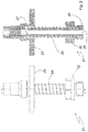
- Figure 1 is a side view (right) and a sectional view (left) of a first embodiment of a removal element 1 according to the invention.
- the removal element 1 has a base part 2 and a plate 3 which, relative to the base part 2, is between an advanced position, which is shown in FIG Figure 1 is shown and can be moved to a retracted position, not shown. With the aid of the spring element 4, the plate 3 is pressed into the advanced position.
- the base part 2 has a connection 5 with which the base part 2 can be connected to an aftertreatment plate (not shown).
- the removal element 1 has a fluid channel with a channel inlet 6 and a channel outlet 7. In the in the Figure 1 The situation shown can be supplied via the channel inlet 6 cooling fluid, which can escape via the various openings of the channel outlet 7.
- the base part 2 has a sleeve-shaped section with a conical edge surface 10.
- a valve body 8 is provided within the sleeve-shaped section and has correspondingly corresponding conical outer surfaces 9.
- a vacuum is now applied to the channel inlet 6 and if no hollow body molding is arranged on the plate 3, there is a large pressure difference between the channel inlet 6 and the channel outlet 7. This pressure difference ensures that the valve element 8 is in the Figure 1 is moved downward until the corresponding conical surfaces 9 and 10 lie on top of one another.
- the plate 3 is also moved slightly downwards, namely into its closed position. In the closed position, the valve passage is closed by the fluid channel.
- a bore 11 is provided in the base part 2, which creates a connection to the fluid channel.
- the bore 11 is closed both in the closed position and in the advanced position. If a hollow molded part now rests on the plate 3, this presses the plate 3 downwards, i.e. into its retracted position, whereby the valve passage is opened again via the bore 11 and a vacuum can be applied to the hollow molded part.
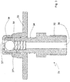
- FIG. 2 an alternative embodiment of the removal element 21 according to the invention is shown.
- the removal element 21 also has a base part 22.
- a plate 23 is provided which is movable relative to the base part 22 and, with the aid of the spring element 24, is moved into its advanced position, which is shown in FIG Figure 2 is shown, is pressed. In this position, a fluid channel with a channel inlet 26 and a channel outlet 27 is not closed, ie fluid can be supplied or removed via the fluid channel.
- the plate 23 will come into contact with the opening of the hollow body molding and the plate 23 will counteract the force of the spring element 24 downwards so that the channel outlet 27 is initially closed. In this embodiment, however, the plate 23 is pressed down so far that the opening of the channel outlet 27 is opened again, since the plate 23 is closer to the base part 22 than to the channel outlet 27. In this position, the molded hollow body can thus be evacuated.
- the plate 23 will only rest on the edge of the receiving cavity and will therefore not be pressed down as far as is the case if a hollow body molding is present.
- the distances are dimensioned in such a way that in this case the plate 23 is only pressed down so far that the channel outlet 27 is closed.
- the removal element 31 consists of a base part 32 and a plate 33, which can be moved relative to one another.
- the plate 33 With the aid of the spring element 34, the plate 33 is biased into the advanced position shown in FIG Figure 3 is shown.
- a fluid channel with a channel inlet 36 is also provided here.
- the channel outlet branches off and has two openings 37 'and 37 ".
- the opening 37" is closed in the position shown.
- the plate 33 With the aid of a molded hollow body part, the plate 33 can be moved downwards and the opening 37 "can be opened.
- the opening 37" which is closed or released by the plate 33, thus represents a shut-off valve.
- a check valve which has a valve ball 38 which is pressed into the position shown by means of the spring 39. In this position, cooling fluid can thus be supplied via the fluid channel and the channel outlet 37 '. If a vacuum is now applied to the channel inlet 36, this will result in the ball 38 moving downward against the spring force 39 due to the pressure difference and blocking the channel outlet 37 '. If there is no molded hollow body part, the channel is blocked. If, however, a hollow molded part is present, the plate 33 is pressed down in such a way that the channel outlet 37 ′′ is released and the hollow molded part can be evacuated via the fluid channel.
Description
Die vorliegende Erfindung betrifft ein Entnahmeelement für die Entnahme eines Hohlkörperformteils aus einem Spritzgießwerkzeug. Das Hohlkörperformteil weist einen Formteilinnenraum und eine Formteilöffnung auf, welche von einem Formteilrand begrenzt wird. Des Weiteren betrifft die vorliegende Erfindung eine Nachbehandlungsplatte sowie ein Nachbehandlungssystem mit einem solchen Entnahmeelement.The present invention relates to a removal element for removing a molded hollow body part from an injection molding tool. The hollow molded part has a molded part interior and a molded part opening which is delimited by a molded part edge. The present invention also relates to an aftertreatment plate and an aftertreatment system with such a removal element.
Das Spritzgießen ist eines der wichtigsten Verfahren zur Herstellung von Formlingen bzw. Formteilen. Hierbei wird die im Allgemeinen ursprünglich als Pulver oder Granulat vorliegende Formmasse erhitzt, plastifiziert und unter hohem Druck in ein entsprechendes Formwerkzeug gedrückt. Die Formmasse erstarrt in dem Formwerkzeug und wird anschließend als Formteil dem geöffneten Werkzeug entnommen.Injection molding is one of the most important processes for producing moldings or molded parts. Here, the molding compound, which is generally originally in the form of a powder or granulate, is heated, plasticized and pressed into a corresponding molding tool under high pressure. The molding compound solidifies in the molding tool and is then removed from the open tool as a molded part.
Ein Beispiel eines Formlings ist ein Hohlkörpervorformling zur Herstellung von PET-Flaschen. Die vorliegende Erfindung wird am Beispiel eines solchen Hohlkörpervorformlings erläutert. Sie kann aber prinzipiell auch mit anderen Formteilen verwendet werden.An example of a molding is a hollow body preform for the production of PET bottles. The present invention is explained using the example of such a hollow body preform. In principle, however, it can also be used with other molded parts.
Handelsübliche PET-Flaschen werden im Allgemeinen durch Streckblasformen eines Hohlkörpervorformlings hergestellt. Dabei wird der Hohlkörpervorformling in einem ersten Schritt mittels Spritzgießen erstellt. Das sich an den Spritzgießvorgang anschließende Streckblasformen kann entweder unmittelbar nach Herstellung des Hohlkörpervorformlings oder zu einem späteren Zeitpunkt erfolgen.Commercially available PET bottles are generally produced by stretch blow molding a hollow body parison. In the first step, the hollow body preform is created by means of injection molding. The stretch blow molding that follows the injection molding process can take place either immediately after the hollow body preform has been produced or at a later point in time.
Bei der Herstellung der entsprechenden Spritzgießformen ist ein hoher Aufwand vonnöten, da die Spritzgießform einerseits für sehr hohe Drücke ausgelegt sein muss und andererseits auch entsprechend beheizte und/oder gekühlte Kanäle aufweisen muss.The production of the corresponding injection molds requires great effort, since the injection mold must on the one hand be designed for very high pressures and on the other hand must also have appropriately heated and / or cooled channels.
Üblicherweise besteht ein Spritzgießwerkzeug zur Herstellung von PET-Vorformlingen aus einer Vielzahl, z.B. 96, Kavitäten, in die entsprechend ausgebildete Werkzeugkerne eingeführt werden. Bei geschlossenem Werkzeug, d.h., wenn der Kern in die entsprechende Kavität eingesetzt ist, wird zwischen dem Kern einerseits und der Kavität andererseits ein Raum, der sogenannte Formraum, gebildet. In diesem Raum wird dann der plastifizierte Kunststoff, z.B. PET, unter hohem Druck eingespritzt. Sobald der PET-Vorformling genügend abgekühlt ist, kann die Form geöffnet und der Vorformling entnommen werden.An injection molding tool for producing PET preforms usually consists of a large number, for example 96, cavities into which correspondingly designed tool cores are inserted. When the tool is closed, ie when the core is inserted into the corresponding cavity, a space, the so-called mold space, is formed between the core on the one hand and the cavity on the other hand. In this space the plasticized plastic, for example PET, is then under high Pressure injected. As soon as the PET preform has cooled down sufficiently, the mold can be opened and the preform removed.
Um die Zykluszeiten, d.h. die Zeit von einem Spritzgießvorgang bis zu dem nächsten Spritzgießvorgang, zu reduzieren, ist es bereits üblich, den Vorformling zu einem sehr frühen Zeitpunkt aus der Form zu entnehmen, zu dem der Vorformling an seinen Außenflächen bereits fest ist, dessen innerer Bereich jedoch noch flüssig ist. In diesem Zustand wird der Vorformling im Allgemeinen einer sogenannten Aufnahmeplatte übergeben, die aus einer Gruppe von Aufnahmekavitäten besteht. So ist es beispielsweise bei den sogenannten Vertikalwerkzeugen, d.h. denjenigen Spritzgießwerkzeugen, die sich durch eine vertikale Bewegung des einen Werkzeugteils gegenüber dem anderen öffnen, üblich, die Werkzeugform bereits nach z.B. zehn Sekunden zu öffnen, eine Aufnahmeplatte mit entsprechenden Aufnahmekavitäten in die Form einzufahren, die einzelnen Preforms in die Aufnahmekavitäten mittels Schwerkraft hineinfallen zu lassen, die Aufnahmeplatte mit den Vorformlingen aus dem Werkzeug herauszufahren, die Form wieder zu schließen und den nächsten Spritzgießvorgang zu beginnen. Während des nächsten Spritzgießvorgangs verbleiben die vorherigen Preforms in der Aufnahmekavität, die üblicherweise gekühlt wird. Es sind auch Ausführungsformen bekannt, bei denen die einzelnen Vorformlinge mittels einer Greifereinheit aus der Form entnommen und in die außerhalb der Werkzeugform angeordnete Aufnahmeplatte übergeben werden.In order to reduce the cycle times, ie the time from one injection molding to the next, it is already common practice to remove the preform from the mold at a very early point in time when the preform is already solid on its outer surfaces, its inner surface However, the area is still fluid. In this state, the preform is generally transferred to a so-called receiving plate, which consists of a group of receiving cavities. For example, in the case of so-called vertical tools, ie those injection molding tools that open through a vertical movement of one tool part relative to the other, it is common to open the tool mold after ten seconds, for example, to insert a mounting plate with corresponding mounting cavities into the mold to allow individual preforms to fall into the receiving cavities by means of gravity, to move the receiving plate with the preforms out of the tool, to close the mold again and to begin the next injection molding process. During the next injection molding process, the previous preforms remain in the receiving cavity, which is usually cooled. Embodiments are also known in which the individual preforms are removed from the mold by means of a gripper unit and transferred to the receiving plate arranged outside the tool mold.
Da der Vorformling zur Abkühlung in der Aufnahmekavität des Standes der Technik eine verhältnismäßig lange Zeit verweilen muss, sodass in der Regel bereits der nächste Vorformling aus dem Spritzgießwerkzeug entnommen werden kann, bevor der Vorformling in der Aufnahmekavität so weit abgekühlt ist, dass er ohne die Gefahr einer Beschädigung entnommen werden kann, ist es bereits üblich, Aufnahmeplatten zu verwenden, die mehrere Gruppen von Aufnahmekavitäten besitzen, wobei jede Gruppe so viele Aufnahmekavitäten aufweist, wie das Spritzgießwerkzeug Vorformlinge pro Spritzzyklus bereitstellt. Die einzelnen Aufnahmekavitätengruppen werden dann nacheinander mit Vorformlingen bestückt, sodass der einzelne Vorformling länger als einen Spritzgießzyklus in der Aufnahmekavität verbleiben kann.Since the preform has to stay for a relatively long time to cool in the receiving cavity of the prior art, so that the next preform can usually be removed from the injection molding tool before the preform has cooled down in the receiving cavity to such an extent that it is safe can be removed from damage, it is already customary to use receiving plates which have several groups of receiving cavities, each group having as many receiving cavities as the injection mold provides preforms per injection cycle. The individual groups of receiving cavities are then fitted with preforms one after the other, so that the individual preform can remain in the receiving cavity for longer than one injection molding cycle.
Um die Zykluszeit weiter zu verkürzen, wurden in den letzten Jahren etliche Anstrengungen unternommen, den Preform bereits zu einem sehr frühen Zeitpunkt aus der Spritzgießform zu entnehmen. Da der Preform zu solch einem frühen Zeitpunkt noch relativ weich ist, werden höhere Anforderungen an die Nachbehandlung gestellt. So ist bereits vorgeschlagen worden, den in der Aufnahmekavität gehaltenen Vorformling zusätzlich mit einem Nachbehandlungsstift, der in den Vorformling eingebracht wird, zu kühlen bzw. nachzubehandeln. Der Vorformling wird somit nicht nur von außen über die gekühlte Aufnahmekavität, sondern auch von innen über die Nachbehandlungsstifte gekühlt. In der Regel sind die Nachbehandlungsstifte auf einer Nachbehandlungsplatte angeordnet, die relativ zu der Aufnahmeplatte mit den Aufnahmekavitäten verschoben werden kann, wobei in einer Position die Nachbehandlungsstifte innerhalb der Vorformlinge angeordnet sind, während dies in der anderen Position nicht der Fall ist.In order to further shorten the cycle time, a number of efforts have been made in recent years to remove the preform from the injection mold at a very early point in time. Since the preform is still relatively soft at such an early point in time, higher demands are placed on the post-treatment. It has already been proposed that the preform held in the receiving cavity be additionally cooled or post-treated with a post-treatment pin which is introduced into the preform. The preform is thus not only cooled from the outside via the cooled receiving cavity, but also from the inside via the post-treatment pins. Usually the post-treatment pens are on a post-treatment plate arranged, which can be displaced relative to the receiving plate with the receiving cavities, wherein the post-treatment pins are arranged within the preforms in one position, while this is not the case in the other position.
Da sich in der Aufnahmeplatte mehrere Gruppen von Aufnahmekavitäten befinden, weist die Nachbehandlungsplatte in der Regel auch die eingangs genannten Entnahmeelemente auf, wobei mit Hilfe der Entnahmeelemente die Formteile aus einer Gruppe von Aufnahmekavitäten entnommen werden, während die Nachbehandlungsstifte die Vorformling in den anderen Gruppen von Aufnahmekavitäten nachbehandeln. Mit den Entnahmeelementen werden somit immer die Formteile aus der Gruppe von Aufnahmekavitäten entnommen, die am längsten in den Aufnahmekavitäten gehalten wurden. Eine Kühlung von innen erfolgt dabei ausschließlich über die Nachbehandlungsstifte, d.h. während des Entnahmevorgangs kommt es zu keiner Nachbehandlung von innen. Dabei kann entweder Fluid, z.B. kühle Luft, über die Entnahmestifte zugeführt werden, so dass dadurch warme Luft aus dem Hohlkörperformling verdrängt und durch die kühlere ersetzt wird, oder Fluid, z.B. warme Luft, aus dem Hohlkörperformling durch die Entnahmestifte abgesaugt wird, so dass kühlerer Luft aus der Umgebung nachströmt. In beiden Fällen erfolgt eine effektivere Abkühlung des Hohlkörperformlings von innen.Since there are several groups of receiving cavities in the receiving plate, the aftertreatment plate usually also has the removal elements mentioned at the outset, the molded parts being removed from a group of receiving cavities with the aid of the removal elements, while the post-treatment pins hold the preform in the other groups of receiving cavities post-treatment. With the removal elements, the molded parts are therefore always removed from the group of receiving cavities which have been held in the receiving cavities for the longest. Cooling from the inside takes place exclusively via the post-treatment pins, i.e. there is no post-treatment from the inside during the removal process. Either fluid, e.g. cool air, can be supplied via the extraction pins, so that warm air is displaced from the hollow body molding and replaced by the cooler one, or fluid, e.g. warm air, is sucked out of the hollow body molding through the extraction pins, so that cooler Air flows in from the environment. In both cases, the hollow body molding is cooled more effectively from the inside.
Häufig erfolgt die Entnahme mittels Vakuumunterstützung. Dies bedeutet, dass das Entnahmeelement ein Basisteil und einen Teller, der zwischen einer vorgerückten Position und einer zurückgezogenen Position relativ zum Basisteil bewegbar ist, aufweist. Dabei ist ein Federelement vorgesehen, mit welchem der Teller in seine vorgerückte Position gedrückt wird, wobei der Teller dafür vorgesehen ist, mit dem Formteilrand derart in Kontakt zu treten, dass er die Formteilöffnung verschließt und durch den Kontakt mit der Formteilöffnung von der vorgerückten Position in die zurückgezogene Position bewegt wird. Das Entnahmeelement weist darüber hinaus einen Fluidkanal mit einem Kanaleingang und einem Kanalausgang auf, die derart angeordnet sind, dass, wenn der Teller in der zurückgezogenen Position ist, sich der Kanalausgang zu dem Formteilinnenraum öffnet, sodass, wenn der Kanaleingang mit einer Vakuumquelle verbunden wird, Fluid aus dem Formteilinnenraum über den Fluidkanal abgesaugt werden kann. Da der Teller das Hohlkörperformteil verschließt, bildet sich somit innerhalb des Hohlkörpers ein Vakuum aus und der Hohlkörperformteil wird an den Teller gezogen und kann mit diesem zusammen von der Aufnahmekavität wegbewegt werden, um das Hohlkörperformteil aus dem Spritzgießwerkzeug zu entnehmen.The removal is often carried out with the aid of a vacuum. This means that the removal element has a base part and a plate which can be moved between an advanced position and a retracted position relative to the base part. A spring element is provided with which the plate is pressed into its advanced position, the plate being intended to come into contact with the molding edge in such a way that it closes the molding opening and, through contact with the molding opening, from the advanced position in the retracted position is moved. The removal element also has a fluid channel with a channel inlet and a channel outlet which are arranged such that when the plate is in the retracted position, the channel outlet opens to the interior of the molded part, so that when the channel inlet is connected to a vacuum source, Fluid can be sucked out of the interior of the molded part via the fluid channel. Since the plate closes the hollow body molding, a vacuum is thus formed within the hollow body and the hollow body molding is drawn onto the plate and can be moved away from the receiving cavity together with it in order to remove the hollow body molding from the injection molding tool.
Unter einem Spritzgießwerkzeug werden alle Teile des Spritzgießwerkzeuges verstanden, d.h. nicht nur die den Formraum bildende Kavität, sondern auch die nachgelagerte Aufnahmekavität, in welcher die Nachbehandlung des Hohlkörperformteils stattfindet.An injection molding tool is understood to mean all parts of the injection molding tool, ie not only the cavity forming the mold space, but also the downstream receiving cavity in which the post-treatment of the hollow molded part takes place.
Es kann nun jedoch vorkommen, dass in der Aufnahmekavität gar kein Formteil enthalten ist, weil beispielsweise die zugehörige den Formraum bildende Kavität beschädigt ist. Dies hat jedoch zur Folge, dass dann, wenn der Kanaleingang mit einem Vakuum verbunden wird, sich kein Unterdruck in einem Formteil ausbildet und stattdessen ungehindert Umgebungsluft in den Kanalausgang gesaugt wird. Da in der Regel eine Vielzahl von Aufnahmekavitäten nebeneinander angeordnet sind und daher auch eine Vielzahl von Entnahmeelementen mit einem gemeinsamen Vakuumanschluss verbunden sind, bedeutet dies wiederum, dass der Unterdruck bei den Entnahmeelementen, die neben dem Entnahmeelement, welches nicht von einem Hohlkörperformteil verschlossen wird, angeordnet sind, nicht ausreicht, um das Formteil aus der Aufnahmekavität zu entnehmen.However, it can now happen that the receiving cavity does not contain any molded part because, for example, the associated cavity forming the mold space is damaged. However, this has the consequence that when the channel inlet is connected to a vacuum, no negative pressure is formed in a molded part and instead ambient air is sucked into the channel outlet unhindered. Since, as a rule, a large number of receiving cavities are arranged next to one another and therefore a large number of extraction elements are also connected to a common vacuum connection, this in turn means that the negative pressure in the extraction elements, which is located next to the extraction element, which is not closed by a hollow body molding are not sufficient to remove the molded part from the receiving cavity.
Daher ist in der
Die Veröffentlichungen
Zur weiteren Reduzierung der Zykluszeit wäre es wünschenswert, wenn eine effektivere Nachbehandlung erfolgen würde.In order to further reduce the cycle time, it would be desirable if more effective post-treatment were carried out.
Ausgehend von dem beschriebenen Stand der Technik ist es daher Aufgabe der vorliegenden Erfindung, ein Entnahmeelement zur Verfügung zu stellen, welches eine effizientere Nachbehandlung von Formteilen erlaubt und zugleich sicherstellt, dass der Fluidstrom durch den Fluidkanal begrenzt ist, wenn kein Hohlkörperformteil zur Entnahme bereit steht.Based on the described prior art, it is therefore the object of the present invention to provide a removal element which allows more efficient post-treatment of molded parts and at the same time ensures that the fluid flow through the fluid channel is limited when no hollow molded part is available for removal.
Erfindungsgemäß wird diese Aufgabe durch ein Entnahmeelement mit den Merkmalen der unabhängigen Patentansprüche gelöst.According to the invention, this object is achieved by a removal element with the features of the independent claims.
Im einfachsten Fall ist in der zweiten Ventilposition der Ventildurchgang geschlossen. Daher wird in der folgenden Beschreibung davon ausgegangen, dass in der zweiten Ventilposition der Ventildurchgang geschlossen ist. Prinzipiell wäre es jedoch auch möglich, in der zweiten Ventilposition den Ventildurchgang lediglich deutlich zu drosseln, das selbst dann die negativen Auswirkungen auf benachbarte Entnahmeelemente für den Fall, dass kein Hohlkörperformteil vorhanden ist, verringert sind.In the simplest case, the valve passage is closed in the second valve position. It is therefore assumed in the following description that the valve passage is closed in the second valve position. In principle, however, it would also be possible in the second valve position merely to throttle the valve passage significantly, which even then reduces the negative effects on adjacent extraction elements in the event that no hollow body molding is present.
Die Öffnung des Ventildurchgangs in der zurückgezogenen Position des Tellers ist notwendig, um über den Fluidkanal ein Vakuum anzulegen, um das Formteil entnehmen zu können. Dadurch, dass erfindungsgemäß vorgesehen ist, dass auch in der vorgerückten Position der Ventildurchgang geöffnet ist, sodass über den Fluidkanal Fluid zu- oder abgeführt werden kann, kann eine Nachbehandlung auch über das Entnahmeelement von innen erfolgen. Bei einer dreistufigen Entnahmeplatte, d. h. einer Platte, die dreimal so viele Aufnahmekavitäten wie formteilbildende Kavitäten hat, wird dadurch die Nachbehandlungszeit für die Nachbehandlung des Innenraums des Hohlkörperformlings um fast 50% vergrößert.The opening of the valve passage in the retracted position of the plate is necessary in order to apply a vacuum via the fluid channel in order to be able to remove the molded part. Thereby, that according to the invention it is provided that the valve passage is also open in the advanced position, so that fluid can be supplied or discharged via the fluid channel, post-treatment can also take place via the removal element from the inside. In the case of a three-stage removal plate, ie a plate that has three times as many receiving cavities as mold-forming cavities, the post-treatment time for post-treatment of the interior of the hollow body molding is increased by almost 50%.
In einer besonders bevorzugten Ausführungsform ist vorgesehen, dass der Teller zwischen der vorgerückten Position, der zurückgezogenen Position und einer Verschließposition hin und her bewegbar ist, wobei in der Verschließposition des Tellers das Ventilelement in der zweiten Ventilposition ist. In dieser Ausführungsform hat der Teller insgesamt drei Positionen, nämlich die vorgerückte Position, die zurückgezogene Position und eine Verschließposition. Lediglich in der Verschließposition ist das Ventilelement geschlossen bzw. der Ventildurchgang stark gedrosselt. Sowohl in der vorgerückten Position als auch in der zurückgezogenen Position ist hingegen der Ventildurchgang geöffnet.In a particularly preferred embodiment it is provided that the plate can be moved back and forth between the advanced position, the retracted position and a closed position, the valve element being in the second valve position in the closed position of the plate. In this embodiment, the plate has a total of three positions, namely the advanced position, the retracted position and a locking position. Only in the closed position is the valve element closed or the valve passage strongly throttled. In contrast, the valve passage is open both in the advanced position and in the retracted position.
Beispielsweise kann die Verschließposition zwischen der vorgerückten Position und der zurückgezogenen Position angeordnet sein. Dies bedeutet, dass dann, wenn ein Vakuum am Kanaleingang anliegt, der Teller sich von der vorgerückten Position in Richtung der zurückgezogenen Position in die Verschließposition bewegt. Dies kann beispielsweise durch entsprechende Steuerflächen, die mit Druck beaufschlagt werden, verwirklicht werden. Es ist allerdings nicht notwendig, dass die Verschließposition zwischen der vorgerückten Position und der zurückgezogenen Position angeordnet ist. So kann die Verschließposition auch weiter von der zurückgezogenen Position entfernt angeordnet sein als die vorgerückte Position.For example, the locking position can be arranged between the advanced position and the retracted position. This means that when a vacuum is applied to the channel entrance, the plate moves from the advanced position in the direction of the retracted position to the closed position. This can be achieved, for example, by means of corresponding control surfaces that are subjected to pressure. However, it is not necessary for the locking position to be located between the advanced position and the retracted position. Thus, the closed position can also be arranged further away from the retracted position than the advanced position.
In einer weiteren bevorzugten Ausführungsform ist in einer dritten Ventilposition der Querschnitt des Ventildurchgangs kleiner als in der ersten Ventilposition und größer als in der zweiten Ventilposition, wobei in der vorgerückten Position des Tellers das Ventilelement in der dritten Ventilposition ist, wenn der Fluiddruck am Kanaleingang größer oder gleich dem Fluiddruck am Kanalausgang ist. In der Regel ist für die Zuführung eines Kühlfluids ein geringerer Querschnitt des Ventildurchgangs notwendig als dies bei einer schnellen Evakuierung des Hohlkörperformlings notwendig ist. Daher ist der Querschnitt des Ventildurchgangs in dieser Ausführungsform in der dritten Ventilposition kleiner als in der ersten Ventilposition.In a further preferred embodiment, in a third valve position the cross section of the valve passage is smaller than in the first valve position and larger than in the second valve position, wherein in the advanced position of the plate the valve element is in the third valve position when the fluid pressure at the channel inlet is greater or greater is equal to the fluid pressure at the channel outlet. As a rule, a smaller cross-section of the valve passage is necessary for the supply of a cooling fluid than is necessary for rapid evacuation of the hollow body molding. Therefore, the cross section of the valve passage in this embodiment is smaller in the third valve position than in the first valve position.
In einer weiteren bevorzugten Ausführungsform ist vorgesehen, dass das Ventilelement ein Rückschlagventil und ein Sperrventil aufweist, wobei das Rückschlagventil und das Sperrventil parallel zueinander angeordnet sind, sodass in der zurückgezogenen Position des Tellers das Sperrventil geöffnet und in der vorgerückten Position des Tellers das Sperrventil geschlossen ist. Dabei kann das Rückschlagventil derart angeordnet sein, dass es sich schließt, wenn der Fluiddruck am Kanaleingang kleiner als am Kanalausgang ist.In a further preferred embodiment it is provided that the valve element has a check valve and a check valve, the check valve and the check valve being arranged parallel to one another so that the check valve is opened in the retracted position of the plate and the check valve is closed in the advanced position of the plate . Here can the check valve can be arranged such that it closes when the fluid pressure at the channel inlet is lower than at the channel outlet.
Über das Rückschlagventil kann somit Kühlfluid in den Hohlkörperformling zugeführt werden. Wird der Kanaleingang mit einem Vakuum verbunden, so schließt sich das Rückschlagventil. Nur wenn das Sperrventil dann geöffnet ist, d.h. der Teller in seiner zurückgezogenen Position ist, kann über das Sperrventil der Hohlkörperformling evakuiert werden. Sowohl die Zuführung von Kühlfluid als auch die Evakuierung erfolgt bei dieser Ausführungsform über denselben Fluidkanal.Cooling fluid can thus be fed into the hollow body molding via the check valve. If the channel inlet is connected to a vacuum, the check valve closes. Only when the shut-off valve is open, i.e. the plate is in its retracted position, can the molded hollow body be evacuated via the shut-off valve. In this embodiment, both the supply of cooling fluid and the evacuation take place via the same fluid channel.
Des Weiteren betrifft die vorliegende Erfindung eine Nachbehandlungsplatte mit mindestens einem Entnahmeelement wie oben beschrieben, wobei das Basisteil des Entnahmeelementes mit der Nachbehandlungsplatte derart verbunden ist, dass über die Nachbehandlungsplatte Fluid über den Kanaleingang in den Fluidkanal zugeführt oder aus diesem abgesaugt werden kann.Furthermore, the present invention relates to an aftertreatment plate with at least one removal element as described above, the base part of the removal element being connected to the aftertreatment plate in such a way that fluid can be fed into or sucked out of the fluid channel via the aftertreatment plate via the channel inlet.
Des Weiteren betrifft die vorliegende Erfindung ein System zur Weiterbehandlung von mittels Spritzgießen hergestellter Hohlkörperformlinge mit
- i.) einer Aufnahmeplatte, welche zumindest eine Aufnahmekavität zur Aufnahme eines Formlings aufweist,
- ii.) einem Nachbehandlungssystem mit einer Nachbehandlungsplatte wie beschrieben,
- iii.) einer Bewegungsvorrichtung, mit der die Aufnahmeplatte relativ zur Nachbehandlungsplatte zwischen einer hinteren Position und einer vorderen Position hin und her bewegt werden kann, wobei der Abstand zwischen der Aufnahmeplatte und der Nachbehandlungsplatte in der vorderen Position kleiner als in der hinteren Position ist.
- i.) a receiving plate which has at least one receiving cavity for receiving a molding,
- ii.) an aftertreatment system with an aftertreatment plate as described,
- iii.) a movement device with which the receiving plate can be moved to and fro relative to the aftertreatment plate between a rear position and a front position, the distance between the receiving plate and the aftertreatment plate being smaller in the front position than in the rear position.
Zur Nachbehandlung bzw. Entnahme der Hohlkörperformlinge wird somit mit Hilfe der Bewegungsvorrichtung die Aufnahmeplatte in die vordere Position gebracht. In dieser Position steht das Entnahmeelement mit dem Hohlkörperformteil in Kontakt, sodass der Teller in die zurückgezogene Position bewegt wird und über das Entnahmeelement der Hohlkörperformling evakuiert werden kann.For post-treatment or removal of the hollow body moldings, the receiving plate is thus brought into the front position with the aid of the movement device. In this position, the removal element is in contact with the molded hollow body part, so that the plate is moved into the retracted position and the molded hollow body can be evacuated via the removal element.
Danach kann die Aufnahmeplatte in die hintere Position gebracht werden, sodass der Hohlkörperformling aus der Aufnahmekavität entnommen wird. Es ist sowohl möglich, die Nachbehandlungsplatte relativ zu einer stehenden Aufnahmeplatte zu bewegen, als auch möglich, die Aufnahmeplatte relativ zu einer stehenden Nachbehandlungsplatte zu bewegen.The receiving plate can then be brought into the rear position so that the molded hollow body is removed from the receiving cavity. It is both possible to move the aftertreatment plate relative to a standing receiving plate and it is also possible to move the receiving plate relative to a standing aftertreatment plate.
Die Nachbehandlungsplatte kann in einer bevorzugten Ausführungsform zumindest einen Nachbehandlungsstift mit einem Fluidkanal aufweisen, durch welchen Fluid in das Innere eines in der Aufnahmekavität aufgenommenen Formlings eingebracht oder daraus abgesaugt werden kann, wobei in der vorderen Position der Nachbehandlungsstift innerhalb der Aufnahmekavität positioniert ist und in der hinteren Position der Nachbehandlungsstift nicht innerhalb der Aufnahmekavität positioniert ist. Im Grunde genommen können Nachbehandlungsstift und Entnahmeelement ähnlich aufgebaut sein, mit dem Unterschied, dass der Nachbehandlungsstift kein Ventilelement und keinen beweglichen Teller aufweist.In a preferred embodiment, the aftertreatment plate can have at least one aftertreatment pin with a fluid channel through which fluid enters the interior of a Receiving cavity received molding can be introduced or sucked out therefrom, wherein in the front position the post-treatment pin is positioned within the receiving cavity and in the rear position of the post-treatment pin is not positioned within the receiving cavity. Basically, the aftertreatment pin and the removal element can be constructed in a similar manner, with the difference that the aftertreatment pin has no valve element and no movable plate.
In einer weiteren bevorzugten Ausführungsform ist vorgesehen, dass in der vorderen Position der Teller entweder an einem in der Aufnahmekavität aufgenommenen Hohlkörperformteil anliegt und das Ventil in der ersten Ventilposition ist, oder, falls kein Hohlkörperformteil in der Aufnahmekavität positioniert ist, an der Aufnahmekavität anliegt und das Ventil in der zweiten Ventilposition ist.In a further preferred embodiment it is provided that, in the front position, the plate either rests against a molded hollow body part received in the receiving cavity and the valve is in the first valve position, or, if no molded hollow body part is positioned in the receiving cavity, rests against the receiving cavity and that Valve is in the second valve position.
Weitere Vorteile, Merkmale und Anwendungsmöglichkeiten werden deutlich anhand der folgenden Beschreibung bevorzugter Ausführungsformen und der zugehörigen Figuren. Es zeigen:
-
Figur 1 -
Figur 2 -
Figur 3
-
Figure 1 a sectional view and a side view of a first embodiment of a removal element according to the invention, -
Figure 2 a side view and a sectional view of a second embodiment of a removal element according to the invention and -
Figure 3 a sectional view of a third embodiment of a removal element according to the invention.
In
Des Weiteren ist eine Bohrung 11 im Basisteil 2 vorgesehen, die eine Verbindung zu dem Fluidkanal herstellt. Sowohl in der Verschließposition als auch in der vorgerückten Position ist die Bohrung 11 verschlossen. Wenn nun ein Hohlkörperformteil auf dem Teller 3 aufliegt, drückt dieses den Teller 3 nach unten, d.h. in seine zurückgezogene Position, wodurch der Ventildurchgang über die Bohrung 11 wieder geöffnet wird und ein Vakuum an den Hohlkörperformling angelegt werden kann.Furthermore, a
In
Wird nun das Entnahmeelement, das im allgemeinen auf einer entsprechenden Nachbehandlungsplatte montiert ist, relativ zu der Aufnahmekavität bewegt, in der in der Regel ein Hohlkörperformling angeordnet ist, wird der Teller 23 mit der Öffnung des Hohlkörperformlings in Kontakt treten und der Teller 23 entgegen der Kraft des Federelementes 24 nach unten drücken, sodass der Kanalausgang 27 zunächst verschlossen wird. In dieser Ausführungsform wird jedoch der Teller 23 so weit nach unten gedrückt, dass die Öffnung des Kanalausgangs 27 wieder geöffnet ist, da sich der Teller 23 näher am Basisteil 22 als an dem Kanalausgang 27 befindet. In dieser Position kann somit der Hohlkörperformling evakuiert werden.If the removal element, which is generally mounted on a corresponding post-treatment plate, is moved relative to the receiving cavity, in which a hollow body molding is usually arranged, the
Falls in der Aufnahmequalität kein Hohlkörperformling vorhanden ist, wird der Teller 23 lediglich am Rand der Aufnahmekavität anliegen und daher nicht so weit nach unten gedrückt werden wie dies der Fall ist, wenn ein Hohlkörperformling vorhanden ist. Die Abstände sind derart dimensioniert, dass in diesem Fall der Teller 23 nur so weit nach unten gedrückt wird, dass der Kanalausgang 27 verschlossen wird.If there is no hollow body molding in the receiving quality, the
Schließlich ist in
Mit Hilfe des Federelementes 34 wird der Teller 33 in die vorgerückte Position vorgespannt, die in
Parallel dazu ist ein Rückschlagventil vorgesehen, welches eine Ventilkugel 38 aufweist, die mittels der Feder 39 in die dargestellte Position gedrückt wird. In dieser Position kann somit Kühlfluid über den Fluidkanal und den Kanalausgang 37' zugeführt werden. Wird nun ein Vakuum an den Kanaleingang 36 angelegt, wird dies dazu führen, dass aufgrund der Druckdifferenz sich die Kugel 38 entgegen der Federkraft 39 nach unten bewegt und den Kanalausgang 37' versperrt. Wenn kein Hohlkörperformteil vorhanden ist, ist somit der Kanal gesperrt. Ist jedoch ein Hohlkörperformteil vorhanden, wird der Teller 33 derart nach unten gedrückt, dass der Kanalausgangs 37" freigegeben wird und über den Fluidkanal der Hohlkörperformling evakuiert werden kann.In parallel, a check valve is provided which has a
- 1, 21, 311, 21, 31
- EntnahmeelementRemoval element
- 2, 22, 322, 22, 32
- BasisteilBase part
- 3, 23, 333, 23, 33
- TellerPlate
- 4, 24, 344, 24, 34
- FederelementSpring element
- 55
- Anschlussconnection
- 6, 26, 366, 26, 36
- KanaleingangCanal entrance
- 7, 27, 37'7, 27, 37 '
- KanalausgangChannel output
- 88th
- VentilelementValve element
- 99
- AußenflächenExterior surfaces
- 1010
- RandflächeEdge surface
- 1111
- Bohrungdrilling
- 37', 37"37 ', 37 "
- Öffnungenopenings
- 3838
- KugelBullet
- 3939
- Federfeather
Claims (11)
- A removal element for the removal from an injection moulding tool of a hollow moulded article having a moulded article interior and a moulded article opening, which is bordered by a moulded article rim, wherein the removal element has a base part (2, 22, 32) and a plate (3, 23, 33) which can be moved relative to the base part (2, 22, 32) between an advanced position and a retracted position, wherein a spring element (4, 24, 34) is provided with which the plate (3, 23, 33) is urged into its advanced position, wherein the plate (3, 23, 33) is configured so that it comes into contact with the rim of the moulded article in such a manner that it seals the opening of the moulded article and is moved from the advanced position into the retracted position by means of the contact with the rim of the moulded article, wherein a fluid runner with a runner inlet (6, 26, 36) and a runner outlet (7, 27, 37) is provided, wherein the runner inlet (6, 26, 36) and runner outlet (7, 27, 37) are disposed in such a manner that when the plate (3, 23, 33) is in the retracted position, the runner outlet (7, 27, 37) to the moulded article interior opens, so that when the runner inlet (6, 26, 36) is connected to a vacuum source, fluid can be aspirated from the interior of the moulded article via the fluid runner, wherein a valve element (8) with a valve passage is disposed between the runner inlet (6, 26, 36) and runner outlet (7, 27, 37) or on the fluid runner, wherein in a first valve position, the cross section of the valve passage is larger than in a second valve position, characterized in that the valve passage is open in the advanced position and in the retracted position of the plate (3, 23, 33), wherein the dimensions of the valve element (8) are such that in the advanced position, when the fluid pressure at the runner inlet (6, 26, 36) is lower than at the runner outlet (7, 27, 37), the valve element (8) moves into the second valve position, whereas in the retracted position, the valve element (8) is always in the first valve position.
- A removal element for the removal from an injection moulding tool of a hollow moulded article having a moulded article interior and a moulded article opening, which is bordered by a moulded article rim, wherein the removal element has a base part (2, 22, 32) and a plate (3, 23, 33) which can be moved relative to the base part (2, 22, 32) between an advanced position and a retracted position, wherein a spring element (4, 24, 34) is provided with which the plate (3, 23, 33) is urged into its advanced position, wherein the plate (3, 23, 33) is configured so that it comes into contact with the rim of the moulded article in such a manner that it seals the opening of the moulded article and is moved from the advanced position into the retracted position by means of the contact with the rim of the moulded article, wherein a fluid runner with a runner inlet (6, 26, 36) and a runner outlet (7, 27, 37) is provided, wherein the runner inlet (6, 26, 36) and runner outlet (7, 27, 37) are disposed in such a manner that when the plate (3, 23, 33) is in the retracted position, the runner outlet (7, 27, 37) to the moulded article interior opens, so that when the runner inlet (6, 26, 36) is connected to a vacuum source, fluid can be aspirated from the interior of the moulded article via the fluid runner, wherein a valve element (8) with a valve passage is disposed between the runner inlet (6, 26, 36) and runner outlet (7, 27, 37) or on the fluid runner, wherein in a first valve position, the cross section of the valve passage is larger than in a second valve position, characterized in that the valve passage is open in the advanced position and in the retracted position of the plate (3, 23, 33), wherein the plate (3, 23, 33) can be moved backwards and forwards between the advanced position, the retracted position and a sealing position, wherein in the sealing position of the plate (3, 23, 33), the valve element (8) is in the second valve position.
- The removal element according to claim 1, characterized in that the closed position is disposed between the advanced position and the retracted position.
- The removal element according to one of claims 1 to 3, characterized in that in the second valve position, the valve passage is closed.
- The removal element according to one of claims 1 to 4, characterized in that in a third valve position, the cross section of the valve passage is smaller than in the first valve position and larger than in the second valve position, wherein, in the advanced position of the plate (3, 23, 33), the valve element (8) is in the third valve position when the fluid pressure at the runner inlet (6, 26, 36) is greater than or equal to the fluid pressure at the runner outlet (7, 27, 37).
- The removal element according to one of claims 1 to 5, characterized in that the valve element (8) has a non-return valve and a check valve, wherein the non-return valve and the check valve are disposed parallel to each other, wherein, in the retracted position of the plate (3, 23, 33), the check valve is open and in the advanced position of the plate (3, 23, 33), the check valve is closed.
- The removal element according to claim 6, characterized in that the non-return valve is disposed in such a manner that it closes when the fluid pressure at the runner inlet (6, 26, 36) is lower than at the runner outlet (7, 27, 37).
- A post-treatment plate with at least one removal element according to one of claims 1 to 7, characterized in that the base part (2, 22, 32) of the removal element is connected to the post-treatment plate in such a manner that, using the post-treatment plate, fluid can be supplied to or aspirated from the fluid runner via the runner inlet (6, 26, 36).
- A system for the further treatment of hollow preforms produced by injection moulding, havingi) a receiving plate which has at least one receiving cavity for receiving a moulding,ii) a post-treatment system with a post-treatment plate according to claim 8,iii) a moving device with which the receiving plate can be moved backwards and forwards relative to the post-treatment plate between a rear position and a forward position, wherein the distance between the receiving plate and the post-treatment plate in the forward position is smaller than in the rear position.
- The system according to claim 9, characterized in that the post-treatment plate has at least one post-treatment pin with a fluid runner through which fluid can be introduced into or aspirated from the interior of a moulding received in the receiving cavity, wherein in the forward position, the post-treatment pin is positioned within the receiving cavity and in the rear position, the post-treatment pin is not positioned within the receiving cavity.
- The system according to claim 9 or claim 10, characterized in that in the forward position, either the plate (3, 23, 33) abuts a hollow moulded article received in the receiving cavity and the valve element (8) is in the first valve position or, in the case in which no hollow moulded article is positioned in the receiving cavity, it abuts the receiving cavity and the valve element (8) is in the second valve position.
Applications Claiming Priority (1)
| Application Number | Priority Date | Filing Date | Title |
|---|---|---|---|
| DE102018121878.8A DE102018121878A1 (en) | 2018-09-07 | 2018-09-07 | Removal element |
Publications (3)
| Publication Number | Publication Date |
|---|---|
| EP3620287A2 EP3620287A2 (en) | 2020-03-11 |
| EP3620287A3 EP3620287A3 (en) | 2020-04-01 |
| EP3620287B1 true EP3620287B1 (en) | 2021-04-07 |
Family
ID=67850945
Family Applications (1)
| Application Number | Title | Priority Date | Filing Date |
|---|---|---|---|
| EP19195175.5A Active EP3620287B1 (en) | 2018-09-07 | 2019-09-03 | Removal element |
Country Status (3)
| Country | Link |
|---|---|
| EP (1) | EP3620287B1 (en) |
| CA (1) | CA3054416A1 (en) |
| DE (1) | DE102018121878A1 (en) |
Family Cites Families (5)
| Publication number | Priority date | Publication date | Assignee | Title |
|---|---|---|---|---|
| DE29716911U1 (en) * | 1997-09-20 | 1997-11-13 | Schmalz J Gmbh | Gripping device |
| US7670126B2 (en) * | 2006-05-12 | 2010-03-02 | Husky Injection Molding Systems Ltd. | Valve for controlling air flow in a molded article holder |
| US20080166209A1 (en) * | 2007-01-10 | 2008-07-10 | Husky Injection Molding Systems Ltd. | Molded Article Picker |
| US20130099420A1 (en) * | 2010-07-05 | 2013-04-25 | Gerry Ha | Picking tool |
| BR112017007978A2 (en) * | 2014-10-21 | 2017-12-19 | Athena Automation Ltd | post mold retention apparatus and method |
-
2018
- 2018-09-07 DE DE102018121878.8A patent/DE102018121878A1/en active Pending
-
2019
- 2019-09-03 EP EP19195175.5A patent/EP3620287B1/en active Active
- 2019-09-05 CA CA3054416A patent/CA3054416A1/en active Pending
Non-Patent Citations (1)
| Title |
|---|
| None * |
Also Published As
| Publication number | Publication date |
|---|---|
| CA3054416A1 (en) | 2020-03-07 |
| DE102018121878A1 (en) | 2020-03-12 |
| EP3620287A2 (en) | 2020-03-11 |
| EP3620287A3 (en) | 2020-04-01 |
Similar Documents
| Publication | Publication Date | Title |
|---|---|---|
| EP2358513B1 (en) | System for post-treating and transferring preforms | |
| DE2640607B1 (en) | Method and mold for cooling moldings made of plastic | |
| EP3186063B1 (en) | System for the further treatment of preforms produced by means of injection molding | |
| DE1679963C3 (en) | Device for controlling the opening and closing movement of the neck moldings and the stripping device in an injection blow molding machine | |
| EP3651964A1 (en) | Multi-part core insert | |
| EP3620287B1 (en) | Removal element | |
| DE10355018B4 (en) | Cavity structure | |
| WO2007063063A1 (en) | Post-treatment method and device therefor | |
| EP2825361A2 (en) | Injection mold plate and injection mold having such an injection mold plate | |
| DE102006028725A1 (en) | Process and system for post-treatment of preforms | |
| DE102012021033A1 (en) | Injection molding machine for injecting injection molded part, has spray station and injection mold tool inserted in holder, where injection mold tool has pair of molding inserts | |
| DE10355300A1 (en) | Process for injection molding plastic materials using gas hold pressure in the mold | |
| DE102016102616A1 (en) | Injection mold with integrated air nozzles | |
| DE102016112102A1 (en) | Forming device for a thermoforming tool | |
| DE4041799A1 (en) | Injection moulding sandwich construction - by using separate extruders for skins and core, and minimum length straight runners so that sprue wastage is minimal and is easily removed | |
| EP2029346B1 (en) | Positioning device | |
| DE2103885B2 (en) | Method and device for the production of injection molded articles from two different plastic materials | |
| DE102022110443A1 (en) | Micro-injection molding device | |
| DE102007049746A1 (en) | Ejection device with a stop element/system for subsequent treatment of preforms/parisons produced in an injection-molding mold has a tool for subsequent treatment with a carrier plate | |
| DE102012208137A1 (en) | Thermoforming tool for producing cup-shaped articles, has ventilation duct that is closed and opened based on pressure in portion of interior of blank holder is below or above predetermined limit pressure | |
| DE2640607C3 (en) | ||
| DE102007053668A1 (en) | Preform e.g. polyethyleneterephthalate preform, post treatment system, for manufacturing of polyethyleneterephthalate bottles, has stopper positioned in distanced manner from preform in cavities such that removal of preform is prevented | |
| DE202012003872U1 (en) | Overflow vent insert and mold | |
| DE2439091A1 (en) | MOLDING MACHINE | |
| DE102020206712A1 (en) | Process for the production of plastic components |
Legal Events
| Date | Code | Title | Description |
|---|---|---|---|
| PUAI | Public reference made under article 153(3) epc to a published international application that has entered the european phase |
Free format text: ORIGINAL CODE: 0009012 |
|
| STAA | Information on the status of an ep patent application or granted ep patent |
Free format text: STATUS: THE APPLICATION HAS BEEN PUBLISHED |
|
| PUAL | Search report despatched |
Free format text: ORIGINAL CODE: 0009013 |
|
| AK | Designated contracting states |
Kind code of ref document: A2 Designated state(s): AL AT BE BG CH CY CZ DE DK EE ES FI FR GB GR HR HU IE IS IT LI LT LU LV MC MK MT NL NO PL PT RO RS SE SI SK SM TR |
|
| AX | Request for extension of the european patent |
Extension state: BA ME |
|
| AK | Designated contracting states |
Kind code of ref document: A3 Designated state(s): AL AT BE BG CH CY CZ DE DK EE ES FI FR GB GR HR HU IE IS IT LI LT LU LV MC MK MT NL NO PL PT RO RS SE SI SK SM TR |
|
| AX | Request for extension of the european patent |
Extension state: BA ME |
|
| RIC1 | Information provided on ipc code assigned before grant |
Ipc: B29C 45/72 20060101ALI20200222BHEP Ipc: B29K 105/00 20060101ALN20200222BHEP Ipc: B29C 49/64 20060101ALI20200222BHEP Ipc: B29C 45/42 20060101AFI20200222BHEP |
|
| STAA | Information on the status of an ep patent application or granted ep patent |
Free format text: STATUS: REQUEST FOR EXAMINATION WAS MADE |
|
| 17P | Request for examination filed |
Effective date: 20200928 |
|
| RBV | Designated contracting states (corrected) |
Designated state(s): AL AT BE BG CH CY CZ DE DK EE ES FI FR GB GR HR HU IE IS IT LI LT LU LV MC MK MT NL NO PL PT RO RS SE SI SK SM TR |
|
| GRAP | Despatch of communication of intention to grant a patent |
Free format text: ORIGINAL CODE: EPIDOSNIGR1 |
|
| STAA | Information on the status of an ep patent application or granted ep patent |
Free format text: STATUS: GRANT OF PATENT IS INTENDED |
|
| RIC1 | Information provided on ipc code assigned before grant |
Ipc: B29C 45/42 20060101AFI20201124BHEP Ipc: B29K 105/00 20060101ALN20201124BHEP Ipc: B29C 49/64 20060101ALI20201124BHEP Ipc: B29C 45/72 20060101ALI20201124BHEP |
|
| INTG | Intention to grant announced |
Effective date: 20201209 |
|
| GRAS | Grant fee paid |
Free format text: ORIGINAL CODE: EPIDOSNIGR3 |
|
| GRAA | (expected) grant |
Free format text: ORIGINAL CODE: 0009210 |
|
| STAA | Information on the status of an ep patent application or granted ep patent |
Free format text: STATUS: THE PATENT HAS BEEN GRANTED |
|
| AK | Designated contracting states |
Kind code of ref document: B1 Designated state(s): AL AT BE BG CH CY CZ DE DK EE ES FI FR GB GR HR HU IE IS IT LI LT LU LV MC MK MT NL NO PL PT RO RS SE SI SK SM TR |
|
| REG | Reference to a national code |
Ref country code: GB Ref legal event code: FG4D Free format text: NOT ENGLISH |
|
| REG | Reference to a national code |
Ref country code: AT Ref legal event code: REF Ref document number: 1379095 Country of ref document: AT Kind code of ref document: T Effective date: 20210415 Ref country code: CH Ref legal event code: EP |
|
| REG | Reference to a national code |
Ref country code: DE Ref legal event code: R096 Ref document number: 502019001175 Country of ref document: DE |
|
| REG | Reference to a national code |
Ref country code: IE Ref legal event code: FG4D Free format text: LANGUAGE OF EP DOCUMENT: GERMAN |
|
| REG | Reference to a national code |
Ref country code: LT Ref legal event code: MG9D |
|
| REG | Reference to a national code |
Ref country code: NL Ref legal event code: MP Effective date: 20210407 |
|
| PG25 | Lapsed in a contracting state [announced via postgrant information from national office to epo] |
Ref country code: LT Free format text: LAPSE BECAUSE OF FAILURE TO SUBMIT A TRANSLATION OF THE DESCRIPTION OR TO PAY THE FEE WITHIN THE PRESCRIBED TIME-LIMIT Effective date: 20210407 Ref country code: HR Free format text: LAPSE BECAUSE OF FAILURE TO SUBMIT A TRANSLATION OF THE DESCRIPTION OR TO PAY THE FEE WITHIN THE PRESCRIBED TIME-LIMIT Effective date: 20210407 Ref country code: FI Free format text: LAPSE BECAUSE OF FAILURE TO SUBMIT A TRANSLATION OF THE DESCRIPTION OR TO PAY THE FEE WITHIN THE PRESCRIBED TIME-LIMIT Effective date: 20210407 Ref country code: NL Free format text: LAPSE BECAUSE OF FAILURE TO SUBMIT A TRANSLATION OF THE DESCRIPTION OR TO PAY THE FEE WITHIN THE PRESCRIBED TIME-LIMIT Effective date: 20210407 Ref country code: BG Free format text: LAPSE BECAUSE OF FAILURE TO SUBMIT A TRANSLATION OF THE DESCRIPTION OR TO PAY THE FEE WITHIN THE PRESCRIBED TIME-LIMIT Effective date: 20210707 |
|
| PG25 | Lapsed in a contracting state [announced via postgrant information from national office to epo] |
Ref country code: RS Free format text: LAPSE BECAUSE OF FAILURE TO SUBMIT A TRANSLATION OF THE DESCRIPTION OR TO PAY THE FEE WITHIN THE PRESCRIBED TIME-LIMIT Effective date: 20210407 Ref country code: PT Free format text: LAPSE BECAUSE OF FAILURE TO SUBMIT A TRANSLATION OF THE DESCRIPTION OR TO PAY THE FEE WITHIN THE PRESCRIBED TIME-LIMIT Effective date: 20210809 Ref country code: SE Free format text: LAPSE BECAUSE OF FAILURE TO SUBMIT A TRANSLATION OF THE DESCRIPTION OR TO PAY THE FEE WITHIN THE PRESCRIBED TIME-LIMIT Effective date: 20210407 Ref country code: LV Free format text: LAPSE BECAUSE OF FAILURE TO SUBMIT A TRANSLATION OF THE DESCRIPTION OR TO PAY THE FEE WITHIN THE PRESCRIBED TIME-LIMIT Effective date: 20210407 Ref country code: PL Free format text: LAPSE BECAUSE OF FAILURE TO SUBMIT A TRANSLATION OF THE DESCRIPTION OR TO PAY THE FEE WITHIN THE PRESCRIBED TIME-LIMIT Effective date: 20210407 Ref country code: NO Free format text: LAPSE BECAUSE OF FAILURE TO SUBMIT A TRANSLATION OF THE DESCRIPTION OR TO PAY THE FEE WITHIN THE PRESCRIBED TIME-LIMIT Effective date: 20210707 Ref country code: IS Free format text: LAPSE BECAUSE OF FAILURE TO SUBMIT A TRANSLATION OF THE DESCRIPTION OR TO PAY THE FEE WITHIN THE PRESCRIBED TIME-LIMIT Effective date: 20210807 Ref country code: GR Free format text: LAPSE BECAUSE OF FAILURE TO SUBMIT A TRANSLATION OF THE DESCRIPTION OR TO PAY THE FEE WITHIN THE PRESCRIBED TIME-LIMIT Effective date: 20210708 |
|
| REG | Reference to a national code |
Ref country code: DE Ref legal event code: R097 Ref document number: 502019001175 Country of ref document: DE |
|
| PG25 | Lapsed in a contracting state [announced via postgrant information from national office to epo] |
Ref country code: SK Free format text: LAPSE BECAUSE OF FAILURE TO SUBMIT A TRANSLATION OF THE DESCRIPTION OR TO PAY THE FEE WITHIN THE PRESCRIBED TIME-LIMIT Effective date: 20210407 Ref country code: ES Free format text: LAPSE BECAUSE OF FAILURE TO SUBMIT A TRANSLATION OF THE DESCRIPTION OR TO PAY THE FEE WITHIN THE PRESCRIBED TIME-LIMIT Effective date: 20210407 Ref country code: EE Free format text: LAPSE BECAUSE OF FAILURE TO SUBMIT A TRANSLATION OF THE DESCRIPTION OR TO PAY THE FEE WITHIN THE PRESCRIBED TIME-LIMIT Effective date: 20210407 Ref country code: RO Free format text: LAPSE BECAUSE OF FAILURE TO SUBMIT A TRANSLATION OF THE DESCRIPTION OR TO PAY THE FEE WITHIN THE PRESCRIBED TIME-LIMIT Effective date: 20210407 Ref country code: SM Free format text: LAPSE BECAUSE OF FAILURE TO SUBMIT A TRANSLATION OF THE DESCRIPTION OR TO PAY THE FEE WITHIN THE PRESCRIBED TIME-LIMIT Effective date: 20210407 Ref country code: CZ Free format text: LAPSE BECAUSE OF FAILURE TO SUBMIT A TRANSLATION OF THE DESCRIPTION OR TO PAY THE FEE WITHIN THE PRESCRIBED TIME-LIMIT Effective date: 20210407 Ref country code: DK Free format text: LAPSE BECAUSE OF FAILURE TO SUBMIT A TRANSLATION OF THE DESCRIPTION OR TO PAY THE FEE WITHIN THE PRESCRIBED TIME-LIMIT Effective date: 20210407 |
|
| PLBE | No opposition filed within time limit |
Free format text: ORIGINAL CODE: 0009261 |
|
| STAA | Information on the status of an ep patent application or granted ep patent |
Free format text: STATUS: NO OPPOSITION FILED WITHIN TIME LIMIT |
|
| 26N | No opposition filed |
Effective date: 20220110 |
|
| REG | Reference to a national code |
Ref country code: BE Ref legal event code: MM Effective date: 20210930 |
|
| PG25 | Lapsed in a contracting state [announced via postgrant information from national office to epo] |
Ref country code: IS Free format text: LAPSE BECAUSE OF FAILURE TO SUBMIT A TRANSLATION OF THE DESCRIPTION OR TO PAY THE FEE WITHIN THE PRESCRIBED TIME-LIMIT Effective date: 20210807 Ref country code: MC Free format text: LAPSE BECAUSE OF FAILURE TO SUBMIT A TRANSLATION OF THE DESCRIPTION OR TO PAY THE FEE WITHIN THE PRESCRIBED TIME-LIMIT Effective date: 20210407 Ref country code: AL Free format text: LAPSE BECAUSE OF FAILURE TO SUBMIT A TRANSLATION OF THE DESCRIPTION OR TO PAY THE FEE WITHIN THE PRESCRIBED TIME-LIMIT Effective date: 20210407 |
|
| PG25 | Lapsed in a contracting state [announced via postgrant information from national office to epo] |
Ref country code: IE Free format text: LAPSE BECAUSE OF NON-PAYMENT OF DUE FEES Effective date: 20210903 Ref country code: FR Free format text: LAPSE BECAUSE OF NON-PAYMENT OF DUE FEES Effective date: 20210930 Ref country code: BE Free format text: LAPSE BECAUSE OF NON-PAYMENT OF DUE FEES Effective date: 20210930 |
|
| PG25 | Lapsed in a contracting state [announced via postgrant information from national office to epo] |
Ref country code: CY Free format text: LAPSE BECAUSE OF FAILURE TO SUBMIT A TRANSLATION OF THE DESCRIPTION OR TO PAY THE FEE WITHIN THE PRESCRIBED TIME-LIMIT Effective date: 20210407 |
|
| PG25 | Lapsed in a contracting state [announced via postgrant information from national office to epo] |
Ref country code: HU Free format text: LAPSE BECAUSE OF FAILURE TO SUBMIT A TRANSLATION OF THE DESCRIPTION OR TO PAY THE FEE WITHIN THE PRESCRIBED TIME-LIMIT; INVALID AB INITIO Effective date: 20190903 |
|
| PGFP | Annual fee paid to national office [announced via postgrant information from national office to epo] |
Ref country code: LU Payment date: 20230921 Year of fee payment: 5 |
|
| PGFP | Annual fee paid to national office [announced via postgrant information from national office to epo] |
Ref country code: DE Payment date: 20230919 Year of fee payment: 5 |
|
| PGFP | Annual fee paid to national office [announced via postgrant information from national office to epo] |
Ref country code: IT Payment date: 20230927 Year of fee payment: 5 Ref country code: CH Payment date: 20231001 Year of fee payment: 5 |